WO2020121426A1 - 化学発光硫黄検出器 - Google Patents
化学発光硫黄検出器 Download PDFInfo
- Publication number
- WO2020121426A1 WO2020121426A1 PCT/JP2018/045623 JP2018045623W WO2020121426A1 WO 2020121426 A1 WO2020121426 A1 WO 2020121426A1 JP 2018045623 W JP2018045623 W JP 2018045623W WO 2020121426 A1 WO2020121426 A1 WO 2020121426A1
- Authority
- WO
- WIPO (PCT)
- Prior art keywords
- scd
- housing
- heating furnace
- side wall
- pipe
- Prior art date
- Legal status (The legal status is an assumption and is not a legal conclusion. Google has not performed a legal analysis and makes no representation as to the accuracy of the status listed.)
- Ceased
Links
Images



Classifications
-
- G—PHYSICS
- G01—MEASURING; TESTING
- G01N—INVESTIGATING OR ANALYSING MATERIALS BY DETERMINING THEIR CHEMICAL OR PHYSICAL PROPERTIES
- G01N21/00—Investigating or analysing materials by the use of optical means, i.e. using sub-millimetre waves, infrared, visible or ultraviolet light
- G01N21/75—Systems in which material is subjected to a chemical reaction, the progress or the result of the reaction being investigated
- G01N21/76—Chemiluminescence; Bioluminescence
- G01N21/766—Chemiluminescence; Bioluminescence of gases
-
- B—PERFORMING OPERATIONS; TRANSPORTING
- B01—PHYSICAL OR CHEMICAL PROCESSES OR APPARATUS IN GENERAL
- B01D—SEPARATION
- B01D53/00—Separation of gases or vapours; Recovering vapours of volatile solvents from gases; Chemical or biological purification of waste gases, e.g. engine exhaust gases, smoke, fumes, flue gases, aerosols
- B01D53/02—Separation of gases or vapours; Recovering vapours of volatile solvents from gases; Chemical or biological purification of waste gases, e.g. engine exhaust gases, smoke, fumes, flue gases, aerosols by adsorption, e.g. preparative gas chromatography
- B01D53/025—Separation of gases or vapours; Recovering vapours of volatile solvents from gases; Chemical or biological purification of waste gases, e.g. engine exhaust gases, smoke, fumes, flue gases, aerosols by adsorption, e.g. preparative gas chromatography with wetted adsorbents; Chromatography
-
- G—PHYSICS
- G01—MEASURING; TESTING
- G01N—INVESTIGATING OR ANALYSING MATERIALS BY DETERMINING THEIR CHEMICAL OR PHYSICAL PROPERTIES
- G01N30/00—Investigating or analysing materials by separation into components using adsorption, absorption or similar phenomena or using ion-exchange, e.g. chromatography or field flow fractionation
- G01N30/02—Column chromatography
- G01N30/04—Preparation or injection of sample to be analysed
- G01N30/06—Preparation
-
- G—PHYSICS
- G01—MEASURING; TESTING
- G01N—INVESTIGATING OR ANALYSING MATERIALS BY DETERMINING THEIR CHEMICAL OR PHYSICAL PROPERTIES
- G01N30/00—Investigating or analysing materials by separation into components using adsorption, absorption or similar phenomena or using ion-exchange, e.g. chromatography or field flow fractionation
- G01N30/02—Column chromatography
- G01N30/62—Detectors specially adapted therefor
- G01N30/74—Optical detectors
-
- Y—GENERAL TAGGING OF NEW TECHNOLOGICAL DEVELOPMENTS; GENERAL TAGGING OF CROSS-SECTIONAL TECHNOLOGIES SPANNING OVER SEVERAL SECTIONS OF THE IPC; TECHNICAL SUBJECTS COVERED BY FORMER USPC CROSS-REFERENCE ART COLLECTIONS [XRACs] AND DIGESTS
- Y02—TECHNOLOGIES OR APPLICATIONS FOR MITIGATION OR ADAPTATION AGAINST CLIMATE CHANGE
- Y02A—TECHNOLOGIES FOR ADAPTATION TO CLIMATE CHANGE
- Y02A50/00—TECHNOLOGIES FOR ADAPTATION TO CLIMATE CHANGE in human health protection, e.g. against extreme weather
- Y02A50/20—Air quality improvement or preservation, e.g. vehicle emission control or emission reduction by using catalytic converters
Definitions
- the present invention relates to a chemiluminescence sulfur detector (Sulfur Chemiluminescence Detector).
- a chemiluminescent sulfur detector is a detector that can detect a sulfur compound in a sample with high sensitivity by utilizing chemiluminescence, and is usually used in combination with a gas chromatograph (GC) (for example, patents). Reference 1).
- GC gas chromatograph
- the gas containing the sample components (sample gas) separated by the GC column is introduced into the heating furnace provided in the SCD.
- sulfur monoxide (SO) is produced from a sulfur compound in a sample gas by a redox reaction at a high temperature.
- This SO is introduced into the reaction cell in the SCD and mixed with ozone (O 3 ) in the reaction cell.
- O 3 ozone
- SO 2 * an excited species of sulfur dioxide
- the emission intensity when this SO 2 * returns to the ground state through chemiluminescence is detected by a photodetector, and the sulfur compound contained in the sample gas is quantified from the emission intensity.
- detectors for GC relatively small ones such as FID (Flame Ionization Detector, hydrogen flame ionization type detector) and TCD (Thermal Conductivity Detector, thermal conductivity type detector) are attached to the upper part of the GC for use.
- FID Fluor Ionization Detector
- TCD Thermal Conductivity Detector
- thermal conductivity type detector thermal conductivity type detector
- the mass spectrometer is generally arranged on the left side of the GC
- the SCD needs to be arranged on the right side of the GC (in this specification, The following description will be given with the left side facing the front of the GC and the right side facing the right).
- the sample pretreatment device is generally arranged on the right side of the GC, when using this together with the SCD, the SCD needs to be arranged on the left side of the GC.
- the manufacturer prepares two types of models, one that can be placed on the right side of the GC as the SCD and the other that can be placed on the left side of the GC, and the configuration of the GC system desired by the user (specifically, It is conceivable to deliver the model SCD to the user according to the type of equipment to be used together with the SCD. However, in this case, the manufacturer needs to separately manufacture the right-placed model SCD and the left-placed model SCD, which causes a problem of increased manufacturing cost.
- the present invention has been made in view of the above points, and an object thereof is to provide an SCD that can be applied to a GC system of various configurations with one device.
- a chemiluminescent sulfur detector (SCD) made to solve the above-mentioned problems, A flow path extending in the left-right direction, the gas flow path having an inlet-side end into which the gas chromatogram column-outlet-side end is inserted; and a first heating means for heating the gas flow-path.
- a heating furnace A reaction cell for reacting the gas having passed through the gas flow path of the heating furnace with ozone, A photodetector for detecting light emitted from the reaction cell, A housing having at least a right side wall and a left side wall, and housing the heating furnace, the reaction cell, and the photodetector, An interface provided with a column passage through which the column is inserted, and a second heating means for heating the column passage,
- the casing is capable of holding the heating furnace in any of a state in which an end portion on the inlet side of the gas flow channel is directed to the right and a state in which the end portion on the inlet side is directed to the left, and
- the interface can be attached to either the right side wall or the left side wall.
- the chemiluminescent sulfur detector according to the present invention has a first opening provided on the right side wall coaxially with the gas flow path of the heating furnace, and a second opening provided on the left side wall coaxially with the gas flow path. Cage, It is desirable that the interface can be inserted into both the first opening and the second opening.
- the interface is selected from the group consisting of two types of interfaces having different lengths.
- the state in which the inlet end of the gas passage of the heating furnace is directed to the right and the interface is arranged on the right side wall of the housing It is possible to take two kinds of states, that is, the end portion on the inlet side is directed to the left and the interface is arranged on the left side surface of the housing. Therefore, according to the SCD of the present invention, the SCD can be arranged on the right side or the left side of the gas chromatograph, and one SCD can be applied to a GC system having various configurations.
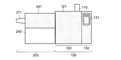
- FIG. 1 is a front view showing the appearance of a GC system including an SCD according to an embodiment of the present invention.
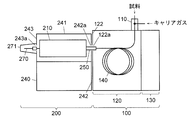
- the front view which shows typically the internal structure of GC and SCD in case SCD is arrange
- Sectional drawing which shows the structure of the heating furnace vicinity of SCD in case SCD is arrange
- the front view which shows typically the internal structure of GC and SCD in case SCD is arrange
- Sectional drawing which shows the structure of the heating furnace vicinity of SCD in case SCD is arrange
- the top view which shows the structure at the time of placing the SCD provided with the removable side panel on the left.
- the top view which shows the structure at the time of placing SCD provided with the removable side panel right.
- FIG. 1 is a front view showing the outer appearance of a gas chromatograph system (GC system) equipped with a chemiluminescent sulfur detector (SCD) according to this embodiment.
- FIG. 2 is a diagram showing a schematic configuration of the SCD according to the present embodiment.
- 3 and 4 are schematic diagrams showing the internal structure of the GC system, FIG. 3 is a front view, and FIG. 4 is a top view.
- FIG. 5 is a cross-sectional view showing the structure near the heating furnace of the SCD.
- FIG. 3, FIG. 4, and FIG. 5 show the state in which the SCD 200 is arranged on the left side of the gas chromatograph (GC) 100, but as will be described later, the SCD 200 according to the present embodiment has the GC 100 You can also place it to the right of.
- GC gas chromatograph
- the GC 100 includes a sample introduction unit 110, a column oven 120 that accommodates and heats a column 140, and a control substrate accommodation unit 130 that accommodates a control substrate (not shown) and the like.
- a front surface of the column oven 120 is a door 121 that can be opened and closed, and an operation panel 131 is provided on the front surface of the control board housing unit 130.
- sample gas a gas containing each separated sample component
- the SCD 200 includes a heating furnace 210, a reaction cell 231, an optical filter 232, a light emission detection unit 233, an ozone generator 234, an ozone scrubber 235, a vacuum pump 236, a flow controller 237, a control/processing unit 238, and And a housing 240 (see FIG. 1) for housing these.
- the SCD 200 is provided at the boundary with the GC 100 and includes an interface 250 for connecting the GC 100 and the SCD 200.
- the heating furnace 210 in the SCD 200 is housed in the upper front side of the casing 240 of the SCD 200, and the reaction cell 231 and other components (not shown in FIGS. 3 and 4) are It is housed in the remaining space inside the housing 240 (for example, below or behind the heating furnace 210).
- the upper surface of the space in which the heating furnace 210 is housed in the housing 240 of the SCD 200 is a removable top plate 241 (see FIG. 1).
- the heating furnace 210 includes an external combustion pipe 211 (corresponding to the “gas flow path” in the present invention), an internal combustion pipe 212, an oxidant supply pipe 213, an inert gas introduction pipe 214, and a heater 215 (in the present invention. (Corresponding to “first heating means”) and a housing 216 that houses them.
- the external combustion pipe 211 is arranged inside the oxidant supply pipe 213 coaxially with the oxidant supply pipe 213, and one end (left end) of the inert gas introduction pipe 214 is inserted into the right end of the external combustion pipe 211. Has been done. Further, one end (right end) of the inner combustion pipe 212 is inserted into the left end of the outer combustion pipe 211.
- the external combustion pipe 211, the internal combustion pipe 212, the oxidant supply pipe 213, and the inert gas introduction pipe 214 are all made of ceramic such as alumina.
- a connector 217 is attached to the right ends of the oxidant supply pipe 213 and the external combustion pipe 211, and the inert gas introduction pipe 214 is inserted through the connector 217.
- the right end openings of the oxidant supply pipe 213 and the external combustion pipe 211 are closed by a connector 217, but a groove is cut on the left end surface of the connector 217, and the oxidant supply pipe 213 is connected via the groove. Gas can flow through the external combustion tube 211.
- the right end of the inert gas introduction pipe 214 projects from the housing 216 of the heating furnace 210, and the pipe 251 (corresponding to the “column passage” in the present invention) provided inside the interface 250 arranged at the boundary between the GC 100 and the SCD 200.
- the interface 250 includes, in addition to the pipe 251, a heater 252 (corresponding to “second heating means” in the present invention) for heating the pipe 251 and a housing 253 that houses the pipe 251 and the heater 252. , An opening 242a provided in the right side wall 242 of the housing 240 of the SCD 200 (corresponding to the "first opening” in the present invention) and an opening 122a provided in the left side wall 122 of the housing of the GC100.
- the right end of the pipe 251 projects from the housing 253 of the interface 250, and the first joint 221 is attached to the right end.
- An inert gas flow path 264 for supplying an inert gas (here, nitrogen) to the inert gas introduction pipe 214 is connected to the first joint 221.
- the first joint 221 is provided with a hole (not shown) for inserting the column 140 of the GC 100.
- the end of the column 140 on the outlet side is inserted into the first joint 221 through this hole, and is inside the heating furnace 210 via the pipe 251 in the interface 250, specifically, inside the inert gas introducing pipe 214.
- the inert gas introduction pipe 214 is inserted to a position slightly to the right of the left end.
- the left ends of the oxidant supply pipe 213, the external combustion pipe 211, and the internal combustion pipe 212 project from the housing 216 of the heating furnace 210, and further, the opening 243a provided in the left side wall 243 of the housing 240 of the SCD 200 (in the present invention, " Corresponding to the "second opening”).
- a second joint 222 is attached to the left end of the oxidant supply pipe 213 outside the housing 240.
- the second joint 222 supplies the oxidant (here, oxygen) to the oxidant supply pipe 213.
- An oxidant flow channel 265 is connected to this.
- the external combustion pipe 211 is inserted through the second joint 222, and the third joint 223 is attached to the left end thereof.
- a reducing agent flow path 266 for supplying a reducing agent (here, hydrogen) to the external combustion pipe 211 is connected to the third joint 223.
- the internal combustion pipe 212 is inserted through the third joint 223, and its left end is connected to the transfer pipe 270 leading to the reaction cell 231.
- the transfer tube 270 is made of a flexible tube, and is folded back outside the housing 240 of the SCD 200 and is opened again from another opening 243b (see FIG. 4) provided in the left side wall 243 of the housing 240 to re-open the housing 240. And is connected to the reaction cell 231 in the housing 240.
- a cover 271 that can be opened and closed is provided on the outer surface of the left side wall 243 of the SCD 200 so as to cover the openings 243a and 243b.
- the inert gas flow channel 264, the oxidant flow channel 265, and the reducing agent flow channel 266 are all connected to the flow controller 237, and the flow controller 237 allows the inert gas supply source 261 and the oxidant supply source 262 to be connected.
- the reducing agent supply source 263 respectively control the flow rates of the gas supplied to the inert gas passage 264, the oxidizing agent passage 265, and the reducing agent passage 266.
- the inert gas supply source 261, the oxidant supply source 262, and the reducing agent supply source 263 may be, for example, gas cylinders filled with nitrogen, oxygen, and hydrogen, respectively.
- the sample gas introduced into the heating furnace 210 from the outlet end of the column 140 of the GC 100 is mixed with oxygen at the right end of the outer combustion tube 211, and moves to the left inside the outer combustion tube 211 at a high temperature. It is oxidatively decomposed.
- the sample component is a sulfur compound
- sulfur dioxide is produced.
- the gas containing the oxidatively decomposed sample component is drawn into the internal combustion pipe 212 together with hydrogen introduced from the vicinity of the left end of the external combustion pipe 211.
- the oxidatively decomposed sample component contains sulfur dioxide, the sulfur dioxide reacts with hydrogen and is reduced to sulfur monoxide.
- the gas that has passed through the internal combustion pipe 212 is introduced into the reaction cell 231 through the transfer pipe 270.
- nitrogen is supplied from the inert gas introduction pipe 214 around the outlet end of the column 140.
- the nitrogen has an effect of preventing detector contamination due to deterioration of the column 140 and an effect of promoting the redox reaction in the heating furnace 210.
- the inside of the heating furnace 210 is heated by the heater 215 at a temperature of 500° C. or higher (desirably 700° C. to 1200° C.) in the highest temperature region. To be heated.
- the gas sent from the transfer pipe 270 to the reaction cell 231 is mixed with ozone in the reaction cell 231.
- chemiluminescence generated by the reaction of sulfur monoxide and ozone is detected by the light emission detection unit 233 including a photomultiplier tube and the like via the optical filter 232.
- the ozone is generated by the ozone generator 234 using oxygen supplied from the oxidant supply source 262 through the oxygen flow path 267, and is supplied to the reaction cell 231.
- the flow controller 237 also controls the flow rate of oxygen supplied to the ozone generator 234 via the oxygen flow path 267.
- An ozone scrubber 235 and a vacuum pump 236 are provided downstream of the reaction cell 231, and the gas in the reaction cell 231 sucked by the vacuum pump 236 has ozone removed by the ozone scrubber 235 and is then exhausted. It is discharged to the outside.
- the detection signal from the luminescence detection unit 233 is sent to the control/processing unit 238, and the control/processing unit 238 determines the concentration of the sulfur compound in the sample gas based on the detection signal.
- the control/processing unit 238 can be embodied by, for example, a microcomputer provided with a CPU, a ROM, a RAM, an input/output circuit for communicating with external peripheral devices, and the like.
- a control program stored in the ROM By executing the arithmetic processing according to the control parameters and the CPU mainly, the processing of the detection signal and the operation control of each part, specifically, the heater 215 of the heating furnace 210, the heater 252 of the interface 250, the light emission.
- the detection unit 233, the ozone generator 234, the vacuum pump 236, the flow controller 237, and the like are controlled.
- the removable top plate 241 is provided on the upper surface of the housing 240 of the SCD 200.
- the heating furnace 210 is taken out of the housing 240, or the housing 240 is heated. 210 can be attached.
- the heating furnace 210 is used with its inlet end (that is, the end into which the column 140 is inserted) facing right, but the housing of the SCD 200 according to this embodiment is used.
- 240 has a configuration capable of holding the heating furnace 210 with the end portion on the inlet side thereof facing to the right or holding the heating furnace 210 to the left.
- the SCD 200 according to the present embodiment is used by arranging it next to the left side of the GC 100 as shown in FIGS. 1 and 3 to 5 (hereinafter referred to as “left placement”), and FIG. As shown in FIG. 8, it can also be used by arranging it on the right side of the GC 100 (hereinafter referred to as “right placement”).
- the SCD 200 according to the present embodiment When the SCD 200 according to the present embodiment is placed on the right side, it is necessary to pull the end of the column 140 on the outlet side into the SCD 200 via the control board housing 130 provided on the right side of the column oven 120 of the GC 100. Therefore, in this case, instead of the interface 250 used for left placement (hereinafter referred to as “left placement interface”), an interface 280 longer than that (hereinafter referred to as “right placement interface”) is used. Must be used. That is, in the SCD 200 according to the present embodiment, two types of model interfaces 250 and 280 for left placement and right placement are prepared in advance, and depending on the usage mode desired by the user (ie, right placement or left placement). Different model interfaces are selectively used.
- the right-hand side interface 280 like the left-hand side interface 250, includes a pipe 281, a heater 282, and a housing 283.
- the outer diameter of the right-hand side interface 280 is equal to that of the left-hand side interface 250, and its length is GC100. It is longer than the width (dimension in the left-right direction) of the control board housing section 130.
- the partition wall 132 between the column oven 120 of the GC 100 and the control board housing part 130 and the right side wall 133 of the control board housing part 130 have openings 132a and 133a, respectively.
- the right-hand side interface 280 is inserted through these openings 132a and 133a.
- the right-hand side interface 280 is inserted through the opening 243a of the left side wall 243 of the housing 240 of the SCD 200, and the oxidant supply pipe 213 protruding from the housing 216 of the heating furnace 210 is inserted into the opening 242a of the right side wall 242 of the SCD 200.
- the ends of the outer combustion pipe 211 and the inner combustion pipe 212 are inserted. Outside the right side wall 242 of the SCD 200, the second joint 222 and the third joint 223 are attached to the ends of the oxidant supply pipe 213 and the outer combustion pipe 211, respectively, and the reaction cell 231 is attached to the end of the inner combustion pipe 212.
- a cover 271 that covers these is provided outside the right side wall 242 of the SCD 200.
- another opening 242b (see FIG. 7) is formed behind the opening 242a of the right side wall 242 of the SCD 200, and when the SCD 200 is placed on the right side, the other opening 242b is formed.
- the transfer pipe 270 is inserted through the 242b.
- the SCD 200 When the SCD 200 is placed on the left side as shown in FIGS. 1 and 3 to 5, it becomes possible to use the SCD 200 together with a device (for example, a pretreatment device) arranged on the right side of the GC 100.
- a device for example, a pretreatment device
- the SCD 200 when the SCD 200 is placed on the right side as shown in FIGS. 6 to 8, the SCD 200 can be used together with a device (for example, MS) arranged on the left side of the GC 100.
- a device for example, MS
- the SCD 200 When the SCD 200 is used together with another GC detector (for example, MS), the outlet end of the column 140 of the GC 100 is branched into two by a branch pipe or the like, one of which is connected to the SCD 200 and the other of Connect to the detector for GC of.
- both the opening 242a provided in the right side wall 242 and the opening 243a provided in the left side wall 243 of the housing 240 of the SCD 200 are connected to the oxidant supply pipe 213, the external combustion pipe 211, and the inside.
- the combustion pipe 212 hereinafter, generically referred to as “oxidant supply pipe or the like”
- the interfaces 250 and 280 can be inserted, in place of this, the left and right side walls may be configured by detachable side panels. Good. The configuration in this case is shown in FIGS.
- a first side panel 244 having an opening 244a through which the interfaces 250 and 280 can be inserted, and an opening 245a through which an oxidant supply pipe and the like can be inserted (and an opening 245b through which the transfer pipe 270 can be inserted).
- the second side panel 245 provided with may be prepared, and these may be appropriately replaced and used.
- the first side panel 244 is attached to the right side of the housing 240 of the SCD 200
- the second side panel 245 is attached to the left side of the housing 240 of the SCD 200. Attach to.
- the first side panel 244 is placed on the right side, as shown in FIG. 10
- the second side panel 245 is placed on the right side of the housing 240 of the SCD 200.
- oxygen is used as the oxidant, but air may be used instead of oxygen.
- nitrogen is used as the inert gas, but other inert gas (for example, helium) can be used.
- the SCD according to the present invention does not have the inert gas supply source 261, the inert gas flow path 264, the inert gas introduction pipe 214, etc. It can also be configured.
Landscapes
- Chemical & Material Sciences (AREA)
- Physics & Mathematics (AREA)
- Analytical Chemistry (AREA)
- General Physics & Mathematics (AREA)
- Pathology (AREA)
- Health & Medical Sciences (AREA)
- Biochemistry (AREA)
- General Health & Medical Sciences (AREA)
- Life Sciences & Earth Sciences (AREA)
- Immunology (AREA)
- Engineering & Computer Science (AREA)
- Chemical Kinetics & Catalysis (AREA)
- Spectroscopy & Molecular Physics (AREA)
- Plasma & Fusion (AREA)
- General Chemical & Material Sciences (AREA)
- Oil, Petroleum & Natural Gas (AREA)
- Investigating Or Analysing Materials By The Use Of Chemical Reactions (AREA)
- Investigating Or Analyzing Non-Biological Materials By The Use Of Chemical Means (AREA)
Abstract
Description
左右に延びる流路であって、その入口側の端部にガスクロマトグラムのカラムの出口側の端部が挿入されるガス流路と、該ガス流路を加熱する第1の加熱手段とを備えた加熱炉と、
前記加熱炉の前記ガス流路を通過したガスをオゾンと反応させる反応セルと、
前記反応セルから出る光を検出する光検出器と、
少なくとも右側壁と左側壁とを有し、前記加熱炉、前記反応セル、及び前記光検出器を収容する筐体と、
前記カラムが挿通されるカラム通路と、該カラム通路を加熱する第2の加熱手段とが設けられたインターフェースと、
を有し、
前記筐体が、前記加熱炉を、前記ガス流路の前記入口側の端部を右に向けた状態及び該入口側の端部を左に向けた状態のいずれでも保持可能であって、且つ前記インターフェースを前記右側壁と前記左側壁のいずれにも取り付け可能であることを特徴としている。
前記筐体が、前記右側壁に前記加熱炉の前記ガス流路と同軸に設けられた第1開口と、前記左側壁に前記ガス流路と同軸に設けられた第2開口とを有しており、
前記インターフェースが、前記第1開口及び前記第2開口のいずれにも挿通可能であるものとすることが望ましい。
前記インターフェースを、互いに長さの異なる2種類のインターフェースから成る群より選ばれたものとすることが望ましい。
このとき、試料成分が硫黄化合物である場合には、二酸化硫黄が生成される。酸化分解された試料成分を含むガスは、外部燃焼管211の左端付近から導入される水素と共に内部燃焼管212に引き込まれる。前記酸化分解された試料成分に二酸化硫黄が含まれる場合は、ここで二酸化硫黄が水素と反応して一酸化硫黄に還元される。内部燃焼管212を通過したガスは、移送管270を通じて反応セル231に導入される。
110…試料導入部
120…カラムオーブン
130…制御基板収容部
140…カラム
200…SCD
210…加熱炉
211…外部燃焼管
212…内部燃焼管
213…酸化剤供給管
214…不活性ガス導入管
215…ヒータ
216…ハウジング
231…反応セル
232…光学フィルタ
233…発光検出部
234…オゾン発生器
235…オゾンスクラバ
236…真空ポンプ
237…フローコントローラ
238…制御/処理部
240…筐体
242…右側壁
242a…開口
243…左側壁
243a…開口
250、280…インターフェース
270…右置き用インターフェース
251、281…配管
252、282…ヒータ
253、283…ハウジング
244…第1のサイドパネル
245…第2のサイドパネル
Claims (3)
- 左右に延びる流路であって、その入口側の端部にガスクロマトグラムのカラムの出口側の端部が挿入されるガス流路と、該ガス流路を加熱する第1の加熱手段とを備えた加熱炉と、
前記加熱炉の前記ガス流路を通過したガスをオゾンと反応させる反応セルと、
前記反応セルから出る光を検出する光検出器と、
少なくとも右側壁と左側壁とを有し、前記加熱炉、前記反応セル、及び前記光検出器を収容する筐体と、
前記カラムが挿通されるカラム通路と、該カラム通路を加熱する第2の加熱手段とが設けられたインターフェースと、
を有し、
前記筐体が、前記加熱炉を、前記ガス流路の前記入口側の端部を右に向けた状態及び該入口側の端部を左に向けた状態のいずれでも保持可能であって、且つ前記インターフェースを前記右側壁と前記左側壁のいずれにも取り付け可能であることを特徴とする化学発光硫黄検出器。 - 前記筐体が、前記右側壁に前記加熱炉の前記ガス流路と同軸に設けられた第1開口と、前記左側壁に前記ガス流路と同軸に設けられた第2開口とを有しており、
前記インターフェースが、前記第1開口及び前記第2開口のいずれにも挿通可能であることを特徴とする請求項1に記載の化学発光硫黄検出器。 - 前記インターフェースは、互いに長さの異なる2種類のインターフェースから成る群より選ばれたものであることを特徴とする請求項1に記載の化学発光硫黄検出器。
Priority Applications (9)
| Application Number | Priority Date | Filing Date | Title |
|---|---|---|---|
| CN201880099712.XA CN113167732B (zh) | 2018-12-12 | 2018-12-12 | 硫化学发光检测器 |
| US17/293,734 US12379321B2 (en) | 2018-12-12 | 2018-12-12 | Sulfur chemiluminescence detector |
| PCT/JP2018/045623 WO2020121426A1 (ja) | 2018-12-12 | 2018-12-12 | 化学発光硫黄検出器 |
| JP2020559595A JP7036228B2 (ja) | 2018-12-12 | 2018-12-12 | 化学発光硫黄検出器 |
| CN201980081588.9A CN113167734B (zh) | 2018-12-12 | 2019-01-29 | 成分分析系统和成分检测装置 |
| US17/298,301 US12345651B2 (en) | 2018-12-12 | 2019-01-29 | Gas chromatographic component analysis system and component detector including an oxidation-reduction furnace, reaction cell and photodetector |
| PCT/JP2019/002999 WO2020121539A1 (ja) | 2018-12-12 | 2019-01-29 | 成分分析システムおよび成分検出装置 |
| JP2020559681A JP7207422B2 (ja) | 2018-12-12 | 2019-01-29 | 成分分析システムおよび成分検出装置 |
| JP2022206085A JP7400935B2 (ja) | 2018-12-12 | 2022-12-22 | 成分分析システムおよび成分検出装置 |
Applications Claiming Priority (1)
| Application Number | Priority Date | Filing Date | Title |
|---|---|---|---|
| PCT/JP2018/045623 WO2020121426A1 (ja) | 2018-12-12 | 2018-12-12 | 化学発光硫黄検出器 |
Publications (1)
| Publication Number | Publication Date |
|---|---|
| WO2020121426A1 true WO2020121426A1 (ja) | 2020-06-18 |
Family
ID=71075987
Family Applications (2)
| Application Number | Title | Priority Date | Filing Date |
|---|---|---|---|
| PCT/JP2018/045623 Ceased WO2020121426A1 (ja) | 2018-12-12 | 2018-12-12 | 化学発光硫黄検出器 |
| PCT/JP2019/002999 Ceased WO2020121539A1 (ja) | 2018-12-12 | 2019-01-29 | 成分分析システムおよび成分検出装置 |
Family Applications After (1)
| Application Number | Title | Priority Date | Filing Date |
|---|---|---|---|
| PCT/JP2019/002999 Ceased WO2020121539A1 (ja) | 2018-12-12 | 2019-01-29 | 成分分析システムおよび成分検出装置 |
Country Status (4)
| Country | Link |
|---|---|
| US (2) | US12379321B2 (ja) |
| JP (3) | JP7036228B2 (ja) |
| CN (2) | CN113167732B (ja) |
| WO (2) | WO2020121426A1 (ja) |
Cited By (1)
| Publication number | Priority date | Publication date | Assignee | Title |
|---|---|---|---|---|
| US12345651B2 (en) | 2018-12-12 | 2025-07-01 | Shimadzu Corporation | Gas chromatographic component analysis system and component detector including an oxidation-reduction furnace, reaction cell and photodetector |
Families Citing this family (1)
| Publication number | Priority date | Publication date | Assignee | Title |
|---|---|---|---|---|
| CN113167733B (zh) * | 2018-12-20 | 2024-02-06 | 株式会社岛津制作所 | 硫化学发光检测器 |
Citations (4)
| Publication number | Priority date | Publication date | Assignee | Title |
|---|---|---|---|---|
| JP2015059876A (ja) * | 2013-09-20 | 2015-03-30 | 株式会社島津製作所 | 酸化装置、化学発光検出器及びガスクロマトグラフ |
| WO2015083794A1 (ja) * | 2013-12-05 | 2015-06-11 | 株式会社堀場エステック | ガスクロマトグラフ |
| WO2018139920A1 (en) * | 2017-01-26 | 2018-08-02 | Ac Analytical Controls B.V. | A furnace suited for chemiluminescent sulphur detection |
| WO2018168599A1 (ja) * | 2017-03-15 | 2018-09-20 | 株式会社島津製作所 | 化学発光検出器用反応装置及びこれを備えた化学発光検出器、並びに、化学発光検出方法 |
Family Cites Families (116)
| Publication number | Priority date | Publication date | Assignee | Title |
|---|---|---|---|---|
| US2000119A (en) * | 1930-09-11 | 1935-05-07 | Brown Instr Co | Apparatus for gas analyses |
| US1984933A (en) * | 1931-10-17 | 1934-12-18 | Forest City Foundries Company | Furnace structure |
| US2060599A (en) * | 1933-03-23 | 1936-11-10 | Ray F Van Seggern | Heating unit for combustion chambers |
| US2147606A (en) | 1934-04-05 | 1939-02-14 | Texas Co | Method of and apparatus for gas analysis |
| US3399038A (en) * | 1962-10-12 | 1968-08-27 | Aquitaine Petrole | Apparatus for determining sulfur content of gaseous hydrocarbons |
| GB1066317A (en) | 1963-10-14 | 1967-04-26 | Perkin Elmer Ltd | Improvements relating to apparatus for use in gas chromatography |
| US3698869A (en) | 1965-08-20 | 1972-10-17 | Perkin Elmer Corp | Analysis of gaseous mixtures |
| US3527567A (en) * | 1967-09-15 | 1970-09-08 | Shell Oil Co | Analytical distillation by gas chromatography |
| US3898041A (en) * | 1971-03-01 | 1975-08-05 | Envirotech Corp | Fluid sampler apparatus and method |
| US4044593A (en) | 1971-03-31 | 1977-08-30 | Shimadzu Seisakusho Ltd. | Chromatograph |
| NL7105976A (ja) * | 1971-04-30 | 1972-11-01 | ||
| US3749929A (en) | 1971-10-07 | 1973-07-31 | Monsanto Res Corp | Chemiluminescent method and apparatus |
| US3703355A (en) * | 1971-12-10 | 1972-11-21 | Envirotech Corp | Pyrolysis and analysis system |
| US3848128A (en) | 1972-06-30 | 1974-11-12 | Mcmillan Electronics Corp | Control chamber apparatus for pollutant detectors |
| US3861874A (en) * | 1973-03-07 | 1975-01-21 | Shell Oil Co | Total recovery thermal analysis system |
| US3877875A (en) * | 1973-07-19 | 1975-04-15 | Beckman Instruments Inc | Nitrogen constituent analysis |
| US3904371A (en) | 1974-03-04 | 1975-09-09 | Beckman Instruments Inc | Chemiluminescent ammonia detection |
| US4193963A (en) | 1974-09-20 | 1980-03-18 | Petroleo Brasileiro S.A.-Petrobras | Apparatus for the determination of chemical compounds by chemiluminescence with ozone |
| US4843016A (en) * | 1974-10-07 | 1989-06-27 | Thermedics Inc. | Detection system and method |
| US4778764A (en) * | 1974-10-07 | 1988-10-18 | Thermedics Inc. | Detection system and method |
| US4018562A (en) * | 1975-10-24 | 1977-04-19 | Antek Instruments, Inc. | Chemiluminescent nitrogen detection apparatus and method |
| US4087249A (en) * | 1975-12-26 | 1978-05-02 | Toyoda Gosei Co., Ltd. | Pyrolysis apparatus for analysis |
| US4054414A (en) * | 1976-11-30 | 1977-10-18 | Villanova University | Gas chromatographic method for the multi-elemental microanalysis of organic materials |
| US4070155A (en) * | 1977-01-19 | 1978-01-24 | Thermo Electron Corporation | Apparatus for chromatographically analyzing a liquid sample |
| US4066411A (en) * | 1977-01-19 | 1978-01-03 | Thermo Electron Corporation | N-nitroso compound analyzer with sample atomization |
| US4066409A (en) | 1977-01-19 | 1978-01-03 | Thermo Electron Corporation | Method and apparatus for chromatographically analyzing a liquid sample |
| US4118193A (en) | 1977-07-29 | 1978-10-03 | Beckman Instruments, Inc. | Catalytic reactor systems method and apparatus |
| US4227887A (en) * | 1978-08-28 | 1980-10-14 | Envirotech Corporation | Determination of total organic halides in water |
| US4244917A (en) * | 1979-05-09 | 1981-01-13 | Conoco, Inc. | Sample pyrolysis oven |
| US4301114A (en) * | 1980-06-30 | 1981-11-17 | Thermo Electron Corporation | Molecular sieve trap for nitrogen compound detection |
| JPS57110961A (en) * | 1980-12-26 | 1982-07-10 | Nippon Kokan Kk <Nkk> | Analyzing device for sulphur content in fuel |
| US4409336A (en) * | 1981-02-17 | 1983-10-11 | Standard Oil Company (Indiana) | Method of analysis for determining very low sulfur levels in volatilizable samples |
| US4333735A (en) * | 1981-03-16 | 1982-06-08 | Exxon Research & Engineering Co. | Process and apparatus for measuring gaseous fixed nitrogen species |
| US4569918A (en) * | 1982-02-02 | 1986-02-11 | Xertex Corporation | Sulfur dioxide analysis system |
| US4599218A (en) | 1982-03-01 | 1986-07-08 | Chevron Research Company | Capture box for predicting hydrocarbon potential of an earth formation underlying a body of water |
| JPS6010170A (ja) | 1983-06-30 | 1985-01-19 | Hitachi Ltd | アンモニア性過酸化水素液中のアンモニアと過酸化水素の濃度を測定する方法およびその装置 |
| JPH0650305B2 (ja) * | 1984-02-10 | 1994-06-29 | 株式会社島津製作所 | 元素分析方法および装置 |
| FR2566125B1 (fr) * | 1984-06-18 | 1986-08-29 | Inst Francais Du Petrole | Dispositif utilisable notamment pour la pyrolyse d'echantillons solides ou liquides preleves en faible quantite |
| US4587835A (en) | 1985-01-09 | 1986-05-13 | International Business Machines Corp. | Light pipe and heater apparatus |
| US4985625A (en) * | 1986-03-06 | 1991-01-15 | Finnigan Corporation | Transfer line for mass spectrometer apparatus |
| US4916077A (en) * | 1987-02-27 | 1990-04-10 | Shell Oil Company | Method and apparatus for oxidative decomposition and analysis of a sample |
| US4950456A (en) * | 1987-02-27 | 1990-08-21 | Shell Oil Company | Apparatus for analysis of a sample for sulphur |
| US4851683A (en) | 1987-03-09 | 1989-07-25 | Brigham Young University | Element specific radio frequency discharge helium plasma detector for chromatography |
| GB8720586D0 (en) | 1987-09-02 | 1987-10-07 | Vg Instr Group | Apparatus & method |
| US5012052A (en) * | 1988-03-22 | 1991-04-30 | Indiana University Foundation | Isotope-ratio-monitoring gas chromatography-mass spectrometry apparatus and method |
| US4985925A (en) | 1988-06-24 | 1991-01-15 | Sensor Electronics, Inc. | Active noise reduction system |
| US5501981A (en) * | 1988-11-25 | 1996-03-26 | Sievers Instruments, Inc. | Method and apparatus for chemiluminescent detection of sulfur |
| JPH02201156A (ja) * | 1989-01-30 | 1990-08-09 | Dow Chem Nippon Kk | ガスクロマトグラフィー用熱分解装置 |
| US4970905A (en) * | 1989-05-25 | 1990-11-20 | University Of Utah | Apparatus and method for sampling |
| US5298225A (en) * | 1991-12-23 | 1994-03-29 | Microsensor Technology, Inc. | Detachable column cartridge gas chromatograph |
| US6130095A (en) * | 1992-01-23 | 2000-10-10 | Sievers Instruments, Inc. | Method for the measurement of sulfur compounds |
| JP3104383B2 (ja) * | 1992-02-27 | 2000-10-30 | 株式会社島津製作所 | 化学発光式濃度測定装置 |
| US5242471A (en) | 1992-05-22 | 1993-09-07 | The Dow Chemical Company | Coupling capillary gas chromatography to traditional liquid chromatography detectors |
| US5352611A (en) | 1992-06-01 | 1994-10-04 | The Coca-Cola Company | Method and system for sampling and determining the presence of compounds in containers |
| US5470754A (en) | 1992-06-01 | 1995-11-28 | The Coca-Cola Company | Method and system for sampling and determining the presence of compounds |
| US5614417A (en) | 1993-10-07 | 1997-03-25 | Kubala; Sidney W. | Sulfur chemiluminescence detection method |
| GB9418638D0 (en) * | 1994-09-15 | 1994-11-02 | Fisons Plc | Isotopic composition analyser |
| CA2159657A1 (en) * | 1995-11-08 | 1997-05-09 | David Kirk | Method and apparatus for the measurement of sulfur compounds in process or transmission streams |
| US5916523A (en) * | 1996-12-04 | 1999-06-29 | Antek Instruments, Inc. | Methods for near simultaneous chemiluminescent sulfur and nitrogen detection |
| US5783741A (en) * | 1997-01-31 | 1998-07-21 | Atlantic Richfield Company | Capillary furnace for improved peak resolution in gas isotope chromatography |
| JP2002517979A (ja) | 1997-02-28 | 2002-06-18 | エクストラクション・システムズ・インコーポレーテッド | 気体におけるアミンおよび他の塩基性分子の汚染を検出するためのシステム |
| US6096267A (en) | 1997-02-28 | 2000-08-01 | Extraction Systems, Inc. | System for detecting base contaminants in air |
| US6057162A (en) * | 1997-03-07 | 2000-05-02 | Thermedics Detection, Inc. | Disease diagnosis by vapor sample analysis |
| US5980832A (en) * | 1997-09-23 | 1999-11-09 | The Regents Of The University Of California | Ultratrace detector for hand-held gas chromatography |
| DE19817016C2 (de) * | 1998-04-17 | 2000-02-03 | Gerstel Gmbh & Co Kg | Probenaufgabeeinrichtung für einen Gaschromatopgraphen |
| US6207460B1 (en) | 1999-01-14 | 2001-03-27 | Extraction Systems, Inc. | Detection of base contaminants in gas samples |
| US6458328B1 (en) * | 1999-03-05 | 2002-10-01 | Antek Instruments, L.P. | Staged oxidation chamber for enhanced nitrogen and sulfur detection |
| NL1012127C2 (nl) | 1999-05-21 | 2000-11-23 | Sgt Exploitatie Bv | Samenstel voor het desorberen van bemonsteringsbuisjes, alsmede een adaptor en bemonsteringsbuisjes kennelijk bestemd voor een dergelijk samenstel, alsmede een kit van onderdelen ter vorming van een dergelijk samenstel. |
| AU6092200A (en) | 1999-07-13 | 2001-01-30 | The Texas A & M University System | Pneumatic nebulizing interface, method for making and using same and instruments including same |
| JP2004520566A (ja) | 1999-12-20 | 2004-07-08 | アーヨット イーデーツェー ゲレーテエントヴィックルングスゲゼルシャフト エムベーハー | 試料中の全硫黄含有量の測定システム |
| AU782271B2 (en) | 2000-01-25 | 2005-07-14 | State Of Oregon Acting By And Through The State Board Of Higher Education On Behalf Of Portland State University, The | Method and apparatus for concentrating samples for analysis |
| US6830730B2 (en) * | 2001-09-11 | 2004-12-14 | Spectrolanalytical Instruments | Method and apparatus for the on-stream analysis of total sulfur and/or nitrogen in petroleum products |
| US7029920B2 (en) | 2001-10-31 | 2006-04-18 | General Electric Company | Method and system for monitoring combustion source emissions |
| US6530260B1 (en) | 2002-02-04 | 2003-03-11 | Rvm Scientific, Inc. | Gas chromatography analysis system |
| US20040151630A1 (en) | 2002-08-26 | 2004-08-05 | Hernandez Herbert A. | Total nitrogen and sulphur analysis using a catalytic combustion gas converter system |
| JP3977218B2 (ja) * | 2002-09-30 | 2007-09-19 | 株式会社ダイアインスツルメンツ | 試料加熱装置 |
| JP4109578B2 (ja) * | 2003-06-13 | 2008-07-02 | 株式会社堀場製作所 | 化学発光式ガス分析方法および装置 |
| US7244395B2 (en) | 2003-09-29 | 2007-07-17 | Petroleum Analyzer Company, Lp | Apparatus for trace sulfur detection using UV fluorescence |
| US20050129578A1 (en) * | 2003-10-21 | 2005-06-16 | Petroleum Analyzer Company, Lp | Fast system for detecting detectible combustion products and method for making and using same |
| US7407381B2 (en) * | 2003-10-21 | 2008-08-05 | Pac, Lp | Combustion apparatus and methods for making and using same |
| JP4807355B2 (ja) | 2005-03-31 | 2011-11-02 | 東洋製罐株式会社 | 気液二相流クロマトグラフ分析装置及び該装置を用いる分析方法 |
| US7454952B2 (en) | 2005-05-02 | 2008-11-25 | Thermo Fisher Scientific Inc. | Method and apparatus for monitoring mercury in a gas sample |
| US7354553B2 (en) | 2005-05-02 | 2008-04-08 | Dirk Appel | Method and apparatus for detecting the presence of elemental mercury in a gas sample |
| US7509837B2 (en) | 2005-10-18 | 2009-03-31 | Separation Systems, Inc. | Method and system for chemical and physical characterization of complex samples |
| IL176724A (en) | 2006-07-06 | 2010-06-16 | Aviv Amirav | Method and apparatus for pulsed flow modulation gas chromatography mass spectrometry with supersonic molecular beams |
| JP4967141B2 (ja) * | 2006-09-12 | 2012-07-04 | 独立行政法人海洋研究開発機構 | 元素分析用前処理装置 |
| GB2445184B (en) * | 2006-12-29 | 2009-05-06 | Thermo Fisher Scientific Inc | Combustion analyser sample introduction apparatus and method |
| GB2447707B (en) * | 2007-03-23 | 2009-11-11 | Thermo Fisher Scientific Inc | Combustion tube and method for combusting a sample for combustion analysis |
| DE102007031680A1 (de) * | 2007-07-06 | 2009-01-08 | Thermo Fisher Scientific (Bremen) Gmbh | Einrichtung zur Bereitstellung von Gasen, insbesondere für die Isotopenverhältnisanalyse |
| JP4872902B2 (ja) * | 2007-12-17 | 2012-02-08 | 株式会社島津製作所 | マルチディメンジョナルガスクロマトグラフシステム |
| CN201173899Y (zh) * | 2008-03-14 | 2008-12-31 | 朱明俊 | 脉冲式紫外荧光法测硫专用石英管 |
| WO2009135115A1 (en) | 2008-05-01 | 2009-11-05 | The Govt. Of The U.S.A. As Represented By The Secretary Of The Navy Naval Research Laboratory | Microfabricated gas chromatograph |
| WO2010048548A2 (en) * | 2008-10-23 | 2010-04-29 | Woods Hole Oceanographic Institution | Gas chromatograph-combustion system and method for mass spectrometry |
| US20100118301A1 (en) | 2008-11-13 | 2010-05-13 | Petroleum Analyzer Company, L.P. | System for analyzing a sample or a sample component and method for making and using same |
| JP5396245B2 (ja) * | 2009-11-13 | 2014-01-22 | 独立行政法人海洋研究開発機構 | 元素分析用前処理装置及び元素分析装置 |
| US8511141B2 (en) | 2009-12-23 | 2013-08-20 | Brand-Gaus, Llc | Stack gas measurement device and method therefor |
| US9745191B2 (en) * | 2011-04-11 | 2017-08-29 | Saudi Arabian Oil Company | Auto thermal reforming (ATR) catalytic structures |
| JP2013057641A (ja) * | 2011-09-09 | 2013-03-28 | Sumitomo Rubber Ind Ltd | 高分子試料分析装置 |
| US8378293B1 (en) | 2011-09-09 | 2013-02-19 | Agilent Technologies, Inc. | In-situ conditioning in mass spectrometer systems |
| US20140017129A1 (en) * | 2012-07-13 | 2014-01-16 | Taiyo Nippon Sanso Corporation | Oxidation method and oxidation apparatus of sulfur compounds in sample gas and analysis apparatus for sulfur compounds |
| US20140219868A1 (en) * | 2013-02-04 | 2014-08-07 | Horiba Stec, Co., Ltd. | Reaction apparatus, control device, and control program |
| CN103175825A (zh) * | 2013-02-05 | 2013-06-26 | 中联煤层气国家工程研究中心有限责任公司 | 一种检测煤层气中硫化物含量的方法和装置 |
| CN103336070B (zh) * | 2013-06-17 | 2015-09-16 | 广东电网公司电力科学研究院 | 一种定量检测六氟化硫电气设备中含硫故障气体组分的检测装置及方法 |
| EP3059586A4 (en) * | 2013-09-25 | 2017-05-31 | Shimadzu Corporation | Gas chromatograph-mass spectrometer |
| JP2015075355A (ja) * | 2013-10-07 | 2015-04-20 | 株式会社島津製作所 | クロマトグラフ質量分析装置 |
| EP3377217A1 (en) * | 2015-11-18 | 2018-09-26 | ExxonMobil Research and Engineering Company | Heat-resistant hydrocarbon reforming catalyst based on rhodium on a lanthanum-stabilised theta-alumina |
| CN108291892B (zh) * | 2015-12-04 | 2021-06-04 | 株式会社岛津制作所 | 液体试样分析系统 |
| NL2017426B1 (en) * | 2016-09-06 | 2018-03-13 | Ac Analytical Controls B V | Method for chemiluminescent sulphur detection and a furnace |
| JP3210660U (ja) * | 2017-03-15 | 2017-06-01 | 株式会社島津製作所 | 化学発光検出器用反応装置及びこれを備えた化学発光検出器 |
| CN113056671B (zh) | 2018-11-29 | 2024-07-30 | 株式会社岛津制作所 | 气相色谱系统 |
| CN113167732B (zh) | 2018-12-12 | 2025-01-28 | 株式会社岛津制作所 | 硫化学发光检测器 |
| CN113167733B (zh) * | 2018-12-20 | 2024-02-06 | 株式会社岛津制作所 | 硫化学发光检测器 |
| JP7099344B2 (ja) * | 2019-02-01 | 2022-07-12 | 株式会社島津製作所 | 化学発光硫黄検出器 |
| KR102825281B1 (ko) * | 2019-10-07 | 2025-06-24 | 후아웨이 테크놀러지 컴퍼니 리미티드 | 다중 레이어 비디오 비트스트림에서의 중복 시그널링의 방지 |
| US12093812B2 (en) * | 2020-10-02 | 2024-09-17 | Sandisk Technologies Llc | Ultralow power inference engine with external magnetic field programming assistance |
| JP2025110961A (ja) * | 2024-01-17 | 2025-07-30 | ブラザー工業株式会社 | サポートプログラム |
-
2018
- 2018-12-12 CN CN201880099712.XA patent/CN113167732B/zh active Active
- 2018-12-12 WO PCT/JP2018/045623 patent/WO2020121426A1/ja not_active Ceased
- 2018-12-12 US US17/293,734 patent/US12379321B2/en active Active
- 2018-12-12 JP JP2020559595A patent/JP7036228B2/ja active Active
-
2019
- 2019-01-29 JP JP2020559681A patent/JP7207422B2/ja active Active
- 2019-01-29 CN CN201980081588.9A patent/CN113167734B/zh active Active
- 2019-01-29 WO PCT/JP2019/002999 patent/WO2020121539A1/ja not_active Ceased
- 2019-01-29 US US17/298,301 patent/US12345651B2/en active Active
-
2022
- 2022-12-22 JP JP2022206085A patent/JP7400935B2/ja active Active
Patent Citations (4)
| Publication number | Priority date | Publication date | Assignee | Title |
|---|---|---|---|---|
| JP2015059876A (ja) * | 2013-09-20 | 2015-03-30 | 株式会社島津製作所 | 酸化装置、化学発光検出器及びガスクロマトグラフ |
| WO2015083794A1 (ja) * | 2013-12-05 | 2015-06-11 | 株式会社堀場エステック | ガスクロマトグラフ |
| WO2018139920A1 (en) * | 2017-01-26 | 2018-08-02 | Ac Analytical Controls B.V. | A furnace suited for chemiluminescent sulphur detection |
| WO2018168599A1 (ja) * | 2017-03-15 | 2018-09-20 | 株式会社島津製作所 | 化学発光検出器用反応装置及びこれを備えた化学発光検出器、並びに、化学発光検出方法 |
Non-Patent Citations (1)
| Title |
|---|
| ANONYMOUS: "Sulfur Chemiluminescence Detector (SCD): Basic Operation and Maintenance Manual", 31 December 2007 (2007-12-31), XP055720413, Retrieved from the Internet <URL:https://www.chem-agilent.com/cimg/SCD.pdf> [retrieved on 20190225] * |
Cited By (2)
| Publication number | Priority date | Publication date | Assignee | Title |
|---|---|---|---|---|
| US12345651B2 (en) | 2018-12-12 | 2025-07-01 | Shimadzu Corporation | Gas chromatographic component analysis system and component detector including an oxidation-reduction furnace, reaction cell and photodetector |
| US12379321B2 (en) | 2018-12-12 | 2025-08-05 | Shimadzu Corporation | Sulfur chemiluminescence detector |
Also Published As
| Publication number | Publication date |
|---|---|
| US12345651B2 (en) | 2025-07-01 |
| JP2023052048A (ja) | 2023-04-11 |
| US20220026406A1 (en) | 2022-01-27 |
| JPWO2020121539A1 (ja) | 2021-10-07 |
| CN113167734B (zh) | 2025-05-13 |
| JPWO2020121426A1 (ja) | 2021-10-14 |
| US20220011237A1 (en) | 2022-01-13 |
| JP7207422B2 (ja) | 2023-01-18 |
| WO2020121539A1 (ja) | 2020-06-18 |
| CN113167732B (zh) | 2025-01-28 |
| CN113167732A (zh) | 2021-07-23 |
| US12379321B2 (en) | 2025-08-05 |
| JP7400935B2 (ja) | 2023-12-19 |
| CN113167734A (zh) | 2021-07-23 |
| JP7036228B2 (ja) | 2022-03-15 |
Similar Documents
| Publication | Publication Date | Title |
|---|---|---|
| JP2020125922A (ja) | 化学発光硫黄検出器 | |
| JP7036228B2 (ja) | 化学発光硫黄検出器 | |
| JPH11133000A5 (ja) | ||
| Ross et al. | Reverse flow continuous corona discharge ionisation applied to ion mobility spectrometry | |
| JP7070703B2 (ja) | ガスクロマトグラフシステム | |
| WO2018168599A1 (ja) | 化学発光検出器用反応装置及びこれを備えた化学発光検出器、並びに、化学発光検出方法 | |
| JP7052884B2 (ja) | 化学発光硫黄検出器 | |
| JP2014185953A (ja) | ガスクロマトグラフ装置 | |
| KR20130123293A (ko) | 기체 화합물의 자외선 분광 분석 장치 | |
| JP5093377B2 (ja) | 電子捕獲検出器 | |
| JP2008190942A (ja) | ガスクロマトグラフ装置 | |
| JP7156406B2 (ja) | 化学発光硫黄検出器 | |
| CN103270370A (zh) | 原子吸收仪 | |
| JP3206240U (ja) | 分析装置 | |
| US20250044262A1 (en) | Liquid chromatograph detector | |
| JP2007178288A (ja) | Voc放散試験装置 | |
| JP2023088687A (ja) | ガス検知器 | |
| JP2004245714A (ja) | ガス計測装置 | |
| JP2023102021A (ja) | Icp分析装置 | |
| JP2006162564A (ja) | 光イオン化検出器 |
Legal Events
| Date | Code | Title | Description |
|---|---|---|---|
| 121 | Ep: the epo has been informed by wipo that ep was designated in this application |
Ref document number: 18943105 Country of ref document: EP Kind code of ref document: A1 |
|
| ENP | Entry into the national phase |
Ref document number: 2020559595 Country of ref document: JP Kind code of ref document: A |
|
| NENP | Non-entry into the national phase |
Ref country code: DE |
|
| 122 | Ep: pct application non-entry in european phase |
Ref document number: 18943105 Country of ref document: EP Kind code of ref document: A1 |
|
| WWG | Wipo information: grant in national office |
Ref document number: 201880099712.X Country of ref document: CN |
|
| WWG | Wipo information: grant in national office |
Ref document number: 17293734 Country of ref document: US |