WO2020116643A1 - 加炭材およびそれを用いた加炭方法 - Google Patents
加炭材およびそれを用いた加炭方法 Download PDFInfo
- Publication number
- WO2020116643A1 WO2020116643A1 PCT/JP2019/047930 JP2019047930W WO2020116643A1 WO 2020116643 A1 WO2020116643 A1 WO 2020116643A1 JP 2019047930 W JP2019047930 W JP 2019047930W WO 2020116643 A1 WO2020116643 A1 WO 2020116643A1
- Authority
- WO
- WIPO (PCT)
- Prior art keywords
- carburizing
- mass
- ash
- molten iron
- carbon material
- Prior art date
- Legal status (The legal status is an assumption and is not a legal conclusion. Google has not performed a legal analysis and makes no representation as to the accuracy of the status listed.)
- Ceased
Links
Images


Classifications
-
- C—CHEMISTRY; METALLURGY
- C21—METALLURGY OF IRON
- C21C—PROCESSING OF PIG-IRON, e.g. REFINING, MANUFACTURE OF WROUGHT-IRON OR STEEL; TREATMENT IN MOLTEN STATE OF FERROUS ALLOYS
- C21C7/00—Treating molten ferrous alloys, e.g. steel, not covered by groups C21C1/00 - C21C5/00
- C21C7/0025—Adding carbon material
-
- C—CHEMISTRY; METALLURGY
- C23—COATING METALLIC MATERIAL; COATING MATERIAL WITH METALLIC MATERIAL; CHEMICAL SURFACE TREATMENT; DIFFUSION TREATMENT OF METALLIC MATERIAL; COATING BY VACUUM EVAPORATION, BY SPUTTERING, BY ION IMPLANTATION OR BY CHEMICAL VAPOUR DEPOSITION, IN GENERAL; INHIBITING CORROSION OF METALLIC MATERIAL OR INCRUSTATION IN GENERAL
- C23C—COATING METALLIC MATERIAL; COATING MATERIAL WITH METALLIC MATERIAL; SURFACE TREATMENT OF METALLIC MATERIAL BY DIFFUSION INTO THE SURFACE, BY CHEMICAL CONVERSION OR SUBSTITUTION; COATING BY VACUUM EVAPORATION, BY SPUTTERING, BY ION IMPLANTATION OR BY CHEMICAL VAPOUR DEPOSITION, IN GENERAL
- C23C8/00—Solid state diffusion of only non-metal elements into metallic material surfaces; Chemical surface treatment of metallic material by reaction of the surface with a reactive gas, leaving reaction products of surface material in the coating, e.g. conversion coatings, passivation of metals
- C23C8/02—Pretreatment of the material to be coated
-
- C—CHEMISTRY; METALLURGY
- C21—METALLURGY OF IRON
- C21C—PROCESSING OF PIG-IRON, e.g. REFINING, MANUFACTURE OF WROUGHT-IRON OR STEEL; TREATMENT IN MOLTEN STATE OF FERROUS ALLOYS
- C21C5/00—Manufacture of carbon-steel, e.g. plain mild steel, medium carbon steel or cast steel or stainless steel
- C21C5/52—Manufacture of steel in electric furnaces
-
- C—CHEMISTRY; METALLURGY
- C21—METALLURGY OF IRON
- C21C—PROCESSING OF PIG-IRON, e.g. REFINING, MANUFACTURE OF WROUGHT-IRON OR STEEL; TREATMENT IN MOLTEN STATE OF FERROUS ALLOYS
- C21C5/00—Manufacture of carbon-steel, e.g. plain mild steel, medium carbon steel or cast steel or stainless steel
- C21C5/52—Manufacture of steel in electric furnaces
- C21C5/527—Charging of the electric furnace
-
- C—CHEMISTRY; METALLURGY
- C21—METALLURGY OF IRON
- C21C—PROCESSING OF PIG-IRON, e.g. REFINING, MANUFACTURE OF WROUGHT-IRON OR STEEL; TREATMENT IN MOLTEN STATE OF FERROUS ALLOYS
- C21C7/00—Treating molten ferrous alloys, e.g. steel, not covered by groups C21C1/00 - C21C5/00
-
- C—CHEMISTRY; METALLURGY
- C21—METALLURGY OF IRON
- C21C—PROCESSING OF PIG-IRON, e.g. REFINING, MANUFACTURE OF WROUGHT-IRON OR STEEL; TREATMENT IN MOLTEN STATE OF FERROUS ALLOYS
- C21C7/00—Treating molten ferrous alloys, e.g. steel, not covered by groups C21C1/00 - C21C5/00
- C21C7/0037—Treating molten ferrous alloys, e.g. steel, not covered by groups C21C1/00 - C21C5/00 by injecting powdered material
-
- C—CHEMISTRY; METALLURGY
- C23—COATING METALLIC MATERIAL; COATING MATERIAL WITH METALLIC MATERIAL; CHEMICAL SURFACE TREATMENT; DIFFUSION TREATMENT OF METALLIC MATERIAL; COATING BY VACUUM EVAPORATION, BY SPUTTERING, BY ION IMPLANTATION OR BY CHEMICAL VAPOUR DEPOSITION, IN GENERAL; INHIBITING CORROSION OF METALLIC MATERIAL OR INCRUSTATION IN GENERAL
- C23C—COATING METALLIC MATERIAL; COATING MATERIAL WITH METALLIC MATERIAL; SURFACE TREATMENT OF METALLIC MATERIAL BY DIFFUSION INTO THE SURFACE, BY CHEMICAL CONVERSION OR SUBSTITUTION; COATING BY VACUUM EVAPORATION, BY SPUTTERING, BY ION IMPLANTATION OR BY CHEMICAL VAPOUR DEPOSITION, IN GENERAL
- C23C8/00—Solid state diffusion of only non-metal elements into metallic material surfaces; Chemical surface treatment of metallic material by reaction of the surface with a reactive gas, leaving reaction products of surface material in the coating, e.g. conversion coatings, passivation of metals
- C23C8/06—Solid state diffusion of only non-metal elements into metallic material surfaces; Chemical surface treatment of metallic material by reaction of the surface with a reactive gas, leaving reaction products of surface material in the coating, e.g. conversion coatings, passivation of metals using gases
- C23C8/08—Solid state diffusion of only non-metal elements into metallic material surfaces; Chemical surface treatment of metallic material by reaction of the surface with a reactive gas, leaving reaction products of surface material in the coating, e.g. conversion coatings, passivation of metals using gases only one element being applied
- C23C8/20—Carburising
- C23C8/22—Carburising of ferrous surfaces
-
- C—CHEMISTRY; METALLURGY
- C23—COATING METALLIC MATERIAL; COATING MATERIAL WITH METALLIC MATERIAL; CHEMICAL SURFACE TREATMENT; DIFFUSION TREATMENT OF METALLIC MATERIAL; COATING BY VACUUM EVAPORATION, BY SPUTTERING, BY ION IMPLANTATION OR BY CHEMICAL VAPOUR DEPOSITION, IN GENERAL; INHIBITING CORROSION OF METALLIC MATERIAL OR INCRUSTATION IN GENERAL
- C23C—COATING METALLIC MATERIAL; COATING MATERIAL WITH METALLIC MATERIAL; SURFACE TREATMENT OF METALLIC MATERIAL BY DIFFUSION INTO THE SURFACE, BY CHEMICAL CONVERSION OR SUBSTITUTION; COATING BY VACUUM EVAPORATION, BY SPUTTERING, BY ION IMPLANTATION OR BY CHEMICAL VAPOUR DEPOSITION, IN GENERAL
- C23C8/00—Solid state diffusion of only non-metal elements into metallic material surfaces; Chemical surface treatment of metallic material by reaction of the surface with a reactive gas, leaving reaction products of surface material in the coating, e.g. conversion coatings, passivation of metals
- C23C8/60—Solid state diffusion of only non-metal elements into metallic material surfaces; Chemical surface treatment of metallic material by reaction of the surface with a reactive gas, leaving reaction products of surface material in the coating, e.g. conversion coatings, passivation of metals using solids, e.g. powders, pastes
- C23C8/62—Solid state diffusion of only non-metal elements into metallic material surfaces; Chemical surface treatment of metallic material by reaction of the surface with a reactive gas, leaving reaction products of surface material in the coating, e.g. conversion coatings, passivation of metals using solids, e.g. powders, pastes only one element being applied
- C23C8/64—Carburising
- C23C8/66—Carburising of ferrous surfaces
-
- C—CHEMISTRY; METALLURGY
- C23—COATING METALLIC MATERIAL; COATING MATERIAL WITH METALLIC MATERIAL; CHEMICAL SURFACE TREATMENT; DIFFUSION TREATMENT OF METALLIC MATERIAL; COATING BY VACUUM EVAPORATION, BY SPUTTERING, BY ION IMPLANTATION OR BY CHEMICAL VAPOUR DEPOSITION, IN GENERAL; INHIBITING CORROSION OF METALLIC MATERIAL OR INCRUSTATION IN GENERAL
- C23C—COATING METALLIC MATERIAL; COATING MATERIAL WITH METALLIC MATERIAL; SURFACE TREATMENT OF METALLIC MATERIAL BY DIFFUSION INTO THE SURFACE, BY CHEMICAL CONVERSION OR SUBSTITUTION; COATING BY VACUUM EVAPORATION, BY SPUTTERING, BY ION IMPLANTATION OR BY CHEMICAL VAPOUR DEPOSITION, IN GENERAL
- C23C8/00—Solid state diffusion of only non-metal elements into metallic material surfaces; Chemical surface treatment of metallic material by reaction of the surface with a reactive gas, leaving reaction products of surface material in the coating, e.g. conversion coatings, passivation of metals
- C23C8/80—After-treatment
-
- Y—GENERAL TAGGING OF NEW TECHNOLOGICAL DEVELOPMENTS; GENERAL TAGGING OF CROSS-SECTIONAL TECHNOLOGIES SPANNING OVER SEVERAL SECTIONS OF THE IPC; TECHNICAL SUBJECTS COVERED BY FORMER USPC CROSS-REFERENCE ART COLLECTIONS [XRACs] AND DIGESTS
- Y02—TECHNOLOGIES OR APPLICATIONS FOR MITIGATION OR ADAPTATION AGAINST CLIMATE CHANGE
- Y02P—CLIMATE CHANGE MITIGATION TECHNOLOGIES IN THE PRODUCTION OR PROCESSING OF GOODS
- Y02P10/00—Technologies related to metal processing
- Y02P10/20—Recycling
Definitions
- the present disclosure relates to a carburizing material for efficiently carburizing in an electric furnace or a ladle, and a carburizing method using the same.
- cold iron sources such as iron scrap, cold pig iron and direct reduced iron are smelted and refined in an electric furnace to produce steel materials used for building materials.
- the main energy source of this electric furnace is arc heat, but for the purpose of promoting melting and refining and saving expensive electric energy, oxygen gas (for oxidizing and melting iron), gaseous fuel, liquid fuel, powder coke, etc.
- Auxiliary heat source of is also used.
- solid carbon material is added to molten iron as a carburizing agent to carbonize molten iron, and carbon in molten iron is burned with oxygen gas to be used as an auxiliary heat source.
- the carburizing material artificial graphite, earth-like graphite, various cokes, anthracite, wood, and materials produced from these as raw materials have been used.
- a large amount of coal is generally charged together with iron ore and oxidizing gas to reduce the iron ore, but supplementary carburization may be performed to produce high carbon steel in a ladle. is there.
- Patent Document 1 discloses a carburizing material for iron making and steel making, which is obtained by firing earthy graphite having an ash content of less than 12% by mass.
- 2 discloses a carburizing technique characterized by adding earthy graphite.
- Patent Document 3 discloses a carburizing material obtained by carbonizing coconut palm or oil palm coconut as an alternative to coke.
- Patent Document 4 discloses a technique of adding a carbon source derived from biomass as a carburizing technique during the dephosphorization treatment.
- the carburizing rate means the rate at which the carbon concentration in the molten iron increases in the state where the carbon source is added to the furnace.
- the carburizing rate means the rate at which the carbon concentration in the molten iron increases in the state where the carbon source is added to the furnace.
- Patent Document 4 shows that the higher the ash content, the lower the carburizing rate, and the carburizing material has an ash content of 9 mass% or less. It is considered that the reason that the carburizing rate becomes slow when the ash content is high is that the components produced from the ash coat the carbonaceous matter.
- Patent Document 5 shows a lump anthracite obtained by adding CaF 2 and MgO to powdery anthracite to form a briquette.
- Patent Document 6 discloses a carburizing material in which CaO is mixed with a carbon material in an amount of 20% by mass or more and less than 80% by mass, but since the ratio of CaO is large, the cost becomes high.
- Patent Document 7 discloses an adjusting method in which the mass ratio of CaO/C is adjusted to 18 or more during the RH-type vacuum degassing process and the carburizing material is added by top blowing.
- the method also has the problem that the proportion of CaO is large, and the range of increase in carbon concentration in the molten steel is in the range of 0.005 to 0.010 mass %, which is significantly different from the production of hot metal in a general electric furnace. There is.
- Patent Document 1 JP-A-55-38975 Patent Document 2: JP-A-1-247527 Patent Document 3: JP-A 2009-46726 Patent Document 4: JP-A-2013-72111 Patent Document 5: Special Open 2004-76138 Patent Document 6: Japanese Patent Laid-Open No. 2003-171713 Patent Document 7: Japanese Patent Laid-Open No. 2013-36056 Patent Document 8: Japanese Patent Laid-Open No. 2016-151036 Patent Document 9: Japanese Patent No. 5803824
- an inexpensive carbon material containing a large amount of ash is used as a carburizing material under conditions such as an electric furnace where the stirring strength is weak, the carburizing speed may decrease, as mentioned above. Under the condition that the stirring strength is weak such as in an electric furnace, the carburizing speed becomes slower even if the ash concentration is lower than that shown in Patent Document 1, and the influence of the ash concentration becomes remarkable at about 5 mass% or more. Found out. On the other hand, if the efficiency (that is, the carburizing rate) when using the carbon material having a high ash content can be increased more than the conventional knowledge, it is preferable because the inexpensive carbon material can be used with high efficiency.
- the present disclosure has been made in view of such circumstances, and an object thereof is to provide a carburizing material that is inexpensive and has excellent reaction efficiency, and a carburizing method using the same.
- the inventors of the present invention have conducted extensive studies to solve the above-mentioned problems, and have found that adding lime to the carbon material can reduce the influence of the ash film on the carbonaceous surface. It was also found that the appropriate amount of quicklime changes depending on the contents of SiO 2 and Al 2 O 3 in the ash content (may be referred to as “ASH” in the present disclosure).
- a carburizing material for carburizing molten iron contained in an electric furnace or a ladle A carburized material which is a mixture of a carbon material having an ash content of 5% by mass or more and 18% by mass or less and quicklime, and which satisfies the conditions of the following formulas (1) and (2).
- 0.6 ⁇ (mc+Mc)/ms ⁇ 2.7 Equation (1) 0.7 ⁇ (mc+Mc)/ma ⁇ 6.5
- mc represents the mass of CaO in the carbon material
- ms represents the mass of SiO 2 in the carbon material
- ma represents the mass of Al 2 O 3 in the carbon material
- Mc represents the quicklime. Represents the mass of.
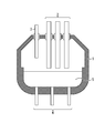
- the carburizing material is supplied from above the molten iron 5 by using a lance 3 different from the electrode 2 in an electric furnace 1 having a bottom blowing tuyere 4.
- a stirring gas is caused to flow from the bottom blowing tuyere 4 to stir the molten iron.
- the temperature of the carbon material rises and the carbonaceous material dissolves from the surface of the carbonaceous material, while the undissolved ash content causes ash content on the carbonaceous surface. It is believed that it forms a film and interferes with the contact between the carbonaceous material and the molten iron to reduce the carburizing rate.
- the main components of the ash (ASH) in the carbon material are SiO 2 and Al 2 O 3 , and when the two are combined, most of the coal types account for 70% or more of the ash, and in many cases 90%.
- the present inventors analyzed the ash film formed when such a carbon material was added upward to molten iron by an electron microscope and X-ray analysis.
- the composition of the ash film does not always match the ash composition in the carbon material.
- most of SiO 2 in ash is reduced and most of the ash film becomes a high melting point compound containing a large amount of Al 2 O 3 .
- Such compounds for example, any melting point is not less than 1800 °C Al 2 O 3, CaO ⁇ 6Al 2 O 3, components were mainly such spinel (MgO ⁇ Al 2 O 3) .
- CaO is added to the ash film and calcium silicate is formed to suppress the reduction of SiO 2 .
- the composition of the ash content film changes, approaches the composition expected from the analysis value of the carbon material and the amount of quicklime added, and the liquidus temperature decreases.
- Table 1 shows the types of carbon materials used in this experiment.
- the water content, ash content (ASH), volatile content, and fixed carbon content (% is mass%) in the carbon materials shown in Table 1 are defined by JIS M 8812:2006, and specifically, measured by the following method. Is done. Water content: Weight loss when 5 g of a sample ground to a particle size of 250 ⁇ m or less is dried at 107 ⁇ 2° C. until a constant weight is obtained. Ash (ASH): A residue (mass %) with respect to 1 g of a sample, which is a residue when 1 g of the sample is heated and ashed at 815 ⁇ 10° C.
- Volatile matter 1 g of a sample was placed in a platinum crucible with a lid, and moisture was removed from the weight loss when heated at 900 ⁇ 20°C for 7 minutes with air blocked.
- the composition of ash in the carbon material is defined by JIS M 8815:1976, and is specifically measured by the following method. Further, SiO 2 , Al 2 O 3 , and CaO represent mass% in the ash content.
- SiO 2 The sample is melted with sodium carbonate, the melt is dissolved in hydrochloric acid, treated with perchloric acid to dehydrate the silicic acid, and the precipitate is stored by filtration. The silicic acid in the filtrate is collected, combined with the main precipitate, and ignited by strong heat to give silicic acid anhydride. Hydrofluoric acid and sulfuric acid are added to this to volatilize silicon dioxide, and the reduction amount is obtained.
- Al 2 O 3 The sample is decomposed with hydrofluoric acid, nitric acid and sulfuric acid and melted with potassium pyrosulfate. The melt is dissolved in hydrochloric acid, the pH is adjusted with acetic acid and aqueous ammonia, and heavy metals are extracted and removed with DDTC and chloroform. To this, a fixed amount of EDTA standard solution is added to form EDTA-aluminum complex salt, and excess EDTA is back-titrated with zinc standard solution.
- CaO Collect the filtrate and washing solution for the determination of silicon dioxide, melt the residue after determination of silicon dioxide with sodium pyrosulfate, combine the solutions dissolved in hydrochloric acid, and add hydroxide of iron, aluminum, etc. with ammonia water. Precipitate as and filter off. The pH of the solution is adjusted, magnesium hydroxide is precipitated, interfering components are masked with potassium cyanide and titrated with EDTA standard solution using NN indicator.
- the inventors used a small melting furnace of 2 kg scale to control the bottom blowing flow rate of bottom blowing gas stirring, add a carburizing material while maintaining a predetermined molten iron temperature, and perform carburizing after adding the carburizing material.
- a speed measurement test was performed. First, quick lime powder was mixed with the six types of carbon materials shown in Table 1 to prepare a powdered carburized material. After that, electrolytic iron is melted in a small melting furnace, a carburizing material is dropped onto the molten iron surface from above, bottom blowing gas stirring is performed, sampling is performed at appropriate time intervals, and the time change of carbon concentration in molten iron is obtained.
- the capacity coefficient K defined by the equation (3) serves as an index of the reaction efficiency of the carburizing material, and the larger the capacity coefficient K, the higher the carburizing rate of the carburizing material and the better the reaction efficiency.
- the particle size of the carburized material was adjusted to a range of 1.0 ⁇ 0.4 mm by sieving.
- ⁇ 0.02 to 0.30 in the stirring power density ⁇ (kW/ton) calculated by the following formula (4).
- the range of this stirring power density was set as a range of practical values for an electric furnace or a ladle.
- Equation (4) Q: bottom blown gas total flow rate (Nm 3 /s), T: molten iron temperature (° C.), V: molten iron volume (m 3 ), ⁇ : molten iron density (kg/m 3 ), g: Gravity acceleration (m/s 2 ), L: blown gas flying height (m), P: atmosphere pressure (Pa), T n : blown gas temperature (° C.).
- L means the depth of molten iron in the small melting furnace.
- the main composition of the ash film when no quicklime powder is added is a high melting point composition containing a large amount of Al 2 O 3 , which is substantially the upper limit of the temperature normally used in an electric furnace, 1700° C., or The composition does not melt even at 1750°C.
- the ash content film is controlled to have a composition mainly composed of CaO—SiO 2 —Al 2 O 3 by mixing quicklime powder with a carbon material.
- the liquidus temperature is 1350° C. or lower.
- the composition range is extremely narrow, and while the ash composition in the carbon material varies from particle to particle, it is not possible to stably control the amount of quicklime added so that the composition will melt the ash film. Have difficulty.
- a temperature around 1400°C as a realistic temperature that can be stably applied, and evaluated it based on 1400°C.
- the temperature is higher than this, the liquid phase becomes wider with a wider composition and the viscosity also decreases, so that it is effective even at the molten iron temperature exceeding 1400° C. within the range of the addition amount of quick lime evaluated at 1400° C.
- relatively high temperature conditions such as 1600°C, the same effect may be exhibited in a wider range of the amount of quick lime added, but by making the composition such that the effect is exhibited at 1400°C, more fluidity can be obtained. It is expected to be high and a remarkable reaction promoting effect.
- the molten iron temperature is preferably 1750° C. or lower, and more preferably 1700° C. or lower. It should be noted that there may be a local high temperature field such as a fire spot due to an arc spot or a top-blown oxygen lance.
- the temperature of the reaction part should be used in principle, but in practice, there is a problem in the measurement property or uniformity of the temperature distribution, so the average molten iron temperature of the whole may be used instead.
- the ratio ( ⁇ mc+Mc ⁇ /M) of the sum of the mass (mc) of CaO and the mass (Mc) of quicklime in the ash contained in the carbon material to the mass (M) of the carburizing material is C
- the ash is
- the ratio (ms/M) of the SiO 2 mass (ms) to the carburizing material mass (M) is S
- the carburizing material mass (M) is Al 2 O 3 mass (ma) in the ash.
- the ratio (ma/M) to C is A
- C, S and A respectively represent the ratios of CaO, SiO 2 and Al 2 O 3 contained in the carburized material.
- the ratio of each component in the ash contained in the carbon material is the product of the ASH ratio in the carbon material and the ratio of each component in ASH.
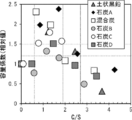
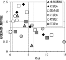
- the vertical axis represents the relative value of the capacity coefficient (K), and is a ratio with the capacity coefficient (K0) when a carbon material to which quicklime powder is not added is used, that is, K/K0.
- the relative value K/K0 of the capacity coefficient is 1.2 or less, or 1 even in the above region. There was also a condition of less than 0.5.
- the ratio C/S is 0.6 or more and 2.7 or less and the ratio C/A is 0.7 or more and 6.5 or less
- the relative value K/K0 of the capacity coefficient exceeds 1.2. Was there.
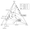
- FIG. 4 is a diagram showing the relationship between the phase diagram of the SiO 2 —CaO—Al 2 O 3 ternary system and the experimental results.
- the relative value K/K0 of the capacity coefficient exceeds 1.5, it is “a group”, and when the relative value K/K0 of the capacity coefficient is more than 1.2 and 1.5 or less, it is “b group”.
- the carbon materials to which no quicklime powder was added shown in Table 1 were classified as "d group”.
- the area of the ratio C/A of “b group” and “a group” was almost the same as the area where the composition of liquid phase exists at 1400°C.
- the region of the ratio C/S of the “b group” and the “a group” partially overlaps with the region of the composition which is in the liquid phase at 1400° C., but the regions are entirely displaced. .. In a region where the ratio C/S is smaller than 0.6, even if the composition becomes a liquid phase at 1400° C., the viscosity is high, and it is speculated that the removal of the ash film by stirring did not work effectively.
- the carburized material of the present disclosure satisfies the conditions of 0.6 ⁇ C/S ⁇ 2.7 and 0.7 ⁇ C/A ⁇ 6.5.
- the charcoal speed is significantly improved, and the effect of improving the carburization speed is particularly large in the range where the conditions of 0.6 ⁇ C/S ⁇ 1.9 and 0.7 ⁇ C/A ⁇ 5.0 are satisfied. I understood it.
- Fig. 5 and Fig. 6 show the results of changing the stirring power density for coal A in the same small furnace.
- the same C/S region and the same C/S as in the case of ⁇ 0.08 kW/t.
- An increase in the carburizing rate was confirmed in the area A. From the above results, when 0.6 ⁇ C/S ⁇ 2.7 and 0.7 ⁇ C/A ⁇ 6.5 are satisfied, preferably 0.6 ⁇ C/S ⁇ 1.9 and 0 When the condition of 0.7 ⁇ C/A ⁇ 5.0 was satisfied, the effect of improving the carburizing rate was obtained regardless of the strength of the stirring strength.
- the ratio R of quicklime contained in the carburized material when the conditions of the ratio C/S and the ratio C/A as described above are satisfied can be calculated by the following procedure.
- variable X is defined by the following expression (7).
- X (ASH)/ ⁇ 1/(C/S)+1/(C/A) ⁇ ...Equation (7)
- X monotonically increases with respect to (ASH), the ratio C/S, and the ratio C/A.
- the upper limit of the quick lime ratio R is larger as the ash ratio (ASH), the ratio C/S, and the ratio C/A are larger.
- the ratio R of quicklime in the carburized material is about 19.9% at maximum.
- the mixed powder was used as the carburizing material, but it may be a carburizing material obtained through the ingot making process such as briquetting.
- the carbon material and quick lime as an additive are closer to each other, the removal effect by the modification of the ash film becomes larger.
- the maximum particle size of the carbon material as the carburizing material is preferably 20 mm or less in order to secure the contact area with molten iron and the carburizing speed.
- the maximum particle size is not limited to 20 mm or less. It is possible to use a material having a maximum particle size of 100 mm or less.
- the lower limit of the maximum particle size of the carbon material is 0.2 mm. Preferably.
- the upper limit of the ash content in the carbon material is 18% by mass. Further, as the ash content in the carbon material is smaller, the effect of mixing quick lime is lessened, and the carbon material with less ash content is expensive, and the lower limit of ash content in the carbon material is set to 5 mass% in consideration of the cost.
- the additive to be mixed with the carbon material is quicklime whose main component is CaO. Even if CaCO 3 such as limestone is used as an additive, CO 2 is desorbed to CaO when added to the furnace and heated, so in principle the same effect as quicklime is expected. However, the actual effect is not as high as expected. The reason is that the CO 2 desorption reaction is an endothermic reaction and the carburizing reaction is also an endothermic reaction, so that heat is not sufficiently applied to the ash film and the fluidity of the ash film is insufficient, and the ash film is not effectively removed. It is thought to be because
- the CaO content in the quicklime mixed with the carbon material is preferably 80% by mass or more, and more preferably 90% by mass or more.
- the maximum particle size of the quicklime added it is preferable that the maximum particle size is 10 mm or less in order to uniformly disperse it on the surface of the carbon material and exert its effect. Further, more preferably, quicklime is in powder form and has a maximum particle size of 1 mm or less.
- an AC electric furnace is used, but if the points of supplying the carburizing material from above the molten iron surface and the fact that stirring by gas is possible are common, the AC electric furnace shown in FIG. Not limited to.
- an AC electric furnace, a DC electric furnace, or a ladle is assumed as the refining vessel for carrying out carburization under the condition that the stirring strength is weak. It should be noted that it is not assumed that carburizing is performed under the strong stirring condition using the converter type refining equipment.
- the bottom blowing gas is blown from the bottom blowing tuyere to stir the molten iron to locally expose the molten iron surface, and the carburizing material is applied to the molten iron surface. It is preferable to add so as to make direct contact. It should be noted that regardless of the bottom-blown gas species, the gas stirring method may be injection instead of bottom-blown. A solid component may be present in the molten slag layer.
- the carburizing material is supplied from the lance 3 together with the carrier gas, but the carburizing material may be supplied from a plurality of lances or may be supplied by free fall. .. Further, there may be a residual unmelted cold iron source when the carburizing material is charged. Further, the S concentration of the molten iron to be carburized is preferably 0.5 mass% or less from the viewpoint of operability at the time of removing S.
- the coefficient K was calculated.
- the lance 3 was installed immediately above one of the bottom blowing tuyere 4, the molten iron surface was exposed by stirring with the bottom blowing gas, and the carburizing material was added to the exposed portion.
- arc energization was performed under some conditions during carburization.
- the carburizing material is a mixture of a carbon material having a maximum particle diameter of 20 mm and quicklime powder having a maximum particle diameter of 1 mm (CaO content in quicklime: 90% by mass), and the carbon material is coal A shown in Table 1. , Coal C was used.
- Example 1 to 4 shown in Table 2 are conditions in which the ratio C/S and the ratio C/A satisfy the ranges of 0.6 to 2.7 and 0.7 to 6.5, respectively. In this case, all the relative values of the capacity coefficient were Y, which was a good result. Comparing Example 4 with Reference Example 8, even when using coal C with a large amount of ASH, by using the carburizing material in which the quicklime powder is mixed in an appropriate ratio, the ASH and the volatile content are less than those of the coal C. It was shown that a significant increase in carburization rate over Coal A could be achieved. In Example 3, the molten iron temperature was 1600° C., but a significant increase in the carburizing rate was confirmed by mixing quicklime powder with the carburizing material as in the case of 1500° C.
Landscapes
- Chemical & Material Sciences (AREA)
- Engineering & Computer Science (AREA)
- Materials Engineering (AREA)
- Metallurgy (AREA)
- Organic Chemistry (AREA)
- Chemical Kinetics & Catalysis (AREA)
- Mechanical Engineering (AREA)
- Manufacturing & Machinery (AREA)
- Refinement Of Pig-Iron, Manufacture Of Cast Iron, And Steel Manufacture Other Than In Revolving Furnaces (AREA)
- Treatment Of Steel In Its Molten State (AREA)
- Manufacture And Refinement Of Metals (AREA)
Abstract
Description
特許文献2:特開平1-247527号公報
特許文献3:特開2009-46726号公報
特許文献4:特開2013-72111号公報
特許文献5:特開2004-76138号公報
特許文献6:特開2003-171713号公報
特許文献7:特開2013-36056号公報
特許文献8:特開2016-151036号公報
特許文献9:特許第5803824号公報
<1> 電気炉または取鍋に収容された溶鉄に対して加炭を行う加炭材であって、
灰分が5質量%以上18質量%以下の炭素材料と生石灰との混合物であり、以下の式(1)及び式(2)の条件を満たす加炭材。
0.6≦(mc+Mc)/ms≦2.7 ・・・式(1)
0.7≦(mc+Mc)/ma≦6.5 ・・・式(2)
ここで、mcは前記炭素材料中のCaOの質量を表し、msは前記炭素材料中のSiO2の質量を表し、maは前記炭素材料中のAl2O3の質量を表し、Mcは前記生石灰の質量を表す。
<2> 前記混合物が、以下の式(1A)及び式(2A)の条件を満たす<1>に記載の加炭材。
0.6≦(mc+Mc)/ms≦1.9 ・・・式(1A)
0.7≦(mc+Mc)/ma≦5.0 ・・・式(2A)
<3> 上記<1>に記載の加炭材を用いた加炭方法であって、前記電気炉または前記取鍋において、ガスを吹き込んで前記溶鉄を攪拌して形成された溶鉄面に向けて、前記加炭材を添加して加炭を行う加炭方法。
<4> 前記加炭材を、前記溶鉄面に向けてランスから投入することにより添加する<3>に記載の加炭方法。
図1に示すように、溶鉄へ加炭を行う場合は、底吹き羽口4付きの電気炉1において、電極2とは別のランス3を用いて溶鉄5の上方から加炭材を供給し、底吹き羽口4から撹拌ガスを流して溶鉄の攪拌を行う。
本発明者らは、このような炭素材料を溶鉄に上方添加した際に形成される灰分膜を電子顕微鏡およびX線分析により解析した。その結果、灰分膜の組成は炭素材料中の灰分組成とは必ずしも一致しないことを知見した。特に灰分中のSiO2は大部分が還元され、灰分膜の多くはAl2O3を多く含む高融点の化合物となることを知見した。このような化合物は、例えば融点がいずれも1800℃以上のAl2O3、CaO・6Al2O3、スピネル(MgO・Al2O3)といった成分が主であった。さらに、生石灰粉を炭素材料に予め添加し混合した加炭材を用いると、灰分膜中にCaOが加わるとともにカルシウムシリケートを形成してSiO2の還元が抑制される。これにより、灰分膜の組成が変化し、炭素材料の分析値と添加した生石灰の量から予想される組成に近付き、液相線温度が低くなる方向に変化することを知見した。

水分:250μm以下の粒径に粉砕した試料5gを107±2℃で恒量になるまで乾燥した時の減量。
灰分(ASH):試料1gを815±10℃で加熱灰化したときの残渣で試料1gに対しての割合(質量%)。
揮発分:試料1gを蓋つき白金坩堝に入れ、900±20℃で7分間空気を遮断して加熱した時の減量から水分を除いたもの。
固定炭素分:固定炭素分[質量%]=100-(水分[質量%]+灰分[質量%]+揮発分[質量%])。
SiO2:試料を炭酸ナトリウムで融解し、融成物を塩酸に溶解し、過塩素酸処理をしてケイ酸を脱水し、ろ過して沈殿は保存する。ろ液中のケイ酸を回収して主沈殿に合わせ、強熱灰化して無水ケイ酸とし,これにフッ化水素酸と硫酸とを加えて二酸化ケイ素を揮散させ、その減量を求める。
Al2O3:試料をフッ化水素酸,硝酸及び硫酸で分解し、ピロ硫酸カリウムで融解する。融成物を塩酸に溶解し、酢酸及びアンモニア水でpHを調節し、DDTCとクロロホルムで重金属を抽出除去する。これにEDTA標準溶液の一定量を加え、EDTA-アルミニウム錯塩を生成させ、過剰のEDTAを亜鉛標準溶液で逆滴定する。
CaO:二酸化ケイ素定量時のろ液及び洗液を集め、これに二酸化ケイ素定量後の残渣をピロ硫酸ナトリウムで融解し、塩酸に溶解した溶液を合わせ、アンモニア水で鉄、アルミニウムなどを水酸化物として沈殿し、ろ別する。溶液のpHを調節し、水酸化マグネシウムを沈殿させ、シアン化カリウムにより妨害成分をマスクしてNN指示薬を用い、EDTA標準溶液で滴定する。
ln((CS-C0)/(CS-Ct))=K×t ・・・式(3)
ε=371×Q×(T+273)/V×{ln(1+ρ×g×L/P)+1-(Tn+273)/(T+273)} ・・・式(4)
式(4)において、Q:底吹きガス合計流量(Nm3/s)、T:溶鉄温度(℃)、V:溶鉄体積(m3)、ρ:溶鉄密度(kg/m3)、g:重力加速度(m/s2)、L:吹き込みガスの浮上高さ(m)、P:雰囲気の圧力(Pa)、Tn:吹込みガス温度(℃)である。小型溶解炉の試験において、Lは小型溶解炉の溶鉄深さを意味する。
ms+ma≦M×(1-R)×(ASH) ・・・式(5)
さらに、式(5)の両辺にC/(ms+ma)を乗算し、R≦Cの関係を用いると、以下の式(6)が得られる。
R≦C≦(1-R)×(ASH)/{1/(C/S)+1/(C/A)} ・・・式(6)
X=(ASH)/{1/(C/S)+1/(C/A)} ・・・式(7)
この場合、Xは(ASH)、比率C/S、比率C/Aに対してそれぞれ単調増加である。
式(6)を変形し、式(7)を代入すると、以下の式(8)が得られる。
R≦1/(1+1/X) ・・・式(8)
炭素材料と混合する生石灰におけるCaO含有量は、80質量%以上であることが好ましく、90質量%以上であることがより好ましい。
表2の「判定」については、生石灰粉を混合したこと以外は同じ条件(同一炭種、同一温度)の参考例と比較して、比較する参考例の容量係数K0を1.0とした場合の相対値K/K0が1.0を超えれば、生石灰粉を混合したことで加炭速度が向上したと考えられる。容量係数の相対値K/K0が1.2を超える場合に加炭速度が有意に向上したと判断してY(合格)とし、1.2以下の場合は有意な向上は見られないと判断してN(不合格)とした。具体的には、実施例3は参考例9と比較し、実施例4は参考例8と比較し、それ以外は参考例7と比較した。

2 電極
3 ランス
4 底吹き羽口
5 溶鉄
Claims (4)
- 電気炉または取鍋に収容された溶鉄に対して加炭を行う加炭材であって、
灰分が5質量%以上18質量%以下の炭素材料と生石灰との混合物であり、以下の式(1)及び式(2)の条件を満たす加炭材。
0.6≦(mc+Mc)/ms≦2.7 ・・・式(1)
0.7≦(mc+Mc)/ma≦6.5 ・・・式(2)
ここで、mcは前記炭素材料中のCaOの質量を表し、msは前記炭素材料中のSiO2の質量を表し、maは前記炭素材料中のAl2O3の質量を表し、Mcは前記生石灰の質量を表す。 - 前記混合物が、以下の式(1A)及び式(2A)の条件を満たす請求項1に記載の加炭材。
0.6≦(mc+Mc)/ms≦1.9 ・・・式(1A)
0.7≦(mc+Mc)/ma≦5.0 ・・・式(2A) - 請求項1又は請求項2に記載の加炭材を用いた加炭方法であって、
前記電気炉または前記取鍋において、ガスを吹き込んで前記溶鉄を攪拌して形成された溶鉄面に向けて、前記加炭材を添加して加炭を行う加炭方法。 - 前記加炭材を、前記溶鉄面に向けてランスから投入することにより添加する請求項3に記載の加炭方法。
Priority Applications (6)
| Application Number | Priority Date | Filing Date | Title |
|---|---|---|---|
| US17/293,053 US20210404047A1 (en) | 2018-12-07 | 2019-12-06 | Carburizer and carburization method using the same |
| CN201980075578.4A CN113056566B (zh) | 2018-12-07 | 2019-12-06 | 增碳材及使用了其的增碳方法 |
| KR1020217015523A KR102517013B1 (ko) | 2018-12-07 | 2019-12-06 | 가탄재 및 그것을 사용한 가탄 방법 |
| BR112021010228-0A BR112021010228B1 (pt) | 2018-12-07 | 2019-12-06 | Carburador que realiza carburação com respeito a ferro fundido acomodado em um forno elétrico ou uma panela de fundição, e, método de carburação que usa o carburador |
| JP2020560074A JP6954481B2 (ja) | 2018-12-07 | 2019-12-06 | 加炭材およびそれを用いた加炭方法 |
| US19/366,530 US20260043120A1 (en) | 2018-12-07 | 2025-10-23 | Carburizer and carburization method using the same |
Applications Claiming Priority (2)
| Application Number | Priority Date | Filing Date | Title |
|---|---|---|---|
| JP2018-230108 | 2018-12-07 | ||
| JP2018230108 | 2018-12-07 |
Related Child Applications (2)
| Application Number | Title | Priority Date | Filing Date |
|---|---|---|---|
| US17/293,053 A-371-Of-International US20210404047A1 (en) | 2018-12-07 | 2019-12-06 | Carburizer and carburization method using the same |
| US19/366,530 Division US20260043120A1 (en) | 2018-12-07 | 2025-10-23 | Carburizer and carburization method using the same |
Publications (1)
| Publication Number | Publication Date |
|---|---|
| WO2020116643A1 true WO2020116643A1 (ja) | 2020-06-11 |
Family
ID=70975536
Family Applications (1)
| Application Number | Title | Priority Date | Filing Date |
|---|---|---|---|
| PCT/JP2019/047930 Ceased WO2020116643A1 (ja) | 2018-12-07 | 2019-12-06 | 加炭材およびそれを用いた加炭方法 |
Country Status (7)
| Country | Link |
|---|---|
| US (2) | US20210404047A1 (ja) |
| JP (1) | JP6954481B2 (ja) |
| KR (1) | KR102517013B1 (ja) |
| CN (1) | CN113056566B (ja) |
| BR (1) | BR112021010228B1 (ja) |
| TW (1) | TW202035706A (ja) |
| WO (1) | WO2020116643A1 (ja) |
Cited By (1)
| Publication number | Priority date | Publication date | Assignee | Title |
|---|---|---|---|---|
| JP2023068357A (ja) * | 2021-11-02 | 2023-05-17 | 日本製鉄株式会社 | 溶鋼処理炉の操業方法および溶鋼処理炉の副原料 |
Families Citing this family (2)
| Publication number | Priority date | Publication date | Assignee | Title |
|---|---|---|---|---|
| CN114293141B (zh) * | 2022-01-07 | 2023-01-24 | 江苏优耐思机器人科技有限公司 | 一种高效电弧渗碳自动化设备 |
| WO2025192356A1 (ja) * | 2024-03-15 | 2025-09-18 | Jfeスチール株式会社 | 溶鉄の精錬方法 |
Citations (2)
| Publication number | Priority date | Publication date | Assignee | Title |
|---|---|---|---|---|
| JP2000212630A (ja) * | 1999-01-20 | 2000-08-02 | Nk Matekku Kk | 電気炉ダスト含有製鋼用加炭材の製造方法及びそれにより得られる製鋼用加炭材並びに電気炉ダストのリサイクル方法 |
| JP2017186607A (ja) * | 2016-04-05 | 2017-10-12 | Jfe条鋼株式会社 | 電気炉精錬方法 |
Family Cites Families (18)
| Publication number | Priority date | Publication date | Assignee | Title |
|---|---|---|---|---|
| JPS583824B2 (ja) | 1974-06-10 | 1983-01-22 | テイジンカセイ カブシキガイシヤ | ネツカソセイジユシヒフクボウジヨウタイ |
| JPS6043888B2 (ja) | 1978-09-13 | 1985-10-01 | 日本坩堝株式会社 | 製鉄、製鋼用加炭材 |
| CA1281551C (en) * | 1985-02-18 | 1991-03-19 | Kazuhiro Kinoshita | Method for addition of low-melting point metal |
| JPH01247527A (ja) | 1988-03-29 | 1989-10-03 | Riken Kasei Kk | 炭素濃度調整方法 |
| US5588982A (en) * | 1995-05-01 | 1996-12-31 | Alabama Power Company | Process for producing foudry iron |
| US6251156B1 (en) * | 1998-10-30 | 2001-06-26 | Midrex Technologies, Inc. | Method of producing molten iron in duplex furnaces |
| JP2001355014A (ja) * | 2000-06-13 | 2001-12-25 | Nippon Steel Corp | 含鉄冷材の溶解方法 |
| CN1309844C (zh) * | 2000-12-19 | 2007-04-11 | Posco公司 | 一种用于熔炼还原炼铁的煤饼 |
| JP3750928B2 (ja) | 2001-12-06 | 2006-03-01 | 昭和電炉興業株式会社 | 加炭材およびそれを用いた製鋼方法 |
| JP2004076138A (ja) | 2002-08-22 | 2004-03-11 | Osaka Koukai Kk | スクラップからの溶銑生成用造塊無煙炭 |
| JP2009046726A (ja) | 2007-08-20 | 2009-03-05 | Jp Steel Plantech Co | アーク炉製鋼方法 |
| JP5297173B2 (ja) * | 2008-12-09 | 2013-09-25 | 株式会社神戸製鋼所 | フェロモリブデンの製造方法 |
| JP2013036056A (ja) | 2011-08-03 | 2013-02-21 | Nippon Steel & Sumitomo Metal Corp | 溶鋼中炭素濃度の調整方法 |
| JP5870584B2 (ja) | 2011-09-28 | 2016-03-01 | Jfeスチール株式会社 | 溶銑の脱燐処理方法 |
| JP5408369B2 (ja) * | 2012-01-19 | 2014-02-05 | Jfeスチール株式会社 | 溶銑の予備処理方法 |
| KR101561279B1 (ko) * | 2013-11-28 | 2015-10-26 | 주식회사 포스코 | 용철제조방법 및 용철제조장치 |
| KR101739858B1 (ko) * | 2014-12-18 | 2017-05-25 | 주식회사 포스코 | 성형탄, 이의 제조 방법 및 장치 |
| JP6458531B2 (ja) | 2015-02-17 | 2019-01-30 | 新日鐵住金株式会社 | アーク式底吹き電気炉における撹拌方法 |
-
2019
- 2019-12-06 JP JP2020560074A patent/JP6954481B2/ja active Active
- 2019-12-06 KR KR1020217015523A patent/KR102517013B1/ko active Active
- 2019-12-06 BR BR112021010228-0A patent/BR112021010228B1/pt active IP Right Grant
- 2019-12-06 US US17/293,053 patent/US20210404047A1/en not_active Abandoned
- 2019-12-06 WO PCT/JP2019/047930 patent/WO2020116643A1/ja not_active Ceased
- 2019-12-06 TW TW108144781A patent/TW202035706A/zh unknown
- 2019-12-06 CN CN201980075578.4A patent/CN113056566B/zh active Active
-
2025
- 2025-10-23 US US19/366,530 patent/US20260043120A1/en active Pending
Patent Citations (2)
| Publication number | Priority date | Publication date | Assignee | Title |
|---|---|---|---|---|
| JP2000212630A (ja) * | 1999-01-20 | 2000-08-02 | Nk Matekku Kk | 電気炉ダスト含有製鋼用加炭材の製造方法及びそれにより得られる製鋼用加炭材並びに電気炉ダストのリサイクル方法 |
| JP2017186607A (ja) * | 2016-04-05 | 2017-10-12 | Jfe条鋼株式会社 | 電気炉精錬方法 |
Cited By (2)
| Publication number | Priority date | Publication date | Assignee | Title |
|---|---|---|---|---|
| JP2023068357A (ja) * | 2021-11-02 | 2023-05-17 | 日本製鉄株式会社 | 溶鋼処理炉の操業方法および溶鋼処理炉の副原料 |
| JP7799168B2 (ja) | 2021-11-02 | 2026-01-15 | 日本製鉄株式会社 | 溶鋼処理炉の操業方法および溶鋼処理炉の副原料 |
Also Published As
| Publication number | Publication date |
|---|---|
| CN113056566A (zh) | 2021-06-29 |
| JP6954481B2 (ja) | 2021-10-27 |
| BR112021010228B1 (pt) | 2023-12-05 |
| CN113056566B (zh) | 2024-03-15 |
| BR112021010228A2 (pt) | 2021-08-24 |
| KR102517013B1 (ko) | 2023-04-04 |
| TW202035706A (zh) | 2020-10-01 |
| KR20210079354A (ko) | 2021-06-29 |
| US20210404047A1 (en) | 2021-12-30 |
| US20260043120A1 (en) | 2026-02-12 |
| JPWO2020116643A1 (ja) | 2021-09-02 |
Similar Documents
| Publication | Publication Date | Title |
|---|---|---|
| JP5408369B2 (ja) | 溶銑の予備処理方法 | |
| JP5954551B2 (ja) | 転炉製鋼法 | |
| US20260043120A1 (en) | Carburizer and carburization method using the same | |
| JP5408379B2 (ja) | 溶銑の予備処理方法 | |
| JPH0215130A (ja) | 含亜鉛冶金ダストおよびスラッジの利用方法 | |
| RU2258083C1 (ru) | Способ выплавки рельсовой стали | |
| JPS6164807A (ja) | 鉄鉱石の溶融還元方法 | |
| JP2018178235A (ja) | 溶銑の予備処理方法 | |
| JP2014101542A (ja) | 溶銑の脱銅処理方法 | |
| JP3888313B2 (ja) | スロッピング防止方法 | |
| JP4329724B2 (ja) | 転炉スクラップ増配方法 | |
| RU2107738C1 (ru) | Способ выплавки стали из металлолома в дуговой электропечи | |
| JP4639943B2 (ja) | 溶銑の脱硫方法 | |
| KR101863916B1 (ko) | 마그네슘 제련공정 부산물과 알루미늄 제련공정 폐부산물을 이용한 탈황 및 탈산용 제강플럭스 조성물 | |
| JP3750928B2 (ja) | 加炭材およびそれを用いた製鋼方法 | |
| JP2006009146A (ja) | 溶銑の精錬方法 | |
| JP2020100889A (ja) | 溶銑の脱硫方法 | |
| JP3645620B2 (ja) | 溶銑の予備処理方法 | |
| WO1997012066A1 (en) | Chromium ore smelting reduction process | |
| JPH0826382B2 (ja) | 溶銑の予備処理方法 | |
| JP3858630B2 (ja) | 溶融鉄合金の脱硫方法 | |
| SU1157107A1 (ru) | Способ выплавки углеродистого ферромарганца из бедных руд | |
| CN115852079A (zh) | 一种kr脱硫物质及kr脱硫方法 | |
| JPH01252715A (ja) | 鉄浴式溶融還元炉の操業方法 | |
| JP2022189300A (ja) | 溶鉄への加炭方法 |
Legal Events
| Date | Code | Title | Description |
|---|---|---|---|
| 121 | Ep: the epo has been informed by wipo that ep was designated in this application |
Ref document number: 19894347 Country of ref document: EP Kind code of ref document: A1 |
|
| ENP | Entry into the national phase |
Ref document number: 2020560074 Country of ref document: JP Kind code of ref document: A |
|
| ENP | Entry into the national phase |
Ref document number: 20217015523 Country of ref document: KR Kind code of ref document: A |
|
| NENP | Non-entry into the national phase |
Ref country code: DE |
|
| REG | Reference to national code |
Ref country code: BR Ref legal event code: B01A Ref document number: 112021010228 Country of ref document: BR |
|
| ENP | Entry into the national phase |
Ref document number: 112021010228 Country of ref document: BR Kind code of ref document: A2 Effective date: 20210526 |
|
| 122 | Ep: pct application non-entry in european phase |
Ref document number: 19894347 Country of ref document: EP Kind code of ref document: A1 |