WO2020111247A1 - 丸鋼材のマーキング検出装置及び検出方法及び鋼材の製造方法 - Google Patents
丸鋼材のマーキング検出装置及び検出方法及び鋼材の製造方法 Download PDFInfo
- Publication number
- WO2020111247A1 WO2020111247A1 PCT/JP2019/046841 JP2019046841W WO2020111247A1 WO 2020111247 A1 WO2020111247 A1 WO 2020111247A1 JP 2019046841 W JP2019046841 W JP 2019046841W WO 2020111247 A1 WO2020111247 A1 WO 2020111247A1
- Authority
- WO
- WIPO (PCT)
- Prior art keywords
- marking
- steel material
- round steel
- image
- circumferential direction
- Prior art date
- Legal status (The legal status is an assumption and is not a legal conclusion. Google has not performed a legal analysis and makes no representation as to the accuracy of the status listed.)
- Ceased
Links
Images




Classifications
-
- B—PERFORMING OPERATIONS; TRANSPORTING
- B21—MECHANICAL METAL-WORKING WITHOUT ESSENTIALLY REMOVING MATERIAL; PUNCHING METAL
- B21B—ROLLING OF METAL
- B21B38/00—Methods or devices for measuring, detecting or monitoring specially adapted for metal-rolling mills, e.g. position detection, inspection of the product
-
- B—PERFORMING OPERATIONS; TRANSPORTING
- B21—MECHANICAL METAL-WORKING WITHOUT ESSENTIALLY REMOVING MATERIAL; PUNCHING METAL
- B21C—MANUFACTURE OF METAL SHEETS, WIRE, RODS, TUBES, PROFILES OR LIKE SEMI-MANUFACTURED PRODUCTS OTHERWISE THAN BY ROLLING; AUXILIARY OPERATIONS USED IN CONNECTION WITH METAL-WORKING WITHOUT ESSENTIALLY REMOVING MATERIAL
- B21C37/00—Manufacture of metal sheets, rods, wire, tubes, profiles or like semi-manufactured products, not otherwise provided for; Manufacture of tubes of special shape
- B21C37/04—Manufacture of metal sheets, rods, wire, tubes, profiles or like semi-manufactured products, not otherwise provided for; Manufacture of tubes of special shape of rods or wire
-
- B—PERFORMING OPERATIONS; TRANSPORTING
- B21—MECHANICAL METAL-WORKING WITHOUT ESSENTIALLY REMOVING MATERIAL; PUNCHING METAL
- B21C—MANUFACTURE OF METAL SHEETS, WIRE, RODS, TUBES, PROFILES OR LIKE SEMI-MANUFACTURED PRODUCTS OTHERWISE THAN BY ROLLING; AUXILIARY OPERATIONS USED IN CONNECTION WITH METAL-WORKING WITHOUT ESSENTIALLY REMOVING MATERIAL
- B21C51/00—Measuring, gauging, indicating, counting, or marking devices specially adapted for use in the production or manipulation of material in accordance with subclasses B21B - B21F
-
- B—PERFORMING OPERATIONS; TRANSPORTING
- B23—MACHINE TOOLS; METAL-WORKING NOT OTHERWISE PROVIDED FOR
- B23Q—DETAILS, COMPONENTS, OR ACCESSORIES FOR MACHINE TOOLS, e.g. ARRANGEMENTS FOR COPYING OR CONTROLLING; MACHINE TOOLS IN GENERAL CHARACTERISED BY THE CONSTRUCTION OF PARTICULAR DETAILS OR COMPONENTS; COMBINATIONS OR ASSOCIATIONS OF METAL-WORKING MACHINES, NOT DIRECTED TO A PARTICULAR RESULT
- B23Q17/00—Arrangements for observing, indicating or measuring on machine tools
- B23Q17/24—Arrangements for observing, indicating or measuring on machine tools using optics or electromagnetic waves
-
- B—PERFORMING OPERATIONS; TRANSPORTING
- B24—GRINDING; POLISHING
- B24B—MACHINES, DEVICES, OR PROCESSES FOR GRINDING OR POLISHING; DRESSING OR CONDITIONING OF ABRADING SURFACES; FEEDING OF GRINDING, POLISHING, OR LAPPING AGENTS
- B24B27/00—Other grinding machines or devices
- B24B27/033—Other grinding machines or devices for grinding a surface for cleaning purposes, e.g. for descaling or for grinding off flaws in the surface
-
- G—PHYSICS
- G01—MEASURING; TESTING
- G01B—MEASURING LENGTH, THICKNESS OR SIMILAR LINEAR DIMENSIONS; MEASURING ANGLES; MEASURING AREAS; MEASURING IRREGULARITIES OF SURFACES OR CONTOURS
- G01B11/00—Measuring arrangements characterised by the use of optical techniques
Definitions
- the present invention a marking detection device and a detection method for a round steel material, in particular, a round billet, a round bar steel, a steel pipe, etc., a marking applied to the position of a surface flaw existing on the surface of a long round steel material having a circular cross section.
- the present invention also relates to a method for manufacturing a steel material, and more particularly to a method for manufacturing a steel material including grinding a surface flaw using the above-described marking detection method.
- round steel slabs with a circular cross section are manufactured directly by casting, or by slabbing the cast steel slabs.
- the round steel slab often has some kind of flaw (casting flaw, hole, linear flaw, cut flaw, etc.) on its surface in the manufacturing process. These flaws become an obstacle in the later process. That is, for example, in the case of hot rolling a round steel slab, flaws caused by these defect parts may remain in the steel material after hot rolling, or fracture of the steel material may occur during hot rolling. Failures such as relaxation occur. Therefore, a so-called “maintenance work” is carried out to grind and remove the surface flaws before the round steel pieces are sent to the subsequent process. Further, since surface steel products such as round steel bars and product steel pipes may also have surface flaws in the manufacturing process, maintenance work is also performed on round steel products such as steel bar products and product steel pipes.
- Patent Document 1 As a conventional surface flaw care device for round steel products, for example, one shown in Patent Document 1 is known.
- the surface flaw maintenance device for a round steel material shown in Patent Document 1 is reciprocally movable along the axial direction of a rotating round steel material, and is detected as a surface flaw inspection device for detecting a surface flaw in contact with the round steel material. It is provided with a marking device for injecting a marking liquid at a position of a surface flaw to make a mark, and a work deck for caring for the marked surface flaw.
- a marking device for injecting a marking liquid at a position of a surface flaw to make a mark
- a work deck for caring for the marked surface flaw.
- the conventional surface flaw care device for a round steel material disclosed in Patent Document 1 has the following problems. That is, in the case of the round steel surface flaw care device shown in Patent Document 1, the operator visually finds the marking applied to the detected position of the surface flaw, and grinds the spot.
- the marking applied to the position of the surface flaw of the round steel material may change its size and shape depending on the spraying condition of the marking liquid, and it may be difficult for the operator to find it visually. Therefore, the method of finding the marking by the operator's eyes has a problem that the risk of missing the marking is large and the grinding efficiency is low. Further, this problem has led to the problem that the manufacturing efficiency is low in the steel material manufacturing method in which the method of visually finding the marking is incorporated as one step in the series of steel material manufacturing processes.
- the present invention has been made in order to solve this conventional problem, and its purpose is to detect a marking automatically and thereby significantly reduce the risk of missing a marking.
- Another object of the present invention is to provide a detection method and a steel material manufacturing method using the detection method.
- a marking detection device for a round steel material is a marking detection device for a round steel material, which detects a marking applied to a position of a surface flaw of the round steel material, in a circumferential direction.
- An image pickup device that picks up a specific position in the circumferential direction of the surface of the round steel material that rotates in a predetermined cycle with a resolution smaller than the dimension of the marking to be measured, and an image of the specific position picked up by the image pickup device.
- the gist of the present invention is to include an image processing unit that processes an image obtained by joining in a direction and a marking extraction unit that extracts a marking from the image processed by the image processing unit.
- a marking detection method for a round steel material is a marking detection method for a round steel material, which detects a marking applied to a position of a surface flaw of the round steel material, wherein the circle rotating in the circumferential direction is used.
- the gist is to include an image processing step of processing the obtained image and a marking extraction step of extracting a marking from the image subjected to the image processing in the image processing step.
- a method for manufacturing a steel material according to another aspect of the present invention is to detect a defective portion of a round steel material, apply a marking to a portion having a defective portion having a predetermined depth or more found by the inspection, and then apply it.
- a method for manufacturing a steel material which comprises detecting a marking and grinding the surface of the detected marking and then performing a treatment in a post-process, wherein the marking is detected by the marking detecting method according to the aspect of the present invention described above. That is the summary.
- the marking detection apparatus and the detection method of the round steel material which concern on this invention, the marking detection apparatus and detection method of the round steel material which detected the marking automatically, and greatly reduced the risk of missing the marking, and manufacturing of the steel material.
- a method can be provided.
- An example of the image after the original image joining process, the binarized image after removal of the binarized noise, and the image of the marking extraction result is displayed from one end face in the axial direction of the round steel material to the first position in the axial direction. It is the figure divided and shown in three from the 1st position to the 2nd position and the said 2nd position to the 3rd position. It is a figure which shows a part of example of the binarized image after a binarized noise removal process. It is the figure which looked at the schematic structure of the marking detection device of the round steel material concerning another embodiment of the present invention from the front side.
- FIG. 1 shows a schematic configuration of a marking detection device for a round steel material according to an embodiment of the present invention.
- a marking detection device 1 for a round steel material is a marking device for marking a position of a surface flaw of a round steel material S. It is installed on the downstream side (not shown). The marking device is provided in the middle of a transportation line that conveys the round steel material S to the downstream process. The marking device applies the marking to the position of the surface flaw of the round steel material S, and the round steel material S to which the marking is applied is transferred. It is transferred to the marking detection device 1 by (not shown).
- the marking device is provided in association with a flaw detection device such as a leakage magnetic flux flaw detector (MLFT) or an ultrasonic flaw detector (AUT) that detects a defect on the surface or in the vicinity of the surface. Then, the marking device applies the paint to a portion of the round steel material S where there is a defect having a predetermined depth or more found by the flaw detection device to make marking.
- a flaw detection device such as a leakage magnetic flux flaw detector (MLFT) or an ultrasonic flaw detector (AUT) that detects a defect on the surface or in the vicinity of the surface.
- the marking device applies the paint to a portion of the round steel material S where there is a defect having a predetermined depth or more found by the flaw detection device to make marking.
- the size of the marked round steel material S is any size between the minimum diameter ⁇ 80 mm and the maximum diameter ⁇ 450 mm, and in FIG. 1 to FIG. , The minimum diameter round steel material is indicated by S2.
- the color of the marking applied to the position of the surface flaw of the round steel material S by the marking device is preferably different from the color of the illumination by the illumination device 5 described later (a color similar to white).
- the marking color and the illumination color are not confused with each other, and the marking can be easily detected.
- the marking detection device 1 detects the marking M (see FIG. 8) applied to the position of the surface flaw of the round steel material S, and moves the round steel material S transferred by the transfer to a predetermined rotation speed (in the present embodiment).
- a predetermined rotation speed in the present embodiment.
- the turning roller 2 is provided with a pulse generator 17 as a rotation angle detection device that detects the rotation angle of the round steel material S.
- the rotation number of the turning roller 2 is input from the pulse generator 17 to the marking extraction unit 9 to be described later, and the marking extraction unit 9 determines the rotation angle from the imaging start point of the round steel material S based on the input rotation number of the turning roller 2. To detect.
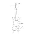
- the marking detection device 1 includes a plurality of image pickup devices 3 for picking up an image of the surface of the round steel material S that rotates on the turning roller 2 in the circumferential direction, a computer system 7, and a display device 10.
- a plurality of first support members 13 are attached to a plurality of support legs 12 erected on a pedestal portion 11 so as to be orthogonal to the support legs 12.
- the second support member 14 is attached to the first support member 13 so as to be orthogonal to the first support member 13.
- a plurality of third support members 15 are attached so as to be orthogonal to the support legs 12 at positions above the portions of the plurality of support legs 12 to which the first support members 13 are attached.
- a fourth support member 16 is attached to the third support member 15 so as to be orthogonal to the third support member 15.
- Each imaging device 3 is attached to the tip of the fourth support member 16.
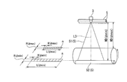
- Each imaging device 3 is composed of a line sensor camera. As shown in FIG. 2, the direction in which the imaging line of the line sensor camera extends and the axial direction of the round steel material S coincide with each other, and as shown in FIG.
- the sensor camera is installed so that the angle ⁇ formed by the optical axis L3 and the tangent line TL in contact with the uppermost position P of the round steel material S is 90 degrees.
- the angle ⁇ formed by the optical axis L3 and the tangent line TL is not limited to 90 degrees, and it is preferable that the acute side has a range of 30 degrees or more.
- the installation height of the line sensor cameras constituting each imaging device 3 is such that the distance WD between the lens of the line sensor camera and the round steel material S is a predetermined distance (of the round steel material S1 having the maximum diameter).
- the distance WD( ⁇ max) 900 mm
- the distance WD( ⁇ min) 1270 mm.
- a camera having a lens in focus is selected.
- the depth of field is set to 771 mm, and a lens that is in focus is selected regardless of whether the diameter of the round steel material S1 having the maximum diameter is ⁇ 450 mm and the diameter of the round steel material S2 having the minimum diameter is ⁇ 80 mm.
- each image pickup device 3 has a marking M (FIG. 8) that is a measurement target at the uppermost position (specific position) P in the circumferential direction of the surface of the round steel material S that rotates on the turning roller 2 in the circumferential direction.
- An image of one round of the round steel material S is picked up at a predetermined cycle with a resolution smaller than the dimension of (see).
- the uppermost position P of the surface of the round steel S that rotates in the circumferential direction (the uppermost position of the surface of the round steel S1 having the largest diameter is P1, the uppermost position of the surface of the round steel S2 having the smallest diameter is P2).
- the size of the marking M is a circle having a diameter of about 4 mm
- the resolution of the line sensor camera that is, the width R in the circumferential direction of each pixel n (see FIG. 3) of one line is the maximum diameter circle.
- the width R ( ⁇ max) in the circumferential direction of each pixel n when imaging the steel material S1 is 630 ⁇ m/pix
- the width R ( ⁇ min) in the circumferential direction of each pixel n when imaging the round steel material S2 having the minimum diameter is 889 ⁇ m/ It is pix.
- the cycle of imaging with the line sensor camera is 1/2381 s so that the rotation speed of the round steel material S is 1500 mm/s and the circumferential surface of the round steel material S can be imaged without gaps. Is becoming
- the number of pixels n of one line of the line sensor camera constituting each imaging device 3 is 2048 pix
- the axial width R ( ⁇ max) of each pixel n when imaging the round steel S1 having the maximum diameter is 630 ⁇ m/ Pix
- the width R ( ⁇ min) in the axial direction of each pixel n when imaging the round steel material S2 having the smallest diameter is 889 ⁇ m/pix. Therefore, the visual field width L ( ⁇ max) when capturing the maximum diameter round steel material S1 is 1290 mm
- the visual field width L ( ⁇ min) when capturing the minimum diameter round steel material S2 is 1821 mm.
- a plurality of imaging devices 3 are installed along the axial direction of the round steel material S so that the entire length of the round steel material S1 having the maximum diameter and the total length of the round steel material S2 having the minimum diameter can be imaged.
- the reason why the imaging device 3 is a line sensor camera whose imaging line extends in the axial direction of the round steel material S is as follows. That is, when the round steel material S is viewed from the axial direction, the surface of the round steel material S is circular. Therefore, when the imaging device 3 is an area sensor camera, the distance from the area sensor camera to the surface of the round steel material S is large. Are different along the circumferential direction, and the angle between the position on the surface of the round steel S when viewed from the axial direction of the round steel S and the straight line connecting the camera with the surface of the round steel S at this position is the circumferential direction. Different along.
- the imaging device 3 is an area sensor camera
- the appearance of the shape of the marking applied to the surface of the round steel material S in the captured image changes along the circumferential direction of the round steel material S.
- the straight line connecting the position on the surface of the round steel material S and the camera forms an acute angle with the surface of the round steel material at this position
- the area of the marking in the captured image becomes small, and it is difficult to distinguish between the marking and noise.
- the image pickup device 3 is composed of a line sensor camera, and the image pickup device 3 is arranged so that the image pickup line extends in the axial direction of the round steel material S, and the position of the uppermost position P on the surface of the round steel material S rotating in the circumferential direction is set. Images are taken along the axial direction.
- the image at the uppermost position (specific position) P captured by the line sensor camera is taken as an image obtained by joining the images in the circumferential direction, and the marking is extracted from this image.
- the distance from the line sensor camera to the position of the uppermost position P on the surface of the round steel S does not change, and the line connecting the camera and the uppermost position P is not changed.
- the angle formed by the surface of the round steel S at the uppermost position P is constant. Therefore, by using the image pickup device 3 as a line sensor camera, it is possible to appropriately detect the shape of the marking applied to the surface of the round steel S that is the image pickup target.
- Each imaging device 3 is connected to a camera control device 4 that controls a power supply, an imaging cycle, and the like, which are not shown.
- the marking detection device 1 includes a plurality of illumination devices 5 as shown in FIGS. 1 to 3.
- Each lighting device 5 is rotatably attached to the tip of the second support member 14 described above.
- Each illuminating device 5 is composed of two rows of bar illuminators that continuously illuminate the surface of the round steel material S, especially near the uppermost position P where an image is taken. The color of the illumination is close to white.
- the angle ⁇ formed by the optical axis L5 of the lighting device 5 and the vertical line VL is from the vicinity of the uppermost position P2 of the round steel material S2 having the smallest diameter to the uppermost position P1 of the round steel material S1 having the largest diameter.
- a plurality of lighting devices 5 are installed along the axial direction of the round steel S so that the entire length of the round steel S1 having the maximum diameter and the total length of the round steel S2 having the minimum diameter can be illuminated.
- Each lighting device 5 is connected to a lighting power supply (not shown) and a lighting control device 6 that controls the brightness of the lighting and the like.
- the computer system 7 includes an image processing unit 8 that processes an image obtained by joining the images at the above-described uppermost position (specific position) P captured by each imaging device 3 in the circumferential direction, and the image processing unit 8.
- the marking extraction unit 9 is provided for extracting the marking M (see FIG. 8) from the image processed in (1).
- Each image pickup device 3 and the pulse generator 17 are connected to the computer system 7.
- the computer system 7 is a computer system having an arithmetic processing function for realizing each function of the image processing unit 8 and the marking extraction unit 9 by executing a program on computer software.
- the computer system is configured to include a ROM, a RAM, a CPU, and the like, and executes the various dedicated programs stored in the ROM or the like in advance to realize the above-described functions on software.
- the display device 10 displays the marking M extracted by the marking extraction unit 9, the mark 18 (see FIG. 7) for pointing out the location of the marking M, the circumferential position and the longitudinal position of the marking M.
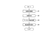
- the functions of the image processing unit 8, the marking extraction unit 9, and the display device 10 will be described in detail in the following description of the marking detection method using the marking detection device 1 for the round steel material S.
- each of the line sensor cameras constituting the plurality of image pickup devices 3 arranged along the axial direction of the round steel material S rotates the turning steel 2 in the circumferential direction.
- the uppermost position (specific position) P of the surface of S in the circumferential direction is imaged at a predetermined cycle with a resolution smaller than the dimension of the marking M to be measured (imaging step). That is, each imaging device 3 images the position of the uppermost position P on the surface of the round steel material S that rotates in the circumferential direction for one round of the round steel material S at a predetermined cycle with the above-described resolution.
- the size of the marking M is a circle having a diameter of about 4 mm
- the resolution of the line sensor camera that is, the width R in the circumferential direction of each pixel n (see FIG. 3) of one line is the maximum diameter circle.
- the width R ( ⁇ max) in the circumferential direction of each pixel n when imaging the steel material S1 is 630 ⁇ m/pix
- the width R ( ⁇ min) in the circumferential direction of each pixel n when imaging the round steel material S2 having the minimum diameter is 889 ⁇ m/ It is pix.
- the cycle of imaging with the line sensor camera is 1/2381 s so that the rotation speed of the round steel material S is 1500 mm/s, and the circumferential front surface of the round steel material S can be imaged without gaps. Has become.
- step S2 the image processing unit 8 of the computer system 7 obtains an image obtained by joining the images at the uppermost position (specific position) P captured by the line sensor cameras constituting each image capturing apparatus 3 in the circumferential direction.
- Process image processing step.
- the image processing unit 8 firstly outputs the original image (images of the plurality of uppermost positions P) from the line sensor cameras constituting each image pickup apparatus 3. ) Is taken in.
- step S22 the image processing unit 8 joins the captured original images (images at the plurality of uppermost positions P) in the circumferential direction of the round steel material S.
- An example of an image obtained by joining the original images in the circumferential direction of the round steel materials S is shown in the upper part of FIG. 7. Since it is difficult to detect the marking M in an image obtained by joining the original images in the circumferential direction of the round steel materials S, the binarization processing is performed later.
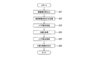
- step S23 the image processing unit 8 performs noise removal processing other than marking on the joined original images.
- step S24 the image processing unit 8 performs binarization processing on the stitched original image from which noise has been removed. Further, in step S25, the image processing unit 8 performs noise removal processing other than marking on the binarized image.
- An example of the image after noise removal is shown in the middle part of FIG. 7.
- step S26 the binarized image from which noise has been removed is output to the marking extraction unit 9.
- step S3 the marking extraction unit 9 of the computer system 7 extracts the marking M from the image subjected to the image processing in the image processing step (marking extraction step).
- marking extraction step will be described in detail.
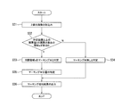
- the marking extraction unit 9 fetches the binarized image from the image processing unit 8 in step S31.
- step S32 it is determined whether or not there is a region a (see FIG. 8) of a set of pixels n1 (see FIG. 8) having a pixel value of 0 (white) having a predetermined area or more in the captured binary image.
- a pixel having a pixel value of 1 (black) is indicated by n2.
- the marking shape is circular and the diameter of the circular shape is D
- the number of pixels n1 that are equal to or greater than a value D/R obtained by dividing the diameter D by the width R ( ⁇ D) of each pixel are consecutive. It is determined whether or not there is an area a of the set that exists.
- the marking diameter is 4 mm
- the presence or absence of marking can be determined by determining whether or not there is marking.
- step S33 the marking extraction unit 9 determines that the area a is the marking M
- step S35 the marking extraction unit 9 determines the circumferential position x and the longitudinal position y of the marking M (see the lower row in FIG. 7). Identify.
- the marking extraction unit 9 determines that the area a is the marking M, as shown in the lower part of FIG. 7, the marking extraction unit 9 puts a mark 18 around the marking M to indicate the location of the marking M.
- the circumferential position x of the marking M means the circumferential length of the round steel material S from the imaging start point to the marking M in the circumferential direction.
- the marking extraction unit 9 receives the rotation speed of the turning roller 2 from the pulse generator 17, and the marking extraction unit 9 receives the rotation speed of the turning roller 2 and the diameter of the turning roller 2 which have been input.
- the circumferential length of the steel material S from the imaging start point to the marking M in the circumferential direction is calculated, and the circumferential position x of the marking M is specified.
- the longitudinal position y of the marking M means the axial length from the end surface of the round steel S in the axial direction to the marking M.
- the marking extraction unit 9 determines the number of pixels n from the end surface in the axial direction of the round steel material S to the marking M and the axial width R of each pixel n from the end surface in the axial direction of the round steel material S to the marking M.
- the length in the axial direction is calculated, and the longitudinal position y of the marking M is specified.
- the marking extraction unit 9 outputs the marking extraction result to the display device 10 in step S36.
- An example of the marking extraction result is shown in the lower part of FIG. 7, and the marking M, the mark 18 indicating the location of the marking M, and the circumferential position x and the longitudinal position y of the marking M are extracted.
- the circumferential position of the specific marking M is shown as x1 and the longitudinal position thereof is shown as y1.
- step S4 the display device 10 causes the marking extraction result output from the marking extraction unit 9 of the computer system 7, that is, the marking M, the marking 18 indicating the location of the marking M, and the circumferential direction of the marking M.
- the position x and the longitudinal position y are displayed.
- the operator who grinds the surface flaw of the round steel material S may grind the spot on the surface of the marked round steel material S based on the marking extraction result displayed on the display device 10. Further, the marking detection result extracted by the marking extraction unit 9 may be transferred to a surface flaw grinding device provided in a later process, and the marking portion may be automatically ground by the surface flaw grinding device.
- the round steel material S after grinding the marking points on the surface is sent to a further post-process (processes after the surface flaw grinding) and processed there to be a steel product which is a product.
- the further post-process is the whole of the subsequent process steps in which a round steel material having a defective portion whose surface is ground is processed.
- the round steel material S is a bar steel product such as a round bar steel or a product steel pipe, it is a refining process, a shipping process or the like performed after defect grinding.
- the round steel S is a material for rolling, it is a rolling process, a refining process performed thereafter, a shipping process, or the like.
- the steel material After the surface of the marked portion of the round steel material S, which has been marked on the surface with flaws (defects) by the above-mentioned marking detection method, is subjected to surface grinding, the steel material is sent to the subsequent step to visually detect the marking. Marking can be detected more efficiently and more accurately than in the case of. Therefore, the manufacturing efficiency of the steel material is improved. Further, since the marking detection accuracy is improved, the occurrence of obstacles in the subsequent process is suppressed.
- the obstacle in the post-process means that when the round steel is the material for rolling, the steel material after the rolling step in the post-process has a flaw caused by the surface defect in the material for rolling.
- the steel material is broken or the steel material is broken during the rolling process due to the surface defect in the material for rolling. Further, when the round steel material S is a bar steel product or a product steel pipe, it means that a product whose defective portion is not completely removed by grinding is shipped in the subsequent shipping process.
- the steel material from the step of applying the marking to the step of grinding the marking is a round steel material, that is, if it is a steel material with a circular cross section
- the steel material after the treatment in the post process does not necessarily have to be a round steel material.
- the steel material after the treatment in the process may be a steel material having a square cross section.
- the marking detection method according to the present invention is applied to either the marking detection of the raw material or the marking detection of the steel bar product. Can also be applied.
- the detection method of the present invention is used only for the marking detection of the material.
- the detection method of the present invention may be used only for detecting the marking of a product, or the marking detection method of the present invention may be used for both the detection of material marking and the detection of product marking.
- the uppermost position (specific position) in the circumferential direction of the surface of the round steel S that rotates in the circumferential direction is imaged in a predetermined cycle with a resolution smaller than the dimension of the marking M to be measured (imaging device 3, step S1 (imaging step)). Then, the image obtained by connecting the captured images of the above-mentioned uppermost position (specific position) P in the circumferential direction is processed (image processing unit 8, step S2 (image processing step)). Further, the marking M is extracted from the image processed image (marking extraction unit 9, step S3 (marking extraction step)).
- the marking detection device 1 and the detection method for the round steel material in which the risk of missing the marking M is significantly reduced by automatically detecting the marking M.
- the image pickup device 3 is a line sensor camera, it is possible to appropriately detect the shape of the marking M applied to the surface of the round steel material S which is an image pickup target.
- the pulse generator 17 for detecting the rotation speed of the turning roller 2 as a rotation angle detection device for detecting the rotation angle of the round steel material S is provided, the round steel material is calculated from the rotation speed of the turning roller 2 and the diameter of the turning roller.
- a circumferential position x of the marking M can be specified by calculating the circumferential length from the image pickup start point in the circumferential direction of S to the marking M.
- the size of the marking M is a circle having a diameter of about 4 mm
- the resolution of the line sensor camera that constitutes the imaging device 3 is 630 ⁇ m/pix and the minimum diameter when the round steel material S1 having the largest diameter is imaged.
- 889 ⁇ m/pix is set when the round steel material S2 is imaged
- the size of the marking M may be other than 4 mm in diameter.
- the resolution of the line sensor camera constituting the imaging device 3 may be any size as long as it is smaller than the size of the marking M.
- the line sensor camera constituting the image pickup device 3 images the specific position (uppermost position P) on the surface of the round steel material S rotating in the circumferential direction for one round of the round steel material S at a predetermined cycle. It is not limited to one round, and a plurality of rounds may be picked up.
- the imaging cycle of the line sensor camera which constitutes the imaging device 3 is not limited to 1/2381 s as long as it can image the surface of the round steel S in the circumferential direction without gaps.
- the size of the round steel material S to which the marking is applied is ⁇ 450 mm in maximum diameter and ⁇ 80 mm in minimum diameter, but can be arbitrarily changed.
- the color of the marking applied to the position of the surface flaw of the round steel material S by the marking device is different from the color of the illumination by the illumination device 5 (a color approximate to white), but it may be the same color.
- the color of the marking applied to the surface flaw position of the round steel material S by the marking device is described as a single color, but it may be a color.
- MLFT leakage flux flaw detection
- AUT ultrasonic flaw detection
- EC peeling flaw detection
- magner Magnetic particle flaw detection
- the marking device may perform marking of different colors for each flaw detection method.
- a color camera may be selected as the imaging device 3, and image processing, marking extraction, and marking extraction result display may be performed for each color.
- the line sensor camera is used as the imaging device 3
- an area sensor camera may be used.
- a range in which an angle ⁇ (acute angle side) formed between the line connecting the imaging device 3 and the position P on the surface of the round steel S to be imaged and the surface of the round steel S at the position P on the surface is 30 degrees or more.
- ⁇ is 30 degrees or more, it is easy to distinguish the marking from the noise, and the marking detection accuracy is improved.
- the number of the image pickup device 3 may be one as long as the single image pickup device 3 can pick up an image of the entire surface of the round steel S.
Landscapes
- Engineering & Computer Science (AREA)
- Mechanical Engineering (AREA)
- Physics & Mathematics (AREA)
- Optics & Photonics (AREA)
- General Physics & Mathematics (AREA)
- Investigating Materials By The Use Of Optical Means Adapted For Particular Applications (AREA)
- Constituent Portions Of Griding Lathes, Driving, Sensing And Control (AREA)
- Finish Polishing, Edge Sharpening, And Grinding By Specific Grinding Devices (AREA)
- Length Measuring Devices By Optical Means (AREA)
- Investigating Or Analyzing Materials By The Use Of Magnetic Means (AREA)
Abstract
Description
特許文献1に示す丸鋼材の表面疵手入れ装置は、回転している丸鋼材の軸線方向に沿い往復移動自在で、丸鋼材と接触して表面疵を検出する表面疵検査装置と、検出された表面疵の位置にマーキング液を噴射して印を付けるマーキング装置と、マーキングされた表面疵を手入れする作業デッキとを備えている。
この特許文献1に示す丸鋼材の表面疵手入れ装置によれば、検出された表面疵の位置をマーキングするようにしたので、作業者の研削位置判断を正確にし、研削作業を迅速に行うことができる。
即ち、特許文献1に示す丸鋼材の表面疵手入れ装置の場合、検出された表面疵の位置に塗布されたマーキングを作業者が目視により見つけ、その箇所を研削するようにしている。
ここで、丸鋼材の表面疵の位置に塗布されるマーキングは、マーキング液の吹付け具合によりその大きさや形が変わることがあり、作業者が目視で見つけにくい場合がある。従って、作業者の目視によってマーキングを見つける方法では、マーキングを見逃すリスクが大きく、研削能率が低いという問題があった。さらに、この問題は、マーキングを作業者の目視によって見つける方法を、一連の鋼材の製造プロセスの中の一工程として組み込んでいる鋼材の製造方法においては、製造能率が低いという問題に繋がっていた。
マーキング検出装置1において、図1及び図2に示すように、台座部11上に立設された複数の支持脚12に複数の第1支持部材13が支持脚12に対して直交するように取り付けられている。そして、これら第1支持部材13には、第2支持部材14が第1支持部材13に直交するように取り付けられている。また、複数の支持脚12の第1支持部材13を取り付けた部分より上方の位置には、複数の第3支持部材15が支持脚12に直交するように取り付けられている。また、これら第3支持部材15には、第4支持部材16が第3支持部材15に直交するように取り付けられている。
そして、各撮像装置3は、ラインセンサカメラで構成され、図2に示すようにラインセンサカメラの撮像ラインが延びる方向と丸鋼材Sの軸方向とが一致し、且つ図1に示すようにラインセンサカメラの光軸L3と丸鋼材Sの最上位置Pに接する接線TLとの成す角度δが90度となるように設置される。この光軸L3と接線TLとのなす角度δは90度に限ることなく、鋭角側が30度以上の範囲であれば好適である。
各撮像装置3を構成するラインセンサカメラの選定に際しては、被写界深度を計算し、被写体である最大径の丸鋼材S1の表面の最上位置P1と最小径の丸鋼材S2の表面の最上位置P2の場合でもピントが合うレンズを有するカメラを選定する。本実施形態の場合、被写界深度を771mmとし、最大径の丸鋼材S1の径がΦ450mm、最小径の丸鋼材S2の径がΦ80mmのいずれ場合でもピントが合うレンズを選定している。
各撮像装置3は、図示しない電源及び撮像周期等を制御するカメラ制御装置4に接続されている。
各照明装置5は、前述した第2支持部材14の先端に回転可能に取り付けられている。
この各照明装置5は、丸鋼材Sの表面、特に撮像される最上位置Pの近傍を連続的に点灯する2列のバー照明で構成されている。照明の色は白色に近似した色である。そして、図1に示すように、照明装置5の光軸L5と垂直線VLとのなす角度θは、最小径の丸鋼材S2の最上位置P2の近傍から最大径の丸鋼材S1の最上位置P1の近傍に至るまですべての場合に照射できるように、調節可能となっている。照明装置5は、最大径の丸鋼材S1の全長及び最小径の丸鋼材S2の全長を照明できるように、丸鋼材Sの軸方向に沿って複数設置されている。各照明装置5には、図示しない照明電源及び照明の輝度等を制御する照明制御装置6に接続されている。
このコンピュータシステム7は、画像処理部8及びマーキング抽出部9の各機能をコンピュータソフトウェア上でプログラムを実行することで実現するための演算処理機能を有するコンピュータシステムである。そして、このコンピュータシステムは、ROM,RAM,CPU等を備えて構成され、ROM等に予め記憶された各種専用のプログラムを実行することにより、前述した各機能をソフトウェア上で実現する。
画像処理部8、マーキング抽出部9及び表示装置10の各機能は、次の丸鋼材Sのマーキング検出装置1を用いたマーキング検出方法の説明にて詳細に説明する。
先ず、図4に示すステップS1で、丸鋼材Sの軸方向に沿って配置された複数個の撮像装置3を構成するラインセンサカメラの各々が、ターニングローラ2上を周方向に回転する丸鋼材Sの表面の周方向の最上位置(特定位置)Pを測定対象であるマーキングMの寸法よりも小さい分解能で所定周期で撮像する(撮像ステップ)。つまり、各撮像装置3が、周方向に回転する丸鋼材Sの表面の最上位置Pの位置を前述の分解能で所定周期で丸鋼材Sの一周分撮像する。本実施形態の場合、マーキングMの寸法は、直径約4mmの円形であり、ラインセンサカメラの分解能、即ち1ラインの各画素n(図3参照)の周方向の幅Rは、最大径の丸鋼材S1を撮像するときの各画素nの周方向の幅R(Φmax)で630μm/pix、最小径の丸鋼材S2を撮像するときの各画素nの周方向の幅R(Φmin)で889μm/pixとなっている。また、ラインセンサカメラで撮像する周期は、本実施形態の場合、丸鋼材Sの回転速度が1500mm/sであり、丸鋼材Sの周方向の前面を隙間なく撮像できるように、1/2381sとなっている。
この画像処理ステップについて詳しく述べると、図5に示すように、ステップS21において、画像処理部8は、先ず、各撮像装置3を構成するラインセンサカメラからの原画像(複数の最上位置Pの画像)を取り込む。
次いで、ステップS22において、画像処理部8は、取りこんだ原画像(複数の最上位置Pの画像)を丸鋼材Sの周方向に繋ぎ合わせる。原画像を丸鋼材Sの周方向に繋ぎ合わせた後の画像の一例が、図7の上段に示されている。原画像を丸鋼材Sの周方向に繋ぎ合わせた画像ではマーキングMが検出しづらいため、後に2値化処理を行う。
次いで、ステップS24において、画像処理部8は、ノイズを除去した繋ぎ合わせ原画像に2値化処理を行う。
更に、ステップS25において、画像処理部8は、2値化処理後の画像に対しマーキング以外のノイズ除去処理を行う。ノイズ除去後の画像の一例が、図7の中段に示されている。
そして、画像処理ステップの後、ステップS3において、コンピュータシステム7のマーキング抽出部9が、画像処理ステップで画像処理された画像からマーキングMを抽出する(マーキング抽出ステップ)。
このマーキング抽出ステップについて詳しく述べると、図6に示すように、先ず、マーキング抽出部9は、ステップS31において、画像処理部8から2値化画像を取り込む。
ステップS33では、マーキング抽出部9は、当該領域aをマーキングMと判定し、ステップS35で、マーキング抽出部9は、マーキングMの周方向位置x及び長手方向位置y(図7における下段参照)を特定する。
ここで、マーキング抽出部9は、当該領域aをマーキングMと判定した際に、図7における下段に示すように、マーキングMの周囲に、マーキングMの箇所を指摘する印18を付ける。
図7における下段には、マーキング抽出結果の一例が示されており、マーキングM、当該マーキングMの箇所を指摘する印18、及びマーキングMの周方向位置x及び長手方向位置yが抽出される。図7における下段には、特定のマーキングMの周方向位置がx1、長手方向位置がy1で示されている。
最後に、ステップS4において、表示装置10は、コンピュータシステム7のマーキング抽出部9から出力されたマーキング抽出結果、即ち、マーキングM、当該マーキングMの箇所を指摘する印18、及びマーキングMの周方向位置x及び長手方向位置yを表示する。
また、マーキング抽出部9で抽出されたマーキング検出結果を、後工程に設けられる表面疵研削装置に転送し、表面疵研削装置にて自動でマーキング箇所を研削するようにしてもよい。
表面のマーキング箇所を研削した後の丸鋼材Sは、さらなる後工程(表面疵研削以降の工程)へ送られて、そこで処理されて製品である鋼材とされる。
ここで、さらなる後工程とは、欠陥部が表面研削された丸鋼材を処理対象とした、その後の処理工程の全般のことである。すなわち、丸鋼材Sが丸棒鋼のような条鋼製品や製品鋼管である場合には、欠陥研削後に行われる精整工程、出荷工程等である。丸鋼材Sが圧延用素材である場合には、圧延工程やその後に行われる精整工程、出荷工程等である。
なお、丸ビレットのような丸鋼材を素材として、丸棒鋼のような条鋼製品を製造する場合において、本発明に係るマーキングの検出方法は、素材についてのマーキング検出、条鋼製品のマーキング検出のいずれにも適用できる。つまり、鋼材の製造方法に、本発明に係るマーキング検出方法を適用する場合は、素材、製品のいずれもが丸棒鋼である場合は、素材についてのマーキング検出にのみ、本発明の検出方法を用いてもよいし、製品についてのマーキング検出についてのみ本発明の検出方法を用いてもよいし、素材のマーキング検出と製品のマーキング検出との両方に本発明のマーキング検出方法を用いてもよい。
また、撮像装置3は、ラインセンサカメラであるので、撮像対象である丸鋼材Sの表面に塗布されたマーキングMの形状を適切に検出することができる。
また、丸鋼材Sの回転角度を検出する回転角度検出装置としてのターニングローラ2の回転数を検出するパルスジェネレータ17を備えているので、ターニングローラ2の回転数とターニングローラの直径とから丸鋼材Sの周方向における撮像開始点から当該マーキングMまでの周方向の長さを算出し、マーキングMの周方向位置xを特定することができる。
例えば、本実施形態において、マーキングMの寸法は直径約4mmの円形としてあり、撮像装置3を構成するラインセンサカメラの分解能は、最大径の丸鋼材S1を撮像するときで630μm/pix、最小径の丸鋼材S2を撮像するときで889μm/pixとしてあるが、マーキングMの寸法は直径4mm以外でもよい。また、撮像装置3を構成するラインセンサカメラの分解能は、マーキングMの寸法よりも小さければ、いかなる大きさであってもよい。
また、撮像装置3を構成するラインセンサカメラの撮像周期は、丸鋼材Sの周方向の表面を隙間なく撮像できる周期であれば1/2381sに限らない。
また、マーキングが塗布される丸鋼材Sの大きさは、最大径でΦ450mm、最小径でΦ80mmとしてあるが、任意に変更することができる。
また、マーキング装置で丸鋼材Sの表面疵の位置に塗布するマーキングの色は、照明装置5による照明の色(白色に近似した色)と異なる色としてあるが、同一色であってもよい。
また、撮像装置3は複数設置されているが、単一の撮像装置3で丸鋼材Sの全長の表面を撮像できるものであれば1台であってもよい。
2 ターニングローラ
3 撮像装置
4 カメラ制御装置
5 照明装置
6 照明制御装置
7 コンピュータシステム
8 画像処理部
9 マーキング抽出部
10 表示装置
11 台座部
12 支持脚
13 第1支持部材
14 第2支持部材
15 第3支持部材
16 第4支持部材
17 パルスジェネレータ(回転角度検出装置)
P 最上位置(特定位置)
S 丸鋼材
Claims (5)
- 丸鋼材の表面疵の位置に塗布されたマーキングを検出する丸鋼材のマーキング検出装置であって、
周方向に回転する前記丸鋼材の表面の周方向の特定位置を測定対象であるマーキングの寸法よりも小さい分解能で所定周期で撮像する撮像装置と、該撮像装置で撮像された前記特定位置の画像を周方向に繋ぎ合せて得られた画像を処理する画像処理部と、該画像処理部で画像処理された画像からマーキングを抽出するマーキング抽出部とを備えていることを特徴とする丸鋼材のマーキング検出装置。 - 前記撮像装置が、ラインセンサカメラであることを特徴とする請求項1に記載の丸鋼材のマーキング検出装置。
- 前記丸鋼材の回転角度を検出する回転角度検出装置を備えていることを特徴とする請求項1又は2に記載の丸鋼材のマーキング検出装置。
- 丸鋼材の表面疵の位置に塗布されたマーキングを検出する丸鋼材のマーキング検出方法であって、
周方向に回転する前記丸鋼材の表面の周方向の特定位置を測定対象であるマーキングの寸法よりも小さい分解能で所定周期で撮像する撮像ステップと、該撮像ステップで撮像された前記特定位置の画像を周方向に繋ぎ合せて得られた画像を処理する画像処理ステップと、該画像処理ステップで画像処理された画像からマーキングを抽出するマーキング抽出ステップとを含むことを特徴とする丸鋼材のマーキング検出方法。 - 丸鋼材の欠陥部を探傷し、探傷により発見した所定深さ以上の欠陥部がある箇所にマーキングを塗布し、その後に塗布されたマーキングを検出し、検出されたマーキングの部分を表面研削した後に、後工程で処理を行う鋼材の製造方法であって、
前記マーキングの検出は、請求項4に記載の丸鋼材のマーキング検出方法により行うことを特徴とする、鋼材の製造方法。
Priority Applications (2)
| Application Number | Priority Date | Filing Date | Title |
|---|---|---|---|
| CN201980078830.7A CN113165040B (zh) | 2018-11-29 | 2019-11-29 | 圆钢的标记检测装置和检测方法以及钢材的制造方法 |
| JP2020557863A JP7081687B2 (ja) | 2018-11-29 | 2019-11-29 | 丸鋼材のマーキング検出装置及び検出方法及び鋼材の製造方法 |
Applications Claiming Priority (4)
| Application Number | Priority Date | Filing Date | Title |
|---|---|---|---|
| JP2018-224181 | 2018-11-29 | ||
| JP2018224182 | 2018-11-29 | ||
| JP2018-224182 | 2018-11-29 | ||
| JP2018224181 | 2018-11-29 |
Publications (1)
| Publication Number | Publication Date |
|---|---|
| WO2020111247A1 true WO2020111247A1 (ja) | 2020-06-04 |
Family
ID=70853023
Family Applications (2)
| Application Number | Title | Priority Date | Filing Date |
|---|---|---|---|
| PCT/JP2019/046840 Ceased WO2020111246A1 (ja) | 2018-11-29 | 2019-11-29 | 丸鋼材の欠陥研削方法および鋼材の製造方法 |
| PCT/JP2019/046841 Ceased WO2020111247A1 (ja) | 2018-11-29 | 2019-11-29 | 丸鋼材のマーキング検出装置及び検出方法及び鋼材の製造方法 |
Family Applications Before (1)
| Application Number | Title | Priority Date | Filing Date |
|---|---|---|---|
| PCT/JP2019/046840 Ceased WO2020111246A1 (ja) | 2018-11-29 | 2019-11-29 | 丸鋼材の欠陥研削方法および鋼材の製造方法 |
Country Status (3)
| Country | Link |
|---|---|
| JP (2) | JP6897889B2 (ja) |
| CN (2) | CN113165041B (ja) |
| WO (2) | WO2020111246A1 (ja) |
Cited By (2)
| Publication number | Priority date | Publication date | Assignee | Title |
|---|---|---|---|---|
| JP2021139630A (ja) * | 2020-03-02 | 2021-09-16 | 日本製鉄株式会社 | 表面検査装置及び表面検査方法 |
| JP2022063136A (ja) * | 2020-10-09 | 2022-04-21 | Jfeスチール株式会社 | 鋼材の撮像画像重ね合わせ方法及び鋼材のマーキング検出方法 |
Families Citing this family (4)
| Publication number | Priority date | Publication date | Assignee | Title |
|---|---|---|---|---|
| CN116577356B (zh) * | 2023-03-21 | 2025-09-19 | 中国航发北京航空材料研究院 | 一种用于射线检测的缺陷深度定位方法及检测装置 |
| CN118543709B (zh) * | 2024-07-29 | 2024-10-18 | 江苏月仙科技股份有限公司 | 一种铝型材矫直机及铝型材矫直工艺 |
| CN118730908B (zh) * | 2024-09-02 | 2025-02-14 | 河南乾钧沛德工程管理有限公司 | 用于架空电力线路的巡检装置及其巡检方法 |
| CN120318233B (zh) * | 2025-06-17 | 2025-09-02 | 武汉科美达智能新技术有限公司 | 一种基于3d点云技术的钢坯表面视觉检测方法及系统 |
Citations (5)
| Publication number | Priority date | Publication date | Assignee | Title |
|---|---|---|---|---|
| JPS5415590A (en) * | 1977-07-06 | 1979-02-05 | Kawasaki Steel Corp | Metho of and apparatus for cutting surface defect of rod-shaped material |
| JPH07237106A (ja) * | 1994-02-28 | 1995-09-12 | Nippon Steel Corp | 遠隔操作疵手入れ方法およびその装置 |
| JP2002039948A (ja) * | 2000-07-27 | 2002-02-06 | Sony Corp | 外観検査装置及び外観検査方法 |
| KR20050063459A (ko) * | 2003-12-22 | 2005-06-28 | 재단법인 포항산업과학연구원 | 영상처리방법을 이용한 온라인 봉강재 표면시험검사장치 |
| JP2017146302A (ja) * | 2016-02-12 | 2017-08-24 | Jfeスチール株式会社 | 表面欠陥検査装置および表面欠陥検査方法 |
Family Cites Families (21)
| Publication number | Priority date | Publication date | Assignee | Title |
|---|---|---|---|---|
| JPH0626786B2 (ja) * | 1986-04-30 | 1994-04-13 | 三島光産株式会社 | 円柱外面疵の研削方法と装置 |
| JP3156140B2 (ja) * | 1992-03-12 | 2001-04-16 | 株式会社日立製作所 | 金属部材の損傷検査方法および損傷検査装置 |
| JP2820632B2 (ja) * | 1994-12-21 | 1998-11-05 | 株式会社ノリタケカンパニーリミテド | 自動疵取り装置 |
| KR100400184B1 (ko) * | 1997-10-31 | 2003-10-01 | 제이에프이 스틸 가부시키가이샤 | 원기둥체 표면의 초음파 탐상방법과 그 탐상장치및 이를 이용한 롤의 연삭방법 |
| JP3663050B2 (ja) * | 1998-05-19 | 2005-06-22 | 山陽特殊製鋼株式会社 | 長尺材料の自動疵取り方法及び自動疵取り装置 |
| JP2000117612A (ja) * | 1998-10-16 | 2000-04-25 | Sumitomo Metal Ind Ltd | 被研削材の疵手入れ方法及び装置 |
| JP2000141198A (ja) * | 1998-11-05 | 2000-05-23 | Kawasaki Steel Corp | 丸棒材の欠陥自動研削方法及び装置 |
| DE10154036A1 (de) * | 2001-11-02 | 2003-05-15 | Koenig & Bauer Ag | Einrichtung zum Erfassen der Position einer Seitenkante |
| US6909988B2 (en) * | 2002-10-15 | 2005-06-21 | General Electric Company | Method for positioning defects in metal billets |
| ES2222839B1 (es) * | 2004-01-23 | 2005-10-01 | Recobriments Industrials De Tecnologia Avancada, S.L. | Procedimiento para la fabricacion de barras de acero calibradas libres de defectos e instalacion para su fabricacion. |
| JP4509833B2 (ja) * | 2005-03-18 | 2010-07-21 | 株式会社神戸製鋼所 | アルミニウム合金棒材の表面欠陥検査方法 |
| CN102652960B (zh) * | 2011-03-02 | 2015-09-30 | 宁波宝新不锈钢有限公司 | 轧机支撑辊轴承表面缺陷的处理方法 |
| MX340378B (es) * | 2012-07-04 | 2016-07-07 | Nippon Steel & Sumitomo Metal Corp | Dispositivo de deteccion de defectos, metodo de deteccion de defectos, programa y medio de almacenamiento. |
| CN102878955B (zh) * | 2012-10-09 | 2015-05-20 | 中天科技精密材料有限公司 | 一种大直径预制棒偏心率的测量设备及其测量方法 |
| CN104422693B (zh) * | 2013-08-23 | 2018-12-14 | 上海金艺检测技术有限公司 | 冷轧辊表面微小线性缺陷的定性检测方法 |
| CN104076042B (zh) * | 2014-07-18 | 2016-08-24 | 株洲硬质合金集团有限公司 | 圆柱形棒材外观自动检测装置 |
| CN105424722A (zh) * | 2015-11-05 | 2016-03-23 | 天津大学 | 一种基于机器视觉的瓶盖不合格品标记方法 |
| CN105333828B (zh) * | 2015-11-19 | 2016-11-30 | 西安交通大学 | 一种四轴联动跟踪式曲轴测量方法 |
| JP6493340B2 (ja) * | 2016-08-31 | 2019-04-03 | Jfeスチール株式会社 | 鋼管疵手入れガイダンスシステム |
| CN106645181A (zh) * | 2017-02-24 | 2017-05-10 | 清华大学 | 基于显微视觉的轧辊磨削表面缺陷检测系统 |
| CN107576664A (zh) * | 2017-09-28 | 2018-01-12 | 清华大学 | 一种轧辊磨削表面缺陷机器视觉检测系统 |
-
2019
- 2019-11-29 WO PCT/JP2019/046840 patent/WO2020111246A1/ja not_active Ceased
- 2019-11-29 JP JP2020557862A patent/JP6897889B2/ja active Active
- 2019-11-29 WO PCT/JP2019/046841 patent/WO2020111247A1/ja not_active Ceased
- 2019-11-29 JP JP2020557863A patent/JP7081687B2/ja active Active
- 2019-11-29 CN CN201980078989.9A patent/CN113165041B/zh active Active
- 2019-11-29 CN CN201980078830.7A patent/CN113165040B/zh active Active
Patent Citations (5)
| Publication number | Priority date | Publication date | Assignee | Title |
|---|---|---|---|---|
| JPS5415590A (en) * | 1977-07-06 | 1979-02-05 | Kawasaki Steel Corp | Metho of and apparatus for cutting surface defect of rod-shaped material |
| JPH07237106A (ja) * | 1994-02-28 | 1995-09-12 | Nippon Steel Corp | 遠隔操作疵手入れ方法およびその装置 |
| JP2002039948A (ja) * | 2000-07-27 | 2002-02-06 | Sony Corp | 外観検査装置及び外観検査方法 |
| KR20050063459A (ko) * | 2003-12-22 | 2005-06-28 | 재단법인 포항산업과학연구원 | 영상처리방법을 이용한 온라인 봉강재 표면시험검사장치 |
| JP2017146302A (ja) * | 2016-02-12 | 2017-08-24 | Jfeスチール株式会社 | 表面欠陥検査装置および表面欠陥検査方法 |
Cited By (4)
| Publication number | Priority date | Publication date | Assignee | Title |
|---|---|---|---|---|
| JP2021139630A (ja) * | 2020-03-02 | 2021-09-16 | 日本製鉄株式会社 | 表面検査装置及び表面検査方法 |
| JP7360048B2 (ja) | 2020-03-02 | 2023-10-12 | 日本製鉄株式会社 | 表面検査装置及び表面検査方法 |
| JP2022063136A (ja) * | 2020-10-09 | 2022-04-21 | Jfeスチール株式会社 | 鋼材の撮像画像重ね合わせ方法及び鋼材のマーキング検出方法 |
| JP7351282B2 (ja) | 2020-10-09 | 2023-09-27 | Jfeスチール株式会社 | 鋼材の撮像画像重ね合わせ方法及び鋼材のマーキング検出方法 |
Also Published As
| Publication number | Publication date |
|---|---|
| CN113165040A (zh) | 2021-07-23 |
| CN113165040B (zh) | 2024-10-29 |
| CN113165041B (zh) | 2022-11-01 |
| JPWO2020111247A1 (ja) | 2021-10-14 |
| JP6897889B2 (ja) | 2021-07-07 |
| JPWO2020111246A1 (ja) | 2021-09-02 |
| WO2020111246A1 (ja) | 2020-06-04 |
| JP7081687B2 (ja) | 2022-06-07 |
| CN113165041A (zh) | 2021-07-23 |
Similar Documents
| Publication | Publication Date | Title |
|---|---|---|
| JP7081687B2 (ja) | 丸鋼材のマーキング検出装置及び検出方法及び鋼材の製造方法 | |
| JP5888035B2 (ja) | 円筒体又は円柱体材料の表面欠陥検査方法及び装置 | |
| JP6633454B2 (ja) | 変状部の検出方法 | |
| JP5954284B2 (ja) | 表面欠陥検査装置及び表面欠陥検査方法 | |
| JP3156764U (ja) | 表面疵検査装置 | |
| JPWO2011117984A1 (ja) | フィルタ検査方法および装置 | |
| EP3315951A1 (en) | Surface defect detection apparatus and surface defect detection method | |
| JP6360782B2 (ja) | ねじ類の検査方法 | |
| JP2010071722A (ja) | 凹凸疵検査方法及び装置 | |
| JP2017146302A (ja) | 表面欠陥検査装置および表面欠陥検査方法 | |
| JP6605772B1 (ja) | 欠陥検査装置および欠陥検査方法 | |
| JP6387909B2 (ja) | 表面欠陥検出方法、表面欠陥検出装置、及び鋼材の製造方法 | |
| JP2007230706A (ja) | ベルトコンベアの縦裂き検知方法および装置 | |
| JP7360048B2 (ja) | 表面検査装置及び表面検査方法 | |
| JP7351282B2 (ja) | 鋼材の撮像画像重ね合わせ方法及び鋼材のマーキング検出方法 | |
| JP3593544B2 (ja) | 金属表面の欠陥検出方法 | |
| JPH0694660A (ja) | 表面欠陥検査方法及び装置 | |
| JP2008309708A (ja) | 長尺物の外観検査方法及びその装置 | |
| JP6432448B2 (ja) | ガラス管の検査方法 | |
| JPH01157770A (ja) | 素材の表面欠陥除去方法 | |
| JP5994413B2 (ja) | リング状物品の欠肉の検査装置 | |
| JP2015059854A (ja) | 欠陥検査方法及び欠陥検査装置 | |
| JP2013185831A (ja) | 表面欠陥検査装置 | |
| JP6146389B2 (ja) | 鋼材表面検査装置及びその方法 | |
| JP2015025745A (ja) | 円筒形ワークの形状計測方法、及び円筒形ワークの形状計測装置 |
Legal Events
| Date | Code | Title | Description |
|---|---|---|---|
| 121 | Ep: the epo has been informed by wipo that ep was designated in this application |
Ref document number: 19890172 Country of ref document: EP Kind code of ref document: A1 |
|
| ENP | Entry into the national phase |
Ref document number: 2020557863 Country of ref document: JP Kind code of ref document: A |
|
| NENP | Non-entry into the national phase |
Ref country code: DE |
|
| 122 | Ep: pct application non-entry in european phase |
Ref document number: 19890172 Country of ref document: EP Kind code of ref document: A1 |
|
| WWG | Wipo information: grant in national office |
Ref document number: 202117028102 Country of ref document: IN |