WO2020110467A1 - コンパクト容器 - Google Patents
コンパクト容器 Download PDFInfo
- Publication number
- WO2020110467A1 WO2020110467A1 PCT/JP2019/039531 JP2019039531W WO2020110467A1 WO 2020110467 A1 WO2020110467 A1 WO 2020110467A1 JP 2019039531 W JP2019039531 W JP 2019039531W WO 2020110467 A1 WO2020110467 A1 WO 2020110467A1
- Authority
- WO
- WIPO (PCT)
- Prior art keywords
- lid
- saucer
- absorbing member
- shock absorbing
- peripheral wall
- Prior art date
- Legal status (The legal status is an assumption and is not a legal conclusion. Google has not performed a legal analysis and makes no representation as to the accuracy of the status listed.)
- Ceased
Links
Images


Classifications
-
- A—HUMAN NECESSITIES
- A45—HAND OR TRAVELLING ARTICLES
- A45D—HAIRDRESSING OR SHAVING EQUIPMENT; EQUIPMENT FOR COSMETICS OR COSMETIC TREATMENTS, e.g. FOR MANICURING OR PEDICURING
- A45D33/00—Containers or accessories specially adapted for handling powdery toiletry or cosmetic substances
Definitions
- the present invention relates to a compact container in which a shock absorbing member is arranged between a saucer member and a container body.
- the compact container is generally used as a cosmetic container, but the solid cosmetics fixed to the saucer member are easily collapsed so that they can be easily applied. Therefore, conventionally, there is known one in which a shock absorbing member is arranged between the tray member and the container body.
- a shock absorbing member is arranged between the tray member and the container body.
- a sheet-like seat portion having a hollow protrusion so as to form a space between the bottom surface of the recess of the container body and the bottom portion of the saucer member, and the saucer member standing upright from the seat portion
- a saucer storage section made of a flexible material having a peripheral wall for holding the side wall of the container, and an arm section extending upward from the peripheral wall of the saucer storage section to the outside and having the arm section fixed to the container body.
- an elastic member is used in addition to the shock absorbing member, such as an elastic member for flipping up the lid body when the engagement between the lid body and the container body is released. , was a factor that increased the number of parts.
- An object of the present invention is to provide a compact container capable of reducing the number of parts while maintaining the function of the compact container.
- the present invention has been made to solve the above problems, the compact container of the present invention, A saucer member for fixing a solid object, a container body in which a recess for accommodating the saucer member is formed, and a lid body capable of opening and closing the upper end opening of the recess, the saucer member and the container body
- a compact container in which a shock absorbing member is arranged The impact absorbing member has a peripheral wall that surrounds the saucer member from the outside in plan view, and a bottom wall that closes the lower end portion of the peripheral wall and covers the saucer member from below,
- the container body has an unlocking member capable of releasing the engagement between the lid body and the container body by pressing inward, At least a part of the shock absorbing member is formed of an elastic member, and when the lid is closed, the lid urging portion that abuts on the lid and urges the lid in the opening direction, or At least one of the unlocking member urging portions for pressing the unlocking member to the outside is integrally provided.
- the lid urging portion is provided so as to project from the upper end portion of the peripheral wall to a substantially horizontal outer side.
- the lid urging portion projects rearward from an upper end portion of the peripheral wall, By rotating the lid body around a rotation shaft located below the lid body urging portion, the lid body urging portion abuts against a vertical rib formed on a rear portion of the lid body from the front. It is preferable that the lid is biased in the opening direction.
- the unlocking member urging portion is provided so as to project forward from an upper end portion of the peripheral wall, and presses the unlocking member forward.
- the bottom wall of the impact absorbing member is configured by a reinforcing portion made of synthetic resin that reinforces the elastic member.
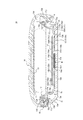
- FIG. 1B is a cross-sectional view taken along the line AA of FIG. 1A and is a right side cross-sectional view of the compact container according to the first embodiment of the present invention.
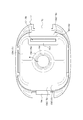
- It is a bottom view of an inside frame member and a shock absorption member in a compact container which is a 1st embodiment of the present invention.
- It is a right sectional view of the compact container which is 2nd Embodiment of this invention.
- the compact container 10 according to the present embodiment is particularly suitable as a compact cosmetic container for containing cosmetics and the like.
- the compact container 10 of the present embodiment includes a container body 13 that forms a space for containing a solid material such as cosmetics, and a lid 14 that covers an upper end opening of the container body 13. Further, the container body 13 is provided with a hook piece 18 that can release the lid body 14 by releasing the engagement between the lid body 14 and the container body 13 by pressing inward.
- the up-down direction is the up-down direction in FIG. 1A
- the left-right direction is the left-right direction in FIG. 1A.
- a direction perpendicular to the plane of the drawing and toward the front in FIG. is the direction from the center of the compact container 10 to the outside in FIG. 1B, and the inward direction in plan view is the direction from the outer edge of the compact container 10 to the center in FIG. 1B.
- FIG. 2 is a sectional view taken along the line AA of FIG. 1A and is a right side sectional view of the compact container 10 according to the present embodiment.
- the left side of FIG. 2 is the front and the right side is the rear.
- the recess 13d of the container body 13 is disposed between the saucer member 12 for containing the solid cosmetics S and the saucer member 12 and the container body 13, and the impact on the saucer member 12 is prevented.
- a shock absorbing member 15 for absorbing is arranged.
- the saucer member 12 is integrally provided with a side portion 12a having a substantially rectangular cross section and a bottom portion 12b closing a lower end of the side portion 12a, and a solid cosmetic S as a solid substance is fixedly held inside thereof.
- the bottom portion 12b is composed of a side edge portion 12b2 connected to the lower end of the side portion 12a, and a central bottom portion 12b1 that is connected to the inside of the side edge portion 12b2 via a step portion 12b3 and projects slightly upwardly in plan view. As shown in the figure, by configuring the central bottom portion 12b1 to project upward with respect to the peripheral portion 12b2, the bending rigidity is increased in the step portion 12b3, and the saucer member 12 can be made difficult to deform in the bending direction. ..
- the side portion 12a and the bottom portion 12b of the saucer member 12 are integrally formed of aluminum, and the solid cosmetic material S, which is a solid substance, is fixedly held inside thereof. Further, the bottom portion 12b of the tray member 12 is formed by adhering a stainless steel ferromagnetic member having substantially the same shape to the lower surface of the aluminum member by adhesion.
- the bottom portion 12b of the tray member 12 according to the present embodiment is composed of both the aluminum member and the ferromagnetic member.
- the bottom portion 12b of the saucer member 12 can be formed by bonding a ferromagnetic member such as a stainless steel plate to an aluminum member by adhesion or the like.
- a ferromagnetic member such as a stainless steel plate
- the present invention is not limited to this mode, and the bottom portion 12b of the tray member 12 may be formed by bonding a ferromagnetic material member to a member made of various synthetic resins by adhesion or the like.
- the ferromagnetic material include iron, martensite-based, ferrite-based, austenite-ferrite-based stainless steel, cobalt, nickel or their alloys (permalloy, etc.), ferrite, and the like.
- the ferromagnetic member is attached to the entire surface of the bottom portion 12b, but the present invention is not limited to this mode. At least a part of the bottom portion 12b may be covered with a ferromagnetic material so that the ferromagnetic material portion and a magnet member M described later at least partially overlap each other in plan view.
- the container body 13 is integrally provided with a bottom portion 13b at a lower end of a side portion 13a having a substantially rectangular cross section, and a recess 13d for accommodating the saucer member 12 and the impact absorbing member 15 is formed inside thereof. ..
- a through hole 13h that vertically penetrates the bottom portion 13b is provided near the rear of the container body 13. The user inserts a bar or the like through the through hole 13h and the through hole 15h provided in the bottom wall 15b of the shock absorbing member 15, and directly presses the bottom portion 12b of the saucer member 12 with the bar or the like to form a tray.
- the member 12 can be removed from the shock absorbing member 15 and replaced. That is, the solid cosmetics S can be refilled.
- the through hole 15h does not necessarily have to be provided.
- reference numeral 14 is a lid that can open and close the upper end opening of the recess 13d.
- the lid 14 is connected to the container body 13 via a cylindrical pin P located below a lid urging portion 15j extending rearward from an upper end of a peripheral wall 15a of a shock absorbing member 15, which will be described later. It can be rotated around P.
- the lid 14 is urged in the direction in which the lid 14 is opened by the lid urging portion 15j of the shock absorbing member 15 coming into contact with the longitudinal rib 14r formed on the rear portion of the lid 14 from the front. .. That is, in the closed state shown in FIG.
- the lid 14 is pressed rearward by the lid urging portion 15j located above the pin P that is the center of rotation, and as a result, the lid 14 rotates backward. Then, the rotational moment in the releasing direction is acting. Therefore, when the user presses the hook piece 18 (unlock member) described later inward (rearward), the engagement between the lid body 14 and the container body 13 is released, and the lid body 14 is rotated by the above-described rotation moment. It is opened by rotating slightly backward. Further, the lid 14 can be brought into the closed state shown in FIG. 2 by rotating the lid 14 forward around the pin P and engaging the hook 14f with the hook 13f provided on the container body 13. In this embodiment, the mirror 19 is fixed to the lower surface of the lid body 14.
- Numeral 15 is a shock absorbing member.
- the shock absorbing member 15 has a configuration including a flexible elastic material typified by an elastomer and rubber.
- the shock absorbing member 15 is integrally provided with a bottom wall 15b at a lower end of a peripheral wall 15a having a substantially rectangular cross section, and the tray member 12 is housed inside the bottom wall 15b. That is, the peripheral wall 15a surrounds the saucer member 12 from the outside in a plan view, and the bottom wall 15b covers the saucer member 12 from below.
- the peripheral wall 15a stands upright from the bottom wall 15b and surrounds and holds the side portion 12a of the saucer member 12 from the outside in plan view.
- the peripheral wall 15a is formed with an annular projection 15p that projects inwardly over the entire circumference of the inner peripheral surface thereof.
- the inner peripheral surface of the annular projection 15p and the outer peripheral surface of the side portion 12a of the tray member 12 are configured to be a tight fit. Therefore, by fitting the side portion 12a of the tray member 12 to the inner peripheral surface of the peripheral wall 15a of the shock absorbing member 15, the annular projection 15p is elastically deformed outward in plan view and is attached to the side portion 12a of the tray member 12. Abut and press inward.
- the tray member 12 is retained and retained by the shock absorbing member 15 (annular protrusion 15p) and elastically supported in the front-rear, left-right direction. Further, since the bottom portion 12b (edge portion 12b2) of the tray member 12 is close to the bottom wall 15b of the shock absorbing member 15, the tray member 12 can be elastically supported in the vertical direction. As a result, even if the container body 13 receives an impact from any of the front, rear, left, right, and top directions, the impact is not directly transmitted to the tray member 12, and the impact is absorbed by the impact absorbing member 15. Therefore, it is possible to prevent the solid cosmetic S contained in the saucer member 12 from being cracked or chipped.
- annular protrusion is also provided on the outer peripheral surface of the side portion 12a of the tray member 12, and the annular protrusion is locked to the annular protrusion 15p so that the tray member 12 can be removed from the impact absorbing member 15. May be firmly prevented.
- the annular projection 15p does not necessarily have to be provided over the entire circumference, and may be provided intermittently in the circumferential direction.
- a through hole 15h (see FIG. 2) that vertically penetrates the bottom wall 15b.
- the user inserts a rod or the like through the through hole 15h and the through hole 13h provided in the bottom portion 13b of the container body 13, and directly presses the bottom portion 12b of the tray member 12 with the rod member or the like. Can be removed from the shock absorbing member 15 and replaced. That is, the solid cosmetics S can be refilled.
- the through hole 15h does not necessarily have to be provided.
- the through hole 13h is provided in the bottom portion 13b of the container body 13 and the through hole 15h is not provided in the bottom wall 15b of the shock absorbing member 15, the user inserts a bar or the like through the through hole 13h,
- the impact absorbing member 15 may be elastically deformed by pressing the bottom wall 15b of the impact absorbing member 15, and the tray member 12 may be pressed from below via the impact absorbing member 15.
- the bottom wall 15b of the shock absorbing member 15 extends further inward from the inner edge of the side edge 15b2 and the step 15b5 from the inner edge of the side edge 15b2, which is continuous with the lower end of the peripheral wall 15a in right side view. It is provided with an intermediate bottom wall 15b3 and a central bottom wall 15b1 provided inside the intermediate bottom wall 15b3 via a reinforcing portion 15b4 (see FIG. 3).
- the reinforcing portion 15b4 can be formed of, for example, a synthetic resin such as acrylonitrile-butadiene-styrene (ABS) resin.
- ABS acrylonitrile-butadiene-styrene
- the edge portion 15b2, the intermediate bottom wall 15b3, and the central bottom wall 15b1 are formed of elastic members, and the reinforcing portion 15b4 is formed of synthetic resin such as ABS resin.
- the central bottom wall 15b1 (including the magnet member M) and the reinforcing portion 15b4 are formed thick with respect to the peripheral edge portion 15b2, so that the bending rigidity is increased in the central bottom wall 15b1 and the reinforcing portion 15b4. Therefore, the bending rigidity of the entire shock absorbing member 15 can be increased, and the member can be easily handled and transported.
- bending rigidity can be improved by using a synthetic resin such as ABS resin having a larger elastic coefficient than that of the elastic member. Therefore, it is possible to suppress bending of the shock absorbing member 15 as a whole, improve the handleability of the shock absorbing member 15, and facilitate the assembly of the compact container 10.
- the saucer member 12 since the edge portion 12b2 of the bottom portion 12b of the saucer member 12 is close to the edge portion 15b2 of the shock absorbing member 15, the saucer member 12 can be elastically supported in the vertical direction by the shock absorbing member 15. is there.
- the thickness of the corner portion 15c where the peripheral wall 15a and the bottom wall 15b of the shock absorbing member 15 intersect is made thinner than the average thickness of the bottom wall 15b.
- the peripheral edge portion 15b2, the corner portion 15c, and the peripheral wall 15a are thinner than the central bottom wall 15b1 and the reinforcing portion 15b4. Therefore, when a shock is applied to the container body 13, the edge portions 15b2, the corners 15c, and the peripheral wall 15a are deformed as a whole, so that the shock absorbing member 15 is deformed while following the movement of the container body 13. The shock applied to 13 can be effectively absorbed.
- a magnet member M is fixed to the lower surface of the bottom wall 15b as shown in FIG.
- the magnet member M is a plate-shaped member having a substantially rectangular shape in plan view, and is magnetized in the vertical direction of FIG.
- the magnet member M for example, a ferrite magnet or a neodymium magnet can be used.
- the magnet member M may be configured by combining the above-mentioned magnet material with another ferromagnetic material as a core material.
- the magnet member M is fitted and fixed in the recess 15e provided in the lower surface of the bottom wall 15b of the shock absorbing member 15.
- the recess 15e into which the magnet member M is fitted is defined by a fitting tubular portion 15d that surrounds the periphery, and the magnet member M is undercut with an engaging projection 15d1 formed at the lower end of the fitting tubular portion 15d. It is attached so that it cannot be detached when engaged.
- the magnet member M and the ferromagnetic material portion of the saucer member 12 overlap each other in a plan view. Therefore, the magnet member M and the ferromagnetic material portion of the saucer member 12 attract each other in the vertical direction. Therefore, as will be described later, even if the saucer member 12 moves upward in the container body 13 due to an impact, the saucer member is caused by the attractive force acting between the magnet member M and the ferromagnetic material portion. It is possible to return and maintain the state where 12 is fitted in the shock absorbing member 15.
- the above-described structure has a remarkable effect particularly when a shock is applied to the container body 13 or the like with the lid 14 opened.
- the shock absorbing member 15 and the middle frame member 17 are made of different materials by insert molding or two-color molding (double molding) (for example, the shock absorbing member 15 is an elastomer and the middle frame member 17 is an ABS resin). It is configured as one. Then, as shown in FIG. 2, the impact absorbing member 15 is fixed to the container body 13 by disposing the middle frame member 17 on the step portion 13e formed on the side portion 13a of the container body 13. Instead of fixing the shock absorbing member 15 to the container body 13 via the middle frame member 17, the shock absorbing member 15 may be directly fixed to the container body 13 by means of bonding or the like.
- a lid urging portion 15j is provided so as to project rearward from the upper end of the peripheral wall 15a via a flange portion 15f.
- the lid urging portion 15j is provided integrally with the shock absorbing member 15, and is in contact with the vertical rib 14r formed on the rear portion of the lid 14 in the closed state of the lid 14 shown in FIG. ..
- the shape of the lid urging portion 15j shown in FIG. 2 is an initial shape in which the lid urging portion 15j is not in contact with the vertical rib 14r. Then, when the lid 14 is closed, the vertical rib 14r pushes the lid urging portion 15j forward, and moves to the position shown in FIG. 2 while elastically deforming the lid urging portion 15j.
- the vertical rib 14r of the lid 14 is biased rearward by the lid biasing portion 15j. Then, when the hook piece 18 (unlock member) is pressed inward (rearward) to release the engagement between the lid body 14 and the container body 13, the lid body urging portion 15j applies a rotational moment to the lid body 14. Given, it rotates backward around the pin P. That is, the lid urging portion 15j can support the lid 14 from jumping up.
- FIG. 3 is a bottom view of the shock absorbing member 15 and the intermediate frame member 17 formed integrally with the shock absorbing member 15.
- the elastic member or the magnet member M is exposed on the lower surface at the central portion and the peripheral portion, and the other region is covered with the reinforcing portion 15b4.
- the elastic member is exposed to the upper surface at the central portion and the peripheral portion, and the other region is covered with the reinforcing portion 15b4.
- the tray member 12 is supported by the impact absorbing member 15 in a state of being separated from the side portion 13a and the bottom portion 13b of the container body 13. Therefore, the shock received by the container body 13 is transmitted to the saucer member 12 through the peripheral wall 15a and the bottom wall 15b of the shock absorbing member 15, so that the saucer member 12 does not receive the shock from the container body 13 directly.
- a new compact container 10 that does not cause cracks or chips in the solid cosmetics S housed in the saucer member 12 by effectively absorbing the shock transmitted to the saucer member 12 is provided. be able to.
- the lid 14 forms a space for accommodating a makeup tool T such as a puff inside thereof.
- a hook 13f that engages with a hook 14f provided on the lid 14 to prevent the lid 14 from opening is provided, and the hooks 14f and 13f are engaged with each other. It is possible to provide a hook piece 18 (unlock member) for releasing the hook by pushing it.
- the through hole 13h formed in the container body 13 introduces outside air between the container body 13 and the lid body 14, when the container body 13 and the lid body 14 are hermetically sealed, the negative pressure This is effective in preventing the functional deterioration of the shock absorbing member 15 caused by the above.
- the shock absorbing member 15 has a hook piece 18 (unlocking member) that can be released from engagement with the shock absorbing member 15, and at least a part of the shock absorbing member 15 is formed of an elastic member.
- a lid urging portion 15j that contacts and urges the lid 14 in the opening direction is integrally provided.
- the lid urging portion 15j is configured to be provided so as to project from the upper end portion of the peripheral wall 15a to the outer side in the substantially horizontal direction.
- the lid body urging portion 15j can be easily brought into contact with the rib or the like on the inner surface of the lid body 14 to urge the lid body 14.
- the lid urging portion 15j projects rearward from the upper end portion of the peripheral wall 15a, and the lid 14 rotates around the rotation axis (pin P) located below the lid urging portion 15j.
- the lid body urging portion 15j is configured to be urged in the opening direction when the lid body urging portion 15j comes into contact with the vertical rib 14r formed on the rear portion of the lid body 14 from the front.
- the bottom wall 15b of the shock absorbing member 15 is configured by the reinforcing portion 15b4 made of synthetic resin that reinforces the elastic member.
- FIG. 4 is a right side sectional view of the compact container 20 according to the second embodiment of the present invention.
- the left side of FIG. 4 is the front and the right side is the rear.
- the recess 13d of the container body 13 is disposed between the saucer member 12 for containing the solid cosmetics S and the saucer member 12 and the container body 13, and the impact on the saucer member 12 is prevented.
- a shock absorbing member 15 for absorbing is arranged.
- the compact container 20 of the present embodiment is similar to the configuration of the first embodiment except that the shock absorbing member 15 is integrally provided with the unlocking member urging portion 15k as compared with the first embodiment. is doing. Therefore, the differences from the first embodiment will be mainly described here.
- members having the same functions as those in the first embodiment will be described with the same reference numerals.
- the impact absorbing member 15 is provided with an unlocking member urging portion 15k protruding forward from the upper end portion of the peripheral wall 15a via the flange portion 15f.
- the unlocking member urging portion 15k is provided integrally with the shock absorbing member 15, and contacts the inner end (rear end) of the hook piece 18 (unlocking member) when the lid 14 shown in FIG. 4 is closed. In contact with each other, the hook piece 18 is pressed forward (outward).
- the hook piece 18 When the user presses the hook piece 18 inward (rearward), the hook piece 18 exerts a force in a direction of separating the hook 14f provided on the lid body 14 side from the hook 13f provided on the container body 13 side. Release the engagement of both.
- the hook piece 18 is biased forward by the unlocking member biasing portion 15k. Even after the lid 14 is opened by the pressing of the hook piece 18 and the hook 14f is separated, the hook piece 18 is urged forward by the unlocking member urging portion 15k and therefore does not rattle.
- the hook piece 18 when the hook piece 18 is pressed inward (backward), a reaction force is obtained from the unlocking member urging portion 15k composed of an elastic member such as an elastomer, so that a feeling of operation when operating the hook piece 18 can be obtained. Can be improved.
- the hook piece 18 is restricted in outward displacement by the engagement of the claw portion 18a with the engagement recess 13j of the container body 13.
- the saucer member 12 for fixing the solid matter the container body 13 in which the recess 13d for housing the saucer member 12 is formed, and the lid capable of opening and closing the upper end opening of the recess 13d.
- a compact container 20 including a body 14 and a shock absorbing member 15 disposed between the saucer member 12 and the container body 13, wherein the shock absorbing member 15 includes a peripheral wall 15a surrounding the saucer member from the outside in plan view. And a bottom wall 15b that closes the lower end of the peripheral wall 15a and covers the saucer member 12 from below, and the container body 13 can be released from the engagement between the lid body 14 and the container body 13 by pressing inward.
- the shock absorbing member 15 has a hook piece 18 (unlock member), and at least a part of the shock absorbing member 15 is formed of an elastic member.
- the impact absorbing member 15 contacts the lid body 14 to open the lid body 14.
- At least one of the lid urging portion 15j that urges in the direction and the unlock member urging portion 15k that presses the hook piece 18 (unlock member) outward (forward) is integrally provided.
- both the lid urging portion 15j and the unlocking member urging portion 15k are integrally provided on the shock absorbing member 15, but the shock absorbing member 15 is not limited to this mode.
- the unlock member urging portion 15k may be integrally provided.
- the lid urging portion 15j may be provided separately from the impact absorbing member 15 or may not be provided.
- the unlocking member biasing portion 15k is provided so as to project forward from the upper end portion of the peripheral wall 15a, and is configured to press the hook piece 18 (unlocking member) forward.
- the plane shapes of the impact absorbing member 15 and the container body 13 are substantially rectangular, but the shape is not limited to this, and may be circular or the like depending on the plane shape of the saucer member 12. It can be changed appropriately.
- the elastic member is configured to be exposed on the upper surface at the central portion and the peripheral portion, but the present invention is not limited to this aspect.
- the elastic member may be configured to be exposed on the upper surface at an arbitrary position on the bottom wall 15b of the shock absorbing member 15. Further, the elastic member may not be exposed on the upper surface of the bottom wall 15b.
- the saucer member 12 is configured to accommodate the solid cosmetics S, but the present invention is not limited to this aspect, and solid substances other than the cosmetics may be accommodated.
- the magnet member M is configured to be fixed to the shock absorbing member 15, but the present invention is not limited to this mode, and the magnet member M is fixed to the bottom portion 13b or the like on the container body 13 side. You may do so.
- the ferromagnetic member is provided in the entire area of the bottom portion 12b of the saucer member 12, but the present invention is not limited to this mode.
- the saucer member 12 may be configured such that at least a part of the bottom portion 12b is covered with a ferromagnetic material and the ferromagnetic material portion and the magnet member M at least partially overlap each other in a plan view.
- the bottom portion 12b is not limited to the structure in which the ferromagnetic member and the other member (aluminum in the present embodiment) are laminated, and a single layer portion including only the ferromagnetic member may be present.
- the lid urging portion 15j comes into contact with the vertical rib 14r formed on the rear portion of the lid 14 from the front side so that the lid 14 is urged in the opening direction.
- the lid urging portion 15j may be configured to urge the lid 14 in the opening direction by contacting the lid 14 from below. Further, the lid urging portion 15j may be provided on the front side or the side of the impact absorbing member 15 instead of the rear side.
- the lid urging portion 15j is configured to be provided so as to project from the upper end portion of the peripheral wall 15a to the outer side in the substantially horizontal direction, but the present invention is not limited to this aspect, and the bottom wall It may be provided integrally with 15b or a portion other than the upper end of the peripheral wall 15a.
- the unlocking member urging portion 15k is configured to be provided so as to project forward from the upper end portion of the peripheral wall 15a, but the present invention is not limited to this aspect, and the bottom wall 15b and the peripheral wall 15a. It may be provided integrally with a site other than the upper end of the.
- the present invention includes a saucer member 12 for fixing a solid object, a container body 13 in which a recess 13d for housing the saucer member 12 is formed, and a lid body 14 capable of opening and closing an upper end opening of the recess 13d.
- the compact container 10 in which the impact absorbing member 15 is disposed between the tray member 12 and the container body 13 can be applied to various things.
Landscapes
- Closures For Containers (AREA)
Abstract
コンパクト容器が有する機能を維持しつつ部品点数を削減することが可能なコンパクト容器を提供する。本発明のコンパクト容器10は、固体物を固定する受皿部材12と、受皿部材12を収納する容器本体13と、容器本体13dを開閉可能な蓋体14とを備え、受皿部材12と容器本体13との間に衝撃吸収部材15が配置されたコンパクト容器10であって、衝撃吸収部材15は、受皿部材を外側から囲む周壁15aと、周壁15aの下端部を閉塞し受皿部材12を下方から覆う底壁15bとを有し、容器本体13は、蓋体14と容器本体13との係合を解除可能なフックピース18を有し、衝撃吸収部材15は、少なくとも一部が弾性部材で形成されており、蓋体14に当接して蓋体14が開放される方向に付勢する蓋体付勢部15j、又はフックピース18を外側に押圧するアンロック部材付勢部15kの少なくとも一方が一体形成されていることを特徴とする。
Description
本出願は、2018年11月30日に出願された日本国特許出願第2018-225985号に基づく優先権を主張するものであり、この特許出願の明細書全体を参照によって本願明細書に引用する。
本発明は、受皿部材と容器本体との間に衝撃吸収部材が配置されたコンパクト容器に関するものである。
コンパクト容器は化粧料容器に用いられることが一般的であるが、受皿部材に固定される固形化粧料は、簡単に塗布できるように崩れ易くできている。このため、従来から、受皿部材と容器本体との間に衝撃吸収部材を配置したものが知られている。こうした衝撃吸収部材としては、容器本体の凹所底面と受皿部材の底部との間に空間を形成するように中空突出部が形成されたシート状の座部と当該座部から起立して受皿部材の側壁を保持する周壁を有して可撓性材料からなる受皿収納部と、受皿収納部の周壁から外側に向かって上方に延びる腕部を有し腕部を容器本体に固定したものが開示されている(例えば、特許文献1参照)。
従来のコンパクト容器では、蓋体と容器本体との係合が解除されたときに蓋体を跳ね上げるための弾性部材が採用されるなど、衝撃吸収部材の他にも弾性部材が使用されており、部品点数が増加する要因になっていた。
本発明の目的とするところは、コンパクト容器が有する機能を維持しつつ部品点数を削減することが可能なコンパクト容器を提供することにある。
本発明は、上記課題を解決するためになされたものであり、本発明のコンパクト容器は、
固体物を固定する受皿部材と、該受皿部材を収納する凹所が形成された容器本体と、前記凹所の上端開口を開閉可能な蓋体とを備え、前記受皿部材と前記容器本体との間に衝撃吸収部材が配置されたコンパクト容器であって、
前記衝撃吸収部材は、平面視で前記受皿部材を外側から囲む周壁と、該周壁の下端部を閉塞し前記受皿部材を下方から覆う底壁とを有し、
前記容器本体は、内側に押圧することで前記蓋体と前記容器本体との係合を解除可能なアンロック部材を有し、
前記衝撃吸収部材は、少なくとも一部が弾性部材で形成されており、前記蓋体の閉塞時に該蓋体に当接して該蓋体が開放される方向に付勢する蓋体付勢部、又は前記アンロック部材を外側に押圧するアンロック部材付勢部の少なくとも一方が一体に設けられていることを特徴とする。
固体物を固定する受皿部材と、該受皿部材を収納する凹所が形成された容器本体と、前記凹所の上端開口を開閉可能な蓋体とを備え、前記受皿部材と前記容器本体との間に衝撃吸収部材が配置されたコンパクト容器であって、
前記衝撃吸収部材は、平面視で前記受皿部材を外側から囲む周壁と、該周壁の下端部を閉塞し前記受皿部材を下方から覆う底壁とを有し、
前記容器本体は、内側に押圧することで前記蓋体と前記容器本体との係合を解除可能なアンロック部材を有し、
前記衝撃吸収部材は、少なくとも一部が弾性部材で形成されており、前記蓋体の閉塞時に該蓋体に当接して該蓋体が開放される方向に付勢する蓋体付勢部、又は前記アンロック部材を外側に押圧するアンロック部材付勢部の少なくとも一方が一体に設けられていることを特徴とする。
また、本発明のコンパクト容器は、上記構成において、前記蓋体付勢部は、前記周壁の上端部から略水平方向外側に突出して設けられていることが好ましい。
また、本発明のコンパクト容器は、上記構成において、前記蓋体付勢部は、前記周壁の上端部から後方に突出し、
前記蓋体は、前記蓋体付勢部の下方に位置する回転軸周りに回動し、前記蓋体付勢部が前記蓋体の後部に形成された縦方向リブに前方から当接することで前記蓋体が開放方向に付勢されることが好ましい。
前記蓋体は、前記蓋体付勢部の下方に位置する回転軸周りに回動し、前記蓋体付勢部が前記蓋体の後部に形成された縦方向リブに前方から当接することで前記蓋体が開放方向に付勢されることが好ましい。
また、本発明のコンパクト容器は、上記構成において、前記アンロック部材付勢部は、前記周壁の上端部から前方に突出して設けられ、前記アンロック部材を前方に押圧することが好ましい。
また、本発明のコンパクト容器は、上記構成において、前記衝撃吸収部材は、前記底壁の少なくとも一部が、前記弾性部材を補強する合成樹脂製の補強部で構成されていることが好ましい。
本発明によれば、コンパクト容器が有する機能を維持しつつ部品点数を削減することが可能なコンパクト容器を提供することができる。
以下、図面を参照して、本発明の実施形態である、コンパクト容器10を詳細に説明する。
図1A及び図1Bは、本発明の第1実施形態である、コンパクト容器10である。本実施形態に係るコンパクト容器10は、特に化粧料等を収容する化粧用コンパクト容器に好適である。本実施形態のコンパクト容器10は、化粧料等の固体物を収容する空間を形成する容器本体13と、容器本体13の上端開口を覆う蓋体14とを備えている。また、容器本体13は、内側に押圧することで蓋体14と容器本体13との係合を解除して蓋体14を開放可能なフックピース18を備えている。なお、本実施形態において、上下方向は、図1Aにおける上下方向であり、左右方向は、図1Aの左右方向である。また、図1Aにおける紙面に垂直に手前に向かう方向が前方、紙面に垂直に奥に向かう方向を後方とする。平面視で外側方向とは、図1Bにおいてコンパクト容器10の中心から外側に向かう方向であり、平面視で内側方向とは、図1Bにおいてコンパクト容器10の外縁から中心に向かう方向である。
図2は、図1AのA-A断面による断面図であり、本実施形態であるコンパクト容器10の右側面断面図である。図2の左側が前方、右側が後方である。図2に示すように、容器本体13の凹所13dには、固形化粧料Sを収容する受皿部材12と、受皿部材12と容器本体13との間に配置され、受皿部材12への衝撃を吸収する衝撃吸収部材15とが配置されている。
受皿部材12は、横断面が略矩形形状をなす側部12aと、側部12aの下端を閉塞する底部12bとを一体に設け、その内側に、固体物たる固形化粧料Sを固定保持している。底部12bは、側部12aの下端に連なる辺縁部12b2と、平面視で辺縁部12b2の内側に段部12b3を介して連なり上方に僅かに突出する中央底部12b1とから構成されている。図示するように、辺縁部12b2に対して中央底部12b1が上方に突出するように構成することで、段部12b3において曲げ剛性が高まり、受皿部材12を曲げ方向に変形しづらくすることができる。
本実施形態では、受皿部材12の側部12a及び底部12bの一部をアルミニウムにより一体形成し、その内側に、固体物たる固形化粧料Sを固定保持している。また、受皿部材12の底部12bは、アルミニウム製の上記部材の下面に略同一形状のステンレス製の強磁性体部材を接着により貼り付けている。本実施形態に係る受皿部材12の底部12bは、このアルミニウム製の部材と強磁性体部材の双方により構成されている。
本実施形態において、受皿部材12の底部12bは、アルミニウム製の部材に、例えば、ステンレス鋼板などの強磁性体部材を接着等により貼り合わせて形成することができる。しかし、この態様には限定されず、受皿部材12の底部12bは、各種合成樹脂製の部材に強磁性体部材を接着等により貼り合せて構成してもよい。なお、強磁性体には、鉄、又はマルテンサイト系、フェライト系若しくはオーステナイト・フェライト系のステンレスのほか、コバルト、ニッケル又はそれらの合金(パーマロイ等)、フェライト等が挙げられる。
なお、本実施形態では、底部12bの全面に強磁性体部材が貼り付けられているように構成しているが、この態様には限定されない。底部12bの少なくとも一部が強磁性体により覆われ、平面視で当該強磁性体部分と後述する磁石部材Mとが少なくとも部分的に重なるように構成されていてもよい。
容器本体13は、横断面が略矩形形状をなす側部13aの下端に底部13bを一体に設け、その内側には、受皿部材12及び衝撃吸収部材15を収納する凹所13dが形成されている。容器本体13の後方寄りには、底部13bを上下に貫く貫通孔13hが設けられている。利用者は、この貫通孔13h及び衝撃吸収部材15の底壁15bに設けられた貫通孔15hを通じて棒材等を挿入し、受皿部材12の底部12bを棒材等で直接押圧することで、受皿部材12を衝撃吸収部材15から取り外して交換できる。すなわち、固形化粧料Sを再充填することができる。なお、貫通孔15hは必ずしも設けられていなくてもよい。
また図2において、符号14は、凹所13dの上端開口を開閉可能な蓋体である。蓋体14は、後述する衝撃吸収部材15の周壁15aの上端部から後方に延びる蓋体付勢部15jの下方に位置する円筒状のピンPを介して容器本体13に連結されており、ピンP周りに回動可能である。蓋体14は、衝撃吸収部材15の蓋体付勢部15jが蓋体14の後部に形成された縦方向リブ14rに前方から当接することで蓋体14が開放する方向に付勢されている。すなわち、蓋体14は、図2に示す閉塞状態において、回転中心であるピンPの上方に位置する蓋体付勢部15jによって後方に押圧されており、これによって蓋体14には後方に回転して開放される方向の回転モーメントが作用している。従って、利用者が後述するフックピース18(アンロック部材)を内側(後方)に押圧することで蓋体14と容器本体13との係合が解除されて、蓋体14は上述の回転モーメントにより後方に僅かに回転して開放される。また、蓋体14をピンP周りに前方に回転させ、容器本体13に設けたフック13fにフック14fを係合させることで蓋体14を図2に示す閉塞状態とすることができる。本実施形態では、蓋体14の下面には鏡19が固定されている。
符号15は、衝撃吸収部材である。衝撃吸収部材15は、エラストマやゴム等に代表される可撓性を有する弾性材料を含む構成を有している。衝撃吸収部材15は、横断面が略矩形形状の周壁15aの下端に底壁15bを一体に設け、その内側には、受皿部材12を収納する。すなわち、周壁15aは、平面視で受皿部材12を外側から囲み、底壁15bは、受皿部材12を下方から覆う。
周壁15aは、底壁15bから起立して受皿部材12の側部12aを平面視で外側から囲み保持する。本実施形態では、図2に示すように、周壁15aには、その内周面の全周に亘って内側方向に突出する環状突起15pが形成されている。そして、環状突起15pの内周面と、受皿部材12の側部12aの外周面との嵌め合いが締り嵌めとなるように構成されている。従って、受皿部材12の側部12aを衝撃吸収部材15の周壁15aの内周面に嵌合させることで、環状突起15pは平面視で外側方向に弾性変形しつつ受皿部材12の側部12aに当接して内側方向に押圧する。そのため、受皿部材12は、衝撃吸収部材15(環状突起15p)によって抜け止め保持されると共に前後左右方向に弾性支持される。また、受皿部材12の底部12b(辺縁部12b2)が衝撃吸収部材15の底壁15bに近接することで、受皿部材12は、上下方向にも弾性支持可能である。これによって、容器本体13が前後左右上下のいずれの方向から衝撃を受けても、受皿部材12に直接衝撃が伝わらず、衝撃吸収部材15によってその衝撃が吸収されるように構成されている。従って、受皿部材12内に収容された固形化粧料Sに亀裂や欠けを生じさせないようにすることができる。
なお、受皿部材12の側部12a外周面にも環状突部を設け、当該環状突部が、環状突起15pに対して係止されることで、受皿部材12が、衝撃吸収部材15から抜けることを強固に防止するように構成してもよい。また、環状突起15pは、必ずしも全周に亘って設ける必要はなく、周方向に間欠的に設けてもよい。
衝撃吸収部材15の底壁15bにおける後方寄りには、底壁15bを上下に貫く貫通孔15h(図2参照)が設けられている。利用者は、この貫通孔15h及び容器本体13の底部13bに設けられた貫通孔13hを通じて棒材等を挿入し、受皿部材12の底部12bを棒材等で直接押圧することで、受皿部材12を衝撃吸収部材15から取り外して交換できる。すなわち、固形化粧料Sを再充填することができる。なお、貫通孔15hは必ずしも設けられていなくてもよい。容器本体13の底部13bに貫通孔13hが設けられ、衝撃吸収部材15の底壁15bに貫通孔15hが設けられていない場合には、利用者は、貫通孔13hから棒材等を挿入し、衝撃吸収部材15の底壁15bを押圧することで衝撃吸収部材15を弾性変形させ、衝撃吸収部材15を介して受皿部材12を下方から押圧するように構成してもよい。
衝撃吸収部材15の底壁15bは、図2に示すように、右側面視において周壁15aの下端に連なる辺縁部15b2と、辺縁部15b2の内側端から段部15b5を経て更に内側に延びる中間底壁15b3と、中間底壁15b3の内側に補強部15b4を介して設けられた中央底壁15b1とを備えている(図3参照)。補強部15b4は、例えば、アクリロニトリル-ブタジエン-スチレン(ABS)樹脂等の合成樹脂で形成することができる。本実施形態では、辺縁部15b2、中間底壁15b3、及び中央底壁15b1が弾性部材により形成され、補強部15b4がABS樹脂等の合成樹脂により形成されている。
図2に示すように、辺縁部15b2に対して中央底壁15b1(磁石部材Mを含む)及び補強部15b4を厚肉に形成することで、中央底壁15b1及び補強部15b4において曲げ剛性が高まるため、衝撃吸収部材15全体の曲げ剛性を高めて、部材の取り扱いや搬送を容易にすることができる。特に、補強部15b4部分については、弾性部材よりも弾性係数が大きなABS樹脂等の合成樹脂を用いることで、曲げ剛性を向上させることができる。従って、衝撃吸収部材15全体の折れ曲がり等を抑制して、衝撃吸収部材15の取り扱い易さを改善し、コンパクト容器10の組立を容易にすることができる。
また、本実施形態では、受皿部材12の底部12bの辺縁部12b2が衝撃吸収部材15の辺縁部15b2に近接することで、受皿部材12は衝撃吸収部材15により上下方向に弾性支持可能である。
本実施形態では、衝撃吸収部材15の周壁15aと底壁15bとが交叉する隅部15cの厚みは、底壁15bの平均厚みよりも薄くなるようにしている。これによって、容器本体13に衝撃が加わった場合に、隅部15cが変形することで衝撃吸収部材15が容器本体13の動きに追従しつつ変形し、容器本体13に加わった衝撃を効果的に吸収することができる。
特に本実施形態では、中央底壁15b1及び補強部15b4よりも、辺縁部15b2、隅部15c及び周壁15aの方が薄肉に形成されている。そのため、容器本体13に衝撃が加わった場合に、辺縁部15b2、隅部15c及び周壁15aが全体として変形することで衝撃吸収部材15が容器本体13の動きに追従しつつ変形し、容器本体13に加わった衝撃を効果的に吸収することができる。
底壁15bの下面には、図2に示すように、磁石部材Mが固定されている。本実施形態において、磁石部材Mは、平面視で略矩形形状を有する板状の部材であり、図2の上下方向に着磁されている。磁石部材Mとしては、例えばフェライト磁石やネオジウム磁石等を用いることができる。また、磁石部材Mは、上述の磁石材料に他の強磁性体材料をコア材として組み合わせた構成であってもよい。
本実施形態において、磁石部材Mは、衝撃吸収部材15の底壁15bの下面に設けた凹所15eに嵌合し、固定されている。磁石部材Mが嵌合する凹所15eは、周囲を取り囲む嵌合筒部15dにより区画形成されており、磁石部材Mは、嵌合筒部15dの下端に形成された係合突起15d1とアンダーカット係合することで着脱不能に装着されている。
本実施形態では、受皿部材12の底部12bの少なくとも一部が強磁性体で覆われており、平面視で磁石部材Mと受皿部材12の強磁性体部分とが重なる。従って、磁石部材Mと受皿部材12の強磁性体部分とが上下方向に引き合う。このため、後述するように、衝撃が加わって受皿部材12が容器本体13内で上方に移動してしまっても、磁石部材Mと強磁性体部分との間に作用する引き合う力によって、受皿部材12を衝撃吸収部材15内に嵌合した状態に戻し、維持することができる。上記の構成は、特に蓋体14が開放された状態で容器本体13等に衝撃が加えられた場合に顕著な効果を奏する。
周壁15aの上端部には、外側方向に延びるフランジ部15fが形成されており、フランジ部15fの上面から上方に向けて環状突起15gが突出している。本実施形態では、衝撃吸収部材15と中枠部材17とは、インサート成形又は二色成形(ダブルモールド)により異材料(例えば、衝撃吸収部材15にエラストマ、中枠部材17にABS樹脂)を用いて一体として構成されている。そして、図2に示すように、中枠部材17が容器本体13の側部13aに形成された段部13eに配置されることで、衝撃吸収部材15は容器本体13に固定されている。なお、衝撃吸収部材15は中枠部材17を介して容器本体13に固定する代わりに、接着等の手段によって容器本体13に直接固定するようにしてもよい。
図2及び図3に示すように、周壁15aの上端部から後方に向けてフランジ部15fを介して蓋体付勢部15jが突出して設けられている。蓋体付勢部15jは、衝撃吸収部材15と一体に設けられており、図2に示す蓋体14の閉塞状態において、蓋体14の後部に形成された縦方向リブ14rに当接している。なお、図2に示す蓋体付勢部15jの形状は、蓋体付勢部15jが縦方向リブ14rに当接していない初期の形状を示している。そして、蓋体14を閉塞すると、縦方向リブ14rが蓋体付勢部15jを前方に押圧し、蓋体付勢部15jを弾性変形させながら図2に示す位置まで移動する。
図2に示す閉塞状態では、蓋体14の縦方向リブ14rは、蓋体付勢部15jによって後方に付勢されている。そして、フックピース18(アンロック部材)を内側(後方)に押圧して蓋体14と容器本体13との係合を解除すると、蓋体14には、蓋体付勢部15jによって回転モーメントが与えられ、ピンP周りに後方に回動する。すなわち、蓋体付勢部15jによって、蓋体14の跳ね上がりをサポートすることができる。
図3は、衝撃吸収部材15及びこれに一体的に形成された中枠部材17の底面図である。衝撃吸収部材15は、図3に示す底面視において、中央部及び辺縁部で弾性部材又は磁石部材Mを下面に露出させ、それ以外の領域を補強部15b4で覆っている。また、図示しない平面視においても、中央部及び辺縁部で弾性部材を上面に露出させ、それ以外の領域を補強部15b4で覆っている。このような構成によって、固形化粧料Sを再充填するために受皿部材12を容器本体13から取り外した際の容器本体13の美観を改善することができる。
上述のように、受皿部材12は、衝撃吸収部材15によって、容器本体13の側部13a及び底部13bに対して離間した状態に支持される。このため、容器本体13が受けた衝撃は、衝撃吸収部材15の周壁15a及び底壁15bを通して受皿部材12に伝わるので、受皿部材12が容器本体13からの衝撃を直接受けることがない。
従って、本実施形態によれば、受皿部材12に伝わる衝撃を効果的に吸収することで、受皿部材12に収容された固形化粧料Sに亀裂や欠けを生じさせない新規なコンパクト容器10を提供することができる。
蓋体14は、その内側にパフ等の化粧道具Tを収納するための空間を形成する。一方、容器本体13側には、図2に示すように、蓋体14に設けたフック14fに係合し蓋体14の開放を阻止するフック13fを設けると共に、これらフック14f及び13fの係合を、その押し込みにより解除するフックピース18(アンロック部材)を設けることができる。
また、容器本体13に形成した貫通孔13hは、容器本体13と蓋体14との間に外気を導入するため、容器本体13と蓋体14との間が密閉された場合に、その負圧によって生じる衝撃吸収部材15の機能低下を防止するのに有効である。
以上述べたように、本実施形態は、固形化粧料S(固体物)を固定する受皿部材12と、受皿部材12を収納する凹所13dが形成された容器本体13と、凹所13dの上端開口を開閉可能な蓋体14とを備え、受皿部材12と容器本体13との間に衝撃吸収部材15が配置されたコンパクト容器10であって、衝撃吸収部材15は、平面視で受皿部材を外側から囲む周壁15aと、周壁15aの下端部を閉塞し受皿部材12を下方から覆う底壁15bとを有し、容器本体13は、内側(後方)に押圧することで蓋体14と容器本体13との係合を解除可能なフックピース18(アンロック部材)を有し、衝撃吸収部材15は、少なくとも一部が弾性部材で形成されており、蓋体14の閉塞時に蓋体14に当接して蓋体14が開放される方向に付勢する蓋体付勢部15jが一体に設けられるように構成した。このような構成の採用によって、受皿部材12が衝撃吸収部材15を介して容器本体13に支持されるため、受皿部材12に伝わるはずの衝撃を効果的に吸収することができる。また、蓋体14が開放される方向の力を付勢する蓋体付勢部15jを、衝撃吸収部材15と一体に設けるようにしたので、衝撃吸収機能及び蓋体付勢機能を維持したまま部品点数を削減することができる。
また、本実施形態では、蓋体付勢部15jは、周壁15aの上端部から略水平方向外側に突出して設けられるように構成した。このような構成の採用によって、蓋体付勢部15jを蓋体14の内側面のリブ等に容易に当接させて、蓋体14を付勢することができる。
また、本実施形態では、蓋体付勢部15jは、周壁15aの上端部から後方に突出し、蓋体14は、蓋体付勢部15jの下方に位置する回転軸(ピンP)周りに回動し、蓋体付勢部15jが蓋体14の後部に形成された縦方向リブ14rに前方から当接することで蓋体14が開放方向に付勢されるように構成した。このような構成の採用によって、蓋体14の回転軸を付勢力の作用点の下方に配置することで、コンパクト容器10の前後方向の長さを短くして小型のコンパクト容器10を実現することができる。
また、本実施形態では、衝撃吸収部材15は、底壁15bの少なくとも一部が、弾性部材を補強する合成樹脂製の補強部15b4で構成されるようにした。このような構成の採用によって、衝撃吸収部材15は、補強部15b4において曲げ剛性が高まるために衝撃吸収部材15全体としての剛性も高まる。従って、衝撃吸収部材15と一体に設けられた蓋体付勢部15jにより蓋体14に確実に付勢力を作用させることができる。
次に、本発明の第2実施形態である、コンパクト容器20を詳細に説明する。
図4は、本発明の第2実施形態に係るコンパクト容器20の右側面断面図である。図4の左側が前方、右側が後方である。図4に示すように、容器本体13の凹所13dには、固形化粧料Sを収容する受皿部材12と、受皿部材12と容器本体13との間に配置され、受皿部材12への衝撃を吸収する衝撃吸収部材15とが配置されている。なお、本実施形態のコンパクト容器20は、第1実施形態と比較して、衝撃吸収部材15にアンロック部材付勢部15kが一体に設けられている他は、第1実施形態の構成と近似している。従って、ここでは第1実施形態との差異点を中心に説明する。なお、発明の詳細な説明及び図面において、第1実施形態と同一の機能を有する部材については同一の符号を付して説明する。
本実施形態において、衝撃吸収部材15は、図4及び図5に示すように、周壁15aの上端部から前方に向けてフランジ部15fを介してアンロック部材付勢部15kが突出して設けられている。アンロック部材付勢部15kは、衝撃吸収部材15と一体に設けられており、図4に示す蓋体14の閉塞時において、フックピース18(アンロック部材)の内側端(後方端)に当接してフックピース18を前方(外側)に向けて押圧している。
フックピース18は、利用者がフックピース18を内側(後方)に押圧することで蓋体14側に設けたフック14fと容器本体13側に設けたフック13fとを引き離す方向の力を作用させて両者の係合を解除する。本実施形態では、フックピース18はアンロック部材付勢部15kにより前方に付勢されている。そして、フックピース18の押圧により蓋体14が開放されてフック14fが離れた後も、フックピース18はアンロック部材付勢部15kによって前方に付勢されているためにがたつくことがない。また、フックピース18を内側(後方)に押圧したときにエラストマ等の弾性部材で構成されたアンロック部材付勢部15kから反力が得られるので、フックピース18を操作したときの操作感を向上させることができる。なお、フックピース18は、爪部18aが容器本体13の係合凹部13jに係合することで外側への変位を規制されている。
以上述べたように、本実施形態は、固体物を固定する受皿部材12と、受皿部材12を収納する凹所13dが形成された容器本体13と、凹所13dの上端開口を開閉可能な蓋体14とを備え、受皿部材12と容器本体13との間に衝撃吸収部材15が配置されたコンパクト容器20であって、衝撃吸収部材15は、平面視で受皿部材を外側から囲む周壁15aと、周壁15aの下端部を閉塞し受皿部材12を下方から覆う底壁15bとを有し、容器本体13は、内側に押圧することで蓋体14と容器本体13との係合を解除可能なフックピース18(アンロック部材)を有し、衝撃吸収部材15は、少なくとも一部が弾性部材で形成されており、蓋体14の閉塞時に蓋体14に当接して蓋体14が開放される方向に付勢する蓋体付勢部15j、又はフックピース18(アンロック部材)を外側(前方)に押圧するアンロック部材付勢部15kの少なくとも一方が一体に設けられるように構成した。このような構成の採用によって、受皿部材12が衝撃吸収部材15を介して容器本体13に支持されるため、受皿部材12に伝わるはずの衝撃を効果的に吸収することができる。また、衝撃吸収部材15にアンロック部材付勢部15kを一体に設けるようにしたので、衝撃吸収機能及びアンロック部材付勢機能を維持したまま部品点数を削減することができる。
なお、本実施形態では、衝撃吸収部材15に蓋体付勢部15j及びアンロック部材付勢部15kの双方を一体に設けるように構成したが、この態様には限定されず、衝撃吸収部材15にアンロック部材付勢部15kのみを一体に設けるように構成してもよい。その場合、蓋体付勢部15jは、衝撃吸収部材15と別体で設けてもよいし、設けないようにしてもよい。
また、本実施形態では、アンロック部材付勢部15kは、周壁15aの上端部から前方に突出して設けられ、フックピース18(アンロック部材)を前方に押圧するように構成した。このような構成の採用によって、簡素な構造でアンロック部材付勢部15kを容易にフックピース18に当接させて、フックピース18を付勢することができる。
本発明を諸図面や実施例に基づき説明してきたが、当業者であれば本開示に基づき種々の変形や修正を行うことが容易であることに注意されたい。従って、これらの変形や修正は本発明の範囲に含まれることに留意されたい。例えば、各構成部に含まれる機能などは論理的に矛盾しないように再配置可能であり、複数の構成部を1つに組み合わせたり、或いは分割したりすることが可能である。本発明の範囲にはこれらも包含されるものと理解されたい。
例えば、第1及び第2実施形態では、衝撃吸収部材15や容器本体13の平面形状を略矩形形状としてが、この態様には限定されず、円形など、受皿部材12の平面形状等に応じて適宜変更することができる。
また、第1及び第2実施形態では、弾性部材が中央部及び辺縁部において上面に露出するように構成したが、この態様には限定されない。弾性部材は、衝撃吸収部材15の底壁15bにおける任意の位置において上面に露出するように構成してもよい。また、弾性部材は、底壁15bの上面に露出しない構成としてもよい。
また、第1及び第2実施形態では、受皿部材12に固形化粧料Sを収容するように構成したが、この態様には限定されず、化粧料以外の固体物を収容してもよい。
また、第1及び第2実施形態では、磁石部材Mを衝撃吸収部材15に固定するように構成したが、この態様には限定されず、磁石部材Mを容器本体13側の底部13b等に固定するようにしてもよい。
また、第1及び第2実施形態では、受皿部材12の底部12bの全領域に強磁性体部材を設けるように構成したが、この態様には限定されない。受皿部材12は、底部12bの少なくとも一部が強磁性体により覆われ、平面視で当該強磁性体部分と磁石部材Mとが少なくとも部分的に重なるように構成されていてもよい。また、底部12bは、強磁性体部材とそれ以外の部材(本実施形態ではアルミニウム)を積層した構成に限定されず、強磁性体部材のみからなる単層部分が存在してもよい。
また、第1及び第2実施形態では、蓋体付勢部15jが蓋体14の後部に形成された縦方向リブ14rに前方から当接することで蓋体14が開放方向に付勢されるように構成したが、この態様には限定されない。蓋体付勢部15jが蓋体14に下方から当接することで蓋体14が開放方向に付勢されるように構成してもよい。また、蓋体付勢部15jは、衝撃吸収部材15の後方ではなく、前方や側方に設けるようにしてもよい。
また、第1及び第2実施形態では、蓋体付勢部15jは、周壁15aの上端部から略水平方向外側に突出して設けられるように構成したが、この態様には限定されず、底壁15bや、周壁15aの上端部以外の部位と一体に設けられていてもよい。
また、第2実施形態では、アンロック部材付勢部15kは、周壁15aの上端部から前方に突出して設けられるように構成したが、この態様には限定されず、底壁15bや、周壁15aの上端部以外の部位と一体に設けられていてもよい。
本発明は、固体物を固定する受皿部材12と、当該受皿部材12を収納する凹所13dが形成された容器本体13と、前記凹所13dの上端開口を開閉可能な蓋体14とを備え、受皿部材12と容器本体13との間に衝撃吸収部材15が配置されるコンパクト容器10であれば、様々なものに適用することができる。
10 コンパクト容器
12 受皿部材
12a 側部
12b 底部
12b1 中央底部
12b2 辺縁部
12b3 段部
13 容器本体
13a 側部
13b 底部
13d 凹所
13e 段部
13f フック
13h 貫通孔
13j 係合凹部
14 蓋体
14f フック
14r 縦方向リブ
15 衝撃吸収部材
15a 周壁
15b 底壁
15b1 中央底壁
15b2 辺縁部
15b3 中間底壁
15b4 補強部
15b5 段部
15c 隅部
15d 嵌合筒部
15d1 係合突起
15e 凹所
15f フランジ部
15g 環状突起
15h 貫通孔
15j 蓋体付勢部
15k アンロック部材付勢部
15p 環状突起
17 中枠部材
18 フックピース(アンロック部材)
18a 爪部
19 鏡
20 コンパクト容器
M 磁石部材
P ピン
S 固形化粧料(固体物)
T 化粧道具
12 受皿部材
12a 側部
12b 底部
12b1 中央底部
12b2 辺縁部
12b3 段部
13 容器本体
13a 側部
13b 底部
13d 凹所
13e 段部
13f フック
13h 貫通孔
13j 係合凹部
14 蓋体
14f フック
14r 縦方向リブ
15 衝撃吸収部材
15a 周壁
15b 底壁
15b1 中央底壁
15b2 辺縁部
15b3 中間底壁
15b4 補強部
15b5 段部
15c 隅部
15d 嵌合筒部
15d1 係合突起
15e 凹所
15f フランジ部
15g 環状突起
15h 貫通孔
15j 蓋体付勢部
15k アンロック部材付勢部
15p 環状突起
17 中枠部材
18 フックピース(アンロック部材)
18a 爪部
19 鏡
20 コンパクト容器
M 磁石部材
P ピン
S 固形化粧料(固体物)
T 化粧道具
Claims (5)
- 固体物を固定する受皿部材と、該受皿部材を収納する凹所が形成された容器本体と、前記凹所の上端開口を開閉可能な蓋体とを備え、前記受皿部材と前記容器本体との間に衝撃吸収部材が配置されたコンパクト容器であって、
前記衝撃吸収部材は、平面視で前記受皿部材を外側から囲む周壁と、該周壁の下端部を閉塞し前記受皿部材を下方から覆う底壁とを有し、
前記容器本体は、内側に押圧することで前記蓋体と前記容器本体との係合を解除可能なアンロック部材を有し、
前記衝撃吸収部材は、少なくとも一部が弾性部材で形成されており、前記蓋体の閉塞時に該蓋体に当接して該蓋体が開放される方向に付勢する蓋体付勢部、又は前記アンロック部材を外側に押圧するアンロック部材付勢部の少なくとも一方が一体に設けられていることを特徴とするコンパクト容器。 - 前記蓋体付勢部は、前記周壁の上端部から略水平方向外側に突出して設けられている、請求項1に記載のコンパクト容器。
- 前記蓋体付勢部は、前記周壁の上端部から後方に突出し、
前記蓋体は、前記蓋体付勢部の下方に位置する回転軸周りに回動し、前記蓋体付勢部が前記蓋体の後部に形成された縦方向リブに前方から当接することで前記蓋体が開放方向に付勢される、請求項2に記載のコンパクト容器。 - 前記アンロック部材付勢部は、前記周壁の上端部から前方に突出して設けられ、前記アンロック部材を前方に押圧する、請求項1から3のいずれか一項に記載のコンパクト容器。
- 前記衝撃吸収部材は、前記底壁の少なくとも一部が、前記弾性部材を補強する合成樹脂製の補強部で構成されている、請求項1から4のいずれか一項に記載のコンパクト容器。
Applications Claiming Priority (2)
| Application Number | Priority Date | Filing Date | Title |
|---|---|---|---|
| JP2018-225985 | 2018-11-30 | ||
| JP2018225985A JP7233812B2 (ja) | 2018-11-30 | 2018-11-30 | コンパクト容器 |
Publications (1)
| Publication Number | Publication Date |
|---|---|
| WO2020110467A1 true WO2020110467A1 (ja) | 2020-06-04 |
Family
ID=70853379
Family Applications (1)
| Application Number | Title | Priority Date | Filing Date |
|---|---|---|---|
| PCT/JP2019/039531 Ceased WO2020110467A1 (ja) | 2018-11-30 | 2019-10-07 | コンパクト容器 |
Country Status (2)
| Country | Link |
|---|---|
| JP (1) | JP7233812B2 (ja) |
| WO (1) | WO2020110467A1 (ja) |
Cited By (1)
| Publication number | Priority date | Publication date | Assignee | Title |
|---|---|---|---|---|
| US11503893B2 (en) * | 2020-03-20 | 2022-11-22 | Crystal International (Group) | Shock absorbing cosmetic compact |
Families Citing this family (5)
| Publication number | Priority date | Publication date | Assignee | Title |
|---|---|---|---|---|
| JP7035372B2 (ja) * | 2017-08-23 | 2022-03-15 | 株式会社三洋物産 | 遊技機 |
| JP2019071927A (ja) * | 2017-10-11 | 2019-05-16 | 株式会社三洋物産 | 遊技機 |
| JP2020127775A (ja) * | 2020-05-07 | 2020-08-27 | 株式会社三洋物産 | 遊技機 |
| JP7550637B2 (ja) | 2020-12-24 | 2024-09-13 | 株式会社吉野工業所 | コンパクト容器 |
| FR3127485B1 (fr) * | 2021-09-30 | 2023-10-06 | Chanel Parfums Beaute | Coque d’un dispositif rechargeable de conditionnement d’un produit cosmétique et dispositif de conditionnement associé |
Citations (2)
| Publication number | Priority date | Publication date | Assignee | Title |
|---|---|---|---|---|
| JPS6135609U (ja) * | 1984-08-06 | 1986-03-05 | 株式会社吉野工業所 | コンパクト容器 |
| JPH0570409U (ja) * | 1992-03-06 | 1993-09-24 | 龍宝堂製薬株式会社 | コンパクト容器 |
Family Cites Families (1)
| Publication number | Priority date | Publication date | Assignee | Title |
|---|---|---|---|---|
| JP6220671B2 (ja) * | 2013-12-27 | 2017-10-25 | 株式会社吉野工業所 | コンパクト容器 |
-
2018
- 2018-11-30 JP JP2018225985A patent/JP7233812B2/ja active Active
-
2019
- 2019-10-07 WO PCT/JP2019/039531 patent/WO2020110467A1/ja not_active Ceased
Patent Citations (2)
| Publication number | Priority date | Publication date | Assignee | Title |
|---|---|---|---|---|
| JPS6135609U (ja) * | 1984-08-06 | 1986-03-05 | 株式会社吉野工業所 | コンパクト容器 |
| JPH0570409U (ja) * | 1992-03-06 | 1993-09-24 | 龍宝堂製薬株式会社 | コンパクト容器 |
Cited By (4)
| Publication number | Priority date | Publication date | Assignee | Title |
|---|---|---|---|---|
| US11503893B2 (en) * | 2020-03-20 | 2022-11-22 | Crystal International (Group) | Shock absorbing cosmetic compact |
| US20230073374A1 (en) * | 2020-03-20 | 2023-03-09 | Crystal International (Group), Inc. | Shock absorbing cosmetic compact |
| US11969069B2 (en) * | 2020-03-20 | 2024-04-30 | Crystal International (Group) | Shock absorbing cosmetic compact |
| US20240277131A1 (en) * | 2020-03-20 | 2024-08-22 | Crystal International (Group), Inc. | Shock absorbing cosmetic compact |
Also Published As
| Publication number | Publication date |
|---|---|
| JP7233812B2 (ja) | 2023-03-07 |
| JP2020081766A (ja) | 2020-06-04 |
Similar Documents
| Publication | Publication Date | Title |
|---|---|---|
| WO2020110467A1 (ja) | コンパクト容器 | |
| JPH0728771B2 (ja) | コンパクト | |
| JP2010001046A (ja) | 弾性材製複合蓋を有する包装用容器 | |
| US20240277131A1 (en) | Shock absorbing cosmetic compact | |
| JP6987695B2 (ja) | コンパクト容器 | |
| JP6987694B2 (ja) | コンパクト容器 | |
| JP4683738B2 (ja) | コンパクト容器 | |
| JP2600085Y2 (ja) | 化粧料容器 | |
| JP7397750B2 (ja) | コンパクト容器 | |
| JP7534086B2 (ja) | コンパクト容器 | |
| JP6730005B2 (ja) | コンパクト容器 | |
| JP7465724B2 (ja) | コンパクト容器 | |
| JP2960403B1 (ja) | 網付レフィル容器 | |
| JP7551233B2 (ja) | コンパクト容器 | |
| JP7321640B2 (ja) | コンパクト容器 | |
| JP7475776B2 (ja) | コンパクト容器 | |
| JP4498712B2 (ja) | 化粧料容器 | |
| JP2596642Y2 (ja) | コンパクト容器 | |
| JP2021186243A (ja) | コンパクト容器 | |
| JP7067761B2 (ja) | 化粧料容器 | |
| JP2023080396A (ja) | コンパクト容器 | |
| JPH0672507U (ja) | 化粧用コンパクト容器 | |
| JP5496611B2 (ja) | コンパクト容器 | |
| JPH11276242A (ja) | 粉末化粧料用レフィル容器 | |
| JP2018068783A (ja) | コンパクト容器 |
Legal Events
| Date | Code | Title | Description |
|---|---|---|---|
| 121 | Ep: the epo has been informed by wipo that ep was designated in this application |
Ref document number: 19890422 Country of ref document: EP Kind code of ref document: A1 |
|
| NENP | Non-entry into the national phase |
Ref country code: DE |
|
| 122 | Ep: pct application non-entry in european phase |
Ref document number: 19890422 Country of ref document: EP Kind code of ref document: A1 |