WO2020110286A1 - ユニット管理装置およびユニット管理方法 - Google Patents
ユニット管理装置およびユニット管理方法 Download PDFInfo
- Publication number
- WO2020110286A1 WO2020110286A1 PCT/JP2018/044158 JP2018044158W WO2020110286A1 WO 2020110286 A1 WO2020110286 A1 WO 2020110286A1 JP 2018044158 W JP2018044158 W JP 2018044158W WO 2020110286 A1 WO2020110286 A1 WO 2020110286A1
- Authority
- WO
- WIPO (PCT)
- Prior art keywords
- unit
- driven
- drive
- board
- current value
- Prior art date
- Legal status (The legal status is an assumption and is not a legal conclusion. Google has not performed a legal analysis and makes no representation as to the accuracy of the status listed.)
- Ceased
Links
Images





Classifications
-
- H—ELECTRICITY
- H05—ELECTRIC TECHNIQUES NOT OTHERWISE PROVIDED FOR
- H05K—PRINTED CIRCUITS; CASINGS OR CONSTRUCTIONAL DETAILS OF ELECTRIC APPARATUS; MANUFACTURE OF ASSEMBLAGES OF ELECTRICAL COMPONENTS
- H05K13/00—Apparatus or processes specially adapted for manufacturing or adjusting assemblages of electric components
-
- H—ELECTRICITY
- H05—ELECTRIC TECHNIQUES NOT OTHERWISE PROVIDED FOR
- H05K—PRINTED CIRCUITS; CASINGS OR CONSTRUCTIONAL DETAILS OF ELECTRIC APPARATUS; MANUFACTURE OF ASSEMBLAGES OF ELECTRICAL COMPONENTS
- H05K13/00—Apparatus or processes specially adapted for manufacturing or adjusting assemblages of electric components
- H05K13/04—Mounting of components, e.g. of leadless components
Definitions
- This specification discloses the technology related to the unit management device and the unit management method.
- the state monitoring device described in Patent Document 1 includes a drive state detecting unit and a determining unit.
- the drive state detection means detects the drive state of the drive system.
- the determining means determines whether the detected drive state of the drive system is a normal state, an abnormal state, or an abnormal sign state before reaching the abnormal state.
- the drive state detection means has an output torque detection estimation means for detecting or estimating the output torque output from the motor by the drive control, and the determination means has the detected or estimated output torque or the output torque.
- the state is determined based on the change of. Due to these, the state monitoring device described in Patent Document 1 attempts to suppress the component mounting machine from abnormally stopping during production.
- Patent Document 1 does not disclose the storage location of the reference value used by the determination means in the state determination.
- the reference value is stored in each of the control devices of the plurality of component mounting machines, the reference value needs to be read from the control device when performing the state determination, and the determination work may be complicated.
- the mounting position of the drive unit may be changed according to the board-to-board work. Therefore, the management of the reference value for each drive unit may become more complicated.
- the present specification discloses a unit management device and a unit management method capable of easily determining whether or not maintenance of a driven unit included in a drive unit detachably provided in a work machine for a board is required. To do.
- the present specification manages a drive unit that is removably provided on a board-to-board working machine that performs a predetermined board-to-board work on a board and that includes a drive section, a driven section driven by the drive section, and a storage device.
- a unit management device includes a reference value acquisition unit, a current value acquisition unit, and a determination unit.
- the reference value acquisition unit acquires, from the storage device of the drive unit, a reference value used when determining whether maintenance of the driven unit is necessary.
- the current value acquisition unit drives the drive unit to acquire the current value of the drive state of the driven unit.
- the determination unit determines whether maintenance of the driven unit is necessary based on the reference value acquired by the reference value acquisition unit and the current value of the driving state acquired by the current value acquisition unit.
- the present specification also describes a drive unit that is detachably provided on a board-to-board working machine that performs a predetermined board-to-board operation on a board, and that includes a drive section, a driven section driven by the drive section, and a storage device.
- a unit management method for managing a unit is disclosed.
- the unit management method includes a reference value acquisition step, a current value acquisition step, and a determination step.
- a reference value used when determining whether maintenance of the driven portion is necessary is acquired from the storage device of the drive unit.
- the drive unit is driven to acquire the current value of the drive state of the driven unit.
- the determination step determines whether maintenance of the driven part is necessary or not based on the reference value acquired in the reference value acquisition step and the current value of the drive state acquired in the current value acquisition step.
- the reference value acquisition unit acquires, from the storage device of the drive unit, a reference value used when determining whether maintenance of the driven unit is necessary. Therefore, the unit management device can easily acquire the reference value.
- the determination unit determines whether maintenance of the driven unit is necessary or not based on the reference value acquired by the reference value acquisition unit and the current value of the driving state acquired by the current value acquisition unit. Therefore, the unit management device can easily determine whether or not the driven portion included in the drive unit needs maintenance. What has been described above regarding the unit management device can be similarly applied to the unit management method.
- FIG. 6 is a schematic diagram showing an example of a change over time in the driving state of the driven portion 62 when the driven portion 62 is first driven after being mounted in the drive unit 60.
- 7 is a schematic diagram showing an example of a change over time in a drive state acquired by a current value acquisition unit 72.
- FIG. 11 is a schematic diagram showing another example of the change over time of the driving state acquired by the current value acquisition unit 72.
- FIG. 11 is a schematic diagram showing another example of the change over time of the driving state acquired by the current value acquisition unit 72.
- Embodiment 1-1 Example of Configuration of Work Line for Substrate WML
- a predetermined work for the substrate is performed on the substrate 90.
- the type and number of the work machine WM for forming the work line for substrate WML There is no limitation on the type and number of the work machine WM for forming the work line for substrate WML.
- a work line WML for a board of the present embodiment is a plurality (five) work for a board of a printing machine WM1, a printing inspection machine WM2, a component mounting machine WM3, a reflow furnace WM4, and an appearance inspection machine WM5. Equipped with machine WM.
- a plurality of (five) work machines WM for a substrate are arranged in this order from the upstream side, a printing machine WM1, a printing inspection machine WM2, a component mounting machine WM3, a reflow furnace WM4, and an appearance inspection machine WM5.
- the board 90 is carried into the printing machine WM1 located at the head of the board-to-board work line WML. Then, the substrate 90 is transported to the downstream side by a substrate transport device (not shown) on the work line for working with the substrate WML, and is unloaded from the visual inspection machine WM5 located at the end of the work line for working with the substrate WML.
- the printing machine WM1 prints solder on the mounting positions of the plurality of components 91 on the board 90.
- the solder printed on the substrate 90 is in a paste form and has a predetermined viscosity.
- the solder functions as a joining material that joins the board 90 and the plurality of components 91 mounted on the board 90.
- the printing inspection machine WM2 inspects the printing state of the solder printed by the printing machine WM1.
- the component mounting machine WM3 mounts the plurality of components 91 on the solder printed by the printing machine WM1.
- the number of component mounting machines WM3 may be one or more. When a plurality of component mounting machines WM3 are provided, the plurality of component mounting machines WM3 can share and mount a plurality of components 91.
- the reflow furnace WM4 heats the substrate 90 on which the plurality of components 91 are mounted by the component mounting machine WM3, melts the solder, and performs soldering.
- the appearance inspection machine WM5 inspects the mounting state of the plurality of components 91 mounted by the component mounting machine WM3. Specifically, the visual inspection machine WM5 recognizes the suitability of each of the plurality of components 91 mounted on the board 90, the mounting state (X-axis coordinate, Y-axis coordinate, and mounting angle) of each of the plurality of components 91. And sends it to the management device WMC. In this way, the to-board work line WML uses a plurality of (five) to-to-board work machines WM to sequentially transfer the substrates 90 and execute the production process including the inspection process to produce the board product 900. You can
- the work-to-board work line WML can be provided with, for example, a function inspection machine that is the work-to-board machine WM.
- the function inspection machine performs a function inspection of the soldered substrate 90 by the reflow furnace WM4.
- the work-to-board work line WML can appropriately add the configuration of the work-to-board work line WML, and can appropriately change the configuration, for example, according to the type of the board product 900 to be produced.
- the work line for substrate WML can also be provided with a work device for substrate WM such as a buffer device, a substrate supply device, a substrate reversing device, a shield mounting device, an adhesive coating device, and an ultraviolet irradiation device.
- a plurality of (five) anti-board working machines WM and a management device WMC forming the anti-board working line WML are electrically connected by a communication unit LC.
- the communication unit LC may be wired or wireless. Also, various communication methods can be used.
- a plurality of (five) anti-board working machines WM and a management device WMC constitute a local information communication network (LAN: Local Area Network). Accordingly, the plurality (five) of the board-working machines WM can communicate with each other via the communication unit LC. Further, a plurality (five) of the board-working machines WM can communicate with the management device WMC via the communication unit LC.
- the management device WMC controls a plurality of (five) to-board work machines WM that form the to-board work line WML, and monitors the operating status of the to-board work line WML.
- the management device WMC stores various control data for controlling a plurality of (five) work machines WM for a board.
- the management device WMC transmits the control data to each of the plurality (five) of the board working machines WM. Further, each of the plurality (five) of the board working machines WM transmits the operation status and the production status to the management device WMC.
- the management device WMC can be provided with various data servers such as an image storage server and a production information server (all not shown).
- the image storage server can store various image data captured by the work machine WM.
- the production information server can store various production information regarding the production of the board 90.
- the component data included in the production information includes information about the shape of each type of the component 91, information about electrical characteristics, information about how to handle the component 91, and the like.
- the inspection result by the inspection machine such as the print inspection machine WM2 and the appearance inspection machine WM5 is included in the production information.
- the component mounting machine WM3 mounts a plurality of components 91 on the board 90.
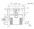
- the component mounting machine WM3 includes a substrate transfer device 11, a component supply device 12, a component transfer device 13, a component camera 14, a substrate camera 15, and a control device 16.
- the substrate transfer device 11 is configured by, for example, a belt conveyor and transfers the substrate 90 in the transfer direction (X-axis direction).
- the board 90 is a circuit board on which at least one of an electronic circuit and an electric circuit is formed.
- the board transfer device 11 carries the board 90 into the component mounting machine WM3 and positions the board 90 at a predetermined position in the machine.
- substrate conveyance apparatus 11 carries out the board
- the component supply device 12 supplies a plurality of components 91 mounted on the board 90.
- the component supply device 12 includes a plurality of feeders 121 provided along the conveyance direction (X-axis direction) of the substrate 90.
- Each of the plurality of feeders 121 feeds a carrier tape (not shown) in which a plurality of components 91 are housed with a pitch so that the components 91 can be collected at a supply position located on the tip side of the feeder 121.
- the component supply device 12 can also supply a relatively large electronic component (for example, a lead component) compared to a chip component or the like in a state of being arranged on the tray.
- the component transfer device 13 includes a head drive device 131 and a moving base 132.
- the head drive device 131 is configured to be able to move the movable table 132 in the X-axis direction and the Y-axis direction by a linear motion mechanism.
- the mounting head 20 is detachably (replaceable) provided on the moving base 132 by a clamp member (not shown).
- the mounting head 20 uses at least one holding member 50 to collect and hold the component 91 supplied by the component supply device 12, and mounts the component 91 on the substrate 90 positioned by the substrate transfer device 11.
- As the holding member 50 for example, a suction nozzle or a chuck can be used.
- a digital image pickup device having an image pickup element can be used.
- an image sensor for example, an image sensor such as a charge coupled device (CCD: Charge Coupled Device) or a complementary metal oxide semiconductor (CMOS: Complementary Metal Oxide Semiconductor) can be used.
- CCD Charge Coupled Device
- CMOS complementary metal oxide semiconductor
- the component camera 14 and the board camera 15 perform imaging based on a control signal sent from the control device 16. Image data captured by the component camera 14 and the board camera 15 is transmitted to the control device 16.
- the component camera 14 is fixed to the base of the component mounting machine WM3 so that the optical axis is upward in the Z-axis direction (vertical upward direction).
- the component camera 14 can image the component 91 held by the holding member 50 from below.
- the board camera 15 is provided on the moving base 132 of the component transfer device 13 such that the optical axis is downward in the Z-axis direction (downward in the vertical direction).
- the board camera 15 can take an image of the board 90 from above.
- the control device 16 includes a well-known central processing unit and a storage device, and constitutes a control circuit (both not shown).
- a central processing unit CPU: Central Processing Unit
- the storage device includes a first storage device and a second storage device.
- the first storage device is a volatile storage device (RAM: Random Access Memory)
- the second storage device is a non-volatile storage device (ROM: Read Only Memory).
- Information output from various sensors provided in the component mounting machine WM3, image data, and the like are input to the control device 16.
- the control device 16 sends a control signal to each device based on a control program and a predetermined mounting condition set in advance.
- the control device 16 causes the substrate camera 15 to capture an image of the substrate 90 carried in and positioned by the substrate transfer device 11.
- the control device 16 performs image processing on the image captured by the board camera 15 to recognize the positioning state of the board 90.
- the control device 16 can recognize the positioning state of the substrate 90 by grasping the positioning reference portion (not shown) provided on the substrate 90 by image processing, for example.
- the control device 16 causes the holding member 50 to collect and hold the component 91 supplied by the component supply device 12, and causes the component camera 14 to image the component 91 held by the holding member 50.
- the control device 16 performs image processing on the image captured by the component camera 14 to recognize the holding posture of the component 91.
- the control device 16 can recognize the holding posture of the component 91 by grasping, for example, a characteristic portion of the external appearance of the component 91 by image processing.
- the control device 16 moves the holding member 50 to the upper side of the planned mounting position preset by a control program or the like. Further, the control device 16 corrects the planned mounting position based on the positioning state of the board 90, the holding posture of the component 91, and the like, and sets the mounting position where the component 91 is actually mounted.
- the planned mounting position and the mounting position include a rotation angle in addition to the position (X-axis coordinate and Y-axis coordinate).
- the control device 16 corrects the target position (X-axis coordinate and Y-axis coordinate) and the rotation angle of the holding member 50 according to the mounting position.
- the controller 16 lowers the holding member 50 at the corrected target position at the corrected rotation angle, and mounts the component 91 on the board 90.
- the control device 16 executes the mounting process for mounting the plurality of components 91 on the board 90 by repeating the above-described pick and place cycle.
- the mounting head 20 includes a head main body 21 that is clamped to the moving base 132.
- the head main body 21 is provided with a rotary head 23 so that the R-axis motor 22 can determine a rotation angle for each predetermined angle.
- the rotary head 23 has a plurality of (for example, 12) tool shafts 24 arranged at equal intervals in the circumferential direction on a circle concentric with the R-axis, in the ⁇ -axis direction parallel to the Z-axis and the R-axis (vertical direction in FIG. ) So as to be slidable and rotatable about the ⁇ axis.
- the tool shaft 24 is biased upward with respect to the rotary head 23 by the elastic force of a spring (not shown). As a result, the tool shaft 24 is located at the rising end in the normal state where no external force is applied.
- a holding member 50 is detachably attached to the lower end of the tool shaft 24. At least positive pressure air or negative pressure air is supplied to the holding member 50, and the component 91 is sampled.
- the holding member 50 includes a suction nozzle that sucks the component 91 with negative pressure air, a chuck (not shown) that operates with positive pressure air or negative pressure air, and the like. Further, when the holding member 50 is attached to the tool shaft 24, the elastic force of an in-shaft spring (not shown) biases the holding member 50 downward.
- Each of the plurality of holding members 50 holds the component 91 by supplying air to the air passage of the holding member 50.
- the plurality of holding members 50 are sequentially indexed to predetermined angular positions around the R axis (for example, the vertical position of the tool shaft 24) by the rotation of the rotary head 23 as the R axis motor 22 is driven.
- the mounting head 20 includes a ⁇ -axis motor 25 fixed to the head body 21. All the tool shafts 24 are connected to the output shaft of the ⁇ -axis motor 25 so that the rotational force can be transmitted via a plurality of gears.
- the tool shaft 24 and the holding member 50 are integrally rotated (rotated) around the ⁇ axis by the operation of the ⁇ axis motor 25, and the rotation angle and the rotation speed are controlled.
- the head body 21 is provided with an operating member 26 that is movable in the Z-axis direction (vertical vertical direction).
- the actuating member 26 is moved up and down in the Z-axis direction by a ball screw mechanism 28 that is driven by the Z-axis motor 27.
- the actuating member 26 includes a lever 29 that comes into contact with the upper end of the tool shaft 24 that is indexed to the vertical position among the plurality of tool shafts 24.
- the lever 29 moves down as the actuating member 26 moves downward in the Z-axis direction.
- the lever 29 presses the tool shaft 24 downward in the Z-axis direction against the elastic force of the contacting spring of the tool shaft 24, and lowers the tool shaft 24.
- the tool shaft 24 and the holding member 50 are integrally moved up and down in the Z-axis direction by driving the Z-axis motor 27, and the Z-axis direction position and the moving speed are controlled.
- the drive unit 60 is detachably provided on the board-to-board working machine WM that performs a predetermined board-to-board work on the board 90.
- the drive unit 60 is not limited as long as it is a drive unit that is detachably provided on the board-to-board working machine WM.
- the moving head 60h performs the above.
- the work machine WM for a substrate is the printing machine WM1
- a printing head for printing solder, a soldering paste, a dispensing head for applying glue, and the like are included in the moving head 60h.
- the work machine WM for a substrate is an inspection machine such as the print inspection machine WM2 and the appearance inspection machine WM5
- the inspection head that moves on the substrate 90 is included in the moving head 60h.
- the driving unit 60 includes a holding member 50 that picks up and holds the component 91 and mounts it on the positioned substrate 90.
- a value of 20 is preferable.
- the mounting head 20 is moved by the component transfer device 13 to each of a plurality of work positions (a component suction position and a component mounting position) in the component mounting machine WM3, and the work for board (component suction work, Parts mounting work). That is, the mounting head 20 is included in the moving head 60h.
- the drive unit 60 includes a drive unit 61, a driven unit 62 driven by the drive unit 61, and a storage device 63.
- the drive unit 61 and the driven unit 62 can take various forms, but when the drive unit 60 is the moving head 60h, the drive unit 61 is the electric motor 61m, and the driven unit 62 is the lifting body 62e and the rotating body. It is preferable that it is at least one of 62r.
- the electric motor 61m various known DC motors and AC motors can be used.
- the mounting head 20 uses a servo motor, a stepping motor, or the like.
- the R-axis motor 22, the ⁇ -axis motor 25, and the Z-axis motor 27 shown in FIG. 3 are included in the electric motor 61m.
- the elevating body 62e is a portion that is moved in the vertical direction by driving the electric motor 61m.
- the tool shaft 24, the operating member 26, and the ball screw mechanism 28 shown in FIG. 3 are included in the elevating body 62e.
- the rotating body 62r is a part rotated by the drive of the electric motor 61m, and for example, the rotary head 23 and the tool shaft 24 shown in FIG. 3 are included in the rotating body 62r.
- a gear mechanism 25g including a gear portion 25a connected to the drive shaft of the ⁇ -axis motor 25 and a gear portion 25b connected to the drive shaft of the R-axis motor 22 and meshing with the gear portion 25a is included in the rotating body 62r. Be done.
- a publicly known storage device can be used as the storage device 63.
- the storage device 63 is preferably a non-volatile storage device, for example. In this case, the storage device 63 can continue to store data even when power is not supplied.
- a non-rewritable non-volatile storage device such as mascrom can be used.
- the storage device 63 can also be a rewritable non-volatile storage device such as a flash memory or an EEPROM (Electrically Erasable Programmable Read Only Memory).
- the unit management device 70 manages the drive unit 60.
- the driven portion 62 deteriorates.
- the disappearance of grease between the rotary head 23 and the tool shaft 24, the disappearance of grease of the ball screw mechanism 28, and the deformation of the tool shaft 24 shown in FIG. 3 are examples of deterioration of the driven portion 62.
- the loss of grease in the gear mechanism 25g, the wear of at least one of the gear portions 25a and 25b, and the entrapment of foreign matter (for example, dust) between the gear portions 25a and 25b may cause the driven portion. It is another example of the deterioration of 62.
- the unit management device 70 can determine whether maintenance of the driven portion 62 is necessary or not based on the change in the driving state of the driven portion 62.
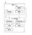
- the unit management device 70 when regarded as a control block, includes a reference value acquisition unit 71, a current value acquisition unit 72, and a determination unit 73. It is preferable that the unit management device 70 further includes at least one of the estimation unit 74 and the guide unit 75. As shown in FIG. 4, the unit management device 70 of the present embodiment includes a reference value acquisition unit 71, a current value acquisition unit 72, a determination unit 73, an estimation unit 74, and a guide unit 75. Further, as shown in FIG. 1, the unit management device 70 of the present embodiment is provided separately from the board working machine WM, but it may be provided in the board working machine WM. In this case, the unit management device 70 needs maintenance of the driven portion 62 during, for example, a standby time of the drive unit 60 (for example, during transportation of the substrate 90) or a rest time during which the work for the substrate is stopped. Can be judged.
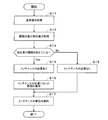
- the unit management device 70 executes the control program according to the flowchart shown in FIG.
- the reference value acquisition unit 71 performs the process shown in step S11.
- the current value acquisition unit 72 performs the process shown in step S12.
- the determination unit 73 makes the determination shown in step S13 and performs the processing shown in steps S14 and S15.
- the estimation unit 74 performs the process shown in step S16.
- the guide unit 75 performs the process shown in step S17.
- Reference value acquisition unit 71 acquires a reference value used when determining whether maintenance of the driven portion 62 is necessary from the storage device 63 of the drive unit 60 (step S11 shown in FIG. 5).
- the reference value is preferably set based on the driving state of the driven portion 62 when the driven portion 62 is first driven after being mounted on the drive unit 60. As a result, the unit management device 70 can determine whether maintenance of the driven portion 62 is necessary or not with reference to the initial state in which the driven portion 62 is not deteriorated.
- the manufacturer of the drive unit 60 drives the drive unit 61 under a predetermined drive condition before shipping the drive unit 60 to drive the driven unit 62 (hereinafter, referred to as “initial value of drive state”). ) To get.
- the driving unit 60 Before the driving unit 60 is shipped, it is an example of a state in which the driven portion 62 is not deteriorated, and includes, for example, a case where the driven portion 62 is replaced and first driven.
- the drive unit 61 is the electric motor 61m
- the reference value used when determining whether maintenance of the driven unit 62 is necessary is, for example, the output torque of the electric motor 61m when the drive unit 60 is driven according to a predetermined speed profile ( The driving state of the driven portion 62).
- the output torque of the electric motor 61m can be acquired, for example, based on the detected value of the input current of the electric motor 61m. Further, the output torque of the electric motor 61m can be directly detected by providing a torque detector on the drive shaft of the electric motor 61m, for example. Then, the manufacturer of the drive unit 60 stores the initial value of the drive state in the storage device 63 of the drive unit 60.
- the reference value acquisition unit 71 can acquire a reference value by adding a predetermined constant value to the initial value of the drive state stored in the storage device 63 of the drive unit 60.
- the manufacturer of the drive unit 60 can store the design value of the drive state in the storage device 63 of the drive unit 60 instead of the initial value of the drive state.
- the reference value acquisition unit 71 can acquire a reference value by adding a predetermined constant value to the design value of the drive state stored in the storage device 63 of the drive unit 60.
- the manufacturer of the drive unit 60 can store the reference value obtained by adding a predetermined constant value to the initial value or the design value of the drive state in the storage device 63 of the drive unit 60.
- the reference value acquisition unit 71 can read the reference value stored in the storage device 63 of the drive unit 60 and acquire the reference value.
- the predetermined constant value indicates an allowable range until the maintenance of the driven portion 62 becomes necessary, and may be a positive value or a negative value.
- the drive unit 60 includes a plurality of driven parts 62 that are selectively driven with respect to one driving part 61, there may be individual differences in the driving state of the driven parts 62.
- the rotary head 23 shown in FIG. 3 holds a plurality of (for example, 12) tool shafts 24 at equal intervals in the circumferential direction on a circle concentric with the R axis.
- the drive state of the driven part 62 (for example, the output torque of the electric motor 61m when rotating each tool shaft 24) may vary more than the allowable value.
- the reference value is preferably set for each of the plurality of driven parts 62.
- the unit management device 70 can determine the necessity of maintenance in consideration of the eigenvalues of the plurality of driven parts 62.
- the manufacturer of the drive unit 60 acquires the initial value of the drive state for each of the plurality of driven parts 62. Then, the manufacturer of the drive unit 60 causes the storage device 63 of the drive unit 60 to store the initial value of the drive state for each of the plurality of driven parts 62.
- the reference value acquisition unit 71 acquires a reference value by adding a predetermined constant value to the initial value of the driving state stored in the storage device 63 of the drive unit 60 for each of the plurality of driven units 62. You can
- the manufacturer of the drive unit 60 can store the reference value obtained by adding a predetermined constant value to the initial value of the drive state in the storage device 63 of the drive unit 60 for each of the plurality of driven parts 62. ..
- the reference value acquisition unit 71 can read the reference value stored in the storage device 63 of the drive unit 60 and acquire the reference value for each of the plurality of driven units 62.
- the current value acquisition unit 72 drives the drive unit 61 to acquire the current value of the drive state of the driven unit 62 (step S12 shown in FIG. 5).
- the current value acquisition unit 72 drives the drive unit 61 under the same drive conditions as when the initial value or the design value of the drive state is acquired, and acquires the current value of the drive state of the driven unit 62.
- the above description of the method of acquiring the drive state of the driven part 62 (for example, the output torque of the electric motor 61m) can be similarly applied to the current value acquisition part 72.
- Judgment unit 73 determines whether maintenance of the driven unit 62 is necessary based on the reference value acquired by the reference value acquisition unit 71 and the current value of the driving state acquired by the current value acquisition unit 72. The determination unit 73 compares the reference value acquired by the reference value acquisition unit 71 with the current value of the driving state acquired by the current value acquisition unit 72 to determine whether maintenance of the driven unit 62 is necessary. You can judge. Further, the determination unit 73 sets a threshold value based on the reference value, and the current value of the drive state of the driven unit 62 when the drive unit 61 is driven under a predetermined drive condition in which a constant drive state is expected is the threshold value. If it exceeds, it is preferable to judge that the driven portion 62 needs maintenance (steps S13 to S15 shown in FIG. 5).
- FIG. 6A shows an example of changes over time in the driving state of the driven part 62 when the driven part 62 is first driven after being mounted in the drive unit 60.
- the solid line L10 indicates the drive state of the driven portion 62 when the drive portion 61 (electric motor 61m) is driven under predetermined drive conditions (for example, speed control for driving according to a predetermined speed profile) in which a constant drive state is expected ( An example of a temporal change of the output torque of the electric motor 61m) is shown.
- the vertical axis represents the output torque of the electric motor 61m
- the horizontal axis represents the time.
- the output torque of the electric motor 61m gradually increases and becomes constant at the positive output torque Tq0 (hereinafter, referred to as "acceleration section”). After that, the output torque of the electric motor 61m becomes constant at an output torque smaller than the output torque Tq0 (hereinafter, referred to as “constant speed section”).
- the output torque of the electric motor 61m becomes constant with a negative output torque (hereinafter referred to as "deceleration section"), and when the electric motor 61m stops, the output torque of the electric motor 61m becomes zero. Become.
- the output torque Tq0 indicates the initial value of the driving state.
- the constant value C0 has shown the predetermined value added to output torque Tq0 (initial value of a drive state).
- the output torque Tq1 is an addition value obtained by adding the constant value C0 to the output torque Tq0, and corresponds to a threshold value set based on the reference value.
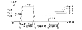
- FIG. 6B shows an example of a change over time in the drive state acquired by the current value acquisition unit 72.
- the driven portion 62 deteriorates.
- a solid line L11 indicates an example of a change over time of the driving state (output torque of the electric motor 61m) of the driven portion 62 when the driving portion 61 (electric motor 61m) is driven under the same driving condition as in FIG. 6A at this time.
- the vertical axis represents the output torque of the electric motor 61m
- the horizontal axis represents the time.
- the output torque of the electric motor 61m fluctuates similarly to the case of FIG. 6A depending on the acceleration section, the constant speed section and the deceleration section.
- the output torque of the electric motor 61m in the acceleration section is constant at the output torque Tq2.
- the output torque Tq2 is larger than the output torque Tq1 (threshold value set based on the reference value).
- time Tm11 indicates a time at which the current value of the output torque of the electric motor 61m (driving state of the driven portion 62) exceeds the output torque Tq1 (threshold value set based on the reference value)
- time Tm21 indicates the electric motor 61m. Shows the time at which the output torque of is equal to or less than the output torque Tq1.
- the determination unit 73 can determine whether maintenance of the driven unit 62 is necessary as follows.
- the determination unit 73 sets a threshold value at which the current value of the drive state of the driven unit 62 (output torque of the electric motor 61m) acquired by the current value acquisition unit 72 is set based on the reference value acquired by the reference value acquisition unit 71. It is determined whether (output torque Tq1) is exceeded (step S13 shown in FIG. 5).
- the determining portion 73 informs the driven portion 62 that the maintenance is not performed.
- step S14 It is determined that it is necessary (step S14).
- the determining part 73 does not require maintenance of the driven part 62. It is determined that there is (step S15).
- the determination unit 73 determines that the driven unit 62 needs maintenance.
- the determination unit 73 of the present embodiment sets the threshold value based on the reference value, and determines the current value of the drive state of the driven unit 62 when the drive unit 61 is driven under a predetermined drive condition in which a constant drive state is expected.
- the threshold value is exceeded, it is determined that the driven portion 62 needs maintenance.
- the unit management device 70 causes the maintenance factor (for example, disappearance of the grease applied to the driven portion 62, the amount of the grease applied to the driven portion 62, and the like) that the driven state of the driven portion 62 tends to increase as the driven portion 62 deteriorates. It is possible to determine whether or not the driven portion 62 needs to be maintained with respect to the deformation, wear, foreign matters, etc. of the driving portion 62.
- the determination unit 73 sets the threshold value based on the reference value, and the current value of the drive state of the driven unit 62 when the drive unit 61 is driven under a predetermined drive condition in which a constant drive state is expected is less than the threshold value. If it becomes smaller, it can be determined that maintenance of the driven portion 62 is necessary. In this case, the predetermined constant value C0 (the allowable range until the maintenance of the driven portion 62 is required) described above is a negative value. As a result, the unit management device 70 determines whether maintenance of the driven portion 62 is necessary or not for a maintenance factor that tends to decrease the driving state of the driven portion 62 as the driven portion 62 deteriorates. You can
- the current value acquisition part 72 includes a plurality of driven parts 62. Can be driven one by one in order. Further, when the drive unit 60 includes a plurality of driven parts 62 that are selectively driven with respect to one driving part 61, the current value acquisition part 72 causes the current value acquisition part 72 to interlock a predetermined one of the driven parts 62. It is also possible to drive a plurality of driven parts 62 at the same time. In this case, the reference value acquisition unit 71 acquires a reference value when a plurality of driven parts 62 are driven simultaneously.
- the storage device 63 preferably stores a plurality of reference values corresponding to each of the driven parts 62.
- the reference value acquisition unit 71 can acquire the reference value corresponding to each of the driven parts 62 from the storage device 63 of the drive unit 60.
- the determination unit 73 determines whether or not maintenance of the driven unit 62 is necessary for each of the plurality of driven units 62 based on the plurality of reference values corresponding to each of the driven units 62. Further, the determination unit 73 sets a threshold value for each of the plurality of driven units 62 based on the reference value, and the driven unit 62 when the driving unit 61 is driven under a predetermined driving condition in which a constant driving state is expected. When the current value of the drive state of exceeds the threshold value, it can be determined that the driven portion 62 needs maintenance.
- the determination unit 73 can also set a plurality of threshold values (output torques Tq10 to Tq13) according to the need for maintenance of the driven unit 62 based on the reference value.
- the output torque Tq10 is set to be smaller than the threshold value (output torque Tq1), and the need for maintenance of the driven portion 62 is the lowest among the plurality of threshold values (output torque Tq10 to Tq13).
- the notice level is shown.
- the output torque Tq11, the output torque Tq12, and the output torque Tq13 are set to be larger than the threshold value (output torque Tq1), and the necessity level of the maintenance of the driven portion 62 increases in this order.
- the plurality of threshold values can be set at equal intervals. What has been described above regarding a plurality of threshold values (output torques Tq10 to Tq13) can be similarly applied to the examples shown in FIGS. 6C and 6D.
- the determination unit 73 obtains the necessity level of maintenance of the driven unit 62 according to the threshold value compared with the current value of the driving state. For example, when the threshold value compared with the current value of the driving state of the driven portion 62 is the output torque Tq13, the determining unit 73 acquires the maintenance necessity degree of the driven portion 62 indicated by the output torque Tq13. Specifically, the output torque Tq13 is the highest among the plurality of threshold values (output torques Tq10 to Tq13), and the degree of maintenance of the driven portion 62 indicates, for example, the level at which urgent maintenance is required.
- the determination unit 73 can acquire the necessity level of maintenance of the driven unit 62 according to the threshold value compared with the current value of the driving state.
- the determination unit 73 of the present embodiment determines whether maintenance of the driven unit 62 is necessary in the acceleration section, but the determination unit 73 determines whether maintenance of the driven unit 62 is necessary in the constant speed section. You can also do it.
- the determining unit 73 can also determine whether maintenance of the driven unit 62 is necessary in the deceleration section. That is, the determination unit 73 can determine the necessity of maintenance of the driven unit 62 by setting thresholds corresponding to the acceleration section, the constant speed section, and the deceleration section.
- Estimator 74 When the determining unit 73 determines that the driven unit 62 needs maintenance, the estimating unit 74 determines the maintenance of the driven unit 62 based on the change over time of the current value of the driving state acquired by the current value acquiring unit 72. Estimate the factors that required maintenance. It is preferable that the estimation unit 74 estimates the factor that requires the maintenance of the driven unit 62 based on the timing when the current value of the driving state exceeds the threshold value and the duration time when the current value of the driving state exceeds the threshold value. Is.
- FIG. 6C shows another example of the change over time of the driving state acquired by the current value acquisition unit 72.
- a solid line L12 shows an example of a temporal change in the driving state (output torque of the electric motor 61m) of the driven portion 62 when the driving portion 61 (electric motor 61m) is driven under the same driving condition as in FIG. 6A.
- the vertical axis represents the output torque of the electric motor 61m
- the horizontal axis represents the time.
- the output torque of the electric motor 61m fluctuates in the same manner as in the case of FIG. 6A depending on the acceleration section, the constant speed section and the deceleration section.
- the output torque of the electric motor 61m in the acceleration section increases from the output torque Tq0 to reach the output torque Tq3, and then returns to the output torque Tq0.
- the output torque Tq3 is larger than the output torque Tq1 (threshold value set based on the reference value).
- time Tm12 indicates a time at which the output torque of the electric motor 61m (driving state of the driven portion 62) exceeds the output torque Tq1 (threshold value set based on the reference value), and time Tm22 indicates an output torque of the electric motor 61m. Indicates the time when the output torque becomes Tq1 or less.
- FIG. 6D shows another example of the change over time of the driving state acquired by the current value acquisition unit 72.
- a solid line L13 shows an example of a temporal change of the driving state (output torque of the electric motor 61m) of the driven portion 62 when the driving portion 61 (electric motor 61m) is driven under the same driving condition as in FIG. 6A.
- the vertical axis represents the output torque of the electric motor 61m
- the horizontal axis represents the time.
- the output torque of the electric motor 61m fluctuates similarly to the case of FIG. 6A depending on the acceleration section, the constant speed section and the deceleration section.
- the output torque of the electric motor 61m in the acceleration section increases and decreases in a sinusoidal manner.
- the lower limit value of the output torque of the electric motor 61m, which increases/decreases sinusoidally, is indicated by the output torque Tq41, and the upper limit value of the output torque is indicated by the output torque Tq42.
- the output torque Tq42 is larger than the output torque Tq1 (threshold value set based on the reference value). Further, time Tm13 indicates the time when the output torque of the electric motor 61m (driving state of the driven portion 62) exceeds the output torque Tq1 (threshold value set based on the reference value), and time Tm23 indicates the output torque of the electric motor 61m. Indicates the time when the output torque becomes Tq1 or less. The above-described state is repeated according to the output torque of the electric motor 61m that increases and decreases in a sinusoidal manner.
- the estimation unit 74 can estimate that the disappearance of the grease applied to the driven unit 62 is a factor, for example. The disappearance of grease is likely to occur in a wide range in the driven portion 62, and the output torque of the electric motor 61m (driving state of the driven portion 62) is likely to increase as a whole.
- the estimation unit 74 can estimate that the foreign matter is mixed in the driven unit 62, for example. The foreign matter is likely to be locally generated in the driven portion 62, and the output torque of the electric motor 61m (driving state of the driven portion 62) is likely to be locally increased in the foreign matter mixed portion.
- the estimation unit 74 can estimate that the deformation or wear of the driven unit 62 is a factor, for example.
- the unit management device 70 of the present embodiment includes the estimation unit 74, it is possible to estimate the factor that requires the maintenance of the driven unit 62.
- the examples shown in FIGS. 6B to 6D are examples, and the factors that require maintenance of the driven portion 62 are not limited to these.
- Guide 75 guides the user of the working machine WM to the substrate whether or not the maintenance of the driven unit 62 determined by the determination unit 73 is necessary. Accordingly, the user of the working machine WM for a board can know whether maintenance of the driven portion 62 is necessary or not, and the maintenance of the driven portion 62 can be performed.
- the guide unit 75 displays, for example, the driven unit 62 that has determined whether maintenance is required and the determination result (maintenance required or not required) on a known display device (not shown). You can Further, the guide part 75 can also display the necessity level of maintenance of the driven part 62 on the display device. Further, the guide part 75 can also display the cause of the maintenance of the driven part 62 on the display device. Further, the guide part 75 can also display the maintenance method of the driven part 62 on the display device.
- the maintenance method is to replenish the grease, and the manufacturer of the board working machine WM replenishes the grease according to the guide.
- the maintenance method is removal of the foreign matter, and the manufacturer of the board working machine WM removes the foreign matter according to the guide. Remove.
- the maintenance method is adjustment, repair or replacement of the driven portion 62, and manufacturing of the work machine WM for a substrate. The person adjusts, repairs, or replaces the driven portion 62 according to the guidance.
- the drive unit 60 is preferably the feeder 121 that supplies the component 91.
- Each of the plurality of feeders 121 includes a sprocket and a drive device that rotationally drives the sprocket (all not shown).
- the sprocket pitch-feeds a carrier tape containing a plurality of components 91.
- the drive device for example, a positionable electric motor such as a stepping motor or a servo motor can be used.
- the drive device corresponds to the drive unit 61, and the reduction mechanism and the sprocket connected to the drive shaft of the electric motor correspond to the driven unit 62.
- a storage device 63 can be provided in the control device that controls the driving of the electric motor.
- the unit management method includes a reference value acquisition step, a current value acquisition step, and a determination step.
- the reference value acquisition step corresponds to the control performed by the reference value acquisition unit 71.
- the current value acquisition step corresponds to the control performed by the current value acquisition unit 72.
- the determination step corresponds to the control performed by the determination unit 73.
- the unit management method includes at least one of the estimation step and the guidance step.
- the estimation step corresponds to the control performed by the estimation unit 74.
- the guidance process corresponds to the control performed by the guide unit 75.
- the unit management device 70 includes a reference value acquisition unit 71, a current value acquisition unit 72, and a determination unit 73.
- the reference value acquisition unit 71 acquires, from the storage device 63 of the drive unit 60, a reference value used when determining whether maintenance of the driven unit 62 is necessary. Therefore, the unit management device 70 can easily acquire the reference value.
- the determination unit 73 also determines whether maintenance of the driven unit 62 is necessary based on the reference value acquired by the reference value acquisition unit 71 and the current value of the driving state acquired by the current value acquisition unit 72. Therefore, the unit management device 70 can easily determine whether or not the driven portion 62 included in the drive unit 60 needs maintenance. What has been described above regarding the unit management apparatus 70 can be similarly applied to the unit management method.
- 60 drive unit, 60h: moving head, 61: drive unit, 61m: electric motor, 62: driven part, 62e: lifting body, 62r: rotating body, 63: storage device, 70: unit management device, 71: reference value acquisition unit, 72: current value acquisition unit, 73: judgment part, 74: estimation part, 75: guide part, 90: substrate, 91: component, 50: holding member, 20: mounting head, 121: feeder, WM: work machine for board, WM3: component mounting machine.
Landscapes
- Engineering & Computer Science (AREA)
- Manufacturing & Machinery (AREA)
- Microelectronics & Electronic Packaging (AREA)
- Supply And Installment Of Electrical Components (AREA)
Abstract
ユニット管理装置は、基板に所定の対基板作業を行う対基板作業機に着脱可能に設けられ、かつ、駆動部と駆動部によって駆動される被駆動部と記憶装置とを備える駆動ユニットを管理する。ユニット管理装置は、基準値取得部と、現在値取得部と、判断部とを具備する。基準値取得部は、被駆動部のメンテナンスの要否を判断する際に用いる基準値を、駆動ユニットの記憶装置から取得する。現在値取得部は、駆動部を駆動させて被駆動部の駆動状態の現在値を取得する。判断部は、基準値取得部によって取得された基準値と現在値取得部によって取得された駆動状態の現在値とに基づき被駆動部のメンテナンスの要否を判断する。
Description
本明細書は、ユニット管理装置およびユニット管理方法に関する技術を開示する。
特許文献1に記載の状態監視装置は、駆動状態検知手段と、判定手段とを備えている。駆動状態検知手段は、駆動系の駆動状態を検知する。判定手段は、検知された駆動系の駆動状態が正常状態、異常状態、異常状態に至る前の異常予兆状態のうちのいずれの状態にあるかを判定する状態判定を行う。また、駆動状態検知手段は、駆動制御によりモータから出力される出力トルクを検知または推定する出力トルク検知推定手段を有しており、判定手段は、検知若しくは推定された出力トルク、または、出力トルクの変化に基づき、状態判定を行う。これらにより、特許文献1に記載の状態監視装置は、部品装着機が生産中に異常停止することを抑制しようとしている。
しかしながら、特許文献1は、判定手段が状態判定の際に用いる基準値の格納場所を開示するものではない。例えば、複数の部品装着機の各々の制御装置に基準値が記憶されていると、状態判定を行う際に制御装置から基準値を読み出す必要があり、判定作業が煩雑になる可能性がある。特に、基板に所定の対基板作業を行う対基板作業機に着脱可能に設けられる駆動ユニットでは、駆動ユニットの取り付け位置が対基板作業に応じて変更される可能性がある。そのため、駆動ユニットごとの基準値の管理がさらに煩雑になる可能性がある。
このような事情に鑑みて、本明細書は、対基板作業機に着脱可能に設けられる駆動ユニットが備える被駆動部のメンテナンスの要否を容易に判断可能なユニット管理装置およびユニット管理方法を開示する。
本明細書は、基板に所定の対基板作業を行う対基板作業機に着脱可能に設けられ、かつ、駆動部と前記駆動部によって駆動される被駆動部と記憶装置とを備える駆動ユニットを管理するユニット管理装置を開示する。前記ユニット管理装置は、基準値取得部と、現在値取得部と、判断部とを具備する。前記基準値取得部は、前記被駆動部のメンテナンスの要否を判断する際に用いる基準値を、前記駆動ユニットの前記記憶装置から取得する。前記現在値取得部は、前記駆動部を駆動させて前記被駆動部の駆動状態の現在値を取得する。前記判断部は、前記基準値取得部によって取得された前記基準値と前記現在値取得部によって取得された前記駆動状態の前記現在値とに基づき前記被駆動部のメンテナンスの要否を判断する。
また、本明細書は、基板に所定の対基板作業を行う対基板作業機に着脱可能に設けられ、かつ、駆動部と前記駆動部によって駆動される被駆動部と記憶装置とを備える駆動ユニットを管理するユニット管理方法を開示する。前記ユニット管理方法は、基準値取得工程と、現在値取得工程と、判断工程とを具備する。前記基準値取得工程は、前記被駆動部のメンテナンスの要否を判断する際に用いる基準値を、前記駆動ユニットの前記記憶装置から取得する。前記現在値取得工程は、前記駆動部を駆動させて前記被駆動部の駆動状態の現在値を取得する。前記判断工程は、前記基準値取得工程によって取得された前記基準値と前記現在値取得工程によって取得された前記駆動状態の前記現在値とに基づき前記被駆動部のメンテナンスの要否を判断する。
上記のユニット管理装置によれば、基準値取得部と、現在値取得部と、判断部とを具備する。基準値取得部は、被駆動部のメンテナンスの要否を判断する際に用いる基準値を、駆動ユニットの記憶装置から取得する。そのため、ユニット管理装置は、基準値の取得が容易である。また、判断部は、基準値取得部によって取得された基準値と現在値取得部によって取得された駆動状態の現在値とに基づき被駆動部のメンテナンスの要否を判断する。よって、ユニット管理装置は、駆動ユニットが備える被駆動部のメンテナンスの要否を容易に判断することができる。ユニット管理装置について上述したことは、ユニット管理方法についても同様に言える。
1.実施形態
1-1.対基板作業ラインWMLの構成例
対基板作業ラインWMLでは、基板90に所定の対基板作業を行う。対基板作業ラインWMLを構成する対基板作業機WMの種類および数は、限定されない。図1に示すように、本実施形態の対基板作業ラインWMLは、印刷機WM1、印刷検査機WM2、部品装着機WM3、リフロー炉WM4および外観検査機WM5の複数(5つ)の対基板作業機WMを備えている。複数(5つ)の対基板作業機WMは、上流側から、印刷機WM1、印刷検査機WM2、部品装着機WM3、リフロー炉WM4、外観検査機WM5の順に配置されている。基板90は、対基板作業ラインWMLの先頭に位置する印刷機WM1に搬入される。そして、基板90は、対基板作業ラインWMLの基板搬送装置(図示略)によって下流側へ搬送され、対基板作業ラインWMLの末尾に位置する外観検査機WM5から搬出される。
1-1.対基板作業ラインWMLの構成例
対基板作業ラインWMLでは、基板90に所定の対基板作業を行う。対基板作業ラインWMLを構成する対基板作業機WMの種類および数は、限定されない。図1に示すように、本実施形態の対基板作業ラインWMLは、印刷機WM1、印刷検査機WM2、部品装着機WM3、リフロー炉WM4および外観検査機WM5の複数(5つ)の対基板作業機WMを備えている。複数(5つ)の対基板作業機WMは、上流側から、印刷機WM1、印刷検査機WM2、部品装着機WM3、リフロー炉WM4、外観検査機WM5の順に配置されている。基板90は、対基板作業ラインWMLの先頭に位置する印刷機WM1に搬入される。そして、基板90は、対基板作業ラインWMLの基板搬送装置(図示略)によって下流側へ搬送され、対基板作業ラインWMLの末尾に位置する外観検査機WM5から搬出される。
印刷機WM1は、基板90において、複数の部品91の各々の装着位置に、はんだを印刷する。基板90に印刷されるはんだは、ペースト状であり、所定の粘性を備える。はんだは、基板90と、基板90に装着される複数の部品91とを接合する接合材として機能する。印刷検査機WM2は、印刷機WM1によって印刷されたはんだの印刷状態を検査する。部品装着機WM3は、印刷機WM1によって印刷されたはんだの上に複数の部品91を装着する。部品装着機WM3は、一つであっても良く、複数であっても良い。部品装着機WM3が複数設けられる場合は、複数の部品装着機WM3が分担して、複数の部品91を装着することができる。
リフロー炉WM4は、部品装着機WM3によって複数の部品91が装着された基板90を加熱し、はんだを溶融させて、はんだ付けを行う。外観検査機WM5は、部品装着機WM3によって装着された複数の部品91の装着状態などを検査する。具体的には、外観検査機WM5は、基板90に装着された複数の部品91の各々の適否、複数の部品91の各々の装着状態(X軸座標、Y軸座標および装着角度)などを認識し、管理装置WMCに送出する。このように、対基板作業ラインWMLは、複数(5つ)の対基板作業機WMを用いて、基板90を順に搬送し、検査処理を含む生産処理を実行して基板製品900を生産することができる。
なお、対基板作業ラインWMLは、例えば、対基板作業機WMである機能検査機を備えることができる。機能検査機は、リフロー炉WM4によって、はんだ付けされた基板90の機能検査を行う。また、対基板作業ラインWMLは、例えば、生産する基板製品900の種類などに応じて、対基板作業ラインWMLの構成を適宜追加することができ、構成を適宜変更することができる。対基板作業ラインWMLは、例えば、バッファ装置、基板供給装置、基板反転装置、シールド装着装置、接着剤塗布装置、紫外線照射装置などの対基板作業機WMを備えることもできる。
対基板作業ラインWMLを構成する複数(5つ)の対基板作業機WMおよび管理装置WMCは、通信部LCによって電気的に接続されている。通信部LCは、有線であっても良く、無線であっても良い。また、通信方法は、種々の方法をとり得る。本実施形態では、複数(5つ)の対基板作業機WMおよび管理装置WMCによって、構内情報通信網(LAN:Local Area Network)が構成されている。これにより、複数(5つ)の対基板作業機WMは、通信部LCを介して、互いに通信することができる。また、複数(5つ)の対基板作業機WMは、通信部LCを介して、管理装置WMCと通信することができる。
管理装置WMCは、対基板作業ラインWMLを構成する複数(5つ)の対基板作業機WMの制御を行い、対基板作業ラインWMLの動作状況を監視する。管理装置WMCには、複数(5つ)の対基板作業機WMを制御する種々の制御データが記憶されている。管理装置WMCは、複数(5つ)の対基板作業機WMの各々に制御データを送信する。また、複数(5つ)の対基板作業機WMの各々は、管理装置WMCに動作状況および生産状況を送信する。
管理装置WMCには、例えば、画像保存サーバ、生産情報サーバなどの種々のデータサーバを設けることができる(いずれも図示略)。画像保存サーバは、対基板作業機WMによって撮像された種々の画像データを保存することができる。生産情報サーバは、基板90の生産に関する種々の生産情報を保存することができる。例えば、生産情報に含まれる部品データは、部品91の種類毎の形状に関する情報、電気的特性に関する情報、部品91の取り扱い方法に関する情報などを含んでいる。また、印刷検査機WM2、外観検査機WM5などの検査機による検査結果は、生産情報に含まれる。
1-2.部品装着機WM3の構成例
部品装着機WM3は、基板90に複数の部品91を装着する。図2に示すように、部品装着機WM3は、基板搬送装置11、部品供給装置12、部品移載装置13、部品カメラ14、基板カメラ15および制御装置16を備えている。基板搬送装置11は、例えば、ベルトコンベアなどにより構成され、基板90を搬送方向(X軸方向)に搬送する。基板90は、回路基板であり、電子回路および電気回路のうちの少なくとも一方が形成される。基板搬送装置11は、部品装着機WM3の機内に基板90を搬入すると共に、機内の所定位置に基板90を位置決めする。基板搬送装置11は、部品装着機WM3による複数の部品91の装着処理が終了した後に、基板90を部品装着機WM3の機外に搬出する。
部品装着機WM3は、基板90に複数の部品91を装着する。図2に示すように、部品装着機WM3は、基板搬送装置11、部品供給装置12、部品移載装置13、部品カメラ14、基板カメラ15および制御装置16を備えている。基板搬送装置11は、例えば、ベルトコンベアなどにより構成され、基板90を搬送方向(X軸方向)に搬送する。基板90は、回路基板であり、電子回路および電気回路のうちの少なくとも一方が形成される。基板搬送装置11は、部品装着機WM3の機内に基板90を搬入すると共に、機内の所定位置に基板90を位置決めする。基板搬送装置11は、部品装着機WM3による複数の部品91の装着処理が終了した後に、基板90を部品装着機WM3の機外に搬出する。
部品供給装置12は、基板90に装着される複数の部品91を供給する。部品供給装置12は、基板90の搬送方向(X軸方向)に沿って設けられる複数のフィーダ121を備えている。複数のフィーダ121の各々は、複数の部品91が収納されるキャリアテープ(図示略)をピッチ送りさせて、フィーダ121の先端側に位置する供給位置において部品91を採取可能に供給する。また、部品供給装置12は、チップ部品などと比べて比較的大型の電子部品(例えば、リード部品など)を、トレイ上に配置した状態で供給することもできる。
部品移載装置13は、ヘッド駆動装置131および移動台132を備えている。ヘッド駆動装置131は、直動機構により移動台132を、X軸方向およびY軸方向に移動可能に構成されている。移動台132には、クランプ部材(図示略)により装着ヘッド20が着脱可能(交換可能)に設けられている。装着ヘッド20は、少なくとも一つの保持部材50を用いて、部品供給装置12によって供給される部品91を採取し保持して、基板搬送装置11によって位置決めされた基板90に部品91を装着する。保持部材50は、例えば、吸着ノズル、チャックなどを用いることができる。
部品カメラ14および基板カメラ15は、例えば、撮像素子を有するデジタル式の撮像装置を用いることができる。撮像素子は、例えば、電荷結合素子(CCD:Charge Coupled Device)または相補型金属酸化膜半導体(CMOS:Complementary Metal Oxide Semiconductor)などのイメージセンサを用いることができる。部品カメラ14および基板カメラ15は、制御装置16から送出される制御信号に基づき撮像を行う。部品カメラ14および基板カメラ15によって撮像された画像データは、制御装置16に送信される。
部品カメラ14は、光軸がZ軸方向の上向き(鉛直上方方向)になるように、部品装着機WM3の基台に固定されている。部品カメラ14は、保持部材50によって保持されている部品91を下方から撮像することができる。基板カメラ15は、光軸がZ軸方向の下向き(鉛直下方方向)になるように、部品移載装置13の移動台132に設けられている。基板カメラ15は、基板90を上方から撮像することができる。
制御装置16は、公知の中央演算装置および記憶装置を備えており、制御回路が構成されている(いずれも図示略)。中央演算装置(CPU:Central Processing Unit)は、種々の演算処理を行うことができる。記憶装置は、第一記憶装置および第二記憶装置を備えている。第一記憶装置は、揮発性の記憶装置(RAM:Random Access Memory)であり、第二記憶装置は、不揮発性の記憶装置(ROM:Read Only Memory)である。制御装置16には、部品装着機WM3に設けられている各種センサから出力される情報、画像データなどが入力される。制御装置16は、制御プログラムおよび予め設定されている所定の装着条件などに基づき、各装置に対して制御信号を送出する。
例えば、制御装置16は、基板搬送装置11によって搬入され位置決めされた基板90を基板カメラ15に撮像させる。制御装置16は、基板カメラ15によって撮像された画像を画像処理して、基板90の位置決め状態を認識する。制御装置16は、例えば、基板90に設けられている位置決め基準部(図示略)などを画像処理によって把握して、基板90の位置決め状態を認識することができる。また、制御装置16は、部品供給装置12によって供給された部品91を保持部材50に採取させ保持させて、保持部材50に保持されている部品91を部品カメラ14に撮像させる。制御装置16は、部品カメラ14によって撮像された画像を画像処理して、部品91の保持姿勢を認識する。制御装置16は、例えば、部品91の外観で特徴的な部位などを画像処理によって把握して、部品91の保持姿勢を認識することができる。
制御装置16は、制御プログラムなどによって予め設定される装着予定位置の上方に向かって、保持部材50を移動させる。また、制御装置16は、基板90の位置決め状態、部品91の保持姿勢などに基づき、装着予定位置を補正して、実際に部品91を装着する装着位置を設定する。装着予定位置および装着位置は、位置(X軸座標およびY軸座標)の他に回転角度を含む。制御装置16は、装着位置に合わせて、保持部材50の目標位置(X軸座標およびY軸座標)および回転角度を補正する。制御装置16は、補正された目標位置において補正された回転角度で保持部材50を下降させて、基板90に部品91を装着する。制御装置16は、上記のピックアンドプレースサイクルを繰り返すことによって、基板90に複数の部品91を装着する装着処理を実行する。
1-3.装着ヘッド20の構成例
図3に示すように、装着ヘッド20は、移動台132にクランプされるヘッド本体21を備えている。ヘッド本体21には、R軸モータ22によって所定の角度ごとに回転角度を割り出し可能に、ロータリヘッド23が設けられている。ロータリヘッド23は、R軸と同心の円周上において周方向に等間隔に複数(例えば、12本)のツール軸24を、Z軸およびR軸に平行なθ軸方向(図3の上下方向)に摺動可能に且つθ軸周りに回転可能に保持する。
図3に示すように、装着ヘッド20は、移動台132にクランプされるヘッド本体21を備えている。ヘッド本体21には、R軸モータ22によって所定の角度ごとに回転角度を割り出し可能に、ロータリヘッド23が設けられている。ロータリヘッド23は、R軸と同心の円周上において周方向に等間隔に複数(例えば、12本)のツール軸24を、Z軸およびR軸に平行なθ軸方向(図3の上下方向)に摺動可能に且つθ軸周りに回転可能に保持する。
ツール軸24は、スプリング(図示略)の弾性力によりロータリヘッド23に対して上方に付勢されている。これにより、ツール軸24は、外力が付与されていない通常状態では、上昇端に位置している。ツール軸24の下端部には、保持部材50が着脱可能に取り付けられる。保持部材50には、少なくとも正圧エアまたは負圧エアが供給され、部品91を採取する。保持部材50には、負圧エアにより部品91を吸着する吸着ノズルの他に、正圧エアまたは負圧エアにより動作するチャック(図示略)などが含まれる。また、ツール軸24は、保持部材50が取り付けられると、軸内スプリング(図示略)の弾性力により、保持部材50を下方に付勢する。
複数の保持部材50の各々は、保持部材50のエア通路にエアが供給されて部品91を保持する。複数の保持部材50は、R軸モータ22の駆動に伴ってロータリヘッド23が回転することにより、R軸周りの所定の角度位置(例えば、ツール軸24の昇降位置)に順次割り出される。図3に示すように、装着ヘッド20は、ヘッド本体21に固定されたθ軸モータ25を備えている。θ軸モータ25の出力軸には、複数のギヤを介して回転力を伝達可能に全てのツール軸24が連結されている。ツール軸24および保持部材50は、θ軸モータ25の動作によりθ軸周りに一体的に回転(自転)し、回転角度や回転速度が制御される。
また、ヘッド本体21には、Z軸方向(鉛直上下方向)に移動可能に作動部材26が設けられている。作動部材26は、Z軸モータ27の駆動によって動作するボールねじ機構28によりZ軸方向に昇降する。作動部材26は、複数のツール軸24のうちの昇降位置に割り出されたツール軸24の上端部に接触するレバー29を備えている。レバー29は、作動部材26のZ軸方向下方への移動に伴って下降する。レバー29は、接触するツール軸24のスプリングの弾性力に抗してツール軸24をZ軸方向の下方へと押圧し、ツール軸24を下降させる。ツール軸24および保持部材50は、Z軸モータ27の駆動によりZ軸方向に一体的に昇降し、Z軸方向位置や移動速度が制御される。
1-4.駆動ユニット60の構成例
駆動ユニット60は、基板90に所定の対基板作業を行う対基板作業機WMに着脱可能に設けられる。駆動ユニット60は、対基板作業機WMに着脱可能に設けられる駆動ユニットであれば良く限定されないが、駆動ユニット60は、対基板作業機WMにおいて複数の作業位置の各々に移動して対基板作業を行う移動ヘッド60hであると好適である。例えば、対基板作業機WMが印刷機WM1の場合、はんだを印刷する印刷ヘッド、はんだペースト、グルーを塗布するディスペンスヘッドなどは、移動ヘッド60hに含まれる。また、対基板作業機WMが印刷検査機WM2、外観検査機WM5などの検査機の場合、基板90上を移動する検査ヘッドは、移動ヘッド60hに含まれる。
駆動ユニット60は、基板90に所定の対基板作業を行う対基板作業機WMに着脱可能に設けられる。駆動ユニット60は、対基板作業機WMに着脱可能に設けられる駆動ユニットであれば良く限定されないが、駆動ユニット60は、対基板作業機WMにおいて複数の作業位置の各々に移動して対基板作業を行う移動ヘッド60hであると好適である。例えば、対基板作業機WMが印刷機WM1の場合、はんだを印刷する印刷ヘッド、はんだペースト、グルーを塗布するディスペンスヘッドなどは、移動ヘッド60hに含まれる。また、対基板作業機WMが印刷検査機WM2、外観検査機WM5などの検査機の場合、基板90上を移動する検査ヘッドは、移動ヘッド60hに含まれる。
さらに、対基板作業機WMが部品装着機WM3の場合、図3に示すように、駆動ユニット60は、部品91を採取し保持して位置決めされた基板90に装着する保持部材50を備える装着ヘッド20であると好適である。既述したように、装着ヘッド20は、部品装着機WM3において複数の作業位置(部品吸着位置および部品装着位置)の各々に部品移載装置13によって移動して、対基板作業(部品吸着作業、部品装着作業)を行う。つまり、装着ヘッド20は、移動ヘッド60hに含まれる。
図4に示すように、駆動ユニット60は、駆動部61と、駆動部61によって駆動される被駆動部62と、記憶装置63とを備える。駆動部61および被駆動部62は、種々の形態をとり得るが、駆動ユニット60が移動ヘッド60hの場合、駆動部61は、電動機61mであり、被駆動部62は、昇降体62eおよび回転体62rのうちの少なくとも一方であると好適である。電動機61mは、公知の種々の直流モータ、交流モータを用いることができる。例えば、装着ヘッド20では、サーボモータ、ステッピングモータなどが用いられる。図3に示すR軸モータ22、θ軸モータ25およびZ軸モータ27は、電動機61mに含まれる。
昇降体62eは、電動機61mの駆動によって鉛直方向に移動される部位であり、例えば、図3に示すツール軸24、作動部材26およびボールねじ機構28は、昇降体62eに含まれる。回転体62rは、電動機61mの駆動によって回転される部位であり、例えば、図3に示すロータリヘッド23およびツール軸24は、回転体62rに含まれる。また、θ軸モータ25の駆動軸に連結されている歯車部25aと、R軸モータ22の駆動軸に連結され歯車部25aと噛み合う歯車部25bとを備える歯車機構25gは、回転体62rに含まれる。
記憶装置63は、公知の記憶装置を用いることができる。記憶装置63は、例えば、不揮発性の記憶装置を用いると好適である。この場合、記憶装置63は、電力が供給されていない状態においても、データを記憶し続けることができる。記憶装置63は、例えば、マスクロムなどの書き換え不可能な不揮発性の記憶装置を用いることができる。また、記憶装置63は、例えば、フラッシュメモリ、EEPROM(Electrically Erasable Programmable Read Only Memory)などの書き換え可能な不揮発性の記憶装置を用いることもできる。
1-5.ユニット管理装置70の構成例
ユニット管理装置70は、駆動ユニット60を管理する。駆動ユニット60が基板製品900の生産に使用されるにつれて、被駆動部62に劣化が生じる。例えば、図3に示すロータリヘッド23とツール軸24との間のグリスの消失、ボールねじ機構28のグリスの消失、ツール軸24の変形は、被駆動部62の劣化の一例である。また、歯車機構25gのグリスの消失、歯車部25aおよび歯車部25bのうちの少なくとも一方の摩耗、歯車部25aと歯車部25bとの間における異物(例えば、埃など)の挟み込みは、被駆動部62の劣化の他の一例である。このように、被駆動部62に劣化が生じると、被駆動部62の駆動状態が劣化前と比べて変化する。そのため、ユニット管理装置70は、被駆動部62の駆動状態の変化に基づき、被駆動部62のメンテナンスの要否を判断することができる。
ユニット管理装置70は、駆動ユニット60を管理する。駆動ユニット60が基板製品900の生産に使用されるにつれて、被駆動部62に劣化が生じる。例えば、図3に示すロータリヘッド23とツール軸24との間のグリスの消失、ボールねじ機構28のグリスの消失、ツール軸24の変形は、被駆動部62の劣化の一例である。また、歯車機構25gのグリスの消失、歯車部25aおよび歯車部25bのうちの少なくとも一方の摩耗、歯車部25aと歯車部25bとの間における異物(例えば、埃など)の挟み込みは、被駆動部62の劣化の他の一例である。このように、被駆動部62に劣化が生じると、被駆動部62の駆動状態が劣化前と比べて変化する。そのため、ユニット管理装置70は、被駆動部62の駆動状態の変化に基づき、被駆動部62のメンテナンスの要否を判断することができる。
ユニット管理装置70は、制御ブロックとして捉えると、基準値取得部71と、現在値取得部72と、判断部73とを備えている。ユニット管理装置70は、推定部74および案内部75のうちの少なくとも一方をさらに備えると好適である。図4に示すように、本実施形態のユニット管理装置70は、基準値取得部71と、現在値取得部72と、判断部73と、推定部74と、案内部75とを備えている。また、図1に示すように、本実施形態のユニット管理装置70は、対基板作業機WMと別体に設けられているが、対基板作業機WMに設けることもできる。この場合、ユニット管理装置70は、例えば、駆動ユニット60の待機時間(例えば、基板90の搬送中など)、対基板作業が休止している休止時間などに、被駆動部62のメンテナンスの要否を判断することができる。
また、ユニット管理装置70は、図5に示すフローチャートに従って、制御プログラムを実行する。基準値取得部71は、ステップS11に示す処理を行う。現在値取得部72は、ステップS12に示す処理を行う。判断部73は、ステップS13に示す判断を行い、ステップS14およびステップS15に示す処理を行う。推定部74は、ステップS16に示す処理を行う。案内部75は、ステップS17に示す処理を行う。
1-5-1.基準値取得部71
基準値取得部71は、被駆動部62のメンテナンスの要否を判断する際に用いる基準値を、駆動ユニット60の記憶装置63から取得する(図5に示すステップS11)。基準値は、被駆動部62が駆動ユニット60に搭載されてから最初に駆動されるときの被駆動部62の駆動状態に基づき設定されると好適である。これにより、ユニット管理装置70は、被駆動部62が劣化していない初期状態を基準にして、被駆動部62のメンテナンスの要否を判断することができる。
基準値取得部71は、被駆動部62のメンテナンスの要否を判断する際に用いる基準値を、駆動ユニット60の記憶装置63から取得する(図5に示すステップS11)。基準値は、被駆動部62が駆動ユニット60に搭載されてから最初に駆動されるときの被駆動部62の駆動状態に基づき設定されると好適である。これにより、ユニット管理装置70は、被駆動部62が劣化していない初期状態を基準にして、被駆動部62のメンテナンスの要否を判断することができる。
駆動ユニット60の製造者は、例えば、駆動ユニット60の出荷前において、駆動部61を所定の駆動条件で駆動させて、被駆動部62の駆動状態(以下、「駆動状態の初期値」という。)を取得する。駆動ユニット60の出荷前は、被駆動部62が劣化していない状態の一例であり、例えば、被駆動部62が交換されて最初に駆動される場合なども含む。駆動部61が電動機61mの場合、被駆動部62のメンテナンスの要否を判断する際に用いる基準値は、例えば、所定の速度プロファイルに従って駆動ユニット60を駆動させたときの電動機61mの出力トルク(被駆動部62の駆動状態)で表すことができる。電動機61mの出力トルクは、例えば、電動機61mの入力電流の検出値などに基づき取得することができる。また、電動機61mの出力トルクは、例えば、電動機61mの駆動軸にトルク検出器を設けて、直接検出することもできる。そして、駆動ユニット60の製造者は、駆動状態の初期値を駆動ユニット60の記憶装置63に記憶させる。基準値取得部71は、駆動ユニット60の記憶装置63に記憶されている駆動状態の初期値に所定の一定値を加算して、基準値を取得することができる。
なお、被駆動部62が劣化していない状態では、駆動状態の設計値(シミュレーション値を含む。)と駆動状態の初期値との偏差が無視できる程度に僅少な場合がある。この場合、駆動ユニット60の製造者は、駆動状態の初期値の代わりに、駆動状態の設計値を駆動ユニット60の記憶装置63に記憶させることもできる。基準値取得部71は、駆動ユニット60の記憶装置63に記憶されている駆動状態の設計値に所定の一定値を加算して、基準値を取得することができる。
また、駆動ユニット60の製造者は、駆動状態の初期値または設計値に所定の一定値を加算した基準値を、駆動ユニット60の記憶装置63に記憶させることもできる。この場合、基準値取得部71は、駆動ユニット60の記憶装置63に記憶されている基準値を読み出して、基準値を取得することができる。なお、いずれの場合も、所定の一定値は、被駆動部62のメンテナンスが必要になるまでの許容範囲を示しており、正値または負値の場合がある。
さらに、駆動ユニット60が一つの駆動部61に対して選択的に駆動される複数の被駆動部62を備える場合、被駆動部62の駆動状態に個体差が生じる場合がある。例えば、図3に示すロータリヘッド23は、R軸と同心の円周上において周方向に等間隔に複数(例えば、12本)のツール軸24を保持している。複数のツール軸24において、被駆動部62の駆動状態(例えば、各ツール軸24を回転させるときの電動機61mの出力トルク)に許容値以上のばらつきが生じる場合がある。この場合、基準値は、複数の被駆動部62の各々について、設定されると好適である。これにより、ユニット管理装置70は、複数の被駆動部62の固有値を加味したメンテナンスの要否判断を行うことができる。
具体的には、駆動ユニット60の製造者は、複数の被駆動部62の各々について、駆動状態の初期値を取得する。そして、駆動ユニット60の製造者は、複数の被駆動部62の各々について、駆動状態の初期値を駆動ユニット60の記憶装置63に記憶させる。基準値取得部71は、複数の被駆動部62の各々について、駆動ユニット60の記憶装置63に記憶されている駆動状態の初期値に所定の一定値を加算して、基準値を取得することができる。
また、駆動ユニット60の製造者は、複数の被駆動部62の各々について、駆動状態の初期値に所定の一定値を加算した基準値を、駆動ユニット60の記憶装置63に記憶させることもできる。この場合、基準値取得部71は、駆動ユニット60の記憶装置63に記憶されている基準値を読み出して、複数の被駆動部62の各々について、基準値を取得することができる。
1-5-2.現在値取得部72
現在値取得部72は、駆動部61を駆動させて被駆動部62の駆動状態の現在値を取得する(図5に示すステップS12)。現在値取得部72は、駆動状態の初期値または設計値を取得したときと同じ駆動条件で駆動部61を駆動させて、被駆動部62の駆動状態の現在値を取得する。被駆動部62の駆動状態(例えば、電動機61mの出力トルク)の取得方法について上述したことは、現在値取得部72についても同様に言える。
現在値取得部72は、駆動部61を駆動させて被駆動部62の駆動状態の現在値を取得する(図5に示すステップS12)。現在値取得部72は、駆動状態の初期値または設計値を取得したときと同じ駆動条件で駆動部61を駆動させて、被駆動部62の駆動状態の現在値を取得する。被駆動部62の駆動状態(例えば、電動機61mの出力トルク)の取得方法について上述したことは、現在値取得部72についても同様に言える。
1-5-3.判断部73
判断部73は、基準値取得部71によって取得された基準値と、現在値取得部72によって取得された駆動状態の現在値とに基づき被駆動部62のメンテナンスの要否を判断する。判断部73は、例えば、基準値取得部71によって取得された基準値と、現在値取得部72によって取得された駆動状態の現在値とを比較して、被駆動部62のメンテナンスの要否を判断することができる。また、判断部73は、基準値に基づき閾値を設定し、一定の駆動状態が見込まれる所定の駆動条件で駆動部61を駆動させたときの被駆動部62の駆動状態の現在値が閾値を超える場合に、被駆動部62のメンテナンスが必要であると判断すると好適である(図5に示すステップS13~ステップS15)。
判断部73は、基準値取得部71によって取得された基準値と、現在値取得部72によって取得された駆動状態の現在値とに基づき被駆動部62のメンテナンスの要否を判断する。判断部73は、例えば、基準値取得部71によって取得された基準値と、現在値取得部72によって取得された駆動状態の現在値とを比較して、被駆動部62のメンテナンスの要否を判断することができる。また、判断部73は、基準値に基づき閾値を設定し、一定の駆動状態が見込まれる所定の駆動条件で駆動部61を駆動させたときの被駆動部62の駆動状態の現在値が閾値を超える場合に、被駆動部62のメンテナンスが必要であると判断すると好適である(図5に示すステップS13~ステップS15)。
図6Aは、被駆動部62が駆動ユニット60に搭載されてから最初に駆動されるときの被駆動部62の駆動状態の経時変化の一例を示している。実線L10は、一定の駆動状態が見込まれる所定の駆動条件(例えば、所定の速度プロファイルに従って駆動させる速度制御)で駆動部61(電動機61m)を駆動させたときの被駆動部62の駆動状態(電動機61mの出力トルク)の経時変化の一例を示している。同図の縦軸は、電動機61mの出力トルクを示し、横軸は、時刻を示している。
実線L10に示すように、電動機61mが起動すると、電動機61mの出力トルクは、徐々に増加して正極性の出力トルクTq0で一定になる(以下、「加速区間」という)。その後、電動機61mの出力トルクは、出力トルクTq0より小さい出力トルクで一定になる(以下、「定速区間」という)。そして、電動機61mを減速させると、電動機61mの出力トルクは、負極性の出力トルクで一定になり(以下、「減速区間」という)、電動機61mが停止すると、電動機61mの出力トルクは、ゼロになる。なお、出力トルクTq0は、駆動状態の初期値を示している。一定値C0は、出力トルクTq0(駆動状態の初期値)に加算する所定値を示している。出力トルクTq1は、出力トルクTq0に一定値C0が加算された加算値であり、基準値に基づき設定される閾値に相当する。
図6Bは、現在値取得部72によって取得された駆動状態の経時変化の一例を示している。既述したように、駆動ユニット60が基板製品900の生産に使用されるにつれて、被駆動部62に劣化が生じる。実線L11は、このときに図6Aの場合と同じ駆動条件で駆動部61(電動機61m)を駆動させたときの被駆動部62の駆動状態(電動機61mの出力トルク)の経時変化の一例を示している。同図の縦軸は、電動機61mの出力トルクを示し、横軸は、時刻を示している。
実線L11に示すように、電動機61mの出力トルクは、加速区間、定速区間および減速区間に応じて、図6Aの場合と同様に変動する。但し、加速区間における電動機61mの出力トルクは、出力トルクTq2で一定になる。出力トルクTq2は、出力トルクTq1(基準値に基づき設定される閾値)と比べて、大きい。また、時刻Tm11は、電動機61mの出力トルク(被駆動部62の駆動状態)の現在値が、出力トルクTq1(基準値に基づき設定される閾値)を超える時刻を示し、時刻Tm21は、電動機61mの出力トルクが、出力トルクTq1以下になる時刻を示している。
図6Bに示す例において、判断部73は、次のようにして被駆動部62のメンテナンスの要否を判断することができる。判断部73は、現在値取得部72によって取得された被駆動部62の駆動状態(電動機61mの出力トルク)の現在値が、基準値取得部71によって取得された基準値に基づき設定される閾値(出力トルクTq1)を超えているか否かを判断する(図5に示すステップS13)。被駆動部62の駆動状態(電動機61mの出力トルク)の現在値が閾値(出力トルクTq1)を超えている場合(ステップS13でYesの場合)、判断部73は、被駆動部62のメンテナンスが必要であると判断する(ステップS14)。被駆動部62の駆動状態(電動機61mの出力トルク)の現在値が閾値(出力トルクTq1)以下の場合(ステップS13でNoの場合)、判断部73は、被駆動部62のメンテナンスが不要であると判断する(ステップS15)。図6Bに示す例では、時刻Tm11において、被駆動部62の駆動状態(電動機61mの出力トルク)の現在値が閾値(出力トルクTq1)を超える。よって、判断部73は、被駆動部62のメンテナンスが必要であると判断する。
本実施形態の判断部73は、基準値に基づき閾値を設定し、一定の駆動状態が見込まれる所定の駆動条件で駆動部61を駆動させたときの被駆動部62の駆動状態の現在値が閾値を超える場合に、被駆動部62のメンテナンスが必要であると判断する。これにより、ユニット管理装置70は、被駆動部62の劣化に伴って被駆動部62の駆動状態が増加する傾向をもつメンテナンス要因(例えば、被駆動部62に塗布されているグリスの消失、被駆動部62の変形、摩耗、異物の混入など)に対して、被駆動部62のメンテナンスの要否を判断することができる。
なお、判断部73は、基準値に基づき閾値を設定し、一定の駆動状態が見込まれる所定の駆動条件で駆動部61を駆動させたときの被駆動部62の駆動状態の現在値が閾値より小さくなる場合に、被駆動部62のメンテナンスが必要であると判断することもできる。この場合、既述した所定の一定値C0(被駆動部62のメンテナンスが必要になるまでの許容範囲)は、負値とする。これにより、ユニット管理装置70は、被駆動部62の劣化に伴って被駆動部62の駆動状態が減少する傾向をもつメンテナンス要因に対して、被駆動部62のメンテナンスの要否を判断することができる。
また、図3に示すように、駆動ユニット60が一つの駆動部61に対して選択的に駆動される複数の被駆動部62を備える場合、現在値取得部72は、複数の被駆動部62を順に一つずつ駆動させることができる。また、駆動ユニット60が一つの駆動部61に対して選択的に駆動される複数の被駆動部62を備える場合、現在値取得部72は、複数の被駆動部62のうち、連動する所定の複数の被駆動部62を同時に駆動させることもできる。この場合、基準値取得部71は、複数の被駆動部62を同時に駆動させたときの基準値を取得する。
いずれの場合も、記憶装置63は、被駆動部62の各々に対応する複数の基準値を記憶すると好適である。これにより、基準値取得部71は、駆動ユニット60の記憶装置63から被駆動部62の各々に対応する基準値を取得することができる。また、判断部73は、被駆動部62の各々に対応する複数の基準値に基づき、複数の被駆動部62の各々について被駆動部62のメンテナンスの要否を判断すると好適である。さらに、判断部73は、複数の被駆動部62の各々について基準値に基づき閾値を設定し、一定の駆動状態が見込まれる所定の駆動条件で駆動部61を駆動させたときの被駆動部62の駆動状態の現在値が閾値を超える場合に、被駆動部62のメンテナンスが必要であると判断することもできる。
また、図6Aおよび図6Bに示すように、判断部73は、基準値に基づき被駆動部62のメンテナンスの必要度に応じた複数の閾値(出力トルクTq10~Tq13)を設定することもできる。例えば、出力トルクTq10は、閾値(出力トルクTq1)と比べて小さく設定されており、被駆動部62のメンテナンスの必要度は、複数の閾値(出力トルクTq10~Tq13)のうち最も低く、メンテナンスの予告レベルを示している。出力トルクTq11、出力トルクTq12、出力トルクTq13は、閾値(出力トルクTq1)と比べて大きく設定されており、被駆動部62のメンテナンスの必要度は、この順に高くなる。なお、複数の閾値(出力トルクTq10~Tq13)は、等間隔に設定することもできる。複数の閾値(出力トルクTq10~Tq13)について上述したことは、図6Cおよび図6Dに示す例についても同様に言える。
このとき、判断部73は、駆動状態の現在値と比較した閾値に応じて、被駆動部62のメンテナンスの必要度を取得すると好適である。例えば、被駆動部62の駆動状態の現在値と比較した閾値が出力トルクTq13の場合、判断部73は、出力トルクTq13で示される被駆動部62のメンテナンスの必要度を取得する。具体的には、出力トルクTq13は、複数の閾値(出力トルクTq10~Tq13)のうち最も高く、被駆動部62のメンテナンスの必要度は、例えば、至急のメンテナンスが必要なレベルを示している。このように、判断部73は、駆動状態の現在値と比較した閾値に応じて、被駆動部62のメンテナンスの必要度を取得することができる。なお、本実施形態の判断部73は、加速区間において被駆動部62のメンテナンスの要否を判断しているが、判断部73は、定速区間において被駆動部62のメンテナンスの要否を判断することもできる。また、判断部73は、減速区間において被駆動部62のメンテナンスの要否を判断することもできる。つまり、判断部73は、加速区間、定速区間および減速区間の各区間に対応する閾値を設定して、被駆動部62のメンテナンスの要否を判断することができる。
1-5-4.推定部74
推定部74は、判断部73によって被駆動部62のメンテナンスが必要であると判断されたときに、現在値取得部72によって取得された駆動状態の現在値の経時変化に基づき被駆動部62のメンテナンスが必要になった要因を推定する。推定部74は、駆動状態の現在値が閾値を超えるタイミング、および、駆動状態の現在値が閾値を超えている持続時間に基づき、被駆動部62のメンテナンスが必要になった要因を推定すると好適である。
推定部74は、判断部73によって被駆動部62のメンテナンスが必要であると判断されたときに、現在値取得部72によって取得された駆動状態の現在値の経時変化に基づき被駆動部62のメンテナンスが必要になった要因を推定する。推定部74は、駆動状態の現在値が閾値を超えるタイミング、および、駆動状態の現在値が閾値を超えている持続時間に基づき、被駆動部62のメンテナンスが必要になった要因を推定すると好適である。
図6Cは、現在値取得部72によって取得された駆動状態の経時変化の他の一例を示している。実線L12は、図6Aの場合と同じ駆動条件で駆動部61(電動機61m)を駆動させたときの被駆動部62の駆動状態(電動機61mの出力トルク)の経時変化の一例を示している。同図の縦軸は、電動機61mの出力トルクを示し、横軸は、時刻を示している。
実線L12に示すように、電動機61mの出力トルクは、加速区間、定速区間および減速区間に応じて、図6Aの場合と同様に変動する。但し、加速区間における電動機61mの出力トルクは、出力トルクTq0から増加して出力トルクTq3に達し、その後、出力トルクTq0に戻っている。出力トルクTq3は、出力トルクTq1(基準値に基づき設定される閾値)と比べて、大きい。また、時刻Tm12は、電動機61mの出力トルク(被駆動部62の駆動状態)が、出力トルクTq1(基準値に基づき設定される閾値)を超える時刻を示し、時刻Tm22は、電動機61mの出力トルクが、出力トルクTq1以下になる時刻を示している。
図6Dは、現在値取得部72によって取得された駆動状態の経時変化の他の一例を示している。実線L13は、図6Aの場合と同じ駆動条件で駆動部61(電動機61m)を駆動させたときの被駆動部62の駆動状態(電動機61mの出力トルク)の経時変化の一例を示している。同図の縦軸は、電動機61mの出力トルクを示し、横軸は、時刻を示している。
実線L13に示すように、電動機61mの出力トルクは、加速区間、定速区間および減速区間に応じて、図6Aの場合と同様に変動する。但し、加速区間における電動機61mの出力トルクは、正弦波状に増減している。正弦波状に増減する電動機61mの出力トルクの下限値は、出力トルクTq41で示され、出力トルクの上限値は、出力トルクTq42で示される。
なお、出力トルクTq42は、出力トルクTq1(基準値に基づき設定される閾値)と比べて、大きい。また、時刻Tm13は、電動機61mの出力トルク(被駆動部62の駆動状態)が、出力トルクTq1(基準値に基づき設定される閾値)を超える時刻を示し、時刻Tm23は、電動機61mの出力トルクが、出力トルクTq1以下になる時刻を示している。正弦波状に増減する電動機61mの出力トルクに応じて、上述した状態が繰り返される。
図6Bに示す例では、時刻Tm11において、電動機61mの出力トルク(被駆動部62の駆動状態)は、出力トルクTq1(基準値に基づき設定される閾値)を超える。そして、時刻Tm11から時刻Tm21までの時間ΔT1において、出力トルクTq1を超えている状態が持続しており、出力トルクTq1を超えている状態が加速区間において全体的に発生している。この場合、推定部74は、例えば、被駆動部62に塗布されているグリスの消失が要因であると推定することができる。グリスの消失は、被駆動部62において広範囲に亘って発生し易く、電動機61mの出力トルク(被駆動部62の駆動状態)は、全体的に増加し易い。
図6Cに示す例では、時刻Tm12において、電動機61mの出力トルク(被駆動部62の駆動状態)は、出力トルクTq1(基準値に基づき設定される閾値)を超える。そして、時刻Tm12から時刻Tm22までの時間ΔT2において、出力トルクTq1を超えている状態が持続している。時間ΔT2は、図6Bに示す時間ΔT1と比べて短く、出力トルクTq1を超えている状態が局所的に発生している。この場合、推定部74は、例えば、被駆動部62における異物の混入が要因であると推定することができる。異物の混入は、被駆動部62において局所的に発生し易く、電動機61mの出力トルク(被駆動部62の駆動状態)は、異物が混入した部位において局所的に増加し易い。
図6Dに示す例では、時刻Tm13において、電動機61mの出力トルク(被駆動部62の駆動状態)は、出力トルクTq1(基準値に基づき設定される閾値)を超える。そして、時刻Tm13から時刻Tm23までの時間ΔT3において、出力トルクTq1を超えている状態が持続している。時間ΔT3は、図6Bに示す時間ΔT1と比べて短く、出力トルクTq1を超えている状態が周期的かつ間欠的に発生している。この場合、推定部74は、例えば、被駆動部62の変形または摩耗が要因であると推定することができる。被駆動部62の変形または摩耗が生じると、電動機61mの出力トルク(被駆動部62の駆動状態)は、変形または摩耗が生じた部位において、例えば、正弦波状などの周期的な変動が生じ易い。このように、本実施形態のユニット管理装置70は、推定部74を備えるので、被駆動部62のメンテナンスが必要になった要因を推定することができる。なお、図6B~図6Dに示す例は、一例であり、被駆動部62のメンテナンスが必要になった要因は、これらに限定されるものではない。
1-5-5.案内部75
案内部75は、判断部73によって判断された被駆動部62のメンテナンスの要否を、対基板作業機WMの使用者に案内する。これにより、対基板作業機WMの使用者は、被駆動部62のメンテナンスの要否を知得することができ、被駆動部62のメンテナンスを行うことができる。
案内部75は、判断部73によって判断された被駆動部62のメンテナンスの要否を、対基板作業機WMの使用者に案内する。これにより、対基板作業機WMの使用者は、被駆動部62のメンテナンスの要否を知得することができ、被駆動部62のメンテナンスを行うことができる。
案内部75は、例えば、メンテナンスの要否を判断した被駆動部62と、判断結果(メンテナンスの必要あり、または、メンテナンスの必要なし)とを、公知の表示装置(図示略)に表示させることができる。また、案内部75は、被駆動部62のメンテナンスの必要度を表示装置に表示させることもできる。さらに、案内部75は、被駆動部62のメンテナンスが必要になった要因を表示装置に表示させることもできる。また、案内部75は、被駆動部62のメンテナンス方法を表示装置に表示させることもできる。
例えば、被駆動部62のメンテナンスが必要になった要因がグリスの消失の場合、メンテナンス方法は、グリスの補充であり、対基板作業機WMの製造者は、案内に従ってグリスを補充する。また、被駆動部62のメンテナンスが必要になった要因が被駆動部62における異物の混入の場合、メンテナンス方法は、異物の除去であり、対基板作業機WMの製造者は、案内に従って異物を除去する。さらに、被駆動部62のメンテナンスが必要になった要因が被駆動部62の変形または摩耗の場合、メンテナンス方法は、被駆動部62の調整、修理若しくは交換であり、対基板作業機WMの製造者は、案内に従って被駆動部62の調整、修理若しくは交換を行う。
2.その他
図2に示すように、対基板作業機WMが部品装着機WM3の場合、駆動ユニット60は、部品91を供給するフィーダ121であると好適である。複数のフィーダ121の各々は、スプロケットと、スプロケットを回転駆動させる駆動装置とを備えている(いずれも図示略)。スプロケットは、複数の部品91が収納されているキャリアテープをピッチ送りする。駆動装置は、例えば、ステッピングモータ、サーボモータなどの位置決め可能な電動機を用いることができる。この場合、駆動装置は、駆動部61に相当し、電動機の駆動軸に連結された減速機構およびスプロケットは、被駆動部62に相当する。また、電動機の駆動を制御する制御装置には、記憶装置63を設けることができる。
図2に示すように、対基板作業機WMが部品装着機WM3の場合、駆動ユニット60は、部品91を供給するフィーダ121であると好適である。複数のフィーダ121の各々は、スプロケットと、スプロケットを回転駆動させる駆動装置とを備えている(いずれも図示略)。スプロケットは、複数の部品91が収納されているキャリアテープをピッチ送りする。駆動装置は、例えば、ステッピングモータ、サーボモータなどの位置決め可能な電動機を用いることができる。この場合、駆動装置は、駆動部61に相当し、電動機の駆動軸に連結された減速機構およびスプロケットは、被駆動部62に相当する。また、電動機の駆動を制御する制御装置には、記憶装置63を設けることができる。
3.ユニット管理方法
ユニット管理装置70について既述したことは、ユニット管理方法についても同様に言える。具体的には、ユニット管理方法は、基準値取得工程と、現在値取得工程と、判断工程とを具備する。基準値取得工程は、基準値取得部71が行う制御に相当する。現在値取得工程は、現在値取得部72が行う制御に相当する。判断工程は、判断部73が行う制御に相当する。また、ユニット管理方法は、推定工程および案内工程のうちの少なくとも一方を備えると好適である。推定工程は、推定部74が行う制御に相当する。案内工程は、案内部75が行う制御に相当する。
ユニット管理装置70について既述したことは、ユニット管理方法についても同様に言える。具体的には、ユニット管理方法は、基準値取得工程と、現在値取得工程と、判断工程とを具備する。基準値取得工程は、基準値取得部71が行う制御に相当する。現在値取得工程は、現在値取得部72が行う制御に相当する。判断工程は、判断部73が行う制御に相当する。また、ユニット管理方法は、推定工程および案内工程のうちの少なくとも一方を備えると好適である。推定工程は、推定部74が行う制御に相当する。案内工程は、案内部75が行う制御に相当する。
4.実施形態の効果の一例
ユニット管理装置70によれば、基準値取得部71と、現在値取得部72と、判断部73とを具備する。基準値取得部71は、被駆動部62のメンテナンスの要否を判断する際に用いる基準値を、駆動ユニット60の記憶装置63から取得する。そのため、ユニット管理装置70は、基準値の取得が容易である。また、判断部73は、基準値取得部71によって取得された基準値と現在値取得部72によって取得された駆動状態の現在値とに基づき被駆動部62のメンテナンスの要否を判断する。よって、ユニット管理装置70は、駆動ユニット60が備える被駆動部62のメンテナンスの要否を容易に判断することができる。ユニット管理装置70について上述したことは、ユニット管理方法についても同様に言える。
ユニット管理装置70によれば、基準値取得部71と、現在値取得部72と、判断部73とを具備する。基準値取得部71は、被駆動部62のメンテナンスの要否を判断する際に用いる基準値を、駆動ユニット60の記憶装置63から取得する。そのため、ユニット管理装置70は、基準値の取得が容易である。また、判断部73は、基準値取得部71によって取得された基準値と現在値取得部72によって取得された駆動状態の現在値とに基づき被駆動部62のメンテナンスの要否を判断する。よって、ユニット管理装置70は、駆動ユニット60が備える被駆動部62のメンテナンスの要否を容易に判断することができる。ユニット管理装置70について上述したことは、ユニット管理方法についても同様に言える。
60:駆動ユニット、60h:移動ヘッド、61:駆動部、
61m:電動機、62:被駆動部、62e:昇降体、62r:回転体、
63:記憶装置、
70:ユニット管理装置、71:基準値取得部、72:現在値取得部、
73:判断部、74:推定部、75:案内部、
90:基板、91:部品、50:保持部材、20:装着ヘッド、
121:フィーダ、WM:対基板作業機、WM3:部品装着機。
61m:電動機、62:被駆動部、62e:昇降体、62r:回転体、
63:記憶装置、
70:ユニット管理装置、71:基準値取得部、72:現在値取得部、
73:判断部、74:推定部、75:案内部、
90:基板、91:部品、50:保持部材、20:装着ヘッド、
121:フィーダ、WM:対基板作業機、WM3:部品装着機。
Claims (11)
- 基板に所定の対基板作業を行う対基板作業機に着脱可能に設けられ、かつ、駆動部と前記駆動部によって駆動される被駆動部と記憶装置とを備える駆動ユニットを管理するユニット管理装置であって、
前記被駆動部のメンテナンスの要否を判断する際に用いる基準値を、前記駆動ユニットの前記記憶装置から取得する基準値取得部と、
前記駆動部を駆動させて前記被駆動部の駆動状態の現在値を取得する現在値取得部と、
前記基準値取得部によって取得された前記基準値と前記現在値取得部によって取得された前記駆動状態の前記現在値とに基づき前記被駆動部のメンテナンスの要否を判断する判断部と、
を具備するユニット管理装置。 - 前記基準値は、前記被駆動部が前記駆動ユニットに搭載されてから最初に駆動されるときの前記被駆動部の前記駆動状態に基づき設定される請求項1に記載のユニット管理装置。
- 前記駆動ユニットは、一つの前記駆動部に対して選択的に駆動される複数の前記被駆動部を備え、
前記記憶装置は、前記被駆動部の各々に対応する複数の前記基準値を記憶し、
前記判断部は、前記被駆動部の各々に対応する複数の前記基準値に基づき複数の前記被駆動部の各々について前記被駆動部のメンテナンスの要否を判断する請求項1または請求項2に記載のユニット管理装置。 - 前記判断部は、前記基準値に基づき前記被駆動部のメンテナンスの必要度に応じた複数の閾値を設定し、前記駆動状態の前記現在値と比較した前記閾値に応じて、前記被駆動部のメンテナンスの必要度を取得する請求項1~請求項3のいずれか一項に記載のユニット管理装置。
- 前記判断部は、前記基準値に基づき閾値を設定し、一定の前記駆動状態が見込まれる所定の駆動条件で前記駆動部を駆動させたときの前記被駆動部の前記駆動状態の前記現在値が前記閾値を超える場合に、前記被駆動部のメンテナンスが必要であると判断する請求項1~請求項4のいずれか一項に記載のユニット管理装置。
- 前記判断部によって前記被駆動部のメンテナンスが必要であると判断されたときに、前記現在値取得部によって取得された前記駆動状態の前記現在値の経時変化に基づき前記被駆動部のメンテナンスが必要になった要因を推定する推定部をさらに備える請求項5に記載のユニット管理装置。
- 前記推定部は、前記駆動状態の前記現在値が前記閾値を超えるタイミング、および、前記駆動状態の前記現在値が前記閾値を超えている持続時間に基づき前記被駆動部のメンテナンスが必要になった要因を推定する請求項6に記載のユニット管理装置。
- 前記判断部によって判断された前記被駆動部のメンテナンスの要否を、前記対基板作業機の使用者に案内する案内部をさらに備える請求項1~請求項7のいずれか一項に記載のユニット管理装置。
- 前記駆動ユニットは、前記対基板作業機において複数の作業位置の各々に移動して前記対基板作業を行う移動ヘッドであり、
前記駆動部は、電動機であり、
前記被駆動部は、前記電動機の駆動によって鉛直方向に移動される昇降体、および、前記電動機の駆動によって回転される回転体のうちの少なくとも一方である請求項1~請求項8のいずれか一項に記載のユニット管理装置。 - 前記対基板作業機は、前記基板に部品を装着する部品装着機であり、
前記駆動ユニットは、前記部品を採取し保持して位置決めされた前記基板に装着する保持部材を備える装着ヘッド、または、前記部品を供給するフィーダである請求項1~請求項9のいずれか一項に記載のユニット管理装置。 - 基板に所定の対基板作業を行う対基板作業機に着脱可能に設けられ、かつ、駆動部と前記駆動部によって駆動される被駆動部と記憶装置とを備える駆動ユニットを管理するユニット管理方法であって、
前記被駆動部のメンテナンスの要否を判断する際に用いる基準値を、前記駆動ユニットの前記記憶装置から取得する基準値取得工程と、
前記駆動部を駆動させて前記被駆動部の駆動状態の現在値を取得する現在値取得工程と、
前記基準値取得工程によって取得された前記基準値と前記現在値取得工程によって取得された前記駆動状態の前記現在値とに基づき前記被駆動部のメンテナンスの要否を判断する判断工程と、
を具備するユニット管理方法。
Priority Applications (2)
| Application Number | Priority Date | Filing Date | Title |
|---|---|---|---|
| PCT/JP2018/044158 WO2020110286A1 (ja) | 2018-11-30 | 2018-11-30 | ユニット管理装置およびユニット管理方法 |
| JP2020557507A JP7397803B2 (ja) | 2018-11-30 | 2018-11-30 | 対基板作業機およびユニット管理方法 |
Applications Claiming Priority (1)
| Application Number | Priority Date | Filing Date | Title |
|---|---|---|---|
| PCT/JP2018/044158 WO2020110286A1 (ja) | 2018-11-30 | 2018-11-30 | ユニット管理装置およびユニット管理方法 |
Publications (1)
| Publication Number | Publication Date |
|---|---|
| WO2020110286A1 true WO2020110286A1 (ja) | 2020-06-04 |
Family
ID=70853683
Family Applications (1)
| Application Number | Title | Priority Date | Filing Date |
|---|---|---|---|
| PCT/JP2018/044158 Ceased WO2020110286A1 (ja) | 2018-11-30 | 2018-11-30 | ユニット管理装置およびユニット管理方法 |
Country Status (2)
| Country | Link |
|---|---|
| JP (1) | JP7397803B2 (ja) |
| WO (1) | WO2020110286A1 (ja) |
Cited By (1)
| Publication number | Priority date | Publication date | Assignee | Title |
|---|---|---|---|---|
| WO2023140018A1 (ja) * | 2022-01-19 | 2023-07-27 | パナソニックIpマネジメント株式会社 | 部品実装装置、メンテナンス装置、及び状態判定方法 |
Citations (4)
| Publication number | Priority date | Publication date | Assignee | Title |
|---|---|---|---|---|
| JP2008117951A (ja) * | 2006-11-06 | 2008-05-22 | Matsushita Electric Ind Co Ltd | 電子部品実装装置 |
| JP2009260401A (ja) * | 2002-11-21 | 2009-11-05 | Fuji Mach Mfg Co Ltd | 対基板作業機 |
| WO2014024368A1 (ja) * | 2012-08-08 | 2014-02-13 | ソニー株式会社 | 実装装置、実装ヘッドの交換方法及基板の製造方法 |
| JP2016178134A (ja) * | 2015-03-19 | 2016-10-06 | 富士機械製造株式会社 | 状態監視装置 |
Family Cites Families (1)
| Publication number | Priority date | Publication date | Assignee | Title |
|---|---|---|---|---|
| JP6817507B2 (ja) | 2016-12-20 | 2021-01-20 | パナソニックIpマネジメント株式会社 | 部品実装装置および部品実装方法 |
-
2018
- 2018-11-30 WO PCT/JP2018/044158 patent/WO2020110286A1/ja not_active Ceased
- 2018-11-30 JP JP2020557507A patent/JP7397803B2/ja active Active
Patent Citations (4)
| Publication number | Priority date | Publication date | Assignee | Title |
|---|---|---|---|---|
| JP2009260401A (ja) * | 2002-11-21 | 2009-11-05 | Fuji Mach Mfg Co Ltd | 対基板作業機 |
| JP2008117951A (ja) * | 2006-11-06 | 2008-05-22 | Matsushita Electric Ind Co Ltd | 電子部品実装装置 |
| WO2014024368A1 (ja) * | 2012-08-08 | 2014-02-13 | ソニー株式会社 | 実装装置、実装ヘッドの交換方法及基板の製造方法 |
| JP2016178134A (ja) * | 2015-03-19 | 2016-10-06 | 富士機械製造株式会社 | 状態監視装置 |
Cited By (1)
| Publication number | Priority date | Publication date | Assignee | Title |
|---|---|---|---|---|
| WO2023140018A1 (ja) * | 2022-01-19 | 2023-07-27 | パナソニックIpマネジメント株式会社 | 部品実装装置、メンテナンス装置、及び状態判定方法 |
Also Published As
| Publication number | Publication date |
|---|---|
| JPWO2020110286A1 (ja) | 2021-09-27 |
| JP7397803B2 (ja) | 2023-12-13 |
Similar Documents
| Publication | Publication Date | Title |
|---|---|---|
| US6999835B2 (en) | Circuit-substrate working system and electronic-circuit fabricating process | |
| JP4399088B2 (ja) | 電気部品装着装置 | |
| CN110786084B (zh) | 电子元件安装机 | |
| JP6078298B2 (ja) | 位置補正機能を有する作業装置および作業方法 | |
| JP5075747B2 (ja) | 電子回路製造方法および電子回路製造システム | |
| JP2003110288A (ja) | 対回路基板作業システムおよび電子回路製造方法 | |
| JP2010135574A (ja) | 移載装置 | |
| JP7089633B2 (ja) | 補正量算出装置、部品装着機および補正量算出方法 | |
| JP7397803B2 (ja) | 対基板作業機およびユニット管理方法 | |
| EP3322274A1 (en) | Mounting device | |
| CN103620513B (zh) | 触发发生装置 | |
| JP7003277B2 (ja) | 部品装着機および部品採取方法 | |
| JP6886981B2 (ja) | 部品実装機 | |
| JP6975254B2 (ja) | 基板生産ライン管理装置および基板生産ライン管理方法 | |
| JP2003110285A (ja) | 基板コンベヤの幅変更方法および基板コンベヤの幅合わせ方法 | |
| JP2005150387A (ja) | 部品実装方法及び部品実装装置 | |
| JP7789468B2 (ja) | 作業装置およびカメラチェック方法 | |
| JP7177928B2 (ja) | 転写装置及び部品作業機並びに転写量補正方法 | |
| JP6250904B2 (ja) | 組立機、および保持部材 | |
| JP5615092B2 (ja) | 電子部品装着装置 | |
| JP6774380B2 (ja) | 基板作業装置および搬送ベルトの状態通知方法 | |
| JP6651312B2 (ja) | 装着ヘッドの検査装置 | |
| JP2003152397A (ja) | 電気部品装着システムおよび電気回路製造方法 | |
| JP5185806B2 (ja) | スクリーン印刷機 | |
| JP5981996B2 (ja) | 実装システム |
Legal Events
| Date | Code | Title | Description |
|---|---|---|---|
| 121 | Ep: the epo has been informed by wipo that ep was designated in this application |
Ref document number: 18941358 Country of ref document: EP Kind code of ref document: A1 |
|
| ENP | Entry into the national phase |
Ref document number: 2020557507 Country of ref document: JP Kind code of ref document: A |
|
| NENP | Non-entry into the national phase |
Ref country code: DE |
|
| 122 | Ep: pct application non-entry in european phase |
Ref document number: 18941358 Country of ref document: EP Kind code of ref document: A1 |