WO2020105439A1 - リチウム二次電池とその製造方法 - Google Patents
リチウム二次電池とその製造方法Info
- Publication number
- WO2020105439A1 WO2020105439A1 PCT/JP2019/043533 JP2019043533W WO2020105439A1 WO 2020105439 A1 WO2020105439 A1 WO 2020105439A1 JP 2019043533 W JP2019043533 W JP 2019043533W WO 2020105439 A1 WO2020105439 A1 WO 2020105439A1
- Authority
- WO
- WIPO (PCT)
- Prior art keywords
- electrode film
- oxide
- lithium
- metal
- negative electrode
- Prior art date
Links
- 229910052744 lithium Inorganic materials 0.000 title claims abstract description 80
- WHXSMMKQMYFTQS-UHFFFAOYSA-N Lithium Chemical compound [Li] WHXSMMKQMYFTQS-UHFFFAOYSA-N 0.000 title claims abstract description 78
- 238000004519 manufacturing process Methods 0.000 title claims description 16
- 229910052751 metal Inorganic materials 0.000 claims abstract description 30
- 239000002184 metal Substances 0.000 claims abstract description 30
- 239000000758 substrate Substances 0.000 claims abstract description 30
- HBBGRARXTFLTSG-UHFFFAOYSA-N Lithium ion Chemical compound [Li+] HBBGRARXTFLTSG-UHFFFAOYSA-N 0.000 claims abstract description 28
- 229910001416 lithium ion Inorganic materials 0.000 claims abstract description 28
- 239000003792 electrolyte Substances 0.000 claims abstract description 24
- 239000002131 composite material Substances 0.000 claims abstract description 16
- RTAQQCXQSZGOHL-UHFFFAOYSA-N Titanium Chemical compound [Ti] RTAQQCXQSZGOHL-UHFFFAOYSA-N 0.000 claims abstract description 10
- 239000010936 titanium Substances 0.000 claims abstract description 10
- 229910001512 metal fluoride Inorganic materials 0.000 claims abstract description 7
- 229910052976 metal sulfide Inorganic materials 0.000 claims abstract description 7
- 239000007773 negative electrode material Substances 0.000 claims abstract description 6
- 229910000476 molybdenum oxide Inorganic materials 0.000 claims abstract description 5
- PQQKPALAQIIWST-UHFFFAOYSA-N oxomolybdenum Chemical compound [Mo]=O PQQKPALAQIIWST-UHFFFAOYSA-N 0.000 claims abstract description 5
- VYPSYNLAJGMNEJ-UHFFFAOYSA-N Silicium dioxide Chemical compound O=[Si]=O VYPSYNLAJGMNEJ-UHFFFAOYSA-N 0.000 claims abstract description 4
- GWEVSGVZZGPLCZ-UHFFFAOYSA-N Titan oxide Chemical compound O=[Ti]=O GWEVSGVZZGPLCZ-UHFFFAOYSA-N 0.000 claims abstract description 4
- 229910000484 niobium oxide Inorganic materials 0.000 claims abstract description 4
- URLJKFSTXLNXLG-UHFFFAOYSA-N niobium(5+);oxygen(2-) Chemical compound [O-2].[O-2].[O-2].[O-2].[O-2].[Nb+5].[Nb+5] URLJKFSTXLNXLG-UHFFFAOYSA-N 0.000 claims abstract description 4
- 150000004767 nitrides Chemical class 0.000 claims abstract description 4
- QGLKJKCYBOYXKC-UHFFFAOYSA-N nonaoxidotritungsten Chemical compound O=[W]1(=O)O[W](=O)(=O)O[W](=O)(=O)O1 QGLKJKCYBOYXKC-UHFFFAOYSA-N 0.000 claims abstract description 4
- 229910052814 silicon oxide Inorganic materials 0.000 claims abstract description 4
- XOLBLPGZBRYERU-UHFFFAOYSA-N tin dioxide Chemical compound O=[Sn]=O XOLBLPGZBRYERU-UHFFFAOYSA-N 0.000 claims abstract description 4
- 229910001887 tin oxide Inorganic materials 0.000 claims abstract description 4
- 229910052719 titanium Inorganic materials 0.000 claims abstract description 4
- OGIDPMRJRNCKJF-UHFFFAOYSA-N titanium oxide Inorganic materials [Ti]=O OGIDPMRJRNCKJF-UHFFFAOYSA-N 0.000 claims abstract description 4
- 229910001930 tungsten oxide Inorganic materials 0.000 claims abstract description 4
- 238000000034 method Methods 0.000 claims description 13
- 238000010438 heat treatment Methods 0.000 claims description 12
- 239000000126 substance Substances 0.000 claims description 12
- 230000003746 surface roughness Effects 0.000 claims description 10
- -1 sulfate compound Chemical class 0.000 claims description 8
- UQSXHKLRYXJYBZ-UHFFFAOYSA-N Iron oxide Chemical compound [Fe]=O UQSXHKLRYXJYBZ-UHFFFAOYSA-N 0.000 claims description 6
- AMWRITDGCCNYAT-UHFFFAOYSA-L hydroxy(oxo)manganese;manganese Chemical compound [Mn].O[Mn]=O.O[Mn]=O AMWRITDGCCNYAT-UHFFFAOYSA-L 0.000 claims description 6
- 230000001376 precipitating effect Effects 0.000 claims description 6
- 239000012300 argon atmosphere Substances 0.000 claims description 4
- QPLDLSVMHZLSFG-UHFFFAOYSA-N Copper oxide Chemical compound [Cu]=O QPLDLSVMHZLSFG-UHFFFAOYSA-N 0.000 claims description 3
- 239000005751 Copper oxide Substances 0.000 claims description 3
- ZOKXTWBITQBERF-UHFFFAOYSA-N Molybdenum Chemical compound [Mo] ZOKXTWBITQBERF-UHFFFAOYSA-N 0.000 claims description 3
- XHCLAFWTIXFWPH-UHFFFAOYSA-N [O-2].[O-2].[O-2].[O-2].[O-2].[V+5].[V+5] Chemical compound [O-2].[O-2].[O-2].[O-2].[O-2].[V+5].[V+5] XHCLAFWTIXFWPH-UHFFFAOYSA-N 0.000 claims description 3
- 229910000431 copper oxide Inorganic materials 0.000 claims description 3
- 125000004093 cyano group Chemical group *C#N 0.000 claims description 3
- 229910001463 metal phosphate Inorganic materials 0.000 claims description 3
- 229910052750 molybdenum Inorganic materials 0.000 claims description 3
- 239000011733 molybdenum Substances 0.000 claims description 3
- 229910000480 nickel oxide Inorganic materials 0.000 claims description 3
- GNRSAWUEBMWBQH-UHFFFAOYSA-N oxonickel Chemical compound [Ni]=O GNRSAWUEBMWBQH-UHFFFAOYSA-N 0.000 claims description 3
- 239000007774 positive electrode material Substances 0.000 claims description 3
- WFKWXMTUELFFGS-UHFFFAOYSA-N tungsten Chemical compound [W] WFKWXMTUELFFGS-UHFFFAOYSA-N 0.000 claims description 3
- 229910052721 tungsten Inorganic materials 0.000 claims description 3
- 239000010937 tungsten Substances 0.000 claims description 3
- 229910001935 vanadium oxide Inorganic materials 0.000 claims description 3
- 150000001875 compounds Chemical class 0.000 claims description 2
- 238000003795 desorption Methods 0.000 abstract description 3
- 238000003780 insertion Methods 0.000 abstract description 3
- 230000037431 insertion Effects 0.000 abstract description 3
- 239000000956 alloy Substances 0.000 abstract 1
- 229910045601 alloy Inorganic materials 0.000 abstract 1
- 150000002641 lithium Chemical class 0.000 abstract 1
- 239000010408 film Substances 0.000 description 162
- 238000002834 transmittance Methods 0.000 description 20
- 230000005540 biological transmission Effects 0.000 description 13
- 230000000052 comparative effect Effects 0.000 description 10
- 238000010586 diagram Methods 0.000 description 8
- XKRFYHLGVUSROY-UHFFFAOYSA-N Argon Chemical compound [Ar] XKRFYHLGVUSROY-UHFFFAOYSA-N 0.000 description 6
- 229910012851 LiCoO 2 Inorganic materials 0.000 description 6
- 238000002474 experimental method Methods 0.000 description 6
- 239000005001 laminate film Substances 0.000 description 6
- 229910000625 lithium cobalt oxide Inorganic materials 0.000 description 5
- BFZPBUKRYWOWDV-UHFFFAOYSA-N lithium;oxido(oxo)cobalt Chemical compound [Li+].[O-][Co]=O BFZPBUKRYWOWDV-UHFFFAOYSA-N 0.000 description 5
- SECXISVLQFMRJM-UHFFFAOYSA-N N-Methylpyrrolidone Chemical compound CN1CCCC1=O SECXISVLQFMRJM-UHFFFAOYSA-N 0.000 description 4
- OKTJSMMVPCPJKN-UHFFFAOYSA-N Carbon Chemical compound [C] OKTJSMMVPCPJKN-UHFFFAOYSA-N 0.000 description 3
- 229910052786 argon Inorganic materials 0.000 description 3
- 229910052799 carbon Inorganic materials 0.000 description 3
- 230000007423 decrease Effects 0.000 description 3
- 239000005486 organic electrolyte Substances 0.000 description 3
- 239000005518 polymer electrolyte Substances 0.000 description 3
- 238000001552 radio frequency sputter deposition Methods 0.000 description 3
- 239000007784 solid electrolyte Substances 0.000 description 3
- 239000000243 solution Substances 0.000 description 3
- 238000012360 testing method Methods 0.000 description 3
- 239000002033 PVDF binder Substances 0.000 description 2
- 239000004698 Polyethylene Substances 0.000 description 2
- 239000004743 Polypropylene Substances 0.000 description 2
- 239000011149 active material Substances 0.000 description 2
- QVGXLLKOCUKJST-UHFFFAOYSA-N atomic oxygen Chemical compound [O] QVGXLLKOCUKJST-UHFFFAOYSA-N 0.000 description 2
- 238000005452 bending Methods 0.000 description 2
- 238000007599 discharging Methods 0.000 description 2
- 239000008151 electrolyte solution Substances 0.000 description 2
- 239000007789 gas Substances 0.000 description 2
- 239000000463 material Substances 0.000 description 2
- 239000012528 membrane Substances 0.000 description 2
- 239000001301 oxygen Substances 0.000 description 2
- 229910052760 oxygen Inorganic materials 0.000 description 2
- 229920000573 polyethylene Polymers 0.000 description 2
- 229920000139 polyethylene terephthalate Polymers 0.000 description 2
- 239000005020 polyethylene terephthalate Substances 0.000 description 2
- 229920001155 polypropylene Polymers 0.000 description 2
- 229920002981 polyvinylidene fluoride Polymers 0.000 description 2
- RUOJZAUFBMNUDX-UHFFFAOYSA-N propylene carbonate Chemical compound CC1COC(=O)O1 RUOJZAUFBMNUDX-UHFFFAOYSA-N 0.000 description 2
- 238000004544 sputter deposition Methods 0.000 description 2
- 239000010409 thin film Substances 0.000 description 2
- 229910000733 Li alloy Inorganic materials 0.000 description 1
- 229910006404 SnO 2 Inorganic materials 0.000 description 1
- NXPZICSHDHGMGT-UHFFFAOYSA-N [Co].[Mn].[Li] Chemical compound [Co].[Mn].[Li] NXPZICSHDHGMGT-UHFFFAOYSA-N 0.000 description 1
- PFYQFCKUASLJLL-UHFFFAOYSA-N [Co].[Ni].[Li] Chemical compound [Co].[Ni].[Li] PFYQFCKUASLJLL-UHFFFAOYSA-N 0.000 description 1
- KLARSDUHONHPRF-UHFFFAOYSA-N [Li].[Mn] Chemical compound [Li].[Mn] KLARSDUHONHPRF-UHFFFAOYSA-N 0.000 description 1
- SOXUFMZTHZXOGC-UHFFFAOYSA-N [Li].[Mn].[Co].[Ni] Chemical compound [Li].[Mn].[Co].[Ni] SOXUFMZTHZXOGC-UHFFFAOYSA-N 0.000 description 1
- OHOIHSTWKIMQNC-UHFFFAOYSA-N [Li].[P]=O Chemical class [Li].[P]=O OHOIHSTWKIMQNC-UHFFFAOYSA-N 0.000 description 1
- ZVLDJSZFKQJMKD-UHFFFAOYSA-N [Li].[Si] Chemical compound [Li].[Si] ZVLDJSZFKQJMKD-UHFFFAOYSA-N 0.000 description 1
- ZYXUQEDFWHDILZ-UHFFFAOYSA-N [Ni].[Mn].[Li] Chemical compound [Ni].[Mn].[Li] ZYXUQEDFWHDILZ-UHFFFAOYSA-N 0.000 description 1
- 239000012298 atmosphere Substances 0.000 description 1
- 239000012752 auxiliary agent Substances 0.000 description 1
- 239000011230 binding agent Substances 0.000 description 1
- PPTSBERGOGHCHC-UHFFFAOYSA-N boron lithium Chemical compound [Li].[B] PPTSBERGOGHCHC-UHFFFAOYSA-N 0.000 description 1
- 239000000919 ceramic Substances 0.000 description 1
- 238000006243 chemical reaction Methods 0.000 description 1
- CKFRRHLHAJZIIN-UHFFFAOYSA-N cobalt lithium Chemical compound [Li].[Co] CKFRRHLHAJZIIN-UHFFFAOYSA-N 0.000 description 1
- 229910000428 cobalt oxide Inorganic materials 0.000 description 1
- IVMYJDGYRUAWML-UHFFFAOYSA-N cobalt(ii) oxide Chemical compound [Co]=O IVMYJDGYRUAWML-UHFFFAOYSA-N 0.000 description 1
- 239000004020 conductor Substances 0.000 description 1
- 239000000470 constituent Substances 0.000 description 1
- 238000000151 deposition Methods 0.000 description 1
- 238000013461 design Methods 0.000 description 1
- 238000011161 development Methods 0.000 description 1
- 239000002612 dispersion medium Substances 0.000 description 1
- 239000007772 electrode material Substances 0.000 description 1
- 239000002001 electrolyte material Substances 0.000 description 1
- 238000011156 evaluation Methods 0.000 description 1
- 150000003949 imides Chemical class 0.000 description 1
- 239000003014 ion exchange membrane Substances 0.000 description 1
- 230000002427 irreversible effect Effects 0.000 description 1
- 239000001989 lithium alloy Substances 0.000 description 1
- RSNHXDVSISOZOB-UHFFFAOYSA-N lithium nickel Chemical compound [Li].[Ni] RSNHXDVSISOZOB-UHFFFAOYSA-N 0.000 description 1
- 229910003002 lithium salt Inorganic materials 0.000 description 1
- 159000000002 lithium salts Chemical class 0.000 description 1
- 239000000203 mixture Substances 0.000 description 1
- 239000000843 powder Substances 0.000 description 1
- 238000002360 preparation method Methods 0.000 description 1
- 238000012827 research and development Methods 0.000 description 1
- 238000003860 storage Methods 0.000 description 1
- BHZCMUVGYXEBMY-UHFFFAOYSA-N trilithium;azanide Chemical compound [Li+].[Li+].[Li+].[NH2-] BHZCMUVGYXEBMY-UHFFFAOYSA-N 0.000 description 1
- 238000001291 vacuum drying Methods 0.000 description 1
Images


Classifications
-
- H—ELECTRICITY
- H01—ELECTRIC ELEMENTS
- H01M—PROCESSES OR MEANS, e.g. BATTERIES, FOR THE DIRECT CONVERSION OF CHEMICAL ENERGY INTO ELECTRICAL ENERGY
- H01M10/00—Secondary cells; Manufacture thereof
- H01M10/05—Accumulators with non-aqueous electrolyte
- H01M10/052—Li-accumulators
-
- C—CHEMISTRY; METALLURGY
- C01—INORGANIC CHEMISTRY
- C01G—COMPOUNDS CONTAINING METALS NOT COVERED BY SUBCLASSES C01D OR C01F
- C01G23/00—Compounds of titanium
-
- C—CHEMISTRY; METALLURGY
- C01—INORGANIC CHEMISTRY
- C01G—COMPOUNDS CONTAINING METALS NOT COVERED BY SUBCLASSES C01D OR C01F
- C01G51/00—Compounds of cobalt
-
- H—ELECTRICITY
- H01—ELECTRIC ELEMENTS
- H01M—PROCESSES OR MEANS, e.g. BATTERIES, FOR THE DIRECT CONVERSION OF CHEMICAL ENERGY INTO ELECTRICAL ENERGY
- H01M10/00—Secondary cells; Manufacture thereof
- H01M10/05—Accumulators with non-aqueous electrolyte
- H01M10/052—Li-accumulators
- H01M10/0525—Rocking-chair batteries, i.e. batteries with lithium insertion or intercalation in both electrodes; Lithium-ion batteries
-
- H—ELECTRICITY
- H01—ELECTRIC ELEMENTS
- H01M—PROCESSES OR MEANS, e.g. BATTERIES, FOR THE DIRECT CONVERSION OF CHEMICAL ENERGY INTO ELECTRICAL ENERGY
- H01M10/00—Secondary cells; Manufacture thereof
- H01M10/05—Accumulators with non-aqueous electrolyte
- H01M10/056—Accumulators with non-aqueous electrolyte characterised by the materials used as electrolytes, e.g. mixed inorganic/organic electrolytes
- H01M10/0564—Accumulators with non-aqueous electrolyte characterised by the materials used as electrolytes, e.g. mixed inorganic/organic electrolytes the electrolyte being constituted of organic materials only
-
- H—ELECTRICITY
- H01—ELECTRIC ELEMENTS
- H01M—PROCESSES OR MEANS, e.g. BATTERIES, FOR THE DIRECT CONVERSION OF CHEMICAL ENERGY INTO ELECTRICAL ENERGY
- H01M10/00—Secondary cells; Manufacture thereof
- H01M10/05—Accumulators with non-aqueous electrolyte
- H01M10/058—Construction or manufacture
- H01M10/0585—Construction or manufacture of accumulators having only flat construction elements, i.e. flat positive electrodes, flat negative electrodes and flat separators
-
- H—ELECTRICITY
- H01—ELECTRIC ELEMENTS
- H01M—PROCESSES OR MEANS, e.g. BATTERIES, FOR THE DIRECT CONVERSION OF CHEMICAL ENERGY INTO ELECTRICAL ENERGY
- H01M4/00—Electrodes
- H01M4/02—Electrodes composed of, or comprising, active material
- H01M4/13—Electrodes for accumulators with non-aqueous electrolyte, e.g. for lithium-accumulators; Processes of manufacture thereof
- H01M4/131—Electrodes based on mixed oxides or hydroxides, or on mixtures of oxides or hydroxides, e.g. LiCoOx
-
- H—ELECTRICITY
- H01—ELECTRIC ELEMENTS
- H01M—PROCESSES OR MEANS, e.g. BATTERIES, FOR THE DIRECT CONVERSION OF CHEMICAL ENERGY INTO ELECTRICAL ENERGY
- H01M4/00—Electrodes
- H01M4/02—Electrodes composed of, or comprising, active material
- H01M4/13—Electrodes for accumulators with non-aqueous electrolyte, e.g. for lithium-accumulators; Processes of manufacture thereof
- H01M4/139—Processes of manufacture
- H01M4/1391—Processes of manufacture of electrodes based on mixed oxides or hydroxides, or on mixtures of oxides or hydroxides, e.g. LiCoOx
-
- H—ELECTRICITY
- H01—ELECTRIC ELEMENTS
- H01M—PROCESSES OR MEANS, e.g. BATTERIES, FOR THE DIRECT CONVERSION OF CHEMICAL ENERGY INTO ELECTRICAL ENERGY
- H01M4/00—Electrodes
- H01M4/02—Electrodes composed of, or comprising, active material
- H01M4/36—Selection of substances as active materials, active masses, active liquids
- H01M4/48—Selection of substances as active materials, active masses, active liquids of inorganic oxides or hydroxides
- H01M4/485—Selection of substances as active materials, active masses, active liquids of inorganic oxides or hydroxides of mixed oxides or hydroxides for inserting or intercalating light metals, e.g. LiTi2O4 or LiTi2OxFy
-
- H—ELECTRICITY
- H01—ELECTRIC ELEMENTS
- H01M—PROCESSES OR MEANS, e.g. BATTERIES, FOR THE DIRECT CONVERSION OF CHEMICAL ENERGY INTO ELECTRICAL ENERGY
- H01M4/00—Electrodes
- H01M4/02—Electrodes composed of, or comprising, active material
- H01M4/36—Selection of substances as active materials, active masses, active liquids
- H01M4/48—Selection of substances as active materials, active masses, active liquids of inorganic oxides or hydroxides
- H01M4/50—Selection of substances as active materials, active masses, active liquids of inorganic oxides or hydroxides of manganese
- H01M4/505—Selection of substances as active materials, active masses, active liquids of inorganic oxides or hydroxides of manganese of mixed oxides or hydroxides containing manganese for inserting or intercalating light metals, e.g. LiMn2O4 or LiMn2OxFy
-
- H—ELECTRICITY
- H01—ELECTRIC ELEMENTS
- H01M—PROCESSES OR MEANS, e.g. BATTERIES, FOR THE DIRECT CONVERSION OF CHEMICAL ENERGY INTO ELECTRICAL ENERGY
- H01M4/00—Electrodes
- H01M4/02—Electrodes composed of, or comprising, active material
- H01M4/36—Selection of substances as active materials, active masses, active liquids
- H01M4/48—Selection of substances as active materials, active masses, active liquids of inorganic oxides or hydroxides
- H01M4/52—Selection of substances as active materials, active masses, active liquids of inorganic oxides or hydroxides of nickel, cobalt or iron
- H01M4/525—Selection of substances as active materials, active masses, active liquids of inorganic oxides or hydroxides of nickel, cobalt or iron of mixed oxides or hydroxides containing iron, cobalt or nickel for inserting or intercalating light metals, e.g. LiNiO2, LiCoO2 or LiCoOxFy
-
- H—ELECTRICITY
- H01—ELECTRIC ELEMENTS
- H01M—PROCESSES OR MEANS, e.g. BATTERIES, FOR THE DIRECT CONVERSION OF CHEMICAL ENERGY INTO ELECTRICAL ENERGY
- H01M4/00—Electrodes
- H01M4/02—Electrodes composed of, or comprising, active material
- H01M4/36—Selection of substances as active materials, active masses, active liquids
- H01M4/58—Selection of substances as active materials, active masses, active liquids of inorganic compounds other than oxides or hydroxides, e.g. sulfides, selenides, tellurides, halogenides or LiCoFy; of polyanionic structures, e.g. phosphates, silicates or borates
-
- H—ELECTRICITY
- H01—ELECTRIC ELEMENTS
- H01M—PROCESSES OR MEANS, e.g. BATTERIES, FOR THE DIRECT CONVERSION OF CHEMICAL ENERGY INTO ELECTRICAL ENERGY
- H01M4/00—Electrodes
- H01M4/02—Electrodes composed of, or comprising, active material
- H01M4/64—Carriers or collectors
- H01M4/66—Selection of materials
- H01M4/664—Ceramic materials
-
- H—ELECTRICITY
- H01—ELECTRIC ELEMENTS
- H01M—PROCESSES OR MEANS, e.g. BATTERIES, FOR THE DIRECT CONVERSION OF CHEMICAL ENERGY INTO ELECTRICAL ENERGY
- H01M4/00—Electrodes
- H01M4/02—Electrodes composed of, or comprising, active material
- H01M4/64—Carriers or collectors
- H01M4/66—Selection of materials
- H01M4/665—Composites
- H01M4/667—Composites in the form of layers, e.g. coatings
-
- H—ELECTRICITY
- H01—ELECTRIC ELEMENTS
- H01M—PROCESSES OR MEANS, e.g. BATTERIES, FOR THE DIRECT CONVERSION OF CHEMICAL ENERGY INTO ELECTRICAL ENERGY
- H01M4/00—Electrodes
- H01M4/02—Electrodes composed of, or comprising, active material
- H01M4/64—Carriers or collectors
- H01M4/66—Selection of materials
- H01M4/668—Composites of electroconductive material and synthetic resins
-
- H—ELECTRICITY
- H01—ELECTRIC ELEMENTS
- H01M—PROCESSES OR MEANS, e.g. BATTERIES, FOR THE DIRECT CONVERSION OF CHEMICAL ENERGY INTO ELECTRICAL ENERGY
- H01M50/00—Constructional details or processes of manufacture of the non-active parts of electrochemical cells other than fuel cells, e.g. hybrid cells
- H01M50/10—Primary casings; Jackets or wrappings
- H01M50/131—Primary casings; Jackets or wrappings characterised by physical properties, e.g. gas permeability, size or heat resistance
- H01M50/136—Flexibility or foldability
-
- H—ELECTRICITY
- H01—ELECTRIC ELEMENTS
- H01M—PROCESSES OR MEANS, e.g. BATTERIES, FOR THE DIRECT CONVERSION OF CHEMICAL ENERGY INTO ELECTRICAL ENERGY
- H01M4/00—Electrodes
- H01M4/02—Electrodes composed of, or comprising, active material
- H01M2004/021—Physical characteristics, e.g. porosity, surface area
-
- Y—GENERAL TAGGING OF NEW TECHNOLOGICAL DEVELOPMENTS; GENERAL TAGGING OF CROSS-SECTIONAL TECHNOLOGIES SPANNING OVER SEVERAL SECTIONS OF THE IPC; TECHNICAL SUBJECTS COVERED BY FORMER USPC CROSS-REFERENCE ART COLLECTIONS [XRACs] AND DIGESTS
- Y02—TECHNOLOGIES OR APPLICATIONS FOR MITIGATION OR ADAPTATION AGAINST CLIMATE CHANGE
- Y02E—REDUCTION OF GREENHOUSE GAS [GHG] EMISSIONS, RELATED TO ENERGY GENERATION, TRANSMISSION OR DISTRIBUTION
- Y02E60/00—Enabling technologies; Technologies with a potential or indirect contribution to GHG emissions mitigation
- Y02E60/10—Energy storage using batteries
-
- Y—GENERAL TAGGING OF NEW TECHNOLOGICAL DEVELOPMENTS; GENERAL TAGGING OF CROSS-SECTIONAL TECHNOLOGIES SPANNING OVER SEVERAL SECTIONS OF THE IPC; TECHNICAL SUBJECTS COVERED BY FORMER USPC CROSS-REFERENCE ART COLLECTIONS [XRACs] AND DIGESTS
- Y02—TECHNOLOGIES OR APPLICATIONS FOR MITIGATION OR ADAPTATION AGAINST CLIMATE CHANGE
- Y02P—CLIMATE CHANGE MITIGATION TECHNOLOGIES IN THE PRODUCTION OR PROCESSING OF GOODS
- Y02P70/00—Climate change mitigation technologies in the production process for final industrial or consumer products
- Y02P70/50—Manufacturing or production processes characterised by the final manufactured product
Definitions
- the present invention relates to a lithium secondary battery and a method for manufacturing the same.
- Lithium ion secondary batteries that use lithium ion insertion / desorption reactions are widely used as secondary batteries with high energy density in various electronic devices, automobile power supplies, and power storage applications. Research and development of electrode materials and electrolyte materials are being carried out for the purpose of improving the performance and reducing the cost.
- lithium secondary batteries have been drawing attention as mobile power sources.
- batteries for those devices may be required to have new characteristics.
- a new characteristic for example, flexibility or the like has become apparent.
- Non-Patent Document 1 A flexible battery is reported in Non-Patent Document 1, for example. It has been reported that the battery is thin, bendable and exhibits a discharge capacity of about 250 ⁇ Ah / g at a discharge current of 0.1 mA / cm 2 .
- the lithium secondary battery that is thin and bendable as described above is being studied. However, there are no reports on batteries that transmit visible light. In other words, if a battery having visible light transmittance and flexibility can be realized, the design of IoT devices and the range of applications can be greatly expanded, but there is a problem that such a battery does not exist.
- the present invention has been made in view of this problem, and an object of the present invention is to provide a lithium secondary battery having both transparency to visible light and flexibility, and a method for manufacturing the same.
- a lithium secondary battery includes a positive electrode film formed on a flexible transparent film substrate and containing a substance capable of inserting and releasing lithium ions, and a transparent electrolyte having lithium ion conductivity. And a negative electrode film formed on a flexible transparent film substrate and formed of a substance capable of dissolving and precipitating lithium or inserting and releasing lithium ions.
- a method for manufacturing a lithium secondary battery according to an aspect of the present invention is directed to a positive electrode film forming a positive electrode film containing a substance capable of inserting and releasing lithium ions formed on a flexible transparent film substrate.
- a method of manufacturing a lithium secondary battery comprising: a negative electrode film forming step of forming a negative electrode film to be formed, wherein the positive electrode film forming step and the negative electrode film forming step are performed in an argon atmosphere after forming the electrode film.
- the main point is to perform heat treatment at 70 to 200 ° C.
- the present invention it is possible to provide a lithium secondary battery having both transparency to visible light and flexibility, and a method for manufacturing the same.
- FIG. 3 is a flowchart showing a procedure for manufacturing the lithium secondary battery shown in FIG. 1. It is a figure which shows an example of the charging / discharging characteristic of the lithium secondary battery shown in FIG. It is a figure which shows an example of the charge cycle characteristic of the lithium secondary battery shown in FIG. It is a figure which shows an example of the light transmission characteristic of the lithium secondary battery shown in FIG. It is a figure which shows typically a mode that a flexibility is evaluated.
- 5 is a diagram showing light transmission characteristics of a lithium secondary battery of Comparative Example 2.
- FIG. 1 is a schematic diagram showing the basic configuration of the lithium secondary battery according to this embodiment. 1A is a plan view and FIG. 1B is a side view.
- the lithium secondary battery 100 is, for example, a rectangular flat plate, and a flexible transparent film substrate 4 having visible light transparency is vertically sandwiched between laminate films 7 to form a laminate film 7. They are thermocompression bonded to each other.
- the positive electrode, the electrolyte, and the negative electrode are arranged inside the laminate film 7.
- the planar shape of the lithium secondary battery 100 is not limited to a rectangle.
- a positive electrode terminal 8 and a negative electrode terminal 9 each having a quadrangular plane project to the outside of the laminate film 7 from both ends of one short side of the rectangular film 4.
- An electric current can be taken out between the positive electrode terminal 8 and the negative electrode terminal 9.
- the positive electrode terminal 8 and the negative electrode terminal 9 may be formed by extending a transparent electrode film described later, or may be made of metal.
- the lithium secondary battery 100 includes a positive electrode film 1, an electrolyte 2, and a negative electrode film 3.
- the positive electrode film 1 is formed by depositing a substance capable of inserting and releasing lithium ions in a predetermined thickness on a transparent electrode film 6 such as ITO formed on one entire surface of a flexible transparent film substrate 4. Formed.
- the negative electrode film 3 has a predetermined substance capable of inserting and releasing lithium ions on the transparent electrode film 6 such as ITO formed on the entire one surface of the transparent film substrate 5. It is formed by forming a film with a thickness.
- the transparent film substrates 4 and 5 are the same, and are made of, for example, PET (Polyethylene terephthalate).
- the positive electrode film 1 and the negative electrode film 3 are arranged to face each other with the electrolyte 2 in between.
- an organic electrolyte containing lithium ions or an aqueous electrolytic solution can be used as long as it is a conventional lithium ion conductive material having no electronic conductivity and visible light transmittance.
- solid electrolytes such as conventional solid electrolytes containing lithium ions and polymer electrolytes can be used as long as they can transmit visible light.
- a separator may be included between the positive electrode film 1 and the negative electrode film 3.
- the light-transmitting separator include polyethylene (PE), polypropylene (PP), and an ion exchange membrane.
- the separator may be impregnated with the electrolyte.
- the organic electrolyte or the aqueous electrolyte may be impregnated into the polymer electrolyte or the like.
- both electrodes may be arranged so as to be in contact with them.
- the lithium secondary battery 100 includes the positive electrode film 1 formed on the flexible transparent film substrate 4 and containing the substance capable of inserting and releasing lithium ions, and the lithium ion conductive film. And a negative electrode film 3 formed of a substance capable of dissolving and precipitating lithium or inserting and releasing lithium ions formed on a flexible transparent film substrate 5.
- FIG. 2 is a flowchart showing a procedure for manufacturing the lithium secondary battery 100 according to this embodiment. A method of manufacturing the lithium secondary battery 100 will be described with reference to FIG.
- the transparent film substrates 4 and 5 (hereinafter, reference numeral 5 is omitted), which will be the substrate on which the electrode film is formed, are cut into a predetermined size (step S1).
- the size of the transparent film substrate 4 is, for example, about 100 mm in length ⁇ 50 mm in width.
- the thickness is, for example, about 0.1 mm.
- the positive electrode film 1 is formed (step S2).
- the transparent electrode film 6 is formed on the surface of the transparent film substrate 4.
- the transparent electrode film 6 was coated with ITO by RF sputtering to a thickness of 150 nm.
- ITO 5 wt% SnO 2
- argon 1.0 Pa
- the RF output was 100 W.
- lithium cobalt oxide (LiCoO 2 ) was formed into a film with a thickness of 100 nm by the RF sputtering method.
- the positive electrode film 1 was formed using a LiCoO 2 ceramic target, a partial pressure ratio of argon and oxygen of 3: 1, a total gas thickness of 3.7 Pa, and an RF output of 600 W.
- the negative electrode film 3 is formed (step S3).
- the negative electrode film 3 is formed by the RF sputtering method similarly to the positive electrode film 1.
- a lithium titanate (Li 4 Ti 5 O 12 ) target the partial pressure ratio of argon and oxygen was 3: 1, the total gas pressure was 4.0 Pa, and the negative electrode film 3 was formed with an RF output of 700 W.
- the sizes of the positive electrode film 1 and the negative electrode film 3 are, for example, the same size of 90 mm in length x 50 mm in width.
- the film size of both electrodes is smaller than that of the transparent electrode film 6.
- the electrode terminals are molded (step S4).
- the bipolar film formed as described above has a portion where the electrode film (1, 3) is not formed and ITO is exposed by 10 mm in length ⁇ 50 mm in width. 10 mm in length ⁇ 40 mm in width is cut out from the portion, and 10 mm in length ⁇ 10 mm in width is left to be the positive electrode terminal 8 and the negative electrode terminal 9.
- the electrolyte 2 is an organic electrolytic solution in which 1 mol / L of lithium bistrifluoromethanesulfonyl imide (LiTFSI) as a lithium salt is dissolved in polyvinylidene fluoride (PVdF) powder and propylene carbonate (PC) which are binders, and a dispersion medium.
- LiTFSI lithium bistrifluoromethanesulfonyl imide
- PVdF polyvinylidene fluoride
- PC propylene carbonate
- dispersion medium As a solution, N-methyl-2-pyrrolidone (NMP) was mixed at a weight ratio of 1: 9: 10, and the solution was stirred at 60 ° C for 1 hour in dry air with a dew point of -50 ° C or less, and the solution was put into a 200 mm ⁇ dish. By pouring 50 ml and vacuum drying at 50 ° C. for 12 hours, a transparent membrane electrolyte 2 having a thickness
- step S6 assemble the battery (step S6).
- the transparent film substrate 4 having the positive electrode film 1 formed thereon, the transparent film substrate 5 having the negative electrode film 3 formed thereon, and the electrolyte 2 are laminated with the electrolyte 2 sandwiched therebetween such that the positive electrode film 1 and the negative electrode film 3 face each other.
- the positive electrode terminal 8 and the negative electrode terminal 9 are sandwiched by a laminated film 7 having a length of 110 mm ⁇ width of 70 mm ⁇ thickness of 100 ⁇ m so as to be exposed to the outside, and hot pressed at 130 ° C.
- the thickness of the hot pressed battery is, for example, about 421 ⁇ m.
- the lithium secondary battery 100 can be manufactured by the above process.
- the discharge conditions were a current density of 1 ⁇ A / cm2 and a discharge end voltage of 1.0 V.
- the charge / discharge test was conducted in a constant temperature bath at 25 ° C. (atmosphere under normal atmospheric environment).
- FIG. 3 is a diagram showing charge / discharge characteristics of the lithium secondary battery 100.
- the horizontal axis of FIG. 3 is the capacity [mAh], and the vertical axis is the battery voltage [V].
- the broken line shows the charging characteristic and the solid line shows the discharging characteristic.
- the irreversible capacity which is the difference between the charge capacity and the discharge capacity, is small.
- the capacity was about 0.105mAh, and the average discharge voltage was about 1.9V.
- FIG. 4 is a diagram showing charge cycle characteristics of the lithium secondary battery 100.
- the horizontal axis of FIG. 4 represents the number of charge / discharge cycles [times], and the vertical axis represents the discharge capacity [mAh].
- the decrease in discharge capacity after 20 cycles is about 0.004 mAh, which shows that the battery has stable charge cycle characteristics.
- FIG. 5 is a diagram showing the light transmission characteristics of the lithium secondary battery 100.
- the horizontal axis represents the wavelength of light [nm] and the vertical axis represents the light transmittance [%].
- the broken line shows the light transmission characteristics of the transparent film substrate 5 including the negative electrode film 3.
- the alternate long and short dash line shows the light transmission characteristics of the film plate 4 including the positive electrode film 1.
- the solid line shows the light transmission characteristics of the entire lithium secondary battery 100.
- the lithium secondary battery 100 As shown in FIG. 5, the lithium secondary battery 100 as a whole transmits light in the visible light wavelength range (about 380 nm to 780 nm). It transmits about 30% of light at a wavelength of 600 nm.
- the lithium secondary battery 100 has stable charge cycle characteristics and light transmission characteristics.
- Example 1 The film thickness of the negative electrode film 3 was changed to 30 nm, 50 nm, 200 nm, 300 nm, and 500 nm, and the charge and discharge characteristics were measured.
- the active material of the negative electrode film 3 the same lithium titanate (Li 4 Ti 5 O 12 ) as in the above example was used.
- the experimental results are shown in Table 1.
- the light transmittance shown in Table 1 is the transmittance of the entire battery.
- the conditions other than the film thickness of the negative electrode film 3 are the same as those in the above-mentioned embodiment.
- the active material of the positive electrode film 1 is lithium cobalt oxide (LiCoO 2 ) and its film thickness is 100 nm.
- the negative electrode film 3 showed the largest discharge capacity when the film thickness was 200 nm. It is considered that this is because the amount of lithium titanate (Li 4 Ti 5 O 12 ) as the negative electrode active material became equal to or more than the amount of the positive electrode active material.
- the film thickness of the negative electrode film 3 where the discharge capacity is reduced is 500 nm
- the electronic conductivity of lithium titanate (Li 4 Ti 5 O 12 ) itself is low, so that the transparent conductive film 6 between the current collector and This is probably because the resistance in the thickness direction increased.
- the film thickness of the negative electrode film 3 is preferably 50 nm to 300 nm when the capacity of 0.064 mAh or more is set as the allowable range. Above 0.064mAh is a capacity that can use 1mW of power for about 5 minutes.
- negative electrode active materials having an electron conductivity equal to or higher than that of lithium titanate (Li 4 Ti 5 O 12 ) such as tin oxide, silicon oxide, titanium oxide, tungsten oxide, niobium oxide. Similar results can be obtained by using any one of molybdenum oxide, molybdenum oxide, metal sulfide, metal nitride, metal fluoride, and metal titanium composite oxide.
- the positive electrode film 1 contains a lithium source, tin oxide, silicon oxide, titanium oxide, tungsten oxide, niobium oxide, molybdenum oxide, metal sulfide, metal nitride
- the negative electrode film 3 is made to have a film thickness of 50 nm to 300 nm using either a metal fluoride or a metal titanium composite oxide. Then, a capacity of 0.064 mAh or more can be secured.
- lithium manganese composite oxide lithium nickel composite oxide, lithium cobalt composite oxide, lithium nickel cobalt decoding oxide, lithium manganese cobalt composite oxide, lithium manganese nickel composite oxide.
- Oxides, lithium phosphorus oxides, lithium nickel cobalt manganese composite oxides, lithium nickel cobalt aluminum composite oxides, lithium silicon composite oxides, lithium boron composite oxides, and the like are considered.
- Example 2 The thickness of the negative electrode film 3 having the best characteristics in Experimental Example 1 was set to 200 nm, the thickness of the positive electrode film 1 was changed to 30 nm, 50 nm, 150 nm, 200 nm and 300 nm, and the charge and discharge characteristics were measured. The experimental results are shown in Table 2.
- the positive electrode film 1 showed the largest discharge capacity when the film thickness was 150 nm. It is considered that this is because the amount of lithium cobalt oxide (LiCoO 2 ) as the positive electrode active material became equal to or more than the amount of the negative electrode active material, as in Experimental Example 1.
- the positive electrode film 1 preferably has a film thickness of 50 nm to 300 nm. Within this range, it is possible to secure a capacity of 0.064 mAh or more. However, the light transmittance decreases to 10% or less when the thickness of the positive electrode film 1 is 200 nm or more. Therefore, it is understood that the thickness of the positive electrode film 1 is preferably 50 nm to 150 nm in consideration of the light transmittance.
- lithium cobalt oxide LiCoO 2
- manganese oxide iron oxide, copper oxide, nickel oxide, vanadium oxide, and metal sulfide.
- metal sulfate compound metal phosphate compound, metal fluoride, metal molybdenum complex oxide, metal tungsten complex oxide, and metal cyano complex.
- the negative electrode film 3 contains a lithium source, manganese oxide, iron oxide, copper oxide, nickel oxide, vanadium oxide, metal sulfide, metal sulfate compound, metal phosphate
- the positive electrode film 1 is made to have a thickness of 50 nm to 300 nm using any one of a salt compound, a metal fluoride, a metal molybdenum composite oxide, a metal tungsten composite oxide, and a metal cyano complex. Then, a capacity of 0.064 mAh or more can be secured.
- lithium metal lithium alloy, lithium nitride, lithium phosphide, etc. can be considered.
- Example 3 It is known that the surface of the electrode film is purified and the crystallinity is enhanced by performing heat treatment after forming the electrode film. Therefore, the film thickness of the negative electrode film 3 showing good characteristics in Experimental Examples 1 and 2 is 200 nm, the film thickness of the positive electrode film 1 is 150 nm, and the formed negative electrode film 3 is 70 ° C. in an argon atmosphere.
- a lithium secondary battery was prepared by performing a heat treatment at 100 ° C, 200 ° C, or 300 ° C for 3 hours, and an experiment was performed to compare the charge cycle characteristics. The experimental results are shown in Table 3.
- the battery performance was improved by performing heat treatment. At 300 ° C., the transparent film substrate 5 was deformed and a battery could not be manufactured.
- Table 4 shows the results of similar experiments performed on the positive electrode film 1.
- the method for manufacturing the lithium secondary battery 100 includes a positive electrode forming step of forming a positive electrode film formed on a flexible transparent film substrate and containing a substance capable of inserting and releasing lithium ions.
- An electrolyte forming step of forming a transparent electrolyte having lithium ion conductivity, and a material capable of dissolving and precipitating lithium or inserting and releasing lithium ions formed on a flexible transparent film substrate.
- a method of manufacturing a lithium secondary battery comprising: forming a negative electrode film; forming a negative electrode film; wherein the positive electrode film forming step and the negative electrode film forming step are performed at 70 to 200 ° C. in an argon atmosphere after forming the electrode film. Heat treatment is performed for 3 hours at any temperature within the temperature range. Thereby, the performance of the lithium secondary battery 100 can be improved.
- the surface roughness of the electrode film greatly affects the light transmittance. That is, the transparent film substrate 4, the electrolyte 2, and the laminate film 7, which are the other constituent elements, basically allow light to pass while the positive electrode film 1 and the negative electrode film 3 do not. Therefore, if the surface roughness of the electrode film surfaces of the positive electrode film 1 and the negative electrode film 3 is rough, it is considered that light is diffusely reflected and the transmittance is reduced.
- the surface roughness was measured by measuring the surface of 500 ⁇ 500 nm with an atomic force microscope (AFM5200S manufactured by Hitachi High Technology Co., Ltd.). The experimental results are shown in Table 4.
- Comparative Example 1 shown in Table 5 is one in which the surfaces of the positive electrode film 1 and the negative electrode film 3 produced in the above-mentioned examples were scratched.
- the scratches were generated by rotating the substrate on which the electrode film was fixed at 10 rpm and bringing a brush having a Tyrone resin-made bristles having a diameter of about 0.2 mm into contact with the surface of the electrode film.
- the surface of the electrode film is smoothed by performing heat treatment after forming the electrode film. As the surface roughness decreases, the light transmittance also improves.
- Flexibility was evaluated by the relationship between the deflection amount of the battery and the load, with the both ends of the lithium secondary battery 100 serving as fulcrums and a vertically downward load being applied to the center of the battery.
- FIG. 6 is a diagram schematically showing how flexibility is evaluated.
- 5A is a plan view and FIG. 5B is a side view.
- the metal columns 20 with a height of 15 mm are installed at intervals of 30 mm, the lithium secondary battery 100 (battery) is laid over the metal columns 20, and the weight of the battery is 200 g and the diameter of the metal rod 30 is 10 mm.
- the weight of the metal rod 30 loaded until the back surface of the battery came into contact with the plane on which the metal column 20 was installed was used as an index of flexibility.
- Laminated films 7 having a thickness of 50 ⁇ m (battery thickness of 421 ⁇ m), 100 ⁇ m (battery thickness of 523 ⁇ m), and 150 ⁇ m (battery thickness of 625 ⁇ m) were manufactured and evaluated for flexibility. The evaluation results are shown in Table 6. Of the loads shown in Table 6, 200 g is the weight of the metal rod 30.
- the thickness of the lithium secondary battery 100 is preferably 500 ⁇ m or less.
- the thickness of the lithium secondary battery 100 By setting the thickness of the lithium secondary battery 100 to 500 ⁇ m or less, it is possible to have practically sufficient flexibility in addition to light transmission.
- Comparative example 2 For the purpose of comparison with the above Examples and Experimental Examples, a lithium secondary battery of Comparative Example 2 in which carbon, which is a conductive auxiliary agent, was mixed in the electrode film was produced.
- the lithium secondary battery of Comparative Example 2 has a thickness of 80 nm on each of the positive electrode film 1 of lithium cobalt oxide (LiCoO 2 ) and the negative electrode film 3 of lithium titanate (Li 4 Ti 5 O 12 ). A carbon thin film of 20 nm was formed and produced.
- the other structure was the same as that of the above-mentioned embodiment.
- FIG. 7 is a diagram showing the light transmission characteristics of Comparative Example 2.
- the horizontal axis represents the wavelength of light [nm] and the vertical axis represents the light transmittance [%].
- the broken line shows the light transmission characteristics of the transparent film substrate 5 including the negative electrode film 3.
- the alternate long and short dash line shows the light transmission characteristics of the film plate 4 including the positive electrode film 1.
- the solid line shows the light transmission characteristics of the entire battery of Comparative Example 2.
- the transmittance of the entire battery of Comparative Example 2 is 5% or less, and almost no light is transmitted.
- the transmittance of the negative electrode film 3 shown by the broken line is half or less of that in the above-described embodiment (FIG. 5). It is considered that the reason why the transmittance of Comparative Example 2 is low is that a large amount of light is reflected and absorbed by the carbon thin film.
- the present invention it is possible to provide a lithium secondary battery having both transparency to visible light and flexibility, and a method for manufacturing the same.
- the present invention is not limited to the above-mentioned embodiment, and can be modified within the scope of the gist.
- a lithium secondary battery having both visible light transparency and flexibility can be manufactured and can be used as a power source for various electronic devices.
- Positive electrode film 2 Electrolyte 3: Negative electrode film 4,5: Transparent film substrate 6: Transparent electrode film 7: Laminate film 8: Positive electrode terminal 9: Negative electrode terminal 100: Lithium secondary battery
Landscapes
- Chemical & Material Sciences (AREA)
- Chemical Kinetics & Catalysis (AREA)
- Electrochemistry (AREA)
- General Chemical & Material Sciences (AREA)
- Engineering & Computer Science (AREA)
- Inorganic Chemistry (AREA)
- Materials Engineering (AREA)
- Manufacturing & Machinery (AREA)
- Organic Chemistry (AREA)
- Composite Materials (AREA)
- General Life Sciences & Earth Sciences (AREA)
- Environmental & Geological Engineering (AREA)
- Ceramic Engineering (AREA)
- Geology (AREA)
- Life Sciences & Earth Sciences (AREA)
- Secondary Cells (AREA)
- Battery Electrode And Active Subsutance (AREA)
- Inorganic Compounds Of Heavy Metals (AREA)
- Cell Electrode Carriers And Collectors (AREA)
Abstract
可視光に対する透過性と柔軟性を兼ね備えたリチウム二次電池を提供する。フレキシブルな透明フィルム基板4の上に形成され、リチウムイオンの挿入及び脱離が可能な正極膜1と、リチウムイオン導電性を有する透明な電解質2と、フレキシブルな透明フィルム基板5の上に形成されリチウムと合金を形成可能な金属又はリチウムイオンの挿入及び脱離が可能な負極膜3とを備え、正極膜1にリチウム源が含有されている場合は、負極材料に、スズ酸化物、ケイ素酸化物、チタン酸化物、タングステン酸化物、ニオブ酸化物、モリブデン酸化物、金属リン化物、金属硫化物、金属窒化物、金属フッ化物、及び金属チタン複合酸化物の何れかを用いて負極膜3を50~300nmの膜厚にする。
Description
本発明は、リチウム二次電池とその製造方法に関する。
リチウムイオンの挿入・脱離反応を用いるリチウムイオン二次電池は、エネルギー密度の高い二次電池として様々な電子機器、自動車用電源、及び電力貯蔵等の用途で広く使用されている。その性能向上及び低コスト化を目的に、電極材料及び電解質材料の研究開発が進められている。
近頃では、スマートフォン等のIT機器及びIoT機器の発展により、モバイル電源用としてリチウム二次電池が注目されている。それぞれの商品の差別化を目的として、それらの機器用の電池に、新しい特性が求められる場合がある。新しい特性としては、例えば柔軟性等が顕在化している。
柔軟性を持つ電池は、例えば非特許文献1で報告されている。その電池は、薄型で曲げることができ、電流密度0.1mA/cm2の放電電流で、約250μAh/gの放電容量を示すことが報告されている。
Masahiko Hayashi, et al.,"Preparation and electrochemical properties of purelithium cobalt oxide films by electron cyclotronresonance sputtering", Journal of Power Sources 189 (2009) 416~422.
上記のように薄型で曲げることができるリチウム二次電池の検討はなされている。しかしながら、可視光を透過する電池についての報告は今のところない。つまり、可視光に対する透過性と柔軟性を持つ電池が実現できれば、IoT機器のデザイン性や用途の幅を大きく広げることが可能であるが、そのような電池が存在しないという課題がある。
本発明は、この課題に鑑みてなされたものであり、可視光に対する透過性と柔軟性を兼ね備えたリチウム二次電池とその製造方法を提供することを目的とする。
本発明の一態様に係るリチウム二次電池は、フレキシブルな透明フィルム基板の上に形成されたリチウムイオンの挿入及び脱離が可能な物質を含む正極膜と、リチウムイオン導電性を有する透明な電解質と、フレキシブルな透明フィルム基板の上に形成されたリチウムの溶解及び析出又はリチウムイオンの挿入及び脱離が可能な物質で形成される負極膜とを備えることを要旨とする。
また、本発明の一態様に係るリチウム二次電池の製造方法は、フレキシブルな透明フィルム基板の上に形成されたリチウムイオンの挿入及び脱離が可能な物質を含む正極膜を成膜する正極成膜ステップと、リチウムイオン導電性を有する透明な電解質を形成する電解質形成ステップと、フレキシブルな透明フィルム基板の上に形成されたリチウムの溶解及び析出又はリチウムイオンの挿入及び脱離が可能な物質で形成される負極膜を成膜する負極成膜ステップとを含むリチウム二次電池の製造方法であって、前記正極成膜ステップ及び前記負極成膜ステップは、電極膜の成膜後にアルゴン雰囲気中で70~200℃の熱処理を行うことを要旨とする。
本発明によれば、可視光に対する透過性と柔軟性を兼ね備えたリチウム二次電池とその製造方法を提供することができる。
以下、本発明の実施の形態について図面を用いて説明する。
〔リチウム二次電池の構成〕
図1は、本実施形態に係るリチウム二次電池の基本的な構成を示す模式図である。図1(a)は平面図、図1(b)は側面図である。
図1は、本実施形態に係るリチウム二次電池の基本的な構成を示す模式図である。図1(a)は平面図、図1(b)は側面図である。
図1に示すように本実施形態に係るリチウム二次電池100は、例えば、長方形の平板であり、可視光透過性のあるフレキシブルな透明フィルム基板4をラミネートフィルム7で上下に挟み、ラミネートフィルム7同士を熱圧着したものである。ラミネートフィルム7で挟まれた中に正極、電解質、及び負極が配置される。なお、リチウム二次電池100の平面形状は長方形に限られない。
図1(a)に示すように長方形のフィルム4の一方の短辺の両端部から、平面が四角形の正極端子8と負極端子9が、ラミネートフィルム7の外側に突出している。正極端子8と負極端子9の間から電流を取り出すことができる。正極端子8と負極端子9は、後述する透明電極膜が延長されたもので有ってもよいし、金属で構成してもよい。
図1(b)に示すようにリチウム二次電池100は、正極膜1、電解質2、及び負極膜3を備える。正極膜1は、フレキシブルな透明フィルム基板4の一方の表面全体に形成されたITO等の透明電極膜6の上に、リチウムイオンの挿入及び脱離が可能な物質が所定の厚さで成膜されて形成される。
負極膜3は、正極膜1と同様に、透明フィルム基板5の一方の表面全体に形成されたITO等の透明電極膜6の上に、リチウムイオンの挿入及び脱離が可能な物質が所定の厚さで成膜されて形成される。透明フィルム基板4と5は同じものであり、例えばPET(Polyethylene terephthalate)などで構成される。
正極膜1と負極膜3は、電解質2を挟んで対向して配置される。電解質2は、従来のリチウムイオン導電性を有する物質で電子導電性を有しない物質かつ可視光透過性があれば、リチウムイオンを含む有機電解質、水系電解液を使用することができる。
また、従来のリチウムイオンを含む固体電解質及びポリマー電解質等の固体状の電解質も、可視光を透過するものであれば使用することができる。
なお、正極膜1と負極膜3の間にセパレータ(図示せず)が含まれてもよい。光透過性を有するセパレータとしては、ポリエチレン(PE)、ポリプロピレン(PP)、及びイオン交換膜等がある。有機電解質又は水系電解質を電解質として用いる場合には、例えば、セパレータに電解質を含浸させてもよい。
また、有機電解質又は水系電解質は、ポリマー電解質等に含浸させてもよい。また、固体電解質及びポリマー電解質等を用いる場合には、両極がこれらに接するように配置すればよい。
以上述べたように本実施形態に係るリチウム二次電池100は、フレキシブルな透明フィルム基板4の上に形成されたリチウムイオンの挿入及び脱離が可能な物質を含む正極膜1と、リチウムイオン導電性を有する透明な電解質2と、フレキシブルな透明フィルム基板5の上に形成されたリチウムの溶解及び析出又はリチウムイオンの挿入及び脱離が可能な物質で形成される負極膜3とを備える。
これにより、可視光透過性と柔軟性を兼ね備えたリチウム二次電池を提供することができる。
(リチウム二次電池の製造方法)
図2は、本実施形態に係るリチウム二次電池100を製造する手順を示すフローチャートである。図2を参照してリチウム二次電池100の製造方法を説明する。
図2は、本実施形態に係るリチウム二次電池100を製造する手順を示すフローチャートである。図2を参照してリチウム二次電池100の製造方法を説明する。
先ず、電極膜を成膜する基板になる透明フィルム基板4,5(以降、参照符号5は省略)を所定の大きさに裁断する(ステップS1)。透明フィルム基板4の大きさは、例えば縦100mm×横50mm程度の大きさである。厚さは、例えば0.1mm程度である。
次に正極膜1を成膜する(ステップS2)。正極膜1を成膜するに当たって、透明フィルム基板4の表面に透明電極膜6を形成する。
透明電極膜6は、RFスパッタ法によりITOを150nmの厚さでコートした。スパッタは、ITO(5wt%SnO2)ターゲットを用い、アルゴン(1.0Pa)をフローさせながら。100WのRF出力で行った。
次に透明電極膜6の上に、例えばコバルト酸リチウム(LiCoO2)をRFスパッタ法により100nmの厚さで成膜した。正極膜1の成膜は、LiCoO2のセラミックターゲットを用い、アルゴンと酸素の流通分圧比を3:1でトータルのガス厚を3.7Paとし、RF出力600Wの条件で行った。
次に負極膜3を成膜する(ステップS3)。負極膜3は、正極膜1と同様にRFスパッタ法によって成膜する。チタン酸リチウム(Li4Ti5O12)ターゲットを用い、アルゴンと酸素の流通分圧比を3:1でトータルのガス圧を4.0Paとし、700WのRF出力で負極膜3を成膜した。
正極膜1と負極膜3の大きさは、例えば縦90mm×横50mmの同じ大きさである。両極の膜の大きさは、透明電極膜6よりも小さい。
次に電極端子を成形する(ステップS4)。上述の様に成膜された両極の膜は、縦10mm×横50mmだけ電極膜(1,3)が成膜されずITOが露出している部分がある。当該部分の内、縦10mm×横40mmを切り取り、縦10mm×横10mmを残して正極端子8及び負極端子9とする。
次に電解質の成膜を行う(ステップS4)。電解質2は、結着材であるポリフッ化ビニデン(PVdF)粉末とプロピレンカーボネート(PC)に、リチウム塩としてリチウムビストリフルオロメタンスルホニルイミド(LiTFSI)を1mol/L溶解させた有機電解液と、分散媒としてN-メチル-2-ピロリドン(NMP)を重量比で1:9:10で混合した溶液を、露点-50℃以下の乾燥空気中において60℃で1時間攪拌し、溶液を200mmφのシャーレに50ml流し込み、50℃で12時間真空乾燥することで、厚さ1μmの透明な膜の電解質2を作製した。
次に電池の組み立てを行う(ステップS6)。正極膜1を成膜した透明フィルム基板4、負極膜3を成膜した透明フィルム基板5、及び電解質2を、電解質2を挟んで正極膜1と負極膜3が対向する向きで積層させる。そして、縦110mm×横70mm×厚さ100μmのラミネートフィルム7で正極端子8と負極端子9が外部に露出するように挟み込み、130℃でホットプレスする。ホットプレスした電池の厚さは、例えば約421μmである。
上記の工程によって、リチウム二次電池100を製造することができる。
(充放電試験)
上記の製造方法によって作製されたリチウム二次電池100の充放電特性を測定した。充放電試験は、一般的な充放電システムを用いて行った。充電条件は、正極膜1の有効面積当たりの電流密度1μA/cm2で通電し、充電終止電圧を2.3Vとした。
上記の製造方法によって作製されたリチウム二次電池100の充放電特性を測定した。充放電試験は、一般的な充放電システムを用いて行った。充電条件は、正極膜1の有効面積当たりの電流密度1μA/cm2で通電し、充電終止電圧を2.3Vとした。
また、放電条件は、電流密度1μA/cm2で放電し、放電終止電圧1.0Vとした。充放電試験は25℃の恒温槽内(雰囲気は通常の大気環境下)で行った。
図3は、リチウム二次電池100の充放電特性を示す図である。図3の横軸は容量[mAh]、縦軸は電池電圧[V]である。図3において、破線は充電特性、実線は放電特性を示す。
図3に示すように、充電容量と放電容量の差である不可逆容量は小さい。容量は約0.105mAh、平均放電電圧は約1.9Vを示した。
図4は、リチウム二次電池100の充電サイクル特性を示す図である。図4の横軸は充放電サイクルのサイクル数[回]、縦軸は放電容量[mAh]である。
図4に示すように20サイクル後の放電容量の低下は、約0.004mAh程度であり、安定した充電サイクル特性を有していることが分かる。
図5は、リチウム二次電池100の光透過特性を示す図である。図5の横軸は光の波長[nm]、縦軸は光の透過率[%]である。図5において、破線は負極膜3を含む透明フィルム基板5の光の透過特性を示す。一点鎖線は正極膜1を含むフィルム板4の光透過特性を示す。実線はリチウム二次電池100全体の光透過特性を示す。
図5に示すように、リチウム二次電池100全体として可視光の波長範囲(約380nm~780nm)において光を透過する。600nmの波長では約30%の光を透過する。
このように本実施形態に係るリチウム二次電池100は、安定した充電サイクル特性と光の透過特性を有する。
(実験)
以上述べた本実施形態の構成を詳細に検討する目的で、負極膜3の膜厚、正極膜1の膜圧、及び熱処理等の条件を変えて実験を行った。各実験の結果について説明する。
以上述べた本実施形態の構成を詳細に検討する目的で、負極膜3の膜厚、正極膜1の膜圧、及び熱処理等の条件を変えて実験を行った。各実験の結果について説明する。
(実験例1)
負極膜3の膜厚を、30nm、50nm、200nm、300nm、500nmに変えて作製し、充放電特性を測定した。負極膜3の活物質は、上記の実施例と同じチタン酸リチウム(Li4Ti5O12)を用いた。実験結果を表1に示す。表1に示す光の透過率は、電池全体の透過率である。
負極膜3の膜厚を、30nm、50nm、200nm、300nm、500nmに変えて作製し、充放電特性を測定した。負極膜3の活物質は、上記の実施例と同じチタン酸リチウム(Li4Ti5O12)を用いた。実験結果を表1に示す。表1に示す光の透過率は、電池全体の透過率である。
負極膜3の膜厚以外の条件は、上記の実施例と同じである。正極膜1の活物質はコバルト酸リチウム(LiCoO2)であり、その膜厚は100nmである。

表1に示すように、負極膜3の膜厚は200nmの場合に最も大きな放電容量を示した。これは、負極活物質であるチタン酸リチウム(Li4Ti5O12)の量が、正極活物質の量と同等以上になったためだと考えられる。
放電容量が低下する負極膜3の膜厚が500nmの場合は、チタン酸リチウム(Li4Ti5O12)そのものの電子伝導性が低いため、集電体である透明導電膜6までの間の厚み方向の抵抗が大きくなったためだと考えられる。
表1の結果から、例えば0.064mAh以上の容量を許容範囲とすると、負極膜3の膜厚は50nm~300nmであることが望ましいことが分かる。0.064mAh以上は、1mWの電力を5分程度利用できる容量である。
また、チタン酸リチウム(Li4Ti5O12)と同等以上の電子伝導性を有する他の負極活物質である例えば、スズ酸化物、ケイ素酸化物、チタン酸化物、タングステン酸化物、ニオブ酸化物、モリブデン酸化物、金属硫化物、金属窒化物、金属フッ化物、及び金属チタン複合酸化物の何れかを用いても同様の結果が得られる。
このように、正極膜1にリチウム源が含有されている場合は、スズ酸化物、ケイ素酸化物、チタン酸化物、タングステン酸化物、ニオブ酸化物、モリブデン酸化物、金属硫化物、金属窒化物、金属フッ化物、及び金属チタン複合酸化物の何れかを用いて負極膜3を50nm~300nmの膜厚にする。そうすれば0.064mAh以上の容量を確保することができる。
また、表1に示すように負極膜3の膜厚を50nm~300nmの範囲で変えても20%以上の光の透過率を確保することが可能である。
正極膜1に含有される他のリチウム源としては、リチウムマンガン複合酸化物、リチウムニッケル複合酸化物、リチウムコバルト複合酸化物、リチウムニッケルコバルト復号酸化物、リチウムマンガンコバルト複合酸化物、リチウムマンガンニッケル複合酸化物、リチウムリン酸化物、リチウムニッケルコバルトマンガン複合酸化物、リチウムニッケルコバルトアルミニウム複合酸化物、リチウムケイ素複合酸化物、及びリチウムホウ素複合酸化物等が考えられる。
(実験例2)
実験例1で最も良好な特性を示した負極膜3の厚さを200nmとし、正極膜1の膜厚を30nm、50nm、150nm、200nm、300nmに変えて作製し、充放電特性を測定した。実験結果を表2に示す。
実験例1で最も良好な特性を示した負極膜3の厚さを200nmとし、正極膜1の膜厚を30nm、50nm、150nm、200nm、300nmに変えて作製し、充放電特性を測定した。実験結果を表2に示す。

表2に示すように、正極膜1の膜厚は150nmの場合に最も大きな放電容量を示した。これは実験例1と同様に正極活物質であるコバルト酸リチウム(LiCoO2)の量が、負極活物質の量と同等以上になったためだと考えられる。
正極膜1の膜厚は、負極膜3の膜厚と同様に50nm~300nmであることが望ましい。この範囲であれば0.064mAh以上の容量の確保が可能である。ただし、光の透過率は、正極膜1の膜厚が200nm以上になると10%以下に低下してしまう。よって、光の透過率も考慮すると正極膜1の膜厚は、50nm~150nmであると良いことが分かる。
また、コバルト酸リチウム(LiCoO2)と同等以上の電子伝導性を有する他の負極活物質である例えば、マンガン酸化物、鉄酸化物、銅酸化物、ニッケル酸化物、バナジウム酸化物、金属硫化物、金属硫酸塩化合物、金属リン酸塩化合物、金属フッ化物、金属モリブデン複合酸化物、金属タングステン複合酸化物、及び金属シアノ錯体の何れかを用いても同様の結果が得られる。
このように、負極膜3にリチウム源が含有されている場合は、マンガン酸化物、鉄酸化物、銅酸化物、ニッケル酸化物、バナジウム酸化物、金属硫化物、金属硫酸塩化合物、金属リン酸塩化合物、金属フッ化物、金属モリブデン複合酸化物、金属タングステン複合酸化物、及び金属シアノ錯体の何れかを用いて正極膜1を50nm~300nmの膜厚にする。そうすれば0.064mAh以上の容量を確保することができる。
また、表2に示すように正極膜1の膜厚を50nm~150nmの範囲で変えても15%以上の光の透過率を確保することが可能である。
負極膜3に含有される他のリチウム源としては、リチウム金属、リチウム合金、リチウム窒化物、リチウムリン化物等が考えられる。
(実験例3)
電極膜を成膜した後に熱処理を行うことで電極膜の表面が浄化され又結晶性が高まることが知られている。そこで、実験例1と2で良好な特性を示した負極膜3の膜厚を200nm、正極膜1の膜厚を150nmとし、成膜後の負極膜3をアルゴン雰囲中で、70℃、100℃、200℃、300℃の何れかの温度で3時間熱処理を行ったリチウム二次電池を作製し、充電サイクル特性を比較する実験を行った。実験結果を表3に示す。
電極膜を成膜した後に熱処理を行うことで電極膜の表面が浄化され又結晶性が高まることが知られている。そこで、実験例1と2で良好な特性を示した負極膜3の膜厚を200nm、正極膜1の膜厚を150nmとし、成膜後の負極膜3をアルゴン雰囲中で、70℃、100℃、200℃、300℃の何れかの温度で3時間熱処理を行ったリチウム二次電池を作製し、充電サイクル特性を比較する実験を行った。実験結果を表3に示す。
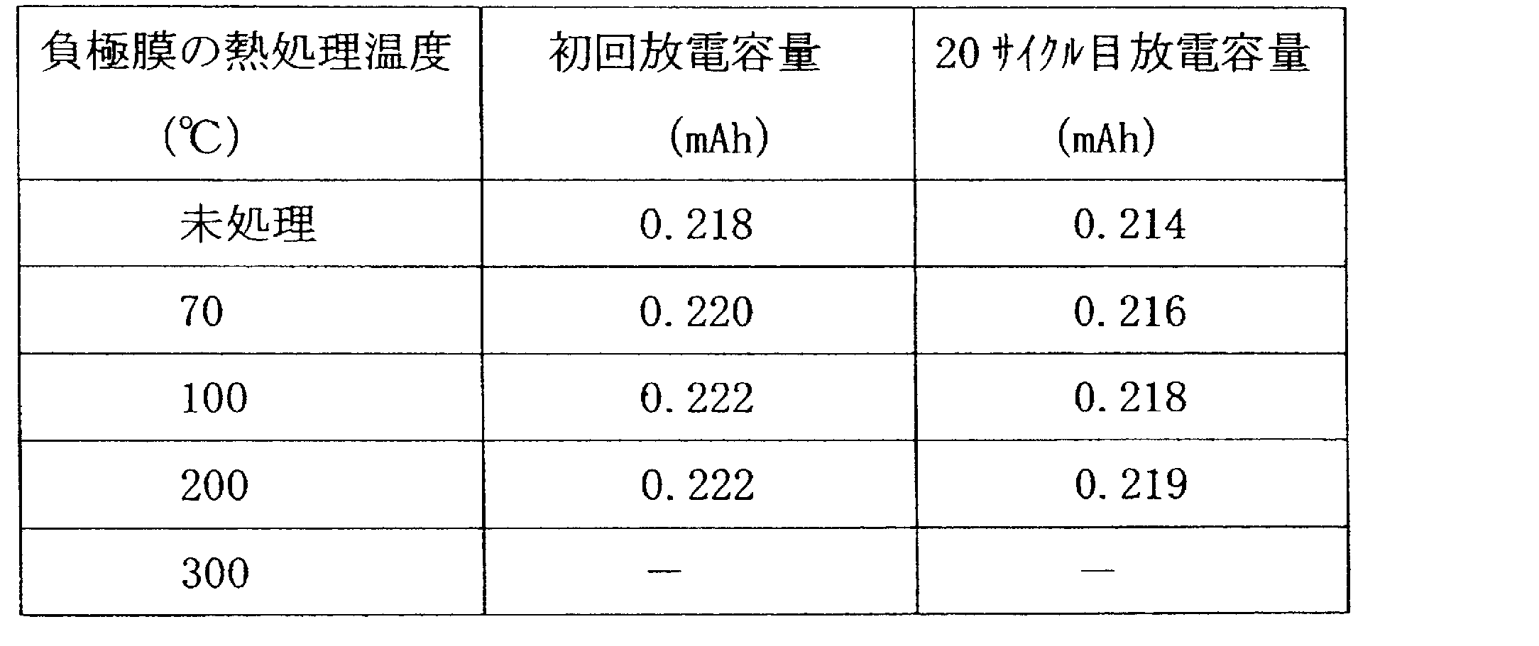
表3に示すように、熱処理を行うことで電池性能が向上した。なお、300℃では透明フィルム基板5が変形してしまい電池を作製することができなかった。
正極膜1について同様の実験を行った結果を表4に示す。

表4に示すように、正極膜1についても同様の熱処理を行うことで、負極膜3と同様の結果が得られた。
表3と表4に示す結果から、電極膜を成膜した後に70℃~200℃の温度範囲内の何れかの温度で3時間熱処理を行うと電池性能が向上することが分かった。よって、電極膜を成膜した後に熱処理を行うとよい。
本実施形態に係るリチウム二次電池100の製造方法は、フレキシブルな透明フィルム基板の上に形成されたリチウムイオンの挿入及び脱離が可能な物質を含む正極膜を成膜する正極成膜ステップと、リチウムイオン導電性を有する透明な電解質を形成する電解質形成ステップと、フレキシブルな透明フィルム基板の上に形成されたリチウムの溶解及び析出又はリチウムイオンの挿入及び脱離が可能な物質で形成される負極膜を成膜する負極成膜ステップとを含むリチウム二次電池の製造方法であって、正極成膜ステップ及び負極成膜ステップは、電極膜の成膜後にアルゴン雰囲気中で70~200℃の温度範囲内の何れかの温度で3時間熱処理を行う。これによりリチウム二次電池100の性能を向上させることができる。
(電極膜表面の表面粗さについて)
可視光に対する透過性を有するリチウム二次電池100を実現する場合、電極膜の表面粗さが光の透過率に大きく影響する。つまり、他の構成要素である透明フィルム基板4、電解質2、及びラミネートフィルム7は基本的に光を通すのに対して正極膜1と負極膜3はそうでないからである。よって、正極膜1及び負極膜3の電極膜表面の表面粗さが粗いと光が乱反射され透過率が低下すると考えられる。
可視光に対する透過性を有するリチウム二次電池100を実現する場合、電極膜の表面粗さが光の透過率に大きく影響する。つまり、他の構成要素である透明フィルム基板4、電解質2、及びラミネートフィルム7は基本的に光を通すのに対して正極膜1と負極膜3はそうでないからである。よって、正極膜1及び負極膜3の電極膜表面の表面粗さが粗いと光が乱反射され透過率が低下すると考えられる。
そこで、負極膜3と正極膜1の表面粗さと光の透過率との関係について実験を行った。
表面粗さは、原子間力顕微鏡(日立ハイテクノロジー社製AFM5200S)で500×500nmの表面を計測して行った。実験結果を表4に示す。
表5に示す比較例1は、上記の実施例で作製された正極膜1と負極膜3の表面に傷を付けたものである。傷は、電極膜を固定した基板を10rpmで回転させ、直径が約0.2mmのタイロン樹脂性の毛先を持つブラシを電極膜の表面に接触させて生じさせた。

表5に示すように、電極膜の成膜後に熱処理を行うことで電極膜の表面が平滑化されることが分かる。表面粗さが小さくなるに従って光の透過率も向上する。
表5に示す結果から、熱処理が無くても、負極膜3の表面粗さを60nm以下、正極膜の表面粗さを80nm以下にすれば20%以上の透過率が得られることが分かる。
(柔軟性)
本実施形態に係るリチウム二次電池100の柔軟性について検討した。
本実施形態に係るリチウム二次電池100の柔軟性について検討した。
柔軟性は、リチウム二次電池100の両端部を支点に、電池の中央部分に鉛直下方に荷重し、電池のたわみ量と荷重の関係で評価した。
図6は、柔軟性を評価する様子を模式的に示す図である。図5(a)は平面図、図5(b)は側面図である。高さが15mmの金属支柱20を30mmの間隔を空けて設置し、金属支柱20の上にリチウム二次電池100(電池)を掛け渡し、電池の中心に重さ200g、直径10mmの金属棒30を置き、電池の裏面が金属支柱20を設置した平面に接触するまで金属棒30に荷重した重さを柔軟性の指標とした。
ラミネートフィルム7の厚さが50μm(電池の厚み421μm)、100μm(電池の厚み523μm)、150μm(電池の厚み625μm)である電池を作製し、柔軟性を評価した。評価した結果を表6に示す。表6に示す荷重量の内の200gは金属棒30の重量である。

表6に示すように、電池の厚さが増すにしたがって電池を一定量撓ます為の荷重量は大きくなる。このように電池の厚さが増せば柔軟性は損なわれる。
ウェアラブル機器に、本実施形態に係るリチウム二次電池100を搭載することを想定した場合、電池の柔軟性は、例えば500gの荷重で上記の撓み量分たわめば十分だと考えられる。よって、リチウム二次電池100の厚さは500μm以下であることが望ましい。
リチウム二次電池100の厚さを500μm以下にすれば、光の透過性に加えて実用上十分な柔軟性も備えることができる。
(比較例2)
上記の実施例及び実験例と比較する目的で、導電助剤であるカーボンを電極膜に混合させた比較例2のリチウム二次電池を作製した。
上記の実施例及び実験例と比較する目的で、導電助剤であるカーボンを電極膜に混合させた比較例2のリチウム二次電池を作製した。
比較例2のリチウム二次電池は、膜厚が80nmのコバルト酸リチウム(LiCoO2)の正極膜1及びチタン酸リチウム(Li4Ti5O12)の負極膜3のそれぞれの上に、膜厚20nmのカーボン薄膜を成膜して作製した。これ以外の構成は上記の実施例と同じとした。
図7は、比較例2の光透過特性を示す図である。図7の横軸は光の波長[nm]、縦軸は光の透過率[%]である。図7において、破線は負極膜3を含む透明フィルム基板5の光の透過特性を示す。一点鎖線は正極膜1を含むフィルム板4の光透過特性を示す。実線は比較例2の電池全体の光透過特性を示す。
図7に示すように比較例2の電池全体の透過率は5%以下でありほとんど光を透過しない。また、破線で示す負極膜3の透過率は、上記の実施例(図5)の半分以下である。このように比較例2の透過率が低い理由は、カーボン薄膜における光の反射及び吸収が多いためだと考えられる。
比較例2(図7)と本実施形態に係るリチウム二次電池100(図5)を比較することで、本実施形態の光の透過特性が優れていることが良く分かる。
このように本発明によれば、可視光に対する透過性と柔軟性を兼ね備えたリチウム二次電池とその製造方法を提供することができる。なお、本発明は、上記の実施形態に限定されるものではなく、その要旨の範囲内で変形が可能である。
本実施の形態は、可視光透過性と柔軟性を兼ね備えてリチウム二次電池を作製することができ、様々な電子機器の電源として利用可能である。
1:正極膜
2:電解質
3:負極膜
4,5:透明フィルム基板
6:透明電極膜
7:ラミネートフィルム
8:正極端子
9:負極端子
100:リチウム二次電池
2:電解質
3:負極膜
4,5:透明フィルム基板
6:透明電極膜
7:ラミネートフィルム
8:正極端子
9:負極端子
100:リチウム二次電池
Claims (5)
- フレキシブルな透明フィルム基板の上に形成されたリチウムイオンの挿入及び脱離が可能な物質を含む正極膜と、
リチウムイオン導電性を有する透明な電解質と、
フレキシブルな透明フィルム基板の上に形成されたリチウムの溶解及び析出又はリチウムイオンの挿入及び脱離が可能な物質で形成される負極膜と
を備えることを特徴とするリチウム二次電池。 - 前記正極膜にリチウム源が含有されている場合は、
負極材料に、スズ酸化物、ケイ素酸化物、チタン酸化物、タングステン酸化物、ニオブ酸化物、モリブデン酸化物、金属リン化物、金属硫化物、金属窒化物、金属フッ化物、及び金属チタン複合酸化物の何れかを用いて前記負極膜を50~300nmの膜厚にする
ことを特徴とする請求項1に記載のリチウム二次電池。 - 前記負極膜にリチウム源が含有されている場合は、
正極材料に、マンガン酸化物、鉄酸化物、銅酸化物、ニッケル酸化物、バナジウム酸化物、金属硫化物、金属硫酸塩化合物、金属リン酸塩化合物、金属フッ化物、金属モリブデン複合酸化物、金属タングステン複合酸化物、及び金属シアノ錯体の何れかを用いて前記正極膜を50~300nmの膜厚にする
ことを特徴とする請求項1に記載のリチウム二次電池。 - 前記正極膜の表面粗さは60nm以下であり、
前記負極膜の表面粗さは80nm以下である
ことを特徴とする請求項1乃至3の何れかに記載のリチウム二次電池。 - フレキシブルな透明フィルム基板の上に形成されたリチウムイオンの挿入及び脱離が可能な物質を含む正極膜を成膜する正極成膜ステップと、リチウムイオン導電性を有する透明な電解質を形成する電解質形成ステップと、フレキシブルな透明フィルム基板の上に形成されたリチウムの溶解及び析出又はリチウムイオンの挿入及び脱離が可能な物質で形成される負極膜を成膜する負極成膜ステップとを含むリチウム二次電池の製造方法であって、
前記正極成膜ステップ及び前記負極成膜ステップは、電極膜の成膜後にアルゴン雰囲気中で70~200℃の熱処理を行う
ことを特徴とするリチウム二次電池の製造方法。
Priority Applications (1)
| Application Number | Priority Date | Filing Date | Title |
|---|---|---|---|
| US17/288,439 US20210399295A1 (en) | 2018-11-20 | 2019-11-06 | Lithium Secondary Battery and Manufacturing Method Thereof |
Applications Claiming Priority (2)
| Application Number | Priority Date | Filing Date | Title |
|---|---|---|---|
| JP2018217084A JP2020087584A (ja) | 2018-11-20 | 2018-11-20 | リチウム二次電池とその製造方法 |
| JP2018-217084 | 2018-11-20 |
Publications (1)
| Publication Number | Publication Date |
|---|---|
| WO2020105439A1 true WO2020105439A1 (ja) | 2020-05-28 |
Family
ID=70774526
Family Applications (1)
| Application Number | Title | Priority Date | Filing Date |
|---|---|---|---|
| PCT/JP2019/043533 WO2020105439A1 (ja) | 2018-11-20 | 2019-11-06 | リチウム二次電池とその製造方法 |
Country Status (3)
| Country | Link |
|---|---|
| US (1) | US20210399295A1 (ja) |
| JP (1) | JP2020087584A (ja) |
| WO (1) | WO2020105439A1 (ja) |
Cited By (2)
| Publication number | Priority date | Publication date | Assignee | Title |
|---|---|---|---|---|
| WO2022254524A1 (ja) * | 2021-05-31 | 2022-12-08 | 日本電信電話株式会社 | リチウム二次電池とその製造方法 |
| CN116722129A (zh) * | 2023-08-09 | 2023-09-08 | 泰鼎新能源(浙江)有限公司 | 一种高性能硅氧负极材料及其制备方法与应用 |
Families Citing this family (3)
| Publication number | Priority date | Publication date | Assignee | Title |
|---|---|---|---|---|
| JP7481648B2 (ja) * | 2020-06-02 | 2024-05-13 | 日本電信電話株式会社 | リチウム二次電池 |
| WO2023105573A1 (ja) * | 2021-12-06 | 2023-06-15 | 日本電信電話株式会社 | リチウム二次電池、及び、リチウム二次電池の製造方法 |
| WO2023238379A1 (ja) * | 2022-06-10 | 2023-12-14 | 日本電信電話株式会社 | リチウム二次電池、及び、リチウム二次電池の製造方法 |
Citations (5)
| Publication number | Priority date | Publication date | Assignee | Title |
|---|---|---|---|---|
| JPH04337247A (ja) * | 1991-05-14 | 1992-11-25 | Asahi Chem Ind Co Ltd | 非水系二次電池 |
| JP2006216336A (ja) * | 2005-02-02 | 2006-08-17 | Geomatec Co Ltd | 薄膜固体二次電池 |
| KR20140006573A (ko) * | 2012-07-06 | 2014-01-16 | 한국전기연구원 | 유연성 투명 전지의 제조 방법 |
| US20150277498A1 (en) * | 2014-04-01 | 2015-10-01 | Tianjin Funayuanchuang Technology Co.,Ltd. | Flexible electronic device |
| WO2017056326A1 (ja) * | 2015-10-02 | 2017-04-06 | 学校法人工学院大学 | リチウムイオン二次電池 |
Family Cites Families (2)
| Publication number | Priority date | Publication date | Assignee | Title |
|---|---|---|---|---|
| JP2004311108A (ja) * | 2003-04-03 | 2004-11-04 | Nissan Motor Co Ltd | 全固体高分子電池及び製造方法 |
| WO2018044129A1 (ko) * | 2016-09-02 | 2018-03-08 | 주식회사 엘지화학 | 젤 폴리머 전해질 및 이를 포함하는 리튬 이차전지 |
-
2018
- 2018-11-20 JP JP2018217084A patent/JP2020087584A/ja active Pending
-
2019
- 2019-11-06 WO PCT/JP2019/043533 patent/WO2020105439A1/ja active Application Filing
- 2019-11-06 US US17/288,439 patent/US20210399295A1/en active Pending
Patent Citations (5)
| Publication number | Priority date | Publication date | Assignee | Title |
|---|---|---|---|---|
| JPH04337247A (ja) * | 1991-05-14 | 1992-11-25 | Asahi Chem Ind Co Ltd | 非水系二次電池 |
| JP2006216336A (ja) * | 2005-02-02 | 2006-08-17 | Geomatec Co Ltd | 薄膜固体二次電池 |
| KR20140006573A (ko) * | 2012-07-06 | 2014-01-16 | 한국전기연구원 | 유연성 투명 전지의 제조 방법 |
| US20150277498A1 (en) * | 2014-04-01 | 2015-10-01 | Tianjin Funayuanchuang Technology Co.,Ltd. | Flexible electronic device |
| WO2017056326A1 (ja) * | 2015-10-02 | 2017-04-06 | 学校法人工学院大学 | リチウムイオン二次電池 |
Non-Patent Citations (1)
| Title |
|---|
| MUROTANI, HIROSHI: "Influence of the Surface-roughness of the Substrate on the Light Scattering of Optical Thin Films", JOURNAL OF THE JAPAN SOCIETY FOR PRECISION ENGINEERING, vol. 80, no. 6, 5 June 2014 (2014-06-05), pages 519 - 523 * |
Cited By (3)
| Publication number | Priority date | Publication date | Assignee | Title |
|---|---|---|---|---|
| WO2022254524A1 (ja) * | 2021-05-31 | 2022-12-08 | 日本電信電話株式会社 | リチウム二次電池とその製造方法 |
| CN116722129A (zh) * | 2023-08-09 | 2023-09-08 | 泰鼎新能源(浙江)有限公司 | 一种高性能硅氧负极材料及其制备方法与应用 |
| CN116722129B (zh) * | 2023-08-09 | 2023-11-03 | 泰鼎新能源(浙江)有限公司 | 一种高性能硅氧负极材料及其制备方法与应用 |
Also Published As
| Publication number | Publication date |
|---|---|
| US20210399295A1 (en) | 2021-12-23 |
| JP2020087584A (ja) | 2020-06-04 |
Similar Documents
| Publication | Publication Date | Title |
|---|---|---|
| WO2020105439A1 (ja) | リチウム二次電池とその製造方法 | |
| US9412988B2 (en) | Separator including coating layer of inorganic and organic mixture, and battery including the same | |
| WO2015068268A1 (ja) | 全固体電池、全固体電池用電極及びその製造方法 | |
| CN102668190B (zh) | 固体电解质电池和正极活性物质 | |
| JP5413129B2 (ja) | 固体電池の製造方法 | |
| WO2017046917A1 (ja) | 二次電池用複合電解質、二次電池及び電池パック | |
| US20200280102A1 (en) | All-solid-state battery and method for manufacturing the same | |
| MX2013013478A (es) | Material activo de electrodos negativos para dispositivo electrico. | |
| CN110416630B (zh) | 全固体电池 | |
| WO2020105431A1 (ja) | ナトリウム二次電池とその製造方法 | |
| CA3079064C (en) | Solid-state thin film hybrid electrochemical cell | |
| JP4381176B2 (ja) | 薄膜固体二次電池 | |
| US20220359912A1 (en) | Composite solid-state battery cell | |
| JP6730584B2 (ja) | 全固体電池、及び全固体電池の製造方法 | |
| JP6748348B2 (ja) | 全固体電池 | |
| JP2019533277A (ja) | リチウムイオン電池の新規なケイ素/グラフェン・アノード用の導電性ポリマーバインダー | |
| KR20220144605A (ko) | 실리콘계 음극 및 이의 제조방법 | |
| JP2013026187A (ja) | 蓄電デバイス用負極材料とその製造方法 | |
| KR20210088257A (ko) | 테이핑 영역을 포함하는 전극 집전체용 금속 박막 및 이를 이용한 전극 제조방법 | |
| JP6697155B2 (ja) | 全固体電池 | |
| WO2023238379A1 (ja) | リチウム二次電池、及び、リチウム二次電池の製造方法 | |
| WO2021111497A1 (ja) | カリウム二次電池とその製造方法 | |
| CN113078285B (zh) | 一种柔性电池 | |
| KR101918112B1 (ko) | 리튬 전지 및 그 제조방법 | |
| WO2022254524A1 (ja) | リチウム二次電池とその製造方法 |
Legal Events
| Date | Code | Title | Description |
|---|---|---|---|
| 121 | Ep: the epo has been informed by wipo that ep was designated in this application |
Ref document number: 19887672 Country of ref document: EP Kind code of ref document: A1 |
|
| NENP | Non-entry into the national phase |
Ref country code: DE |
|
| 122 | Ep: pct application non-entry in european phase |
Ref document number: 19887672 Country of ref document: EP Kind code of ref document: A1 |