WO2020105387A1 - コネクタ、及びコネクタを備えるワイヤハーネス - Google Patents
コネクタ、及びコネクタを備えるワイヤハーネスInfo
- Publication number
- WO2020105387A1 WO2020105387A1 PCT/JP2019/042711 JP2019042711W WO2020105387A1 WO 2020105387 A1 WO2020105387 A1 WO 2020105387A1 JP 2019042711 W JP2019042711 W JP 2019042711W WO 2020105387 A1 WO2020105387 A1 WO 2020105387A1
- Authority
- WO
- WIPO (PCT)
- Prior art keywords
- connector
- wire
- height direction
- terminal
- electric wire
- Prior art date
- Legal status (The legal status is an assumption and is not a legal conclusion. Google has not performed a legal analysis and makes no representation as to the accuracy of the status listed.)
- Ceased
Links
Images



Classifications
-
- H—ELECTRICITY
- H01—ELECTRIC ELEMENTS
- H01R—ELECTRICALLY-CONDUCTIVE CONNECTIONS; STRUCTURAL ASSOCIATIONS OF A PLURALITY OF MUTUALLY-INSULATED ELECTRICAL CONNECTING ELEMENTS; COUPLING DEVICES; CURRENT COLLECTORS
- H01R13/00—Details of coupling devices of the kinds covered by groups H01R12/70 or H01R24/00 - H01R33/00
- H01R13/46—Bases; Cases
- H01R13/52—Dustproof, splashproof, drip-proof, waterproof, or flameproof cases
- H01R13/5205—Sealing means between cable and housing, e.g. grommet
-
- H—ELECTRICITY
- H01—ELECTRIC ELEMENTS
- H01R—ELECTRICALLY-CONDUCTIVE CONNECTIONS; STRUCTURAL ASSOCIATIONS OF A PLURALITY OF MUTUALLY-INSULATED ELECTRICAL CONNECTING ELEMENTS; COUPLING DEVICES; CURRENT COLLECTORS
- H01R13/00—Details of coupling devices of the kinds covered by groups H01R12/70 or H01R24/00 - H01R33/00
- H01R13/46—Bases; Cases
- H01R13/52—Dustproof, splashproof, drip-proof, waterproof, or flameproof cases
- H01R13/5219—Sealing means between coupling parts, e.g. interfacial seal
- H01R13/5221—Sealing means between coupling parts, e.g. interfacial seal having cable sealing means
-
- H—ELECTRICITY
- H01—ELECTRIC ELEMENTS
- H01B—CABLES; CONDUCTORS; INSULATORS; SELECTION OF MATERIALS FOR THEIR CONDUCTIVE, INSULATING OR DIELECTRIC PROPERTIES
- H01B7/00—Insulated conductors or cables characterised by their form
- H01B7/0045—Cable-harnesses
-
- H—ELECTRICITY
- H01—ELECTRIC ELEMENTS
- H01R—ELECTRICALLY-CONDUCTIVE CONNECTIONS; STRUCTURAL ASSOCIATIONS OF A PLURALITY OF MUTUALLY-INSULATED ELECTRICAL CONNECTING ELEMENTS; COUPLING DEVICES; CURRENT COLLECTORS
- H01R13/00—Details of coupling devices of the kinds covered by groups H01R12/70 or H01R24/00 - H01R33/00
- H01R13/02—Contact members
- H01R13/22—Contacts for co-operating by abutting
- H01R13/24—Contacts for co-operating by abutting resilient; resiliently-mounted
- H01R13/2407—Contacts for co-operating by abutting resilient; resiliently-mounted characterized by the resilient means
-
- H—ELECTRICITY
- H01—ELECTRIC ELEMENTS
- H01R—ELECTRICALLY-CONDUCTIVE CONNECTIONS; STRUCTURAL ASSOCIATIONS OF A PLURALITY OF MUTUALLY-INSULATED ELECTRICAL CONNECTING ELEMENTS; COUPLING DEVICES; CURRENT COLLECTORS
- H01R2201/00—Connectors or connections adapted for particular applications
- H01R2201/26—Connectors or connections adapted for particular applications for vehicles
Definitions
- the present invention relates to a connector and a wire harness with a connector.
- an electric wire insertion portion that is opened in a direction orthogonal to the height direction and a part of the electric wire member is inserted, and a terminal member of a mating connector that is opened in the height direction can be inserted
- an L-shaped tubular connector provided with a connector opening for electrically connecting the terminal member to the electric wire member
- the present invention has been made to solve the above problems, and an object thereof is to provide a connector and a wire harness with a connector that can be made thinner.
- a connector that solves the above problem is a connector that is fitted in a height direction with a mating connector, and an electric wire insertion portion that is opened in a direction orthogonal to the height direction and into which a part of an electric wire member is inserted, A connector opening that opens in the height direction and into which the terminal member of the mating connector can be inserted so that the terminal member can be electrically connected to the electric wire member, and a connector fitting that is fitted to the mating connector And a sealing portion between the connector fitting portion and the mating connector within a range of the electric wire seal member for sealing between the electric wire member and the electric wire insertion portion. It is set so that at least a part of the connector seal member in the height direction overlaps.
- the connector for sealing between the connector fitting portion and the mating connector is within the range in the height direction of the electric wire sealing member for sealing between the electric wire member and the electric wire insertion portion. Since the ranges of the sealing member in the height direction overlap at least partially, the height of the connector can be reduced, and the connector can be thinned.
- a wire harness with a connector that solves the above problems includes the connector and an electric wire member. According to this configuration, in the wire harness with a connector, the height of the connector can be reduced, and the wire harness with a connector can be made thin.
- the wire harness with a connector wherein the range in the height direction of the connector sealing member is set to overlap at least partially within the range in the height direction of the wire member inserted in the wire insertion portion.
- the range in the height direction of the connector sealing member is set to overlap at least partially within the range in the height direction of the wire member inserted in the wire insertion portion.
- the connector seal member since the range in the height direction of the connector seal member is set to at least partially overlap with the range in the height direction of the wire member inserted in the wire insertion portion, the connector is formed.
- the height of the wire harness can be reduced, and the wire harness with a connector can be thinned.
- the above-described wire harness with a connector comprising a connector terminal disposed at the back of the connector opening portion, to which the electric wire member is electrically connected, and a terminal member of the mating connector is in contact, the connector terminal comprising: It is preferable that the connector terminals are formed in a flat plate shape and arranged so that the plate thickness direction of the connector terminals coincides with the height direction.
- the connector terminal is formed in a flat plate shape and arranged so that the plate thickness direction of the connector terminal coincides with the height direction, so that the height of the connector terminal is ensured while ensuring the cross-sectional area of the connector terminal. Can be lowered, and the wire harness with a connector can be made thinner.
- the cross-sectional area of the connector terminal is the area of the cut surface of the connector terminal cut by the surface orthogonal to the direction of the current flowing through the connector terminal.
- the minimum cross-sectional area of the connector terminal is determined according to the amount of current flowing so that abnormal heat generation does not occur. If the minimum cross-sectional area is not taken into consideration, it is possible to reduce the height of the connector simply by using the connector terminal as a thin wire or the like. On the other hand, in the above configuration, it is possible to reduce the height of the connector while ensuring the minimum cross-sectional area that does not cause abnormal heat generation of the connector terminal, and to make the wire harness with a connector thin. You can
- the wire harness with a connector wherein the electric wire member includes an electric wire having a core wire and an insulating coating covering an outer periphery of the core wire, wherein the connector terminal is from the connector opening portion in the height direction of the core wire. It is preferably connected to the core wire on the far side.
- the connector terminal is connected to the core wire on the side far from the connector opening in the height direction of the core wire of the electric wire member, so that a wider space can be secured on the connector fitting portion side than the connector terminal.
- the connector seal member can be brought closer to the center side of the electric wire seal member in the height direction of the electric wire seal member. That is, it becomes easier to overlap the range of the electric wire seal member in the height direction and the range of the connector seal member in the height direction. Therefore, the connector can be made thinner.
- the core wire is in surface contact with a circular cross-section portion arranged inside the electric wire insertion portion and the flat-plate-shaped connector terminal formed on the tip end side of the circular cross-section portion. It is preferable that the crushed portion is formed so as to be flush with the surface of the circular cross-section portion on the side far from the connector opening in the height direction.
- the crushed portion of the core wire is formed so as to be flush with the surface of the circular cross-section portion on the side far from the connector opening in the height direction. It is possible to secure a wider space. Therefore, the connector seal member can be brought closer to the center side of the electric wire seal member in the height direction of the electric wire seal member. That is, it becomes easier to overlap the range of the electric wire seal member in the height direction and the range of the connector seal member in the height direction. Therefore, the connector can be made thinner.
- the connector and the wire harness with a connector of the present invention it is possible to reduce the thickness.
- the wire harness with a connector of one embodiment, and a one part disassembled perspective view of the other party connector Sectional drawing of the wire harness with a connector of one embodiment, and the other party connector.
- FIGS. 1 to 3 an embodiment of a wire harness with a connector will be described with reference to FIGS. 1 to 3.
- a part of the configuration may be exaggerated or simplified.
- the dimensional ratio of each part may be different from the actual one.
- the wire harness 10 with a connector includes a connector 11 and an electric wire member 12.
- the connector-equipped wire harness 10 is, for example, fitted in a height direction with a mating connector 13 fixed to an electric device such as an inverter (not shown).
- the height directions described in the present embodiment are all the directions that coincide with the direction in which the connector-equipped wire harness 10 is fitted into the mating connector 13. Further, the vertical direction in FIGS. 1 to 3 corresponds to the height direction described in the present embodiment.
- the connector 11 includes a connector main body 14, a first cover Ca provided so as to cover the outer surface of the connector main body 14, and a second cover Cb.
- the connector body 14 is opened in the direction orthogonal to the height direction of the connector 11 (vertical direction in FIG. 2) (in the illustrated example, the longitudinal direction of the electric wire member 12 or the longitudinal direction of the connector terminal 34 described later).
- the electric wire insertion portion 15 having, for example, a substantially rectangular tube shape into which the tip end of the electric wire is inserted.
- the electric wire insertion portion 15 of the present embodiment is provided in pairs at the same height in parallel.
- the connector body 14 includes a tubular communication portion 16 that communicates with the pair of electric wire insertion portions 15 and extends to the side opposite to the insertion side of the electric wire member 12.
- the communication portion 16 is formed on the upper side in the height direction of the wire insertion portion 15 (the upper side in the vertical direction in FIG. 2).
- the lower surface of the lower wall of the communication portion 16 is formed at a substantially central position in the height direction of the wire insertion portion 15.
- the connector body 14 includes a connector terminal support wall 17 extending from an upper wall of the communication portion 16, a lower wall of the communication portion 16 and a peripheral portion of the connector terminal support wall 17 and a lower side in a height direction (see FIG. 2).
- the connecting tube portion 18 has a substantially rectangular tube shape and extends in the middle and lower side in the vertical direction.
- the inner surface of the connecting tubular portion 18 is opened in the height direction (vertical direction in FIG. 2) so that the terminal member 19 of the mating connector 13 can be inserted and the terminal member 19 is electrically connected to the electric wire member 12. It is a connector opening 20 that enables it.
- the outer surface of the connecting tubular portion 18 is a connector fitting portion 22 into which the mating fitting portion 21 having a substantially rectangular tubular shape provided on the mating connector 13 is fitted. Specifically, in the connector fitting portion 22, a seal is provided between the connector fitting portion 22 and the mating fitting portion 21 of the mating connector 13 on the base end side (upper side in FIG. 2) of the connector fitting portion 22.
- a connector seal member 23 is provided for this purpose.
- the connector seal member 23 is made of an elastic member such as a rubber material.
- the connector seal member 23 is formed in a substantially rectangular tube shape, is externally fitted to the base end side of the connector fitting portion 22, and is fitted to the tip end side (lower side in FIG. 2) of the connector fitting portion 22. It is held by the retainer 24. Then, in the connector 11, the connector fitting portion 22 is fitted to the mating fitting portion 21 so that the connector sealing member 23 makes pressure contact with the inner surface of the mating fitting portion 21 of the mating connector 13. It is connected and fixed to the connector 13.
- the electric wire member 12 is an electric wire 33 having a core wire 31 that is a conductor and an insulating coating 32 that covers the outer periphery of the core wire 31.
- the core wire 31 of the electric wire member 12 is arranged behind the connector opening 20 (upper side in FIG. 2) and is supported by the lower surface of the connector terminal support wall 17 so that the mating connector 13 of the mating connector 13 can be supported.
- the connector terminal 34 with which the terminal member 19 contacts is electrically connected.
- the connector terminal 34 is formed in a flat plate shape, and is arranged so that the plate thickness direction of the connector terminal 34 coincides with the height direction (vertical direction in FIG. 2).
- the core wire 31 is formed at a circular section 31a arranged inside the open end of the electric wire inserting section 15 and at a portion of the tip end side of the circular section 31a which is exposed from the insulating coating 32 to the outside.
- a crushed portion 31b crushed so as to come into surface contact with the flat connector terminal 34 That is, the crushed portion 31b has a flat surface that can be in surface contact with the flat plate-shaped connector terminal 34.
- the connector terminal 34 becomes the crushed portion 31b on the side farther from the connector opening 20 (that is, the upper side in FIG. 2) in the height direction (vertical direction in FIG. 2) of the crushed portion 31b in the core wire 31 of the electric wire member 12. Connected and fixed by resistance welding.
- the electric wire member 12 is provided with an electric wire seal member 35 for sealing between the electric wire member 12 and the electric wire insertion portion 15.
- the electric wire seal member 35 is made of an elastic member such as a rubber material.
- the electric wire seal member 35 has a circular inner surface and a substantially square outer surface.
- the wire seal member 35 is externally fitted and fixed in advance at a position corresponding to the wire insertion portion 15 of the wire member 12.
- a seal retainer 36 is externally fitted and fixed to the electric wire member 12 at a position corresponding to the open end of the electric wire insertion portion 15. The tip end of the wire member 12 is inserted into the wire insertion portion 15 so that the connector terminal 34 fixed in advance as described above is supported on the lower surface of the connector terminal support wall 17.
- the electric wire member 12 is inserted into the electric wire insertion portion 15 at the tip side so that the electric wire seal member 35 is press-fitted into the electric wire insertion portion 15. Further, the electric wire member 12 is inserted into the electric wire inserting portion 15 at the tip side so that the seal retainer 36 is fixed inside the open end of the electric wire inserting portion 15.
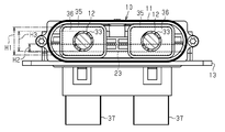
- the height range H2 of the connector seal member 23 is set to overlap the height range H1 of the wire seal member 35. ing. Further, in this embodiment, the height range H2 of the connector seal member 23 is set to overlap the height range H3 of the wire member 12 inserted into the wire insertion portion 15. That is, in the present embodiment, by providing the communication portion 16 on the upper side in the height direction of the wire insertion portion 15, the connecting tubular portion 18 extending downward from the communication portion 16 is located at a position overlapping the wire insertion portion 15 in the height direction. A connector seal member 23 is provided on the connector fitting portion 22 of the connecting tubular portion 18.
- the height range H2 of the connector seal member 23 is overlapped with the height range H1 of the wire seal member 35. Further, the height range H2 of the connector sealing member 23 is overlapped with the height range H3 of the wire member 12 inserted into the wire insertion portion 15.
- the terminal member 19 of the mating connector 13 is provided with a terminal 37 bent in an L shape so as to face the connector terminal 34, and a coil terminal 38 arranged on the upper surface of the terminal 37. ..
- the connector 11 is lowered by moving the connector 11 from above the mating connector 13 and fitting the connector fitting portion 22 to the mating fitting portion 21 via the connector seal member 23. It is connected and fixed to the mating connector 13. In the connected and fixed state, the coil terminal 38 is sandwiched between the terminal 37 and the connector terminal 34 and is elastically deformed and pressed against each other, so that the terminal 37 and the connector terminal 34, and by extension, the core wire 31 of the wire member 12. Are electrically connected.
- the connector terminal 34 Since the connector terminal 34 is formed in a flat plate shape and arranged so that the plate thickness direction of the connector terminal 34 coincides with the height direction (vertical direction in FIG. 2), the cross-sectional area of the connector terminal 34 is reduced. The height of the connector 11 can be reduced while ensuring the thickness, and the connector 11 and the wire harness 10 with a connector can be thinned.
- the cross-sectional area of the connector terminal 34 is the area of the cut surface of the connector terminal 34, which is cut by the surface orthogonal to the direction of the current flowing through the connector terminal 34. The minimum cross-sectional area of the connector terminal 34 at which abnormal heat generation or the like does not occur is determined according to the amount of current flowing.
- the height of the connector 11 can be reduced by simply using the connector terminal 34 as a thin wire or the like.
- the height of the connector 11 can be reduced while ensuring the minimum cross-sectional area where abnormal heat generation of the connector terminal 34 does not occur, and the connector 11 and the wire harness 10 with a connector are provided. Can be made thinner.
- the connector terminal 34 is electrically connected via the terminal 37 and the coil terminal 38 which face each other, when the connector terminal 34 and the terminal 37 are a male terminal and a female terminal to be inserted / removed in the height direction, respectively. Compared with, there is no need to insert a terminal in the height direction. Therefore, it is possible to reduce the thickness of the connector 11 and the wire harness 10 with a connector.
- the connector terminal 34 is connected to the core wire 31 on the side farther from the connector opening 20 (that is, the upper side in FIG. 2) in the height direction (vertical direction in FIG. 2) of the crushed portion 31b of the core wire 31 of the electric wire member 12. Connected. Therefore, it is possible to secure a wider space on the connector fitting portion 22 side than the connector terminal 34. Therefore, the connector seal member 23 can be brought closer to the center side of the electric wire seal member 35 in the height direction of the electric wire seal member 35. That is, the range H1 in the height direction of the wire seal member 35 and the range H2 in the height direction of the connector seal member 23 can be more easily overlapped. Therefore, the connector 11 and the wire harness 10 with a connector can be made thinner.
- This embodiment can be modified and implemented as follows.
- the present embodiment and the following modified examples can be implemented in combination with each other within a technically consistent range.
- the crushing part 31b (refer FIG. 2) of the core wire 31 was formed in the center of the cross-section circular part 31a in the height direction, it is not limited to this, and it may be formed in another position. Good.
- the crushed portion 31c has a surface (in FIG. 4) on the side far from the connector opening 20 (see FIG. 2) in the height direction (vertical direction in FIG. 4) of the circular section 31a. , The upper surface).
- the connector seal member 23 can be brought closer to the center side of the electric wire seal member 35 in the height direction of the electric wire seal member 35. That is, the range H1 in the height direction of the wire seal member 35 and the range H2 in the height direction of the connector seal member 23 can be more easily overlapped. Therefore, the connector 11 and the wire harness 10 with a connector can be made thinner.
- the crushed portion 31b may have a shape in which the surface closer to the connector opening 20 is closer to the side farther from the connector opening 20 than the central axis in the height direction of the core wire 31, for example.
- the height range H1 of the electric wire seal member 35 is set to be entirely overlapped with the height range H2 of the connector seal member 23.
- the present invention is not limited to this. You may set so that a part may overlap. Even in this case, it is possible to reduce the thickness of the connector 11 and the connector-equipped wire harness 10 as compared with those that do not overlap.
- the height range H3 of the connector seal member 23 is set to overlap the height range H3 of the wire member 12 inserted in the wire insertion portion 15.
- the present invention is not limited to this, and it may be set so as to partially overlap each other or may be set so as not to overlap at all.
- the connector terminal 34 is formed in a flat plate shape, and is arranged so that the plate thickness direction of the connector terminal 34 coincides with the height direction (vertical direction in FIG. 2).
- the plate thickness direction may be arranged so that the plate thickness direction does not coincide with the height direction, or may have a shape other than the flat plate shape.
- the connector terminal 34 is provided on the side farther from the connector opening 20 (that is, on the upper side in FIG. 2) in the height direction (vertical direction in FIG. 2) of the crushed portion 31b of the core wire 31 of the electric wire member 12.
- the present invention is not limited to this.
- the electric wire member 12 is the electric wire 33 having the core wire 31 and the insulating coating 32 covering the outer circumference of the core wire 31, but the present invention is not limited to this, and other configurations including the electric wire 33.
- an electric wire member including an electromagnetic shield member that covers the outer surface of the electric wire 33 may be used.
- the electric wire member 12 was two pieces, it is not limited to this, and it may be one piece and may be three or more pieces.
- the coil terminal 38 is provided on the terminal 37 side, but the coil terminal 38 may be provided on the connector terminal 34 side.
- the height direction in the above embodiment may be referred to as the insertion direction of the mating connector 13 into the connector 11.
- the direction orthogonal to the height direction in the above embodiment may be referred to as the insertion direction of the electric wire 12 into the connector 11.
- the insertion direction of the electric wire 12 into the connector 11 in the above embodiment may be the longitudinal direction of the electric wire 12 or the core wire 31.
- the insertion direction of the mating connector 13 into the connector 11 is orthogonal to the longitudinal direction of the electric wire 12 or the core wire 31.
- the insertion direction of the electric wire 12 into the connector 11 may be the first direction, the longitudinal direction of the connector 11, or the longitudinal direction of the wire harness 10.
- the mating connector 13 may be inserted into the connector 11 in a second direction orthogonal to the first direction, in the height direction of the connector 11, or in the height direction of the wire harness 10.
- the third direction orthogonal to the first direction and the second direction may be the depth direction of the connector 11 or the depth direction of the wire harness 10.
- the range H1 in the above embodiment may be referred to as the occupied range of the seal member 35 in the second direction when the connector 11 is viewed from the third direction.
- the range H1 of the above embodiment is the radial dimension of the seal member 35 in the second direction, the maximum dimension of the seal member 35 in the second direction when the connector 11 is viewed from the third direction, or the connector 11 in the third direction. It corresponds to the opening dimension of the wire insertion portion 15 in the second direction when viewed from above.
- the seal member 35 may have two radially outer surface portions of the seal member 35, which may be an upper side surface portion and a lower side surface portion of the seal member 35 and are separated from each other in the second direction. it can.
- the range H1 in the above embodiment can be defined by, for example, two radially outer surface portions of the seal member 35 that are separated from each other in the second direction.
- the range H2 in the above embodiment may be referred to as the occupied range of the connector seal member 23 in the second direction when the connector 11 is viewed from the third direction.
- the range H2 in the above embodiment corresponds to the axial dimension of the connector seal member 23 or the maximum dimension of the connector seal member 23 in the second direction when the connector 11 is viewed from the third direction.
- the connector seal member 23 can have two annular end faces that can be the upper end face and the lower end face of the connector seal member 23.
- the range H2 in the above embodiment can be defined by, for example, the upper end surface and the lower end surface of the connector seal member 23.
- the range H3 in the above embodiment may be referred to as the occupied range of the wire member 12 in the second direction when the connector 11 is viewed from the third direction.
- the range H3 of the above embodiment corresponds to the diameter of the electric wire member 12, the radial dimension of the electric wire member 12 in the second direction, or the maximum dimension of the electric wire member 12 in the second direction when the connector 11 is viewed from the third direction. To do.
- the electric wire member 12 can have the upper side surface or the uppermost position and the lower side surface or the lowermost position of the electric wire member 12 in the electric wire insertion portion 15.
- the range H3 of the above embodiment can be defined by, for example, the upper side surface and the lower side surface of the electric wire member 12 in the electric wire insertion portion 15.
- the connector 11 may be referred to as a flat connector or a low profile connector in which the height of the connector 11 is smaller than the depth of the connector 11.
- the height of the connector 11 may be smaller than the length of the connector 11.
- a connector (11) according to one or a plurality of mounting examples of the present disclosure includes a conductive core wire (31) of an electric wire member (12) of a wire harness (10) and a conductive terminal member of a mating connector (13). Is configured to electrically connect to (19), the connector (11) can include an insulative housing (14), the insulative housing (14) including a first opening (15).
- the first opening (15) has a distal end portion (31b) of the conductive core wire (31) inserted into the first opening (15) from a first direction which is a longitudinal direction of the conductive core wire (31). Is configured to receive loosely, The second opening (20) loosely receives the conductive terminal member (19) of the mating connector (13) inserted into the second opening (20) from a second direction orthogonal to the first direction. Is configured as With the first opening (15) loosely receiving the distal end portion (31b) of the conductive core wire (31), the first elastic closed loop seal member (35) serves as the first insulating connecting portion.
- the second elastic closed-loop seal member (23) has the second insulating property.
- the first elastic closed-loop seal member (35) has two radial outer surface portions of the first elastic closed-loop seal member (35) spaced from each other in the second direction, and The two radially outer surface portions of the elastic closed-loop seal member (35) define the occupation range (H1) of the first elastic closed-loop seal member (35) in the second direction
- the second elastic closed loop seal member (23) has a first annular end surface and a second annular end surface that are both end surfaces of the second elastic closed loop seal member (23), and the first annular The end surface and the second annular end surface define the occupied range (H2) of the second elastic closed loop seal member (23) in the second direction,
- the occupation range (H2) of the second elastic closed loop seal member (23) is the first The occupation range (H1) of the elastic closed loop seal member (35) can overlap in the second
- the first annular end surface of the second elastic closed-loop seal member (23) is arranged in the second direction of the first elastic closed-loop seal member (35) in a second direction. Located between two radially outer surface portions.
- first annular end surface and the second annular end surface of the second elastic closed-loop seal member (23) are the first elastic closed-loop seal member in a second direction. It is located between the two radially outer surface portions of (35).
- the mating connector (13) may include a connecting tubular portion (21) surrounding the conductive terminal member (19), and the second elastic closed loop seal.
- the member (23) can be attached to the outer side surface of the connecting tubular portion (21).
- the first elastic closed-loop seal member (35) can be attached to the outermost surface of the electric wire member (12) of the wire harness (10).
- the connector (11) is configured as a flat connector in which a dimension of the connector (11) in the second direction is smaller than a dimension of the connector (11) in the third direction. Can be done.
Landscapes
- Connector Housings Or Holding Contact Members (AREA)
- Insulated Conductors (AREA)
Abstract
薄型化を図ることができるコネクタを提供する。コネクタ11は、相手側コネクタ13と高さ方向に嵌着されるものであり、高さ方向の直交方向に開口し電線部材12の一部が挿入される電線挿入部15と、高さ方向に開口して相手側コネクタ13の端子部材19が挿入可能とされ該端子部材19を電線部材12と電気的に接続可能とするコネクタ開口部20と、相手側コネクタ13と嵌着されるコネクタ嵌着部22とを備える。そして、電線部材12と電線挿入部15との間をシールするための電線シール部材35の高さ方向の範囲H1内に、コネクタ嵌着部22と相手側コネクタ13との間をシールするためのコネクタシール部材23の高さ方向の範囲H2が重なるように設定される。
Description
本発明は、コネクタ、及びコネクタ付きワイヤハーネスに関するものである。
従来、コネクタ付きワイヤハーネスのコネクタとしては、高さ方向の直交方向に開口し電線部材の一部が挿入される電線挿入部と、高さ方向に開口して相手側コネクタの端子部材が挿入可能とされ該端子部材を前記電線部材と電気的に接続可能とするコネクタ開口部とを備えたL字筒状のコネクタがある(例えば特許文献1参照)。
しかしながら、上記のような単純なL字筒状のコネクタにおいて、電線挿入部側とコネクタ開口部側との両方でシール構造を設けようとすると、例えば、高さ方向(コネクタ開口部の開口方向)にシール構造が積み上がってしまうことなどにより、コネクタの薄型化が困難となってしまう。
本発明は、上記課題を解決するためになされたものであって、その目的は、薄型化を図ることができるコネクタ及びコネクタ付きワイヤハーネスを提供することにある。
上記課題を解決するコネクタは、相手側コネクタと高さ方向に嵌着されるコネクタであって、前記高さ方向の直交方向に開口し電線部材の一部が挿入される電線挿入部と、前記高さ方向に開口して前記相手側コネクタの端子部材が挿入可能とされ該端子部材を前記電線部材と電気的に接続可能とするコネクタ開口部と、前記相手側コネクタと嵌着されるコネクタ嵌着部とを備え、前記電線部材と前記電線挿入部との間をシールするための電線シール部材の前記高さ方向の範囲内に、前記コネクタ嵌着部と前記相手側コネクタとの間をシールするためのコネクタシール部材の前記高さ方向の範囲が少なくとも一部重なるように設定される。
同構成によれば、電線部材と電線挿入部との間をシールするための電線シール部材の前記高さ方向の範囲内に、コネクタ嵌着部と相手側コネクタとの間をシールするためのコネクタシール部材の前記高さ方向の範囲が少なくとも一部重なるように設定されるため、コネクタの高さを低くすることができ、コネクタの薄型化を図ることができる。
上記課題を解決するコネクタ付きワイヤハーネスは、前記コネクタ、及び電線部材を備える。
同構成によれば、コネクタ付きワイヤハーネスにおいて、コネクタの高さを低くすることができ、コネクタ付きワイヤハーネスの薄型化を図ることができる。
同構成によれば、コネクタ付きワイヤハーネスにおいて、コネクタの高さを低くすることができ、コネクタ付きワイヤハーネスの薄型化を図ることができる。
上記コネクタ付きワイヤハーネスであって、前記電線挿入部に挿入された前記電線部材の前記高さ方向の範囲内に、前記コネクタシール部材の前記高さ方向の範囲が少なくとも一部重なるように設定されることが好ましい。
同構成によれば、電線挿入部に挿入された前記電線部材の前記高さ方向の範囲内に、前記コネクタシール部材の前記高さ方向の範囲が少なくとも一部重なるように設定されるため、コネクタの高さを低くすることができ、コネクタ付きワイヤハーネスの薄型化を図ることができる。
上記コネクタ付きワイヤハーネスであって、前記コネクタ開口部の奥に配置され、前記電線部材が電気的に接続されるとともに前記相手側コネクタの端子部材が接触されるコネクタ端子を備え、該コネクタ端子は、平板形状に形成され、前記コネクタ端子の板厚方向が前記高さ方向と一致するように配置されることが好ましい。
同構成によれば、コネクタ端子は、平板形状に形成され、コネクタ端子の板厚方向が前記高さ方向と一致するように配置されるため、コネクタ端子の断面積を確保しながらコネクタの高さを低くすることができ、コネクタ付きワイヤハーネスの薄型化を図ることができる。なお、コネクタ端子の断面積は、コネクタ端子を流れる電流の方向と直交する面によって切断されるコネクタ端子の切断面における面積である。コネクタ端子は、流す電流の量に応じて異常発熱等が発生しない最低限の断面積が決まる。このような最低限の断面積を考慮しなければ、コネクタ端子を単に細い線材等としてコネクタの高さを低くすることも可能である。これに対して、上記構成では、コネクタ端子の異常発熱等が発生しない最低限の断面積を確保しながらも、コネクタの高さを低くすることができ、コネクタ付きワイヤハーネスの薄型化を図ることができる。
上記コネクタ付きワイヤハーネスであって、前記電線部材は、芯線と該芯線の外周を被覆する絶縁被覆とを有する電線を含み、前記コネクタ端子は、前記芯線の前記高さ方向において前記コネクタ開口部から遠い側で前記芯線に接続されることが好ましい。
同構成によれば、コネクタ端子は、電線部材の芯線の前記高さ方向においてコネクタ開口部から遠い側で芯線に接続されるため、コネクタ端子よりもコネクタ嵌着部側により広いスペースを確保することができる。よって、コネクタシール部材を、電線シール部材の高さ方向において、電線シール部材の中心側により近づけることができる。すなわち、電線シール部材の前記高さ方向の範囲とコネクタシール部材の前記高さ方向の範囲とをより重ね易くなる。したがって、コネクタの薄型化をより図ることができる。
上記コネクタ付きワイヤハーネスであって、前記芯線は、前記電線挿入部の内側に配置される断面円形部と、該断面円形部よりも先端側に形成されて平板形状の前記コネクタ端子と面接触するように圧潰された圧潰部とを有し、該圧潰部は、前記断面円形部の前記高さ方向において前記コネクタ開口部から遠い側の面と面一となるように形成されることが好ましい。
同構成によれば、芯線の圧潰部は、断面円形部の前記高さ方向においてコネクタ開口部から遠い側の面と面一となるように形成されるため、コネクタ端子よりもコネクタ嵌着部側により広いスペースを確保することができる。よって、コネクタシール部材を、電線シール部材の高さ方向において、電線シール部材の中心側により近づけることができる。すなわち、電線シール部材の前記高さ方向の範囲とコネクタシール部材の前記高さ方向の範囲とをより重ね易くなる。したがって、コネクタの薄型化をより図ることができる。
本発明のコネクタ及びコネクタ付きワイヤハーネスによれば、薄型化を図ることができる。
以下、コネクタ付きワイヤハーネスの一実施形態について、図1~図3に従って説明する。なお、各図面では、説明の便宜上、構成の一部を誇張又は簡略化して示す場合がある。また、各部分の寸法比率についても、実際とは異なる場合がある。
図1及び図2に示すように、コネクタ付きワイヤハーネス10は、コネクタ11と、電線部材12とを備える。コネクタ付きワイヤハーネス10は、例えば、図示しないインバータ等の電気機器に固定された相手側コネクタ13と高さ方向に嵌着されるものである。なお、本実施形態で記載する高さ方向は全てコネクタ付きワイヤハーネス10が相手側コネクタ13に嵌着される方向と一致する方向である。また、図1~図3における上下方向は、本実施形態で記載する高さ方向と一致する方向である。
図2に示すように、コネクタ11は、コネクタ本体14と、該コネクタ本体14の外表面を覆うように設けられる第1カバーCaと、第2カバーCbとを備える。
コネクタ本体14は、コネクタ11の高さ方向(図2中、上下方向)の直交方向(図示した例では、電線部材12の長手方向または後述するコネクタ端子34の長手方向)に開口し電線部材12の先端部が挿入される例えば略四角筒状の電線挿入部15を備える。本実施形態の電線挿入部15は、同じ高さに一対が平行に並んで設けられている。また、コネクタ本体14は、一対の電線挿入部15と連通しつつ電線部材12の挿入側とは反対側に延びる筒状の連通部16を備える。連通部16は、電線挿入部15における高さ方向の上側(図2中、上下方向の上側)に形成されている。本実施形態では連通部16の下壁における下面が電線挿入部15における高さ方向の略中心位置に形成されている。
コネクタ本体14は、コネクタ11の高さ方向(図2中、上下方向)の直交方向(図示した例では、電線部材12の長手方向または後述するコネクタ端子34の長手方向)に開口し電線部材12の先端部が挿入される例えば略四角筒状の電線挿入部15を備える。本実施形態の電線挿入部15は、同じ高さに一対が平行に並んで設けられている。また、コネクタ本体14は、一対の電線挿入部15と連通しつつ電線部材12の挿入側とは反対側に延びる筒状の連通部16を備える。連通部16は、電線挿入部15における高さ方向の上側(図2中、上下方向の上側)に形成されている。本実施形態では連通部16の下壁における下面が電線挿入部15における高さ方向の略中心位置に形成されている。
また、コネクタ本体14は、連通部16の上壁から延設されるコネクタ端子支持壁17と、連通部16の下壁及びコネクタ端子支持壁17の周縁部から高さ方向の下側(図2中、上下方向の下側)に延びる略四角筒状の連結筒部18とを備える。
連結筒部18の内面は、高さ方向(図2中、上下方向)に開口して相手側コネクタ13の端子部材19が挿入可能とされ該端子部材19を前記電線部材12と電気的に接続可能とするコネクタ開口部20とされている。また、連結筒部18の外面は、相手側コネクタ13に設けられた略四角筒状の相手側嵌着部21が嵌着されるコネクタ嵌着部22とされている。詳しくは、コネクタ嵌着部22において、コネクタ嵌着部22の基端側(図2中、上側)にはコネクタ嵌着部22と相手側コネクタ13の相手側嵌着部21との間をシールするためのコネクタシール部材23が設けられている。コネクタシール部材23は、例えばゴム材等の弾性部材からなる。コネクタシール部材23は、略四角筒状に形成されてコネクタ嵌着部22の基端側に外嵌され、コネクタ嵌着部22の先端側(図2中、下側)に嵌着されたシールリテーナ24によって保持されている。そして、コネクタ11は、コネクタシール部材23が相手側コネクタ13における相手側嵌着部21の内面に押圧接触するように、コネクタ嵌着部22が相手側嵌着部21に嵌着されて相手側コネクタ13と連結固定される。
前記電線部材12は、導体である芯線31と該芯線31の外周を被覆する絶縁被覆32とを有する電線33である。電線部材12における芯線31には、コネクタ開口部20の奥(図2中、上方側)であって、前記コネクタ端子支持壁17の下面に支持されるように配置されて前記相手側コネクタ13の端子部材19が接触されるコネクタ端子34が電気的に接続されている。詳しくは、コネクタ端子34は、平板形状に形成され、コネクタ端子34の板厚方向が高さ方向(図2中、上下方向)と一致するように配置される。また、芯線31は、前記電線挿入部15の開口端の内側に配置される断面円形部31aと、該断面円形部31aよりも先端側であって絶縁被覆32から外部に露出した部位に形成されて平板形状のコネクタ端子34と面接触するように圧潰された圧潰部31bとを有する。すなわち、圧潰部31bは、平板形状のコネクタ端子34と面接触可能な平坦面を有する。そして、コネクタ端子34は、電線部材12の芯線31における圧潰部31bの高さ方向(図2中、上下方向)においてコネクタ開口部20から遠い側(すなわち図2中、上側)で圧潰部31bに抵抗溶接によって接続固定されている。
また、電線部材12には、該電線部材12と電線挿入部15との間をシールするための電線シール部材35が設けられている。電線シール部材35は、例えばゴム材等の弾性部材からなる。電線シール部材35は、内面が円形で外面が略四角形に形成されている。電線シール部材35は、電線部材12における電線挿入部15と対応した位置に予め外嵌固定されている。また、電線部材12において電線挿入部15の開口端と対応した位置には、シールリテーナ36が外嵌固定されている。そして、電線部材12は、上記したように予め固定されたコネクタ端子34がコネクタ端子支持壁17の下面に支持されるように、先端側が電線挿入部15に挿入されている。また、電線部材12は、電線シール部材35が電線挿入部15内に圧入されるように、先端側が電線挿入部15に挿入されている。また、電線部材12は、シールリテーナ36が電線挿入部15の開口端の内側に固定されるように、先端側が電線挿入部15に挿入されている。
そして、図2及び図3に示すように、本実施形態では、前記電線シール部材35の高さ方向の範囲H1内に、前記コネクタシール部材23の高さ方向の範囲H2が重なるように設定されている。また、本実施形態では、電線挿入部15に挿入された電線部材12の高さ方向の範囲H3内に、前記コネクタシール部材23の高さ方向の範囲H2が重なるように設定されている。すなわち、本実施形態では、連通部16を電線挿入部15における高さ方向の上側に設けることで連通部16から下側に延びる連結筒部18を電線挿入部15と高さ方向に重なる位置に設け、その連結筒部18のコネクタ嵌着部22にコネクタシール部材23を設けている。これにより、上記したように、電線シール部材35の高さ方向の範囲H1内に、コネクタシール部材23の高さ方向の範囲H2が重なる配置を実現している。また、電線挿入部15に挿入された電線部材12の高さ方向の範囲H3内に、コネクタシール部材23の高さ方向の範囲H2が重なる配置を実現している。
また、本実施形態では相手側コネクタ13の端子部材19は、前記コネクタ端子34と対向するようにL字状に屈曲したターミナル37と、該ターミナル37の上面に配置されたコイル端子38とを備える。
次に、上記のように構成されたコネクタ付きワイヤハーネス10の作用について説明する。
上記したコネクタ付きワイヤハーネス10は、相手側コネクタ13の上方からコネクタ11を下降させて相手側嵌着部21にコネクタシール部材23を介してコネクタ嵌着部22を嵌着させることでコネクタ11が相手側コネクタ13と連結固定される。そして、連結固定された状態では、コイル端子38がターミナル37とコネクタ端子34とに挟まれて弾性変形しつつそれぞれに押圧接触されて、ターミナル37とコネクタ端子34、ひいては電線部材12の芯線31とが電気的に接続される。
上記したコネクタ付きワイヤハーネス10は、相手側コネクタ13の上方からコネクタ11を下降させて相手側嵌着部21にコネクタシール部材23を介してコネクタ嵌着部22を嵌着させることでコネクタ11が相手側コネクタ13と連結固定される。そして、連結固定された状態では、コイル端子38がターミナル37とコネクタ端子34とに挟まれて弾性変形しつつそれぞれに押圧接触されて、ターミナル37とコネクタ端子34、ひいては電線部材12の芯線31とが電気的に接続される。
次に、上記実施形態の効果を以下に記載する。
(1)電線部材12と電線挿入部15との間をシールするための電線シール部材35の高さ方向の範囲H1内に、コネクタ嵌着部22と相手側コネクタ13との間をシールするためのコネクタシール部材23の高さ方向の範囲H2が重なるように設定される。よって、コネクタ11の高さを低くすることができ、コネクタ11及びコネクタ付きワイヤハーネス10の薄型化を図ることができる。すなわち、単純なL字筒状のコネクタでは、電線シール部材とコネクタシール部材とが高さ方向に積み上がってしまいコネクタが高さ方向に厚くなってしまうが、これを回避してコネクタ11及びコネクタ付きワイヤハーネス10の薄型化を図ることができる。
(1)電線部材12と電線挿入部15との間をシールするための電線シール部材35の高さ方向の範囲H1内に、コネクタ嵌着部22と相手側コネクタ13との間をシールするためのコネクタシール部材23の高さ方向の範囲H2が重なるように設定される。よって、コネクタ11の高さを低くすることができ、コネクタ11及びコネクタ付きワイヤハーネス10の薄型化を図ることができる。すなわち、単純なL字筒状のコネクタでは、電線シール部材とコネクタシール部材とが高さ方向に積み上がってしまいコネクタが高さ方向に厚くなってしまうが、これを回避してコネクタ11及びコネクタ付きワイヤハーネス10の薄型化を図ることができる。
(2)電線挿入部15に挿入された電線部材12の高さ方向の範囲H3内に、コネクタシール部材23の高さ方向の範囲H2が重なるように設定されるため、コネクタ11の高さを低くすることができ、コネクタ11及びコネクタ付きワイヤハーネス10の薄型化を図ることができる。
(3)コネクタ端子34は、平板形状に形成され、コネクタ端子34の板厚方向が高さ方向(図2中、上下方向)と一致するように配置されるため、コネクタ端子34の断面積を確保しながらコネクタ11の高さを低くすることができ、コネクタ11及びコネクタ付きワイヤハーネス10の薄型化を図ることができる。なお、コネクタ端子34の断面積は、コネクタ端子34を流れる電流の方向と直交する面によって切断されるコネクタ端子34の切断面における面積である。コネクタ端子34は、流す電流の量に応じて異常発熱等が発生しない最低限の断面積が決まる。このような最低限の断面積を考慮しなければ、コネクタ端子34を単に細い線材等としてコネクタ11の高さを低くすることも可能である。これに対して、上記構成では、コネクタ端子34の異常発熱等が発生しない最低限の断面積を確保しながらも、コネクタ11の高さを低くすることができ、コネクタ11及びコネクタ付きワイヤハーネス10の薄型化を図ることができる。また、コネクタ端子34は、対向するターミナル37とコイル端子38を介して電気的に接続されるため、コネクタ端子34とターミナル37とを高さ方向に挿抜されるオス端子とメス端子とにした場合に比べて高さ方向の端子挿入代が必要ない。よって、コネクタ11及びコネクタ付きワイヤハーネス10の薄型化を図ることができる。
(4)コネクタ端子34は、電線部材12の芯線31における圧潰部31bの高さ方向(図2中、上下方向)においてコネクタ開口部20から遠い側(すなわち図2中、上側)で芯線31に接続される。よって、コネクタ端子34よりもコネクタ嵌着部22側に広いスペースを確保することができる。よって、コネクタシール部材23を、電線シール部材35の高さ方向において、電線シール部材35の中心側により近づけることができる。すなわち、電線シール部材35の高さ方向の範囲H1とコネクタシール部材23の高さ方向の範囲H2とをより重ね易くなる。よって、コネクタ11及びコネクタ付きワイヤハーネス10をより薄型化することが可能となる。
本実施形態は、以下のように変更して実施することができる。本実施形態及び以下の変更例は、技術的に矛盾しない範囲で互いに組み合わせて実施することができる。
・上記実施形態では、芯線31の圧潰部31b(図2参照)が断面円形部31aの高さ方向の中央に形成されるとしたが、これに限定されず、他の位置に形成してもよい。
・上記実施形態では、芯線31の圧潰部31b(図2参照)が断面円形部31aの高さ方向の中央に形成されるとしたが、これに限定されず、他の位置に形成してもよい。
例えば、図4に示すように、圧潰部31cが、断面円形部31aの高さ方向(図4中、上下方向)において前記コネクタ開口部20(図2参照)から遠い側の面(図4中、上面)と面一となるように形成してもよい。このようにすると、コネクタ端子34よりもコネクタ嵌着部22側により広いスペースを確保することができる。よって、コネクタシール部材23を、電線シール部材35の高さ方向において、電線シール部材35の中心側により近づけることができる。すなわち、電線シール部材35の高さ方向の範囲H1とコネクタシール部材23の高さ方向の範囲H2とをより重ね易くなる。よって、コネクタ11及びコネクタ付きワイヤハーネス10をより薄型化することが可能となる。
また、例えば、圧潰部31bは、例えば、コネクタ開口部20から近い側の面が、芯線31の高さ方向における中心軸よりもコネクタ開口部20から遠い側に寄っている形状としてもよい。
・上記実施形態では、電線シール部材35の高さ方向の範囲H1内に、コネクタシール部材23の高さ方向の範囲H2が全て重なるように設定されるとしたが、これに限定されず、一部が重なるように設定してもよい。このようにしても、重なっていないものに比べて、コネクタ11及びコネクタ付きワイヤハーネス10の薄型化を図ることができる。
・上記実施形態では、電線挿入部15に挿入された電線部材12の高さ方向の範囲H3内に、コネクタシール部材23の高さ方向の範囲H2が全て重なるように設定されるとしたが、これに限定されず、一部が重なるように設定してもよいし、全く重ならないように設定してもよい。
・上記実施形態では、コネクタ端子34は、平板形状に形成され、コネクタ端子34の板厚方向が高さ方向(図2中、上下方向)と一致するように配置されるとしたが、これに限定されず、例えば、板厚方向が高さ方向と一致しないように配置してもよいし、平板形状以外の形状としてもよい。
・上記実施形態では、コネクタ端子34は、電線部材12の芯線31における圧潰部31bの高さ方向(図2中、上下方向)においてコネクタ開口部20から遠い側(すなわち図2中、上側)で芯線31に接続されるとしたが、これに限定されず、例えば、コネクタ開口部20に近い側(すなわち図2中、下側)に接続してもよい。
・上記実施形態では、電線部材12は、芯線31と該芯線31の外周を被覆する絶縁被覆32とを有する電線33であるとしたが、これに限定されず、電線33を含んだ他の構成としてもよく、例えば、電線33の外面を覆う電磁シールド部材を備えた電線部材としてもよい。
・上記実施形態では、電線部材12を2本としたが、これに限定されず、1本としてもよいし、3本以上としてもよい。
・上記実施形態では、ターミナル37側にコイル端子38が設けられた構成としたが、コネクタ端子34側にコイル端子38を設けてもよい。
・上記実施形態では、ターミナル37側にコイル端子38が設けられた構成としたが、コネクタ端子34側にコイル端子38を設けてもよい。
・上記実施形態における高さ方向は、コネクタ11への相手側コネクタ13の挿入方向と呼称することがある。上記実施形態における高さ方向の直交方向は、コネクタ11への電線12の挿入方向と呼称することがある。上記実施形態におけるコネクタ11への電線12の挿入方向は、電線12のまたは芯線31の長手方向を指すことがある。上記実施形態では、コネクタ11への相手側コネクタ13の挿入方向は、電線12のまたは芯線31の長手方向と直交している。
・コネクタ11への電線12の挿入方向は、第1方向、コネクタ11の長手方向、またはワイヤハーネス10の長手方向であってよい。コネクタ11への相手側コネクタ13の挿入方向は、第1方向と直交する第2方向、コネクタ11の高さ方向、またはワイヤハーネス10の高さ方向であってよい。第1方向及び第2方向に直交する第3方向は、コネクタ11の奥行き方向、またはワイヤハーネス10の奥行き方向であってよい。
・上記実施形態の範囲H1は、コネクタ11を第3方向から見たときの第2方向におけるシール部材35の占有範囲と呼称することがある。上記実施形態の範囲H1は、第2方向におけるシール部材35の径方向寸法、コネクタ11を第3方向から見たときの第2方向におけるシール部材35の最大寸法、または、コネクタ11を第3方向から見たときの第2方向における電線挿入部15の開口寸法に対応する。
・上記実施形態では、シール部材35は、シール部材35の上側側面部分及び下側側面部分であり得る、第2方向おいて互いに離間したシール部材35の2つの径方向外側面部分を有することができる。上記実施形態の範囲H1は、例えば、第2方向おいて互いに離間したシール部材35の2つの径方向外側面部分によって定義することができる。
・上記実施形態の範囲H2は、コネクタ11を第3方向から見たときの第2方向におけるコネクタシール部材23の占有範囲と呼称することがある。上記実施形態の範囲H2は、コネクタシール部材23の軸方向寸法、またはコネクタ11を第3方向から見たときの第2方向におけるコネクタシール部材23の最大寸法に対応する。
・上記実施形態では、コネクタシール部材23は、コネクタシール部材23の上端面及び下端面であり得る2つの環状端面を有することができる。上記実施形態の範囲H2は、例えば、コネクタシール部材23の上端面と下端面とによって定義することができる。
・上記実施形態の範囲H3は、コネクタ11を第3方向から見たときの第2方向における電線部材12の占有範囲と呼称することがある。上記実施形態の範囲H3は、電線部材12の直径、第2方向における電線部材12の径方向寸法、またはコネクタ11を第3方向から見たときの第2方向における電線部材12の最大寸法に対応する。
・上記実施形態では、電線部材12は、電線挿入部15内において、電線部材12の上側側面または最上位置及び下側側面または最下位置を有することができる。上記実施形態の範囲H3は、例えば、電線挿入部15内における電線部材12の上側側面と下側側面とによって定義することができる。
・上記実施形態では、コネクタ11は、コネクタ11の高さがコネクタ11の奥行きよりも小さい扁平コネクタまたはロープロファイルコネクタと呼称することがある。コネクタ11の高さはコネクタ11の長さより小さくてもよい。
本開示は以下の実装例を包含する。限定のためでなく理解の補助として実施形態の構成要素の参照符号を付した。
[付記1]本開示の一または複数の実装例に従うコネクタ(11)は、ワイヤハーネス(10)の電線部材(12)の導電性芯線(31)と相手側コネクタ(13)の導電性端子部材(19)とを電気的に接続するように構成されており、このコネクタ(11)は、絶縁性ハウジング(14)を備えることができ、前記絶縁性ハウジング(14)は、第1開口(15)を有する第1の絶縁性連結部(Ca,15)と、第2開口(20)を有する第2の絶縁性連結部(Cb,18)とを含んでおり、
前記第1開口(15)は、前記導電性芯線(31)の長手方向である第1方向から前記第1開口(15)に挿入される前記導電性芯線(31)の先端部(31b)をゆるく受け取るように構成されており、
前記第2開口(20)は、前記第1方向に直交する第2方向から前記第2開口(20)に挿入される前記相手側コネクタ(13)の前記導電性端子部材(19)をゆるく受け取るように構成されており、
前記第1開口(15)が前記導電性芯線(31)の前記先端部(31b)をゆるく受け取った状態で、第1の弾性閉ループ状シール部材(35)が、前記第1の絶縁性連結部(Ca,15)と前記電線部材(12)とを液蜜的にシールするように構成されており、
前記第2開口(20)が前記相手側コネクタ(13)の前記導電性端子部材(19)をゆるく受け取った状態で、第2の弾性閉ループ状シール部材(23)が、前記第2の絶縁性連結部(Cb,18)と前記相手側コネクタ(13)とを液蜜的にシールするように構成されており、
前記第1の弾性閉ループ状シール部材(35)は、第2方向において互いに離間した前記第1の弾性閉ループ状シール部材(35)の2つの径方向外側面部分を有しており、前記第1の弾性閉ループ状シール部材(35)の前記2つの径方向外側面部分によって、第2方向における前記第1の弾性閉ループ状シール部材(35)の占有範囲(H1)が定義され、
前記第2の弾性閉ループ状シール部材(23)は、前記第2の弾性閉ループ状シール部材(23)の両端面である第1環状端面及び第2環状端面を有しており、前記第1環状端面及び第2環状端面によって、第2方向における前記第2の弾性閉ループ状シール部材(23)の占有範囲(H2)が定義され、
前記第1方向及び前記第2方向に直交する第3方向から前記コネクタ(11)を見たとき、前記第2の弾性閉ループ状シール部材(23)の占有範囲(H2)は、前記第1の弾性閉ループ状シール部材(35)の占有範囲(H1)と、第2方向において重なることができる。
[付記1]本開示の一または複数の実装例に従うコネクタ(11)は、ワイヤハーネス(10)の電線部材(12)の導電性芯線(31)と相手側コネクタ(13)の導電性端子部材(19)とを電気的に接続するように構成されており、このコネクタ(11)は、絶縁性ハウジング(14)を備えることができ、前記絶縁性ハウジング(14)は、第1開口(15)を有する第1の絶縁性連結部(Ca,15)と、第2開口(20)を有する第2の絶縁性連結部(Cb,18)とを含んでおり、
前記第1開口(15)は、前記導電性芯線(31)の長手方向である第1方向から前記第1開口(15)に挿入される前記導電性芯線(31)の先端部(31b)をゆるく受け取るように構成されており、
前記第2開口(20)は、前記第1方向に直交する第2方向から前記第2開口(20)に挿入される前記相手側コネクタ(13)の前記導電性端子部材(19)をゆるく受け取るように構成されており、
前記第1開口(15)が前記導電性芯線(31)の前記先端部(31b)をゆるく受け取った状態で、第1の弾性閉ループ状シール部材(35)が、前記第1の絶縁性連結部(Ca,15)と前記電線部材(12)とを液蜜的にシールするように構成されており、
前記第2開口(20)が前記相手側コネクタ(13)の前記導電性端子部材(19)をゆるく受け取った状態で、第2の弾性閉ループ状シール部材(23)が、前記第2の絶縁性連結部(Cb,18)と前記相手側コネクタ(13)とを液蜜的にシールするように構成されており、
前記第1の弾性閉ループ状シール部材(35)は、第2方向において互いに離間した前記第1の弾性閉ループ状シール部材(35)の2つの径方向外側面部分を有しており、前記第1の弾性閉ループ状シール部材(35)の前記2つの径方向外側面部分によって、第2方向における前記第1の弾性閉ループ状シール部材(35)の占有範囲(H1)が定義され、
前記第2の弾性閉ループ状シール部材(23)は、前記第2の弾性閉ループ状シール部材(23)の両端面である第1環状端面及び第2環状端面を有しており、前記第1環状端面及び第2環状端面によって、第2方向における前記第2の弾性閉ループ状シール部材(23)の占有範囲(H2)が定義され、
前記第1方向及び前記第2方向に直交する第3方向から前記コネクタ(11)を見たとき、前記第2の弾性閉ループ状シール部材(23)の占有範囲(H2)は、前記第1の弾性閉ループ状シール部材(35)の占有範囲(H1)と、第2方向において重なることができる。
[付記2]いくつかの実装例では、前記第2の弾性閉ループ状シール部材(23)の前記第1環状端面は、第2方向において前記第1の弾性閉ループ状シール部材(35)の前記2つの径方向外側面部分の間に位置する。
[付記3]いくつかの実装例では、前記第2の弾性閉ループ状シール部材(23)の前記第1環状端面及び前記第2環状端面は、第2方向において前記第1の弾性閉ループ状シール部材(35)の前記2つの径方向外側面部分の間に位置する。
[付記4]いくつかの実装例では、前記相手側コネクタ(13)は、前記導電性端子部材(19)を囲む連結筒部(21)を含むことができ、前記第2の弾性閉ループ状シール部材(23)は、前記連結筒部(21)の外側面に取り付けられることができる。
[付記5]いくつかの実装例では、前記第1の弾性閉ループ状シール部材(35)は、前記ワイヤハーネス(10)の前記電線部材(12)の最外面に取り付けられることができる。
[付記6]いくつかの実装例では、前記コネクタ(11)は、前記第2方向における前記コネクタ(11)の寸法が前記第3方向における前記コネクタ(11)の寸法よりも小さい扁平コネクタとして構成されることができる。
本発明がその技術的思想から逸脱しない範囲で他の特有の形態で具体化されてもよいということは当業者にとって明らかであろう。例えば、実施形態(あるいはその1つ又は複数の態様)において説明した部品のうちの一部を省略したり、いくつかの部品を組合せてもよい。本発明の範囲は、添付の請求の範囲を参照して、請求の範囲が権利を与えられる均等物の全範囲と共に確定されるべきである。
10…ワイヤハーネス
11…コネクタ
12…電線部材
13…相手側コネクタ
15…電線挿入部
19…端子部材
20…コネクタ開口部
22…コネクタ嵌着部
23…コネクタシール部材
31…芯線
31a…断面円形部
31c…圧潰部
32…絶縁被覆
33…電線
34…コネクタ端子
35…電線シール部材
H1~H3…範囲
11…コネクタ
12…電線部材
13…相手側コネクタ
15…電線挿入部
19…端子部材
20…コネクタ開口部
22…コネクタ嵌着部
23…コネクタシール部材
31…芯線
31a…断面円形部
31c…圧潰部
32…絶縁被覆
33…電線
34…コネクタ端子
35…電線シール部材
H1~H3…範囲
Claims (6)
- 相手側コネクタと高さ方向に嵌着されるコネクタであって、
前記高さ方向の直交方向に開口し電線部材の一部が挿入される電線挿入部と、
前記高さ方向に開口して前記相手側コネクタの端子部材が挿入可能とされ該端子部材を前記電線部材と電気的に接続可能とするコネクタ開口部と、
前記相手側コネクタと嵌着されるコネクタ嵌着部と
を備え、
前記電線部材と前記電線挿入部との間をシールするための電線シール部材の前記高さ方向の範囲内に、前記コネクタ嵌着部と前記相手側コネクタとの間をシールするためのコネクタシール部材の前記高さ方向の範囲が少なくとも一部重なるように設定されたコネクタ。 - 請求項1に記載のコネクタ、及び電線部材を備えたワイヤハーネス。
- 前記電線挿入部に挿入された前記電線部材の前記高さ方向の範囲内に、前記コネクタシール部材の前記高さ方向の範囲が少なくとも一部重なるように設定された請求項2に記載のワイヤハーネス。
- 前記コネクタ開口部の奥に配置され、前記電線部材が電気的に接続されるとともに前記相手側コネクタの端子部材が接触されるコネクタ端子を備え、該コネクタ端子は、平板形状に形成され、前記コネクタ端子の板厚方向が前記高さ方向と一致するように配置された請求項2又は請求項3に記載のワイヤハーネス。
- 前記電線部材は、芯線と該芯線の外周を被覆する絶縁被覆とを有する電線を含み、
前記コネクタ端子は、前記芯線の前記高さ方向において前記コネクタ開口部から遠い側で前記芯線に接続された請求項4に記載のワイヤハーネス。 - 前記芯線は、前記電線挿入部の内側に配置される断面円形部と、該断面円形部よりも先端側に形成されて平板形状の前記コネクタ端子と面接触するように圧潰された圧潰部とを有し、該圧潰部は、前記断面円形部の前記高さ方向において前記コネクタ開口部から遠い側の面と面一となるように形成された請求項5に記載のワイヤハーネス。
Priority Applications (2)
| Application Number | Priority Date | Filing Date | Title |
|---|---|---|---|
| CN201980073478.8A CN112956087B (zh) | 2018-11-19 | 2019-10-31 | 连接器及具有连接器的线束 |
| US17/294,162 US11978979B2 (en) | 2018-11-19 | 2019-10-31 | Connector and wiring harness with connector |
Applications Claiming Priority (2)
| Application Number | Priority Date | Filing Date | Title |
|---|---|---|---|
| JP2018216165A JP7042421B2 (ja) | 2018-11-19 | 2018-11-19 | コネクタ、及びコネクタ付きワイヤハーネス |
| JP2018-216165 | 2018-11-19 |
Publications (1)
| Publication Number | Publication Date |
|---|---|
| WO2020105387A1 true WO2020105387A1 (ja) | 2020-05-28 |
Family
ID=70773077
Family Applications (1)
| Application Number | Title | Priority Date | Filing Date |
|---|---|---|---|
| PCT/JP2019/042711 Ceased WO2020105387A1 (ja) | 2018-11-19 | 2019-10-31 | コネクタ、及びコネクタを備えるワイヤハーネス |
Country Status (4)
| Country | Link |
|---|---|
| US (1) | US11978979B2 (ja) |
| JP (1) | JP7042421B2 (ja) |
| CN (1) | CN112956087B (ja) |
| WO (1) | WO2020105387A1 (ja) |
Citations (4)
| Publication number | Priority date | Publication date | Assignee | Title |
|---|---|---|---|---|
| JP2010192435A (ja) * | 2009-02-18 | 2010-09-02 | Jst Corp | 電気コネクタおよび電気コネクタアセンブリ |
| WO2011019027A1 (ja) * | 2009-08-10 | 2011-02-17 | 矢崎総業株式会社 | 熱可塑性エラストマー樹脂組成物及びコネクタ |
| JP2017084604A (ja) * | 2015-10-28 | 2017-05-18 | 住友電装株式会社 | シールドコネクタ |
| JP2017112031A (ja) * | 2015-12-18 | 2017-06-22 | 株式会社オートネットワーク技術研究所 | コネクタ |
Family Cites Families (26)
| Publication number | Priority date | Publication date | Assignee | Title |
|---|---|---|---|---|
| US7083471B2 (en) * | 2003-06-18 | 2006-08-01 | Autonetworks Technologies, Ltd. | Connecting structure of connector, shield connector and lever type connector |
| JP2005019188A (ja) * | 2003-06-26 | 2005-01-20 | Auto Network Gijutsu Kenkyusho:Kk | 機器用コネクタ |
| JP5206480B2 (ja) * | 2009-02-23 | 2013-06-12 | 住友電装株式会社 | コネクタ装置 |
| JP5531935B2 (ja) * | 2010-12-03 | 2014-06-25 | 住友電装株式会社 | コネクタ |
| DE102011004347A1 (de) * | 2011-02-17 | 2012-08-23 | Tyco Electronics Amp Gmbh | Elektrischer Verbinder und Stecksystem |
| JP5792011B2 (ja) * | 2011-09-26 | 2015-10-07 | 矢崎総業株式会社 | フラットケーブル防水コネクタ構造、及びその接続方法 |
| JP5769024B2 (ja) * | 2011-12-05 | 2015-08-26 | 住友電装株式会社 | 電線固定部材 |
| JP5765297B2 (ja) * | 2012-06-14 | 2015-08-19 | 住友電装株式会社 | コネクタ |
| JP2014022266A (ja) * | 2012-07-20 | 2014-02-03 | Sumitomo Wiring Syst Ltd | コネクタ |
| JP2014038793A (ja) * | 2012-08-20 | 2014-02-27 | Sumitomo Wiring Syst Ltd | コネクタ |
| JP2014086349A (ja) * | 2012-10-25 | 2014-05-12 | Sumitomo Wiring Syst Ltd | コネクタ |
| EP2955796A4 (en) * | 2013-03-19 | 2016-02-24 | Sumitomo Wiring Systems | VEHICLE SIDE CONNECTOR |
| JP6210829B2 (ja) | 2013-10-04 | 2017-10-11 | 矢崎総業株式会社 | コネクタ |
| JP6040914B2 (ja) * | 2013-11-12 | 2016-12-07 | 住友電装株式会社 | 機器用コネクタ |
| WO2015072335A1 (ja) * | 2013-11-12 | 2015-05-21 | 住友電装株式会社 | ワイヤハーネス |
| JP6011516B2 (ja) * | 2013-11-12 | 2016-10-19 | 住友電装株式会社 | コネクタ |
| JP2015198033A (ja) * | 2014-04-02 | 2015-11-09 | 住友電装株式会社 | コネクタ |
| GB2526369B (en) * | 2014-05-23 | 2019-06-26 | Itt Mfg Enterprises Llc | Electrical connector |
| JP6119670B2 (ja) * | 2014-05-27 | 2017-04-26 | 住友電装株式会社 | コネクタ |
| JP6269418B2 (ja) * | 2014-09-29 | 2018-01-31 | 株式会社オートネットワーク技術研究所 | 機器用コネクタ |
| CN107112682B (zh) * | 2014-10-08 | 2019-10-08 | 株式会社自动网络技术研究所 | 连接器 |
| JP6496696B2 (ja) * | 2016-09-26 | 2019-04-03 | 矢崎総業株式会社 | 防水コネクタ |
| JP6482584B2 (ja) * | 2017-03-15 | 2019-03-13 | 矢崎総業株式会社 | コネクタ |
| DE102017121459B4 (de) * | 2017-09-15 | 2024-03-14 | Auto-Kabel Management Gmbh | Kabelabdichtung sowie Anordnung mit einem Gehäuse |
| JP6616815B2 (ja) * | 2017-12-20 | 2019-12-04 | 矢崎総業株式会社 | コネクタ及びコネクタ付き電線 |
| JP6806738B2 (ja) * | 2018-06-18 | 2021-01-06 | 矢崎総業株式会社 | コネクタ |
-
2018
- 2018-11-19 JP JP2018216165A patent/JP7042421B2/ja active Active
-
2019
- 2019-10-31 CN CN201980073478.8A patent/CN112956087B/zh active Active
- 2019-10-31 US US17/294,162 patent/US11978979B2/en active Active
- 2019-10-31 WO PCT/JP2019/042711 patent/WO2020105387A1/ja not_active Ceased
Patent Citations (4)
| Publication number | Priority date | Publication date | Assignee | Title |
|---|---|---|---|---|
| JP2010192435A (ja) * | 2009-02-18 | 2010-09-02 | Jst Corp | 電気コネクタおよび電気コネクタアセンブリ |
| WO2011019027A1 (ja) * | 2009-08-10 | 2011-02-17 | 矢崎総業株式会社 | 熱可塑性エラストマー樹脂組成物及びコネクタ |
| JP2017084604A (ja) * | 2015-10-28 | 2017-05-18 | 住友電装株式会社 | シールドコネクタ |
| JP2017112031A (ja) * | 2015-12-18 | 2017-06-22 | 株式会社オートネットワーク技術研究所 | コネクタ |
Also Published As
| Publication number | Publication date |
|---|---|
| CN112956087A (zh) | 2021-06-11 |
| CN112956087B (zh) | 2023-04-11 |
| JP2020087552A (ja) | 2020-06-04 |
| JP7042421B2 (ja) | 2022-03-28 |
| US11978979B2 (en) | 2024-05-07 |
| US20220013952A1 (en) | 2022-01-13 |
Similar Documents
| Publication | Publication Date | Title |
|---|---|---|
| KR101673924B1 (ko) | 커넥터 및 커넥터 조립체 | |
| JP6745043B2 (ja) | シールド端子 | |
| EP2509170A1 (en) | L-shaped connector | |
| EP2369690A1 (en) | Electrical connector | |
| JP2013026197A (ja) | 同軸型電気コネクタおよび同軸型電気コネクタ組立体 | |
| CN104078797A (zh) | 连接器以及线束 | |
| CN105655742A (zh) | 具有芯线的保持、固定功能的同轴电缆连接器 | |
| EP3758156A1 (en) | Angled electrical header connectors | |
| TW200531387A (en) | Coaxial cable connector | |
| US12191598B2 (en) | Connector, wiring harness and assembly method therefor | |
| JP2022179754A (ja) | 雌端子 | |
| CN101682153A (zh) | 多极插座和多极插头 | |
| TW201535892A (zh) | 同軸連接器 | |
| WO2017026251A1 (ja) | シールドコネクタ及びその製造方法 | |
| US12562538B2 (en) | Shielded terminal | |
| CN107546502A (zh) | 同轴电缆连接器及连接器系统 | |
| JP3138156U (ja) | Rf通信用マイクロ波コネクタのソケット | |
| JPWO2019044905A1 (ja) | 同軸コネクタ及び同軸ケーブル付き同軸コネクタ | |
| JP2016110708A (ja) | 絶縁性能を高めた同軸ケーブルコネクタ | |
| JP2020064831A (ja) | 接続装置、プラグおよびソケット | |
| JP4234492B2 (ja) | シールドコネクタ | |
| US20240313487A1 (en) | Multi-piece coaxial plug connector with variably configurable interface geometry | |
| JP2015015174A (ja) | 同軸ケーブルコネクタ用の中心端子 | |
| US11978979B2 (en) | Connector and wiring harness with connector | |
| JP5867872B2 (ja) | 基板用同軸コネクタ |
Legal Events
| Date | Code | Title | Description |
|---|---|---|---|
| 121 | Ep: the epo has been informed by wipo that ep was designated in this application |
Ref document number: 19887037 Country of ref document: EP Kind code of ref document: A1 |
|
| NENP | Non-entry into the national phase |
Ref country code: DE |
|
| 122 | Ep: pct application non-entry in european phase |
Ref document number: 19887037 Country of ref document: EP Kind code of ref document: A1 |