WO2020105375A1 - 車両用ステップ装置 - Google Patents
車両用ステップ装置Info
- Publication number
- WO2020105375A1 WO2020105375A1 PCT/JP2019/042165 JP2019042165W WO2020105375A1 WO 2020105375 A1 WO2020105375 A1 WO 2020105375A1 JP 2019042165 W JP2019042165 W JP 2019042165W WO 2020105375 A1 WO2020105375 A1 WO 2020105375A1
- Authority
- WO
- WIPO (PCT)
- Prior art keywords
- step plate
- vehicle
- plate
- support
- vehicle body
- Prior art date
- Legal status (The legal status is an assumption and is not a legal conclusion. Google has not performed a legal analysis and makes no representation as to the accuracy of the status listed.)
- Ceased
Links
Images


Classifications
-
- B—PERFORMING OPERATIONS; TRANSPORTING
- B60—VEHICLES IN GENERAL
- B60R—VEHICLES, VEHICLE FITTINGS, OR VEHICLE PARTS, NOT OTHERWISE PROVIDED FOR
- B60R3/00—Arrangements of steps or ladders facilitating access to or on the vehicle, e.g. running-boards
- B60R3/02—Retractable steps or ladders, e.g. movable under shock
Definitions
- the present disclosure relates to a vehicle step device installed at a position of a door opening of a vehicle body.
- a vehicle step device 80 of Japanese Unexamined Patent Publication No. 2007-55325 shown in FIG. 13 includes a movable step 81 corresponding to the first step plate of the present disclosure, and an expansion storage section 82 that moves the movable step 81 in the vehicle width direction. And have.
- the deployment storage unit 82 has a flat plate-shaped support member 83 installed under the floor of the vehicle and a driving force transmission mechanism 84 that forms a four-bar link, and the mechanism includes a pair of members extending downward from the support member 83.
- the arm shafts 84a and the arm members 84b that extend coaxially radially outward from the lower ends of the arm shafts 84a are formed.
- the movable step 81 is a substantially rectangular flat plate member, and the tip end portions of the arm members 84b are axially connected via a support shaft.
- An overhanging portion 81a for attaching a support shaft is provided on the vehicle side edge of the movable step 81, and the front and rear edge portions of the overhanging portion 81a are cutout portions 81b recessed outward in the vehicle width direction.
- each arm shaft 84a of the driving force transmission mechanism 84 is electrically driven to rotate about the axis, so that the tip end of the arm member 84b is centered on each arm shaft 84a in the vehicle width direction.
- the movable step 81 is displaced between the storage position arranged below the floor of the vehicle and the use position protruding outward from the bottom of the vehicle in the vehicle width direction by the rotation of each arm member 84b.
- the step plate (first step plate) at the position of use is largely projected from the vehicle from the viewpoint of ensuring the dimensions of the tread surface.
- the known technique as shown in FIG. 13, there is a cutout portion 81b at the edge of the movable step 81, and at this cutout portion 81b, there is no plate portion to be the tread surface. Therefore, in the vehicle step device 80 of the known technology, it is necessary to consider so that the cutout portion 81b of the movable step 81 does not excessively project to the outside, and the projecting amount of the movable step 81 is ensured while ensuring excellent boarding / alighting performance. It was not suitable for adjustment.
- a vehicle step device is a vehicle step device installed at a position of a door opening of a vehicle body, and includes a first step plate, a second step plate, and a first step plate.
- a support mechanism that supports the first step plate with respect to the vehicle body in a state in which the amount of protrusion of the first step plate to the vehicle outside can be adjusted.
- a vehicle body side edge portion of the first step plate is provided with a space portion that can be spaced apart from the vehicle body outside the vehicle, and should be a tread between the space portion and the vehicle body. The structure is such that a non-step region where no plate portion exists is formed.
- the second step plate on the present side surface is installed on the vehicle body or the support mechanism so as to cover the non-step region from above and below.
- the protrusion amount of the first step plate can be adjusted while the non-step region is covered by the second step plate, excellent boarding / alighting performance can be ensured.
- the first step plate can be displaced by the support mechanism from the storage position that is stored under the vehicle body to the use position that projects outward in the vehicle width direction.
- the second step plate is arranged so as to cover the non-step region formed between the separated portion at the use position and the vehicle body.
- the configuration since the non-step area can be covered with the second step plate with the first step plate in the use position as a reference, the configuration contributes to ensuring excellent entry / exit performance.
- the second step plate is arranged so as to cover the non-step area from above.
- the second step plate is arranged above the non-step region, it is possible to more appropriately use the second step plate as the tread surface.
- the second step plate is installed in the vehicle body so as not to follow the positional displacement of the first step plate, and the first step plate in the use position is more than the second step plate. It projects outside the vehicle.
- the first step plate in the use position project more toward the outside of the vehicle than the second step plate on the vehicle body side, it is possible to make a large plate portion to be a tread surface on both step plates. it can.
- the first step plate is provided with the guide portion that protrudes toward the second step plate and extends in the position displacement direction of the first step plate, and the guide part when the position is displaced is provided.
- the one-step plate moves relative to the second-step plate with the guide portion in contact with the second-step plate.
- both of these step plates can be smoothly moved relative to each other.
- the support mechanism includes a pair of support links, a rotation center shaft that axially connects the base end portion of each support link and the vehicle body, the tip end portion of each support link, and the first step plate. And a tip connecting shaft that connects the shafts. Then, the front end portion of each support link rotates outward in the vehicle width direction about the rotation center axis, so that the first step plate projects outward in the vehicle width direction from the storage position that is stored under the vehicle body. Displaces to the use position.
- the second step plate is axially connected to an intermediate support portion provided in the middle of each support link, so that the second step plate can be moved between the storage position and the use position together with each support link.
- the second step plate at the retracted position is arranged on the outer side in the vehicle width direction with respect to the tip connecting shaft because the intermediate support portion projects outward from the respective support links in the vehicle width direction. Further, the second step plate in the use position is arranged on the inner side in the vehicle width direction with respect to the tip connecting shaft and covers the non-step region by rotating the tip end of each support link outward in the vehicle width direction. In this aspect, the second step plate can be made to follow the first step plate with good performance through the support mechanism. That is, the second step plate at the storage position is compactly arranged so as to overlap the first step plate by being arranged on the outer side in the vehicle width direction with respect to the tip connecting shaft. Further, the second step plate in the use position is arranged on the inner side in the vehicle width direction with respect to the tip connecting shaft, so that the non-step region can be more surely covered.
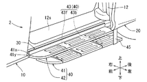
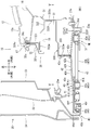
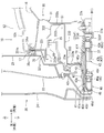
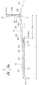
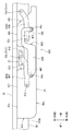
- FIG. 3 is an enlarged schematic perspective view of a part of the vehicle showing the vehicle step device. It is the III-III sectional view taken on the line of FIG. It is sectional drawing of the vehicle which made the sliding door the closed state. It is a top view of a part of vehicle showing a step device for vehicles.
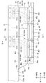
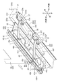
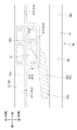
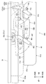
- FIG. 6 is a schematic cross-sectional view of each step plate corresponding to the cross-sectional view taken along line VI-VI of FIG. 5. It is a lower part perspective view of a vehicle showing a step device for vehicles. It is a bottom view of a part of vehicle showing the mode of position displacement of the first step board.
- FIG. 3 is an enlarged schematic perspective view of a part of the vehicle showing the vehicle step device. It is the III-III sectional view taken on the line of FIG. It is sectional drawing of the vehicle which made the sliding door the closed state.
- It is a top view of a part of vehicle showing a step device for vehicles.
- FIG. 6 is a schematic cross-sectional view of each step
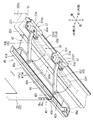
- FIG. 6 is a perspective top view of a portion of the vehicle showing the first step plate in the storage position. It is a lower part perspective view of a vehicle showing a step device for vehicles of a modification.
- FIG. 5 is a bottom view of a part of the vehicle showing the vehicle step device according to the second embodiment.
- FIG. 9 is a bottom view showing a mode of positional displacement of each step plate of the second embodiment.
- 1 is a perspective view of a known vehicle step device.
- FIGS. 1 to 12 For the sake of convenience, in each drawing, arrow lines indicating the front-rear direction, the left-right direction, and the up-down direction of the vehicle are illustrated. Further, in the embodiments described below, the left-right direction of the vehicle is defined as the vehicle width direction, the left side of the vehicle is the vehicle width direction outer side (vehicle outer side), and the right side of the vehicle is the vehicle width direction inner side. In each figure, for convenience, the arrow indicating the direction of the vehicle may be referred to as left side (outside) and right side (inside).
- the vehicle 2 shown in FIG. 1 includes a vehicle body 10 that forms the outer shape of the vehicle and a vehicle step device 40. Further, the vehicle body 10 is provided with a front door opening 11 and a rear door opening 12.
- the front door opening 11 is an opening corresponding to a front seat such as a driver's seat or a passenger seat, and is configured to be openable / closable by a front door 15 rotatable about a door hinge (not shown).
- a rear door opening 12 (details described later) is an opening corresponding to a rear seat and is configured to be opened and closed by a slide door 20 (details described later) that slides in the vehicle front-rear direction.
- a vehicle step device 40 is installed on the lower edge side (rocker 30 described later) of the rear door opening 12 as shown in FIG.
- the vehicle step device 40 has, as main components, a first step plate 41 and a second step plate 42 that serve as treads, and a four-node link mechanism 43 as a support mechanism (details of each component are described below. See below).
- the first step plate 41 is installed under the rocker 30 via the four-bar linkage 43, and moves from the storage position to the use position when the slide door 20 opens as shown in FIGS. 3 and 4. (Positional displacement) is possible. In this type of configuration, it is desirable that the first step plate 41 at the use position is largely projected from the vehicle from the viewpoint of passenger occupancy.
- the rear door opening portion 12 shown in FIG. 3 is a portion corresponding to the door opening portion of the present disclosure, and the vehicle body 10 portion at the lower edge portion of the rear door opening portion 12 has a fixed step plate 12s and a rocker 30. It is provided.
- the rocker 30 is a tubular frame extending in the vehicle front-rear direction below the fixed step plate 12s, and has a support bracket 37 described later.
- the locker 30 includes a rocker inner 31, a rocker outer 330, and a side outer 35 that covers the upper left side of the rocker outer 330.
- the rocker inner 31 is a frame that extends in the vehicle front-rear direction, is formed in a substantially lateral U-shaped cross section, and is open on the left side (the vehicle width direction outer side). Flange portions 31u and 31d are formed at the upper end position and the lower end position of the rocker inner 31, respectively, and the floor panel 16 is fixed to the upper end corner portion of the rocker inner 31 by welding or the like in a state of being overlapped from above. ing.
- the rocker outer 330 shown in FIG. 3 is a plate-shaped member fitted into the rocker inner 31 from the left side.
- the rocker outer 330 is composed of an upper panel 331 having a substantially inverted L-shaped cross section, a plate-shaped ceiling panel 332 bent in a step shape, and a lower panel 333 having a substantially U-shaped horizontal cross-section.
- the upper panel 331 has a vertically oriented flange portion 331u formed at the upper end position and a horizontally oriented flange portion 331y formed at the lower end position.
- the vertical flange portion 331u at the upper end position is joined by welding or the like while being sandwiched between the flange portion 31u of the rocker inner 31 (upper end position) and the flange portion 35u of the side outer 35 (upper end position).
- a body-side weather strip 17 is fitted into each of the joined flange portions 35u, 331u, 31u.
- the body-side weather strip 17 allows the slide door 20 and a rear door opening portion of the vehicle body 10 to be described later.
- the left edge of the fixed step plate 12s is fixed to the upper portion of the body side weather strip 17, and the rocker inner 31 and the upper side of the floor panel 16 are covered by the fixed step plate 12s.
- An outer flange portion 332w of the ceiling panel 332 is joined to the lateral flange portion 331y of the upper panel 331 (lower end position) by welding or the like in a state of being overlapped from the lower side.
- the ceiling panel 332 is a panel that extends in the left-right direction while bending in a step shape, and the lower guide rail 19 is attached to the lower surface of the ceiling panel 332.
- the ceiling panel 332 is provided with a vertical wall portion 332t on the rear end side (right end side), and the vertical wall portion 332t is joined to the vertical wall portion of the rocker inner 31 by welding or the like.
- the lower panel 333 shown in FIG. 3 is formed in a substantially U-shaped cross section in a substantially horizontal direction, and on the left side thereof, a vertical mounting flange portion 333w for installing a second step plate 42 described later is provided.
- a vertical wall-shaped upper end flange portion 333u is formed at an upper end position on the right side (inside the vehicle width direction) of the lower panel 333, and a vertical wall-shaped lower end flange portion is also formed at a lower end position on the right side of the lower panel 333.
- the portion 333f is formed.
- the upper end flange portion 333u is joined to the vertical wall portion of the rocker inner 31 by welding or the like while being stacked on the vertical wall portion 332t of the ceiling panel 332.
- a space S1 is formed between the lower panel 333 and the ceiling panel 332, and a drive device (not shown) for the slide door 20 described later and the like are housed in the space S1 together with the lower guide rail 19 described above.
- the lower end flange portion 333f is overlapped with the flange portion 31d formed at the lower end position of the rocker inner 31 and joined by welding or the like.
- the lower end flange portion 333f of the lower panel 333 and the flange portion 31d of the rocker inner 31 will be referred to as lower end flange portions 333f and 31d of the rocker 30.
- a support bracket 37 is fixed to the lower side of the rocker 30.
- the support bracket 37 supports a four-node link mechanism 43 of a vehicle step device 40 described later from below (of the four-node link mechanism 43).
- the connection mode will be described later).
- the support brackets 37 of this embodiment are used in pairs as shown in FIGS. 5 and 7. As shown in FIG. 3, each of these support brackets 37 is fixed to the rocker 30 by straddling the lower end flange portions 333f, 31d of the rocker 30 and on the left and right sides thereof. That is, each support bracket 37 includes a straddle portion 37m that straddles the lower end flange portions 333f and 31d, and an inner flange portion 37e provided inside the straddle portion 37m.
- each support bracket 37 has support portions 37sf and 37sb (details will be described later) arranged on the left side of the lower end flange portions 333f and 31d as shown in FIG. 7, and on both front and rear sides of these support portions 37sf and 37sb.
- support portions 37sf and 37sb are each provided with an outer flange portion 37f.
- the outer flange portion 37f of the support bracket 37 is bolted to the lower panel 333 of the rocker outer 330 from below.
- the slide door 20 shown in FIGS. 1 to 3 is a member having a hollow closed cross section, and has a part of a connecting mechanism (bracket 45b) described later.
- the sliding door 20 has an outer dimension capable of covering the rear door opening 12, and is configured by a door outer panel 22 and a door inner panel 23 joined together at their peripheral portions.
- an exterior material 24 extending in the vehicle front-rear direction is provided on the lower left portion of the door outer panel 22.
- the lower end portion of the exterior material 24 projects to the left (outside in the vehicle width direction), and a space below which step plates 41 and 42 and a bracket 45b can be arranged is provided below the exterior material 24.
- a door side weather strip 23w capable of contacting the peripheral edge of the rear door opening 12 is provided near the peripheral edge of the door inner panel 23, a door side weather strip 23w capable of contacting the peripheral edge of the rear door opening 12 is provided.
- a guide roller unit is provided at each of the upper position, the center position in the height direction and the lower position of the door inner panel 23 shown in FIG. 4 (in FIG. 4, only the lower guide roller unit 25 is shown for convenience).
- a lower guide roller unit 25 is provided below the door inner panel 23, and the lower guide roller unit 25 is provided at a position higher than the door side weather strip 23w.
- a vertically oriented roller member (reference numeral omitted) is rotatably supported by the lower guide roller unit 25, and the roller member rolls on the lower guide rail 19 disposed in the space S1 of the rocker 30. It is fitted in a movable state.
- the roller members of the guide roller unit at the upper position and the central position are also rotatably fitted in the upper guide rail (not shown) and the central guide rail (not shown) of the vehicle body 10 shown in FIG. Has been.
- the lower guide rail 19 (and the upper guide rail and the central guide rail) shown in FIG. 3 has a planar shape so that the slide door 20 can move along the movement paths Do and Ds shown in FIG. .. Therefore, when the slide door 20 moves from the fully closed position to the half open position, the slide door 20 moves to the left (outward in the vehicle width direction) along the movement path Do and moves to the rear of the vehicle. When the slide door 20 moves from the half open position to the full open position, the slide door 20 moves rearward of the vehicle along the movement track Ds.
- the vehicle step device 40 shown in FIGS. 1 to 4 is a device for assisting an occupant's lifting operation, and includes a first step plate 41, a second step plate 42, and a four-bar linkage mechanism 43 (support mechanism). And a part of the connecting mechanism (rail portion 46).
- a four-bar linkage 43 which will be described later, is installed on the lower side of the rocker 30 together with the first step plate 41, supported by each support bracket 37.
- the second step plate 42 described later is installed on the rocker 30 side so as to be located above the first step plate 41. It is desirable that the height position (ground height) of both the step plates 41 and 42 from the ground is not too high in consideration of the occupant getting on and off.
- the ground clearance of the locker 30 is set to an appropriate height considering the obstacles on the ground. Therefore, in the present embodiment, the first step plate 41 is arranged on the left side (outside in the vehicle width direction) of the lower end flange portions 333f, 31d, and further at a height position higher than the lower end position (H1) of the lower end flange portions 333f, 31d. It is arranged. By installing the first step plate 41 on the lower side of the rocker 30 in this way, it is possible to set the ground height to an appropriate value while avoiding a situation in which the ground height of the first step plate 41 becomes too high as much as possible.
- the first step plate 41 shown in FIGS. 5 to 7 is a plate-like member that serves as a tread surface when an occupant gets on and off, and a four-joint link mechanism 43 (supporting mechanism), which will be described later, is used for the rocker 30. It is supported in parallel.
- the first step plate 41 is formed in a front and rear long strip plate shape, and has a first upper surface portion 41a to be a tread surface.
- the first upper surface portion 41a has a substantially rectangular shape when viewed from above, and a plurality of anti-slip portions 41X and a plurality of guide portions 41Y are provided to project upward.
- Each of the non-slip portions 41X is a vertical plate-shaped portion extending in the front-rear direction, and each of the anti-slip portions 41X has substantially the same shape and size.
- a plurality of anti-slip portions 41X (three in each figure) are provided in a row on the left and right on the first upper surface portion 41a, and the rows of the adjacent anti-slip portions 41X are appropriately arranged in the front-rear direction. It is arranged at intervals.
- Each of the guide portions 41Y shown in FIGS. 5 and 6 is a vertical plate-shaped portion that extends in the left-right direction, which is the position displacement direction of the first step plate 41 described later, and all the guide portions 41Y have substantially the same shape and the same size. It is said that.
- These guide portions 41Y are respectively arranged between the rows of the adjacent non-slip portions 41X, and in the first upper surface portion 41a of the present embodiment, the guide portions 41Y are arranged in a well-balanced manner in the front-rear direction. Is becoming Each guide portion 41Y extends so as to cross the row of each anti-slip portion 41X, and the vertical dimension is large so as to get over each anti-slip portion 41X. That is, with reference to FIG.
- each guide portion 41Y gradually inclines upward from the right end toward the left, and the anti-slip portion 41X arranged on the rightmost side is provided. It has an inner taper surface Y1 that can be overcome. Further, an upper end surface portion on the left side (outside in the vehicle width direction) from the apex of the inner taper surface Y1 is arranged above the remaining non-slip portion 41X, and the outer taper surface is gradually inclined downward toward the left end. It is Y2.
- the left edge 42d of the second step plate 42 described later is in contact with the upper end surface (Y1, Y2) of each guide portion 41Y, and the second step plate 42 has the upper end surface (Y1, Y2) of each guide portion 41Y. It is possible to relatively move left and right along Y2).
- the first upper surface portion 41a shown in FIG. 5 has a short front edge portion 41b and a rear edge portion 41c extending left and right, and a long left edge portion 41d extending front and rear, as a peripheral portion thereof. And a right edge portion 41e are provided.
- the front edge portion 41b extends substantially straight to the left and right, and the rear edge portion 41c is gradually inclined toward the left as it goes rearward.
- the left edge portion 41d is an edge portion on the left side (outside in the vehicle width direction) of the first step plate 41, and extends substantially linearly in the front-rear direction.
- the right edge portion 41e is an edge portion on the right side (inside the vehicle width direction) of the first step plate 41, and corresponds to the vehicle body side edge portion of the present disclosure.
- the right edge portion 41e of the first step plate 41 is provided with a general edge portion 411 and a concave portion 412 (separation portion 413).
- the general edge portion 411 is an edge portion that forms the right edge portion 41e excluding the recessed portion 412, and extends linearly in the front-rear direction so as to be substantially parallel to the left edge portion 41d.
- the recessed portion 412 is a portion formed by notching the first step plate 41 in a rectangular shape as viewed from above.
- the recessed position 412 is provided at a position corresponding to the front side support bracket 37 (front side support part 37sf) with the first step plate 41 at the storage position described later as a reference.
- the recessed portion 412 is recessed to the left side of the general edge portion 411, and the bottom edge of the recessed portion 412 is provided with a separation portion 413 that is substantially parallel to the right edge portion 41e. .. In the recessed position 412, there is no plate portion that should be the tread surface when viewed from above, and a relatively large gap (non-step region 60) may occur between the separated portion 413 and the rocker 30 as described later. ..
- the four-node link mechanism 43 shown in FIGS. 5 and 7 is a mechanism corresponding to the support mechanism of the present disclosure, and the first step can be adjusted in a state where the protrusion amount of the first step plate 41 to the left side (vehicle outer side) can be adjusted.
- the plate 41 can be supported with respect to the rocker 30. That is, the four-node link mechanism 43 supports the first step plate 41 with respect to the rocker 30 so as to be movable between the storage position and the use position, and the protrusion amount of the first step plate 41 can be adjusted by the position displacement.
- the four-bar linkage mechanism 43 includes a front support link 43f and a rear support link 43b corresponding to a pair of support links of the present disclosure.
- the front support link 43f and the rear support link 43b are plate-shaped members having the same length, and are axially connected to the first step plate 41 and the rocker 30, respectively, as described later.
- the base end portion of the front support link 43f and the base end portion of the rear support link 43b shown in FIGS. 5 and 7 are axially connected to the rocker 30 side through corresponding support brackets 37, respectively. Since the support links 43f and 43b are substantially the same in their shaft couplings, the details will be described below by taking the front support link 43f as an example.
- a base end portion of the front support link 43f is axially connected to a front support bracket 37 having a hat cross-sectional shape in a side view. Further, the front support bracket 37 is provided with a front support portion 37sf projecting downward with respect to the lower surface (lower panel 333) of the rocker 30.
- the front end of the front support link 43f is superposed on the front support part 37sf from above, and is axially connected to the front support part 37sf by the front rotation center shaft 43c in a horizontally rotatable state. .. In this way, the front support link 43f is axially connected to the front support portion 37sf projecting downward, and is placed under the first step plate 41.
- the front end of the front support link 43f is axially connected to the lower surface of the front part of the first step plate 41 by a front end connecting shaft 43x in a horizontally rotatable state.
- the base end portion of the rear support link 43b shown in FIGS. 5 and 7 is also axially connected to the rear support portion 37sb of the rear support bracket 37. That is, the base end portion of the rear support link 43b is also overlapped with the rear support portion 37sb from above, and is axially connected to the rear support portion 37sb by the rear rotation center shaft 43e in a horizontally rotatable state. ing.
- the tip portion of the rear support link 43b is axially connected to the lower surface side of the rear portion of the first step plate 41 by a tip connecting shaft 43y so as to be horizontally rotatable.
- the distance between the front and rear tip connecting shafts 43x and 43y connected to the first step plate 41 is equal to the distance between the rotation center shafts 43c and 43e connected to the front and rear supporting portions 37sf and 37sb. It is set to a value equal to the distance.
- the front support link 43f and the rear support link 43b are formed to have the same size. Therefore, the front support link 43f and the rear support link 43b of the four-bar linkage 43 are horizontally rotated, so that the first step plate 41 moves along the arc locus S while being held parallel to the rocker 30 in plan view. To move along.
- both the support links 43f and 43b horizontally rotate about the rotation center shafts 43c and 43e to a position substantially parallel to the rocker 30 (right rotation limit position) (see a two-dot broken line portion in FIG. 8).
- the tip portions of both the support links 43f and 43b rotate to the right (inward in the vehicle width direction) about the rotation center shafts 43c and 43e, so that the first step plate 41 has the two-dot broken line in FIG.
- the locker 30 is held in a storage position below.
- both the support links 43f and 43b horizontally rotate about the rotation center shafts 43c and 43e to a position substantially perpendicular to the rocker 30 (left rotation limit position) (see the solid line portion in FIG. 8).
- the tip portions of both the support links 43f and 43b rotate leftward (outward in the vehicle width direction) about the rotation center shafts 43c and 43e, whereby the first step plate 41 is shown by the solid line in FIG.
- the locker 30 is projected from the lower side to the left side and held in the use position.
- the second step plate 42 shown in FIGS. 5 to 7 is a plate-like member that serves as a tread surface when an occupant gets on and off, and is arranged above the first step plate 41. Is disposed on the locker 30 side.
- a fixed plate portion 42x is connected to the second step plate 42 via a hinge portion 42y so as to have a substantially inverted L-shaped cross section.
- the fixed plate portion 42x is formed in a longitudinal vertical wall shape in the front and rear, and is fixed to the mounting flange portion 333w of the lower panel 333 by a method such as fastening.
- the lower edge of the fixed plate portion 42x is arranged above the first step plate 41, and the second step plate 42 is connected via the hinge portion 42y.
- the hinge portion 42y is a hinge-shaped portion that connects the lower edge of the fixed plate portion 42x and the right portion (right edge 42e) of the second step plate 42.
- the left portion (left edge 42d) side of the second step plate 42 is vertically rotatable with respect to the fixed plate portion 42x about the axis A extending in the front-rear direction of the hinge portion 42y.
- the second step plate 42 shown in FIGS. 5 to 7 protrudes leftward (outward in the vehicle width direction) from the hinge portion 42y, and is supported by each guide portion 41Y of the first step plate 41 and is generally supported by the second step plate 42. They are arranged in parallel.
- the second step plate 42 is formed in the shape of a long strip in the front-rear direction and has a second upper surface portion 42a to be a tread surface.
- the second upper surface portion 42a has a substantially rectangular shape when viewed from above, and has front, rear, left, and right dimensions capable of covering the recessed portion 412 (the non-step region 60 described later) of the first upper surface portion 41a in the use position. ..
- the front-rear dimension of the second upper surface portion 42a of this embodiment is substantially the same as the front-rear dimension of the first upper surface portion 41a, and the left-right dimension of the second upper surface portion 42a is equal to or larger than the left-right dimension of the recessed portion 412. Is set to.
- the left and right dimensions of the second step plate 42 are smaller than those of the first upper surface portion 41a so that the second step plate 42 can be arranged between the slide door 20 and the rocker 30 in the closed state shown in FIG.
- the second upper surface portion 42a is provided with a plurality of upper anti-slip portions 42X in left and right rows, and the rows of the adjacent upper anti-slip portions 42X are adjacent to each other. They are arranged at appropriate intervals in the front-rear direction (in FIG. 5, the upper anti-skid portion is omitted for convenience). Then, referring to FIG. 5, the second upper surface portion 42a also has a short front edge 42b and a rear edge 42c extending left and right, and a long left edge 42d extending forward and backward, as a peripheral portion thereof. And a right edge 42e are provided.
- the front edge 42b is gradually curved toward the right side as it goes forward, and the rear edge 42c extends substantially straight to the left and right. Further, the left edge 42d and the right edge 42e extend substantially forward and backward in a straight line and are in parallel with each other.
- the left edge 42d is bent downward with respect to the second upper surface portion 42a as shown in FIG. 6, and the left edge 42d is the upper end surface (Y1, Y2) of each guide portion 41Y of the first step plate 41. ) Is in contact with.
- the coupling mechanism 45 shown in FIGS. 2 to 4 is a mechanism for coupling the first step plate 41 and the slide door 20, and includes a bracket 45b on the slide door 20 side and a rail portion 46 on the first step plate 41 side. It is configured.
- the bracket 45b is formed in a vertically long strip plate shape, and is fixed to the lower portion of the door outer panel 22 and the door inner panel 23 at the front end position of the slide door 20. Then, as shown in FIG. 3, the lower portion of the bracket 45b is inclined leftward as it goes downward, and is then bent at a right angle from the left end of the first step plate 41 to the lower side thereof to be held substantially horizontally.
- a rolling roller 45r is horizontally provided at the lower end of the bracket 45b which is held horizontally. The rolling roller 45r is rollably fitted to a rail portion 46, which will be described later, formed on the lower surface of the first step plate 41.
- the rail portion 46 of the first step plate 41 shown in FIG. 3 is formed in an inverted U-shape in cross section, and the rolling roller 45r is fitted from below. That is, the first step plate 41 and the slide door 20 are connected via the bracket 45b of the connecting mechanism 45, the rolling roller 45r, and the rail portion 46.
- the rail portion 46 is formed on the left end side of the first step plate 41, and is disposed below and on the right side (inside the vehicle width direction) of the exterior material 24 of the slide door 20. As shown in FIGS. 7 and 8, the rail portion 46 is composed of a front end bent portion 46a and a straight portion 46b, and the straight portion 46b extends in the front-rear direction along the left end of the lower surface of the first step plate 41.
- the front end bent portion 46a of the rail portion 46 is bent rightward with respect to the straight portion 46b at a predetermined angle. With reference to FIG. 8, the front end bent portion 46a of the rail portion 46 is formed along the movement locus Do when the slide door 20 starts moving from the fully closed position in the opening direction. Further, the linear portion 46b of the rail portion 46 is formed so as to intersect the movement locus Do and be parallel to the movement locus Ds of the slide door 20 from the half-open position to the fully-open position.
- step device for vehicle When the slide door 20 is in the fully closed position, as shown in FIG. 4, the first step plate 41 of the vehicle step device 40 is held in the lower storage position of the rocker 30. At this time, with respect to the front support link 43f and the rear support link 43b of the four-bar linkage mechanism 43, the rocker 30 is centered around the rotation center shafts 43c and 43e of the support portions 37sf and 37sb with reference to the two-dot broken line portion of FIG. It is rotated horizontally to a position almost parallel to (the limit position of right rotation). For this reason, the first step plate 41 in the storage position is arranged below the rocker 30 together with the four-node link mechanism 43 as shown in FIG.
- the left edge portion 41d of the first step plate 41 is in a state of being arranged at a position that substantially coincides with the left edge 42d of the second step plate 42 in the vertical direction as shown in FIG. Therefore, almost the entire width of the first step plate 41 is accommodated under the lower panel 333 of the rocker 30 and the second step plate 42, and is in a state of being well stored.
- the rolling roller 45r of the bracket 45b is located at the front end portion of the front end bent portion 46a of the rail portion 46 with reference to FIGS. 7 (two-dotted line) and FIG.
- the first step plate 41 is provided between the rocker 30 and the support links 43f and 43b in the height direction (vertical direction) with reference to FIGS. 3, 4 and 8 (two-dotted line). It is possible to displace from the use position to the storage position in the state of being arranged in. That is, in this embodiment, the first step plate 41 can be displaced in the height direction while being compactly arranged between the support links 43f and 43b and the rocker 30.
- the first step plate 41 in the retracted position is referred to FIG. 4, FIG. 8 and FIG. 9 from the left side (outside in the vehicle width direction) while being overlapped with at least a part of each support link 43f, 43b from the upper side. It is arranged next to the front support portion 37sf (in FIG. 9, for convenience, the support link portion overlapping the first step plate is shown with a hatch). That is, the first step plate 41 at the retracted position is arranged adjacent to or close to the left side of the front support portion 37sf in a state of overlapping the support links 43f and 43b facing the front-rear direction from the upper side.
- the first step plate 41 is placed next to the front support portion 37sf so as to overlap the support links 43f and 43b from the upper side, so that the first step plate 41 is more compact than the case where these are individually housed. It is configured to contribute to storage.
- at least a part of the first step plate 41 overlaps the support links 43f, 43b and the front support portion 37sf in the height direction and the vehicle width direction.
- at least a part of the first step plate 41 in the retracted position overlaps the support links 43f and 43b in the height direction and the front support portion 37sf in the vehicle width direction, so that the first step plate 41 can be stored compactly. It is a structure that surely contributes. Therefore, in this embodiment, the storage space of the first step plate 41 on the lower side of the locker 30 can be made as compact as possible.
- the right edge portion 41e of the first step plate 41 shown in FIG. 9 is provided with a concave portion 412 which is concave so as to avoid the front support portion 37sf.
- the front support portion 37sf is arranged in a recessed position 412 from the right side (inside in the vehicle width direction) so as to be fitted (inclusive state).
- an appropriate gap is provided between the separated portion 413 of the recessed position 412 and the front support portion 37sf, and the interference between the first step plate 41 and the front support portion 37sf is avoided in this gap. Is becoming In this way, by avoiding the interference between the first step plate 41 in the storage position and the front support portion 37sf in the recessed position 412, the configuration further contributes to compact storage of the first step plate 41.
- the first step plate 41 does not move and is held at the storage position.
- the rolling roller 45r on the sliding door 20 side reaches the linear portion 46b of the rail portion 46.
- the linear portion 46b of the rail portion 46 intersects with the movement locus Do when the slide door 20 starts moving from the fully closed position in the opening direction. Therefore, when the rolling roller 45r on the slide door 20 side reaches the linear portion 46b, the leftward (outward in the vehicle width direction) moving force of the slide door 20 is applied to the linear portion 46b of the rail portion 46 via the rolling roller 45r.
- the first step plate 41 is pressed to the left.
- the front support link 43f and the rear support link 43b of the four-bar linkage 43 rotate left about the rotation center shafts 43c, 43e of the corresponding support portions 37sf, 37sb, and the first step plate 41 moves. Move horizontally to the left in parallel with. Then, the rolling roller 45r moves rearward in the linear portion 46b of the rail portion 46 in accordance with the movement of the slide door 20 in the opening direction (rearward direction).
- both support links 43f and 43b of the four-bar linkage 43 rotate to the left rotation limit position as shown in FIGS.
- the plate 41 moves horizontally to the use position. In this way, when the slide door 20 moves from the half-open position to the fully-open position, the movement locus Ds of the slide door 20 becomes parallel to the linear portion 46b of the rail portion 46, so that the rolling roller 45r moves to the linear portion 46b of the rail portion 46.
- the first step plate 41 is held in the use position even if it moves backward inside (see FIGS. 2 and 3).
- the first step plate 41 is returned to the retracted position by the operation opposite to the above operation.
- the left edge 42d of the second step plate 42 relatively moves while being pushed up gradually along the outer tapered surface Y2 of each guide portion 41Y, so as to get over each of the non-slip portions 41X of the first upper surface portion 41a. You can move. Then, the left edge 42d of the second step plate 42 reaches the inner tapered surface Y1 at the right end of each guide portion 41Y and descends, so that the second step plate 42 and the first step plate 41 in the use position. It will return to a substantially parallel state. In this way, in this embodiment, the first step plate 41 can be moved relative to the second step plate 42 without being disturbed by each of the antiskid portions 41X as much as possible.
- the second step plate 42 is moved along the upper end surface (Y1, Y2) of each guide portion 41Y. It can be moved up and down smoothly.
- each step plate in use position (formation of non-step area)
- the first step plate 41 is in a state of largely protruding toward the left side (outside in the vehicle width direction) of the rocker 30.
- the recessed portion 412 is exposed to the left side of the rocker 30, so that the recessed portion 412 is separated from the separated portion 413 in the vehicle width direction (left-right direction).
- a relatively large gap is provided between the locker 30 and the locker 30.
- a large gap between the separated portion 413 and the rocker 30 is a non-step area 60 having no portion that serves as a tread surface in the vertical direction.
- the first step plate 41 can be made to largely project, but in this type of configuration, excellent boarding / alighting performance should be ensured even if the non-step region 60 is formed.
- the second step plate 42 of the present embodiment is arranged on the rocker 30 so as to cover the non-step area 60 from the vertical direction as shown in FIGS. 5 to 7. That is, the second step plate 42 is in a state of being bridged between the separated portion 413 of the first step plate 41 and the rocker 30, and is in a state of covering the non-step region 60 from the upper side. In this way, in the present embodiment, the second step plate 42 is arranged so as to cover the non-step area 60 formed between the separated portion 413 at the use position and the rocker 30, so that excellent boarding / alighting performance is ensured. It is a contributing structure.
- the second upper surface portion 42a of the second step plate 42 is similar to the first upper surface portion 41a of the first step plate 41. It can be used more appropriately as a tread.
- the first step plate 41 is projected to the left side (outside in the vehicle width direction) of the second step plate 42 on the rocker 30 side as shown in FIG.
- the left edge 42d of the second upper surface portion 42a is arranged on the portion 41e side. Therefore, the first upper surface portion 41a and the second upper surface portion 42a can be used as a substantially continuous tread surface, and the left and right dimensions L1 of both the upper surface portions 41a, 42a to be the tread surface can be increased. There is.
- the protrusion amount of the first step plate 41 can be adjusted while the non-step area 60 is covered by the second step plate 42, excellent boarding / alighting performance can be secured. Further, in the present embodiment, since the non-step area 60 can be covered by the second step plate 42 with the first step plate 41 in the use position as a reference, it has a configuration that contributes to ensuring excellent entry / exit performance. Further, in the present embodiment, since the second step plate 42 is arranged above the non-step area 60, it is possible to utilize the second step plate 42 as a tread surface more appropriately.
- the first step plate 41 in the use position is projected to the outside of the vehicle with respect to the second step plate 42 on the vehicle body 10 side so that both step plates 41, 42 serve as a tread surface.
- the plate part to be used can be large.
- since the first step plate 41 at the time of position displacement is in contact with the second step plate 42 via the guide portion 41Y extending in the position displacement direction, these both step plates 41, 42 are smoothly moved. Can be moved relative to. Therefore, according to the present embodiment, it is possible to provide the vehicle step device 40 capable of adjusting the amount of protrusion of the first step plate 41 while ensuring excellent entry / exit performance.
- the first step plate 41 is displaced in the height direction while being compactly arranged between the support links 43f and 43b and the rocker 30 (vehicle body).
- the first step plate 41 in the retracted position overlaps at least a part of each of the support links 43f and 43b from above and is arranged next to the front support portion 37sf. Therefore, the first step plate 41 and the support mechanism (43) are Is configured to contribute to the compact storage of the first step plate 41 as compared with the case where they are individually housed.
- at least a part of the first step plate 41 in the retracted position overlaps the support links 43f and 43b in the height direction and the front support portion 37sf in the vehicle width direction.
- the compact storage ensures a positive contribution.
- the configuration since the interference between the first step plate 41 and the front support portion 37sf can be avoided by the recessed position 412 as the interference avoiding structure, the configuration contributes to compact storage of the first step plate 41. Is becoming Further, in this embodiment, since the recess position 412 as the interference avoiding structure is formed by utilizing the edge portion (right edge portion 41e) of the first step plate 41, the configuration contributes to the simplification of the device configuration. ing. Therefore, according to the present embodiment, it is possible to provide the vehicle step device 40 capable of storing the first step plate 41 in a more compact manner.
- the configuration of the first step plate can take various configurations in addition to the above-described configuration.
- the first step plate 41A of the modified example shown in FIG. 10 has substantially the same basic configuration as the first step plate of the first example, but all the right edge portions 41e are separated portions 413A. Is different from the first embodiment. That is, in the first step plate 41A of the modified example, the left and right dimensions are relatively short, and the entire right edge portion 41e is formed at a position corresponding to the separated portion of the first embodiment. Therefore, when the first step plate 41A of the present modification is set to the use position, a relatively large gap (non-step area 60A) is generated between the entire right edge portion 41e serving as the separated portion 413A and the rocker 30.
- the second step plate 42 can be installed on the rocker 30 side as in the first embodiment, and the non-step region 60A can be covered from the upper side by the second step plate 42.
- the upper surface portions of the step plates 41A and 42 can be used as a substantially continuous tread surface, and the left and right dimensions of both upper surface portions that are the tread surfaces can be increased.
- the first step plate 41A at the retracted position is arranged next to the front support portion 37sf in the vehicle width direction (left-right direction) in a state of overlapping the support links 43f and 43b from the upper side (FIG. (See the dashed double-dotted part of 10.)
- the entire right edge portion 41e of the first step plate 41A is arranged so as to avoid the front support portion 37sf at the storage position.
- an appropriate gap is provided between the entire right edge portion 41e (separated portion 413A) and the front support portion 37sf, and this gap avoids interference between the first step plate 41A and the front support portion 37sf. It is in a state.
- the entire right edge portion 41e has the interference avoiding structure, so that the interference with the front support portion 37sf can be more surely avoided, and the rocker side configuration (not shown) other than the front support portion 37sf can be further ensured. It is possible to avoid the interference of as much as possible.
- the vehicle step device 40A of the second embodiment shown in FIG. 11 and FIG. 12 detailed description will be given by assigning corresponding reference numerals to the configurations having substantially the same basic configuration as the vehicle step device of the first embodiment. Omit it.
- the vehicle step device 40A of the second embodiment includes a first step plate 41, a second step plate 42A, a four-node link mechanism 43A (support mechanism), and a rail portion (not shown). have.
- the second embodiment is different from the first embodiment in that the second step plate 42A is installed in the four-bar linkage 43A.
- the first step plate 41 has substantially the same basic configuration as the corresponding members of the first embodiment, and the right edge portion 41e of the first step plate 41 has a general edge portion 411, a recessed portion 412, and a separation position. A part 413 (interference avoidance structure) is provided. Also in this embodiment, as shown in FIG. 11, the first step plate 41 can be compactly arranged between the support links 43f and 43b and the rocker 30 in the vertical direction. Further, since the first step plate 41 at the storage position overlaps with the support links 43f and 43b from the upper side and is arranged next to the front support portion 37sf, the first step plate 41 contributes to compact storage of the first step plate 41. ..
- the four-bar linkage 43A includes a front support link 43f and a rear support link 43b corresponding to a pair of support links of the present disclosure, and both support links 43f and 43b are plate-shaped members formed with equal length. is there.
- the base ends of the support links 43f and 43b are axially connected to the support portions 37sf and 37sb of the rocker 30 by rotation center shafts 43c and 43e, as in the first embodiment.
- the tip ends of the support links 43f and 43b are also axially connected to the lower side of the first step plate 41 by tip connecting shafts 43x and 43y.
- the front support link 43f and the rear support link 43b are respectively provided with intermediate support portions 44f and 44b for axially connecting a second step plate 42A described later. That is, the front support link 43f is provided with the front intermediate support portion 44f protruding leftward (outside in the vehicle width direction) with the four-bar linkage 43A in the storage position as a reference.
- the front side intermediate support portion 44f is formed on the front end side of the front support link 43f facing the front-rear direction, and is arranged between the front end portion and the base end portion.
- a rear intermediate support portion 44b protruding leftward is also provided in the middle of the rear support link 43b.
- the rear intermediate support portion 44b is also formed between the base end portion and the front end portion of the rear support link 43b, similarly to the front intermediate support portion 44f.
- the front intermediate support portion 44f and the rear intermediate support portion 44b are disposed at substantially the same position in the left-right direction, and are disposed on the left side of the corresponding tip connecting shafts 43x and 43y in the storage position.
- the second step plate 42A shown in FIG. 11 is axially connected to the front intermediate support portion 44f and the rear intermediate support portion 44b via intermediate shafts 44x and 44y.
- the second step plate 42A is movable (driven) between the storage position and the use position together with the support links 43f and 43b, and is arranged below the first step plate 41.
- the second step plate 42A is a plate-shaped member that extends forward and backward between the front support link 43f and the rear support link 43b, and has a main body 42B that covers the recessed position 412.
- the main body portion 42B is a generally rectangular plate-like portion that is long in the front-rear direction, and the front end side of the main body portion 42B is axially connected to the front intermediate support portion 44f via the front intermediate shaft 44x.
- a bridge portion 42C is provided behind the main body portion 42B, and the rear end side of the bridge portion 42C is axially connected to the rear intermediate support portion 44b via the rear intermediate shaft 44y.
- the bridge portion 42C is bent rightward so as to form a substantially U shape so as to avoid the tip connecting shaft 43y of the rear support link 43b in the storage position.
- the second step plate 42A in the retracted position in FIG. 11 is supported by being axially connected to the respective intermediate support portions 44f and 44b in a state of facing the front-rear direction so as to be parallel to the rocker 30.
- the main body portion 42B of the second step plate 42A in this state is arranged relatively on the left side because the intermediate support portions 44f, 44b project leftward (outward in the vehicle width direction) from the support links 43f, 43b. It is in a state. That is, the main body portion 42B of the second step plate 42A is arranged on the left side of each of the tip connecting shafts 43x, 43y, and further on the left side of the separated portion 413 of the recess position 412. In this way, the second step plate 42A in the storage position is compactly arranged so as to overlap the first step plate 41 in the storage position from the lower side, and is further arranged so as not to interfere with the front support portion 37sf.
- both support links 43f and 43b of the four-bar linkage 43A rotate to the left rotation limit position, and the first step plate 41 horizontally moves to the use position.
- the first step plate 41 pivotally supported by the tip connecting shafts 43x and 43y is arranged at the use position so that the first step plate 41 protrudes relatively to the left.
- the respective intermediate support portions 44f and 44b follow the respective support links 43f and 43b, and rotate synchronously on the right side (inner side in the vehicle width direction) of the respective support links 43f and 43b.
- the respective intermediate support portions 44f, 44b rotate at positions closer to the respective rotation center shafts 43c, 43e than the respective tip connecting shafts 43x, 43y, whereby the movement amount to the left becomes relatively small. Therefore, the second step plate 42A pivotally supported by the respective intermediate support portions 44f, 44b is gradually arranged on the right side of the respective tip connecting shafts 43x, 43y while maintaining the front-back posture. Then, the second step plate 42A that has reached the use position is placed on the right side of the first step plate 41, and is placed so as to cover the recessed portion 412 serving as the non-step region 60 from below.
- the second step plate 42A in the use position is arranged on the right side of the tip connecting shafts 43x, 43y by following the rotation of the support links 43f, 43b, and thereby the non-step area 60 is formed.
- the second step plate 42A covers the recessed portion 412, so that the left and right dimensions of the tread surface in the recessed portion can be secured.
- the second step plate 42A can be made to follow the first step plate 41 with good performance via the four-bar linkage 43 (supporting mechanism). That is, the second step plate 42A at the storage position is compactly arranged so as to overlap the first step plate 41 by being arranged on the outer side in the vehicle width direction with respect to the respective tip connecting shafts 43x and 43y. Further, the second step plate 42A in the use position is arranged on the inner side in the vehicle width direction with respect to the respective tip connecting shafts 43x and 43y, so that the non-step region 60 can be more surely covered.
- the vehicle step device is not limited to the above-described embodiment, and various other embodiments may be adopted.
- the four-node link mechanism 43 is used as a support mechanism for the first step plate 41, and the first step plate 41 is moved from the storage position to the use position by the force of the sliding door 20 moving in the opening direction.
- the first step plate 41 is moved from the storage position to the use position by the force of the front door 15 (swing door) moving in the opening direction, or manually moved from the storage position to the use position. It is possible.
- first step plate and the second step plate can be provided with a plurality of or a single anti-slip portion, and the anti-slip portion can be omitted.
- the relative movement of the first step plate and the second step plate is possible, it is possible to omit part or all of the guide portion from the first step plate.
- the amount of protrusion of the first step plate can be changed as appropriate, but it is desirable to set so that all or part of the recessed portion protrudes from the vehicle body.
- the installation position of the vehicle step device can also be set as appropriate, and a door opening on the rear side of the vehicle can be assumed in addition to the door opening on the side of the vehicle.
- the configuration (shape, size, arrangement position, etc.) of the second step plates 42, 42A is illustrated, but the configuration of the second step plate is not limited.
- the second step plate of the first embodiment only needs to have a shape and dimensions that cover at least the recessed portion of the first step plate, may cover the non-step region from below, and ensures proper boarding / alighting performance. If possible, it is also permissible to leave a part of the non-step region in an uncovered state.
- the configurations of the second step plates of the first and second embodiments can be used in an appropriate combination.
- the first step plate at the storage position is arranged next to the support portion from the outside of the vehicle in a state of overlapping with at least a part of each support link from above.
- the first step plate in the retracted position can be placed next to the support mechanism without overlapping the support link.
- an example of the interference avoidance structure has been described, but the structure of the interference avoidance structure is not limited.
- the shape of the recessed portion can be changed according to the shape and size of the support portion, and in addition to the generally rectangular shape when viewed from above, various polygonal shapes, semicircular shapes, It may have various shapes such as a semi-elliptical shape.
Landscapes
- Engineering & Computer Science (AREA)
- Mechanical Engineering (AREA)
- Vehicle Step Arrangements And Article Storage (AREA)
- Braking Elements And Transmission Devices (AREA)
Priority Applications (1)
| Application Number | Priority Date | Filing Date | Title |
|---|---|---|---|
| CN201980050555.8A CN112512867B (zh) | 2018-11-20 | 2019-10-28 | 车辆用踏板装置 |
Applications Claiming Priority (2)
| Application Number | Priority Date | Filing Date | Title |
|---|---|---|---|
| JP2018-217637 | 2018-11-20 | ||
| JP2018217637A JP7040416B2 (ja) | 2018-11-20 | 2018-11-20 | 車両用ステップ装置 |
Publications (1)
| Publication Number | Publication Date |
|---|---|
| WO2020105375A1 true WO2020105375A1 (ja) | 2020-05-28 |
Family
ID=70773998
Family Applications (1)
| Application Number | Title | Priority Date | Filing Date |
|---|---|---|---|
| PCT/JP2019/042165 Ceased WO2020105375A1 (ja) | 2018-11-20 | 2019-10-28 | 車両用ステップ装置 |
Country Status (3)
| Country | Link |
|---|---|
| JP (1) | JP7040416B2 (enExample) |
| CN (1) | CN112512867B (enExample) |
| WO (1) | WO2020105375A1 (enExample) |
Cited By (2)
| Publication number | Priority date | Publication date | Assignee | Title |
|---|---|---|---|---|
| US20210070227A1 (en) * | 2019-09-09 | 2021-03-11 | Aisin Seiki Kabushiki Kaisha | Step device for vehicle |
| CN114537282A (zh) * | 2020-11-19 | 2022-05-27 | 丰田车体株式会社 | 车辆结构 |
Families Citing this family (3)
| Publication number | Priority date | Publication date | Assignee | Title |
|---|---|---|---|---|
| JP7355455B2 (ja) * | 2019-09-09 | 2023-10-03 | 株式会社アイシン | 車両用ステップ装置 |
| JP7355453B2 (ja) | 2019-09-09 | 2023-10-03 | 株式会社アイシン | 車両用ステップ装置 |
| JP7355454B2 (ja) | 2019-09-09 | 2023-10-03 | 株式会社アイシン | 車両用ステップ装置 |
Citations (4)
| Publication number | Priority date | Publication date | Assignee | Title |
|---|---|---|---|---|
| JPH0486551U (enExample) * | 1990-11-30 | 1992-07-28 | ||
| JP2007269086A (ja) * | 2006-03-30 | 2007-10-18 | Mazda Motor Corp | 車両用乗降ステップ構造 |
| JP2008238933A (ja) * | 2007-03-27 | 2008-10-09 | Aisin Seiki Co Ltd | 車両用ステップ装置、及び車両用ステップ装置の配置構造 |
| JP2019137385A (ja) * | 2018-02-09 | 2019-08-22 | トヨタ車体株式会社 | 車両用ステップ装置 |
Family Cites Families (4)
| Publication number | Priority date | Publication date | Assignee | Title |
|---|---|---|---|---|
| KR100570398B1 (ko) * | 2002-11-28 | 2006-04-11 | 현대자동차주식회사 | 자동차의 자동 작동식 사이드 스텝 부재 |
| TR201619818A2 (tr) * | 2016-12-28 | 2018-07-23 | Ford Otomotiv Sanayi As | Kayar kapi basamaği mekani̇zmasi |
| CN108146351B (zh) * | 2017-12-21 | 2019-10-22 | 连云港中昊房车有限公司 | 一种上下车踏步装置及汽车 |
| JP6692872B2 (ja) * | 2018-09-28 | 2020-05-13 | 大王製紙株式会社 | 芳香機能付き衛生薄葉紙及びその製造方法 |
-
2018
- 2018-11-20 JP JP2018217637A patent/JP7040416B2/ja active Active
-
2019
- 2019-10-28 WO PCT/JP2019/042165 patent/WO2020105375A1/ja not_active Ceased
- 2019-10-28 CN CN201980050555.8A patent/CN112512867B/zh active Active
Patent Citations (4)
| Publication number | Priority date | Publication date | Assignee | Title |
|---|---|---|---|---|
| JPH0486551U (enExample) * | 1990-11-30 | 1992-07-28 | ||
| JP2007269086A (ja) * | 2006-03-30 | 2007-10-18 | Mazda Motor Corp | 車両用乗降ステップ構造 |
| JP2008238933A (ja) * | 2007-03-27 | 2008-10-09 | Aisin Seiki Co Ltd | 車両用ステップ装置、及び車両用ステップ装置の配置構造 |
| JP2019137385A (ja) * | 2018-02-09 | 2019-08-22 | トヨタ車体株式会社 | 車両用ステップ装置 |
Cited By (4)
| Publication number | Priority date | Publication date | Assignee | Title |
|---|---|---|---|---|
| US20210070227A1 (en) * | 2019-09-09 | 2021-03-11 | Aisin Seiki Kabushiki Kaisha | Step device for vehicle |
| US11518312B2 (en) * | 2019-09-09 | 2022-12-06 | Aisin Seiki Kabushiki Kaisha | Step device for vehicle |
| CN114537282A (zh) * | 2020-11-19 | 2022-05-27 | 丰田车体株式会社 | 车辆结构 |
| CN114537282B (zh) * | 2020-11-19 | 2024-03-29 | 丰田车体株式会社 | 车辆结构 |
Also Published As
| Publication number | Publication date |
|---|---|
| JP7040416B2 (ja) | 2022-03-23 |
| CN112512867A (zh) | 2021-03-16 |
| CN112512867B (zh) | 2023-04-04 |
| JP2020082916A (ja) | 2020-06-04 |
Similar Documents
| Publication | Publication Date | Title |
|---|---|---|
| WO2020105375A1 (ja) | 車両用ステップ装置 | |
| JP7070354B2 (ja) | 車両用ステップ装置 | |
| JP7066598B2 (ja) | 車両用ステップ構造 | |
| WO2020105374A1 (ja) | 車両用ステップ装置 | |
| US20140259938A1 (en) | Invisible sliding door link structure | |
| CN110386070B (zh) | 可动式踏板装置 | |
| EP1403111B1 (en) | Sliding door structure for vehicle | |
| JP5217365B2 (ja) | 車両用スライドドア構造 | |
| CN114537282B (zh) | 车辆结构 | |
| JP2008285964A (ja) | スライドドア開閉制御装置 | |
| HK40038637A (en) | Step device for vehicle | |
| JPH09277833A (ja) | 車両用スライド式ドア開閉装置 | |
| HK40038637B (en) | Step device for vehicle | |
| HK40038939A (en) | Step device for vehicle | |
| HK40038939B (en) | Step device for vehicle | |
| JP4178073B2 (ja) | 走行車両 | |
| HK40047708B (en) | Vehicle step plate structure | |
| JP4229751B2 (ja) | 走行車両 | |
| JP2004291796A (ja) | 自動車の車体構造 | |
| JP2018203077A (ja) | 車両用スライドドア装置 | |
| CN119928533A (zh) | 车辆的滑动门结构 | |
| JP2024112768A (ja) | 車両用ステップ装置 | |
| HK40047708A (en) | Vehicle step plate structure | |
| JP2006070596A (ja) | 車両用スライドドアの開閉装置 | |
| JP4419413B2 (ja) | 車両用スライドドア構造 |
Legal Events
| Date | Code | Title | Description |
|---|---|---|---|
| 121 | Ep: the epo has been informed by wipo that ep was designated in this application |
Ref document number: 19886073 Country of ref document: EP Kind code of ref document: A1 |
|
| NENP | Non-entry into the national phase |
Ref country code: DE |
|
| 122 | Ep: pct application non-entry in european phase |
Ref document number: 19886073 Country of ref document: EP Kind code of ref document: A1 |