WO2020105303A1 - セルコントローラ、バッテリコントローラ、電池管理システムおよび電池システム - Google Patents
セルコントローラ、バッテリコントローラ、電池管理システムおよび電池システムInfo
- Publication number
- WO2020105303A1 WO2020105303A1 PCT/JP2019/039876 JP2019039876W WO2020105303A1 WO 2020105303 A1 WO2020105303 A1 WO 2020105303A1 JP 2019039876 W JP2019039876 W JP 2019039876W WO 2020105303 A1 WO2020105303 A1 WO 2020105303A1
- Authority
- WO
- WIPO (PCT)
- Prior art keywords
- balancing
- cell
- time
- cells
- discharge
- Prior art date
- Legal status (The legal status is an assumption and is not a legal conclusion. Google has not performed a legal analysis and makes no representation as to the accuracy of the status listed.)
- Ceased
Links
Images

Classifications
-
- H—ELECTRICITY
- H02—GENERATION; CONVERSION OR DISTRIBUTION OF ELECTRIC POWER
- H02J—ELECTRIC POWER NETWORKS; CIRCUIT ARRANGEMENTS OR SYSTEMS FOR SUPPLYING OR DISTRIBUTING ELECTRIC POWER; SYSTEMS FOR STORING ELECTRIC ENERGY
- H02J7/00—Circuit arrangements for charging or discharging batteries or for supplying loads from batteries
- H02J7/50—Circuit arrangements for charging or discharging batteries or for supplying loads from batteries acting upon multiple batteries simultaneously or sequentially
- H02J7/52—Circuit arrangements for charging or discharging batteries or for supplying loads from batteries acting upon multiple batteries simultaneously or sequentially for charge balancing, e.g. equalisation of charge between batteries
-
- B—PERFORMING OPERATIONS; TRANSPORTING
- B60—VEHICLES IN GENERAL
- B60L—PROPULSION OF ELECTRICALLY-PROPELLED VEHICLES; SUPPLYING ELECTRIC POWER FOR AUXILIARY EQUIPMENT OF ELECTRICALLY-PROPELLED VEHICLES; ELECTRODYNAMIC BRAKE SYSTEMS FOR VEHICLES IN GENERAL; MAGNETIC SUSPENSION OR LEVITATION FOR VEHICLES; MONITORING OPERATING VARIABLES OF ELECTRICALLY-PROPELLED VEHICLES; ELECTRIC SAFETY DEVICES FOR ELECTRICALLY-PROPELLED VEHICLES
- B60L58/00—Methods or circuit arrangements for monitoring or controlling batteries or fuel cells, specially adapted for electric vehicles
- B60L58/10—Methods or circuit arrangements for monitoring or controlling batteries or fuel cells, specially adapted for electric vehicles for monitoring or controlling batteries
- B60L58/18—Methods or circuit arrangements for monitoring or controlling batteries or fuel cells, specially adapted for electric vehicles for monitoring or controlling batteries of two or more battery modules
- B60L58/22—Balancing the charge of battery modules
-
- G—PHYSICS
- G01—MEASURING; TESTING
- G01R—MEASURING ELECTRIC VARIABLES; MEASURING MAGNETIC VARIABLES
- G01R31/00—Arrangements for testing electric properties; Arrangements for locating electric faults; Arrangements for electrical testing characterised by what is being tested not provided for elsewhere
- G01R31/36—Arrangements for testing, measuring or monitoring the electrical condition of accumulators or electric batteries, e.g. capacity or state of charge [SoC]
- G01R31/382—Arrangements for monitoring battery or accumulator variables, e.g. SoC
-
- H—ELECTRICITY
- H01—ELECTRIC ELEMENTS
- H01M—PROCESSES OR MEANS, e.g. BATTERIES, FOR THE DIRECT CONVERSION OF CHEMICAL ENERGY INTO ELECTRICAL ENERGY
- H01M10/00—Secondary cells; Manufacture thereof
- H01M10/42—Methods or arrangements for servicing or maintenance of secondary cells or secondary half-cells
- H01M10/425—Structural combination with electronic components, e.g. electronic circuits integrated to the outside of the casing
-
- H—ELECTRICITY
- H01—ELECTRIC ELEMENTS
- H01M—PROCESSES OR MEANS, e.g. BATTERIES, FOR THE DIRECT CONVERSION OF CHEMICAL ENERGY INTO ELECTRICAL ENERGY
- H01M10/00—Secondary cells; Manufacture thereof
- H01M10/42—Methods or arrangements for servicing or maintenance of secondary cells or secondary half-cells
- H01M10/44—Methods for charging or discharging
- H01M10/441—Methods for charging or discharging for several batteries or cells simultaneously or sequentially
-
- H—ELECTRICITY
- H01—ELECTRIC ELEMENTS
- H01M—PROCESSES OR MEANS, e.g. BATTERIES, FOR THE DIRECT CONVERSION OF CHEMICAL ENERGY INTO ELECTRICAL ENERGY
- H01M10/00—Secondary cells; Manufacture thereof
- H01M10/42—Methods or arrangements for servicing or maintenance of secondary cells or secondary half-cells
- H01M10/48—Accumulators combined with arrangements for measuring, testing or indicating the condition of cells, e.g. the level or density of the electrolyte
- H01M10/482—Accumulators combined with arrangements for measuring, testing or indicating the condition of cells, e.g. the level or density of the electrolyte for several batteries or cells simultaneously or sequentially
-
- H—ELECTRICITY
- H02—GENERATION; CONVERSION OR DISTRIBUTION OF ELECTRIC POWER
- H02J—ELECTRIC POWER NETWORKS; CIRCUIT ARRANGEMENTS OR SYSTEMS FOR SUPPLYING OR DISTRIBUTING ELECTRIC POWER; SYSTEMS FOR STORING ELECTRIC ENERGY
- H02J7/00—Circuit arrangements for charging or discharging batteries or for supplying loads from batteries
- H02J7/80—Circuit arrangements for charging or discharging batteries or for supplying loads from batteries including monitoring or indicating arrangements
- H02J7/82—Control of state of charge [SOC]
-
- B—PERFORMING OPERATIONS; TRANSPORTING
- B60—VEHICLES IN GENERAL
- B60L—PROPULSION OF ELECTRICALLY-PROPELLED VEHICLES; SUPPLYING ELECTRIC POWER FOR AUXILIARY EQUIPMENT OF ELECTRICALLY-PROPELLED VEHICLES; ELECTRODYNAMIC BRAKE SYSTEMS FOR VEHICLES IN GENERAL; MAGNETIC SUSPENSION OR LEVITATION FOR VEHICLES; MONITORING OPERATING VARIABLES OF ELECTRICALLY-PROPELLED VEHICLES; ELECTRIC SAFETY DEVICES FOR ELECTRICALLY-PROPELLED VEHICLES
- B60L2240/00—Control parameters of input or output; Target parameters
- B60L2240/80—Time limits
-
- H—ELECTRICITY
- H01—ELECTRIC ELEMENTS
- H01M—PROCESSES OR MEANS, e.g. BATTERIES, FOR THE DIRECT CONVERSION OF CHEMICAL ENERGY INTO ELECTRICAL ENERGY
- H01M10/00—Secondary cells; Manufacture thereof
- H01M10/42—Methods or arrangements for servicing or maintenance of secondary cells or secondary half-cells
- H01M10/425—Structural combination with electronic components, e.g. electronic circuits integrated to the outside of the casing
- H01M2010/4271—Battery management systems including electronic circuits, e.g. control of current or voltage to keep battery in healthy state, cell balancing
-
- H—ELECTRICITY
- H01—ELECTRIC ELEMENTS
- H01M—PROCESSES OR MEANS, e.g. BATTERIES, FOR THE DIRECT CONVERSION OF CHEMICAL ENERGY INTO ELECTRICAL ENERGY
- H01M10/00—Secondary cells; Manufacture thereof
- H01M10/42—Methods or arrangements for servicing or maintenance of secondary cells or secondary half-cells
- H01M10/425—Structural combination with electronic components, e.g. electronic circuits integrated to the outside of the casing
- H01M2010/4278—Systems for data transfer from batteries, e.g. transfer of battery parameters to a controller, data transferred between battery controller and main controller
-
- H—ELECTRICITY
- H01—ELECTRIC ELEMENTS
- H01M—PROCESSES OR MEANS, e.g. BATTERIES, FOR THE DIRECT CONVERSION OF CHEMICAL ENERGY INTO ELECTRICAL ENERGY
- H01M2220/00—Batteries for particular applications
- H01M2220/20—Batteries in motive systems, e.g. vehicle, ship, plane
-
- Y—GENERAL TAGGING OF NEW TECHNOLOGICAL DEVELOPMENTS; GENERAL TAGGING OF CROSS-SECTIONAL TECHNOLOGIES SPANNING OVER SEVERAL SECTIONS OF THE IPC; TECHNICAL SUBJECTS COVERED BY FORMER USPC CROSS-REFERENCE ART COLLECTIONS [XRACs] AND DIGESTS
- Y02—TECHNOLOGIES OR APPLICATIONS FOR MITIGATION OR ADAPTATION AGAINST CLIMATE CHANGE
- Y02E—REDUCTION OF GREENHOUSE GAS [GHG] EMISSIONS, RELATED TO ENERGY GENERATION, TRANSMISSION OR DISTRIBUTION
- Y02E60/00—Enabling technologies; Technologies with a potential or indirect contribution to GHG emissions mitigation
- Y02E60/10—Energy storage using batteries
Definitions
- the present invention relates to a cell controller and a battery controller, and a battery management system and a battery system using them.
- a large number of secondary battery cells are connected in series.
- the assembled battery (battery system) is generally used.
- a battery management device is connected to such an assembled battery via a wire harness for capacity calculation and protection management of each battery cell. This battery management device manages each battery cell by controlling the charging / discharging state of each battery cell.
- the battery management device in order to reduce the voltage variation between the battery cells, it is known that the battery cells are individually discharged to perform balancing to equalize the voltage of each battery cell.
- the battery management device normally uses the electric power of a low-voltage battery such as a lead storage battery mounted in the vehicle separately from the assembled battery to perform balancing while the vehicle is stopped. Therefore, in order to prevent the battery from running out while the vehicle is stopped, it is necessary to suppress the power consumption of the battery management device during balancing as much as possible.
- Patent Document 1 The technology of Patent Document 1 below has been proposed for reducing the power consumption of the battery management device during balancing.
- the battery management device disclosed in Patent Document 1 is a battery control system that individually adjusts the capacities of a plurality of lithium secondary batteries that form an assembled battery, and measures the open circuit voltage of each of the lithium secondary batteries.
- Means for calculating the capacity adjustment time of the lithium secondary battery from the open circuit voltage measured by the voltage measuring means, and the capacity adjustment time calculated by the operation means for the lithium secondary battery A capacity adjusting means for adjusting the capacity; and an operation control means for operating the voltage measuring means and the calculating means for a predetermined time when the assembled battery is left unused for a certain period, and the capacity adjusting means is
- the capacity adjustment of the lithium secondary battery is started within a predetermined time and the capacity adjustment of the lithium secondary battery is continued even after the lapse of the predetermined time, and the voltage measuring means and the computing means consume less power after the lapse of the predetermined time. It is characterized by being in a power state.
- Patent Document 1 has a problem that the device becomes complicated because a plurality of timers corresponding to a plurality of battery cells are arranged.
- a cell controller includes a balancing unit that discharges or charges a plurality of secondary batteries to balance the state of charge of the secondary batteries, and a first unit that measures an elapsed time from the start of the balancing.
- a timer a receiving unit that receives a balancing command signal including information about the balancing time of the secondary battery, an elapsed time from the start of the balancing measured by the first timer, and the receiving unit received.
- a first control unit that controls the balancing unit based on the balancing command signal, and the receiving unit receives the information for the plurality of secondary batteries by the balancing command signal once. To do.
- a battery controller is capable of communicating with the cell controller, and includes a second control unit that calculates a balancing time of the plurality of secondary batteries, and the balancing calculated by the second control unit.
- a transmitting unit that transmits a balancing command signal including time information to the cell controller, and the transmitting unit transmits the information for the plurality of secondary batteries by the balancing command signal once.
- a battery management system includes the cell controller and the battery controller.
- a battery system according to the present invention includes the battery management system described above and a plurality of secondary batteries balanced by the battery management system.
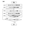
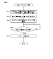
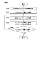
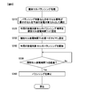
- FIG. 3 is a flowchart of balancing control according to the first embodiment of the present invention. It is a flowchart of an odd cell balancing process. It is a flowchart of an even cell balancing process. It is a flowchart of the balancing control in the 2nd Embodiment of this invention. It is a flow chart of all-cell balancing processing. It is a flow chart of balancing control in a 3rd embodiment of the present invention. It is a flowchart of an individual cell balancing process.
- FIG. 1 is a diagram showing a battery management system and a battery system according to an embodiment of the present invention.
- the battery management system shown in FIG. 1 has a plurality of cell controllers (hereinafter abbreviated as “CCU”) 1 and a battery controller (hereinafter abbreviated as “BCU”) 2, and m (m) units connected in series. Is for managing the battery cells 3 of an arbitrary natural number).
- the battery management system and the m battery cells 3 are combined to form the battery system of the present embodiment.
- the battery cell 3 may be simply referred to as “cell”.
- the battery system of the present embodiment is used by being mounted in a vehicle such as a hybrid vehicle (HEV) or an electric vehicle (EV), and supplies electric power for driving a motor of the vehicle.
- a vehicle such as a hybrid vehicle (HEV) or an electric vehicle (EV)
- HEV hybrid vehicle
- EV electric vehicle
- the battery system according to the present embodiment will be described by taking the battery system used for driving the motor of the vehicle as an example.
- the CCU 1 is connected to each of the plurality of battery cells 3 and manages the corresponding battery cell 3 based on a command from the BCU 2.
- the management of the battery cells 3 performed by the CCU 1 includes balancing for adjusting the variation of the state of charge (SOC: State of Charge) of the battery cells 3 within a certain range.
- SOC State of Charge
- Each CCU 1 balances the corresponding battery cells 3 for the purpose of widening the range of SOC that can be used in the battery cells 3. The details of balancing by the CCU 1 will be described later.
- This balancing command signal includes information about the balancing time of the plurality of battery cells 3 to which each CCU 1 is connected.
- the BCU 2 also receives information such as cell voltage, cell temperature, and current value transmitted from each CCU 1, and generates a balancing command signal based on these information.
- Each battery cell 3 is configured by using a secondary battery such as a lithium-ion battery, supplies DC power for generating AC power for driving a motor to an inverter (not shown) that is a load, and also performs regenerative power generation. It charges the DC power generated based on the AC power from the inside motor and commercial power supply.
- a secondary battery such as a lithium-ion battery
- FIG. 1 m battery cells 3 are represented by BC1 to BCm, respectively, and lines connecting the CCU 1 and the positive and negative electrodes of each battery cell 3 are represented by L0 to Lm. Further, the BCU 2 is connected to the lead storage battery 4.
- CCU1 and BCU2 that constitute the battery management system of the present embodiment will be described.
- the CCU 1 operates by using the battery cells 3 as a power source, and has a cell controller IC (hereinafter abbreviated as “cell controller IC”) 5, a first control unit 7, a first timer 8, a time management unit 9, and a CCU side radio device 10. , CCU side antenna 11.
- the cell controller IC5 includes a balancing unit 12 and an AD converter (not shown).
- the CCU side wireless device 10 includes a CCU side transmitting unit 13 and a CCU side receiving unit 14.
- FIG. 1 among the plurality of CCUs 1 in the battery management system of the present embodiment, a CCU 1A connected to each battery cell 3 of BCm-2, BCm-1, BCm arranged on the highest potential side of the assembled battery. , CCU1B connected to each battery cell 3 of BC1, BC2, and BC3 arranged on the lowest potential side of the assembled battery is illustrated, and CCU1 connected to another battery cell 3 is not shown. ..
- the number of CCUs 1 included in the battery management system and the number of battery cells 3 connected to each CCU 1 are not limited to the example of FIG. 1 and can be set arbitrarily. In the following, the configuration and operation of a plurality of CCU1 will be described by taking CCU1A as an example.
- the CCU side reception unit 14 provided in the CCU side radio 10 receives the radio signal transmitted from the BCU 2 via the CCU side antenna 11.
- the above-mentioned balancing command signal including information on the balancing time of each battery cell 3, a start signal including a start command for the CCU 1, and the like are received from the BCU 2 by wireless signals.
- the CCU-side receiving unit 14 demodulates the wireless signal and outputs it to the first control unit 7.
- the CCU side transmission unit 13 provided in the CCU side radio 10 modulates the signal input from the first control unit 7 to generate a radio signal and transmits it to the BCU 2 via the CCU side antenna 11.
- the information such as the cell voltage, the cell temperature, and the current value acquired from each battery cell 3 is transmitted to the BCU 2 by a wireless signal.
- PSK Phase Shift Keying
- a radio signal modulation method used in the CCU side radio 10 there is, for example, IEEE802.15.4.
- the first control unit 7 controls the balancing unit 12 provided in the cell controller IC 5 based on the balancing command signal wirelessly received by the CCU-side receiving unit 14 to perform balancing control of the battery cells 3. At this time, the first control unit 7 performs balancing control using the time measured by the first timer 8. The first timer 8 measures the elapsed time since the balancing unit 12 started balancing. The details of the balancing control by the first control unit 7 will be described later.
- the first control unit 7 uses, for example, arithmetic processing circuits such as CPU (Central Processing Unit), FPGA (Field Programmable Gate Array), and ASIC (Application Specific Integrated Circuit), and various programs used in combination with these. Each is composed.
- the balancing unit 12 carries out balancing of the battery cells 3 by discharging or charging the plurality of battery cells 3 to which the CCU 1 is connected under the control of the first control unit 7.
- the balancing unit 12 has a plurality of balancing switches (not shown) connected between the positive and negative electrodes of each battery cell 3, and the plurality of balancing switches are respectively controlled according to the control of the first control unit 7. By turning on or off, each battery cell 3 can be discharged or charged for balancing.
- the balancing unit 12 is configured by using, for example, a part of a circuit in the cell controller IC5 which is an integrated circuit and various electric components provided in association with the cell controller IC5.
- the first control unit 7 performs control to shift the CCU 1 to a predetermined low power consumption state after completing the balancing control of the balancing unit 12.
- the CCU 1 stops the operation of each unit in the CCU 1 except for the part necessary for receiving the activation signal when the activation signal is transmitted from the BCU 2. As a result, it is possible to reduce the power consumption after the completion of balancing.
- an abnormality occurs such that the CCU 1 cannot shift to the low power consumption state, the electric charge of the battery cell 3 is continuously discharged by the operation of the CCU 1, and in the worst case, the vehicle may not be able to run.
- This abnormality is caused by, for example, a failure of the first timer 8 or a failure of the first control unit 7, when the balancing cannot be stopped even after a predetermined balancing time elapses, or low cost after the balancing is stopped. This includes a case where a standby state in which the power consumption is larger than the power state is continued.
- the CCU 1 has a time management unit 9.
- the time management unit 9 has a function of stopping the CCU 1 when the CCU 1 has an abnormality such that the CCU 1 cannot shift to the low power consumption state.
- a stop time longer than the time required for balancing control is set in the time management unit 9, and the CCU 1 can be stopped when the elapsed time from the start of balancing exceeds this stop time. Is becoming For the stop time in the time management unit 9, a predetermined fixed value or a set value from the BCU 2 can be used.
- the time management unit 9 may monitor the abnormality of the first timer 8 and stop the CCU 1 when detecting the abnormality.
- the time management unit 9 may be realized, for example, as a function of a CPU or an FPGA used as the first control unit 7, or may be realized using hardware different from the first control unit 7. ..
- the activation signal wirelessly transmitted from BCU2 is received in the low power consumption state
- CCU1 is activated and cancels the low power consumption state.
- the CCU-side receiving unit 14 receives the balancing command signal transmitted from the BCU 2 after activation
- the first control unit 7 uses the first timer 8 to manage the balancing of the plurality of battery cells 3.
- the BCU 2 operates by using the lead storage battery 4 as a power source, and includes a power supply unit 15, a second control unit 16, a second timer 17, a BCU side wireless device 18, and a BCU side antenna 19.
- the BCU side wireless device 18 includes a BCU side transmitting unit 20 and a BCU side receiving unit 21.
- the power supply unit 15 supplies operating power to each part of the BCU 2 based on the power supplied from the lead storage battery 4.
- the BCU side receiving unit 21 receives a radio signal transmitted from the CCU 1 via the BCU side antenna 19.
- This wireless signal includes information such as the cell voltage, cell temperature, and current value of each battery cell 3 acquired by the CCU 1.
- the BCU-side receiving unit 21 demodulates the wireless signal and outputs it to the second control unit 16.
- the BCU-side transmission unit 20 modulates these signals to generate a wireless signal, and the wireless signal is sent to the CCU 1 via the BCU-side antenna 19. Send.
- the second control unit 16 uses the information of each battery cell 3 included in the signal received and demodulated by the BCU-side receiving unit 21 to determine the SOC, SOH (State of Health), and allowable power amount of each battery cell 3. Etc. are calculated. Further, the second control unit 16 calculates the balancing time of each battery cell 3 based on the calculated SOC, generates a balancing command signal from the calculation result, and outputs the balancing command signal to the BCU side transmitting unit 20. When the balancing command signal is input from the second control unit 16, the BCU side transmission unit 20 modulates the balancing command signal to generate a radio signal, and transmits the radio signal to the CCU 1 via the BCU side antenna 19.
- the balancing time of the plurality of battery cells 3 connected to CCU1 is transmitted from BCU2 to CCU1.
- the second controller 16 shifts to a predetermined low power consumption state.
- the BCU 2 collectively transmits the information on the balancing times of the plurality of battery cells 3 connected to the CCU 1 to the CCU 1 by one balancing command signal. Therefore, in the CCU 1, the CCU side receiving unit 14 receives the information on the balancing time for the plurality of battery cells 3 to be balanced by the one balancing command signal transmitted from the BCU 2. As a result, the activation of the BCU2 necessary for performing the balancing and the transmission of the balancing command signal from the BCU2 to the CCU1 can be completed once. Therefore, it is possible to reduce the power consumption of the BCU 2 during balancing.
- the second timer 17 measures the elapsed time after the BCU 2 shifts to the low power consumption state, and when the elapsed time reaches a predetermined activation time, instructs the power supply unit 15 to activate the BCU 2 and To restart. At this time, the power supply unit 15 restarts the supply of operating power to each part of the BCU 2 according to the instruction from the second timer 17.
- the second control unit 16 sets the startup time in the second timer 17, and then shifts the BCU 2 to the low power consumption state.
- the second timer 17 instructs the power supply unit 15 to activate the BCU 2 after the set activation time has elapsed.
- a start signal is sent to CCU1 to start CCU1.
- the BCU 2 transmits an information acquisition command for each battery cell 3 to the CCU 1.
- CCU1 acquires the information of each battery cell 3 according to the information acquisition command from BCU2, and transmits to BCU2.
- BCU2 calculates the SOC and balancing time of each cell using the information of each battery cell 3 sent from CCU1, and sends the balancing command signal to CCU1.
- part or all of the information of the battery cell 3 acquired by the CCU 1 may be replaced with the information acquired by the BCU 2.
- a current value may be obtained by arranging a shunt resistor connected in series with a plurality of battery cells 3 and obtaining a voltage drop at the shunt resistor by an AD converter (not shown) owned by the BCU 2. ..
- information on the voltage or SOC of each cell may be transmitted from the BCU2 to the CCU1 by a balancing command signal.
- the CCU 1 can calculate the balancing time from the voltage of each cell and the SOC. That is, as long as the CCU 1 can determine the balancing time of each cell, it is possible to include arbitrary information in the balancing command signal as information about the balancing time.
- BCU2 After transmitting the balancing command signal, BCU2 shifts to the low power consumption state again.
- the CCU 1 receives the balancing command signal from the BCU 2, the CCU 1 shifts to a low power consumption state after performing balancing.
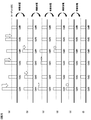
- FIG. 2 is a diagram showing an example of balancing control according to the first embodiment of the present invention.
- six battery cells 3 are connected to one CCU 1, and an example of balancing control for aligning the SOCs of the six battery cells 3 is shown in each figure of (a) to (f).
- FIGS. 2A to 2F “Cell1” to “Cell6” respectively correspond to the six battery cells 3 connected to the same CCU1, and the SOCs of the six battery cells 3 are indicated by bar graphs. It represents.
- the SOC of each battery cell 3 corresponds to the balancing time of each battery cell 3.
- balancing in the battery system of the present embodiment is performed for the purpose of aligning the SOCs of a plurality of cells connected in series in order to widen the range of SOCs that can be used in the battery cells 3.
- the balancing control of the present embodiment will be described by taking passive type balancing in which SOCs are aligned by discharging the battery cells 3 as an example.
- active-type balancing in which SOCs are aligned by discharging or charging each cell and moving charges between the cells may be applied.
- the active type balancing it is possible to suppress the power consumption of the plurality of battery cells 3 as a whole.
- each battery cell 3 (hereinafter referred to as an “even cell”) connected to an even number counted from the low potential side or from the low potential side.
- Each battery cell 3 (hereinafter referred to as an “odd cell”) connected in an odd-numbered count was set to a condition in which they can be simultaneously discharged.
- the voltage applied to the balancing unit 12 when the cells adjacent to each other are simultaneously discharged will be described.
- the connection line Lm-1 connected to the positive electrode of the cell BCm-1 and the negative electrode of the cell BCm-1.
- the connection line Lm-1 and the connection line Lm-2 have a low impedance.
- the voltage between the connection line Lm-1 and the connection line Lm becomes about twice the voltage before discharge.
- the balancing unit 12 uses a balancing switch arranged between the connection line Lm-1 and the connection line Lm-2.
- the balancing switch arranged between the connection line Lm-2 connected to the positive electrode of the cell BCm-2 and the connection line Lm-3 connected to the negative electrode of the cell BCm-2 is turned on.
- the impedance between the connection line Lm-1 and the connection line Lm-2 and between the connection line Lm-2 and the connection line Lm-3 are set to low impedance.
- the voltage between the connection line Lm-1 and the connection line Lm becomes about three times the voltage before discharge.
- the voltage applied to the balancing unit 12 becomes higher than that in one case.
- the voltage applied to the balancing unit 12 increases in accordance with the number. Therefore, it is understood that when the cells adjacent to each other are discharged at the same time, the voltage resistance of the cell controller IC5 including the balancing unit 12 needs to be increased.
- the voltage resistance of the cell controller IC5 including the balancing unit 12 needs to be increased.
- simultaneous discharge of adjacent cells may lead to increase in size of the cell controller IC5.
- FIG. 2A shows the SOCs of Cell1 to Cell6 before the start of balancing.
- the SOC of Cell 6 is the smallest. Therefore, in balancing, the SOC of Cell6 is used as the target SOC, and the SOC of Cell1 to Cell5 is discharged so that the SOCs of Cell1 to Cell5 are aligned with this target SOC.
- the first control unit 7 When balancing is started from the state shown in FIG. 2A, the first control unit 7 first discharges odd cells, that is, Cell1, Cell3, and Cell5. Of these odd cells, the one that has the closest SOC to the target SOC, that is, the smallest SOC, is Cell5. Therefore, the first control unit 7 sets the discharge time of the odd-numbered cells so that the SOC of the Cell 5 drops to the target SOC, and discharges the Cell 1, Cell 3, and Cell 5 during the discharge time. As a result, the state shown in FIG.
- the first controller 7 When the discharge of the odd-numbered cells is completed and the state shown in FIG. 2B is reached, the first controller 7 subsequently discharges the even-numbered cells, that is, Cell2 and Cell4. Although the Cell 6 is also an even cell, the SOC of the Cell 6 is set as the target SOC, so the Cell 6 is excluded from the balancing target. Of these even cells to be balanced, the one that has the closest SOC to the target SOC, that is, the smallest SOC, is Cell2. Therefore, the first control unit 7 sets the discharge time of the even-numbered cells so that the SOC of Cell2 decreases to the target SOC, and discharges Cell2 and Cell4 during the discharge time. As a result, the state shown in FIG.
- the discharge of odd cells and the discharge of even cells are alternately repeated. That is, in the state of FIG. 2 (c), among the odd-numbered cells, Cell1 and Cell3 whose SOC is not the target SOC are discharged, and the state of FIG. 2 (d) is obtained. In the state shown in FIG. 2D, among the even-numbered cells, the cell 4 whose SOC is not the target SOC is discharged, and the state shown in FIG. 2E is obtained. In the state of FIG. 2E, among the odd-numbered cells, the cell 1 whose SOC is not the target SOC is discharged, resulting in the state of FIG. 2F. As a result, the SOCs of Cell1 to Cell6 are aligned as shown in FIG. 2 (f).
- the SOC can be made uniform for all of the six battery cells 3 whose SOC was not uniform before the start of balancing.
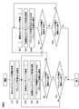
- FIG. 3 is a flowchart of balancing control in the first embodiment of the present invention.
- the first control unit 7 performs the balancing control shown in the flowchart of FIG. carry out.
- step S10 the first control unit 7 receives the balancing time of each cell from the CCU-side receiving unit 14.
- the CCU side receiving unit 14 receives the information of the balancing time of each cell included in the balancing command signal received from the BCU 2 from the CCU side receiving unit 14 and acquires it.
- step S20 the first control unit 7 sets a balancing target cell based on the balancing time of each cell received in step S10.
- cells having a balancing time of 0, that is, cells excluding cells having a minimum SOC and being a target SOC are set as balancing target cells.
- step S30 the first control unit 7 performs an odd cell balancing process for performing odd cell balancing control.
- odd cell balancing balancing is performed on the odd cells among the balancing target cells set in step S20.
- the odd cells excluded from the balancing target in step S50 which will be described later, are not set as the processing target in step S30.
- the details of the odd cell balancing process in step S30 will be described later with reference to the flowchart in FIG.
- step S40 the first control unit 7 updates the balancing time of each odd cell in the balancing target cell.
- the odd cell discharge time To set in the odd cell balancing process of step S30 is subtracted from the balancing time of each odd cell of the balancing target cells to update the balancing time of each odd cell.
- the method of setting the odd cell discharge time To will be described later in the description of the odd cell balancing process.
- step S50 the first control unit 7 excludes cells whose balancing time is 0 due to the update in step S40 from the balancing target. As a result, the cells whose SOC matches the target SOC in the odd cell balancing process in step S30 are excluded from the subsequent balancing targets.
- step S60 the first control unit 7 determines whether or not there is an even cell to be balanced. As a result, if at least one even-numbered cell remains in the balancing target cells, the process proceeds to step S80, and the even-numbered cell balancing process is performed subsequent to the odd-numbered cell balancing process in step S30. On the other hand, if no even cells remain in the balancing target cells, that is, if the SOCs of all the even cells match the target SOC and the balancing is completed, the process proceeds to step S70.
- step S70 the first control unit 7 determines whether or not there is an odd number cell to be balanced. As a result, when at least one odd cell remains in the balancing target cell, the process returns to step S30 and the odd cell balancing process is continued. On the other hand, if no odd number cell remains in the balancing target cell, that is, if the SOCs of all the odd number cells match the target SOC and the balancing is completed, the flowchart of FIG. 3 is ended.
- step S80 the first control unit 7 performs an even cell balancing process for performing even cell balancing control.
- this even cell balancing process balancing is performed for even cells among the balancing target cells set in step S20.
- the even cells excluded from the balancing target in step S100 which will be described later, are not set as the processing target in step S80.
- the details of the even cell balancing process in step S80 will be described later with reference to the flowchart in FIG.
- step S90 the first control unit 7 updates the balancing time of each even cell in the balancing target cells.
- the even cell discharge time Te set in the even cell balancing process in step S80 is subtracted from the balancing time of each even cell of the balancing target cells to update the balancing time of each even cell.
- a method of setting the even cell discharge time Te will be described later in the description of the even cell balancing process.
- step S100 the first control unit 7 excludes cells whose balancing time is 0 due to the update in step S90 from balancing targets. As a result, the cells whose SOC matches the target SOC in the even cell balancing process in step S80 are excluded from the subsequent balancing targets.
- step S110 the first control unit 7 determines whether or not there is an odd number cell to be balanced. As a result, when at least one odd cell remains in the balancing target cell, the process returns to step S30, and the odd cell balancing process is performed after the even cell balancing process of step S80. On the other hand, when no odd number cell remains in the balancing target cell, that is, when the SOCs of all the odd number cells match the target SOC and the balancing is completed, the process proceeds to step S120.
- step S120 the first control unit 7 determines whether or not there is an even cell to be balanced. As a result, when at least one even cell remains in the balancing target cell, the process returns to step S80 and the even cell balancing process is continued. On the other hand, when there is no even-numbered cell among the cells to be balanced, that is, when the SOCs of all the even-numbered cells match the target SOC and the balancing is completed, the flowchart of FIG. 3 is ended.
- the CCU 1 executes the balancing control as described above by the first control unit 7.
- the odd-numbered cell balancing process of step S30 and the even-numbered cell balancing process of step S80 are alternately and repeatedly executed until the balancing is completed for all the balancing target cells. Therefore, as described with reference to FIG. 2, the balancing of the odd cells and the balancing of the even cells can be alternately repeated to align the SOC of each cell with the target SOC.
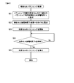
- FIG. 4 is a flowchart of the odd cell balancing process.
- step S31 the first control unit 7 specifies an odd cell having the shortest current balancing time, that is, an odd cell whose SOC is closest to the target SOC, among the odd cells in the current balancing target cell.
- the balancing time of each odd cell at this time when the odd cell balancing process is first performed in step S30, the balancing time received in step S10, that is, the balancing command signal received by the CCU-side receiving unit 14 from the BCU2 is received. Balancing time based on On the other hand, in the second and subsequent odd cell balancing processes, the balancing time updated in step S40 immediately before is used. Then, the current balancing time of the identified odd cell, that is, the minimum balancing time among the odd cells in the current balancing target cell is set to the odd cell discharge time To.
- step S32 the first control unit 7 sets the odd cell discharge time To set in step S31 in the first timer 8.
- step S33 the first control unit 7 starts balancing the odd number cells in the current balancing target cell.
- the first control unit 7 turns on the balancing switch corresponding to each odd cell of the balancing target cells among the plurality of balancing switches included in the balancing unit 12, and turns off the other balancing switches.
- the balancing unit 12 is controlled such that the positive and negative electrodes of each odd numbered cell of the balancing target cells are brought into a low impedance state and the discharge is started.
- step S34 the first control unit 7 uses the first timer 8 to determine whether or not the odd cell discharge time To has elapsed since the odd cell balancing was started in step S33.
- the first timer 8 measures the elapsed time from the start of balancing the odd cells in step S33, and when this elapsed time reaches the odd cell discharge time To set in step S32, the first timer 8
- the notification is output to the control unit 7.
- the first control unit 7 determines that the odd-numbered cell discharge time To has not elapsed until receiving the notification from the first timer 8, stays in step S34, and receives the notification from the first timer 8. Then, it is determined that the odd cell discharge time To has elapsed, and the process proceeds to step S35.
- step S35 the first control unit 7 stops the odd cell balancing started in step S33. At this time, the first control unit 7 controls the balancing unit 12 so that the discharging of each odd-numbered cell of the balancing target cell is stopped by turning off all the balancing switches included in the balancing unit 12.
- step S35 After the odd cell balancing is stopped in step S35, the first control unit 7 ends the flowchart of FIG. 4 and completes the odd cell balancing process. Then, the process returns to the flowchart of FIG. 3 and proceeds to the next step S40.
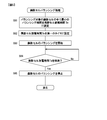
- FIG. 5 is a flowchart of the even cell balancing process.
- step S81 the first control unit 7 specifies an even cell having the shortest current balancing time, that is, an even cell whose SOC is closest to the target SOC among the even cells in the current balancing target cell.
- the balancing time of each even cell at this time if the even cell balancing process is first performed in step S80, the balancing time received in step S10, that is, the balancing command signal received by the CCU-side receiving unit 14 from the BCU2 is received. Balancing time based on On the other hand, in the second and subsequent even cell balancing processes, the balancing time updated in the immediately preceding step S90 is used. Then, the current balancing time of the identified even cell, that is, the minimum balancing time among the even cells in the current balancing target cell is set as the even cell discharge time Te.
- step S82 the first control unit 7 sets the even cell discharge time Te set in step S81 in the first timer 8.
- step S83 the first control unit 7 starts balancing even cells in the current balancing target cell.
- the first control unit 7 turns on the balancing switch corresponding to each even cell of the balancing target cells among the plurality of balancing switches included in the balancing unit 12, and turns off the other balancing switches.
- the balancing unit 12 is controlled such that the positive and negative electrodes of each even-numbered cell of the balancing target cells are brought into the low impedance state and the discharge is started.
- step S84 the first control unit 7 uses the first timer 8 to determine whether or not the even cell discharge time Te has elapsed since the even cell balancing was started in step S83.
- the first timer 8 measures the elapsed time since the even cell balancing was started in step S83, and when this elapsed time reaches the even cell discharge time Te set in step S82, the first timer 8 The notification is output to the control unit 7.
- the first control unit 7 determines that the even cell discharge time Te has not elapsed and stays at step S84 to receive the notification from the first timer 8. Then, it is determined that the even cell discharge time Te has elapsed, and the process proceeds to step S85.
- step S85 the first control unit 7 stops the even cell balancing started in step S83. At this time, the first control unit 7 controls the balancing unit 12 so that the discharging of each even-numbered cell of the balancing target cell is stopped by turning off all the balancing switches included in the balancing unit 12.
- step S85 When the even cell balancing is stopped in step S85, the first control unit 7 ends the flowchart of FIG. 5 and completes the even cell balancing process. Then, the process returns to the flowchart of FIG. 3 and proceeds to the next step S90.
- the CCU 1 measures the elapsed time from the start of balancing, with the balancing unit 12 that balances the state of charge of the battery cells 3 by discharging or charging the plurality of battery cells 3 that are secondary batteries.
- the first timer 8 the CCU-side receiving unit 14 that receives a balancing command signal including information about the balancing time of the battery cells 3, the elapsed time from the start of balancing measured by the first timer 8, and the CCU.
- the first control unit 7 that controls the balancing unit 12 based on the balancing command signal received by the side receiving unit 14 is provided.
- the CCU side receiving unit 14 receives the information regarding the balancing time for the plurality of battery cells 3 by one balancing command signal.
- the first control unit 7 sets each of the plurality of battery cells 3 whose balancing time is not 0 as a balancing target cell (step S20), and balances odd cells among the balancing target cells (step S30). To S50) and balancing of even cells among the balancing target cells (steps S80 to S100) are alternately repeated, and the balancing unit 12 is controlled. Since it did in this way, a plurality of battery cells 3 can be balanced in a short time, without enlarging cell controller IC5.
- Balancing of the odd number cells performed by the first control unit 7 includes the following processes.
- A1 Process of setting the minimum balancing time of odd cells in the balancing target cell as the odd cell discharge time To in the first timer 8 based on the balancing command signal or the updated balancing time (steps S31 and S32).
- A2) Processing for causing the balancing unit 12 to start discharging odd-numbered cells (step S33)
- A3) A process of stopping the discharging of the odd cells by the balancing unit 12 when the elapsed time from the start of discharging the odd cells measured by the first timer 8 reaches the odd cell discharge time To (steps S34 and S35).
- step S40 Processing for updating the balancing time of each odd cell of the balancing target cells based on the odd cell discharge time To (step S40)
- step S50 Processing for excluding odd cells whose balancing time after updating is 0 from balancing target cells (step S50)
- the balancing for even-numbered cells performed by the first control unit 7 includes the following processes.
- (B1) Process of setting the minimum balancing time of even cells in the balancing target cell as the even cell discharge time Te in the first timer 8 based on the balancing command signal or the updated balancing time (steps S81 and S82).
- step S83 Processing for causing the balancing unit 12 to start discharging even cells (step S83)
- step S83 Processing for causing the balancing unit 12 to start discharging even cells (step S83)
- step S83 A process of causing the balancing unit 12 to stop the discharging of the even cells when the elapsed time from the start of the discharging of the even cells measured by the first timer 8 reaches the even cell discharging time Te (steps S84 and S85).
- step S90 Processing for updating the balancing time of each even cell of the balancing target cells based on the even cell discharge time Te (step S90)
- step S100 Process of excluding even cells whose balancing time after updating is 0 from balancing target cells (step S100) Since it did in this way, in the 1st control part 7, the balancing with respect to an odd cell and the balancing with respect to an even cell can be performed appropriately, respectively.
- the CCU side receiving unit 14 wirelessly receives the balancing command signal. Since it did in this way, since wiring between CCU1 and BCU2 can be omitted, the configuration of the battery management system can be further simplified.
- the CCU 1 includes the time management unit 9 that stops the CCU 1 when the CCU 1 is abnormal. Since this is done, it is possible to prevent the electric power of the battery cell 3 from being wasted when an abnormality occurs in the CCU 1.
- the BCU 2 which can communicate with the CCU 1, stores information about the balancing time calculated by the second controller 16 and the second controller 16 that calculates the balancing time of the plurality of battery cells 3 that are secondary batteries.
- the BCU-side transmitter 20 that transmits the included balancing command signal to the CCU 1.
- the BCU side transmission unit 20 transmits information on the balancing time for the plurality of battery cells 3 by one balancing command signal. Since it did in this way, the power consumption of BCU2 during balancing can be suppressed.
- the BCU side transmitter 20 wirelessly transmits the balancing command signal. Since it did in this way, since wiring between CCU1 and BCU2 can be omitted, the composition of a battery management system can be simplified.
- the BCU 2 includes the second timer 17 that measures the time after the BCU 2 shifts to the predetermined low power consumption state.
- the second control unit 16 sets a predetermined activation time in the second timer 17, and then shifts the BCU 2 to the low power consumption state.
- the second timer 17 restarts the BCU 2 when the elapsed time after the BCU 2 shifts to the low power consumption state reaches the startup time. Since this is done, it is possible to further suppress the power consumption of the BCU 2 while periodically performing balancing.
- FIG. 6 is a flowchart of balancing control in the second embodiment of the present invention.
- the CCU 1 transmits, for example, a balancing command signal from the BCU 2 and is received by the CCU side receiving unit 14, the first control unit 7 performs the balancing control shown in the flowchart of FIG. carry out.
- step S10A the first control unit 7 receives the balancing time of each cell from the CCU-side receiving unit 14.
- the CCU-side receiving unit 14 receives, from the CCU-side receiving unit 14, information about the balancing time of each cell included in the balancing command signal received from the BCU 2.
- step S20A the first control unit 7 sets a balancing target cell based on the balancing time of each cell received in step S10A.
- each cell except for the cell having the balancing time of 0, that is, the cell having the minimum SOC and being the target SOC is set as the balancing target cell.
- step S30A the first control unit 7 performs all-cell balancing processing for performing balancing control of all cells.
- this all-cell balancing process balancing is performed on all balancing target cells set in step S20A.
- the cell excluded from the balancing target in step S50A described later is not set as the processing target in step S30A.
- the details of the all-cell balancing process in step S30A will be described later with reference to the flowchart in FIG.
- step S40A the first control unit 7 updates the balancing time of each cell in the balancing target cell.
- the balancing time of each cell is updated by subtracting the all-cell discharge time Ta set in the all-cell balancing process of step S30A from the balancing time of each balancing target cell.
- the method of setting the all-cell discharge time Ta will be described later in the explanation of the all-cell balancing process.
- step S50A the first control unit 7 excludes cells whose balancing time becomes 0 due to the update in step S40A from balancing targets. As a result, the cells whose SOC matches the target SOC in the all-cell balancing process in step S30A are excluded from the subsequent balancing targets.
- step S60A the first control unit 7 determines whether or not there is a balancing target cell. As a result, when at least one balancing target cell remains, the process returns to step S30A and the all-cell balancing process is continued. On the other hand, when no balancing target cell remains, that is, when the SOCs of all cells match the target SOC and the balancing is completed, the flowchart of FIG. 6 is ended.
- the CCU 1 executes the balancing control as described above by the first control unit 7.
- the all-cell balancing process of step S30A is repeatedly performed until the balancing is completed for all balancing target cells. Therefore, the SOC of each cell can be aligned with the target SOC.
- FIG. 7 is a flowchart of the all cell balancing process.
- step S31A the first control unit 7 identifies a cell having the shortest current balancing time, that is, a cell whose SOC is closest to the target SOC, among the current cells to be balanced.
- the balancing time of each cell at this time when the all-cell balancing process is first performed in step S30A, the balancing time received in step S10A, that is, the balancing command signal received from the BCU 2 by the CCU-side receiver 14 Based balancing time is used.
- the balancing time updated in step S40A immediately before is used.
- the current balancing time of the specified cell that is, the minimum balancing time of the current balancing target cells is set to the all-cell discharge time Ta.
- step S32A the first control unit 7 sets the all-cell discharge time Ta set in step S31A in the first timer 8.
- step S33A the first control unit 7 starts balancing all current balancing target cells.
- the first control unit 7 turns on the balancing switch corresponding to each balancing target cell among the plurality of balancing switches included in the balancing unit 12, and turns off the other balancing switches.
- the balancing unit 12 is controlled so that the positive and negative electrodes of each balancing target cell are brought into the low impedance state and the discharge is started.
- step S34A the first control unit 7 uses the first timer 8 to determine whether or not the all-cell discharge time Ta has elapsed since the balancing of all balancing target cells was started in step S33A.
- the first timer 8 measures the elapsed time from the start of balancing all the balancing target cells in step S33A, and when this elapsed time reaches the all-cell discharge time Ta set in step S32A, The notification is output to one control unit 7.
- the first control unit 7 determines that the all-cell discharge time Ta has not elapsed until receiving the notification from the first timer 8, stays in step S34A, and receives the notification from the first timer 8. Then, it is determined that the total cell discharge time Ta has elapsed, and the process proceeds to step S35A.
- step S35A the first control unit 7 stops the balancing of all balancing target cells started in step S33A. At this time, the first control unit 7 controls the balancing unit 12 so that the discharging of each balancing target cell is stopped by turning off all the balancing switches included in the balancing unit 12.
- step S35A After stopping the balancing of all balancing target cells in step S35A, the first control unit 7 finishes the flowchart of FIG. 7 and finishes the all-cell balancing process. Then, the process returns to the flowchart of FIG. 6 and proceeds to the next step S40A.
- the first control unit 7 sets each of the plurality of battery cells 3 whose balancing time is not 0 as a balancing target cell (step S20A), and repeatedly performs balancing for all balancing target cells.
- the balancing unit 12 is controlled (steps S30A to 50A). Since it did in this way, since the balancing time of a plurality of battery cells 3 can be shortened further, it is possible to further reduce the electric power of the battery cells 3 which CCU1 consumes at the time of balancing. However, it may be necessary to increase the size of the cell controller IC 5 as compared with the first embodiment.
- Balancing for all balancing target cells performed by the first control unit 7 includes the following processes.
- C1 Processing of setting the minimum balancing time of the balancing target cells as the total cell discharge time Ta in the first timer 8 based on the balancing command signal or the updated balancing time (steps S31A and S32A).
- C2) Processing for causing the balancing unit 12 to start discharging of the balancing target cell (step S33A)
- C3 When the elapsed time from the discharge start of the balancing target cells measured by the first timer 8 reaches the all-cell discharge time Ta, the process of stopping the balancing unit 12 from discharging the balancing target cells (steps S34A and S35A).
- step S40A Processing of updating the balancing time of each cell of the balancing target cells based on the total cell discharge time Ta (step S40A)
- step S50A Processing for excluding cells whose balancing time after updating is 0 from balancing target cells (step S50A) Since it did in this way, the 1st control part 7 can perform balancing about all the balancing object cells appropriately.
- a third embodiment of the present invention will be described.
- a balancing control method for discharging cells one by one will be described.
- the configurations of the battery management system and the battery system in this embodiment, and the configurations of CCU1 and BCU2 are the same as those described in FIG. 1 in the first embodiment. is there.
- the point that the BCU2 transmits the information of the balancing time of the plurality of battery cells 3 connected to the CCU1 to the CCU1 by one balancing command signal is the same as in the first embodiment. Therefore, these descriptions will be omitted below.
- FIG. 8 is a flowchart of balancing control in the third embodiment of the present invention.
- the CCU 1 transmits, for example, a balancing command signal from the BCU 2 and is received by the CCU side receiving unit 14, the first control unit 7 performs the balancing control shown in the flowchart of FIG. carry out.
- step S10B the first control unit 7 receives the balancing time of each cell from the CCU-side receiving unit 14.
- the CCU-side receiving unit 14 receives from the CCU-side receiving unit 14 and obtains information on the balancing time of each cell included in the balancing command signal received from the BCU 2. ..
- step S20B the first control unit 7 sets a balancing target cell based on the balancing time of each cell received in step S10B.
- each cell except for the cell having the balancing time of 0, that is, the cell having the minimum SOC and being the target SOC is set as the balancing target cell.
- step S30B the first control unit 7 performs an individual cell balancing process for performing balancing control of each balancing target cell.
- this individual cell balancing process balancing is performed individually for each balancing target cell set in step S20B.
- the cell excluded from the balancing target in step S50B described later is not set as the processing target in step S30B.
- the details of the individual cell balancing process in step S30B will be described later with reference to the flowchart in FIG.
- step S50B the first control unit 7 excludes the cells that have been balanced by the individual cell balancing processing in step S30B from the balancing target. As a result, the cell whose SOC matches the target SOC in the individual cell balancing process in step S30B is excluded from the subsequent balancing targets.
- step S60B the first control unit 7 determines whether or not there is a balancing target cell. As a result, when at least one balancing target cell remains, the process returns to step S30B to continue the individual cell balancing process. On the other hand, if no balancing target cell remains, that is, if the SOCs of all cells match the target SOC and the balancing is completed, the flowchart of FIG. 8 is ended.
- the CCU 1 executes the balancing control as described above by the first control unit 7.
- the individual cell balancing process of step S30B is repeatedly performed until the balancing is completed for all balancing target cells. Therefore, the SOC of each cell can be aligned with the target SOC.
- FIG. 9 is a flowchart of the individual cell balancing process.
- the first control unit 7 selects the cell having the smallest cell number, that is, the cell arranged on the lowest potential side among the current balancing target cells, as the current discharge target cell.
- the cell having the largest cell number may be selected instead of the cell having the smallest cell number.
- another cell may be selected. If any one of the current balancing target cells can be selected, it is possible to select an arbitrary cell as the current discharge target cell.
- step S32B the first control unit 7 sets the balancing time of the current discharge target cell selected in step S31B to the individual cell discharge time Tn.
- the balancing time received in step S10B that is, the balancing time based on the balancing command signal received by the CCU-side receiving unit 14 from the BCU 2 is used.
- step S33B the first controller 7 sets the individual cell discharge time Tn set in step S32B in the first timer 8.
- step S34B the first control unit 7 starts balancing of the current discharge target cells selected in step S31B.
- the first control unit 7 turns on the balancing switch corresponding to the cell to be discharged this time among the plurality of balancing switches included in the balancing unit 12, and turns off the other balancing switches.
- the balancing unit 12 is controlled so that the current between the positive and negative electrodes of the current discharge target cell is set to the low impedance state and the discharge is started.
- step S35B the first control unit 7 uses the first timer 8 to determine whether or not the individual cell discharge time Tn has elapsed since the current balancing of the discharge target cells was started in step S34B. .. At this time, the first timer 8 measures the elapsed time from the start of the balancing of the current discharge target cells in step S34B, and when this elapsed time reaches the individual cell discharge time Tn set in step S33B, The notification is output to the first control unit 7. The first control unit 7 determines that the individual cell discharge time Tn has not elapsed until receiving the notification from the first timer 8, stays in step S35B, and receives the notification from the first timer 8. Then, it is determined that the individual cell discharge time Tn has elapsed, and the process proceeds to step S36B.
- step S36B the first control unit 7 stops the balancing of the current discharge target cells started in step S34B. At this time, the first control unit 7 controls the balancing unit 12 so that the discharge of the current discharge target cell is stopped by turning off all the balancing switches included in the balancing unit 12.
- step S36B When the balancing of the current discharge target cell is stopped in step S36B, the first control unit 7 ends the flowchart of FIG. 9 and completes the individual cell balancing process. After that, the process returns to the flowchart of FIG. 8 and proceeds to the next step S50B.
- the first control unit 7 sets each of the plurality of battery cells 3 whose balancing time is not 0 as a balancing target cell (step S20B), and repeatedly performs balancing for each balancing target cell. Then, the balancing unit 12 is controlled (steps S30B and 50B). Since it did in this way, balancing control of the some battery cell 3 can be implemented easily. However, as compared with the first embodiment, the time until the balancing of all the battery cells 3 is finished becomes longer, and the power of the battery cells 3 consumed by the CCU 1 during balancing may increase.
- Balancing for each balancing target cell performed by the first control unit 7 includes the following processes.
- D4 Processing for stopping the discharging of the discharge target cell by the balancing unit 12 when the elapsed time from the discharge start of the discharge target cell measured by the first timer 8 reaches the individual cell discharge time Tn (steps S35B and S36B).
- the CCU 1 since the CCU 1 is configured as described above, even if the number of the first timers 8 provided for the plurality of battery cells 3 is one, the plurality of battery cells can be received by receiving the balancing command signal once. Can manage 3 balancings. Therefore, low power consumption of the BCU 2 during balancing can be realized, and low power consumption of the battery system can be achieved.
- the BCU 2 since the BCU 2 is configured as described above, it becomes possible to execute balancing at a predetermined timing. For example, since the voltage of the battery cell 3 becomes unstable immediately after the vehicle stops, the calculation accuracy of SOC deteriorates. Therefore, more accurate balancing becomes possible by executing the SOC calculation and balancing at the timing when the voltage of the battery cells 3 becomes stable after the vehicle stops. Further, even if the variation of SOC of the plurality of battery cells 3 is eliminated by performing balancing, the variation of SOC occurs again after a lapse of time due to the difference in the amount of self-discharge of the battery cells 3. Even in such a case, since the balancing can be executed regularly, it is possible to always suppress the variation in SOC. Therefore, it is possible to use a wide SOC range and extend the cruising range of the battery cells 3 regardless of the timing of driving the vehicle.
- the second control unit 16 sets the next startup time in the second timer 17, but a fixed value is set in the second timer 17.
- the BCU 2 may be activated at regular intervals. Even in this case, the same effect can be obtained. The same effect can be obtained by activating the BCU 2 from a host system (not shown) instead of the second timer 17.
- the CCU 1 is configured to receive the information on the balancing time of each battery cell 3 by the balancing command signal.
- the first control unit 7 can calculate the balancing time
- Information other than the balancing time may be received.
- the CCU 1 may receive the cell voltage or SOC of each battery cell 3, and the first control unit 7 may calculate the balancing time of each battery cell 3 based on this.
- the cell voltage may be received instead of the balancing time, and the first control unit 7 may control the cell voltages so as to be uniform.
- the cell voltages of the battery cells 3 detected by the cell controller IC5 may be used to perform the balancing of the battery cells 3.
- the CCU 1 may shift to the low power consumption state after setting the next activation time in the first timer 8 after the end of balancing.
- the CCU1 can be activated even if the BCU2 is not activated, so that it is possible to further reduce the power consumption.
- the SOH can be accurately calculated by periodically activating the CCU 1 to acquire the time change of the information of each battery cell 3 and measuring the self-discharge amount of each battery cell. Further, if the self-discharge amount is known, the CCU 1 can detect the SOC change of each battery cell 3 even if the BCU 2 is not activated, so that the balancing can be periodically executed. As a result, it is possible to suppress variations in SOC when the BCU 2 is activated next time.
- the CCU 1 and the battery cell 3 described in each embodiment can be provided as a battery pack as a set. With such a configuration, the CCU 1 and the battery cells 3 due to a failure or a version upgrade can be collectively replaced in battery pack units, so that these replacements can be easily performed. Also, replacement of the BCU 2 can be facilitated.
- the example in which the communication between the CCU 1 and the BCU 2 is performed wirelessly has been described, but the same effect can be obtained even if the communication is configured to be wired.
- wireless power consumption is higher than wired power consumption, and thus the effect of the present invention is more easily enjoyed in the wireless case.
- the communication between the CCU 1 and the BCU 2 is insulated by the insulating means.
- a well-known insulating method such as a photo coupler, a photo MOS relay, a pulse transformer, a digital isolator, and a capacitor can be applied.
- connection method can be applied to the connection between the BCU2 and the plurality of CCU1.
- a so-called star-type connection method in which BCU2 and a plurality of CCU1s are connected by the number of CCU1s, or a so-called readback-type daisy chain connection method in which CCU1s are connected in series and only the highest CCU1 is connected to BCU2.
- a so-called unidirectional daisy chain connection method in which only the highest and lowest CCU1 are connected to the BCU2, is applicable.
- the balancing of the battery cells 3 is preferably executed when the vehicle is stopped and the vehicle is not being charged by the external charger. It is possible to perform the balancing operation while the vehicle is traveling or when the vehicle is being charged by the external charger, but at these times, the BCU 2 periodically calculates the charge / discharge allowable power amount and notifies the host system. Since it has to be transmitted, it is difficult to shift to a low power consumption state. Further, by performing the balancing operation when the vehicle is stopped and the vehicle is not charged by the external charger, it is possible to take a long time to execute the balancing operation. As a result, the discharge current can be reduced, and the structure of the CCU 1 can be simplified.
- the balancing operation is performed in a short time while the vehicle is traveling or while the vehicle is being charged by the external charger, heat may be generated due to a large discharge current, which may lead to element destruction or performance deterioration. In order to suppress this, it may be necessary to apply a heat dissipation structure to the CCU 1. On the other hand, by performing the balancing operation when the vehicle is stopped and the vehicle is not being charged by the external charger, it is not necessary to apply the heat radiation structure to the CCU1, so that the structure of the CCU1 can be simplified. Becomes
Landscapes
- Engineering & Computer Science (AREA)
- Manufacturing & Machinery (AREA)
- Chemical & Material Sciences (AREA)
- Chemical Kinetics & Catalysis (AREA)
- Electrochemistry (AREA)
- General Chemical & Material Sciences (AREA)
- Power Engineering (AREA)
- Life Sciences & Earth Sciences (AREA)
- Microelectronics & Electronic Packaging (AREA)
- Sustainable Development (AREA)
- Sustainable Energy (AREA)
- Transportation (AREA)
- Mechanical Engineering (AREA)
- Physics & Mathematics (AREA)
- General Physics & Mathematics (AREA)
- Charge And Discharge Circuits For Batteries Or The Like (AREA)
- Secondary Cells (AREA)
- Electric Propulsion And Braking For Vehicles (AREA)
Abstract
Description
本発明によるバッテリコントローラは、上記セルコントローラと通信可能なものであって、前記複数の二次電池のバランシング時間を演算する第二の制御部と、前記第二の制御部により演算された前記バランシング時間の情報を含むバランシング指令信号を前記セルコントローラに送信する送信部と、を備え、前記送信部は、前記複数の二次電池に対する前記情報を、一回の前記バランシング指令信号により送信する。
本発明による電池管理システムは、上記セルコントローラと、上記バッテリコントローラと、を有する。
本発明による電池システムは、上記電池管理システムと、前記電池管理システムによりバランシングされる複数の二次電池と、を有する。
図1は、本発明の一実施形態に係る電池管理システムおよび電池システムを示す図である。図1に示す電池管理システムは、複数のセルコントローラ(以下「CCU」と省略する)1と、バッテリコントローラ(以下「BCU」と省略する)2とを有し、直列接続されたm個(mは任意の自然数)の電池セル3の管理を行うものである。この電池管理システムとm個の電池セル3とを合わせて、本実施形態の電池システムが構成される。なお、以下では電池セル3を単に「セル」と称することがある。
(a1)バランシング指令信号または更新後のバランシング時間に基づき、バランシング対象セルにおける奇数セルの最小のバランシング時間を、奇数セル放電時間Toとして第一のタイマ8に設定する処理(ステップS31、S32)
(a2)奇数セルの放電をバランシング部12に開始させる処理(ステップS33)
(a3)第一のタイマ8により計測された奇数セルの放電開始からの経過時間が奇数セル放電時間Toに達したら、奇数セルの放電をバランシング部12に停止させる処理(ステップS34、S35)
(a4)奇数セル放電時間Toに基づいてバランシング対象セルの各奇数セルのバランシング時間を更新する処理(ステップS40)
(a5)更新後のバランシング時間が0である奇数セルをバランシング対象セルから除外する処理(ステップS50)
また、第一の制御部7が行う偶数セルに対するバランシングは、次の各処理を含む。
(b1)バランシング指令信号または更新後のバランシング時間に基づき、バランシング対象セルにおける偶数セルの最小のバランシング時間を、偶数セル放電時間Teとして第一のタイマ8に設定する処理(ステップS81、S82)
(b2)偶数セルの放電をバランシング部12に開始させる処理(ステップS83)
(b3)第一のタイマ8により計測された偶数セルの放電開始からの経過時間が偶数セル放電時間Teに達したら、偶数セルの放電をバランシング部12に停止させる処理(ステップS84、S85)
(b4)偶数セル放電時間Teに基づいてバランシング対象セルの各偶数セルのバランシング時間を更新する処理(ステップS90)
(b5)更新後のバランシング時間が0である偶数セルをバランシング対象セルから除外する処理(ステップS100)
このようにしたので、第一の制御部7において、奇数セルに対するバランシングと偶数セルに対するバランシングとを、それぞれ適切に行うことができる。
次に、本発明の第2の実施形態について説明する。前述の第1の実施形態では、奇数セルと偶数セルをそれぞれグルーピングして交互に放電させるバランシング制御方法を説明した。これに対して、本実施形態では、全てのセルを同時に放電させるバランシング制御方法を説明する。なお、本実施形態における電池管理システムおよび電池システムの構成と、CCU1およびBCU2の構成は、第1の実施形態において図1でそれぞれ説明したものと同様である。また、BCU2がCCU1に接続されている複数の電池セル3のバランシング時間の情報を一回のバランシング指令信号でCCU1に送信する点も、第1の実施形態と同様である。そのため、以下ではこれらの説明を省略する。
(c1)バランシング指令信号または更新後のバランシング時間に基づき、バランシング対象セルの最小のバランシング時間を、全セル放電時間Taとして第一のタイマ8に設定する処理(ステップS31A、S32A)
(c2)バランシング対象セルの放電をバランシング部12に開始させる処理(ステップS33A)
(c3)第一のタイマ8により計測されたバランシング対象セルの放電開始からの経過時間が全セル放電時間Taに達したら、バランシング対象セルの放電をバランシング部12に停止させる処理(ステップS34A、S35A)
(c4)全セル放電時間Taに基づいてバランシング対象セルの各セルのバランシング時間を更新する処理(ステップS40A)
(c5)更新後のバランシング時間が0であるセルをバランシング対象セルから除外する処理(ステップS50A)
このようにしたので、第一の制御部7において、全てのバランシング対象セルに対するバランシングを適切に行うことができる。
次に、本発明の第3の実施形態について説明する。本実施形態では、セルを1つずつ順番に放電させるバランシング制御方法を説明する。なお、前述の第2の実施形態と同様に、本実施形態における電池管理システムおよび電池システムの構成と、CCU1およびBCU2の構成は、第1の実施形態において図1でそれぞれ説明したものと同様である。また、BCU2がCCU1に接続されている複数の電池セル3のバランシング時間の情報を一回のバランシング指令信号でCCU1に送信する点も、第1の実施形態と同様である。そのため、以下ではこれらの説明を省略する。
(d1)バランシング対象セルの中から放電対象セルを選択する処理(ステップS31B)
(d2)バランシング指令信号に基づき、選択した放電対象セルのバランシング時間を、個別セル放電時間Tnとして第一のタイマ8に設定する処理(ステップS32B、S33B)
(d3)放電対象セルの放電をバランシング部12に開始させる処理(ステップS34B)
(d4)第一のタイマ8により計測された放電対象セルの放電開始からの経過時間が個別セル放電時間Tnに達したら、放電対象セルの放電をバランシング部12に停止させる処理(ステップS35B、S36B)
(d5)放電を終えた放電対象セルをバランシング対象セルから除外する処理(ステップS50B)
このようにしたので、第一の制御部7において、個々のバランシング対象セルに対するバランシングを適切に行うことができる。
日本国特許出願2018-219305(2018年11月22日出願)
2:バッテリコントローラ(BCU)
3:電池セル
4:鉛蓄電池
5:セルコントローラIC(セルコンIC)
7:第一の制御部
8:第一のタイマ
9:時間管理部
10:CCU側無線機
11:CCU側アンテナ
12:バランシング部
13:CCU側送信部
14:CCU側受信部
15:電源部
16:第二の制御部
17:第二のタイマ
18:BCU側無線機
19:BCU側アンテナ
20:BCU側送信部
21:BCU側受信部
Claims (14)
- 複数の二次電池をそれぞれ放電または充電することで前記二次電池の充電状態をバランシングするバランシング部と、
前記バランシングを開始してからの経過時間を計測する第一のタイマと、
前記二次電池のバランシング時間に関する情報を含むバランシング指令信号を受信する受信部と、
前記第一のタイマが計測した前記バランシングを開始してからの経過時間と、前記受信部が受信した前記バランシング指令信号とに基づいて、前記バランシング部を制御する第一の制御部と、を備え、
前記受信部は、前記複数の二次電池に対する前記情報を、一回の前記バランシング指令信号により受信するセルコントローラ。 - 請求項1に記載のセルコントローラにおいて、
前記第一の制御部は、前記複数の二次電池のうちバランシング時間が0ではない各セルをバランシング対象セルに設定し、前記バランシング対象セルのうち奇数セルに対する前記バランシングと、前記バランシング対象セルのうち偶数セルに対する前記バランシングとを交互に繰り返し実施するように、前記バランシング部を制御するセルコントローラ。 - 請求項2に記載のセルコントローラにおいて、
前記奇数セルに対する前記バランシングは、
前記バランシング指令信号または更新後のバランシング時間に基づき、前記バランシング対象セルにおける前記奇数セルの最小のバランシング時間を、奇数セル放電時間として前記第一のタイマに設定する処理と、
前記奇数セルの放電を前記バランシング部に開始させる処理と、
前記第一のタイマにより計測された前記奇数セルの放電開始からの経過時間が前記奇数セル放電時間に達したら、前記奇数セルの放電を前記バランシング部に停止させる処理と、
前記奇数セル放電時間に基づいて前記バランシング対象セルの各奇数セルのバランシング時間を更新する処理と、
更新後のバランシング時間が0である奇数セルを前記バランシング対象セルから除外する処理と、を含み、
前記偶数セルに対する前記バランシングは、
前記バランシング指令信号または更新後のバランシング時間に基づき、前記バランシング対象セルにおける前記偶数セルの最小のバランシング時間を、偶数セル放電時間として前記第一のタイマに設定する処理と、
前記偶数セルの放電を前記バランシング部に開始させる処理と、
前記第一のタイマにより計測された前記偶数セルの放電開始からの経過時間が前記偶数セル放電時間に達したら、前記偶数セルの放電を前記バランシング部に停止させる処理と、
前記偶数セル放電時間に基づいて前記バランシング対象セルの各偶数セルのバランシング時間を更新する処理と、
更新後のバランシング時間が0である偶数セルを前記バランシング対象セルから除外する処理と、を含むセルコントローラ。 - 請求項1に記載のセルコントローラにおいて、
前記第一の制御部は、前記複数の二次電池のうちバランシング時間が0ではない各セルをバランシング対象セルに設定し、全ての前記バランシング対象セルに対する前記バランシングを繰り返し実施するように、前記バランシング部を制御するセルコントローラ。 - 請求項4に記載のセルコントローラにおいて、
全ての前記バランシング対象セルに対する前記バランシングは、
前記バランシング指令信号または更新後のバランシング時間に基づき、前記バランシング対象セルの最小のバランシング時間を、全セル放電時間として前記第一のタイマに設定する処理と、
前記バランシング対象セルの放電を前記バランシング部に開始させる処理と、
前記第一のタイマにより計測された前記バランシング対象セルの放電開始からの経過時間が前記全セル放電時間に達したら、前記バランシング対象セルの放電を前記バランシング部に停止させる処理と、
前記全セル放電時間に基づいて前記バランシング対象セルの各セルのバランシング時間を更新する処理と、
更新後のバランシング時間が0であるセルを前記バランシング対象セルから除外する処理と、を含むセルコントローラ。 - 請求項1に記載のセルコントローラにおいて、
前記第一の制御部は、前記複数の二次電池のうちバランシング時間が0ではない各セルをバランシング対象セルに設定し、個々の前記バランシング対象セルに対する前記バランシングを繰り返し実施するように、前記バランシング部を制御するセルコントローラ。 - 請求項6に記載のセルコントローラにおいて、
個々の前記バランシング対象セルに対する前記バランシングは、
前記バランシング対象セルの中から放電対象セルを選択する処理と、
前記バランシング指令信号に基づき、前記放電対象セルのバランシング時間を、個別セル放電時間として前記第一のタイマに設定する処理と、
前記放電対象セルの放電を前記バランシング部に開始させる処理と、
前記第一のタイマにより計測された前記放電対象セルの放電開始からの経過時間が前記個別セル放電時間に達したら、前記放電対象セルの放電を前記バランシング部に停止させる処理と、
放電を終えた前記放電対象セルを前記バランシング対象セルから除外する処理と、を含むセルコントローラ。 - 請求項1から請求項7のいずれか一項に記載のセルコントローラにおいて、
前記受信部は、前記バランシング指令信号を無線にて受信するセルコントローラ。 - 請求項1から請求項7のいずれか一項に記載のセルコントローラにおいて、
前記セルコントローラの異常時に前記セルコントローラを停止させる時間管理部を備えるセルコントローラ。 - 請求項1から請求項7のいずれか一項に記載のセルコントローラと通信可能なバッテリコントローラであって、
前記複数の二次電池のバランシング時間を演算する第二の制御部と、
前記第二の制御部により演算された前記バランシング時間の情報を含むバランシング指令信号を前記セルコントローラに送信する送信部と、を備え、
前記送信部は、前記複数の二次電池に対する前記情報を、一回の前記バランシング指令信号により送信するバッテリコントローラ。 - 請求項10に記載のバッテリコントローラにおいて、
前記送信部は、前記バランシング指令信号を無線にて送信するバッテリコントローラ。 - 請求項10に記載のバッテリコントローラにおいて、
前記バッテリコントローラが所定の低消費電力状態に移行してからの時間を計測する第二のタイマを備え、
前記第二の制御部は、前記第二のタイマに所定の起動時間を設定してから、前記バッテリコントローラを前記低消費電力状態に移行させ、
前記第二のタイマは、前記バッテリコントローラが前記低消費電力状態に移行してからの経過時間が前記起動時間に達したら、前記バッテリコントローラを再起動させるバッテリコントローラ。 - 請求項1から請求項9のいずれか一項に記載のセルコントローラと、
請求項10から請求項12のいずれか一項に記載のバッテリコントローラと、
を有する電池管理システム。 - 請求項13に記載の電池管理システムと、
前記電池管理システムによりバランシングされる複数の二次電池と、を有する電池システム。
Priority Applications (4)
| Application Number | Priority Date | Filing Date | Title |
|---|---|---|---|
| JP2020558145A JP7087110B2 (ja) | 2018-11-22 | 2019-10-09 | セルコントローラ、電池管理システムおよび電池システム |
| DE112019005131.8T DE112019005131B4 (de) | 2018-11-22 | 2019-10-09 | Zellensteuereinrichtung, batteriesteuereinrichtung, batteriemanagementsystem und batteriesystem |
| CN201980074771.6A CN113016117B (zh) | 2018-11-22 | 2019-10-09 | 单电池控制器、蓄电池控制器、电池管理系统和电池系统 |
| US17/294,557 US12142954B2 (en) | 2018-11-22 | 2019-10-09 | Cell controller, battery controller, battery management system, and battery system |
Applications Claiming Priority (2)
| Application Number | Priority Date | Filing Date | Title |
|---|---|---|---|
| JP2018-219305 | 2018-11-22 | ||
| JP2018219305 | 2018-11-22 |
Publications (1)
| Publication Number | Publication Date |
|---|---|
| WO2020105303A1 true WO2020105303A1 (ja) | 2020-05-28 |
Family
ID=70774046
Family Applications (1)
| Application Number | Title | Priority Date | Filing Date |
|---|---|---|---|
| PCT/JP2019/039876 Ceased WO2020105303A1 (ja) | 2018-11-22 | 2019-10-09 | セルコントローラ、バッテリコントローラ、電池管理システムおよび電池システム |
Country Status (5)
| Country | Link |
|---|---|
| US (1) | US12142954B2 (ja) |
| JP (1) | JP7087110B2 (ja) |
| CN (1) | CN113016117B (ja) |
| DE (1) | DE112019005131B4 (ja) |
| WO (1) | WO2020105303A1 (ja) |
Cited By (1)
| Publication number | Priority date | Publication date | Assignee | Title |
|---|---|---|---|---|
| US11495976B2 (en) * | 2019-10-01 | 2022-11-08 | Samsung Sdi Co., Ltd. | Battery system and method for controlling battery system |
Families Citing this family (6)
| Publication number | Priority date | Publication date | Assignee | Title |
|---|---|---|---|---|
| KR102686901B1 (ko) * | 2019-05-09 | 2024-07-22 | 주식회사 엘지에너지솔루션 | 슬레이브 bms의 자동 id 할당 시스템 |
| KR102998178B1 (ko) * | 2020-10-29 | 2026-07-30 | 주식회사 엘지에너지솔루션 | 배터리 관리 장치 및 방법, 배터리 관리 시스템 |
| DE102021205122A1 (de) | 2021-05-20 | 2022-11-24 | Volkswagen Aktiengesellschaft | Verfahren zur Balancierung des Ladezustands der Batteriezellen einer Lithium-Ionen-Batterie |
| JP7346504B2 (ja) * | 2021-08-23 | 2023-09-19 | 本田技研工業株式会社 | セル均等化システム |
| KR20230146880A (ko) * | 2022-04-13 | 2023-10-20 | 현대자동차주식회사 | 전동화 차량의 배터리 관리 시스템 및 그의 배터리 진단 방법 |
| US20260192704A1 (en) * | 2025-01-03 | 2026-07-09 | GM Global Technology Operations LLC | Apparatus and method for battery cell balancing |
Citations (5)
| Publication number | Priority date | Publication date | Assignee | Title |
|---|---|---|---|---|
| JP2006304394A (ja) * | 2005-04-15 | 2006-11-02 | Toyota Motor Corp | 電池装置およびこれを備える内燃機関装置並びに車両 |
| JP2013085363A (ja) * | 2011-10-07 | 2013-05-09 | Hitachi Vehicle Energy Ltd | 電池状態管理装置、電池状態管理方法 |
| JP2015041513A (ja) * | 2013-08-22 | 2015-03-02 | 株式会社デンソー | 蓄電池制御装置 |
| WO2017043237A1 (ja) * | 2015-09-11 | 2017-03-16 | 日立オートモティブシステムズ株式会社 | 電池管理装置 |
| JP2018125970A (ja) * | 2017-02-01 | 2018-08-09 | 三菱電機株式会社 | バッテリーマネジメント装置 |
Family Cites Families (15)
| Publication number | Priority date | Publication date | Assignee | Title |
|---|---|---|---|---|
| JPS5713489A (en) * | 1980-06-27 | 1982-01-23 | Nippon Musical Instruments Mfg | Electronic musical instrument |
| JP3841001B2 (ja) | 2002-03-26 | 2006-11-01 | 新神戸電機株式会社 | 電池制御システム |
| CN102222941B (zh) * | 2010-04-13 | 2013-09-18 | 登丰微电子股份有限公司 | 电池电压平衡装置及电池充电装置 |
| JP5453184B2 (ja) * | 2010-06-28 | 2014-03-26 | 日立ビークルエナジー株式会社 | 電池制御回路 |
| US9537327B2 (en) * | 2012-12-21 | 2017-01-03 | Lite-On Electronics (Guangzhou) Co., Ltd. | Battery cell balancing control system and battery management method thereof |
| JP2014155405A (ja) * | 2013-02-13 | 2014-08-25 | Toyota Industries Corp | 電圧均等化装置および電圧均等化方法 |
| US10101789B2 (en) * | 2013-08-08 | 2018-10-16 | Honeywell International Inc. | Battery management in wireless mesh networks |
| KR101592200B1 (ko) * | 2013-08-28 | 2016-02-05 | 주식회사 엘지화학 | 랙을 포함하는 전지팩의 랙 전압 밸런싱 방법 |
| KR102128385B1 (ko) * | 2013-12-24 | 2020-06-30 | 주식회사 두산 | 엔진식 지게차의 전원 이상 감지장치 및 감지방법 |
| JP6187308B2 (ja) * | 2014-02-19 | 2017-08-30 | トヨタ自動車株式会社 | 充電制御装置 |
| US9381825B2 (en) * | 2014-02-20 | 2016-07-05 | Ford Global Technologies, Llc | State of charge quality based cell balancing control |
| US9656563B2 (en) * | 2014-07-31 | 2017-05-23 | Toyota Motor Engineering & Manufacturing North America, Inc. | Modular wireless electrical system |
| WO2017057911A1 (ko) * | 2015-10-01 | 2017-04-06 | 엘지이노텍 주식회사 | 무인비행체 무선충전 시스템 및 이의 구동 방법 |
| JP6641665B2 (ja) * | 2015-12-07 | 2020-02-05 | 株式会社リコー | 蓄電状態調整装置、電池パック、負荷システム及び蓄電状態調整方法 |
| KR102025286B1 (ko) * | 2016-07-12 | 2019-09-26 | 주식회사 엘지화학 | 배터리 셀 밸런싱의 방법 및 시스템 |
-
2019
- 2019-10-09 DE DE112019005131.8T patent/DE112019005131B4/de active Active
- 2019-10-09 US US17/294,557 patent/US12142954B2/en active Active
- 2019-10-09 WO PCT/JP2019/039876 patent/WO2020105303A1/ja not_active Ceased
- 2019-10-09 JP JP2020558145A patent/JP7087110B2/ja active Active
- 2019-10-09 CN CN201980074771.6A patent/CN113016117B/zh active Active
Patent Citations (5)
| Publication number | Priority date | Publication date | Assignee | Title |
|---|---|---|---|---|
| JP2006304394A (ja) * | 2005-04-15 | 2006-11-02 | Toyota Motor Corp | 電池装置およびこれを備える内燃機関装置並びに車両 |
| JP2013085363A (ja) * | 2011-10-07 | 2013-05-09 | Hitachi Vehicle Energy Ltd | 電池状態管理装置、電池状態管理方法 |
| JP2015041513A (ja) * | 2013-08-22 | 2015-03-02 | 株式会社デンソー | 蓄電池制御装置 |
| WO2017043237A1 (ja) * | 2015-09-11 | 2017-03-16 | 日立オートモティブシステムズ株式会社 | 電池管理装置 |
| JP2018125970A (ja) * | 2017-02-01 | 2018-08-09 | 三菱電機株式会社 | バッテリーマネジメント装置 |
Cited By (1)
| Publication number | Priority date | Publication date | Assignee | Title |
|---|---|---|---|---|
| US11495976B2 (en) * | 2019-10-01 | 2022-11-08 | Samsung Sdi Co., Ltd. | Battery system and method for controlling battery system |
Also Published As
| Publication number | Publication date |
|---|---|
| DE112019005131T5 (de) | 2021-07-01 |
| US12142954B2 (en) | 2024-11-12 |
| JP7087110B2 (ja) | 2022-06-20 |
| CN113016117A (zh) | 2021-06-22 |
| JPWO2020105303A1 (ja) | 2021-10-07 |
| US20210408804A1 (en) | 2021-12-30 |
| CN113016117B (zh) | 2024-07-05 |
| DE112019005131B4 (de) | 2026-06-18 |
Similar Documents
| Publication | Publication Date | Title |
|---|---|---|
| JP7087110B2 (ja) | セルコントローラ、電池管理システムおよび電池システム | |
| EP2400626B1 (en) | Battery control circuit | |
| CN103548233B (zh) | 蓄电器控制电路 | |
| EP2587621B1 (en) | Power storage unit control circuit and power storage apparatus | |
| CN108292854B (zh) | 电池控制装置 | |
| US9293937B2 (en) | Electric storage device | |
| JP5481146B2 (ja) | 電池管理装置、二次電池装置および車両 | |
| JP4767220B2 (ja) | 充電状態均等化装置及びこれを具えた電動車輌 | |
| JP6639686B2 (ja) | セルバランシングシステム及び制御方法 | |
| WO2012169063A1 (ja) | 電池制御装置、電池システム | |
| JP6648709B2 (ja) | 電池モジュールの制御装置 | |
| US11862998B2 (en) | Battery management device and integrated circuit | |
| WO2012132160A1 (ja) | 劣化測定装置、二次電池パック、劣化測定方法、およびプログラム | |
| CN104553844A (zh) | 车辆和用于控制车辆中的电池的方法 | |
| KR20190106061A (ko) | 배터리 랙 상태 추정 장치 및 방법 | |
| JP3841001B2 (ja) | 電池制御システム | |
| KR20210051809A (ko) | 배터리 충전상태 추정방법 및 이를 적용한 배터리 관리 시스템 | |
| WO2019188888A1 (ja) | 蓄電システム、センサモジュール、および蓄電システムの制御方法 | |
| KR20190051483A (ko) | 충전 제어 장치 및 방법 | |
| KR102711058B1 (ko) | 직렬 연결된 배터리 모듈간의 전압 불균형 해소 방법 및 그 방법이 적용된 배터리 팩 | |
| WO2013084663A1 (ja) | 電池充電量制御装置および方法 | |
| JP2011010448A (ja) | 制御ユニット | |
| KR20160008106A (ko) | 배터리 셀 전압 액티브 밸런싱 장치 | |
| JP2016092996A (ja) | 蓄電池制御装置及び蓄電池制御方法 |
Legal Events
| Date | Code | Title | Description |
|---|---|---|---|
| 121 | Ep: the epo has been informed by wipo that ep was designated in this application |
Ref document number: 19887026 Country of ref document: EP Kind code of ref document: A1 |
|
| ENP | Entry into the national phase |
Ref document number: 2020558145 Country of ref document: JP Kind code of ref document: A |
|
| WWE | Wipo information: entry into national phase |
Ref document number: 112019005131 Country of ref document: DE |
|
| 122 | Ep: pct application non-entry in european phase |
Ref document number: 19887026 Country of ref document: EP Kind code of ref document: A1 |
|
| WWG | Wipo information: grant in national office |
Ref document number: 112019005131 Country of ref document: DE |