WO2020100844A1 - 涙道内視鏡 - Google Patents
涙道内視鏡 Download PDFInfo
- Publication number
- WO2020100844A1 WO2020100844A1 PCT/JP2019/044216 JP2019044216W WO2020100844A1 WO 2020100844 A1 WO2020100844 A1 WO 2020100844A1 JP 2019044216 W JP2019044216 W JP 2019044216W WO 2020100844 A1 WO2020100844 A1 WO 2020100844A1
- Authority
- WO
- WIPO (PCT)
- Prior art keywords
- curved
- lacrimal
- base
- insertion portion
- curved portion
- Prior art date
- Legal status (The legal status is an assumption and is not a legal conclusion. Google has not performed a legal analysis and makes no representation as to the accuracy of the status listed.)
- Ceased
Links
Images



Classifications
-
- A—HUMAN NECESSITIES
- A61—MEDICAL OR VETERINARY SCIENCE; HYGIENE
- A61B—DIAGNOSIS; SURGERY; IDENTIFICATION
- A61B1/00—Instruments for performing medical examinations of the interior of cavities or tubes of the body by visual or photographical inspection, e.g. endoscopes; Illuminating arrangements therefor
-
- A—HUMAN NECESSITIES
- A61—MEDICAL OR VETERINARY SCIENCE; HYGIENE
- A61B—DIAGNOSIS; SURGERY; IDENTIFICATION
- A61B1/00—Instruments for performing medical examinations of the interior of cavities or tubes of the body by visual or photographical inspection, e.g. endoscopes; Illuminating arrangements therefor
- A61B1/233—Instruments for performing medical examinations of the interior of cavities or tubes of the body by visual or photographical inspection, e.g. endoscopes; Illuminating arrangements therefor for the nose, i.e. nasoscopes, e.g. testing of patency of Eustachian tubes
-
- A—HUMAN NECESSITIES
- A61—MEDICAL OR VETERINARY SCIENCE; HYGIENE
- A61F—FILTERS IMPLANTABLE INTO BLOOD VESSELS; PROSTHESES; DEVICES PROVIDING PATENCY TO, OR PREVENTING COLLAPSING OF, TUBULAR STRUCTURES OF THE BODY, e.g. STENTS; ORTHOPAEDIC, NURSING OR CONTRACEPTIVE DEVICES; FOMENTATION; TREATMENT OR PROTECTION OF EYES OR EARS; BANDAGES, DRESSINGS OR ABSORBENT PADS; FIRST-AID KITS
- A61F9/00—Methods or devices for treatment of the eyes; Devices for putting in contact-lenses; Devices to correct squinting; Apparatus to guide the blind; Protective devices for the eyes, carried on the body or in the hand
- A61F9/007—Methods or devices for eye surgery
Definitions
- the present invention relates to a lacrimal endoscopy.
- a lacrimal duct endoscope is known as a rigid lacrimal duct mirror used for observing, diagnosing, photographing, or treating the lacrimal duct lumen.
- the lacrimal duct endoscope includes a rigid insertion portion that is inserted into the lacrimal passage, and a tubular insertion portion includes an optical fiber tube bundle and a channel for water passage.
- the base end of the insertion part is attached to the base part (body) that is held by the user's hand of the lacrimal duct endoscope.
- the insertion portion of such a lacrimal duct endoscope is generally partly curved (see Patent Document 1).
- the above-mentioned conventional lacrimal duct endoscope has the following problems. Specifically, when inserting the insertion portion into the lacrimal passage, the base portion may interfere with the upper orbit of the patient, and the insertion portion may not be properly inserted into the lacrimal passage.
- the base hits the edge of the patient's orbit (around the eyebrows) and the insertion part cannot be inserted into the lacrimal passage.
- such a phenomenon is likely to occur in a patient who is deeply carved or has a carp.
- the base hits the edge of the patient's orbit and the insertion part cannot be inserted into the lacrimal passage or the operation cannot be performed in the same way as a patient who is not in the back. Has been confirmed.
- the present invention has been made in view of such a situation, and an object thereof is to provide a lacrimal duct endoscope capable of appropriately inserting the insertion portion into the lacrimal passage without interfering with the upper orbit of the patient.
- the lacrimal duct endoscope includes a tubular insertion portion that is inserted into the lacrimal passage, and a base portion to which a proximal end of the insertion portion is attached.
- the lacrimal endoscope includes a first curved portion that is curved in a first direction and a second curved portion that is curved in a second direction that is opposite to the first direction.
- the first curved portion is formed on the insertion portion or the base portion.
- the second curved portion is formed closer to the distal end side of the insertion portion than the first curved portion.
- the lacrimal duct endoscope having the above-described configuration includes a first curved portion that is curved in the first direction and a second curved portion that is curved in a side opposite to the first direction. For this reason, even if the patient is deeply carved or has a deep engraving, the insertion portion can be properly inserted into the lacrimal duct without interfering the base portion with the upper orbit of the patient.
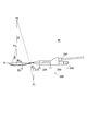
- FIG. 1 is a perspective view of a lacrimal duct endoscope 10 according to the embodiment.
- FIG. 2 is a side view of the lacrimal duct endoscope 10 according to the embodiment.
- FIG. 3A is a view showing a distal end 100b surface of the insertion portion 100 of the lacrimal duct endoscope 10 according to the embodiment, and
- FIG. 3B is a sectional view taken along line IIIb-IIIb in FIG.
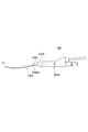
- FIG. 4 is an enlarged view of a main part in a side view of the lacrimal duct endoscope 10 according to the embodiment.
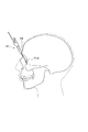
- FIG. 5 is a diagram showing a state in which the lacrimal duct endoscope 10 according to the embodiment is inserted into the lacrimal duct.
- FIG. 6 is a side view of a lacrimal duct endoscope 10 according to another embodiment.
- FIG. 1 is a perspective view of a lacrimal duct endoscope 10 according to an embodiment of the present invention.
- FIG. 2 is a side view thereof.
- the lacrimal duct endoscope 10 includes a tubular insertion portion 100 that is inserted into the lacrimal passage and a base portion 200 to which a proximal end 100 a of the insertion portion 100 is attached.
- FIG. 3A is a view of the front end surface 100b of the insertion part 100 as seen from the vertical direction
- FIG. 3B is a view showing the insertion part 100 along the line IIIb-IIIb in FIG.
- FIG. 5 is an enlarged cross-sectional view when cut perpendicular to the central axis of 300.
- the lacrimal duct endoscope 10 includes a rigid insertion portion 100. As shown in FIGS. 3A and 3B, the insertion portion 100 is covered with an outer tube 300 that covers the outer peripheral surface.
- the outer tube 300 is made of metal such as stainless steel. However, the material of the outer tube 300 may be hard plastic, metal, or a composite material thereof.
- an objective lens 310 that serves as an observation window at the time of photographing, optical fiber tube bundles 320 and 330, and a channel 340 for ventilation and / or water passage are provided.
- the optical fiber tube bundles 320 and 330 include an image guide fiber 320 that transmits a captured image to an imaging system (not shown), and a light guide fiber 330 that conducts light from a light source (not shown) to illuminate an object to be captured. including.
- the ventilation and / or water-passage channel 340 is provided to ventilate the lacrimal passage or to pass physiological saline or the like as necessary when the lacrimal endoscope 10 is inserted or when the inside of the lacrimal endoscope 10 is imaged. Is the channel of.
- the base 200 includes a support portion 210, a grip portion 220, and a connecting portion 230.
- the base portion 200 is a metal casing (body), and the optical fiber tube bundles 320 and 330 and the ventilation and / or water passage channels 340 are housed inside the base portion 200.
- Stainless steel is preferably used for the housing forming the base 200, but other relatively hard plastics, metals, or composite materials thereof may be used.
- the grip portion 220 has a tubular shape. Specifically, the grip portion 220 has a substantially cylindrical shape.
- the grip portion 220 is a portion that is gripped by a user's hand when operating the lacrimal duct endoscope 10.
- the central axis CL of the grip portion 220 extends parallel to the longitudinal direction of the base 200.
- the central axis line of the base portion 200 means the central axis line CL of the grip portion 220.
- the grip portion 220 has a substantially cylindrical shape in the present embodiment, the grip portion 220 is not limited to this as long as the grip portion 220 has a cylindrical shape.
- the grip portion 220 may have a polygonal prism shape, a truncated cone shape, or the like.
- the support portion 210 is continuous with the base end 100a of the insertion portion 100 at one end in the longitudinal direction of the base portion 200.
- the support portion 210 is connected to the grip portion 220 at the other end in the longitudinal direction of the base portion 200.
- the support portion 210 has a tapered shape in which the outer diameter is reduced from the grip portion 220 side to the insertion portion 100 side at a constant gradient in the longitudinal direction of the base portion 200.
- An end surface 210b perpendicular to the longitudinal direction of the base 200 is formed at the end of the insertion section 100 that is continuous with the base end 100a.
- the support portion 210 coaxially supports the first linear portion 110 (see FIG. 4) of the insertion portion 100.
- the connecting portion 230 is continuous with the grip portion 220, and has a width wider than that of the grip portion 220 along the direction orthogonal to the central axis CL so that the ventilation and / or water passage lure port 240 and the unicode portion 250 can be connected. Is.
- the ventilation and / or water passage lure port 240 is a connection port for supplying air or physiological saline or the like from a supply source to the ventilation and / or water passage channel 340 of the insertion portion 100.
- the Unicode part 250 includes the optical fiber tube bundles 320 and 330 extending from the insertion part 100 and covers the optical fiber tube bundles 320 and 330.
- the Unicode section 250 is connected to the imaging system light source.
- FIG. 4 is an enlarged view of an essential part showing details of the insertion portion 100 in the side view of the lacrimal duct endoscope 10 according to the present embodiment.
- the insertion portion 100 includes a first linear portion 110 that extends vertically from the end surface 210 b of the support portion 210, a second linear portion 120 located at the tip of the insertion portion 100, and a first linear portion 110.
- the curved portion 130 is formed between the second straight portion 120 and the curved portion 130.
- the total length of the insertion part 100 is set to about 60 mm.
- the first straight portion 110 is continuous with the end surface 210b of the support portion 210 and extends along the central axis CL of the grip portion 220.
- the curved portion 130 has one end connected to the first linear portion 110, and the other end located on the distal end 100b side of the insertion portion 100 connected to the second linear portion 120.
- the curved portion 130 is curved with respect to the central axis CL of the grip portion 220 in a first curved portion 140 that is curved in a first direction that is perpendicular to the longitudinal direction of the base 200, and is curved in a second direction that is opposite to the first direction. And a second curved portion 150.
- the second curved portion 150 is formed closer to the distal end 100b side of the insertion portion 100 than the first curved portion 140.
- the bending of the first curved portion 140 and the second curved portion 150 causes the optical fiber tube bundles 320 and 330 and the ventilation and / or water passage channels 340 provided in the insertion portion 100. It is curved and extends toward the distal end 100b of the insertion portion 100.
- the center of curvature P1 of the first bending portion 140 is located on the side of the central axis CL of the grip portion 220 in the first direction perpendicular to the central axis CL of the grip portion 220.
- the first bending portion 140 has an arc shape with a radius of curvature R1 of 30 mm, and is bent in the first direction from the central axis CL of the grip portion 220.
- the centers of curvature P2 and P3 of the second bending portion 150 are located on the side in the second direction that is the side opposite to the first direction with respect to the insertion portion 100.
- the second direction is the direction of the Unicode portion 250 with respect to the central axis line CL of the grip portion 220.
- the second curved portion 150 includes a small curved region 170 having a predetermined radius of curvature R2 at the center of curvature P2 and a large curved region 160 having a radius of curvature R3 smaller than the predetermined radius of curvature R2 at the center of curvature P3.
- the small curved region 170 has an arc shape with a radius of curvature R2 of 140 mm
- the large curved region 160 has an arc shape with a radius of curvature R3 of 44 mm.
- the large bending region 160 is formed closer to the distal end 100b side of the insertion section 100 than the small bending region 170.
- the end portion of the second curved portion 150 which is continuous with the second straight portion 120 is bent in the second direction with respect to the longitudinal direction of the base portion 200.
- the radius of curvature R1 of the first curved portion 140 is smaller than the radii of curvature R2 and R3 of the curved regions 170 and 160 in the second curved portion.
- FIG. 5 is a diagram showing a state in which the lacrimal duct endoscope 10 is inserted into the lacrimal duct. Specifically, FIG. 5 shows a state in which the insertion portion 100 is inserted into the nasolacrimal duct from the lacrimal fossa FLS.
- the insertion portion 100 has a shape that includes a first curved portion 140 that is curved in the first direction and a second curved portion 150 that is curved in the opposite side to the first direction. According to the shape of the insertion portion 100, even when the lacrimal endoscope 10 is operated with the insertion portion 100 inserted in the nasolacrimal duct, the insertion portion 100 and the base portion 200 interfere with the frontal bone FB. It gets harder. As a result, it is possible to perform the same operation on a patient in the back as it is not affected by the position through which the nasolacrimal duct passes.
- the bending direction of the second bending portion 150 is the direction of the unicode portion 250 with respect to the central axis CL of the grip portion 220. Therefore, even when the insertion portion 100 is inserted in the nasolacrimal duct, the unicode portion 250 hardly interferes with the frontal bone FB.
- the longitudinal direction of the base portion 200 is close to the insertion direction of the insertion portion 100 when the insertion portion 100 is inserted into the nasolacrimal duct. Therefore, the operability of the lacrimal duct endoscope 10 is improved, and the insertion operation of the lacrimal duct endoscope 10 can be easily performed. Further, it is possible to suppress the deformation of the insertion portion 100 due to an excessive force applied to the lacrimal duct endoscope 10 during the insertion operation.
- the configuration of the present embodiment has a conventional configuration, such as a case where a patient is deeply carved or has a carapace and the base portion 200 hits the edge of the orbit of the patient, that is, the eyebrow, so that the insertion portion 100 cannot be inserted into the lacrimal passage. This is more effective when it is difficult to guide the insertion portion 100 to the nasolacrimal duct.
- the radius of curvature R1 of the first curved portion 140 is smaller than the radii of curvature R2 and R3 of the second curved portion 150. Therefore, the insertion section 100 and the base section 200 are less likely to interfere with the frontal bone FB.
- the large bending region 160 is formed closer to the distal end 100b side of the insertion section 100 than the small bending region 170. Therefore, when the lacrimal duct endoscope 10 is inserted into the lacrimal duct, it is possible to easily guide the insertion portion 100 into the nasolacrimal duct through the bent lacrimal canaliculus from the lacrimal point.
- the distal end 100b of the insertion portion 100 is located on the first direction side with respect to the central axis CL of the grip portion 220 of the base portion 200. Therefore, in the operation of inserting the insertion portion 100 into the lacrimal passage, the base portion 200 is less likely to interfere with the frontal bone FB.
- the first curved portion 140 is formed so as to be continuous with the first linear portion 110 of the insertion portion 100.
- the arrangement of the first curved portion 140 is not limited to this.
- the shape of the support portion 210 is a taper shape in which the outer diameter is reduced from the grip portion 220 side to the insertion portion 100 side with a constant gradient in the longitudinal direction of the base portion 200.
- the shape of the support portion 210 is not limited to this.
- it may have a cylindrical shape that extends from the grip portion 220 side to the insertion portion 100 side with a constant outer shape.
- FIG. 6 is a modified example showing the lacrimal duct endoscope 10A in which the first curved portion 140A is formed on the base portion 200A.
- the support portion 210A is bent in the first direction from the central axis of the base 200A (the central axis CL of the grip 220).
- the optical fiber tube bundles 320 and 330 and the ventilation and / or water passage channels 340 of the first curved portion 140A are arranged in the base portion 200A (support portion 210A) similarly to the first curved portion 140 of the above-described embodiment. It bends in one direction.
- the base portion 200A is bent in the first direction, and the optical fiber tube bundles 320, 330 passing therethrough and the ventilation and / or water passage channels 340 are arranged in a straight line. You may.
- the base 200A is formed such that the end surface 210Ab of the support portion 210A forms a predetermined angle with the central axis CL of the grip portion 220.
- the insertion portion 100A extends substantially vertically from the center of the end surface 210Ab of the support portion 210A, and is connected to the second bending portion 150 on the distal end side.
- the first curved portion 140A is protected by the support portion 210A, according to the lacrimal duct endoscope 10A according to the modified example, even when a load is applied to the lacrimal duct endoscope 10A, the first curved portion 140A is protected. Plastic deformation is suppressed and the curved shape is maintained.
- 10A lacrimal endoscope 100 100A insertion part 100a base end 100b tip 110 first straight part 120 second straight part 130 curved part 140, 140A first curved part 150 second curved part 160 large curved region 170 small curved region 200,200A
- Base part 210,210A Support part 220 Grip part 230 Connection part 240 Ventilation and / or water passage lure mouth 250 Unicode part 300
- Outer tube 310 Objective lens 320 Image guide fiber 330 Light guide fiber 340 Channel CL central axis FLS tear Capsule FB Frontal bone
Landscapes
- Health & Medical Sciences (AREA)
- Life Sciences & Earth Sciences (AREA)
- Surgery (AREA)
- General Health & Medical Sciences (AREA)
- Public Health (AREA)
- Biomedical Technology (AREA)
- Heart & Thoracic Surgery (AREA)
- Veterinary Medicine (AREA)
- Engineering & Computer Science (AREA)
- Animal Behavior & Ethology (AREA)
- Nuclear Medicine, Radiotherapy & Molecular Imaging (AREA)
- Ophthalmology & Optometry (AREA)
- Physics & Mathematics (AREA)
- Biophysics (AREA)
- Optics & Photonics (AREA)
- Pathology (AREA)
- Radiology & Medical Imaging (AREA)
- Medical Informatics (AREA)
- Molecular Biology (AREA)
- Vascular Medicine (AREA)
- Otolaryngology (AREA)
- Endoscopes (AREA)
Abstract
涙道内視鏡(10)は、涙道に挿入される管状の挿入部(100)と、挿入部(100)の基端(100a)が取り付けられる基部(200)とを備える。涙道内視鏡(10)は、第1方向に曲がった第1湾曲部分(140)と、第1方向と反対側である第2方向に曲がった第2湾曲部分(150)とを含む。第1湾曲部分(140)は、挿入部(100)または基部(200)に形成され、第2湾曲部分(150)は、第1湾曲部分(140)よりも挿入部(100)の先端(100b)側に形成される。
Description
本発明は、涙道内視鏡に関する。
涙道内腔の観察、診断、撮影または治療などに用いる硬性涙道鏡として、涙道内視鏡が知られている。涙道内視鏡は、涙道に挿入される硬性の挿入部を備え、管状の挿入部内には、光ファイバ管束及び通水用のチャネルなどが備えられる。
挿入部の基端は、涙道内視鏡の使用者の手で把持される基部(ボディ)に取り付けられている。
また、このような涙道内視鏡の挿入部は、涙道への挿入を容易にするため、一部が湾曲した形状を有していることが一般的である(特許文献1参照)。
しかしながら、上述した従来の涙道内視鏡には、次のような問題がある。具体的には、挿入部を涙道に挿入する際に、基部が患者の眼窩上部と干渉し、挿入部を涙道に適切に挿入できない場合がある。
具体的には、基部が患者の眼窩の縁(眉の辺り)に当たってしまい、挿入部を涙道に挿入できない現象が確認されている。特に、彫りが深い、或いは奧目の患者では、このような現象が生じ易い。
加えて、鼻涙管が頭蓋骨寄りに通っている患者の場合にも、基部が患者の眼窩の縁に当たってしまい、挿入部を涙道に挿入できない現象や奥目でない患者と同等の操作ができない現象が確認されている。
そこで、本発明は、このような状況に鑑みてなされたものであり、基部が患者の眼窩上部と干渉することなく、挿入部を涙道に適切に挿入し得る涙道内視鏡の提供を目的とする。
本発明の実施形態に係る涙道内視鏡は、涙道に挿入される管状の挿入部と、挿入部の基端が取り付けられる基部とを備える。涙道内視鏡は、第1方向に曲がった第1湾曲部分と、第1方向と反対側である第2方向に曲がった第2湾曲部分と含む。第1湾曲部分は、挿入部または基部に形成される。第2湾曲部分は、第1湾曲部分よりも挿入部の先端側に形成される。
上述の構成に係る涙道内視鏡は、第1方向に曲がった第1湾曲部分と、第1方向と反対側に曲がった第2湾曲部分とを含む。このため、彫りが深い或いは奥目の患者であっても前記基部を患者の眼窩上部に干渉させることなく前記挿入部を涙道に適切に挿入し得る。
以下、実施形態を図面に基づいて説明する。なお、同一の機能や構成には、同一または類似の符号を付して、その説明を適宜省略する。
(1)涙道内視鏡の全体概略構成
図1は、本発明の実施形態に係る涙道内視鏡10の斜視図である。図2は、その側面図である。
図1は、本発明の実施形態に係る涙道内視鏡10の斜視図である。図2は、その側面図である。
図1、図2に示すように、涙道内視鏡10は、涙道に挿入される管状の挿入部100と、挿入部100の基端100aが取り付けられる基部200とを備える。
図3(a)は、挿入部100の先端100bを、垂直な方向から見た先端面の図であり、図3(b)は、図2中のIIIb-IIIb線で挿入部100を外装管300の中心軸に対して垂直に切断したときの拡大横断面図である。
涙道内視鏡10は、硬性の挿入部100を備える。図3(a),図3(b)に示すように、挿入部100は、外周面を覆う外装管300で覆われている。外装管300は、ステンレス鋼等の金属で構成されている。ただし、外装管300の材料は、硬質なプラスチック、金属、またはそれらの複合材料を用いてもよい。
管状の挿入部100内には、撮影の際に観察窓となる対物レンズ310、光ファイバ管束320,330、及び通気用及び/又は通水用のチャネル340が設けられている。光ファイバ管束320,330は、撮影した画像をイメージングシステム(不図示)まで伝送するイメージガイドファイバー320と、撮影対象を照明するために光源(不図示)からの光を導通するライトガイドファイバー330とを含む。通気用及び/又は通水用のチャネル340は、涙道内視鏡10の挿入する際、あるいは内部を撮影する際に必要に応じて涙道に通気する、あるいは生理食塩水等を通水するためのチャネルである。
図2に示すように、基部200は、支持部分210、把持部分220、接続部分230を含む。基部200は、金属製の筐体(ボディ)であり、基部200の内部には、光ファイバ管束320,330、及び通気用及び/又は通水用のチャネル340が収容される。
基部200を構成する筐体としては、ステンレス鋼(SUS)が好適に用いられるが、それ以外の比較的硬質なプラスチック、金属またはそれらの複合材を用いてもよい。
図1に示すように、把持部分220は筒状である。具体的に、把持部分220は、略円筒状である。把持部分220は、涙道内視鏡10を操作する際、使用者の手で把持される部分である。把持部分220の中心軸線CLは、基部200の長手方向と平行に延びている。本明細書において、基部200の中軸線とは、把持部分220の中心軸線CLを意味する。なお、本実施形態において把持部分220は略円筒状であったが、把持部分220が筒状の形状である限り、これに限定されるものではない。例えば、把持部分220は、多角柱状、円錐台状等であってもよい。
支持部分210は、基部200の長手方向における一端で挿入部100の基端100aに連なる。支持部分210は、基部200の長手方向における他端で把持部分220に連なる。支持部分210は、基部200の長手方向において、把持部分220側から挿入部100側に一定の勾配で外径が縮小するテーパ状である。挿入部100の基端100aと連なる端部には、基部200の長手方向に垂直な端面210bが形成されている。支持部分210は、挿入部100の第1直線部分110(図4参照)を同軸状に支持する。
接続部分230は、把持部分220に連なり、通気用及び/又は通水用ルアー口240及びユニコード部250が接続できるように、中心軸線CLに直交する方向に沿った幅が把持部分220よりも幅広である。
通気用及び/又は通水用ルアー口240は、挿入部100の通気用及び/又は通水用のチャネル340に供給源からの空気或いは生理食塩水等を供給するための接続口である。
ユニコード部250は、挿入部100から延びる光ファイバ管束320,330を含み、光ファイバ管束320,330を被覆する。ユニコード部250は、イメージングシステム光源に接続される。
(2)挿入部の形状
図4は、本実施形態に係る涙道内視鏡10の側面図における挿入部100の詳細を示した要部拡大図である。
図4は、本実施形態に係る涙道内視鏡10の側面図における挿入部100の詳細を示した要部拡大図である。
図4に示すように、挿入部100は、支持部分210の端面210bから垂直に延びる第1直線部分110と、挿入部100の先端に位置する第2直線部分120と、第1直線部分110と第2直線部分120との間に形成される曲線部分130を含む。なお、本実施形態において、挿入部100の全長は約60mmに設定されている。
第1直線部分110は、支持部分210の端面210bに連なり、把持部分220の中心軸線CLに沿って延びている。曲線部分130は、基部200の長手方向において、一端が第1直線部分110に連なり、挿入部100の先端100b側に位置する他端が第2直線部分120に連なる。
曲線部分130は、把持部分220の中心軸線CLに対して、基部200の長手方向に垂直な第1方向に曲がった第1湾曲部分140と、第1方向と反対側である第2方向に曲がった第2湾曲部分150とを含む。本実施形態では、第2湾曲部分150は、第1湾曲部分140よりも挿入部100の先端100b側に形成されている。
なお、本実施形態において、第1湾曲部分140および第2湾曲部分150が曲がることで、挿入部100内に設けられた光ファイバ管束320,330及び通気用及び/又は通水用のチャネル340が湾曲して、挿入部100の先端100b側に延びている。
本実施形態では、第1湾曲部140の曲率中心P1が、把持部分220の中心軸線CLに対して、把持部分220の中心軸線CLに垂直な第1方向の側に位置している。具体的には、第1湾曲部140は、曲率半径R1が30mmの円弧状であり、把持部分220の中心軸線CLから第1方向に曲がっている。
本実施形態では、第2湾曲部150の曲率中心P2,P3が、挿入部100に対して、第1方向と反対側である第2方向の側に位置している。具体的には、第2方向は把持部分220の中心軸線CLに対するユニコード部250の方向とされている。第2湾曲部150は、曲率中心P2で所定の曲率半径R2を有する小湾曲領域170と、曲率中心P3で所定の曲率半径R2よりも小さい曲率半径R3を有する大湾曲領域160とを含む。具体的には、小湾曲領域170は、曲率半径R2が140mmの円弧状であり、大湾曲領域160は、曲率半径R3が44mmの円弧状である。大湾曲領域160は、小湾曲領域170よりも挿入部100の先端100b側に形成される。第2湾曲部150の第2直線部分120に連なる端部は、基部200の長手方向に対して第2方向に曲がっている。
第1湾曲部分140の曲率半径R1は、第2湾曲部分における湾曲領域170,160の曲率半径R2,R3のよりも小さい。
(3)作用・効果
図5は、涙道内視鏡10を涙道に挿入した状態を示す図である。具体的に、図5は、涙嚢窩FLSから鼻涙管内に挿入部100が挿入された状態を示す。
図5は、涙道内視鏡10を涙道に挿入した状態を示す図である。具体的に、図5は、涙嚢窩FLSから鼻涙管内に挿入部100が挿入された状態を示す。
本実施形態では、挿入部分100が第1方向に曲がった第1湾曲部分140と、第1方向と反対側に曲がった第2湾曲部分150とを含む形状を有する。この挿入部分100の形状によれば、鼻涙管に挿入部100が挿入された状態で涙道内視鏡10を操作した場合であっても、挿入部100及び基部200が前頭骨FBに干渉し難くなる。これにより、奥目の患者に対しても、鼻涙管が通る位置に左右されない奥目でない患者と同等の操作が可能となる。
本実施形態では、第2湾曲部分150の湾曲方向は把持部分220の中心軸線CLに対するユニコード部250の方向とされている。このため、鼻涙管に挿入部100が挿入された状態であっても、ユニコード部250が前頭骨FBに干渉し難くなる。
また、本実施形態では、鼻涙管に挿入部100が挿入された状態において、基部200の長手方向が挿入部100の挿入方向と近い角度になる。このため、涙道内視鏡10の操作性が向上し、涙道内視鏡10の挿入操作を容易に行うことができる。さらに、挿入操作時に涙道内視鏡10に無理な力がかかることによる挿入部100の変形を抑制することができる。
本実施形態の構成は、特に彫りが深い或いは奧目の患者で基部200が患者の眼窩の縁、つまり眉の辺りに当たってしまうことで挿入部100を涙道に挿入できない場合等、従来の構成では鼻涙管へ挿入部100を導くこと自体が困難な場合により効果的である。
本実施形態では、第1湾曲部分140の曲率半径R1が、第2湾曲部分150の曲率半径R2,R3よりも小さくなっている。このため、挿入部100及び基部200が前頭骨FBにさらに干渉し難くなっている。
本実施形態では、大湾曲領域160は、小湾曲領域170よりも挿入部100の先端100b側に形成されている。このため、涙道内視鏡10を涙道に挿入する際、涙点から屈曲した涙小管を通り、鼻涙管への挿入部100を容易に導くことができる。
本実施形態では、挿入部100の先端100bは、基部200における把持部220の中心軸線CLよりも第1方向側に位置している。このため、涙道に挿入部100を挿入する操作において、基部200が前頭骨FBにさらに干渉し難くなっている。
(4)その他の実施形態
以上、実施例に沿って本発明の内容を説明したが、本発明はこれらの記載に限定されるものではなく、種々の変形及び改良が可能であることは、当業者には自明である。
以上、実施例に沿って本発明の内容を説明したが、本発明はこれらの記載に限定されるものではなく、種々の変形及び改良が可能であることは、当業者には自明である。
例えば、上記実施形態では、第1湾曲部分140が、挿入部100の第1直線部分110に連なって形成されていた。しかし、第1湾曲部分140の配置はこれに限定されるものではない。
また、上記実施形態では、支持部分210の形状は基部200の長手方向において、把持部分220側から、挿入部100側に一定の勾配で外径が縮小するテーパ状とされていた。しかし、支持部分210の形状はこれに限るものではない。例えば、把持部分220側から、挿入部100側に一定の外形で延出する円柱状とされていても良い。
図6は、第1湾曲部分140Aが基部200Aに形成された涙道内視鏡10Aを示す変形例である。変形例において、支持部分210Aは、基部200Aの中軸線(把持部220の中心軸線CL)から第1方向に曲がっている。第1湾曲部分140Aの光ファイバ管束320,330及び通気用及び/又は通水用のチャネル340は、基部200A(支持部分210A)内で、上記実施形態の第1湾曲部140と同様に、第1方向に曲がっている。ただし、第1湾曲部分140Aは、基部200Aが第1方向に曲がっていればよく、内部を通る光ファイバ管束320,330及び通気用及び/又は通水用のチャネル340は、直線状に配置されてもよい。基部200Aは、支持部分210Aの端面210Abが把持部分220の中心軸線CLと所定の角度を成して形成されている。挿入部100Aは、支持部分210Aの端面210Abの中心から略垂直に延びており、先端側で第2湾曲部150と連なっている。
第1湾曲部分140Aの少なくとも一部が支持部分210Aで保護されるため、変形例に係る涙道内視鏡10Aによれば、涙道内視鏡10Aに負荷が掛かった場合でも第1湾曲部分140Aの塑性変形が抑制され、湾曲形状が維持される。
上記のように、本発明の実施形態を記載したが、この開示の一部をなす論述及び図面はこの発明を限定するものであると理解すべきではない。この開示から当業者には様々な代替実施の形態、実施例及び運用技術が明らかとなろう。
特願2018-215006号(出願日:2018年11月15日)の全内容は、ここに援用される。
10,10A 涙道内視鏡
100,100A 挿入部
100a 基端
100b 先端
110 第1直線部
120 第2直線部
130 曲線部分
140,140A 第1湾曲部
150 第2湾曲部
160 大湾曲領域
170 小湾曲領域
200,200A 基部
210,210A 支持部分
220 把持部分
230 接続部分
240 通気用及び/又は通水用ルアー口
250 ユニコード部
300 外装管
310 対物レンズ
320 イメージガイドファイバー
330 ライトガイドファイバー
340 チャンネル
CL 中心軸線
FLS 涙嚢窩
FB 前頭骨
100,100A 挿入部
100a 基端
100b 先端
110 第1直線部
120 第2直線部
130 曲線部分
140,140A 第1湾曲部
150 第2湾曲部
160 大湾曲領域
170 小湾曲領域
200,200A 基部
210,210A 支持部分
220 把持部分
230 接続部分
240 通気用及び/又は通水用ルアー口
250 ユニコード部
300 外装管
310 対物レンズ
320 イメージガイドファイバー
330 ライトガイドファイバー
340 チャンネル
CL 中心軸線
FLS 涙嚢窩
FB 前頭骨
Claims (6)
- 涙道に挿入される管状の挿入部と、前記挿入部の基端が取り付けられる基部とを備える涙道内視鏡であって、
第1方向に曲がった第1湾曲部分と、
前記第1方向と反対側である第2方向に曲がった第2湾曲部分と
を含み、
前記第1湾曲部分は、前記挿入部または前記基部に形成され、
前記第2湾曲部分は、前記第1湾曲部分よりも前記挿入部の先端側に形成される涙道内視鏡。 - 前記基部にユニコードが接続され、
前記第2方向は前記基部の中軸線に対するユニコードの方向とされている請求項1に記載の涙道内視鏡。 - 前記第1湾曲部分の曲率半径は、前記第2湾曲部分の曲率半径よりも小さい請求項1または2に記載の涙道内視鏡。
- 前記第2湾曲部分は、
所定の曲率半径を有する小湾曲領域と、
前記所定の曲率半径よりも小さい曲率半径を有する大湾曲領域と
を含み、
前記大湾曲領域は、前記小湾曲領域よりも前記挿入部の先端側に形成される請求項1乃至3の何れか一項に記載の涙道内視鏡。 - 前記挿入部の先端は、前記基部の中軸線よりも前記第1方向側に位置する請求項1乃至4の何れか一項に記載の涙道内視鏡。
- 前記第1湾曲部分は、前記挿入部の基端側に形成され、
前記第1湾曲部分と前記基部との間には、直線部分が形成される請求項1乃至5の何れか一項に記載の涙道内視鏡。
Priority Applications (1)
| Application Number | Priority Date | Filing Date | Title |
|---|---|---|---|
| JP2020555695A JP7668112B2 (ja) | 2018-11-15 | 2019-11-12 | 涙道内視鏡 |
Applications Claiming Priority (2)
| Application Number | Priority Date | Filing Date | Title |
|---|---|---|---|
| JP2018215006 | 2018-11-15 | ||
| JP2018-215006 | 2018-11-15 |
Publications (1)
| Publication Number | Publication Date |
|---|---|
| WO2020100844A1 true WO2020100844A1 (ja) | 2020-05-22 |
Family
ID=70730256
Family Applications (1)
| Application Number | Title | Priority Date | Filing Date |
|---|---|---|---|
| PCT/JP2019/044216 Ceased WO2020100844A1 (ja) | 2018-11-15 | 2019-11-12 | 涙道内視鏡 |
Country Status (2)
| Country | Link |
|---|---|
| JP (1) | JP7668112B2 (ja) |
| WO (1) | WO2020100844A1 (ja) |
Cited By (1)
| Publication number | Priority date | Publication date | Assignee | Title |
|---|---|---|---|---|
| JP2022119243A (ja) * | 2021-02-04 | 2022-08-17 | ニプロ株式会社 | 涙道内視鏡 |
Citations (7)
| Publication number | Priority date | Publication date | Assignee | Title |
|---|---|---|---|---|
| JP2001087212A (ja) * | 1999-09-21 | 2001-04-03 | Olympus Optical Co Ltd | 硬性鏡 |
| JP2001327525A (ja) * | 2000-03-14 | 2001-11-27 | Nakagawa Akio | 涙道再形成手術に用いる鼻涙管チューブおよび鼻涙管チューブ器具 |
| JP2009044799A (ja) * | 2007-08-06 | 2009-02-26 | Jtekt Corp | ブラシレスモータ |
| JP2009268523A (ja) * | 2008-04-30 | 2009-11-19 | Olympus Medical Systems Corp | 内視鏡 |
| WO2015114995A1 (ja) * | 2014-01-29 | 2015-08-06 | オリンパス株式会社 | 前立腺生検用膀胱尿道鏡及び処置具 |
| JP2016209448A (ja) * | 2015-05-13 | 2016-12-15 | ファイバーテック株式会社 | 涙道内視鏡 |
| JP2018512194A (ja) * | 2015-03-16 | 2018-05-17 | ドゥエプントゼーロ エス.アール.エル. | 気管挿管のための装置 |
-
2019
- 2019-11-12 WO PCT/JP2019/044216 patent/WO2020100844A1/ja not_active Ceased
- 2019-11-12 JP JP2020555695A patent/JP7668112B2/ja active Active
Patent Citations (7)
| Publication number | Priority date | Publication date | Assignee | Title |
|---|---|---|---|---|
| JP2001087212A (ja) * | 1999-09-21 | 2001-04-03 | Olympus Optical Co Ltd | 硬性鏡 |
| JP2001327525A (ja) * | 2000-03-14 | 2001-11-27 | Nakagawa Akio | 涙道再形成手術に用いる鼻涙管チューブおよび鼻涙管チューブ器具 |
| JP2009044799A (ja) * | 2007-08-06 | 2009-02-26 | Jtekt Corp | ブラシレスモータ |
| JP2009268523A (ja) * | 2008-04-30 | 2009-11-19 | Olympus Medical Systems Corp | 内視鏡 |
| WO2015114995A1 (ja) * | 2014-01-29 | 2015-08-06 | オリンパス株式会社 | 前立腺生検用膀胱尿道鏡及び処置具 |
| JP2018512194A (ja) * | 2015-03-16 | 2018-05-17 | ドゥエプントゼーロ エス.アール.エル. | 気管挿管のための装置 |
| JP2016209448A (ja) * | 2015-05-13 | 2016-12-15 | ファイバーテック株式会社 | 涙道内視鏡 |
Cited By (2)
| Publication number | Priority date | Publication date | Assignee | Title |
|---|---|---|---|---|
| JP2022119243A (ja) * | 2021-02-04 | 2022-08-17 | ニプロ株式会社 | 涙道内視鏡 |
| JP7639375B2 (ja) | 2021-02-04 | 2025-03-05 | ニプロ株式会社 | 涙道内視鏡 |
Also Published As
| Publication number | Publication date |
|---|---|
| JP7668112B2 (ja) | 2025-04-24 |
| JPWO2020100844A1 (ja) | 2021-10-07 |
Similar Documents
| Publication | Publication Date | Title |
|---|---|---|
| JP5993535B2 (ja) | 内視鏡用湾曲部及びこの内視鏡用湾曲部を具備した内視鏡 | |
| US20110060190A1 (en) | Laryngoscope apparatus with enhanced viewing capability | |
| JP2006280602A (ja) | 内視鏡 | |
| US8317683B2 (en) | Endoscope | |
| JP7668112B2 (ja) | 涙道内視鏡 | |
| KR20190049306A (ko) | 관절용 내시경 | |
| JP4124423B2 (ja) | 涙道内視鏡 | |
| JP6522258B2 (ja) | 挿入補助システム | |
| JP6236410B2 (ja) | 涙道内視鏡 | |
| JP7609078B2 (ja) | 涙道内視鏡 | |
| JP6180449B2 (ja) | 硬性内視鏡 | |
| JP5283463B2 (ja) | 内視鏡 | |
| JPH07100096A (ja) | 内視鏡装置 | |
| JP5462135B2 (ja) | 内視鏡 | |
| JP7639375B2 (ja) | 涙道内視鏡 | |
| JP6899316B2 (ja) | 涙道内視鏡 | |
| WO2016035393A1 (ja) | 内視鏡 | |
| JP2018175868A (ja) | 内視鏡プローブ | |
| KR20190049307A (ko) | 관절용 내시경 | |
| JP4071058B2 (ja) | 内視鏡のフード構造 | |
| JP2023158298A (ja) | 涙道内視鏡、及び補強部材 | |
| JP5231078B2 (ja) | 内視鏡 | |
| JP2004041430A (ja) | 内視鏡の先端部構造 | |
| JP2004337377A (ja) | 極細径内視鏡 | |
| JPH0719441Y2 (ja) | 硬性内視鏡 |
Legal Events
| Date | Code | Title | Description |
|---|---|---|---|
| 121 | Ep: the epo has been informed by wipo that ep was designated in this application |
Ref document number: 19885479 Country of ref document: EP Kind code of ref document: A1 |
|
| ENP | Entry into the national phase |
Ref document number: 2020555695 Country of ref document: JP Kind code of ref document: A |
|
| NENP | Non-entry into the national phase |
Ref country code: DE |
|
| 122 | Ep: pct application non-entry in european phase |
Ref document number: 19885479 Country of ref document: EP Kind code of ref document: A1 |