WO2020100665A1 - 自動変速機の制御装置 - Google Patents
自動変速機の制御装置 Download PDFInfo
- Publication number
- WO2020100665A1 WO2020100665A1 PCT/JP2019/043365 JP2019043365W WO2020100665A1 WO 2020100665 A1 WO2020100665 A1 WO 2020100665A1 JP 2019043365 W JP2019043365 W JP 2019043365W WO 2020100665 A1 WO2020100665 A1 WO 2020100665A1
- Authority
- WO
- WIPO (PCT)
- Prior art keywords
- lubrication
- solenoid
- shift
- automatic transmission
- friction element
- Prior art date
- Legal status (The legal status is an assumption and is not a legal conclusion. Google has not performed a legal analysis and makes no representation as to the accuracy of the status listed.)
- Ceased
Links
Images




Classifications
-
- F—MECHANICAL ENGINEERING; LIGHTING; HEATING; WEAPONS; BLASTING
- F16—ENGINEERING ELEMENTS AND UNITS; GENERAL MEASURES FOR PRODUCING AND MAINTAINING EFFECTIVE FUNCTIONING OF MACHINES OR INSTALLATIONS; THERMAL INSULATION IN GENERAL
- F16H—GEARING
- F16H59/00—Control inputs to control units of change-speed- or reversing-gearings for conveying rotary motion
- F16H59/68—Inputs being a function of gearing status
-
- F—MECHANICAL ENGINEERING; LIGHTING; HEATING; WEAPONS; BLASTING
- F16—ENGINEERING ELEMENTS AND UNITS; GENERAL MEASURES FOR PRODUCING AND MAINTAINING EFFECTIVE FUNCTIONING OF MACHINES OR INSTALLATIONS; THERMAL INSULATION IN GENERAL
- F16H—GEARING
- F16H61/00—Control functions within control units of change-speed- or reversing-gearings for conveying rotary motion ; Control of exclusively fluid gearing, friction gearing, gearings with endless flexible members or other particular types of gearing
- F16H61/12—Detecting malfunction or potential malfunction, e.g. fail safe ; Circumventing or fixing failures
-
- F—MECHANICAL ENGINEERING; LIGHTING; HEATING; WEAPONS; BLASTING
- F16—ENGINEERING ELEMENTS AND UNITS; GENERAL MEASURES FOR PRODUCING AND MAINTAINING EFFECTIVE FUNCTIONING OF MACHINES OR INSTALLATIONS; THERMAL INSULATION IN GENERAL
- F16H—GEARING
- F16H61/00—Control functions within control units of change-speed- or reversing-gearings for conveying rotary motion ; Control of exclusively fluid gearing, friction gearing, gearings with endless flexible members or other particular types of gearing
- F16H61/16—Inhibiting or initiating shift during unfavourable conditions , e.g. preventing forward-reverse shift at high vehicle speed, preventing engine overspeed
Definitions
- the present invention relates to a control device for an automatic transmission mounted on a vehicle.
- the hydraulic control circuit supplies the oil supplied from the first oil pump to the cooling oil passage, the lubricating oil passage, and the clutch oil passage.
- the hydraulic control circuit includes a regulator valve, two solenoid valves, two shift valves and a relief valve.
- the regulator valve is switched by a solenoid, and the second shift valve and the relief valve are switched by a solenoid.
- An oil temperature sensor is provided in each of the electric motor, the clutch oil passage, and the oil pan. The ECU detects a valve failure based on the output values of these sensors.
- the present invention was made in view of the above problems, and it is an object of the present invention to suppress an increase in heat load of a friction element without giving an occupant a feeling of discomfort when a lubrication solenoid fails.
- a control device for an automatic transmission includes, as one aspect thereof, an automatic transmission, a control valve unit, and a transmission control unit.
- the hydraulic control circuit of the control valve unit has a lubrication solenoid that regulates the lubricating flow rate supplied to the friction element to an appropriate flow rate that suppresses heat generation.
- the transmission control unit has a friction element temperature estimation unit that estimates the friction element temperature from the heat generation amount and the heat radiation amount, and a fail-safe control unit that takes measures against the failure mode of the lubricating solenoid.
- the friction element temperature estimation unit replaces the estimated heat radiation amount in continuous shift protection with the heat radiation amount during failure of the lubrication solenoid, and estimates the friction element temperature from the replaced heat radiation amount.
- the fail-safe control unit limits the shift by the automatic transmission when a failure of the lubrication solenoid is determined and the friction element estimated temperature from the friction element temperature estimation unit becomes equal to or higher than a predetermined temperature.
- the friction element temperature is estimated based on the estimated heat release amount in continuous shift protection, which is a high heat load shift pattern. Then, as a measure against heat of the friction element, a measure to limit the shift is adopted instead of a measure to limit the transmission input torque. As a result, when the lubrication solenoid fails, an increase in heat load on the friction element can be suppressed without giving an occupant an uncomfortable feeling.
- FIG. 1 is an overall system diagram showing an engine vehicle equipped with an automatic transmission to which the control device of the first embodiment is applied.
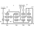
- FIG. 3 is a skeleton diagram showing an example of an automatic transmission to which the control device of the first embodiment is applied.
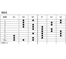
- FIG. 3 is an engagement table diagram showing an engagement state of a friction element for gear shifting in each gear in an automatic transmission to which the control device of the first embodiment is applied.
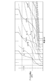
- FIG. 3 is a shift map diagram showing an example of a shift map in an automatic transmission to which the control device of the first embodiment is applied.
- 3 is a control system configuration diagram showing a detailed configuration of a control valve unit and an AT control unit of Embodiment 1.
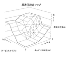
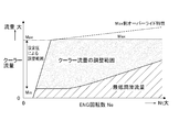
- FIG. 7 is a three-dimensional map diagram showing an example of a lubricating pressure setting map for searching a lubricating valve pressure instruction when the lubricating solenoid is normal.
- 6 is a flowchart showing a flow of fail-safe control processing executed when an electric failure occurs in a lubrication solenoid executed by a fail-safe control unit of the AT control unit according to the first embodiment. It is a time chart which shows each characteristic explaining a fail-safe control action at the time of an electric failure of a lubrication solenoid.
- the control device is applied to an engine vehicle (an example of a vehicle) equipped with an automatic transmission having a shift speed of 9 forward speeds and 1 reverse speed.
- an engine vehicle an example of a vehicle
- an automatic transmission having a shift speed of 9 forward speeds and 1 reverse speed.
- the configuration of the first embodiment will be divided into an “overall system configuration”, a “detailed configuration of an automatic transmission”, a “detailed configuration of a hydraulic / electronic control system”, and a “failsafe control processing configuration when a lubrication solenoid fails”. explain.
- FIG. 1 is an overall system diagram showing an engine vehicle equipped with an automatic transmission to which the control device of the first embodiment is applied. The overall system configuration will be described below with reference to FIG.
- the drive system of an engine vehicle includes an engine 1, a torque converter 2, an automatic transmission 3, a propeller shaft 4, and drive wheels 5.
- a control valve unit 6 including a spool valve for changing gears, a hydraulic control circuit, a solenoid valve, etc. is attached to the automatic transmission 3.
- the actuators (clutch solenoid 20, line pressure solenoid 21, lubrication solenoid 22, lockup solenoid 23) included in the control valve unit 6 operate upon receiving a control command from the AT control unit 10.
- a plurality of clutch solenoids 20 are provided for each friction element.
- the torque converter 2 incorporates a lock-up clutch 2a that directly connects the crank shaft of the engine 1 and the input shaft IN of the automatic transmission 3 when engaged.
- the control system of the engine car includes an AT control unit 10, an engine control unit 11, and a CAN communication line 12.
- the AT control unit 10 has a clutch temperature estimation unit 10a (friction element temperature estimation unit) and a fail-safe control unit 10b.
- the AT control unit 10 which is a control device of the automatic transmission 3, inputs signals from the turbine rotation sensor 13, the output shaft rotation sensor 14, the ATF oil temperature sensor 15, the inhibitor switch 18, the intermediate shaft rotation sensor 19, and the like.
- the ATF oil temperature sensor 15 detects the temperature of ATF (oil for automatic transmission) and sends a signal of the ATF oil temperature TATF to the AT control unit 10.
- the inhibitor switch 18 detects a range position selected by a driver's select operation on a select lever or a select button, and sends a range position signal to the AT control unit 10.
- the AT control unit 10 monitors changes in the operating point (VSP, APO) depending on the vehicle speed VSP and the accelerator opening APO on the shift map (see FIG. 4).
- VSP operating point
- APO accelerator opening APO on the shift map
- the engine control unit 11 inputs signals from the accelerator opening sensor 16, the engine rotation sensor 17, and the like.
- the accelerator opening sensor 16 detects the accelerator opening by the driver's accelerator operation and sends a signal of the accelerator opening APO to the engine control unit 11.
- the engine rotation sensor 17 detects the rotation speed of the engine 1 and sends a signal of the engine rotation speed Ne to the engine control unit 11.
- engine control unit 11 in addition to various controls of the engine alone, engine torque limit control and the like are performed by coordinated control with the control of the AT control unit 10.
- the AT control unit 10 and the engine control unit 11 are connected via a CAN communication line 12 capable of bidirectional information exchange. Therefore, when an information request is input from the AT control unit 10, the engine control unit 11 sends information about the accelerator opening APO, the engine speed Ne, the engine torque Te, and the turbine torque Tt to the AT control unit 10 in response to the request. Output. Further, when an engine torque limit request based on the upper limit torque is input from the AT control unit 10, engine torque limit control is executed in which the engine torque is limited to a predetermined upper limit torque.
- FIG. 2 is a skeleton diagram showing an example of the automatic transmission 3 to which the control device of the first embodiment is applied, FIG. 3 is a fastening table in the automatic transmission 3, and FIG. 4 is a shift in the automatic transmission 3. An example of a map is shown.
- FIGS. 2 to 4 a detailed configuration of the automatic transmission 3 will be described with reference to FIGS. 2 to 4.
- the automatic transmission 3 is characterized by the following points.
- a one-way clutch that mechanically engages / idles is not used as a speed change element.
- the first brake B1, the second brake B2, the third brake B3, the first clutch K1, the second clutch K2, and the third clutch K3, which are friction elements, are independently engaged / released by the clutch solenoid 20 during a gear shift. Is controlled.
- the second clutch K2 and the third clutch K3 have a centrifugal cancel chamber that cancels the centrifugal pressure due to the centrifugal force acting on the clutch piston oil chamber.
- the automatic transmission 3 serves as a planetary gear that constitutes a gear train, in order from the input shaft IN toward the output shaft OUT, and has a first planetary gear PG1, a second planetary gear PG2, and a third planetary gear PG2.
- the gear PG3 and the fourth planetary gear PG4 are provided.
- the first planetary gear PG1 is a single pinion type planetary gear, and has a first sun gear S1, a first carrier C1 that supports a pinion that meshes with the first sun gear S1, and a first ring gear R1 that meshes with the pinion.
- the second planetary gear PG2 is a single pinion type planetary gear, and has a second sun gear S2, a second carrier C2 that supports a pinion that meshes with the second sun gear S2, and a second ring gear R2 that meshes with the pinion.
- the third planetary gear PG3 is a single pinion type planetary gear, and has a third sun gear S3, a third carrier C3 that supports a pinion that meshes with the third sun gear S3, and a third ring gear R3 that meshes with the pinion.
- the fourth planetary gear PG4 is a single pinion type planetary gear, and has a fourth sun gear S4, a fourth carrier C4 that supports a pinion that meshes with the fourth sun gear S4, and a fourth ring gear R4 that meshes with the pinion.
- the automatic transmission 3 includes an input shaft IN, an output shaft OUT, a first connecting member M1, a second connecting member M2, and a transmission case TC.
- a first brake B1, a second brake B2, a third brake B3, a first clutch K1, a second clutch K2, and a third clutch K3 are provided as friction elements that are engaged / released by a shift. There is.
- the input shaft IN is a shaft to which the driving force from the engine 1 is input via the torque converter 2, and is always connected to the first sun gear S1 and the fourth carrier C4.
- the input shaft IN is connected to the first carrier C1 via the second clutch K2 so as to be connectable and disconnectable.
- the output shaft OUT is a shaft that outputs a drive torque that has been shifted to the drive wheels 5 via the propeller shaft 4 and a final gear (not shown), and is always connected to the third carrier C3.
- the output shaft OUT is detachably connected to the fourth ring gear R4 via the first clutch K1.
- the first connecting member M1 is a member that constantly connects the first ring gear R1 of the first planetary gear PG1 and the second carrier C2 of the second planetary gear PG2 without interposing a friction element.
- the second coupling member M2 has a friction element between the second ring gear R2 of the second planetary gear PG2, the third sun gear S3 of the third planetary gear PG3, and the fourth sun gear S4 of the fourth planetary gear PG4. It is a member that is always connected.
- the first brake B1 is a friction element that can lock the rotation of the first carrier C1 with respect to the transmission case TC.
- the second brake B2 is a friction element capable of locking the rotation of the third ring gear R3 with respect to the transmission case TC.
- the third brake B3 is a friction element capable of locking the rotation of the second sun gear S2 with respect to the transmission case TC.
- the first clutch K1 is a friction element that selectively connects the fourth ring gear R4 and the output shaft OUT.
- the second clutch K2 is a friction element that selectively connects the input shaft IN and the first carrier C1.
- the third clutch K3 is a friction element that selectively connects the first carrier C1 and the second connecting member M2.
- FIG. 3 shows an engagement table that achieves 9 forward speeds and 1 reverse speed in the D range by a combination of three simultaneous engagements out of six friction elements in the automatic transmission 3.
- FIG. 3 shows an engagement table that achieves 9 forward speeds and 1 reverse speed in the D range by a combination of three simultaneous engagements out of six friction elements in the automatic transmission 3.
- 1st gear (1st) is achieved by simultaneously engaging the second brake B2, the third brake B3, and the third clutch K3.
- the second speed (2nd) is achieved by simultaneously engaging the second brake B2, the second clutch K2, and the third clutch K3.
- the third speed (3rd) is achieved by simultaneously engaging the second brake B2, the third brake B3, and the second clutch K2.
- the fourth speed (4th) is achieved by simultaneously engaging the second brake B2, the third brake B3, and the first clutch K1.
- the fifth speed (5th) is achieved by simultaneously engaging the third brake B3, the first clutch K1 and the second clutch K2.
- the above 1st to 5th speeds are underdrive speeds according to the reduction gear ratio in which the gear ratio exceeds 1.
- 6th speed (6th) is achieved by simultaneous engagement of the first clutch K1, the second clutch K2, and the third clutch K3.
- the sixth speed stage is a direct connection stage having a gear ratio of 1.
- the 7th speed (7th) is achieved by simultaneously engaging the third brake B3, the first clutch K1 and the third clutch K3.
- the eighth speed (8th) is achieved by simultaneously engaging the first brake B1, the first clutch K1, and the third clutch K3.
- the ninth speed (9th) is achieved by simultaneously engaging the first brake B1, the third brake B3, and the first clutch K1.
- the 7th to 9th speeds described above are overdrive speeds with an increasing gear ratio having a gear ratio of less than 1.
- shifting to the adjacent gear is achieved by releasing one friction element and engaging one friction element while maintaining engagement of two friction elements among the three friction elements.
- the reverse speed (Rev) by selecting the R range position is achieved by simultaneously engaging the first brake B1, the second brake B2, and the third brake B3.
- the N range position and the P range position are selected, all of the six friction elements B1, B2, B3, K1, K2, K3 are released.
- a shift map as shown in FIG. 4 is stored and set in the AT control unit 10, and the shift by switching the shift stage from the first forward speed to the ninth forward speed by selecting the D range It is performed according to the shift map. That is, when the operating point (VSP, APO) at that time crosses the upshift line shown by the solid line in FIG. 4, an upshift gear shift request is issued. When the operating point (VSP, APO) crosses the downshift line shown by the broken line in FIG. 4, a downshift request is issued.
- Continuous shift protection used in the following description refers to a high heat load shift pattern in which upshifts and downshifts that engage / release the same friction element are continuously repeated at short time intervals.
- the operating point VSP, APO
- VSP vehicle speed
- FIG. 5 shows the detailed configurations of the control valve unit 6 and the AT control unit 10 of the first embodiment. The detailed configuration of the hydraulic / electronic control system will be described below with reference to FIG.
- the control valve unit 6 includes a mechanical oil pump 61 and an electric oil pump 62 as hydraulic pressure sources.
- the mechanical oil pump 61 is driven by the engine 1 and the electric oil pump 62 is driven by the electric motor 63.
- the control valve unit 6 includes a line pressure solenoid 21, a line pressure regulating valve 64, a clutch solenoid 20, and a lockup solenoid 23 as valves provided in the hydraulic control circuit. Further, the control valve unit 6 includes a lubrication solenoid 22, a lubrication pressure regulating valve 65, a boost switching valve 66, a P-nP switching valve 67, and a cooler 68.
- the line pressure regulating valve 64 regulates the discharge oil from at least one of the mechanical oil pump 61 and the electric oil pump 62 to the line pressure PL based on the valve actuation signal pressure from the line pressure solenoid 21.
- the clutch solenoid 20 uses the line pressure PL as the original pressure and controls the engagement pressure, the release pressure, etc. for each friction element (B1, B2, B3, K1, K2, K3).
- FIG. 5 shows that there is one clutch solenoid 20, each friction element (B1, B2, B3, K1, K2, K3) has six solenoids.
- the lockup solenoid 23 controls the differential pressure of the lockup clutch 2a by using the surplus oil when the line pressure PL is regulated by the line pressure regulating valve 64.
- the lubrication solenoid 22 creates a valve actuation signal pressure for the lubrication pressure regulating valve 65, a switching pressure for the boost switching valve 66, and a switching pressure for the P-nP switching valve 67.
- the lubrication pressure regulating valve 65 can control the lubrication flow rate supplied via the cooler 68 to the power train (PT) including the friction element and the gear train by the valve actuation signal pressure from the lubrication solenoid 22. Then, the lubrication pressure regulating valve 65 optimizes the PT supply lubrication flow rate to reduce friction.
- the boost switching valve 66 increases the amount of oil supplied to the centrifugal cancel chambers of the second clutch K2 and the third clutch K3 by the switching pressure from the lubrication solenoid 22.
- the boost switching valve 66 is used to temporarily increase the amount of supplied oil in a scene where the amount of oil in the centrifugal cancel chamber is insufficient.
- the P-nP switching valve 67 switches the oil passage of the line pressure supplied to the parking module by the switching pressure from the lubrication solenoid 22 to perform parking lock.
- the lubrication solenoid 22 has a function of adjusting the lubrication flow rate supplied to the friction element to an appropriate flow rate for suppressing heat generation. Further, it is a solenoid that mechanically guarantees the minimum lubricating flow rate that suppresses heat generation of the friction element at times other than the continuous shift protection and adjusts the amount of the lubricating flow rate added to the minimum lubricating flow rate.
- the lubrication solenoid 22 is controlled, for example, by using the lubrication pressure setting map shown in FIG. 6 to search the lubrication valve pressure instruction based on the turbine speed Nt and the turbine torque Tt, and retrieve the retrieved lubrication valve pressure instruction. It is done by doing.
- the lubricating valve pressure instruction to the lubricating solenoid 22 has a larger value and a larger turbine torque Tt, for example, as the turbine speed Nt is larger. Then, as shown in FIG.
- the amount of lubrication flow added to this minimum lubrication flow is set as the adjustment range of the cooler flow (lubrication flow) by the lubrication solenoid 22.
- control valve unit 6 includes the lubrication solenoid 22, the lubrication pressure adjusting valve 65, the boost switching valve 66, and the P-nP switching valve 67, and includes the D range pressure oil passage and the R range pressure oil passage.
- the feature is that the manual valve for switching is abolished.
- the AT control unit 10 includes a clutch temperature estimation unit 10a that estimates the clutch temperature (friction element temperature) from the heat generation amount and the heat radiation amount, and a fail-safe control unit that measures the failure mode of the lubrication solenoid 22. 10b and.
- the clutch temperature estimation unit 10a replaces the estimated heat release amount in the continuous shift protection with the heat release amount at the time of failure of the lubrication solenoid 22, and calculates the clutch estimated temperature based on the replaced heat release amount.
- the estimated heat release amount in continuous shift protection is the minimum heat release amount in continuous shift protection
- the clutch temperature is estimated and calculated based on the minimum heat release amount and the heat release amount.
- the fail-safe control unit 10b reads the estimated clutch temperature (friction element estimated temperature) at that time from the clutch temperature estimation unit 10a, and when the estimated clutch temperature becomes equal to or higher than the shift limit threshold value. , Limiting the shift by the automatic transmission 3.
- the fail-safe control unit 10b when an electrical failure (disconnection, power supply fault, ground fault) of the lubrication solenoid 22 is determined, a command is issued to the lubrication solenoid 22 to set the lubrication flow rate to the minimum lubrication flow rate.
- the "shift limit threshold" is set to a predetermined value that guarantees the running performance by engaging the friction element, that is, a value that does not cause clutch burn or the like in shifts other than continuous shift protection.
- the shift restriction by the automatic transmission 3 is a restriction that prohibits shifts that repeat upshifting and downshifting due to continuous shift protection and allows shifts other than continuous shift protection.
- FIG. 8 shows a flow of fail-safe control processing executed by the fail-safe control unit 10b of the AT control unit 10 according to the first embodiment when a lubrication solenoid fails.
- FIG. 8 shows a flow of fail-safe control processing executed by the fail-safe control unit 10b of the AT control unit 10 according to the first embodiment when a lubrication solenoid fails.
- each step of FIG. 8 will be described.
- step S1 following the start, it is determined by self-diagnosis whether or not an electric failure (disconnection, power supply fault, ground fault) has occurred in the lubrication solenoid 22. If YES (the lubrication solenoid electrical failure has occurred), proceed to step S2. If NO (the lubrication solenoid electrical failure has not occurred), repeat the determination of step S1 while continuing the control when the lubrication solenoid 22 is normal. ..
- step S2 following the determination that the lubrication solenoid failure has occurred in step S1, it is determined whether or not a predetermined time has elapsed while the lubrication solenoid 22 remains in the failure state. If YES (after elapse of the predetermined time), the process proceeds to step S3, and if NO (before elapse of the predetermined time), the process returns to step S1.
- the "predetermined time” is the continuation determination time of the failure state set to confirm that the lubrication solenoid 22 has an electric failure. That is, when the normal lubrication solenoid 22 is momentarily regarded as an electrical failure (disconnection, short-to-power fault, ground fault), it is possible to eliminate erroneous determination that the lubrication solenoid 22 has an electrical fault. ..
- step S3 following the determination of YES in step S2 or the determination that there is no ATCU reset in step S10, a lubrication command for obtaining the minimum lubrication pressure is output to the lubrication solenoid 22, and the process proceeds to step S4. move on.
- step S4 following the output of the lubrication command to obtain the minimum lubrication pressure in step S3, it is notified that the lubrication solenoid 22 is out of order, and the process proceeds to step S5.
- the notification that the lubrication solenoid 22 is out of order is given by blinking the failure lamp, displaying the failure on the monitor screen, or announcing the failure by voice.
- step S5 following the failure notification of the lubrication solenoid 22 in step S4, the estimated clutch temperature at that time, which is estimated and calculated by the clutch temperature estimation unit 10a, is read, and the process proceeds to step S6.
- the clutch temperature estimation unit 10a when an electric failure occurs in the lubrication solenoid 22, the minimum heat radiation amount in continuous shift protection is replaced with the heat radiation amount when the lubrication solenoid 22 fails. Then, the clutch temperature is estimated and calculated from the replaced minimum heat radiation amount and heat generation amount from the failure occurrence timing to the ATCU reset.
- step S6 following the reading of the estimated clutch temperature in step S5, it is determined whether the estimated clutch temperature is equal to or higher than the shift limit threshold value. If YES (estimated clutch temperature ⁇ shift limit threshold), the process proceeds to step S9. If NO (estimated clutch temperature ⁇ shift limit threshold), the process proceeds to step S7.
- step S7 following the determination that "estimated clutch temperature ⁇ shift limit threshold value" in step S6, it is determined whether shift limit is being performed. In the case of YES (during shift limitation), the process proceeds to step S8, and in the case of NO (no shift limitation), proceeds to step S10.
- step S8 following the determination that the gear shift is being limited in step S7, the gear shift limitation is released based on "the estimated clutch temperature ⁇ the gear shift limitation threshold value", and the process proceeds to step S10.
- step S9 following the determination in step S6 that “the clutch estimated temperature ⁇ shift limit threshold”, the shift by the automatic transmission 3 is limited, and the process proceeds to step S10.
- the "shift restriction by the automatic transmission 3" prohibits a shift that repeats upshifts and downshifts due to continuous shift protection. That is, the minimum lubrication flow rate is ensured as the lubrication flow rate, and therefore, the shifts other than the continuous shift protection are limited.
- step S10 it is determined whether or not the AT control unit 10 has been reset following the shift limitation in step S9, the determination that there is no shift limitation in step S7, or the release of the shift limitation in step S8. If YES (ATCU reset is present), the process proceeds to END, and if NO (ATCU reset is not present), the process returns to step S3.
- the functions of the lubrication solenoid are the lubrication pressure regulating valve control function (to optimize the supply lubrication flow rate) and the boost switching valve control function (to increase the amount of oil to the centrifugal cancellation chamber and to reduce the speed change lag). (Shortening) and P-nP switching valve control function (lock / release of the park hook).
- the hydraulic pressure of the lubrication solenoid allocates a low hydraulic range to the lubrication pressure regulating valve control function range, a medium hydraulic range to the boost switching valve control function range, and a high hydraulic range to P-nP. Assigned to the switching valve control function area.
- the clutch temperature estimation unit 10a has the following three functions. (1) Function for calculating heat generation amount (2) Function for calculating heat release amount (3) Estimating clutch temperature when a failure of the lubricating solenoid 22 is detected by the function of estimating clutch temperature from the above (1) and (2) A "function of switching the heat radiation amount to a value equivalent to the minimum lubricating flow rate" is added to the function (2) of the portion 10a. Even at the minimum lubrication flow rate, it is possible to ensure the lubrication flow rate necessary for mechanical assurance against clutch burnout, except during continuous shifting.
- the section from the time t1 to the time t2 is a normal section of the lubrication solenoid 22, and the normal lubrication control is performed in which the supplied lubrication flow rate according to the turbine torque Tt and the turbine speed Nt is obtained.
- the clutch temperature estimation unit 10a replaces the estimated heat release amount in the continuous shift protection with the failure heat release amount of the lubrication solenoid 22 from the failure occurrence timing. A calculation for estimating the clutch temperature based on the amount of heat is started. Therefore, the estimated clutch temperature from time t2 (solid line characteristic after treatment) is higher than the normal broken line characteristic because the amount of heat radiation is suppressed.
- the command current to the lubrication solenoid 22 is a value that makes the minimum lubrication flow rate.
- the electrical failure determination flag is also left set.
- the estimated clutch temperature is below the shift limit threshold, so the shift is not limited.
- the shift limit is started.
- the estimated clutch temperature that has risen starts to fall from time t5
- the estimated clutch temperature becomes less than the shift limitation threshold value at time t6 the shift limitation ends. From the time t6 to the ATCU reset time t7, the estimated clutch temperature is less than the shift limit threshold, so the shift is not limited.
- the gear shift by the automatic transmission 3 is limited to a section (time t4 to time t6) in which both the failure determination condition of the lubrication solenoid 22 and the clutch estimated temperature condition in which the clutch estimated temperature is equal to or higher than the predetermined temperature are satisfied. Limited. Then, the shift restriction prohibits the shift that repeats the upshift and the downshift due to the continuous shift protection in order to solve the problem of preventing the clutch burning in the continuous shift protection. Then, in order to solve the problem that the limp home property is not deteriorated as much as possible, shifts other than continuous shift protection are allowed.
- Automatic transmission 3 that realizes a plurality of shift speeds, control valve unit 6 that regulates hydraulic pressure to a plurality of friction elements provided in a gear train of automatic transmission 3, and control of each solenoid provided in control valve unit 6 And a transmission control unit (AT control unit 10) for performing.
- the hydraulic control circuit of the control valve unit 6 has a lubrication solenoid 22 for adjusting the lubricating flow rate supplied to the friction element to an appropriate flow rate for suppressing heat generation.
- the transmission control unit (AT control unit 10) includes a friction element temperature estimation unit (clutch temperature estimation unit 10a) for estimating the friction element temperature from the heat generation amount and the heat radiation amount, and a fail safe for coping with a failure mode of the lubrication solenoid 22. And a control unit 10b.
- the friction element temperature estimation unit (clutch temperature estimation unit 10a) replaces the estimated heat radiation amount in continuous shift protection with the heat radiation amount during failure of the lubrication solenoid 22, and the friction element temperature ( Estimate clutch temperature).
- the fail-safe control unit 10b automatically shifts when a failure of the lubrication solenoid 22 is determined and the clutch estimated temperature (friction element estimated temperature) from the friction element temperature estimation unit (clutch temperature estimation unit 10a) becomes equal to or higher than a predetermined temperature. Limit shifting by machine 3. Therefore, when the lubrication solenoid 22 fails, it is possible to suppress an increase in the heat load on the friction element without giving an occupant a feeling of strangeness. That is, when the lubrication solenoid 22 fails, the friction element temperature is estimated based on the estimated heat release amount in the continuous shift protection which is the high heat load shift pattern in order to prevent the clutch burning from occurring during the continuous shift. Then, as a measure against the heat of the friction element, not a measure by the engine torque reduction that limits the transmission input torque, but a measure that limits the shift that does not give an occupant a strange feeling is adopted.
- the friction element temperature estimation unit (clutch temperature estimation unit 10a) sets the estimated heat radiation amount in continuous shift protection to the minimum heat radiation amount in continuous shift protection. Therefore, when the lubrication solenoid 22 fails, it is possible to prevent the occurrence of clutch slippage or the like when continuous shifting is performed in the solenoid failure state. That is, by using the minimum heat radiation amount in continuous shift protection as the heat radiation amount used when calculating the clutch estimated temperature, for example, as compared with the case where the average heat radiation amount in continuous gear shift protection is used, the temperature rise gradient of the clutch estimated temperature is increased. Will be high. For this reason, the timing of starting the gear shift restriction becomes early, and when the continuous gear shift is performed in the solenoid failure state, the delay in starting the gear shift restriction is prevented.
- the lubrication solenoid 22 is a solenoid that mechanically guarantees the minimum lubrication flow rate that suppresses the heat generation of the friction element during the operation other than continuous shift protection, and adjusts the lubrication flow rate component added to the minimum lubrication flow rate. Therefore, when the lubrication solenoid 22 is out of order, it is possible to suppress an increase in the heat load of the friction element except during continuous shift protection. That is, the lubrication solenoid 22 has a function of guaranteeing the minimum lubrication flow rate that suppresses heat generation of the friction element at times other than continuous shift protection. Therefore, if it is other than the continuous shift protection, the increase in the heat load of the friction element is suppressed by the minimum lubricating flow rate.
- the fail-safe control unit 10b sets a predetermined temperature of the clutch estimated temperature (friction element estimated temperature) to a shift limit threshold value that guarantees traveling performance by engaging the friction elements. Therefore, when the lubrication solenoid 22 has an electrical failure, it is possible to prevent the traveling failure from occurring due to the seizure of the friction element even in the continuous shift protection. That is, by setting the shift limit threshold value to a value that guarantees the running performance by engaging the friction element, even in continuous shift protection, the shift limit is started before the travel failure due to the clutch burning due to the clutch slip occurs. can do.
- the fail-safe control unit 10b prohibits a shift that repeats upshifts and downshifts by continuous shift protection, and shifts other than continuous shift protection. Tolerate. Therefore, when the gear shift is restricted due to the failure of the lubrication solenoid 22, it is possible to achieve the power train protection and the limp home property. That is, when the continuous shift protection is prohibited, the heat generation is suppressed by the minimum lubricating flow rate for shifts other than the continuous shift protection, and the power train is protected.
- control device for the automatic transmission according to the present invention has been described above based on the first embodiment.
- specific configuration is not limited to the first embodiment, and design changes and additions are allowed without departing from the gist of the invention according to each claim of the claims.
- the clutch temperature estimation unit 10a and the fail-safe control unit 10b an example in which the fail-safe control is executed for the electrical failure of the lubrication solenoid 22 is shown.
- the clutch temperature estimation unit and the fail-safe control unit may be an example in which the fail-safe control is executed for a malfunction of the lubrication solenoid.
- the functional failure of the lubrication solenoid when the gear ratio deviation is determined, it is determined that one of the solenoids in the control valve unit is defective, and the clutch temperature estimation unit determines the estimated heat release amount in continuous shift protection. Use to estimate clutch temperature.
- the fail-safe control unit 10b has shown an example of gear shift restriction in which gear shifts that repeat upshifts and downshifts due to continuous gear shift protection are prohibited and gear shifts other than continuous gear shift protection are permitted.
- the fail-safe control unit may prohibit all shifting of the automatic transmission and set a shift limit that fixes the shift speed.
- an example of the automatic transmission 3 having 9 forward speeds and 1 reverse speed is shown as the automatic transmission.
- the automatic transmission may be an example of an automatic transmission having a stepped gear other than the forward 9th speed and the reverse 1st speed.
- the example of the control device for the automatic transmission mounted on the engine vehicle has been shown, but the present invention is not limited to the engine vehicle and may be applied as the control device for the automatic transmission of a hybrid vehicle, an electric vehicle, or the like. Is possible.
Landscapes
- Engineering & Computer Science (AREA)
- General Engineering & Computer Science (AREA)
- Mechanical Engineering (AREA)
- Control Of Transmission Device (AREA)
Abstract
本発明に係る自動変速機の制御装置は、コントロールバルブユニット(6)の油圧制御回路に、摩擦要素へ供給する潤滑流量を、発熱を抑える適正な流量に調圧する潤滑ソレノイド(22)を有する。ATコントロールユニット(10)は、クラッチ温度推定部(10a)とフェールセーフ制御部(10b)とを有する。クラッチ温度推定部(10a)は、潤滑ソレノイド(22)が故障すると、連続変速プロテクションでの推定放熱量を潤滑ソレノイド(22)の故障時放熱量に置き換え、置き換えた放熱量によりクラッチ温度を推定する。フェールセーフ制御部(10b)は、潤滑ソレノイド(22)の故障が判定され、且つ、クラッチ温度推定部(10a)からのクラッチ推定温度が所定温度以上になると、自動変速機(3)による変速を制限する。
Description
本発明は、車両に搭載される自動変速機の制御装置に関する。
従来、エンジンにより駆動されるオイルポンプから吐出されるオイルの油圧を用いた油圧制御回路を構成するバルブの故障を検知する変速機が知られている(特許文献1参照)。
油圧制御回路は、第1オイルポンプから供給されたオイルを、冷却油路、潤滑油路及びクラッチ油路に供給する。油圧制御回路は、レギュレータバルブ、2つのソレノイドバルブ、2つのシフトバルブ及びリリーフバルブを備える。レギュレータバルブはソレノイドによって、第2シフトバルブとリリーフバルブはソレノイドによって、それぞれ状態が切替えられる。電気モータ、クラッチ油路及びオイルパンには、油温センサがそれぞれ設けられる。ECUは、これらのセンサの出力値に基づいて、バルブの故障を検知する。
油圧制御回路は、第1オイルポンプから供給されたオイルを、冷却油路、潤滑油路及びクラッチ油路に供給する。油圧制御回路は、レギュレータバルブ、2つのソレノイドバルブ、2つのシフトバルブ及びリリーフバルブを備える。レギュレータバルブはソレノイドによって、第2シフトバルブとリリーフバルブはソレノイドによって、それぞれ状態が切替えられる。電気モータ、クラッチ油路及びオイルパンには、油温センサがそれぞれ設けられる。ECUは、これらのセンサの出力値に基づいて、バルブの故障を検知する。
上記従来の変速機は、故障を検知した場合、リンプホーム性を確保しながらトルクを制限することが考えられるが、潤滑ソレノイドが故障した場合、走行状態によってはすぐに影響が出ない。このため、故障を検知したのみで変速機入力トルク制限などを実施すると過度な制限となり、運転者を含む乗員に違和感を与える場合がある。一方、潤滑ソレノイドの故障を放置すれば、潤滑ソレノイドが失陥によってクラッチへの供給潤滑流量が低下した場合、クラッチ温度が上昇してしまい、クラッチの熱負荷が大きくなってしまう、という問題があった。
本発明は、上記問題に着目してなされたもので、潤滑ソレノイドが故障した際、乗員に違和感を与えることなく、摩擦要素の熱負荷増大を抑制することを目的とする。
上記の目的を達成するため、本発明の自動変速機の制御装置は、その一態様として、自動変速機と、コントロールバルブユニットと、変速機コントロールユニットと、を備える。
コントロールバルブユニットの油圧制御回路に、摩擦要素へ供給する潤滑流量を、発熱を抑える適正な流量に調圧する潤滑ソレノイドを有する。
変速機コントロールユニットに、摩擦要素温度を発熱量と放熱量とから推定する摩擦要素温度推定部と、潤滑ソレノイドの故障モードを対策するフェールセーフ制御部とを有する。
摩擦要素温度推定部は、潤滑ソレノイドが故障すると、連続変速プロテクションでの推定放熱量を潤滑ソレノイドの故障時放熱量に置き換え、置き換えた放熱量により摩擦要素温度を推定する。
フェールセーフ制御部は、潤滑ソレノイドの故障が判定され、且つ、摩擦要素温度推定部からの摩擦要素推定温度が所定温度以上になると、自動変速機による変速を制限する。
コントロールバルブユニットの油圧制御回路に、摩擦要素へ供給する潤滑流量を、発熱を抑える適正な流量に調圧する潤滑ソレノイドを有する。
変速機コントロールユニットに、摩擦要素温度を発熱量と放熱量とから推定する摩擦要素温度推定部と、潤滑ソレノイドの故障モードを対策するフェールセーフ制御部とを有する。
摩擦要素温度推定部は、潤滑ソレノイドが故障すると、連続変速プロテクションでの推定放熱量を潤滑ソレノイドの故障時放熱量に置き換え、置き換えた放熱量により摩擦要素温度を推定する。
フェールセーフ制御部は、潤滑ソレノイドの故障が判定され、且つ、摩擦要素温度推定部からの摩擦要素推定温度が所定温度以上になると、自動変速機による変速を制限する。
このように、潤滑ソレノイドが故障すると、高熱負荷変速パターンである連続変速プロテクションでの推定放熱量に基づいて摩擦要素温度を推定する。そして、摩擦要素の熱対策として、変速機入力トルクを制限する対策ではなく、変速を制限する対策を採用する。この結果、潤滑ソレノイドが故障した際、乗員に違和感を与えることなく、摩擦要素の熱負荷増大を抑制することができる。
以下、本発明の自動変速機の制御装置を実施するための形態を、図面に示す実施例1に基づいて説明する。
実施例1における制御装置は、前進9速・後退1速の変速段を有する自動変速機を搭載したエンジン車(車両の一例)に適用したものである。以下、実施例1の構成を、「全体システム構成」、「自動変速機の詳細構成」、「油圧/電子制御系の詳細構成」、「潤滑ソレノイド故障時のフェールセーフ制御処理構成」に分けて説明する。
[全体システム構成]
図1は実施例1の制御装置が適用された自動変速機を搭載するエンジン車を示す全体システム図である。以下、図1に基づき、全体システム構成を説明する。
図1は実施例1の制御装置が適用された自動変速機を搭載するエンジン車を示す全体システム図である。以下、図1に基づき、全体システム構成を説明する。
エンジン車の駆動系には、図1に示すように、エンジン1と、トルクコンバータ2と、自動変速機3と、プロペラシャフト4と、駆動輪5と、を備える。自動変速機3には、変速のためのスプールバルブや油圧制御回路やソレノイドバルブ等によるコントロールバルブユニット6が取り付けられている。このコントロールバルブユニット6に有するアクチュエータ(クラッチソレノイド20、ライン圧ソレノイド21、潤滑ソレノイド22、ロックアップソレノイド23)は、ATコントロールユニット10からの制御指令を受けて作動する。ここで、クラッチソレノイド20は、摩擦要素毎に複数個設けられている。なお、トルクコンバータ2は、締結によりエンジン1のクランク軸と自動変速機3の入力軸INを直結するロックアップクラッチ2aを内蔵する。
エンジン車の制御系には、図1に示すように、ATコントロールユニット10と、エンジンコントロールユニット11と、CAN通信線12と、を備える。なお、ATコントロールユニット10には、クラッチ温度推定部10a(摩擦要素温度推定部)と、フェールセーフ制御部10bとを有する。
自動変速機3の制御装置であるATコントロールユニット10は、タービン回転センサ13、出力軸回転センサ14、ATF油温センサ15、インヒビタースイッチ18、中間軸回転センサ19、等からの信号を入力する。
タービン回転センサ13は、トルクコンバータ2のタービン回転数(=変速機入力軸回転数)を検出し、タービン回転数Ntの信号をATコントロールユニット10に送出する。出力軸回転センサ14は、自動変速機3の出力軸回転数(=車速)を検出し、出力軸回転数No(車速VSP)の信号をATコントロールユニット10に送出する。ATF油温センサ15は、ATF(自動変速機用オイル)の温度を検出し、ATF油温TATFの信号をATコントロールユニット10に送出する。インヒビタースイッチ18は、運転者によるセレクトレバーやセレクトボタン等へのセレクト操作により選択されたレンジ位置を検出し、レンジ位置信号をATコントロールユニット10に送出する。中間軸回転センサ19は、中間軸(インターミディエイトシャフト=第1キャリアC1に連結される回転メンバ)の回転数を検出し、中間軸回転数Nintの信号をATコントロールユニット10に送出する。
ATコントロールユニット10では、変速マップ(図4参照)上での車速VSPとアクセル開度APOによる運転点(VSP,APO)の変化を監視することで、
1.オートアップシフト(アクセル開度を保った状態での車速上昇による)
2.足離しアップシフト(アクセル足離し操作による)
3.足戻しアップシフト(アクセル戻し操作による)
4.パワーオンダウンシフト(アクセル開度を保っての車速低下による)
5.小開度急踏みダウンシフト(アクセル操作量小による)
6.大開度急踏みダウンシフト(アクセル操作量大による:「キックダウン」)
7.緩踏みダウンシフト(アクセル緩踏み操作と車速上昇による)
8.コーストダウンシフト(アクセル足離し操作での車速低下による)
と呼ばれる基本変速パターンによる変速制御を行う。
1.オートアップシフト(アクセル開度を保った状態での車速上昇による)
2.足離しアップシフト(アクセル足離し操作による)
3.足戻しアップシフト(アクセル戻し操作による)
4.パワーオンダウンシフト(アクセル開度を保っての車速低下による)
5.小開度急踏みダウンシフト(アクセル操作量小による)
6.大開度急踏みダウンシフト(アクセル操作量大による:「キックダウン」)
7.緩踏みダウンシフト(アクセル緩踏み操作と車速上昇による)
8.コーストダウンシフト(アクセル足離し操作での車速低下による)
と呼ばれる基本変速パターンによる変速制御を行う。
エンジンコントロールユニット11は、アクセル開度センサ16、エンジン回転センサ17、等からの信号を入力する。
アクセル開度センサ16は、ドライバのアクセル操作によるアクセル開度を検出し、アクセル開度APOの信号をエンジンコントロールユニット11に送出する。エンジン回転センサ17は、エンジン1の回転数を検出し、エンジン回転数Neの信号をエンジンコントロールユニット11に送出する。
エンジンコントロールユニット11では、エンジン単体の様々な制御に加え、ATコントロールユニット10での制御との協調制御によりエンジントルク制限制御等を行う。ATコントロールユニット10とエンジンコントロールユニット11は、双方向に情報交換可能なCAN通信線12を介して接続されている。よって、エンジンコントロールユニット11は、ATコントロールユニット10から情報リクエストが入力されると、リクエストに応じてアクセル開度APOやエンジン回転数NeやエンジントルクTeやタービントルクTtの情報をATコントロールユニット10に出力する。また、ATコントロールユニット10から上限トルクによるエンジントルク制限要求が入力されると、エンジントルクを所定の上限トルクにより制限したトルクとするエンジントルク制限制御が実行される。
[自動変速機の詳細構成]
図2は実施例1の制御装置が適用された自動変速機3の一例を示すスケルトン図であり、図3は自動変速機3での締結表であり、図4は自動変速機3での変速マップの一例を示す。以下、図2~図4に基づいて、自動変速機3の詳細構成を説明する。
図2は実施例1の制御装置が適用された自動変速機3の一例を示すスケルトン図であり、図3は自動変速機3での締結表であり、図4は自動変速機3での変速マップの一例を示す。以下、図2~図4に基づいて、自動変速機3の詳細構成を説明する。
自動変速機3は、下記の点を特徴とする。
(a) 変速要素として、機械的に係合/空転するワンウェイクラッチを用いていない。
(b) 摩擦要素である第1ブレーキB1、第2ブレーキB2、第3ブレーキB3、第1クラッチK1、第2クラッチK2、第3クラッチK3は、変速時にクラッチソレノイド20によってそれぞれ独立に締結/解放が制御される。
(b) 第2クラッチK2と第3クラッチK3は、クラッチピストン油室に作用する遠心力による遠心圧を相殺する遠心キャンセル室を有する。
(a) 変速要素として、機械的に係合/空転するワンウェイクラッチを用いていない。
(b) 摩擦要素である第1ブレーキB1、第2ブレーキB2、第3ブレーキB3、第1クラッチK1、第2クラッチK2、第3クラッチK3は、変速時にクラッチソレノイド20によってそれぞれ独立に締結/解放が制御される。
(b) 第2クラッチK2と第3クラッチK3は、クラッチピストン油室に作用する遠心力による遠心圧を相殺する遠心キャンセル室を有する。
自動変速機3は、図2に示すように、ギヤトレーンを構成する遊星歯車として、入力軸INから出力軸OUTに向けて順に、第1遊星歯車PG1と、第2遊星歯車PG2と、第3遊星歯車PG3と、第4遊星歯車PG4と、を備えている。
第1遊星歯車PG1は、シングルピニオン型遊星歯車であり、第1サンギヤS1と、第1サンギヤS1に噛み合うピニオンを支持する第1キャリアC1と、ピニオンに噛み合う第1リングギヤR1と、を有する。
第2遊星歯車PG2は、シングルピニオン型遊星歯車であり、第2サンギヤS2と、第2サンギヤS2に噛み合うピニオンを支持する第2キャリアC2と、ピニオンに噛み合う第2リングギヤR2と、を有する。
第3遊星歯車PG3は、シングルピニオン型遊星歯車であり、第3サンギヤS3と、第3サンギヤS3に噛み合うピニオンを支持する第3キャリアC3と、ピニオンに噛み合う第3リングギヤR3と、を有する。
第4遊星歯車PG4は、シングルピニオン型遊星歯車であり、第4サンギヤS4と、第4サンギヤS4に噛み合うピニオンを支持する第4キャリアC4と、ピニオンに噛み合う第4リングギヤR4と、を有する。
自動変速機3は、図2に示すように、入力軸INと、出力軸OUTと、第1連結メンバM1と、第2連結メンバM2と、トランスミッションケースTCと、を備えている。変速により締結/解放される摩擦要素として、第1ブレーキB1と、第2ブレーキB2と、第3ブレーキB3と、第1クラッチK1と、第2クラッチK2と、第3クラッチK3と、を備えている。
入力軸INは、エンジン1からの駆動力がトルクコンバータ2を介して入力される軸で、第1サンギヤS1と第4キャリアC4に常時連結している。そして、入力軸INは、第2クラッチK2を介して第1キャリアC1に断接可能に連結している。
出力軸OUTは、プロペラシャフト4及び図外のファイナルギヤ等を介して駆動輪5へ変速した駆動トルクを出力する軸であり、第3キャリアC3に常時連結している。そして、出力軸OUTは、第1クラッチK1を介して第4リングギヤR4に断接可能に連結している。
第1連結メンバM1は、第1遊星歯車PG1の第1リングギヤR1と第2遊星歯車PG2の第2キャリアC2を、摩擦要素を介在させることなく常時連結するメンバである。第2連結メンバM2は、第2遊星歯車PG2の第2リングギヤR2と、第3遊星歯車PG3の第3サンギヤS3と、第4遊星歯車PG4の第4サンギヤS4とを、摩擦要素を介在させることなく常時連結するメンバである。
第1ブレーキB1は、第1キャリアC1の回転を、トランスミッションケースTCに対して係止可能な摩擦要素である。第2ブレーキB2は、第3リングギヤR3の回転を、トランスミッションケースTCに対して係止可能な摩擦要素である。第3ブレーキB3は、第2サンギヤS2の回転を、トランスミッションケースTCに対して係止可能な摩擦要素である。
第1クラッチK1は、第4リングギヤR4と出力軸OUTの間を選択的に連結する摩擦要素である。第2クラッチK2は、入力軸INと第1キャリアC1の間を選択的に連結する摩擦要素である。第3クラッチK3は、第1キャリアC1と第2連結メンバM2の間を選択的に連結する摩擦要素である。
図3は、自動変速機3において6つの摩擦要素のうち三つの同時締結の組み合わせによってDレンジにて前進9速後退1速を達成する締結表を示す。以下、図3に基づいて、各変速段を成立させる変速構成を説明する。
1速段(1st)は、第2ブレーキB2と第3ブレーキB3と第3クラッチK3の同時締結により達成する。2速段(2nd)は、第2ブレーキB2と第2クラッチK2と第3クラッチK3の同時締結により達成する。3速段(3rd)は、第2ブレーキB2と第3ブレーキB3と第2クラッチK2の同時締結により達成する。4速段(4th)は、第2ブレーキB2と第3ブレーキB3と第1クラッチK1の同時締結により達成する。5速段(5th)は、第3ブレーキB3と第1クラッチK1と第2クラッチK2の同時締結により達成する。以上の1速段~5速段が、ギヤ比が1を超えている減速ギヤ比によるアンダードライブ変速段である。
6速段(6th)は、第1クラッチK1と第2クラッチK2と第3クラッチK3の同時締結により達成する。この第6速段は、ギヤ比=1の直結段である。
7速段(7th)は、第3ブレーキB3と第1クラッチK1と第3クラッチK3の同時締結により達成する。8速段(8th)は、第1ブレーキB1と第1クラッチK1と第3クラッチK3の同時締結により達成する。9速段(9th)は、第1ブレーキB1と第3ブレーキB3と第1クラッチK1の同時締結により達成する。以上の7速段~9速段は、ギヤ比が1未満の増速ギヤ比によるオーバードライブ変速段である。
さらに、1速段から9速段までの変速段のうち、隣接する変速段へのアップ変速を行う際、或いは、ダウン変速を行う際、図3に示すように、掛け替え変速により行う構成としている。即ち、隣接する変速段への変速は、三つの摩擦要素のうち、二つの摩擦要素の締結は維持したままで、一つの摩擦要素の解放と一つの摩擦要素の締結を行うことで達成される。
Rレンジ位置の選択による後退速段(Rev)は、第1ブレーキB1と第2ブレーキB2と第3ブレーキB3の同時締結により達成する。なお、Nレンジ位置及びPレンジ位置を選択したときは、6つの摩擦要素B1,B2,B3,K1,K2,K3の全てが解放状態とされる。
そして、ATコントロールユニット10には、図4に示すような変速マップが記憶設定されていて、Dレンジの選択により前進側の1速段から9速段までの変速段の切り替えによる変速は、この変速マップに従って行われる。即ち、そのときの運転点(VSP,APO)が図4の実線で示すアップシフト線を横切るとアップシフト変速要求が出される。又、運転点(VSP,APO)が図4の破線で示すダウンシフト線を横切るとダウンシフト変速要求が出される。
以下の説明で用いる「連続変速プロテクション」とは、同じ摩擦要素を締結/解放するアップシフトとダウンシフトが短い時間間隔にて連続的に繰り返される高熱負荷の変速パターンをいう。この連続変速プロテクションは、アップシフト線とダウンシフト線が隣接する運転点領域にてアクセル開度APOや車速VSPが変動した場合、運転点(VSP,APO)が2つのシフト線を繰り返して横切ることで生じる。
[油圧/電子制御系の詳細構成]
図5は、実施例1のコントロールバルブユニット6とATコントロールユニット10の詳細構成を示す。以下、図5に基づいて、油圧/電子制御系の詳細構成を説明する。
図5は、実施例1のコントロールバルブユニット6とATコントロールユニット10の詳細構成を示す。以下、図5に基づいて、油圧/電子制御系の詳細構成を説明する。
コントロールバルブユニット6は、油圧源としてメカオイルポンプ61と電動オイルポンプ62を備える。メカオイルポンプ61は、エンジン1によりポンプ駆動され、電動オイルポンプ62は、電動モータ63によりポンプ駆動される。
コントロールバルブユニット6は、油圧制御回路に設けられる弁として、ライン圧ソレノイド21と、ライン圧調圧弁64と、クラッチソレノイド20と、ロックアップソレノイド23を備える。さらに、コントロールバルブユニット6は、潤滑ソレノイド22と、潤滑調圧弁65と、ブースト切換弁66と、P-nP切換弁67と、クーラー68を備える。
ライン圧調圧弁64は、メカオイルポンプ61及び電動オイルポンプ62の少なくとも一方からの吐出油を、ライン圧ソレノイド21からのバルブ作動信号圧に基づいてライン圧PLに調圧する。
クラッチソレノイド20は、ライン圧PLを元圧とし、摩擦要素(B1,B2,B3,K1,K2,K3)毎に締結圧や解放圧等を制御する。なお、図5において、クラッチソレノイド20が1個あるよう記載しているが、摩擦要素(B1,B2,B3,K1,K2,K3)毎に6個のソレノイドを有する。
ロックアップソレノイド23は、ライン圧調圧弁64によるライン圧PLの調圧時における余剰油を用いてロックアップクラッチ2aの差圧を制御する。
潤滑ソレノイド22は、潤滑調圧弁65へのバルブ作動信号圧と、ブースト切換弁66への切換圧と、P-nP切換弁67への切換圧と、を作り出す。
潤滑調圧弁65は、潤滑ソレノイド22からのバルブ作動信号圧によって、摩擦要素とギヤトレーンとを含むパワートレーン(PT)へクーラー68を介して供給する潤滑流量をコントロールすることができる。そして、潤滑調圧弁65によってPT供給潤滑流量を適正化することで、フリクションを低減する。
ブースト切換弁66は、潤滑ソレノイド22からの切換圧によって、第2クラッチK2と第3クラッチK3の遠心キャンセル室の供給油量を増加する。このブースト切換弁66は、遠心キャンセル室の油量が不足しているシーンで一時的に供給油量を増やすときに使用する。
P-nP切換弁67は、潤滑ソレノイド22からの切換圧によって、パーキングモジュールへ供給するライン圧の油路を切り換えて、パークロックを行う。
ここで、潤滑ソレノイド22について説明する。
潤滑ソレノイド22は、摩擦要素へ供給する潤滑流量を、発熱を抑える適正な流量に調圧する機能を有する。そして、連続変速プロテクション以外のときに摩擦要素の発熱を抑える最低潤滑流量をメカ保証し、最低潤滑流量に上乗せされる潤滑流量分を調整するソレノイドである。
潤滑ソレノイド22は、摩擦要素へ供給する潤滑流量を、発熱を抑える適正な流量に調圧する機能を有する。そして、連続変速プロテクション以外のときに摩擦要素の発熱を抑える最低潤滑流量をメカ保証し、最低潤滑流量に上乗せされる潤滑流量分を調整するソレノイドである。
即ち、潤滑ソレノイド22の制御は、ソレノイド正常時、例えば、図6に示す潤滑圧設定マップを用い、タービン回転数NtとタービントルクTtにより潤滑弁圧指示を検索し、検索された潤滑弁圧指示することで行われる。図6に示す潤滑圧設定マップでは、潤滑ソレノイド22への潤滑弁圧指示が、例えば、タービン回転数Ntが大きいほど大きな値で、タービントルクTtが大きな値とされる。そして、図7に示すように、エンジン回転数Ne(=LU状態でのタービン回転数Nt)が高くなるほど多くなるクーラー流量(潤滑流量)による最低潤滑流量がメカ保証される。この最低潤滑流量に上乗せされる潤滑流量分を、潤滑ソレノイド22によるクーラー流量(潤滑流量)の調整範囲としている。
このように、コントロールバルブユニット6は、潤滑ソレノイド22と、潤滑調圧弁65と、ブースト切換弁66と、P-nP切換弁67とを備え、Dレンジ圧油路やRレンジ圧油路等を切り換えるマニュアルバルブを廃止していること特徴とする。
ATコントロールユニット10には、図5に示すように、クラッチ温度(摩擦要素温度)を発熱量と放熱量から推定するクラッチ温度推定部10aと、潤滑ソレノイド22の故障モードを対策するフェールセーフ制御部10bと、を有する。
クラッチ温度推定部10aは、潤滑ソレノイド22に電気故障が発生すると、連続変速プロテクションでの推定放熱量を潤滑ソレノイド22の故障時放熱量に置き換え、この置き換えた放熱量によりクラッチ推定温度を演算する。
ここで、連続変速プロテクションでの推定放熱量は、連続変速プロテクションでの最小放熱量とされ、最小放熱量と発熱量によってクラッチ温度が推定演算される。
フェールセーフ制御部10bは、潤滑ソレノイド22の電気故障が判定されると、クラッチ温度推定部10aからそのときのクラッチ推定温度(摩擦要素推定温度)を読み込み、クラッチ推定温度が変速制限閾値以上になると、自動変速機3による変速を制限する。
ここで、フェールセーフ制御部10bでは、潤滑ソレノイド22の電気故障(断線、天絡、地絡)が判定されると、潤滑流量を最低潤滑流量とする潤滑ソレノイド22への指令が出される。「変速制限閾値」は、摩擦要素の締結による走行性能が保証される所定値、つまり、連続変速プロテクション以外の変速ではクラッチ焼け等が発生することがない値に設定される。自動変速機3による変速制限は、連続変速プロテクションによるアップシフトとダウンシフトを繰り返す変速を禁止し、連続変速プロテクション以外の変速を許容する制限とされる。
[潤滑ソレノイド故障時のフェールセーフ制御処理構成]
図8は、実施例1のATコントロールユニット10のフェールセーフ制御部10bにて実行される潤滑ソレノイド故障時のフェールセーフ制御処理の流れを示す。以下、図8の各ステップについて説明する。
図8は、実施例1のATコントロールユニット10のフェールセーフ制御部10bにて実行される潤滑ソレノイド故障時のフェールセーフ制御処理の流れを示す。以下、図8の各ステップについて説明する。
ステップS1では、スタートに続き、自己診断により潤滑ソレノイド22に電気故障(断線、天絡、地絡)が発生したか否かを判断する。YES(潤滑ソレノイド電気故障発生有り)の場合はステップS2へ進み、NO(潤滑ソレノイド電気故障発生無し)の場合は、潤滑ソレノイド22が正常なときの制御を継続しつつ、ステップS1の判断を繰り返す。
ステップS2では、ステップS1での潤滑ソレノイド故障発生有りとの判断に続き、潤滑ソレノイド22が故障状態のままで所定時間を経過したか否かを判断する。YES(所定時間経過後)の場合はステップS3へ進み、NO(所定時間経過前)の場合はステップS1へ戻る。
ここで、「所定時間」は、潤滑ソレノイド22が電気故障であることを確定させるために設定した故障状態の継続判定時間である。つまり、正常な潤滑ソレノイド22が瞬間的に電気故障(断線、天絡、地絡)とみなされる状態になったとき、潤滑ソレノイド22に電気故障発生有りと誤判断するのを排除するためである。
ステップS3では、ステップS2でのYESであるとの判断、或いは、ステップS10でのATCUリセット無しとの判断に続き、潤滑ソレノイド22に対して最低潤滑圧を得る潤滑指令を出力し、ステップS4へ進む。
ステップS4では、ステップS3での最低潤滑圧を得る潤滑指令の出力に続き、潤滑ソレノイド22が故障であることを報知し、ステップS5へ進む。なお、潤滑ソレノイド22が故障であることの報知は、故障ランプの点滅表示やモニタ画面への故障表示、音声による故障アナウンス等によりなされる。
ステップS5では、ステップS4での潤滑ソレノイド22の故障報知に続き、クラッチ温度推定部10aにより推定演算されているそのときのクラッチ推定温度を読み込み、ステップS6へ進む。
ここで、クラッチ温度推定部10aでは、潤滑ソレノイド22に電気故障が発生すると、連続変速プロテクションでの最小放熱量を潤滑ソレノイド22の故障時放熱量に置き換えられる。そして、故障発生タイミングからATCUリセットまでの間、置き換えられた最小放熱量と発熱量によりクラッチ温度が推定演算される。
ステップS6では、ステップS5でのクラッチ推定温度の読み込みに続き、クラッチ推定温度が変速制限閾値以上であるか否かを判断する。YES(クラッチ推定温度≧変速制限閾値)の場合はステップS9へ進み、NO(クラッチ推定温度<変速制限閾値)の場合はステップS7へ進む。
ステップS7では、ステップS6における「クラッチ推定温度<変速制限閾値」であるとの判断に続き、変速制限中であるか否かを判断する。YES(変速制限中)の場合はステップS8へ進み、NO(変速制限無し)の場合はステップS10へ進む。
ステップS8では、ステップS7での変速制限中であるとの判断に続き、「クラッチ推定温度<変速制限閾値」になったことに基づいて変速制限を解除し、ステップS10へ進む。
ステップS9では、ステップS6での「クラッチ推定温度≧変速制限閾値」であるとの判断に続き、自動変速機3による変速を制限し、ステップS10へ進む。
ここで、「自動変速機3による変速制限」は、連続変速プロテクションによるアップシフトとダウンシフトを繰り返す変速は禁止する。つまり、潤滑流量として最低潤滑流量が確保されていることを受け、連続変速プロテクション以外の変速は許容する制限とする。
ステップS10では、ステップS9での変速制限、或いは、ステップS7での変速制限無しとの判断、或いは、ステップS8での変速制限解除に続き、ATコントロールユニット10がリセットされたか否かを判断する。YES(ATCUリセット有り)の場合はエンドへ進み、NO(ATCUリセット無し)の場合はステップS3へ戻る。
次に、実施例1の作用を、「背景技術」、「潤滑ソレノイド故障時のフェールセーフ制御作用」に分けて説明する。
[背景技術]
既存の変速機ユニットでは自然潤滑であったが、コントロールバルブユニットに潤滑ソレノイドにより潤滑流量を制御する機能が新規に追加された。そのため、潤滑ソレノイドの故障モードとそれぞれの影響を新規に検討する必要が生じた。
既存の変速機ユニットでは自然潤滑であったが、コントロールバルブユニットに潤滑ソレノイドにより潤滑流量を制御する機能が新規に追加された。そのため、潤滑ソレノイドの故障モードとそれぞれの影響を新規に検討する必要が生じた。
そこで、潤滑ソレノイドの故障モードを明確にして、それに応じた処置を織り込むことにした。以下、(1)自己診断ポリシー、(2)システム概要、(3)潤滑ソレノイドの故障要因/故障モード分析、(4)課題を明確化、について説明する。
(1)自己診断ポリシー
自己診断開発で考慮すべき5つの要求(安全確保、法規対応、誤検知防止、PT保護、リンプホーム性確保)を達成できるようにする。
自己診断開発で考慮すべき5つの要求(安全確保、法規対応、誤検知防止、PT保護、リンプホーム性確保)を達成できるようにする。
(2)システム概要
潤滑ソレノイドが持っている機能は、潤滑調圧弁制御機能(供給潤滑流量を適正化する)と、ブースト切換弁制御機能(遠心キャンセル室への油量を増大し、変速ラグを短縮する)と、P-nP切換弁制御機能(パークフックのロック/解放を行う)との3つである。
潤滑ソレノイドの機能毎の油圧の領域は、潤滑ソレノイドの油圧が、低油圧領域を潤滑調圧弁制御機能領域に割り当て、中油圧領域をブースト切換弁制御機能領域に割り当て、高油圧領域をP-nP切換弁制御機能領域に割り当てている。
正常時の潤滑流量マップについては、PT保護のために潤滑を適切に設定したいが、一方で燃費要求から潤滑量を絞りたいという要求と、潤滑流量を確保することによってトルクコンバータ油温をメカ保証温度以下とする要求と、を満足する設定としている(図6参照)。
潤滑ソレノイドが持っている機能は、潤滑調圧弁制御機能(供給潤滑流量を適正化する)と、ブースト切換弁制御機能(遠心キャンセル室への油量を増大し、変速ラグを短縮する)と、P-nP切換弁制御機能(パークフックのロック/解放を行う)との3つである。
潤滑ソレノイドの機能毎の油圧の領域は、潤滑ソレノイドの油圧が、低油圧領域を潤滑調圧弁制御機能領域に割り当て、中油圧領域をブースト切換弁制御機能領域に割り当て、高油圧領域をP-nP切換弁制御機能領域に割り当てている。
正常時の潤滑流量マップについては、PT保護のために潤滑を適切に設定したいが、一方で燃費要求から潤滑量を絞りたいという要求と、潤滑流量を確保することによってトルクコンバータ油温をメカ保証温度以下とする要求と、を満足する設定としている(図6参照)。
(3)潤滑ソレノイドの故障要因/故障モード分析
潤滑ソレノイドの故障要因と故障モードの分析を、機能毎に実施した。
(a)潤滑量が指示より低く、連続変速を繰り返す走行シーンでクラッチ滑りからクラッチ焼けによる走行不能が発生する。
(b)連続変速や高負荷走行時に性能保証以上まで油温が上昇する。
(c)上記(a),(b)は、電気故障時に挙動が現れる前に検知でき、故障要因も特定できる。
(d)一方、機能故障時に上記(a)は他の油圧系失陥(変速系SOL、ライン圧SOL)と挙動が同じであり、切り分けできないが、クラッチ滑り時点で処置を行えば、安全性、PT保護、リンプホーム性のマスト要求は達成できる。
潤滑ソレノイドの故障要因と故障モードの分析を、機能毎に実施した。
(a)潤滑量が指示より低く、連続変速を繰り返す走行シーンでクラッチ滑りからクラッチ焼けによる走行不能が発生する。
(b)連続変速や高負荷走行時に性能保証以上まで油温が上昇する。
(c)上記(a),(b)は、電気故障時に挙動が現れる前に検知でき、故障要因も特定できる。
(d)一方、機能故障時に上記(a)は他の油圧系失陥(変速系SOL、ライン圧SOL)と挙動が同じであり、切り分けできないが、クラッチ滑り時点で処置を行えば、安全性、PT保護、リンプホーム性のマスト要求は達成できる。
(4)課題の明確化
自己診断要求を達成するための課題を以下にまとめる。
・潤滑minかつ連続で変速を繰り返す走行シーンでクラッチ焼けを防止する。
・リンプホーム性をできるだけ悪化させない(即クラッチ焼けとはならないため、その保護のために故障グレードを悪化させない)。
自己診断要求を達成するための課題を以下にまとめる。
・潤滑minかつ連続で変速を繰り返す走行シーンでクラッチ焼けを防止する。
・リンプホーム性をできるだけ悪化させない(即クラッチ焼けとはならないため、その保護のために故障グレードを悪化させない)。
[潤滑ソレノイド故障時のフェールセーフ制御作用]
本発明は、上記(4)課題の明確化において抽出した課題に着目してなされたものである。この課題を解決する手段として、潤滑ソレノイド22が故障すると、連続変速プロテクションでの推定放熱量を潤滑ソレノイド22の故障時放熱量に置き換え、置き換えた放熱量によりクラッチ温度を推定するクラッチ温度推定部10aを設ける。潤滑ソレノイド22の故障が判定され、且つ、クラッチ温度推定部10aからのクラッチ推定温度が所定温度以上になると、自動変速機3による変速を制限するフェールセーフ制御部10bを採用した。
本発明は、上記(4)課題の明確化において抽出した課題に着目してなされたものである。この課題を解決する手段として、潤滑ソレノイド22が故障すると、連続変速プロテクションでの推定放熱量を潤滑ソレノイド22の故障時放熱量に置き換え、置き換えた放熱量によりクラッチ温度を推定するクラッチ温度推定部10aを設ける。潤滑ソレノイド22の故障が判定され、且つ、クラッチ温度推定部10aからのクラッチ推定温度が所定温度以上になると、自動変速機3による変速を制限するフェールセーフ制御部10bを採用した。
即ち、クラッチ温度推定部10aの放熱係数を、連続変速プロテクションの最低潤滑流量相当に切り替え、クラッチ推定温度に応じて変速を制限することにより、課題であるPT保護とリンプホーム性を確保でき、自己診断ポリシーを満たすことができる。
主な変更点は、下記の通りである。
クラッチ温度推定部10aは、以下の3機能で構成されている。
(1)発熱量を演算する機能
(2)放熱量を演算する機能
(3)上記(1)(2)からクラッチ温度を推定する機能
よって、潤滑ソレノイド22の故障を検知した際、クラッチ温度推定部10aの上記(2)の機能に「放熱量を最低潤滑流量相当に切り替える機能」を追加する。なお、最低潤滑流量であっても、連続変速時以外では、クラッチ焼けに対するメカ保証に必要な潤滑流量を確保することができる。
クラッチ温度推定部10aは、以下の3機能で構成されている。
(1)発熱量を演算する機能
(2)放熱量を演算する機能
(3)上記(1)(2)からクラッチ温度を推定する機能
よって、潤滑ソレノイド22の故障を検知した際、クラッチ温度推定部10aの上記(2)の機能に「放熱量を最低潤滑流量相当に切り替える機能」を追加する。なお、最低潤滑流量であっても、連続変速時以外では、クラッチ焼けに対するメカ保証に必要な潤滑流量を確保することができる。
次に、潤滑ソレノイド故障時のフェールセーフ制御処理作用を、図8のフローチャートに基づいて説明する。
潤滑ソレノイド22に電気故障が発生し、電気故障であると判定されると、図8のフローチャートにおいて、S1→S2→S3→S4→S5→S6へと進む。S3では最低潤滑圧を得る潤滑指令が出力され、S4では潤滑ソレノイド故障が報知される。S5ではクラッチ温度推定部10aからそのときのクラッチ推定温度が読み込まれ、S6ではクラッチ推定温度が変速制限閾値以上であるか否かが判断される。
S6で「クラッチ推定温度<変速制限閾値」であると判断されている間は、S6からS7へ進み、S3→S4→S5→S6→S7→S10へと進む流れが繰り返されて、潤滑ソレノイド22が電気故障と判定されても、変速が制限されることが無い。
一方、クラッチ推定温度が上昇し、S6で「クラッチ推定温度≧変速制限閾値」であると判断されると、S6からS9→S10へと進む。S9では、連続変速プロテクションによるアップシフトとダウンシフトを繰り返す変速を禁止し、連続変速プロテクション以外の変速を許容する変速制限が実行される。S10ではATCUリセットか否かが判断され、ATCUリセットでない間は、S3→S4→S5→S6→S9→S10へと進む流れが繰り返される。
変速制限が実行されている途中で変速制限によりクラッチ推定温度が低下し、S6で「クラッチ推定温度<変速制限閾値」であると判断されると、S6からS7→S8→S10へと進む。S8では、変速制限が解除される。変速制限が解除された後は、再び、S3→S4→S5→S6→S7→S10へと進む流れが繰り返されることになる。このフェールセーフ制御処理は、ATCUをリセットするまで保持されて、ATCUリセットになると、S10からエンドへ進み、終了する。
次に、潤滑ソレノイド故障時のフェールセーフ制御作用を、図9のタイムチャートに基づいて説明する。
時刻t1から時刻t2の区間は、潤滑ソレノイド22が正常な区間であり、タービントルクTtとタービン回転数Ntに応じた供給潤滑流量が得られる正常時の潤滑制御が実行される。
時刻t2にて潤滑ソレノイド22に電気故障が発生すると、時刻t2から時刻t3までは、潤滑ソレノイド22からの実圧や潤滑ソレノイド22への実電流は、故障したなりの値になる。また、時刻t2にて潤滑ソレノイド22に電気故障が発生すると、故障発生タイミングからクラッチ温度推定部10aにおいて、連続変速プロテクションでの推定放熱量を潤滑ソレノイド22の故障時放熱量に置き換え、置き換えた放熱量によりクラッチ温度を推定する演算が開始される。よって、時刻t2からのクラッチ推定温度(処置後の実線特性)は、放熱量が抑えられる分、通常の破線特性よりも高くなる。
時刻t2から所定時間を経過した時刻t3になると、潤滑ソレノイド22が電気故障であると判定され、時刻t3からATCUリセット時刻t7までは、潤滑ソレノイド22への指令電流が、最低潤滑流量とする値とされ、併せて、電気故障判定フラグが立てたままとされる。
フェールセーフ処置を開始する時刻t3から時刻t4までは、クラッチ推定温度が変速制限閾値未満であるため、変速が制限されない。しかし、時刻t4にてクラッチ推定温度が変速制限閾値以上になると、変速制限が開始される。変速制限が開始されると、上昇していたクラッチ推定温度が時刻t5から下降に転じ、時刻t6にてクラッチ推定温度が変速制限閾値未満になると、変速制限を終了する。時刻t6からATCUリセット時刻t7までは、クラッチ推定温度が変速制限閾値未満であるため、変速が制限されない。
このように、潤滑ソレノイド22の故障判定条件と、クラッチ推定温度が所定温度以上であるクラッチ推定温度条件とが共に成立する区間(時刻t4~時刻t6)に限って、自動変速機3による変速が制限される。そして、変速制限は、連続変速プロテクションでのクラッチ焼けを防止するという課題を解決するため、連続変速プロテクションによるアップシフトとダウンシフトを繰り返す変速を禁止するものである。そして、リンプホーム性をできるだけ悪化させないという課題を解決するため、連続変速プロテクション以外の変速は許容される。
以上述べたように、実施例1の自動変速機3の制御装置にあっては、下記に列挙する効果が得られる。
(1)複数の変速段を実現する自動変速機3と、自動変速機3のギヤトレーンに有する複数の摩擦要素への油圧を調圧するコントロールバルブユニット6と、コントロールバルブユニット6に有する各ソレノイドの制御を行う変速機コントロールユニット(ATコントロールユニット10)と、を備える。この自動変速機3の制御装置であって、コントロールバルブユニット6の油圧制御回路に、摩擦要素へ供給する潤滑流量を、発熱を抑える適正な流量に調圧する潤滑ソレノイド22を有する。
変速機コントロールユニット(ATコントロールユニット10)に、摩擦要素温度を発熱量と放熱量とから推定する摩擦要素温度推定部(クラッチ温度推定部10a)と、潤滑ソレノイド22の故障モードを対策するフェールセーフ制御部10bとを有する。
摩擦要素温度推定部(クラッチ温度推定部10a)は、潤滑ソレノイド22が故障すると、連続変速プロテクションでの推定放熱量を潤滑ソレノイド22の故障時放熱量に置き換え、置き換えた放熱量により摩擦要素温度(クラッチ温度)を推定する。
フェールセーフ制御部10bは、潤滑ソレノイド22の故障が判定され、且つ、摩擦要素温度推定部(クラッチ温度推定部10a)からのクラッチ推定温度(摩擦要素推定温度)が所定温度以上になると、自動変速機3による変速を制限する。
このため、潤滑ソレノイド22が故障した際、乗員に違和感を与えることなく、摩擦要素の熱負荷増大を抑制することができる。
即ち、潤滑ソレノイド22が故障すると、連続変速時にクラッチ焼けが発生するのを防止するため、高熱負荷変速パターンである連続変速プロテクションでの推定放熱量に基づいて摩擦要素温度を推定する。そして、摩擦要素の熱対策として、変速機入力トルクを制限するエンジントルクダウンによる対策ではなく、乗員に違和感を与えない変速を制限する対策を採用する。
変速機コントロールユニット(ATコントロールユニット10)に、摩擦要素温度を発熱量と放熱量とから推定する摩擦要素温度推定部(クラッチ温度推定部10a)と、潤滑ソレノイド22の故障モードを対策するフェールセーフ制御部10bとを有する。
摩擦要素温度推定部(クラッチ温度推定部10a)は、潤滑ソレノイド22が故障すると、連続変速プロテクションでの推定放熱量を潤滑ソレノイド22の故障時放熱量に置き換え、置き換えた放熱量により摩擦要素温度(クラッチ温度)を推定する。
フェールセーフ制御部10bは、潤滑ソレノイド22の故障が判定され、且つ、摩擦要素温度推定部(クラッチ温度推定部10a)からのクラッチ推定温度(摩擦要素推定温度)が所定温度以上になると、自動変速機3による変速を制限する。
このため、潤滑ソレノイド22が故障した際、乗員に違和感を与えることなく、摩擦要素の熱負荷増大を抑制することができる。
即ち、潤滑ソレノイド22が故障すると、連続変速時にクラッチ焼けが発生するのを防止するため、高熱負荷変速パターンである連続変速プロテクションでの推定放熱量に基づいて摩擦要素温度を推定する。そして、摩擦要素の熱対策として、変速機入力トルクを制限するエンジントルクダウンによる対策ではなく、乗員に違和感を与えない変速を制限する対策を採用する。
(2)摩擦要素温度推定部(クラッチ温度推定部10a)は、連続変速プロテクションでの推定放熱量を、連続変速プロテクションでの最小放熱量とする。
このため、潤滑ソレノイド22が故障した際、ソレノイド故障状態で連続変速が行われるときにクラッチ滑り等が発生するのを未然に防止することができる。
即ち、クラッチ推定温度を演算する際に用いる放熱量として連続変速プロテクションでの最小放熱量を用いることで、例えば、連続変速プロテクションでの平均放熱量を用いる場合に比べ、クラッチ推定温度の温度上昇勾配が高いものになる。このため、変速制限を開始するタイミングが早期になり、ソレノイド故障状態で連続変速が行われるときに変速制限の開始遅れが防止される。
このため、潤滑ソレノイド22が故障した際、ソレノイド故障状態で連続変速が行われるときにクラッチ滑り等が発生するのを未然に防止することができる。
即ち、クラッチ推定温度を演算する際に用いる放熱量として連続変速プロテクションでの最小放熱量を用いることで、例えば、連続変速プロテクションでの平均放熱量を用いる場合に比べ、クラッチ推定温度の温度上昇勾配が高いものになる。このため、変速制限を開始するタイミングが早期になり、ソレノイド故障状態で連続変速が行われるときに変速制限の開始遅れが防止される。
(3)潤滑ソレノイド22は、連続変速プロテクション以外のときに摩擦要素の発熱を抑える最低潤滑流量をメカ保証し、最低潤滑流量に上乗せされる潤滑流量分を調整するソレノイドである。
このため、潤滑ソレノイド22が故障した際、連続変速プロテクション以外のときに摩擦要素の熱負荷増大を抑制することができる。
即ち、潤滑ソレノイド22は、連続変速プロテクション以外のときに摩擦要素の発熱を抑える最低潤滑流量を保証する機能を有する。よって、連続変速プロテクション以外であれば最低潤滑流量によって摩擦要素の熱負荷増大が抑制される。
このため、潤滑ソレノイド22が故障した際、連続変速プロテクション以外のときに摩擦要素の熱負荷増大を抑制することができる。
即ち、潤滑ソレノイド22は、連続変速プロテクション以外のときに摩擦要素の発熱を抑える最低潤滑流量を保証する機能を有する。よって、連続変速プロテクション以外であれば最低潤滑流量によって摩擦要素の熱負荷増大が抑制される。
(4)フェールセーフ制御部10bは、クラッチ推定温度(摩擦要素推定温度)の所定温度を、摩擦要素の締結による走行性能が保証される変速制限閾値に設定する。
このため、潤滑ソレノイド22の電気故障した際、連続変速プロテクションであっても摩擦要素の焼き付きにより走行不能が発生するのを防止することができる。
即ち、変速制限閾値を、摩擦要素の締結による走行性能が保証される値とすることで、連続変速プロテクションであっても、クラッチ滑りからのクラッチ焼けによる走行不能が発生する前に変速制限を開始することができる。
このため、潤滑ソレノイド22の電気故障した際、連続変速プロテクションであっても摩擦要素の焼き付きにより走行不能が発生するのを防止することができる。
即ち、変速制限閾値を、摩擦要素の締結による走行性能が保証される値とすることで、連続変速プロテクションであっても、クラッチ滑りからのクラッチ焼けによる走行不能が発生する前に変速制限を開始することができる。
(5)フェールセーフ制御部10bは、クラッチ推定温度(摩擦要素推定温度)が変速制限閾値以上になると、連続変速プロテクションによるアップシフトとダウンシフトを繰り返す変速を禁止し、連続変速プロテクション以外の変速を許容する。
このため、潤滑ソレノイド22の故障によって変速制限された際、パワートレーン保護とリンプホーム性確保を達成することができる。
即ち、連続変速プロテクションが禁止されると、連続変速プロテクション以外の変速に対しては最低潤滑流量によって発熱が抑えられ、パワートレーンが保護される。そして、連続変速プロテクション以外の変速が許容されることで、潤滑ソレノイド22の故障後にディラーや自宅等まで走行する際、登り坂等でダウンシフトが要求されてもこれに応えることができ、リンプホーム性が確保される。
このため、潤滑ソレノイド22の故障によって変速制限された際、パワートレーン保護とリンプホーム性確保を達成することができる。
即ち、連続変速プロテクションが禁止されると、連続変速プロテクション以外の変速に対しては最低潤滑流量によって発熱が抑えられ、パワートレーンが保護される。そして、連続変速プロテクション以外の変速が許容されることで、潤滑ソレノイド22の故障後にディラーや自宅等まで走行する際、登り坂等でダウンシフトが要求されてもこれに応えることができ、リンプホーム性が確保される。
以上、本発明の自動変速機の制御装置を実施例1に基づいて説明してきた。しかし、具体的な構成については、この実施例1に限られるものではなく、請求の範囲の各請求項に係る発明の要旨を逸脱しない限り、設計の変更や追加等は許容される。
実施例1では、クラッチ温度推定部10a及びフェールセーフ制御部10bとして、潤滑ソレノイド22の電気故障を対象としてフェールセーフ制御を実行する例を示した。しかし、クラッチ温度推定部及びフェールセーフ制御部として、潤滑ソレノイドの機能故障を対象としてフェールセーフ制御を実行する例としても良い。潤滑ソレノイドの機能故障は、ギヤ比の乖離判定が行われると、コントロールバルブユニットに有する各ソレノイドの何れかが故障であると判定し、クラッチ温度推定部において、連続変速プロテクションでの推定放熱量を用いてクラッチ温度を推定する。その後、ライン圧ソレノイドやシフトソレノイドの作動を確認して、ライン圧ソレノイドやシフトソレノイドが正常に作動していることが判定されると、ギヤ比の乖離原因が潤滑ソレノイドにあるとして、潤滑ソレノイドが機能故障であると判定する。
実施例1では、フェールセーフ制御部10bとして、連続変速プロテクションによるアップシフトとダウンシフトを繰り返す変速を禁止し、連続変速プロテクション以外の変速を許容するという、変速制限の一例を示した。しかし、フェールセーフ制御部としては、自動変速機の変速の全てを禁止し、変速段を固定する変速制限にしても良い。
実施例1では、自動変速機として、前進9速後退1速の自動変速機3の例を示した。しかし、自動変速機としては、前進9速後退1速以外の有段変速段を持つ自動変速機の例としても良い。また、実施例1では、エンジン車に搭載される自動変速機の制御装置の例を示したが、エンジン車に限らず、ハイブリッド車や電気自動車等の自動変速機の制御装置としても適用することが可能である。
Claims (5)
- 複数の変速段を実現する自動変速機と、前記自動変速機のギヤトレーンに有する複数の摩擦要素への油圧を調圧するコントロールバルブユニットと、前記コントロールバルブユニットに有する各ソレノイドの制御を行う変速機コントロールユニットと、を備える自動変速機の制御装置であって、
前記コントロールバルブユニットの油圧制御回路に、前記摩擦要素へ供給する潤滑流量を、発熱を抑える適正な流量に調圧する潤滑ソレノイドを有し、
前記変速機コントロールユニットに、摩擦要素温度を発熱量と放熱量とから推定する摩擦要素温度推定部と、前記潤滑ソレノイドの故障モードを対策するフェールセーフ制御部とを有し、
前記摩擦要素温度推定部は、前記潤滑ソレノイドが故障すると、連続変速プロテクションでの推定放熱量を前記潤滑ソレノイドの故障時放熱量に置き換え、置き換えた放熱量により摩擦要素温度を推定し、
前記フェールセーフ制御部は、前記潤滑ソレノイドの故障が判定され、且つ、前記摩擦要素温度推定部からの摩擦要素推定温度が所定温度以上になると、前記自動変速機による変速を制限する、
自動変速機の制御装置。 - 請求項1に記載された自動変速機の制御装置において、
前記摩擦要素温度推定部は、前記連続変速プロテクションでの推定放熱量を、前記連続変速プロテクションでの最小放熱量とする、
自動変速機の制御装置。 - 請求項2に記載された自動変速機の制御装置において、
前記潤滑ソレノイドは、前記連続変速プロテクション以外のときに前記摩擦要素の発熱を抑える最低潤滑流量をメカ保証し、前記最低潤滑流量に上乗せされる潤滑流量分を調整するソレノイドである、
自動変速機の制御装置。 - 請求項1~3の何れか一項に記載された自動変速機の制御装置において、
前記フェールセーフ制御部は、前記摩擦要素推定温度の所定温度を、前記摩擦要素の締結による走行性能が保証される変速制限閾値に設定する、
自動変速機の制御装置。 - 請求項4に記載された自動変速機の制御装置において、
前記フェールセーフ制御部は、前記摩擦要素推定温度が前記変速制限閾値以上になると、前記連続変速プロテクションによるアップシフトとダウンシフトを繰り返す変速を禁止し、前記連続変速プロテクション以外の変速を許容する、
自動変速機の制御装置。
Priority Applications (1)
| Application Number | Priority Date | Filing Date | Title |
|---|---|---|---|
| JP2020556095A JP6942268B2 (ja) | 2018-11-16 | 2019-11-06 | 自動変速機の制御装置 |
Applications Claiming Priority (2)
| Application Number | Priority Date | Filing Date | Title |
|---|---|---|---|
| JP2018-215206 | 2018-11-16 | ||
| JP2018215206 | 2018-11-16 |
Publications (1)
| Publication Number | Publication Date |
|---|---|
| WO2020100665A1 true WO2020100665A1 (ja) | 2020-05-22 |
Family
ID=70730630
Family Applications (1)
| Application Number | Title | Priority Date | Filing Date |
|---|---|---|---|
| PCT/JP2019/043365 Ceased WO2020100665A1 (ja) | 2018-11-16 | 2019-11-06 | 自動変速機の制御装置 |
Country Status (2)
| Country | Link |
|---|---|
| JP (1) | JP6942268B2 (ja) |
| WO (1) | WO2020100665A1 (ja) |
Citations (4)
| Publication number | Priority date | Publication date | Assignee | Title |
|---|---|---|---|---|
| JP2004156680A (ja) * | 2002-11-05 | 2004-06-03 | Toyota Motor Corp | 車両用自動変速機の油圧制御装置 |
| JP2014015952A (ja) * | 2012-07-06 | 2014-01-30 | Nissan Motor Co Ltd | 自動変速機の油圧制御装置 |
| JP2016136043A (ja) * | 2015-01-23 | 2016-07-28 | トヨタ自動車株式会社 | 潤滑制御装置 |
| JP2018155297A (ja) * | 2017-03-16 | 2018-10-04 | 本田技研工業株式会社 | 自動変速機の制御装置および制御方法 |
-
2019
- 2019-11-06 JP JP2020556095A patent/JP6942268B2/ja active Active
- 2019-11-06 WO PCT/JP2019/043365 patent/WO2020100665A1/ja not_active Ceased
Patent Citations (4)
| Publication number | Priority date | Publication date | Assignee | Title |
|---|---|---|---|---|
| JP2004156680A (ja) * | 2002-11-05 | 2004-06-03 | Toyota Motor Corp | 車両用自動変速機の油圧制御装置 |
| JP2014015952A (ja) * | 2012-07-06 | 2014-01-30 | Nissan Motor Co Ltd | 自動変速機の油圧制御装置 |
| JP2016136043A (ja) * | 2015-01-23 | 2016-07-28 | トヨタ自動車株式会社 | 潤滑制御装置 |
| JP2018155297A (ja) * | 2017-03-16 | 2018-10-04 | 本田技研工業株式会社 | 自動変速機の制御装置および制御方法 |
Also Published As
| Publication number | Publication date |
|---|---|
| JPWO2020100665A1 (ja) | 2021-05-13 |
| JP6942268B2 (ja) | 2021-09-29 |
Similar Documents
| Publication | Publication Date | Title |
|---|---|---|
| JP4858501B2 (ja) | 車両用自動変速機の制御装置 | |
| JP7269345B2 (ja) | 自動変速機の診断装置及び制御装置 | |
| JP4206852B2 (ja) | 車両用自動変速機の油圧制御回路 | |
| JP4240058B2 (ja) | 車両用自動変速機の変速制御装置 | |
| JP6922095B2 (ja) | 自動変速機の制御装置 | |
| JP7055932B2 (ja) | 自動変速機の温度センサ診断装置および診断方法 | |
| JP7185790B2 (ja) | 自動変速機の制御装置及び制御方法 | |
| JP6895592B2 (ja) | 自動変速機の制御装置及び自動変速機の制御方法 | |
| JP6942268B2 (ja) | 自動変速機の制御装置 | |
| JP6913255B2 (ja) | 自動変速機の制御装置 | |
| JP7300004B2 (ja) | 自動変速機の制御装置及び制御方法 | |
| JP7219349B2 (ja) | 自動変速機の制御装置、制御方法及びプログラム | |
| JP7207843B2 (ja) | 自動変速機の診断装置 | |
| JP7194293B2 (ja) | 自動変速機の制御装置及び制御方法 | |
| CN114302836B (zh) | 车辆的控制装置、控制方法及存储介质 | |
| JP5124944B2 (ja) | 自動変速機の制御装置 | |
| JP2008151190A (ja) | 車両用自動変速機の制御装置 | |
| JP2003322254A (ja) | 車両用自動変速機 |
Legal Events
| Date | Code | Title | Description |
|---|---|---|---|
| 121 | Ep: the epo has been informed by wipo that ep was designated in this application |
Ref document number: 19883357 Country of ref document: EP Kind code of ref document: A1 |
|
| ENP | Entry into the national phase |
Ref document number: 2020556095 Country of ref document: JP Kind code of ref document: A |
|
| NENP | Non-entry into the national phase |
Ref country code: DE |
|
| 122 | Ep: pct application non-entry in european phase |
Ref document number: 19883357 Country of ref document: EP Kind code of ref document: A1 |