WO2020090919A1 - Instrument de traitement pour animal, instrument de traitement de lumière, procédé de traitement pour animaux autres que des êtres humains - Google Patents
Instrument de traitement pour animal, instrument de traitement de lumière, procédé de traitement pour animaux autres que des êtres humains Download PDFInfo
- Publication number
- WO2020090919A1 WO2020090919A1 PCT/JP2019/042636 JP2019042636W WO2020090919A1 WO 2020090919 A1 WO2020090919 A1 WO 2020090919A1 JP 2019042636 W JP2019042636 W JP 2019042636W WO 2020090919 A1 WO2020090919 A1 WO 2020090919A1
- Authority
- WO
- WIPO (PCT)
- Prior art keywords
- light
- animal
- irradiation
- peak wavelength
- light source
- Prior art date
Links
- 241001465754 Metazoa Species 0.000 title claims abstract description 257
- 238000011282 treatment Methods 0.000 title claims abstract description 247
- 238000000034 method Methods 0.000 title claims description 37
- 241000282414 Homo sapiens Species 0.000 claims abstract description 31
- 238000001126 phototherapy Methods 0.000 claims description 61
- 230000001225 therapeutic effect Effects 0.000 claims description 50
- 230000001678 irradiating effect Effects 0.000 claims description 37
- 201000008937 atopic dermatitis Diseases 0.000 claims description 22
- 108090000623 proteins and genes Proteins 0.000 claims description 22
- 206010042496 Sunburn Diseases 0.000 claims description 18
- 201000010099 disease Diseases 0.000 claims description 18
- 208000037265 diseases, disorders, signs and symptoms Diseases 0.000 claims description 18
- 206010025323 Lymphomas Diseases 0.000 claims description 12
- 208000010668 atopic eczema Diseases 0.000 claims description 11
- 201000004384 Alopecia Diseases 0.000 claims description 8
- 206010012434 Dermatitis allergic Diseases 0.000 claims description 5
- 206010047642 Vitiligo Diseases 0.000 claims description 5
- 231100000360 alopecia Toxicity 0.000 claims description 5
- 230000005540 biological transmission Effects 0.000 claims description 4
- 208000027418 Wounds and injury Diseases 0.000 claims description 3
- 208000035473 Communicable disease Diseases 0.000 claims description 2
- 208000006311 Pyoderma Diseases 0.000 claims description 2
- 206010052428 Wound Diseases 0.000 claims description 2
- 206010000269 abscess Diseases 0.000 claims description 2
- 208000015181 infectious disease Diseases 0.000 claims description 2
- 230000001404 mediated effect Effects 0.000 claims description 2
- 238000007086 side reaction Methods 0.000 abstract description 5
- 210000003491 skin Anatomy 0.000 description 51
- 230000007246 mechanism Effects 0.000 description 38
- 206010015150 Erythema Diseases 0.000 description 37
- 241000282472 Canis lupus familiaris Species 0.000 description 36
- 230000001965 increasing effect Effects 0.000 description 36
- 238000012360 testing method Methods 0.000 description 35
- 231100000321 erythema Toxicity 0.000 description 34
- 238000003825 pressing Methods 0.000 description 32
- 206010020751 Hypersensitivity Diseases 0.000 description 30
- 210000003414 extremity Anatomy 0.000 description 26
- 238000004891 communication Methods 0.000 description 24
- 208000030961 allergic reaction Diseases 0.000 description 23
- 238000010586 diagram Methods 0.000 description 21
- 230000014509 gene expression Effects 0.000 description 20
- 206010012438 Dermatitis atopic Diseases 0.000 description 17
- 241000282412 Homo Species 0.000 description 17
- 208000024891 symptom Diseases 0.000 description 16
- 230000000694 effects Effects 0.000 description 15
- 238000003860 storage Methods 0.000 description 14
- 210000002615 epidermis Anatomy 0.000 description 13
- 230000004048 modification Effects 0.000 description 13
- 238000012986 modification Methods 0.000 description 13
- 238000002560 therapeutic procedure Methods 0.000 description 13
- 230000001629 suppression Effects 0.000 description 12
- 239000003795 chemical substances by application Substances 0.000 description 11
- 108020004414 DNA Proteins 0.000 description 10
- 102000053602 DNA Human genes 0.000 description 10
- 208000026935 allergic disease Diseases 0.000 description 10
- 210000003630 histaminocyte Anatomy 0.000 description 10
- 230000003902 lesion Effects 0.000 description 10
- 210000004207 dermis Anatomy 0.000 description 9
- 239000000463 material Substances 0.000 description 9
- 230000033001 locomotion Effects 0.000 description 8
- 230000003287 optical effect Effects 0.000 description 8
- 208000017520 skin disease Diseases 0.000 description 8
- 230000007815 allergy Effects 0.000 description 7
- 210000004027 cell Anatomy 0.000 description 7
- NJPPVKZQTLUDBO-UHFFFAOYSA-N novaluron Chemical compound C1=C(Cl)C(OC(F)(F)C(OC(F)(F)F)F)=CC=C1NC(=O)NC(=O)C1=C(F)C=CC=C1F NJPPVKZQTLUDBO-UHFFFAOYSA-N 0.000 description 7
- 230000001681 protective effect Effects 0.000 description 7
- NTYJJOPFIAHURM-UHFFFAOYSA-N Histamine Chemical compound NCCC1=CN=CN1 NTYJJOPFIAHURM-UHFFFAOYSA-N 0.000 description 6
- 230000000172 allergic effect Effects 0.000 description 6
- 238000006243 chemical reaction Methods 0.000 description 6
- 230000006870 function Effects 0.000 description 6
- 238000002347 injection Methods 0.000 description 6
- 239000007924 injection Substances 0.000 description 6
- 230000002829 reductive effect Effects 0.000 description 6
- 229920005989 resin Polymers 0.000 description 6
- 239000011347 resin Substances 0.000 description 6
- 230000004044 response Effects 0.000 description 6
- 230000000452 restraining effect Effects 0.000 description 6
- 150000003431 steroids Chemical class 0.000 description 6
- 230000035882 stress Effects 0.000 description 6
- 230000005778 DNA damage Effects 0.000 description 5
- 231100000277 DNA damage Toxicity 0.000 description 5
- 201000004624 Dermatitis Diseases 0.000 description 5
- 201000004681 Psoriasis Diseases 0.000 description 5
- 230000002009 allergenic effect Effects 0.000 description 5
- 210000002950 fibroblast Anatomy 0.000 description 5
- 230000001976 improved effect Effects 0.000 description 5
- 210000004969 inflammatory cell Anatomy 0.000 description 5
- 210000000214 mouth Anatomy 0.000 description 5
- 238000001228 spectrum Methods 0.000 description 5
- 241000282465 Canis Species 0.000 description 4
- 238000001061 Dunnett's test Methods 0.000 description 4
- 241000282326 Felis catus Species 0.000 description 4
- 241000270322 Lepidosauria Species 0.000 description 4
- 206010024438 Lichenification Diseases 0.000 description 4
- 208000000453 Skin Neoplasms Diseases 0.000 description 4
- 239000013566 allergen Substances 0.000 description 4
- 210000000612 antigen-presenting cell Anatomy 0.000 description 4
- 238000001816 cooling Methods 0.000 description 4
- 230000006378 damage Effects 0.000 description 4
- 230000007423 decrease Effects 0.000 description 4
- 238000000295 emission spectrum Methods 0.000 description 4
- 210000005175 epidermal keratinocyte Anatomy 0.000 description 4
- 239000011521 glass Substances 0.000 description 4
- 230000003370 grooming effect Effects 0.000 description 4
- 230000035876 healing Effects 0.000 description 4
- 238000003384 imaging method Methods 0.000 description 4
- 230000006872 improvement Effects 0.000 description 4
- 230000001939 inductive effect Effects 0.000 description 4
- 230000031700 light absorption Effects 0.000 description 4
- 210000000651 myofibroblast Anatomy 0.000 description 4
- 210000001331 nose Anatomy 0.000 description 4
- 230000002093 peripheral effect Effects 0.000 description 4
- 238000002360 preparation method Methods 0.000 description 4
- 230000001737 promoting effect Effects 0.000 description 4
- 102000004169 proteins and genes Human genes 0.000 description 4
- 201000000849 skin cancer Diseases 0.000 description 4
- 238000004659 sterilization and disinfection Methods 0.000 description 4
- 239000000126 substance Substances 0.000 description 4
- 210000001519 tissue Anatomy 0.000 description 4
- 229920000178 Acrylic resin Polymers 0.000 description 3
- 239000004925 Acrylic resin Substances 0.000 description 3
- 241000272517 Anseriformes Species 0.000 description 3
- 241000124008 Mammalia Species 0.000 description 3
- 208000024780 Urticaria Diseases 0.000 description 3
- 230000002411 adverse Effects 0.000 description 3
- 238000000540 analysis of variance Methods 0.000 description 3
- 238000004458 analytical method Methods 0.000 description 3
- 230000008859 change Effects 0.000 description 3
- 230000001276 controlling effect Effects 0.000 description 3
- 230000004069 differentiation Effects 0.000 description 3
- 239000003814 drug Substances 0.000 description 3
- 229940079593 drug Drugs 0.000 description 3
- 102000013370 fibrillin Human genes 0.000 description 3
- 108060002895 fibrillin Proteins 0.000 description 3
- 208000024963 hair loss Diseases 0.000 description 3
- 230000003676 hair loss Effects 0.000 description 3
- 229960001340 histamine Drugs 0.000 description 3
- 230000000670 limiting effect Effects 0.000 description 3
- 230000014759 maintenance of location Effects 0.000 description 3
- 210000004400 mucous membrane Anatomy 0.000 description 3
- 230000009707 neogenesis Effects 0.000 description 3
- 235000019645 odor Nutrition 0.000 description 3
- 238000012545 processing Methods 0.000 description 3
- 229920002050 silicone resin Polymers 0.000 description 3
- 230000001954 sterilising effect Effects 0.000 description 3
- 239000000758 substrate Substances 0.000 description 3
- 102100025683 Alkaline phosphatase, tissue-nonspecific isozyme Human genes 0.000 description 2
- 241000283690 Bos taurus Species 0.000 description 2
- 102100024344 Collagen alpha-5(VI) chain Human genes 0.000 description 2
- MYMOFIZGZYHOMD-UHFFFAOYSA-N Dioxygen Chemical compound O=O MYMOFIZGZYHOMD-UHFFFAOYSA-N 0.000 description 2
- 101800003838 Epidermal growth factor Proteins 0.000 description 2
- 241000283086 Equidae Species 0.000 description 2
- LFQSCWFLJHTTHZ-UHFFFAOYSA-N Ethanol Chemical compound CCO LFQSCWFLJHTTHZ-UHFFFAOYSA-N 0.000 description 2
- YCKRFDGAMUMZLT-UHFFFAOYSA-N Fluorine atom Chemical compound [F] YCKRFDGAMUMZLT-UHFFFAOYSA-N 0.000 description 2
- 241000287828 Gallus gallus Species 0.000 description 2
- 101000652415 Homo sapiens Agmatinase, mitochondrial Proteins 0.000 description 2
- 101000909508 Homo sapiens Collagen alpha-5(VI) chain Proteins 0.000 description 2
- 101001013150 Homo sapiens Interstitial collagenase Proteins 0.000 description 2
- 206010061218 Inflammation Diseases 0.000 description 2
- 102000013691 Interleukin-17 Human genes 0.000 description 2
- 108050003558 Interleukin-17 Proteins 0.000 description 2
- 102100022705 Interleukin-20 receptor subunit beta Human genes 0.000 description 2
- 101710144082 Interleukin-20 receptor subunit beta Proteins 0.000 description 2
- 102000011782 Keratins Human genes 0.000 description 2
- 108010076876 Keratins Proteins 0.000 description 2
- 102100033272 Macrophage receptor MARCO Human genes 0.000 description 2
- 101710089357 Macrophage receptor MARCO Proteins 0.000 description 2
- 102000055008 Matrilin Proteins Human genes 0.000 description 2
- 108010072582 Matrilin Proteins Proteins 0.000 description 2
- 102000000380 Matrix Metalloproteinase 1 Human genes 0.000 description 2
- 241000699666 Mus <mouse, genus> Species 0.000 description 2
- 206010028980 Neoplasm Diseases 0.000 description 2
- 201000009053 Neurodermatitis Diseases 0.000 description 2
- 241000283973 Oryctolagus cuniculus Species 0.000 description 2
- 206010037575 Pustular psoriasis Diseases 0.000 description 2
- VYPSYNLAJGMNEJ-UHFFFAOYSA-N Silicium dioxide Chemical compound O=[Si]=O VYPSYNLAJGMNEJ-UHFFFAOYSA-N 0.000 description 2
- 206010072170 Skin wound Diseases 0.000 description 2
- 241000282887 Suidae Species 0.000 description 2
- 241000282898 Sus scrofa Species 0.000 description 2
- 208000031673 T-Cell Cutaneous Lymphoma Diseases 0.000 description 2
- 101000711499 Thermococcus kodakarensis (strain ATCC BAA-918 / JCM 12380 / KOD1) N(1)-aminopropylagmatine ureohydrolase Proteins 0.000 description 2
- 206010052568 Urticaria chronic Diseases 0.000 description 2
- 238000010521 absorption reaction Methods 0.000 description 2
- 239000013543 active substance Substances 0.000 description 2
- 102000011229 agmatinase Human genes 0.000 description 2
- XAGFODPZIPBFFR-UHFFFAOYSA-N aluminium Chemical compound [Al] XAGFODPZIPBFFR-UHFFFAOYSA-N 0.000 description 2
- 229910052782 aluminium Inorganic materials 0.000 description 2
- 239000000739 antihistaminic agent Substances 0.000 description 2
- 230000001580 bacterial effect Effects 0.000 description 2
- 230000015572 biosynthetic process Effects 0.000 description 2
- 230000001914 calming effect Effects 0.000 description 2
- 235000013330 chicken meat Nutrition 0.000 description 2
- 208000024376 chronic urticaria Diseases 0.000 description 2
- 229920001436 collagen Polymers 0.000 description 2
- 239000000470 constituent Substances 0.000 description 2
- 230000008602 contraction Effects 0.000 description 2
- 201000007241 cutaneous T cell lymphoma Diseases 0.000 description 2
- 230000003247 decreasing effect Effects 0.000 description 2
- 230000002950 deficient Effects 0.000 description 2
- 230000035614 depigmentation Effects 0.000 description 2
- 238000003745 diagnosis Methods 0.000 description 2
- 238000010195 expression analysis Methods 0.000 description 2
- 238000000605 extraction Methods 0.000 description 2
- 239000011737 fluorine Substances 0.000 description 2
- 229910052731 fluorine Inorganic materials 0.000 description 2
- 210000004195 gingiva Anatomy 0.000 description 2
- 229910052736 halogen Inorganic materials 0.000 description 2
- 150000002367 halogens Chemical class 0.000 description 2
- 230000020169 heat generation Effects 0.000 description 2
- 208000026278 immune system disease Diseases 0.000 description 2
- 230000002757 inflammatory effect Effects 0.000 description 2
- 230000004054 inflammatory process Effects 0.000 description 2
- 239000004973 liquid crystal related substance Substances 0.000 description 2
- 210000004698 lymphocyte Anatomy 0.000 description 2
- 210000002540 macrophage Anatomy 0.000 description 2
- 238000004519 manufacturing process Methods 0.000 description 2
- 201000006512 mast cell neoplasm Diseases 0.000 description 2
- 208000006971 mastocytoma Diseases 0.000 description 2
- 239000011159 matrix material Substances 0.000 description 2
- 210000002752 melanocyte Anatomy 0.000 description 2
- QSHDDOUJBYECFT-UHFFFAOYSA-N mercury Chemical compound [Hg] QSHDDOUJBYECFT-UHFFFAOYSA-N 0.000 description 2
- 229910052753 mercury Inorganic materials 0.000 description 2
- 201000005962 mycosis fungoides Diseases 0.000 description 2
- 210000003928 nasal cavity Anatomy 0.000 description 2
- 239000003504 photosensitizing agent Substances 0.000 description 2
- 208000025638 primary cutaneous T-cell non-Hodgkin lymphoma Diseases 0.000 description 2
- 208000017940 prurigo nodularis Diseases 0.000 description 2
- ZCCUUQDIBDJBTK-UHFFFAOYSA-N psoralen Chemical compound C1=C2OC(=O)C=CC2=CC2=C1OC=C2 ZCCUUQDIBDJBTK-UHFFFAOYSA-N 0.000 description 2
- 201000010914 pustulosis of palm and sole Diseases 0.000 description 2
- 208000011797 pustulosis palmaris et plantaris Diseases 0.000 description 2
- 230000005855 radiation Effects 0.000 description 2
- 108020003175 receptors Proteins 0.000 description 2
- 102000005962 receptors Human genes 0.000 description 2
- 230000009467 reduction Effects 0.000 description 2
- 238000004904 shortening Methods 0.000 description 2
- 210000004894 snout Anatomy 0.000 description 2
- VXGRJERITKFWPL-UHFFFAOYSA-N 4',5'-Dihydropsoralen Natural products C1=C2OC(=O)C=CC2=CC2=C1OCC2 VXGRJERITKFWPL-UHFFFAOYSA-N 0.000 description 1
- SRSGVKWWVXWSJT-ATVHPVEESA-N 5-[(z)-(5-fluoro-2-oxo-1h-indol-3-ylidene)methyl]-2,4-dimethyl-n-(2-pyrrolidin-1-ylethyl)-1h-pyrrole-3-carboxamide Chemical compound CC=1NC(\C=C/2C3=CC(F)=CC=C3NC\2=O)=C(C)C=1C(=O)NCCN1CCCC1 SRSGVKWWVXWSJT-ATVHPVEESA-N 0.000 description 1
- 208000030090 Acute Disease Diseases 0.000 description 1
- 101710161969 Alkaline phosphatase, tissue-nonspecific isozyme Proteins 0.000 description 1
- 241000726096 Aratinga Species 0.000 description 1
- 206010003645 Atopy Diseases 0.000 description 1
- 241000271566 Aves Species 0.000 description 1
- 241000894006 Bacteria Species 0.000 description 1
- 102000018720 Basic Helix-Loop-Helix Transcription Factors Human genes 0.000 description 1
- 108010027344 Basic Helix-Loop-Helix Transcription Factors Proteins 0.000 description 1
- 241000283707 Capra Species 0.000 description 1
- 208000031229 Cardiomyopathies Diseases 0.000 description 1
- 102100022067 Cardiomyopathy-associated protein 5 Human genes 0.000 description 1
- 241000700198 Cavia Species 0.000 description 1
- 241000282693 Cercopithecidae Species 0.000 description 1
- 102000019034 Chemokines Human genes 0.000 description 1
- 108010012236 Chemokines Proteins 0.000 description 1
- 108010035532 Collagen Proteins 0.000 description 1
- 102000008186 Collagen Human genes 0.000 description 1
- 102100031161 Collagen alpha-1(XIX) chain Human genes 0.000 description 1
- 241000272201 Columbiformes Species 0.000 description 1
- 241000699800 Cricetinae Species 0.000 description 1
- PMATZTZNYRCHOR-CGLBZJNRSA-N Cyclosporin A Chemical compound CC[C@@H]1NC(=O)[C@H]([C@H](O)[C@H](C)C\C=C\C)N(C)C(=O)[C@H](C(C)C)N(C)C(=O)[C@H](CC(C)C)N(C)C(=O)[C@H](CC(C)C)N(C)C(=O)[C@@H](C)NC(=O)[C@H](C)NC(=O)[C@H](CC(C)C)N(C)C(=O)[C@H](C(C)C)NC(=O)[C@H](CC(C)C)N(C)C(=O)CN(C)C1=O PMATZTZNYRCHOR-CGLBZJNRSA-N 0.000 description 1
- 108010036949 Cyclosporine Proteins 0.000 description 1
- 102000004127 Cytokines Human genes 0.000 description 1
- 108090000695 Cytokines Proteins 0.000 description 1
- 206010012504 Dermatophytosis Diseases 0.000 description 1
- 235000008314 Echinocereus dasyacanthus Nutrition 0.000 description 1
- 240000005595 Echinocereus dasyacanthus Species 0.000 description 1
- 108010020305 Fibril-Associated Collagens Proteins 0.000 description 1
- 102000009842 Fibril-Associated Collagens Human genes 0.000 description 1
- 208000004262 Food Hypersensitivity Diseases 0.000 description 1
- 206010016946 Food allergy Diseases 0.000 description 1
- 108091006027 G proteins Proteins 0.000 description 1
- 102000030782 GTP binding Human genes 0.000 description 1
- 108091000058 GTP-Binding Proteins 0.000 description 1
- 101000574445 Homo sapiens Alkaline phosphatase, tissue-nonspecific isozyme Proteins 0.000 description 1
- 101000900758 Homo sapiens Cardiomyopathy-associated protein 5 Proteins 0.000 description 1
- 101000940120 Homo sapiens Collagen alpha-1(XIX) chain Proteins 0.000 description 1
- 101001002634 Homo sapiens Interleukin-1 alpha Proteins 0.000 description 1
- 206010020565 Hyperaemia Diseases 0.000 description 1
- 208000022559 Inflammatory bowel disease Diseases 0.000 description 1
- 102000002227 Interferon Type I Human genes 0.000 description 1
- 108010014726 Interferon Type I Proteins 0.000 description 1
- 102100020881 Interleukin-1 alpha Human genes 0.000 description 1
- 229940122245 Janus kinase inhibitor Drugs 0.000 description 1
- 102000055120 MEF2 Transcription Factors Human genes 0.000 description 1
- 108010018650 MEF2 Transcription Factors Proteins 0.000 description 1
- 241000736262 Microbiota Species 0.000 description 1
- 241001460074 Microsporum distortum Species 0.000 description 1
- 101100402526 Mus musculus Mrgprb2 gene Proteins 0.000 description 1
- 241000699670 Mus sp. Species 0.000 description 1
- 206010067482 No adverse event Diseases 0.000 description 1
- 241000272458 Numididae Species 0.000 description 1
- 206010030113 Oedema Diseases 0.000 description 1
- 238000009193 PUVA therapy Methods 0.000 description 1
- 241000282579 Pan Species 0.000 description 1
- 241001494479 Pecora Species 0.000 description 1
- 241000286209 Phasianidae Species 0.000 description 1
- 206010051246 Photodermatosis Diseases 0.000 description 1
- 208000012641 Pigmentation disease Diseases 0.000 description 1
- 102000012335 Plasminogen Activator Inhibitor 1 Human genes 0.000 description 1
- 108010022233 Plasminogen Activator Inhibitor 1 Proteins 0.000 description 1
- 102100033237 Pro-epidermal growth factor Human genes 0.000 description 1
- 102000016611 Proteoglycans Human genes 0.000 description 1
- 108010067787 Proteoglycans Proteins 0.000 description 1
- 208000003251 Pruritus Diseases 0.000 description 1
- 241000287530 Psittaciformes Species 0.000 description 1
- 206010037660 Pyrexia Diseases 0.000 description 1
- 238000003559 RNA-seq method Methods 0.000 description 1
- 241000700159 Rattus Species 0.000 description 1
- 206010039085 Rhinitis allergic Diseases 0.000 description 1
- 241000555745 Sciuridae Species 0.000 description 1
- 238000012300 Sequence Analysis Methods 0.000 description 1
- 206010040867 Skin hypertrophy Diseases 0.000 description 1
- 239000005708 Sodium hypochlorite Substances 0.000 description 1
- 241000519995 Stachys sylvatica Species 0.000 description 1
- 241000295644 Staphylococcaceae Species 0.000 description 1
- 241000271567 Struthioniformes Species 0.000 description 1
- 210000001744 T-lymphocyte Anatomy 0.000 description 1
- GUGOEEXESWIERI-UHFFFAOYSA-N Terfenadine Chemical compound C1=CC(C(C)(C)C)=CC=C1C(O)CCCN1CCC(C(O)(C=2C=CC=CC=2)C=2C=CC=CC=2)CC1 GUGOEEXESWIERI-UHFFFAOYSA-N 0.000 description 1
- 208000002474 Tinea Diseases 0.000 description 1
- 206010056131 Tinea versicolour Diseases 0.000 description 1
- 239000003819 Toceranib Substances 0.000 description 1
- 102000013394 Troponin I Human genes 0.000 description 1
- 108010065729 Troponin I Proteins 0.000 description 1
- 208000036142 Viral infection Diseases 0.000 description 1
- 206010065173 Viral skin infection Diseases 0.000 description 1
- 241000700605 Viruses Species 0.000 description 1
- 235000010724 Wisteria floribunda Nutrition 0.000 description 1
- 210000001015 abdomen Anatomy 0.000 description 1
- 238000000862 absorption spectrum Methods 0.000 description 1
- 230000001154 acute effect Effects 0.000 description 1
- 201000010105 allergic rhinitis Diseases 0.000 description 1
- 230000033115 angiogenesis Effects 0.000 description 1
- 230000000844 anti-bacterial effect Effects 0.000 description 1
- 230000001387 anti-histamine Effects 0.000 description 1
- 229940125715 antihistaminic agent Drugs 0.000 description 1
- 239000002246 antineoplastic agent Substances 0.000 description 1
- 229940041181 antineoplastic drug Drugs 0.000 description 1
- -1 aromatic amino acids Chemical class 0.000 description 1
- 238000013473 artificial intelligence Methods 0.000 description 1
- QVGXLLKOCUKJST-UHFFFAOYSA-N atomic oxygen Chemical compound [O] QVGXLLKOCUKJST-UHFFFAOYSA-N 0.000 description 1
- 206010064097 avian influenza Diseases 0.000 description 1
- 210000001099 axilla Anatomy 0.000 description 1
- 210000003719 b-lymphocyte Anatomy 0.000 description 1
- 210000000270 basal cell Anatomy 0.000 description 1
- 210000003651 basophil Anatomy 0.000 description 1
- 230000036772 blood pressure Effects 0.000 description 1
- 239000002775 capsule Substances 0.000 description 1
- 210000004413 cardiac myocyte Anatomy 0.000 description 1
- 230000004709 cell invasion Effects 0.000 description 1
- 239000003251 chemically resistant material Substances 0.000 description 1
- 229960001265 ciclosporin Drugs 0.000 description 1
- 235000009508 confectionery Nutrition 0.000 description 1
- 238000012790 confirmation Methods 0.000 description 1
- 239000006059 cover glass Substances 0.000 description 1
- 208000035250 cutaneous malignant susceptibility to 1 melanoma Diseases 0.000 description 1
- 238000005520 cutting process Methods 0.000 description 1
- 229930182912 cyclosporin Natural products 0.000 description 1
- 210000004443 dendritic cell Anatomy 0.000 description 1
- 230000001419 dependent effect Effects 0.000 description 1
- 239000000645 desinfectant Substances 0.000 description 1
- 230000009429 distress Effects 0.000 description 1
- 238000009826 distribution Methods 0.000 description 1
- 231100000673 dose–response relationship Toxicity 0.000 description 1
- 210000005069 ears Anatomy 0.000 description 1
- 230000002497 edematous effect Effects 0.000 description 1
- 230000000816 effect on animals Effects 0.000 description 1
- 230000009982 effect on human Effects 0.000 description 1
- 239000013013 elastic material Substances 0.000 description 1
- 230000008030 elimination Effects 0.000 description 1
- 238000003379 elimination reaction Methods 0.000 description 1
- 239000003623 enhancer Substances 0.000 description 1
- 210000003979 eosinophil Anatomy 0.000 description 1
- 229940116977 epidermal growth factor Drugs 0.000 description 1
- 210000003426 epidermal langerhans cell Anatomy 0.000 description 1
- 230000002349 favourable effect Effects 0.000 description 1
- 238000011010 flushing procedure Methods 0.000 description 1
- 239000006260 foam Substances 0.000 description 1
- 235000013305 food Nutrition 0.000 description 1
- 235000020932 food allergy Nutrition 0.000 description 1
- 210000003194 forelimb Anatomy 0.000 description 1
- 239000012634 fragment Substances 0.000 description 1
- 210000001035 gastrointestinal tract Anatomy 0.000 description 1
- 210000003128 head Anatomy 0.000 description 1
- 206010020718 hyperplasia Diseases 0.000 description 1
- 239000003112 inhibitor Substances 0.000 description 1
- 230000002401 inhibitory effect Effects 0.000 description 1
- 230000005764 inhibitory process Effects 0.000 description 1
- 239000012155 injection solvent Substances 0.000 description 1
- 208000014674 injury Diseases 0.000 description 1
- 210000002570 interstitial cell Anatomy 0.000 description 1
- 238000010801 machine learning Methods 0.000 description 1
- 238000012423 maintenance Methods 0.000 description 1
- 238000005259 measurement Methods 0.000 description 1
- 201000009969 melanoacanthoma Diseases 0.000 description 1
- 201000001441 melanoma Diseases 0.000 description 1
- 210000001616 monocyte Anatomy 0.000 description 1
- 239000004570 mortar (masonry) Substances 0.000 description 1
- 238000000465 moulding Methods 0.000 description 1
- 210000002200 mouth mucosa Anatomy 0.000 description 1
- 210000000663 muscle cell Anatomy 0.000 description 1
- 210000000440 neutrophil Anatomy 0.000 description 1
- 229910052760 oxygen Inorganic materials 0.000 description 1
- 239000001301 oxygen Substances 0.000 description 1
- 239000003973 paint Substances 0.000 description 1
- 229940090244 palladia Drugs 0.000 description 1
- 230000001575 pathological effect Effects 0.000 description 1
- 230000008845 photoaging Effects 0.000 description 1
- 239000002504 physiological saline solution Substances 0.000 description 1
- 238000010149 post-hoc-test Methods 0.000 description 1
- 244000144977 poultry Species 0.000 description 1
- 235000013594 poultry meat Nutrition 0.000 description 1
- 230000035755 proliferation Effects 0.000 description 1
- 238000007388 punch biopsy Methods 0.000 description 1
- 238000000746 purification Methods 0.000 description 1
- 239000003642 reactive oxygen metabolite Substances 0.000 description 1
- 238000011084 recovery Methods 0.000 description 1
- 230000001105 regulatory effect Effects 0.000 description 1
- 108010078070 scavenger receptors Proteins 0.000 description 1
- 102000014452 scavenger receptors Human genes 0.000 description 1
- 239000003001 serine protease inhibitor Substances 0.000 description 1
- 210000001626 skin fibroblast Anatomy 0.000 description 1
- 230000036560 skin regeneration Effects 0.000 description 1
- SUKJFIGYRHOWBL-UHFFFAOYSA-N sodium hypochlorite Chemical compound [Na+].Cl[O-] SUKJFIGYRHOWBL-UHFFFAOYSA-N 0.000 description 1
- 239000002904 solvent Substances 0.000 description 1
- 238000007619 statistical method Methods 0.000 description 1
- 230000008093 supporting effect Effects 0.000 description 1
- 229920003002 synthetic resin Polymers 0.000 description 1
- 239000000057 synthetic resin Substances 0.000 description 1
- 230000008719 thickening Effects 0.000 description 1
- 210000003371 toe Anatomy 0.000 description 1
- 238000009281 ultraviolet germicidal irradiation Methods 0.000 description 1
- VBEQCZHXXJYVRD-GACYYNSASA-N uroanthelone Chemical compound C([C@@H](C(=O)N[C@H](C(=O)N[C@@H](CS)C(=O)N[C@@H](CC(N)=O)C(=O)N[C@@H](CS)C(=O)N[C@H](C(=O)N[C@@H]([C@@H](C)CC)C(=O)NCC(=O)N[C@@H](CC=1C=CC(O)=CC=1)C(=O)N[C@@H](CO)C(=O)NCC(=O)N[C@@H](CC(O)=O)C(=O)N[C@@H](CCCNC(N)=N)C(=O)N[C@@H](CS)C(=O)N[C@@H](CCC(N)=O)C(=O)N[C@@H]([C@@H](C)O)C(=O)N[C@@H](CCCNC(N)=N)C(=O)N[C@@H](CC(O)=O)C(=O)N[C@@H](CC(C)C)C(=O)N[C@@H](CCCNC(N)=N)C(=O)N[C@@H](CC=1C2=CC=CC=C2NC=1)C(=O)N[C@@H](CC=1C2=CC=CC=C2NC=1)C(=O)N[C@@H](CCC(O)=O)C(=O)N[C@@H](CC(C)C)C(=O)N[C@@H](CCCNC(N)=N)C(O)=O)C(C)C)[C@@H](C)O)NC(=O)[C@H](CO)NC(=O)[C@H](CC(O)=O)NC(=O)[C@H](CC(C)C)NC(=O)[C@H](CO)NC(=O)[C@H](CCC(O)=O)NC(=O)[C@@H](NC(=O)[C@H](CC=1NC=NC=1)NC(=O)[C@H](CCSC)NC(=O)[C@H](CS)NC(=O)[C@@H](NC(=O)CNC(=O)CNC(=O)[C@H](CC(N)=O)NC(=O)[C@H](CC(C)C)NC(=O)[C@H](CS)NC(=O)[C@H](CC=1C=CC(O)=CC=1)NC(=O)CNC(=O)[C@H](CC(O)=O)NC(=O)[C@H](CC=1C=CC(O)=CC=1)NC(=O)[C@H](CO)NC(=O)[C@H](CO)NC(=O)[C@H]1N(CCC1)C(=O)[C@H](CS)NC(=O)CNC(=O)[C@H]1N(CCC1)C(=O)[C@H](CC=1C=CC(O)=CC=1)NC(=O)[C@H](CO)NC(=O)[C@@H](N)CC(N)=O)C(C)C)[C@@H](C)CC)C1=CC=C(O)C=C1 VBEQCZHXXJYVRD-GACYYNSASA-N 0.000 description 1
- 230000009385 viral infection Effects 0.000 description 1
- 230000000007 visual effect Effects 0.000 description 1
- 238000004804 winding Methods 0.000 description 1
- 230000029663 wound healing Effects 0.000 description 1
Images


Classifications
-
- A—HUMAN NECESSITIES
- A61—MEDICAL OR VETERINARY SCIENCE; HYGIENE
- A61N—ELECTROTHERAPY; MAGNETOTHERAPY; RADIATION THERAPY; ULTRASOUND THERAPY
- A61N5/00—Radiation therapy
- A61N5/06—Radiation therapy using light
- A61N5/0613—Apparatus adapted for a specific treatment
- A61N5/0616—Skin treatment other than tanning
-
- A—HUMAN NECESSITIES
- A61—MEDICAL OR VETERINARY SCIENCE; HYGIENE
- A61D—VETERINARY INSTRUMENTS, IMPLEMENTS, TOOLS, OR METHODS
- A61D1/00—Surgical instruments for veterinary use
-
- A—HUMAN NECESSITIES
- A61—MEDICAL OR VETERINARY SCIENCE; HYGIENE
- A61N—ELECTROTHERAPY; MAGNETOTHERAPY; RADIATION THERAPY; ULTRASOUND THERAPY
- A61N5/00—Radiation therapy
- A61N5/06—Radiation therapy using light
- A61N2005/0626—Monitoring, verifying, controlling systems and methods
-
- A—HUMAN NECESSITIES
- A61—MEDICAL OR VETERINARY SCIENCE; HYGIENE
- A61N—ELECTROTHERAPY; MAGNETOTHERAPY; RADIATION THERAPY; ULTRASOUND THERAPY
- A61N5/00—Radiation therapy
- A61N5/06—Radiation therapy using light
- A61N2005/0635—Radiation therapy using light characterised by the body area to be irradiated
- A61N2005/0643—Applicators, probes irradiating specific body areas in close proximity
- A61N2005/0644—Handheld applicators
-
- A—HUMAN NECESSITIES
- A61—MEDICAL OR VETERINARY SCIENCE; HYGIENE
- A61N—ELECTROTHERAPY; MAGNETOTHERAPY; RADIATION THERAPY; ULTRASOUND THERAPY
- A61N5/00—Radiation therapy
- A61N5/06—Radiation therapy using light
- A61N2005/065—Light sources therefor
- A61N2005/0651—Diodes
- A61N2005/0652—Arrays of diodes
-
- A—HUMAN NECESSITIES
- A61—MEDICAL OR VETERINARY SCIENCE; HYGIENE
- A61N—ELECTROTHERAPY; MAGNETOTHERAPY; RADIATION THERAPY; ULTRASOUND THERAPY
- A61N5/00—Radiation therapy
- A61N5/06—Radiation therapy using light
- A61N2005/0658—Radiation therapy using light characterised by the wavelength of light used
- A61N2005/0661—Radiation therapy using light characterised by the wavelength of light used ultraviolet
Definitions
- the present invention relates to a veterinary therapeutic device, a phototherapy device, and a therapeutic method for animals other than humans, which are used for treating skin diseases.
- Patent Document 1 discloses a phototherapy device for irradiating an affected area with therapeutic light having a spectrum in the wavelength range of UV-B rays, wherein the spectrum of the therapeutic light is continuous in a wavelength region of at least 303 nm or less. Moreover, it is disclosed that the lower limit value is in the wavelength range of 297 nm or more.
- a light source that emits a light source light having a light emission peak in a wavelength range of 300 to 315 nm and having a continuous spectrum in a wavelength region from the light emission peak to at least 295 nm, and a light source from the light source
- a light emission window that emits therapeutic light upon incidence of light from the light source is provided, and the therapeutic light emitted from the light emission window has a spectrum having a lower limit value in the wavelength range of 297 to 303 nm.
- human epidermis has an average thickness of 0.2 mm and consists of 8 to 14 layers of cells, while dogs and cats have cells with a thickness of 0.2 mm or less and 2-3 layers of nuclei. Consisting of (Reference, New Dermatology, Hiroshi Shimizu, Nakayama Shoten, Muller and Kirk's Small Animal Dermatology, Miller, Griffin, and Campbell, 7th eds. Elserver, Theerawatanasirikul S., et al., J.Vet.Sci, 13 (2), 2012.). Due to such a difference, there is a concern that side effects such as erythema may occur when light for treating human beings is applied to treatment of animals. Therefore, an object of the present invention is to provide an animal therapeutic device or the like in which side reactions are suppressed as compared with the case of irradiating human therapeutic light.
- the veterinary therapeutic device of the present invention comprises a light source having a peak wavelength in the range of 315 nm to 335 nm and capable of outputting the light with which the animal is irradiated, and a support for supporting the light source.
- the phototherapy device of the present invention includes a light emitting unit capable of outputting first light having a peak wavelength in the range of 305 nm to 315 nm and second light having a peak wavelength in the range of 315 nm to 335 nm toward the affected area,
- the light emitting unit includes a control unit that controls light output toward the affected area to be switched between the first light and the second light.
- the method for treating a non-human animal of the present invention includes the step of irradiating the affected part of the non-human animal with light having a peak wavelength in the range of 315 nm to 335 nm once or plural times. Further, the method for treating a non-human animal of the present invention comprises a first step of irradiating the skin of a non-human animal with light having a peak wavelength in the range of 315 nm to 335 nm, and a step of irradiating the skin. And a second step of irradiating the skin with another irradiation amount larger than the irradiation amount of the first step or after shortening the peak wavelength of the light after one day or more has elapsed. .
- the present invention it is possible to provide a veterinary therapeutic device in which side reactions are suppressed as compared with the case of irradiating human therapeutic light.
- Embodiment 1 of the phototherapy device for animals It is a schematic block diagram of Embodiment 1 of the phototherapy device for animals. It is a block diagram of Embodiment 1 of the phototherapy device for animals. It is a figure which shows the emission spectrum of LED.
- (A) And (b) is a figure for demonstrating the modification 1 and 2 of Embodiment 1 of the phototherapy device for animals.
- or (c) are figures for demonstrating the modification 3 of Embodiment 1 of the phototherapy device for animals.
- A) And (b) is a schematic block diagram of Embodiment 2 of the phototherapy device for animals.
- A) And (b) is a figure for demonstrating the modification of Embodiment 2 of the phototherapy device for animals.
- (A) And (b) is a schematic block diagram of Embodiment 3 of the phototherapy device for animals.
- (A) And (b) is a schematic block diagram of Embodiment 4 of a phototherapy device for animals.
- (A) And (b) is a figure for demonstrating the modification of Embodiment 4 of the phototherapy device for animals.
- (A) And (b) is a figure for demonstrating the modification of Embodiment 4 of the phototherapy device for animals.
- It is a schematic block diagram of Embodiment 5 of the phototherapy device for animals.
- It is a schematic block diagram of Embodiment 6 of the phototherapy device for animals.
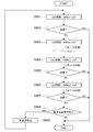
- It is a flowchart which shows a treatment protocol. It is a table showing the test results of the minimum erythema dose test.
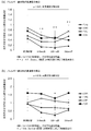
- (A) And (b) is a graph which shows the test result of the allergic reaction suppression test. It is a table which shows the test result of an allergic reaction suppression test.
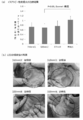
- (A) is a figure explaining the therapeutic effect with respect to allergic dermatitis of the light whose peak wavelength is in the range of 305 nm-335 nm
- (b) is a figure explaining the change of the affected part in the treatment of allergic dermatitis. is there.
- (A) is a figure explaining the irradiation conditions in the treatment of cutaneous lymphoma
- (b) is a figure explaining the change of the affected part in the treatment of cutaneous lymphoma.
- the present invention is based on the new finding that light having a peak wavelength in the range of 315 nm to 335 nm is effective for treating diseases in animals other than humans (especially dogs), as described later.
- the wavelength range of 315 nm to 335 nm is longer than the wavelength range (260 nm) that is likely to damage DNA (deoxyribonucleic acid), compared to the wavelength range (310 nm to 315 nm) that is considered to be effective (especially in humans). is there. Therefore, according to the present invention, it is possible to safely treat an animal for both the animal and a veterinarian who performs the treatment.
- the veterinary therapeutic device of the present invention is characterized by including at least one light emitting unit capable of outputting light having a peak wavelength in the range of 315 nm to 335 nm.
- the light emitting unit can output one or more kinds of light having a peak wavelength in the range of 315 nm to 335 nm.
- the light emitting unit includes at least one light source capable of outputting light in the range of 315 nm to 335 nm.
- the light source may be supported by a support.
- the light source is not particularly limited as long as it can output light in the range of 315 nm to 335 nm. Examples of the light source include a light emitting diode (LED), a laser diode (LD), a halogen lamp, a mercury lamp, and the like, and an LED or LD is particularly preferable.
- the light emitting section may comprise more than one light source, for example an array, matrix or cluster of light sources.
- the light emitting section may also include one or a plurality of light source modules configured of two or three types of light sources.
- the plurality of light sources or light source modules forming the light emitting unit may be independently controlled to be turned on and off. By independently controlling the turning on and off of the plurality of light sources or the light source module, it is possible to reduce unnecessary irradiation to the non-irradiated part (normal part other than the affected part).
- the light emitting unit may be configured to be able to output light having a peak wavelength in the range of 315 nm to 335 nm because the light source can output light having a peak wavelength in the range of 315 nm to 335 nm. Therefore, in an embodiment, the light emitting unit may include a light source capable of outputting light having a peak wavelength in the range of 315 nm to 335 nm. Alternatively, the light emitting unit outputs the light extracted from the light output from the light source using the suppressing member that suppresses the transmission of the light having the wavelength of less than 315 nm and the light having the wavelength of more than 335 nm in the peak wavelength range of 315 nm to 335 nm. May be output as light.
- the light emitting unit includes a light source capable of outputting light in the range of 315 nm to 335 nm and a suppressing member that suppresses transmission of light having a wavelength of less than 315 nm and / or light having a wavelength of more than 335 nm. You may have it.
- the suppression member is provided on the path of the light output from the light source.
- a specific example of the suppressing member is an optical filter (for example, a cut filter).
- the light emitting portion has a relative emission intensity of light having a wavelength of less than 315 nm in the output light, for example, 50% or less, preferably 40% or less, preferably 30% or less, more preferably 20% or less, more preferably 10% or less, It is more preferably 5% or less.
- a desired ratio for example, the above-mentioned value
- the light emitting unit transmits light having a wavelength of less than 315 nm on the light path from the light source. You may have the suppression member to suppress.
- the suppressing member for reducing the relative emission intensity of light having a wavelength of less than 315 nm may also serve as a suppressing member for extracting light having a peak wavelength in the range of 315 nm to 335 nm from the light output from the light source.
- the light emitting unit may be capable of outputting two or more types of light having a peak wavelength in the range of 315 nm to 335 nm, and may be configured to output one type of light selected from the two or more types of light.
- the switching means for switching to the selected light may be provided inside the light emitting unit or outside the light emitting unit (for example, inside the control unit described later).
- the two or more kinds of light having a peak wavelength in the range of 315 nm to 335 nm are lights having a peak wavelength in each of a plurality of continuous sections within the wavelength range of 315 nm to 335 nm.
- the one or more kinds of light having a peak wavelength in the range of 315 nm to 335 nm may be, for example, light having a peak wavelength in the range of 315 nm to 325 nm, or have a peak wavelength in the range of 325 nm to 335 nm. It may be light, and may be light having a peak wavelength in the range of 315 nm to 325 nm and light having a peak wavelength in the range of 325 nm to 335 nm.
- light having a peak wavelength in the range of 315 nm to 325 nm may be light having a peak wavelength in the vicinity of 320 nm (for example, within 320 nm ⁇ 3 nm or within 320 nm ⁇ 1 nm), and has a peak wavelength in the range of 325 nm to 335 nm.
- the light can be light with a peak wavelength near 330 nm (eg, within 330 nm ⁇ 3 nm or within 330 nm ⁇ 1 nm).
- the light emitting unit is capable of emitting light having a peak wavelength in the range of 305 nm to 315 nm in addition to one or more kinds of light having a peak wavelength in the range of 315 nm to 335 nm, and is selected from the above-mentioned lights. It may be configured to output one type of light. For example, light with a peak wavelength in the range of 305 nm to 315 nm can be light with a peak wavelength near 310 nm (eg, within 310 nm ⁇ 3 nm or within 310 nm ⁇ 1 nm).
- the switching means for switching to the selected light may be provided inside the light emitting unit or outside the light emitting unit (for example, inside the control unit).
- the light emitting unit may be capable of simultaneously outputting one or more kinds of light having a peak wavelength in the range of 315 nm to 335 nm and light having a peak wavelength in the range of 305 nm to 315 nm.
- the light emitting unit may be provided with a light source corresponding to each light that can be output, or a configuration capable of outputting two or more kinds of light by a combination of the light source and the suppressing material. May be said.
- the light emitting unit includes light sources of a number smaller than the types of light that can be output, and at least one suppressing material.
- the animal treatment device of the present invention may include two or more light emitting units.
- the plurality of light emitting units may be independently controlled to be turned on and off. By independently controlling the lighting and extinguishing of the plurality of light emitting units, it is possible to reduce unnecessary irradiation to the non-irradiated part (normal part other than the affected part).
- the light emitting unit may be combined with any optical component such as a lens, a reflecting mirror, a mask, a light guide and / or a diffusing plate.
- the light emitting unit may be provided with a transparent protective member on the light emitting surface when it can directly contact the animal.
- the animal therapeutic device of the present invention may further include a drive unit that drives the light emitting unit.
- the driving unit may include a driving circuit that drives the light emitting unit.
- the drive unit is electrically connected to the light emitting unit, and directly or indirectly supplies electric power to the light emitting unit.
- the drive unit can cause the light emitting unit to emit light under given light emitting conditions.
- the driving unit may cause only the light source to emit light to emit light under given light emitting conditions.
- the light emission conditions include the wavelength of the light output from the light emitting unit, the illuminance, the lighting time, the lighting mode (continuous or intermittent), the pulse width, the duty ratio, and the like.
- the light emission condition is input to the drive unit by, for example, a control signal directly received from a control unit described later, or a control signal from a storage unit (for example, a memory) in which the light emission condition is stored in advance. Therefore, in an embodiment, the drive unit comprises a storage means.
- the electric power may be supplied to the drive unit from the control unit or the battery.
- the battery may be chargeable / dischargeable, and in this case, the battery may be charged by electric power supplied from the control unit. Therefore, an embodiment of the veterinary treatment device of the present invention may accommodate a drive unit that drives the light emitting unit and a battery (preferably a chargeable / dischargeable battery) for supplying electric power to the drive unit. It may further include a battery accommodating portion. A battery properly housed in the battery housing may supply power to the drive. The power supply to the drive unit may be performed via the control unit described later.
- the driving unit is generally arranged in the vicinity of the light emitting unit or in the vicinity of the light emitting unit, but can be arranged remotely from the light emitting unit.
- the drive unit may be arranged in the same housing together with the light emitting unit, or may be arranged in a housing that does not include the light emitting unit.
- the drive unit may include a changeover switch operated by a user to switch between turning on and off the light emitting unit.
- the animal treatment device of the present invention may further include a control unit that controls the drive unit.
- the control unit may be configured to include a control circuit.
- the control circuit generates a control signal according to the irradiation condition of the light emitting unit and outputs the control signal to the driving unit.
- the control circuit may include a pulse width modulation circuit and / or a timer.
- the control unit may also include a storage unit (for example, a memory) that stores the irradiation condition.
- the control unit may be electrically connected to the driving unit. More specifically, the control unit may be electrically connected to the drive unit at all times, or may be electrically connected to the drive unit via a pair of adapters as necessary.
- the control unit may send a control signal regarding a light emitting condition of the light emitting unit to the driving unit.
- the controller may also supply power to the driver or (if applicable) a rechargeable battery.
- the control unit may include an interface for receiving an input regarding the light emitting condition of the light emitting unit.
- the interface may be a user interface (UI) that receives an input from a user or a communication interface.
- the light emission conditions input via the interface may be stored in the storage device.
- the UI may be in the form of, for example, a liquid crystal touch panel, or may be in the form of various switches (eg, rotary switch and / or push button switch).
- the interface need not be in close proximity to the control circuitry, but may be located remotely from the control circuitry.
- the UI is preferably provided at a position where the user can access the treatment device of the present invention most easily.
- the communication interface may be, for example, a wireless interface such as infrared communication, Bluetooth (registered trademark) or a short-range communication interface.
- the control unit determines which light source or light emitting unit should emit light. May be specified.
- the control unit may be arranged in the same housing together with the driving unit, or may be arranged in a housing that does not include the light emitting unit and the driving unit. In the latter case, the degree of freedom regarding the arrangement of the light emitting unit or the light emitting unit and the driving unit is increased, so that the treatment device of the present invention can be configured in various forms.
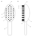
- the treatment device of the present invention can be provided in the form of, for example, a grooming device for animals (for example, a comb, a brush, gloves, etc.), a medical / sanitary device (for example, a toothbrush, a mouthpiece), a toy, clothes and the like. ..
- the control unit may further include a power supply or a battery holding unit as necessary.
- the power source may be, for example, an AC / DC adapter or a battery (preferably a chargeable / dischargeable battery).
- the control unit outputs when the light emitting unit can simultaneously output one or more kinds of light having a peak wavelength in the range of 315 nm to 335 nm and light having a peak wavelength in the range of 305 nm to 315 nm.
- the emission intensity of each light may be controlled so that the relative emission intensity of the light having a wavelength of less than 315 nm is, for example, 50% or less.
- the animal therapeutic device of the present invention may include a visible light source provided so as to be able to irradiate a region substantially the same as a light irradiation region having a peak wavelength in the range of 315 nm to 335 nm.
- a visible light source provided so as to be able to irradiate a region substantially the same as a light irradiation region having a peak wavelength in the range of 315 nm to 335 nm.
- the visible light source those known in the art (for example, a blue light source, a green light source, a red light source or a white light source) can be used.
- the visible light source may be disposed in the light emitting section or may be provided separately from the light emitting section. Visible light may be output simultaneously with light having a peak wavelength in the range of 315 nm to 335 nm, or may be output separately. When simultaneous output is possible, it is possible to easily recognize that light having a peak wavelength in the range of 315 nm to 335 nm is being output, and therefore safety is improved.
- the animal treatment device of the present invention may include a holding mechanism for holding the animal or a restraining mechanism for restraining the animal.
- the holding mechanism or the restraining mechanism is not particularly limited as long as it limits the free movement of the animal and allows the animal to stay within a predetermined area.
- the retention or restraint mechanism may be of the belt, harness or hammock type or enclosure, for example. Since the animal therapeutic device of the present invention comes into direct contact with at least a part of the animal or by the hand that comes into contact with the animal, the contact part is disinfected with, for example, sodium hypochlorite or disinfectant ethanol after each use. Preferably. Therefore, from the viewpoint of hygiene, at least a portion of the medical treatment device for animals of the present invention that can come into contact with an animal can be formed of a chemically resistant material.
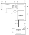
- FIG. 1 is a schematic configuration diagram of the animal phototherapy device 1.
- FIG. 2 is a block diagram of the phototherapy device 1 for animals.
- the animal phototherapy device 1 to which the present embodiment is applied includes a therapy device main body 10, a controller 30, and a cable 50.
- a therapy device main body 10 a controller 30, and a cable 50.
- each of the treatment device main body 10, the controller 30, and the cable 50 will be described.
- the treatment device body 10 outputs light having a wavelength in a predetermined range.
- the animal is treated by irradiating the animal (patient) with light from the treatment device body 10.
- the illustrated treatment device main body 10 includes a housing 11, a handle 13, an irradiation window 15, a changeover switch 17, and a pressing surface 19.
- the housing 11 accommodates functional constituent members such as a Light Emitting Diode 21 (LED 21, which will be described later) that is a light source inside.
- the housing 11 has an opening 14 through which the light from the LED 21 passes.
- the handle 13 is a part of the housing 11 and is a part that a user such as a veterinarian holds. The user turns the treatment device main body 10 toward the animal while gripping the handle 13, and irradiates the animal with light.
- the treatment device main body 10 can be changed to an arbitrary orientation depending on the position of the affected part in the body of the animal.
- the irradiation window 15 is a cover member that covers the opening 14 provided in the housing 11.
- the irradiation window 15 is composed of a cover glass or the like that can transmit light from the LED 21 provided inside the housing 11.
- the opening 14 and the irradiation window 15 in the illustrated example have a substantially rectangular shape in plan view, but the shapes thereof are not particularly limited.
- the illustrated irradiation window 15 is supported by a frame body 18 provided on the outer surface of the irradiation window 15.
- the changeover switch 17 is provided so as to project on the outer surface of the housing 11. The changeover switch 17, when pressed by the user, switches on and off of the LED 21.
- the pressing surface 19 is a part of the outer surface of the housing 11, and is a portion that is pressed against the affected part of the animal or around the affected part.
- the pressing surface 19 in the illustrated example is formed on the outer periphery of the opening 14.
- the housing 11 has an LED 21, an LED board 23, a cooling mechanism 25, a reflector 27, and an LED drive board 29 inside the housing 11.
- the LED 21 is composed of an LED group having different wavelengths.
- the LED 21 in the illustrated example includes a first LED 211, a second LED 212, and a third LED 213. Although details will be described later, the first LED 211 to the third LED 213 irradiate light having peak wavelengths of 310 nm, 320 nm, and 330 nm, respectively.
- the LED board 23 is a board on which the LED 21 is mounted.
- the LED board 23 supplies electric power to the LEDs 21 mounted on the board surface.
- the cooling mechanism 25 is provided on the LED substrate 23, and suppresses a temperature rise caused by the LED 21 emitting light.
- the cooling mechanism 25 is composed of a heat sink, an air cooling fan, and the like.
- the reflector 27 reflects the light from the LED 21 and focuses the light from the LED 21 on the irradiation field, that is, the affected part of the animal.
- the illustrated reflector 27 is formed in a mortar shape with the LED 21 provided on the bottom surface, and has an inner peripheral side surface 271 that is inclined in a direction in which the inner dimension increases as it goes to the irradiation window 15 side.
- the LED drive board 29 is a board electrically connected to the controller 30, the changeover switch 17, and the LED board 23.
- the LED drive board 29 receives a control signal and electric power from the controller 30 and the changeover switch 17, and supplies electric power to the LED 21 via the LED board 23. More specifically, the LED drive substrate 29 lights the LED 21 under the irradiation condition (described later) set by the controller 30 when the changeover switch 17 is on. Further, the LED drive board 29 forcibly stops the irradiation of the LED 21 when the changeover switch 17 is off. Further, the LED drive board 29 switches the LED to be turned on among the first LED 211 to the third LED 213.
- the LED drive board 29 may be electrically connected to the LED board 23 via a momentary switch (not shown).
- the momentary switch is movable between the open position and the closed position in association with the pressing surface 19 (or the pressing member 300 with a nozzle described later), and the pressing surface 19 (or the pressing member 300 with a nozzle).
- the LED 21 is turned on only while the pressing surface 19 (or the pressing member with nozzle 300) is pressed against the animal. Therefore, according to this configuration, the pushing surface 19 (or the pushing member 300 with a nozzle) is separated from the animal due to an unexpected movement of the animal, and the opening 14 (or the nozzle 305) faces toward an area other than the affected part of the animal. There is no risk of irradiation of a site other than the affected part of the animal or a veterinarian who operates this treatment device or its assistant, and the safety of treatment is further enhanced.
- the controller 30 supplies electric power to the treatment device body 10. Further, the controller 30 can set the irradiation condition of the light output from the LED 21. More specifically, the controller 30 can set the irradiation conditions such as illuminance, irradiation time, lighting mode (continuous lighting or pulse lighting), wavelength, pulse width, duty ratio, and the like.
- the illustrated controller 30 has a user interface (UI) 31, a control board 33, and a power supply 35.
- the UI 31 is composed of a liquid crystal panel or the like. When operated by the user, the UI 31 receives an input relating to irradiation conditions such as the wavelength of light output from the LED 21.
- the control board 33 is connected to the UI 31 and the power supply 35, and is also connected to the LED drive board 29 of the treatment device body 10 via the cable 50.
- the control board 33 supplies a control signal according to the irradiation condition received by the UI 31 and the power from the power supply 35 to the LED drive board 29.
- the power supply 35 supplies electric power to the control board 33 and the like.
- the power supply 35 may be directly connected to a household power supply (for example, 100 volts in countries such as Japan, 120 volts in countries such as the United States, 220 volts in countries such as China).
- the cable 50 is a signal line that sends control signals and electric power between the treatment device body 10 and the controller 30. In the illustrated configuration, power is supplied through the cable 50 even when the treatment device main body 10 is outputting light, and the treatment device main body 10 is allowed to continue outputting light for a long time. Is possible.
- FIG. 3 is a diagram showing an emission spectrum of the LED 21.
- the LED 21 has the first LED 211 to the third LED 213.
- the first LED 211 to the third LED 213 are common in that they output ultraviolet light.
- the peak wavelengths of the lights of the first LED 211 to the third LED 213 are different from each other. Specifically, as shown in FIG. 3, the peak wavelengths of the lights of the first LED 211 to the third LED 213 are about 310 nm, about 320 nm, and about 330 nm.
- the peak wavelength of the first LED 211 is in the range of 305 nm to 315 nm.
- the peak wavelength of the second LED 212 is within the range of 315 nm to 325 nm.
- the peak wavelength of the third LED 213 is in the range of 325 nm to 335 nm. That is, the first LED 211 to the third LED 213 are configured such that the peak wavelength range in each of them is different from each other.
- the peak wavelength of the light output from the LED 21 changes depending on which of the first LED 211 to the third LED 213 is turned on. Specifically, when any one of the first LED 211 to the third LED 213 is turned on, light having a peak wavelength of 310 nm, 320 nm, or 330 nm is output from the treatment device body 10. In addition, when two or three of the first LED 211 to the third LED 213 are turned on, light having a peak wavelength of two or three is output from the treatment device body 10. When the second LED 212 and / or the third LED 213 is turned on, light having a peak wavelength in the range of 315 nm to 335 nm is output from the treatment device body 10.
- the pulse width and the duty ratio can be set as described above as the irradiation conditions for irradiating the first LED 211 to the third LED 213.
- any of the first LED 211 to the third LED 213 may be pulse-emitted with a pulse width of 10 ms or less and a duty ratio of 10% or less.
- the light output from each of the first LED 211 to the third LED 213 may be simply referred to as “310 nm light”, “320 nm light”, and “330 nm light”.
- FIGS. 4A and 4B are views for explaining a modified example of the animal phototherapy device 1.
- a modified example of the animal phototherapy device 1 will be described with reference to FIGS. 4 (a) and 4 (b).
- the so-called handy type configuration in which the user holds the treatment device main body 10 has been described, but the present invention is not limited to this.
- an animal phototherapy device 100 as shown in FIG. 4 (a) may be used.
- the animal phototherapy device 100 includes a first irradiation device 111, a second irradiation device 113, and a restraint mechanism 130.
- the 1st irradiator 111 and the 2nd irradiator 113 have the 1st LED121 and the 2nd LED123, respectively.
- the first irradiator 111 and the second irradiator 113 are installed on the floor surface 190 without being gripped by the user. More specifically, the first irradiator 111 and the second irradiator 113 are arranged on the floor surface 190 with the surfaces provided with the first LED 121 and the second LED 123 facing each other.
- the animal An is arranged in the space sandwiched by the first irradiator 111 and the second irradiator 113.
- the animal An is in a state in which its movement is restricted by being restricted by a restriction mechanism 130 fixed to, for example, the ceiling.
- the first LED 121 and the second LED 123 are provided in a plane shape in each of the first irradiator 111 and the second irradiator 113. Moreover, the 1st LED121 and the 2nd LED123 can output the light of 310 nm, the light of 320 nm, and the light of 330 nm. With this configuration, it is possible to irradiate a wide range of the body of the animal An, such as the whole body of the animal An, with light having a predetermined wavelength.
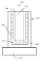
- an animal phototherapy device 200 containing an animal An may be used.
- the animal phototherapy device 200 includes a container 210, first LEDs 221 to sixth LEDs 226, and a restraint mechanism 230.
- the container 210 has a space for accommodating the animal An inside, and the animal An can be arranged inside via a door (not shown). Further, the first LED 221 to the sixth LED 226 are provided on the inner surface of the container 210.
- the container 210 may be an intensive care BOX.
- the first LED 221 is provided on the floor surface 215 inside the housing 210
- the second LED 222 and the third LED 223 are provided on side surfaces 216 inside the housing 210
- the fourth LED 224 to the sixth LED 226 are top surfaces inside the housing 210. 217.
- the first LED 121 to the sixth LED 126 are provided in a planar shape on each surface (floor surface 215, side surface 216, top surface 217) inside the housing 210.
- or 6th LED126 can output the light of 310 nm, the light of 320 nm, and the light of 330 nm. With this configuration, it is possible to irradiate a wide range of the body of the animal An, such as the whole body of the animal An, with light having a predetermined wavelength.
- the animal light therapy device 100 shown in FIG. 4 (a) can be regarded as an open-type therapy device because the animal An is placed in an open space for treatment.
- the animal phototherapy device 200 shown in FIG. 4B can be regarded as a closed-type therapy device because the animal An is placed in a closed space for treatment.
- the animal An in order to suppress the irradiation of the eyes of the animal An with ultraviolet rays, the animal An may be equipped with protective glasses for cutting the ultraviolet rays.
- the goggles may be goggles.
- a protective member such as a seal may be attached instead of the protective glasses.
- the animal phototherapy device 100 shown in FIG. 4A has the harness type restraining mechanism 130
- the animal phototherapy device 200 shown in FIG. 4B is the hammock type restraining mechanism 230.
- the configuration is not limited to the configurations of the restraint mechanisms 130 and 230 shown in the figure as long as the movement of the animal An is limited during the treatment.
- the movement of the animal An may be restricted by a gauge (enclosure) or the like.
- the user can perform treatment without pressing the body of the animal An. Therefore, the influence on the user of the animal light therapy device 100, 200 or the like can be suppressed, and the treatment becomes easy.
- the animal light therapy device 100 or 200 may include a distance measuring device that measures the distance from each LED to the animal An.
- the control unit estimates the irradiation amount from the LED to the animal based on the measured distance, and increases or decreases the illuminance of the LED as necessary. For example, the control unit increases the illuminance of the LED when the distance from the LED to the animal becomes larger than a predetermined value (that is, when the irradiation amount from the LED becomes lower than the predetermined value), and conversely becomes smaller than the predetermined value. Then (that is, when the irradiation amount from the LED increases above a predetermined value), the illuminance of the LED is decreased.
- the irradiation amount may be confirmed by using an integrated light amount measured by an ultraviolet light amount distribution measuring film attached to an animal (for example, UV scale manufactured by FUJIFILM).
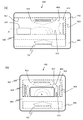
- FIGS. 5A to 5C are views for explaining a modified example of the animal phototherapy device 1.
- a modified example of the animal phototherapy device 1 will be described with reference to FIGS. 5 (a) to 5 (c).
- the user irradiates light while pressing the pressing surface 19 of the treatment device body 10 to the affected part or the periphery of the affected part of the animal, but without contacting the treatment device body 10 with the animal, It may be irradiated with light. That is, the affected area may be irradiated with light at a position where the pressing surface 19 of the treatment device body 10 is separated from the affected area of the animal.
- the pressing surface 19 of the treatment device body 10 is irradiated with light in a contact state.
- the user is illuminated with light.
- the pressing member 300 with a nozzle as shown in FIGS. 5A to 5C may be detachable from the treatment device body 10.
- the nozzle pressing member 300 is attached to the opening 14 of the treatment device body 10 to narrow down the passage area of the light emitted from the treatment device body 10.
- the illustrated nozzle pressing member 300 has a cover portion 301, a through hole 303, and a nozzle 305.
- the cover portion 301 is a member that covers the opening 14 and the pressing surface 19.
- the cover portion 301 in the illustrated example has a base portion 306 that is a flat plate member having a substantially rectangular shape in plan view, and an edge portion 307 that rises from the outer periphery of the base portion 306.
- a through hole 303 is formed in the center of the plate surface of the base 306. Then, the tip of the treatment device body 10 is inserted into the space formed by the base portion 306 and the edge portion 307, so that the cover portion 301 is positioned with respect to the treatment device body 10. Further, in the positioned covering portion 301, the through hole 303 is arranged at a position facing the opening 14.
- the nozzle 305 is a substantially cylindrical member that rises from the outer periphery of the through hole 303. Further, a reflective layer 309 formed of, for example, an aluminum film is provided on the inner peripheral surface of the nozzle 305.
- the pressing member with nozzle 300 configured as described above When the pressing member with nozzle 300 configured as described above is attached to the treatment device body 10, light is emitted through the through hole 303 and the nozzle 305. In other words, the light from the LED 21 is emitted only from the tip of the nozzle 305.
- the LED 21 By letting the LED 21 emit light with the tip of the nozzle 305 inserted in the ear of an animal or the like, it is possible to suppress light from leaking to a portion other than the affected area. As a result, the irradiation of the leaked light to the user is reduced.
- the pressing member with nozzle 300 may be formed according to the shape of the affected area.
- the outer diameter of the nozzle 305 may be changed for each affected area. Specifically, when the affected area is an ear hole, the outer diameter of the nozzle 305 may be 20 mm, and when the affected area is a nostril hole, the outer diameter of the nozzle 305 may be 7 mm, which is a smaller diameter.
- the reflection layer 309 on the inner peripheral surface of the nozzle 305, a large amount of light can be irradiated to the affected area.
- a bowl-shaped or truncated cone-shaped pressing member may be attached to the treatment device body 10 instead of the pressing member 300 with a nozzle.
- the bowl-shaped or truncated cone-shaped pressing member is attached to the opening 14 of the treatment device body 10 to prevent light emitted from the treatment device body 10 from leaking to the outside.
- the bowl-shaped or frustoconical pressing member has a fitting portion that can be fitted to the tip of the treatment device body or a receiving portion that can receive the tip, and a bowl-shaped or frustoconical reflector portion.
- a reflective layer formed of, for example, an aluminum film is provided on the inner side surface of the reflector portion.
- the opening of the reflector portion may be formed in a size and shape corresponding to the shape of the irradiated portion in the animal to be treated, or may be deformable in accordance with the shape of the irradiated portion. ..
- the opening of the reflector portion may be made to order (for example, using a 3D printer) for an individual to be treated, or an elastic member such as a sponge or a member such as a molding cage may be attached. Therefore, it may be possible to make close contact with the periphery of the irradiated portion.
- the animal phototherapy device 1 may be configured without the cable 50. That is, the treatment device body 10 and the controller 30 may not be physically connected.
- an adapter is formed in each of the treatment device body 10 and the controller 30. Then, one adapter can be attached to and detached from the other adapter.
- the treatment device main body 10 has a storage unit that stores the irradiation condition set by the controller 30. As a result, even when the treatment device body 10 is separated from the controller 30, the treatment device body 10 can operate according to the irradiation conditions stored in the storage means.
- the treatment device 1 of the present invention may be provided with a mechanism that emits a sound or a smell when the LED is turned on. Sounds or odors can have the effect of calming and calming the animal and thus suppressing the stress of the animal. In addition, the user can recognize the lighting of the LED.
- the sound or odor emitting mechanism is preferably capable of selecting multiple music or odors so that the animal does not get tired.
- the sound can be music (eg, classical), the owner's voice, the sound of waves, the sound of a candy bag (a rustling sound), and the like.
- the light of the animal phototherapy device 100 is applied to the skin of the dog, but the invention is not limited to this.
- animals other than dogs may be irradiated with light.
- the animal phototherapy device 1 may be used for the treatment of mammals (cats, horses, cows, pigs, rabbits, etc.), birds (chickens, etc.), reptiles (lizards, etc.), and it is not limited to humans. There is no particular limitation on the animals to be treated.
- the animal's body may be irradiated not only on the skin of the animal but also on the mucous membranes of the animal's ears or inside the mouth, and further incising a part of the animal's body. Irradiation may be applied to the exposed portion, and the irradiation method for the animal body is not particularly limited.
- the animal phototherapy device 1 or the like outputs light of 310 nm, 320 nm, 330 nm, but is not limited thereto. ..
- the peak wavelength may be in the range of UV-B (280 nm to 315 nm) and UV-A (315 nm to 400 nm). More preferably, the peak wavelength should be in the range of 280 nm to 340 nm.
- the relative emission intensity of light below 315 nm may be 30% or less.
- the relative emission intensity of light of less than 315 nm is low. Therefore, it is preferable that the relative emission intensity of light having a peak wavelength of 315 to 335 nm is 15% or less, and the relative emission intensity of light of less than 315 nm is 5 or less. % Or less, and more preferably the relative emission intensity of light of less than 315 nm is 0%.
- the light with a relative emission intensity of light of less than 315 nm of 30% or less is obtained by emitting light from an LED that outputs light with a peak wavelength of 315 nm and an LED that outputs light with a peak wavelength of 326 nm. You can Note that these LEDs have the same irradiance.
- the light having a relative emission intensity of light of less than 315 nm of 15% or less is obtained by causing an LED that outputs light having a peak wavelength of 320 nm and an LED that outputs light having a peak wavelength of 326 nm to emit light. be able to.
- the light having a relative emission intensity of 5% or less of the light having a wavelength of less than 315 nm can be obtained by, for example, causing an LED that outputs light having a peak wavelength of 326 nm to emit light. Further, the light having a relative emission intensity of 0% of the light of less than 315 nm causes, for example, an LED that outputs light having a peak wavelength of 315 nm and an LED that outputs light having a peak wavelength of 335 nm to emit light, and the wavelength of 315 nm. It can be obtained by transmitting a cut filter that absorbs or reflects less light.
- the irradiation window 15 provided in the path of the light from the LED may be a cut filter.
- one or a plurality of peak wavelengths may be present at 315 to 325 nm, and the relative emission intensity of light below 315 nm may be 50% or less. Further, it has one or a plurality of peak wavelengths in 315 to 325 nm, and the relative emission intensity of light of less than 315 nm is preferably 20% or less, more preferably the relative emission intensity of light of less than 315 nm is 5% or less. And more preferably the relative emission intensity of light of less than 315 nm is 0%.
- the light with a relative emission intensity of light of less than 315 nm of 50% or less can be obtained by, for example, causing an LED that outputs light of a peak wavelength of 315 nm to emit light.
- the light having a relative emission intensity of light of less than 315 nm of 20% or less can be obtained by causing an LED that outputs light having a peak wavelength of 320 nm to emit light.
- the light having a relative emission intensity of 5% or less of the light having a wavelength of less than 315 nm can be obtained by causing an LED that outputs light having a peak wavelength of 325 nm to emit light.
- the light having a relative emission intensity of 0% of the light of less than 315 nm causes, for example, an LED that outputs light having a peak wavelength of 320 nm to emit light and transmits a cut filter that absorbs or reflects light of a wavelength of less than 315 nm. It can be obtained.
- the wavelength of the light to be applied may be selected according to the thickness of the skin in the irradiation field.
- short wavelength light of 310 nm
- long wavelength light of 310 nm
- Light of 320 nm When irradiating even thinner skin such as the axilla, the wavelength may be longer (330 nm light).
- 320 nm light, 310 nm light, or the like can be appropriately selected in response to phototherapy. Further, it is possible to simultaneously irradiate light of 310 nm and light of 320 nm or 330 nm with a combination of emission intensities such that the relative emission intensity of light having a wavelength of less than 315 nm is, for example, 50% or less. At this time, the 310 nm light is preferably less than the minimum erythema dose.
- 310 nm light has an irradiation dose of 300 mJ / cm 2 or less, 200 mJ / cm 2 or less, 100 mJ / cm 2 or less, 50 mJ / cm 2 or less, and 320 nm or 330 nm light has 400 mJ / cm 2 or more, 600 mJ / cm 2 or more.
- the combination may have a dose of 2 or more, 1000 mJ / cm 2 or more, and 1500 mJ / cm 2 or more.
- an arbitrary visible light (360 nm to 830 nm) is irradiated simultaneously with the light having a peak wavelength in the range of 315 nm to 335 nm. It is also possible to improve the visibility of light. Visible light may be blue, green, or red that is easily visible to humans. With this mechanism, it is possible to prevent forgetting to turn off the light source of the phototherapy device and ensure the safety of the veterinarian.
- an image for selecting whether the irradiation field is thick skin or thin skin is displayed on the UI 31 of the controller 30, and the wavelength of the output light is determined by operating the image. Good. Further, for example, on the UI 31 of the controller 30, an image for selecting a part of the irradiation field (nose, back, etc.) or the degree of thickening of the skin is displayed, and the wavelength of the output light is changed as the image is operated. May be determined.
- the LED 21 or the like is used as the light source, but the light source is not particularly limited.
- a light source other than the LED such as a UV lamp may be used.
- the LED 21 or the like as the light source, it becomes easy to control the illuminance.
- the animal phototherapy device 1 may have a configuration in which the wavelength of light cannot be switched, that is, a configuration in which light of a single wavelength is output.
- the animal phototherapy device 1 is an example of an animal therapy device and a phototherapy device.
- the LED substrate 23 is an example of a support.
- the cut filter is an example of a suppressing member.
- the second LED 212 is an example of a light source.
- the third LED 213 is an example of another light source.
- the first LED 211 is an example of yet another light source.
- the LED drive board 29 is an example of a switching unit.
- the control board 33 is an example of a control unit.
- the light of 310 nm is an example of the first light.
- the light of 320 nm is an example of the second light.
- the LED 21 is an example of a light emitting unit.
- the animal therapeutic device 400 includes a pedestal 440 on which an animal limb (particularly limb) Al is placed, and light-emitting units 421, 422, and 423 for irradiating an irradiation region provided on the pedestal upper surface 415 with ultraviolet light. 424, and a cover portion 442 that covers the base portion from above and that has an opening portion or a cutout portion 444 for allowing the limbs of the animal to pass therethrough.
- the irradiated part by keeping the affected part as the irradiated part at a predetermined position on the table part, it becomes possible to keep the distance between the affected part and the light emitting part constant, and as a result, the irradiated part It is possible to suppress variations in the illuminance of light with which the area is illuminated. Especially when the light emitting part is arranged below the platform part, regardless of the size of the animal, it is possible to suppress the variation in the illuminance of the light irradiating the affected part (for example, the back of the limb or the affected part between the pad and bulb). it can.
- the light emitting units 421 to 424 can irradiate from above and / or below and / or laterally and / or from behind (with respect to the opening or notch 444) of the pedestal toward an irradiation area provided on the pedestal upper surface 415.
- the irradiation is preferably performed from above and / or below the pedestal, and more preferably from below.
- the light emitting portion may be formed on the lower surface of the base portion and / or on the top surface forming portion 417 of the cover portion 442 and / or on one or two or three side surface forming portions 416.
- the base unit 440 When the light emitting unit 421 is disposed below the base unit 440, at least a portion corresponding to the irradiation region of the base unit is formed of a material having a light transmitting property with respect to the light output from the light emitting unit. Examples of such a material include UV transparent glass such as quartz glass, UV transparent resin such as acrylic resin or silicone resin, and fluorine resin.
- the base portion may function as a protective member for the light emitting surface of the light emitting portion.
- the platform 440 may be provided with a guide (for example, one composed of a concave portion or a convex portion) that guides the limbs (particularly the limbs) of the animal to an appropriate position with respect to the irradiation region.
- the guide can be, for example, a concave portion or a convex portion that defines the irradiation area.
- the lower part of the table part if present, may be covered with the lower cover part 446 together with the light emitting part 4
- the driving unit is preferably arranged in the vicinity of the light emitting unit or in the vicinity of the light emitting unit, but can be appropriately arranged in any place of the present treatment device.
- the control unit may be appropriately arranged in any place in the treatment device.
- the UI can be provided, for example, on the outer surface above or on the side of the cover portion.
- the control unit is disposed in a control unit located outside the treatment device main body including the base portion 440, the light emitting portions 421 to 424, the cover portion 442, and the lower cover portion 446 if necessary, and the UI May be provided on the upper surface and / or the side surface of the control unit.
- the treatment device main body and the control unit are electrically connected by a cable.
- the size of the opening or notch 444 of the cover is not particularly limited as long as it can pass one or two limbs of the animal to be treated.
- the opening or notch may be, for example, substantially rectangular.
- the lower side thereof is preferably located on the same horizontal plane as or lower than the upper surface of the base.
- the treatment device may include a retaining mechanism 450 that retains the limb of the animal placed on the platform by pressing it against the platform upper surface 415.
- the retention mechanism 450 can be a belt.
- the belt may have hook and loop fasteners to secure the two ends.
- the base may have two slits for passing the belt, or the end of the belt may be fixed to the base.
- the belt may include, for example, an elastic member on the inner side (the side in contact with the limb of the animal).
- the retaining mechanism 450 is configured to include a pressing portion 452 that interlocks with the opening / closing operation of the lid body 446 that can be opened / closed provided on the cover portion.
- the pressing portion 452 When the lid body 446 is closed, the pressing portion 452 is pressed. Alternatively, when the 452 is pushed down to press the animal's limb against the upper surface of the base part and the lid 446 is opened, the pressing part 452 may be pulled up to open the limb of the animal.
- the pressing portion 452 may be an elastic body, more specifically, a sponge (for example, foam of rubber or synthetic resin).
- the animal's limb (irradiated portion) is positioned on the pedestal top surface 415 simply by closing the lid after placing the limb of the animal on the top surface of the pedestal with the lid pulled up. The positioning operation can be facilitated.
- the retaining mechanism may include an inflatable and inflatable airbag and a limiting member that limits the inflation of the airbag upward with respect to the platform.
- the airbag inflated by injecting air exerts a downward urging force as a result of the upward inflation being limited by the limiting member.
- the limiting member may be a belt-shaped body fixed to the base or a top surface of the cover.
- a specific example of the retaining mechanism is a cuff type.
- the treatment device may include a sensor 460 that detects whether or not the limb of the animal is located within the irradiation area on the upper surface of the platform.
- the sensor 460 is electrically connected to the control unit, and when detecting that the limb of the animal is located in the irradiation area, the control unit inputs the light emitting unit to a user or the like (for example, the light emitting unit described in the first embodiment).
- the switch can be turned on / off according to (switch switch for switching on / off), and when it is detected that the limb of the animal is not in the irradiation area, the light-emitting unit is input according to the user's input (for example, even when the switch is lit).
- the control unit may be configured to be in a state where it cannot be lit.
- the timer may be configured to stop when the light emitting unit is turned off and measure the time when the light emitting unit is turned on, that is, the time when the treatment light is actually applied to the affected area. Good.
- the irradiation time can be measured more accurately, so that the irradiation amount can be controlled more strictly.
- the treatment device of the present embodiment is effective for irradiating an affected part of an animal's limb, particularly a finger or a space between the fingers (between the follicle).
- the treatment device body is provided in the form of a glove, eg, a grooming glove.
- a glove eg, a grooming glove.
- FIG. 8 is a schematic configuration diagram of an embodiment of a veterinary treatment device.
- the schematic configuration of the veterinary treatment device of the present embodiment will be described with reference to FIG. 8.
- the treatment device main body 510 of this form includes a glove main body 502 into which a human hand can be inserted, at least one light emitting unit 521 arranged on the palm-side outside 504 of the glove main body, and a driving unit 523.
- the light emitting unit 521 may be arranged on the palm portion and / or the finger portion of the glove.
- the driving unit 523 may be arranged on the instep side outer side 506 of the glove body.
- the treatment device main body 510 may include a battery accommodating portion 525, for example, in the outside 506 of the glove main body. In this case, since electric power is supplied from the battery housed in the battery housing part, it is not necessary to connect the treatment device main body to an external power source during use.
- the control unit may or may not be arranged on the treatment device body (glove body). When the control unit is not disposed on the glove body, the driving unit 523 disposed on the glove body may be electrically connected to the control unit 530 outside the treatment device body via the pair of adapters 541 and 542.
- the glove body 502 may be provided with one of the pair of adapters 541 electrically connected to the drive unit 523 and the battery housing unit 525 as necessary, and the other adapter 542 is provided outside the glove body.
- the control unit 530 can be electrically connected by a cable 550.
- control unit 530 and the drive unit 523 are electrically connected via the pair of adapters 541 and 542, the control unit 530 transmits the data to the memory provided in the drive unit 523.
- Information regarding the light emission conditions of the light emitting unit 521 is stored, and in some cases, the battery housed in the battery housing unit 525 is charged with the electric power supplied from the control unit 530.
- a switch 527 may be provided on the outside 506 of the glove body on the instep side to turn on / off the light emitting unit 521 and switch the emission wavelength as necessary.
- Protrusions 560 for grooming or combing may be arranged on the palm side exterior 504 of the glove body.
- the protrusions 560 may be located on the palm and / or finger portions of the glove. In the case of having a protrusion, light can be emitted while turning over the body hair, so that light irradiation to the diseased part (particularly, the affected part having body hair, for example, the affected part at the initial stage of atopic dermatitis) can be efficiently realized.
- the material of the protrusions is not particularly limited as long as it can be used for grooming or combing, but may be, for example, a resin (for example, an acrylic resin or a silicone resin, a UV transparent resin such as a fluorine resin). .
- the shape and size of the protrusion can be appropriately determined depending on the target animal.
- the protrusion may be comb-shaped.
- the treatment device body is provided in the form of a brush or a comb. According to this form, since light irradiation can be performed while combing the hair, it is possible to reduce the stress of the animal being treated, in addition, to the affected area having body hair (for example, the affected area at the initial stage of atopic dermatitis). The light irradiation can be efficiently performed.
- FIG. 9 is a schematic configuration diagram of the veterinary therapeutic device 700. The schematic configuration of the veterinary therapeutic device 700 according to the present embodiment will be described with reference to FIG. 9.
- the veterinary treatment device 700 includes a plurality of brush pins 760, a support body 770 that supports the brush pins, and a plurality of light emitting units 721 provided on the support bodies.
- the light emitting unit 721 is provided on the support body 770 so that the light from the light emitting unit can be emitted from between the brush pins 760.
- the light emitting portions may be arranged between the rows.
- the brush pins may be arranged around the light emitting unit, for example.
- the light emitting unit 721 may be provided in a recess provided in the support body 770. In this case, the opening of the recess may be covered with a member that is transparent to the light output from the light emitting unit (also simply referred to as “transparent” in the present specification).
- the shape and size of the brush pin 760 can be appropriately determined according to the target animal.
- the brush pin 760 may be a light guide (for example, UV-transparent glass such as quartz glass or UV-transparent resin such as acrylic resin or silicone resin, fluororesin), that is, as a light guide path of light output from the light emitting unit.
- a light guide for example, UV-transparent glass such as quartz glass or UV-transparent resin such as acrylic resin or silicone resin, fluororesin
- the brush pin is a light guide, the light output from the light emitting unit can be irradiated over a wide range without being blocked by the brush pin, and as a result, the variation in the illuminance of the light irradiated to the irradiated portion can be suppressed. Will be easier.
- the veterinary treatment device 700 may further include a back cover portion 780 that covers the back surface (the surface where the brush pins are not provided) of the support body 770, and may further include a grip portion or a handle portion 790. .
- the back cover part may be integrated with the grip part or the handle part.
- the drive unit may be arranged as a set with each light emitting unit, or may be arranged collectively in an internal space defined by the support and the back cover unit. If necessary, the battery accommodating portion may be arranged in the internal space, or may be arranged in the internal space of the grip portion or the handle portion.
- the control unit may be arranged on the outer surface of the back cover unit, or a part (for example, a control circuit) may be arranged in the internal space and a part (for example, UI) may be arranged on the outer surface of the back cover unit.
- a part for example, a control circuit
- UI for example, UI
- the treatment device main body (for example, the outer surface of the back cover portion or the grip portion or the handle portion) may be provided with a changeover switch for turning on / off the light emitting portion and switching the emission wavelength as necessary.
- FIG. 10 is a schematic configuration diagram of the veterinary treatment device 900.
- the animal treatment device 900 includes a plurality of brush pins 960, a support 970 that supports the brush pins, and a plurality of light emitting units 921 provided on the side opposite to the brush pins with respect to the support.
- the light emitting portion 921 is provided so as to face the base portion of the brush pin 960 with the support body 970 interposed therebetween.
- the support 970 is transparent and the brush pin 960 is a light guide.
- the light output from the light emitting unit 921 passes through the support 970, is further conducted inside the brush pin 960, and is emitted to the brush pin side (as a result, the animal can be irradiated).
- a part of the light output from the light emitting unit 921 may pass through the support 970 and be emitted to the brush pin side.
- the light emitting unit is provided so as to face the plurality of openings (or irradiation windows) of the support, and the light output from the light emitting unit passes through the openings (or irradiation window) and is emitted to the brush pin side. May be done.
- FIG. 11 is a schematic configuration diagram of the veterinary therapeutic device 1000.
- the animal treatment device 1000 includes a plurality of brush pins 1060, a support 1070 that supports the brush pins and is a light guide, and one or a plurality of light emitting units 1021 arranged at one or more ends of the support. Equipped with.
- the light output from the light emitting unit enters the support (light guide) from its end and exits from the surface 1071 on which the brush pin is provided.
- a reflective surface may be provided on the surface 1972 of the support on which the brush pin is not provided.
- Brush pins can also be light guides.
- FIG. 12 is a schematic configuration diagram of the veterinary therapeutic device 1100 of the fifth embodiment.
- the schematic configuration of the veterinary therapeutic device 1100 will be described with reference to FIG.
- the veterinary treatment device 1100 includes a cylinder 1110 that surrounds or accommodates an affected part of an animal's limb, and a light emitting unit 1121 that is arranged to be capable of irradiating the lumen 1112 of the cylinder.
- the barrel 1110 may have a circular or polygonal inner shape and / or outer shape in a cross section perpendicular to the lumen axis (eg, square, pentagonal, hexagonal, octagonal).
- a barrel may be a cylinder.
- the tubular body may be configured so that two half-divided bodies are united into a tubular shape.
- the two halves are connected by a connecting mechanism (for example, a hinge) and are held in a united state by a locking mechanism (for example, a hook and loop fastener, a patch lock).
- the barrel may or may not have a bottom. When the barrel does not have a bottom, the animal equipped with the treatment device of the present embodiment is not restricted in movement, and thus stress during use can be reduced.
- the tubular body 1110 has its lumen axis arranged parallel to the vertical axis, but it may also be arranged inclined from the vertical axis.
- the cylinder 1110 may be supported by the base 1140.
- the light emitting unit 1121 is arranged so as to be able to irradiate at least a part of the internal cavity 1112 of the animal so that the affected part of the animal can be illuminated when the affected part is surrounded or accommodated in the internal cavity 1112 of the tubular body 1110. Good.
- the light emitting portion 1121 can be provided on the side surface 1114 of the tubular body cavity 1112. Further, as shown in FIG. 9, when the tubular body 1110 is a bottomed tubular body, it can be provided on the bottom surface 1116 of the inner cavity 1112 in addition to or instead of the side surface 1114.
- a plurality of light emitting units may be provided on the side surface 1114 so as to surround the lumen 1112.
- a plurality of (for example, 2 to 10, more specifically 2, 3, 4, 5, 6, 7 or 8) linear light emitting units may be provided in parallel to the lumen axis.
- a transparent protective member 1148 may be provided on the lumen side of the light emitting unit.
- the driving unit is preferably arranged in the vicinity of the light emitting unit 1121 or in the vicinity of the light emitting unit, but may be appropriately arranged in any place of the treatment device 1100.
- the control unit may be appropriately arranged at any place in the treatment device 1100.
- the UI can be provided on the outer surface of the cylinder 1110 or the upper surface of the base 1140, for example.
- the control unit is located outside the main body of the treatment device that is configured to include the cylindrical body 1110 that surrounds or houses the affected part of the limb of the animal and the light emitting unit 1121 that is arranged to be able to irradiate the inner cavity 1112 of the cylindrical body.
- the UI may be provided in the control unit and may be provided on the upper surface and / or the side surface of the control unit. In this case, transmission of the control signal and supply of electric power from the control unit to the treatment device body are performed by wire or wirelessly.
- the electric power supplied to the treatment device main body may be used to charge the battery accommodated in the battery storage part, when the treatment device main body includes the battery storage part.
- An inflatable airbag may be provided in the inner cavity of the cylindrical body.
- the airbag inflated by injecting air can hold the limb of the animal in a predetermined position within the lumen of the barrel. As a result, it is possible to keep the distance between the affected part and the light emitting part constant, and it is possible to suppress variations in the illuminance of the light with which the irradiated part is irradiated.
- the material of the airbag is preferably transparent. By being transparent, the irradiation of the light emitted from the light emitting unit to the irradiated portion is not blocked by the inflated airbag.
- the airbag may function as a protective member for the light emitting unit.
- the cylindrical body may be provided with a light-shielding cover for preventing light output from the light emitting unit from leaking to the outside from one or two openings of the cylindrical body.
- the light-shielding cover is, for example, a lid having a through hole in the center for passing an animal's limb.
- the tubular body is composed of two half-divided bodies, when the light-shielding cover is united, a through hole for passing the animal's limb is formed in the center, and the two light-shielding covers are attached to the two half-divided bodies. It may be composed of a half body.
- An inflatable airbag made of an opaque material may be provided in the vicinity of the opening of the cylindrical body cavity.
- the airbag can function as a retention mechanism and a light shielding mechanism for the animal limb.
- the treatment device of the present embodiment is effective for irradiating an affected part of an animal limb, and in particular, when the treatment device main body is a bottomed cylindrical body having a light emitting part on the inner bottom surface, a finger or It is effective in irradiating the affected area between the fingers (between the pads).
- the treatment device main body may be wearable.
- a treatment device body may be, for example, a clothing type, a belt type, or a boot type.
- the clothing type treatment device body may have a clothing part having a vest shape, a pants shape, a sweater shape, or the like.
- the belt type treatment device main body is attached to the animal by winding the belt portion around the body or limb of the animal.
- the belt portion may be provided with locking mechanisms at both ends.
- the locking mechanism is a hook-and-loop fastener, for example, the treatment device main body can be easily attached to the animal by sticking the hook-and-loop fasteners together.
- the boot type treatment device body may have a shape in which the boot portion can accommodate the tip of an animal's limb. It is preferable that the material of the clothing portion, the belt portion or the boot portion is impermeable to the ultraviolet light output from the light emitting portion.
- FIG. 13 is a schematic configuration diagram of a veterinary treatment device 1200 in a clothing form.
- the schematic configuration of the veterinary therapeutic device 1200 will be described with reference to FIG. 13.
- the veterinary treatment device 1200 includes a clothing main body 1210 and a light emitting unit 1221 arranged inside the clothing main body (on the side facing the animal when worn).
- the light emitting unit 1221 may be fixed to a specific position, or may be fixed by a detachable mechanism (for example, a surface fastener) so that the light emitting unit 1221 can be arranged at an arbitrary position corresponding to the affected part.
- the light emitting portions are provided on only one side (right body) on the left and right, but may be provided on both sides depending on the affected area (irradiated area).
- At least one airbag 1280 may be arranged around the light emitting unit 1221.
- the airbag filled with air can function so as to maintain a constant distance between the affected part which is the irradiated part and the light emitting part. Therefore, it is possible to suppress variations in the illuminance of the light with which the irradiated portion is irradiated.
- the clothing body 1210 may be provided with a battery storage portion 1225.
- the battery accommodating portion is preferably provided on the back portion outside the clothing main body (on the side not facing the animal when worn).
- the shape of the clothing body is arbitrary as long as it can be worn by the animal to be treated.
- the clothing main body may be provided with a forelimb through hole 1218.
- the drive unit is preferably arranged near the light emitting unit or in the vicinity of the light emitting unit, but may be appropriately arranged in any place of the treatment device body.
- the control unit may or may not be included in the treatment device body.
- the electric power is supplied to the main body of the therapeutic device by wire or wirelessly.
- the electric power supplied to the treatment device main body may be used to charge the battery accommodated in the battery storage part, when the treatment device main body includes the battery storage part.
- the treatment device of the present embodiment because the treatment device main body is a wearable form, the treatment target animal can act freely (for example, treatment is possible even during a walk), and the stress received due to restraint or the like. Can be reduced.
- the veterinary treatment device of the present embodiment includes an imaging unit that images a region including a lesion, a treatment device main body having a light emitting unit and a drive unit, and a control unit, and the control unit receives an image received from the imaging unit.
- the lesion part is specified based on the information, and the light emitting part and / or the driving part is controlled so that the specified lesion part is irradiated with light.
- the light emitting section may have a projector optical system (for example, one utilizing a digital micromirror device).
- the imaging unit may be a camera such as a digital camera, for example.
- the camera is arranged, for example, so as to have the same field angle as the irradiation field angle of the projector optical system of the light emitting unit.
- the control unit may include an image processing circuit, and may perform image processing on the image captured by the imaging unit to identify a lesion.
- the control unit may determine the irradiation condition based on the image of the lesion by artificial intelligence or machine learning. In this case, the illuminance can be automatically adjusted according to the symptoms of the lesion.
- the control unit may be arranged in the treatment device body.
- this form of treatment device it is possible to irradiate only the area (lesion) where erythema, hair loss, skin pigmentation and lichenification occur. Further, according to the treatment device of this aspect, it is possible to easily irradiate a skin disease site located in a wide range. In addition, since the image is taken during irradiation, even if the animal moves a little, it is possible to follow the irradiation of the lesioned part and avoid unnecessary irradiation of the normal part.
- the veterinary treatment device of the present embodiment includes an animal housing part for housing an animal, a treatment device body having a light emitting part and a drive part, and a swing mechanism for swinging the treatment device body in a horizontal direction and / or a vertical direction.
- a diseased part position specifying part for specifying the position of the affected part, and a control part the light emitting part can emit light having a peak wavelength in the range of 315 nm to 335 nm with high directivity, and the control part emits light.
- the oscillating mechanism is controlled so that the optical axis of is directed to the affected part position specified by the affected part position specifying part, and the light emitting part and / or the driving part are controlled so as to irradiate the affected part position with light.
- the animal container is not particularly limited as long as it can house one or a plurality of animals inside.
- the animal housing may be a facility for housing industrial animals (eg, cowshed, pig pen, poultry pen, etc., or a compartmentalized space therein).
- the affected part position specifying unit may be, for example, a camera or a detector.
- the affected area position specifying unit can detect the position of the affected area by detecting, for example, a luminescent substance, a magnetic substance, a microchip, or a paint attached to or embedded in the affected area.
- the affected part position specifying unit may recognize and specify the position of the affected part by image processing based on the affected part image stored in advance.
- a known rocking mechanism can be used.
- the control unit may be arranged in the treatment device main body.
- the treatment device of the present embodiment may further include a (second) detector (for example, a camera) that detects the position of the eye of the animal and / or the movement of the animal. By detecting the position of the animal's eye and / or the movement of the animal by the detector, it is possible to prevent the eye from being irradiated with ultraviolet light.
- the treatment device of this embodiment may be suitable for treatment of a large animal or a beast that is difficult to access, a small animal that moves quickly, or an animal that is stressed by contact with humans.
- the treatment device of this embodiment can also be used for disinfection, sterilization, mold sterilization, and virus sterilization by ultraviolet light, and thus can also be used as a measure against infectious diseases such as bird flu and swine fever.
- One embodiment of the veterinary treatment device of the present invention includes a light emitting unit having an LED light source, a driving unit having an LED driving circuit, a control unit, and a communication interface.
- This form of the treatment device receives irradiation conditions from outside the treatment device via a communication interface.
- the irradiation condition may be, for example, an irradiation condition sent from a veterinarian at a remote place via a public communication line such as a telephone line or an internet line.
- the irradiation conditions can be determined by the veterinarian, for example, based on the affected part image captured by the animal owner and sent to the veterinarian via the communication line.
- the communication interface is an interface for communication with a communication terminal (for example, a smartphone or a computer) connectable to a public communication line.
- the communication interface may be, for example, a wireless interface such as infrared communication, Bluetooth (registered trademark) or a short-range communication interface.
- the control unit is a CPU circuit, and can be, for example, a microcomputer board with a real-time clock.
- the control unit receives the irradiation condition transmitted from the communication terminal via the communication interface.
- the control unit controls the light output from the light emitting unit via the drive unit based on the received irradiation condition.
- the control unit includes a storage device, the irradiation condition may be stored in the storage device. In this case, the controller need not be in communication with the communication terminal throughout the use of the therapy device.
- the control unit may include an interlock mechanism that does not turn on the light source of the light emitting unit when the irradiation target is not located at a predetermined position.
- the interlock mechanism can be contact or non-contact, with contact including push switches and non-contact including photo interrupters and infrared rangefinders.
- the control unit may also include an LED current setting D / A converter (DAC), and if necessary, an LED integrated light amount setting timer and / or a total LED lighting time counter.
- the LED current setting DAC supplies a current necessary for lighting the LED to the drive unit based on the irradiation condition (especially the illuminance condition).
- the LED integrated light intensity setting timer is set to the time at which the LED should be turned on for treatment based on the irradiation conditions (in particular, the irradiation amount condition, the illuminance condition, or the irradiation time condition), and the LED lighting time reaches the set time. Then, the supply of the LED current to the drive unit is stopped and the LED is turned off.
- the total LED lighting time counter manages the life of the LED by measuring the total lighting time of the LEDs.
- the treatment device may include a temperature sensor that detects the temperature of the irradiated portion and / or the temperature of the light emitting portion.
- the control unit may have a temperature sensor reading A / D converter (ADC).
- ADC A / D converter
- the control unit may forcibly stop the light emission of the light emitting unit when the temperature of the irradiated portion and / or the temperature of the light emitting unit measured by the temperature sensor exceeds a predetermined value.
- the control unit may set the irradiation area by controlling the optical system provided in the light emitting unit based on the distance information to the irradiation site measured by, for example, an infrared range finder.
- the control unit may transmit information about the illuminance and the irradiation time, or the integrated light amount, and / or the total irradiation time to the communication terminal via the communication interface.
- the information sent to the communication terminal may be displayed on a display device included in the communication terminal and / or may be transmitted to a veterinarian.
- the treatment device main body may be in the form of a mat. By being in the form of a mat, it is possible to reduce the stress that the treated animal receives due to restraint or the like.
- the therapeutic device main body includes a ring-shaped or donut-shaped support body and a plurality of light-emitting portions arranged on the support body, and the light-emitting portion has a cylindrical or comb-teeth shape. It may be a form having a light guide. This form of treatment device may be suitable for treatment of the affected area around the eye.
- the columnar (eg, pin) -shaped or comb-shaped light guide can function as a light guide path that guides the light output from the light source of the light emitting unit or the light source module to the affected part surface.
- the size of the support can be, for example, an outer diameter of 40 mm and an inner diameter of 20 mm.
- the veterinary treatment device of the present invention may be in the form of a mouthpiece or a toy of the type in which the animal is held by or contained in the mouth. In this case, at least a part of the mouthpiece or the toy may be formed of a light guide, and the light output from the light source of the light emitting unit or the light source module may be guided to the gingiva or the oral cavity.
- the mouthpiece or toy is preferably formed of elastic material.
- This form of treatment device may be suitable for treatment of affected areas in the gingiva or oral mucosa.
- the veterinary therapeutic device of the present invention may be in a form incorporated in an endoscope.
- the endoscope may be a capsule endoscope.
- This form of therapy can be effective in treating diseases of the mucous membranes such as the digestive tract.
- the treatment method of the present invention is a treatment method for a non-human animal, which comprises a step of irradiating an affected part of the non-human animal with light having a peak wavelength in the range of 315 nm to 335 nm once or plural times.
- the animals that can be treated by the treatment method of the present invention are not limited as long as they are animals other than humans, and they are veterinary treatment targets such as companion animals, pet animals, zoo animals, industrial animals (for example, domestic animals), and wild animals. It is an animal to get.
- the animal is, for example, a mammal, bird or reptile animal, preferably a mammal or bird animal.
- animals include dogs, cats, monkeys, chimpanzees, rabbits, squirrels, guinea pigs, hamsters, mice, rats, cows, pigs, horses, sheep, goats, chickens, pigeons, parakeets, parrots, swan, Examples include ducks, ducks, turkeys, guinea fowl, geese, ostriches and lizards.
- the allergic reaction is suppressed in the irradiated region of the animal irradiated with the light having the peak wavelength in the range of 315 nm to 335 nm. Therefore, the diseases that can be treated by the treatment method of the present invention are allergic diseases such as allergic skin disease, allergic rhinitis and inflammatory bowel disease.
- the disease is an allergic skin disease, and more specifically, atopic dermatitis, atopic-like dermatitis, dermatitis associated with an adverse food reaction (food allergy), and the like.
- MrgprX2 Mos-related G protein receptor X2
- MrgprX2 is a target molecule of a degranulation response promoting factor of mast cells (Tatemoto K et al., Biochem. Biophys. Res. Commun., 2006, 349 (4): 1322-1328) and corresponds to MrgprX2. It is known that the mouse MrgprB2 gene-deficient mouse loses the response to drugs that cause pseudoallergic symptoms (McNeil BD et al., Nature, 2015, 519 (7542): 237-241), and in the case of humans, it is severe. It is also known that the expression of MrgprX2 is enhanced in the skin tissue of patients with chronic urticaria (Fujisawa D et al., J.
- the disease that can be treated by the therapeutic method of the present invention may be a disease mediated by MrgprX2, more specifically, a disease caused by increased expression of MrgprX2 (particularly allergic skin disease).
- the expression levels of genes for epidermal growth factor such as keratin and FBN2 are increased, and the expression levels of genes involved in myofibroblast or fibroblast differentiation or neogenesis are Since changes have also been observed, the treatment methods of the present invention may be effective for skin wounds as well. Further, as will be described later, irradiation with light having a peak wavelength in the range of 315 nm to 335 nm improves symptoms of erythema, vitiligo, hair loss, lichenification and epidermal peeling.
- UVB medium-wavelength ultraviolet light
- narrow band UVB medium-wavelength ultraviolet light
- UVB is effective in treating atopic dermatitis, vitiligo, psoriasis, palmoplantar pustulosis, psoriasis, prurigo nodularis, alopecia, cutaneous T-cell lymphoma, etc. in humans. It is known that it can be effective.
- the light having the peak wavelength in the range of 315 nm to 335 nm has the same therapeutic effect as the light having the peak wavelength of 310 nm in animals other than humans.
- the treatment method of the present invention is also effective for treating atopic dermatitis, vitiligo, psoriasis, palmoplantar pustulosis, psoriasis vulgaris, prurigo nodularis, alopecia, and cutaneous T-cell lymphoma.
- atopic dermatitis vitiligo, psoriasis, palmoplantar pustulosis, psoriasis vulgaris, prurigo nodularis, alopecia, and cutaneous T-cell lymphoma.
- the therapeutic method of the present invention is effective for diseases caused by bacterial propagation such as staphylococci and / or streptococci.
- the diseases that can be treated by the treatment method of the present invention can be preferably selected from the group consisting of allergic dermatitis, cutaneous lymphoma, vitiligo, wounds, alopecia, infections, skin abscesses and pyoderma. Further, it is expected to be effective for mastocytoma, melanocyte tumors and tumor-like lesions, specifically melanoacanthoma, malignant melanoma, and melanocyte hyperplasia.
- the affected area or the irradiated area may be present on any of the animal's head (including nose, ear and snout), torso and leg, and is a site that can be non-invasively irradiated from outside the animal's body. It may be a site that can be irradiated by an invasive means such as a surgical operation.
- the affected area or irradiated area can be, for example, skin or mucous membranes.
- the light having a peak wavelength in the range of 315 nm to 335 nm is applied to the animal so that the relative illuminance of light having a wavelength of less than 315 nm in the light is 50% or less.
- the relative illuminance of light having a wavelength of less than 315 nm in light having a peak wavelength in the range of 315 nm to 335 nm is more preferably 30% or less, more preferably 20% or less, and more preferably 10% or less. It is preferably 5% or less, more preferably 2% or less.
- the dose of light having a peak wavelength in the range of 315 nm to 335 nm to the animal is an amount effective for curing or improving the symptoms of the disease to be treated in the animal (therapeutically effective dose), and side effects in the animal.
- therapeutically effective dose There is no particular limitation as long as it does not cause (for example, sunburn of the skin).
- the lower limit of the dose is 10mJ / cm 2, 20mJ / cm 2, 30mJ / cm 2, 50mJ / cm 2, 80mJ / cm 2, 100mJ / cm 2, 200mJ / cm 2 or 300 mJ / cm 2 to give
- the upper limit of the dose may be 2000mJ / cm 2, 1500mJ / cm 2, 1000mJ / cm 2, 800mJ / cm 2, 500mJ / cm 2 or 400 mJ / cm 2.
- the cure or symptom improvement of the disease to be treated may not be achieved.
- Illuminance of the light is not particularly limited, from the viewpoint of easiness of treatment efficiency and / or dose administration, for example, in the range of 0.1 mW / cm 2 to 300 mW / cm 2, more specifically 0.
- the irradiation amount can be controlled by using, for example, a film or sheet for measuring UV integrated light amount (for example, Fuji Scale UV scale).
- Light with a peak wavelength in the range of 315 nm to 335 nm may be emitted as continuous light or intermittent light (for example, pulsed light).
- intermittent light for example, pulsed light
- the pulsed light may have a pulse width of, for example, 100 ms or less, more specifically 50 ms or less, more specifically 20 ms or less, more specifically 10 ms or less, and more specifically 5 ms or less.
- the pulsed light also has a duty ratio of, for example, 50% or less, more specifically 40% or less, more specifically 30% or less, more specifically 20% or less, more specifically 10% or less, Specifically, it can be 5% or less.
- the light having a peak wavelength in the range of 315 nm to 335 nm may be light extracted by using an optical filter from a light source that emits light having a wide wavelength spectrum such as a halogen lamp or a mercury lamp.
- the light having a peak wavelength in the range of 315 nm to 335 nm may be light using a light emitting diode (LED) or a laser diode (LD) as a light source.
- LEDs or LDs is preferable from the viewpoint of energy efficiency and economic efficiency due to energy intensiveness, low heat generation, low power consumption and long life. In addition, it becomes easy to control or manage the dose.
- Light having a peak wavelength in the range of 315 nm to 335 nm preferably has a main peak wavelength in the range of 315 nm to 335 nm from the viewpoint of energy efficiency and economy.
- irradiation with light having a peak wavelength in the range of 315 nm to 335 nm is performed once or more, but preferably twice or more in order to obtain a favorable therapeutic effect.
- the upper limit of the number of irradiations is not limited, but may be, for example, 21 times, 20 times, 15 times, 14 times, 10 times, 7 times, 5 times, 4 times, 3 times.
- the irradiation amount of the light irradiated to the animal after the second irradiation may be the same as or different from the irradiation amount of the previous irradiation.
- irradiation when the irradiation amount is different from the irradiation amount at the previous irradiation, irradiation can be performed with a higher irradiation amount or a lower irradiation amount, but with a higher irradiation amount. It is preferable.
- Higher dose may be dose than, for example, 30 mJ / cm 2 to 200 mJ / cm 2, more specifically, 50 mJ / cm 2 to 150 mJ / cm 2 higher dose at the previous irradiation.
- the higher dose may be, for example, 5% to 50%, more specifically 10% to 20% higher than the dose at the previous irradiation. Higher doses can be expected to have higher therapeutic effects.
- the wavelength of the light irradiated to the animal after the second irradiation may be the same as or different from the wavelength at the previous irradiation.
- the wavelength of the light irradiated to the animal after the second irradiation may be the same as or different from the wavelength at the previous irradiation.
- the wavelength of the light irradiated to the animal after the second irradiation may be the same as or different from the wavelength at the previous irradiation.
- the shorter wavelength may be, for example, 1 nm to 20 nm, more specifically 5 nm to 10 nm shorter than the wavelength at the previous irradiation.
- the shortening of the wavelength has a higher therapeutic effect.
- Either the wavelength or the irradiation amount may be changed for each irradiation, or both may be changed simultaneously. When both are changed at the same time, the irradiation dose is preferably changed to a lower irradiation dose.
- the irradiation interval can be appropriately determined by the veterinarian in consideration of the condition of the affected part and / or the general condition of the animal. The irradiation interval can be, for example, once / day to once / week.
- Light having a peak wavelength in the range of 315 nm to 335 nm may be irradiated at the same time as light having a peak wavelength in the range of 305 nm to 315 nm.
- light having a peak wavelength in the range of 305 nm to 315 nm has an irradiation dose of 300 mJ / cm 2 or less, 200 mJ / cm 2 or less, 100 mJ / cm 2 or less, 50 mJ / cm 2 or less, and a peak wavelength of 315 nm to 335 nm.
- light in the range, 400 mJ / cm 2 or more, 600 mJ / cm 2 or more, 1000 mJ / cm 2 or more may be a combination of 1500 mJ / cm 2 or more dose.
- One embodiment of the treatment method of the present invention is A first step of irradiating the skin of an animal other than a human with a light having a peak wavelength in the range of 315 nm to 335 nm at a predetermined irradiation amount; After one day or more has passed since the skin was irradiated, the light is irradiated with another irradiation amount larger than the irradiation amount in the first step, or the peak wavelength of the light is shortened to irradiate the skin. Including steps and.
- the predetermined irradiation dose in the first step can be appropriately determined by the veterinarian in consideration of the condition of the affected part and / or the general condition of the animal.
- the predetermined irradiation amount is, for example, 300 mJ / cm 2 or less, particularly 10 mJ / cm 2 or more and 300 mJ / cm 2 or less, and specifically 10 mJ / cm 2 , 20 mJ / cm 2 , 30 mJ / cm 2 , It can be 50 mJ / cm 2 , 80 mJ / cm 2 , 100 mJ / cm 2 , 200 mJ / cm 2 or 300 mJ / cm 2 .
- the predetermined irradiation dose can be determined based on the minimum erythema dose measured in the animal to be treated.
- the predetermined irradiation amount may be, for example, an amount of 5% or more and 60% or less of the minimum erythema dose, and more specifically, 50%, 40%, 30%, 20% of the minimum erythema dose or It can be an amount of 10%.
- Other dose is a size that sunburn does not occur in the skin of the animal to be treated, than a predetermined dose, for example 30 mJ / cm 2 to 200 mJ / cm 2, and more specifically 50 mJ / cm
- the dose may be 2 to 150 mJ / cm 2 higher or may be, for example, 5% to 50%, more specifically 10% to 20% higher than the predetermined dose.
- the light having a peak wavelength in the range of 315 nm to 335 nm in the first step may be light having a peak wavelength in the range of 325 nm to 335 nm
- the peak wavelength in the second step has a range of 315 nm to 335 nm.
- Some light may be light having a peak wavelength in the range of 315 nm to 325 nm.
- One specific embodiment of the therapeutic method of the present invention comprises: (A) irradiating the skin of an animal other than a human with a light having a peak wavelength in the range of 315 nm to 335 nm once or a plurality of times at a predetermined first irradiation amount; (B) irradiating the skin with light having the peak wavelength at a second irradiation amount larger than a first irradiation amount once or a plurality of times; (C) The step (b) is repeated, and the second irradiation amount is gradually increased with each repetition in this order.
- the method of this embodiment has the following step (c): (D) 1 is applied to the skin at a predetermined third irradiation amount of light having a peak wavelength (second peak wavelength) within the range of 315 nm to 335 nm and shorter than the peak wavelength (first peak wavelength).
- the step of irradiating once or plural times may be further included.
- the method of this embodiment has the following step (d): (E) The step of repeating step (d), and the step of gradually increasing the third irradiation amount each time the step is repeated may further be included.
- the method of this embodiment has the following step (e):
- the method may further include (f) irradiating the skin with light having a peak wavelength (third peak wavelength) in the range of 305 nm to 315 nm once or a plurality of times at a predetermined fourth irradiation amount.
- the method of this embodiment has the following step (f): (G)
- the step (f) may be repeated, and the fourth irradiation amount may be gradually increased with each repetition.
- the peak wavelength in step (a) (hereinafter, also referred to as “first peak wavelength”) is not particularly limited as long as it is in the range of 315 nm to 335 nm, but for example (especially, the treatment method is When step (d) is included), it may be in the range on the long wavelength side in the range of 315 nm to 335 nm, specifically in the range of 325 nm to 335 nm.
- the first irradiation amount in step (a) is as described above for the predetermined irradiation amount in the first step.
- Step (b) a second dose at, from the first dose, for example 30 mJ / cm 2 to 200 mJ / cm 2, is more particularly 50 mJ / cm 2 to 150 mJ / cm 2 higher dose obtained Alternatively, the dose may be higher than the first dose, for example 5% to 50%, more specifically 10% to 20%.
- the second dose is a dose that does not cause sunburn on the skin of the animal.
- step (c) the light having the first peak wavelength is applied to the skin of the animal at an irradiation amount that is gradually increased every one or more irradiations.
- Increasing amounts of step (c) for example, 30 mJ / cm 2 to 200 mJ / cm 2, and more specifically be a 50 mJ / cm 2 to 150 mJ / cm 2, or the first dose, for example 5% to It can be 50%, more specifically 10% to 20%.
- the upper limit of the irradiation dose that is gradually increased in step (c) is the irradiation dose that does not cause sunburn in the skin of the animal concerned with the light having the first peak wavelength. That is, step (c) can be repeated until the dose reaches the upper limit dose.
- the second peak wavelength in step (d) is not particularly limited as long as it is within the range of 315 nm to 335 nm and shorter than the first peak wavelength.
- the second peak wavelength can be, for example, 5 nm, 10 nm, 15 nm or 20 nm shorter than the first peak wavelength.
- the first peak wavelength is in the range of 325 nm to 335 nm
- the second peak wavelength may be in the range of 315 nm to 325 nm.
- the third irradiation amount in step (d) is as described above for the predetermined irradiation amount in the first step.
- the third dose may be the same as the first dose.
- step (e) the light having the second peak wavelength is applied to the skin of the animal at an irradiation amount that is gradually increased for each irradiation once or plural times.
- Step increasing amounts of (e) for example 30 mJ / cm 2 to 200 mJ / cm 2, and more specifically be a 50 mJ / cm 2 to 150 mJ / cm 2, or third dose of eg 5% to the It can be 50%, more specifically 10% to 20%.
- the upper limit of the irradiation dose that is gradually increased in step (e) is the irradiation dose that does not cause sunburn on the skin of the animal in question, which has the second peak wavelength. That is, step (e) can be repeated until the irradiation dose reaches the upper limit dose.
- the third peak wavelength in step (f) is not particularly limited as long as it is within the range of 305 nm to 315 nm.
- the fourth irradiation amount in step (f) is as described above for the predetermined irradiation amount in the first step.
- the fourth dose may be the same as the first dose.
- step (g) the light having the third peak wavelength is applied to the skin of the animal at an irradiation amount that is gradually increased for each irradiation once or plural times.
- Step increasing amounts of (g) for example 30 mJ / cm 2 to 200 mJ / cm 2, and more specifically be a 50 mJ / cm 2 to 150 mJ / cm 2, or fourth dose, for example 5% to the It can be 50%, more specifically 10% to 20%.
- the upper limit of the irradiation dose that is gradually increased in step (g) is the irradiation dose that does not cause sunburn on the skin of the animal in question, which has the third peak wavelength. That is, step (g) can be repeated until the irradiation dose reaches the upper limit dose.
- the number of irradiations in each step may be appropriately determined by a veterinarian in consideration of the condition of the affected part and / or the general condition of the animal, and may be, for example, 1 to 14 times.
- the number of irradiations may be the same in each step or may be different in each step.
- the irradiation interval can be appropriately determined by a veterinarian in consideration of the condition of the affected part and / or the general condition of the animal, and can be, for example, 24 hours (1 day) or more, and more specifically, 1 to 7 days.
- Can be The irradiation interval may be the same throughout the treatment period or may be different for each step.
- the treatment method of the present invention can be carried out using the treatment device of the present invention described above.
- FIG. 14 is a flowchart showing one specific treatment protocol used in the treatment method of the present invention.
- an animal treatment protocol using the animal phototherapy device 1 will be described.
- the outline of the treatment protocol shown in FIG. 14 will be described.
- the treatment protocol shown in FIG. 14 is a flowchart showing one specific treatment protocol used in the treatment method of the present invention.
- the treatment is first performed using 330 nm light, and if the irradiation is not cured even if the irradiation is repeated while increasing the irradiation dose, the shorter wavelength light of 320 nm ( Alternatively, the irradiation is repeated by switching to light of 310 nm).
- the affected area is irradiated with a dose of 300 mJ / cm 2 (S801).
- the light emitted is 330 nm light.
- the irradiation amount of 300 mJ / cm 2 is realized by irradiating light having an irradiance of 6.5 mW / cm 2 for 46 seconds.
- the increase of the dose of 100 mJ / cm 2 is repeated. Then, the irradiation amount is repeatedly increased and the irradiation amount of 1400 mJ / cm 2 is applied to the affected area (S804), and then it is determined whether or not the healing has been performed (S805). If it has been healed (YES in S805), the treatment protocol is terminated because the treatment is completed.
- the maximum irradiation dose is increased to 1500 mJ / cm 2 and the affected area is irradiated (S806). Then, it is determined whether or not it has been healed (S807). If it has been healed (YES in S807), the treatment protocol is terminated assuming that the treatment is completed.
- steps using light of 320 nm are performed, and then 320 nm of light is increased to 1500 mJ / cm 2 and irradiated to the affected area (S806), and it is determined whether or not the healing has been performed (S807). ). If the light has not been healed (NO in S807), it is determined whether light of shorter wavelength can be output (S808). Then, when the light having a shorter wavelength can be output (YES in S808), the setting is made to output the light having a shorter wavelength (S809). In this example, the 320 nm light is switched to the 310 nm light. Then, the affected area is irradiated with light of 310 nm at 300 mJ / cm 2 (S801).
- steps using light of 310 nm (S802 to S805) are executed, and then the amount of light of 310 nm is increased to 1500 mJ / cm 2 to irradiate the affected area (S806), and it is determined whether or not healing has been performed (S807). ). Then, if it has not been healed (NO in S807), it is determined whether or not light of a shorter wavelength can be output (S808).
- the animal phototherapy device 1 cannot output light having a shorter wavelength than light of 310 nm. Therefore, it is determined that light with a shorter wavelength cannot be output (NO in S808), the treatment is stopped, and the treatment protocol ends.
- the influence on human beings is smaller in the range of 320 nm or more as compared with that of less than 320 nm. Therefore, of the 310 nm light, the 320 nm light, and the 330 nm light that can be output by the animal light therapy device 1, according to the 320 nm light and the 330 nm light, the user who is the user of the animal light therapy device 1 can use the light. Can be suppressed. Therefore, in the above-mentioned treatment protocol, the treatment is first performed by using the light of 330 nm which has the smallest effect on the user and has the therapeutic effect on the animal.
- the treatment is performed using 320 nm light, which has the next smallest effect on the user and has the therapeutic effect on the animal. Then, if the therapeutic effect is still weak, treatment is performed using light of 310 nm. Thus, by first performing the treatment using 330 nm light, the effect of DNA damage is smaller than that used in human UV-B treatment, and as a result, safe light for animals and users. Treatment may be performed.
- an animal such as a dog to be treated by the animal phototherapy device 1 may be that the user who is the therapist holds the body of the animal while the animal phototherapy device 1 emits light. is there.
- the animal is suddenly moved during the treatment while the user is holding down in this way, a situation in which the user's arm or face is irradiated with light may occur. Even if such a situation occurs, long-wavelength light is preferentially used in the above treatment protocol in order to suppress the influence on the user's body.
- the following protocol may be applied.
- the affected area is irradiated with the same dose as in the previous irradiation. That is, when light erythema is observed as an adverse event, the irradiation dose is not increased, but the light irradiation itself is performed. If erythema with clear boundaries is observed as an adverse event, light irradiation is not performed on that day, and the same irradiation amount as the previous time is irradiated next time, that is, after a predetermined period (1 to 14 days) has elapsed. .
- the treatment protocol is interrupted. After improvement of the symptoms, the irradiation dose is halved and the treatment protocol is restarted. Further, in the above description of FIG. 14, it is described that the treatment protocol is ended, but the present invention is not limited to this. For example, while observing the symptoms, the treatment may be continuously performed at intervals of 7 to 14 days, and the treatment for the purpose of maintaining the symptoms instead of healing may be performed.
- the irradiation dose is increased by 100 mJ / cm 2 , but the present invention is not limited to this as long as the irradiation dose is increased stepwise.
- the dose may be increased by 300 mJ / cm 2 .
- the amount of increase in the irradiation amount may not be constant every time.
- 320 nm light is irradiated at 300 mJ / cm 2 (S801), but the present invention is not limited to this.
- an irradiation amount larger than 300 mJ / cm 2 for example, Irradiation may be performed at 1000 mJ / cm 2 . Irradiation doses greater than 300 mJ / cm 2 may shorten the treatment period.
- a predetermined irradiation amount for example, 1000 mJ / cm 2
- a predetermined period (1 to 14 days) has elapsed
- Light having a short wavelength for example, light of 320 nm
- a predetermined irradiation amount for example, 1000 mJ / cm 2
- the step of irradiating with a dose of 300 mJ / cm 2 in the treatment protocol (S801) is an example of the first step.
- the step of irradiating with a dose of 400 mJ / cm 2 in the treatment protocol (S803) is an example of the second step.
- a treatment protocol is an example of a method of treating non-human animals.
- light having a peak wavelength in the range of 315 nm to 335 nm may be irradiated after using a photosensitizer such as psoralen in PUVA therapy. That is, irradiation may be performed after prescribing the photosensitizer by oral administration, injection or external use.
- a photosensitizer such as psoralen in PUVA therapy. That is, irradiation may be performed after prescribing the photosensitizer by oral administration, injection or external use.
- the disease to be treated is an allergy or immune system disease
- treatment with a steroid agent, a Janus kinase inhibitor and / or a cyclosporine agent when the disease to be treated is mastocytoma or lymphoma
- a molecularly targeted drug for example, Palladia (registered trademark) tablet; manufactured by ZOETIS.
- FIG. 15 is a table showing the test results of the minimum erythema dose test.
- 16A and 16B are graphs showing the test results of the allergic reaction suppression test.
- FIG. 17 is a table showing the test results of the allergic reaction suppression test.
- the minimum erythema dose is the minimum dose that causes acute disease by irradiating the skin with ultraviolet rays.
- the acute symptom here is sunburn.
- DNA damage is the main cause, and capillaries cause hyperemia as an inflammatory reaction, resulting in reddening of the skin.
- the risk of skin cancer is known to accompany sunburn.
- the dog's back hair was partially shaved to expose the skin in advance. Then, the exposed skin was irradiated with light having different wavelengths while changing the irradiation amount, and the reaction was confirmed. Specifically, light from the first LED 211, that is, light having a wavelength of 310 nm was applied to a total of five dogs A to E. At this time, each dog A to dog E secured four of the radiation field in and exposed to each of the irradiation field in the irradiation amount of 200mJ / cm 2, 400mJ / cm 2, 800mJ / cm 2, 1500mJ / cm 2 ..
- each dog D and dog E secured four of the radiation field in and exposed to each of the irradiation field in the irradiation amount of 200mJ / cm 2, 400mJ / cm 2, 800mJ / cm 2, 1500mJ / cm 2 ..
- the minimum erythema dose was 400 to 1500 mJ / cm 2 although the individual difference was large.
- 320 nm light no erythema was observed even at 1500 mJ / cm 2 . From this, it was confirmed that the sunburn was less likely to occur in the light of 320 nm than in the light of 310 nm. That is, it was confirmed that the 320 nm light suppressed the side reaction caused by irradiating the skin with ultraviolet rays, rather than the 310 nm light.
- the minimum erythema dose was 400 mJ / cm 2 or more at any wavelength. Therefore, in the allergic reaction suppression test described below, the irradiation amount smaller than 400 mJ / cm 2 , specifically 300 mJ / cm 2 , was used to suppress the occurrence of sunburn. Although the irradiation amount is 300 mJ / cm 2 here, it may be smaller than 300 mJ / cm 2 . That is, the dose may be set to 300 mJ / cm 2 or less.
- an allergen was intradermally injected into the irradiated field and other than the irradiated field (non-irradiated field).
- the allergenic agents two concentrations (10 -6 g / mL and 10 -5 g / mL in physiological saline) each having a different concentration by one digit, that is, low and high allergenic agents were used. A volume of 0.05 mL was injected intradermally.
- the allergy-inducing agent here refers to poly-cured oxycastor oil 60 (HCO-60).
- HCO-60 is a fat-soluble injection solvent solubilizer, but when it is injected intravenously in dogs at a dose of 1.25 mg / kg or more, it causes blood pressure drop, flushing, edema and pruritus in a dose-dependent manner, and plasma histamine. The concentration increases. And, this reaction is reported to be suppressed by antihistamines (Reference, Hisatomi A., et al., J toxicol sci., 18 (Suppl3), 1993).
- erythema and wheals are formed within 15 minutes after intradermal injection into the skin of dogs, and degranulation of mast cells is observed at the injection site. And the formation of this erythema and wheal is suppressed by the antihistamine (Sugiyama Y., Kawarai S., et al., Vet dermatol., 27 (suppl 1) 2016). That is, it causes a histamine-dependent allergic reaction.
- FIGS. 16 (a), (b), and 17 the skin of the irradiation field and the non-irradiation field was imaged after intradermal injection of the allergy-inducing agent, and the redness in each image was examined. Calculated.
- the numerical values shown in FIGS. 16 (a) and 16 (b) are values obtained by calculating the redness value of the intradermally injected site when the site before intradermal injection is 1.
- measurement is performed at three points on one animal, and the average value is shown. 16 (a), (b), and FIG. 17, repeated analysis of variance was performed as the statistical analysis, and when a significant result was observed, Dunnett's test was performed as the post hoc test.
- the reason why sunburn is hard to occur when light of 320 nm is irradiated can be considered as follows.
- the absorption peak of DNA is 260 nm
- the absorption peak of protein is 280 nm
- the absorption spectra of both are up to about 320 nm.
- the thickness of the dog's epidermis is half the thickness of the human epidermis (for example, 0.2 mm), which is thinner than that of the human epidermis. Therefore, dogs are more likely to reach the dermis than humans, and as a result, DNA damage is more likely to occur in dogs.
- the reason why the allergic reaction suppressing effect was confirmed in the allergic reaction suppressing test can be considered as follows. That is, it is considered that the factors produced by the epidermal keratinocytes contributing to the allergic reaction were reduced by irradiating the light of 310 nm, the light of 320 nm, and the light of 330 nm.
- the UV-B treatment standard which is one of the treatments for skin diseases such as psoriasis and atopic dermatitis in humans, may have a peak wavelength of 308 nm to 313 nm.
- the wavelength is shorter than this wavelength range, there is a risk of developing skin cancer, and if the wavelength is longer than this wavelength range, the therapeutic effect is remarkably reduced.
- the test results shown in FIGS. 16A and 16B and FIG. 17 not only the 310 nm light included in the wavelength range of 308 nm to 313 nm, but also the 320 nm light and the 330 nm light exceeding 313 nm, The effect of suppressing allergic reaction was confirmed. This is considered to be because the epidermis of dogs is thinner than that of humans, and therefore 320 nm light and 330 nm light were also sufficient to reduce the expansion of capillaries due to degranulation of mast cells. ..
- Table 1 shows the values obtained by logarithmically converting the expression level of MrgprX2 (FPKM; Fragments Per Kilobase of exon per Million mapped reads) by dividing the value for the irradiation field by the value for the non-irradiation field.
- FPKM Fragments Per Kilobase of exon per Million mapped reads
- MrgprB2 a mouse deficient in MrgprB2, which corresponds to MrgprX2, has no response to drugs causing pseudoallergic symptoms
- MrgprX2 the expression of MrgprX2 is enhanced in the skin tissue of patients with severe chronic urticaria (Fujisawa D et al., J. Allergy Clin. Immunol., 2014, 134 (3): 622-633)
- the light having a peak wavelength in the range of 305 nm to 335 nm suppresses the expression level of MrgprX2 in the irradiated site. It inhibits the reaction between allergens and mast cell cells at the site, It is suggested that the mechanism of reducing the release of physiologically active substances such as tamine, and consequently treating allergic diseases.
- -Serpin family E member 1 (SERPINE1) this gene is involved in fibroblast neogenesis.
- Agmatinase This gene is involved in the control of viral infections.
- ⁇ MARCO Macrophage receptor with collagenous structure
- This gene is a scavenger receptor that recognizes foreign substances in the body and takes them into cells. It is involved in the production of type I interferon which is expressed in macrophages and is important for elimination of bacteria.
- CMYA5 -Cardiomyopathy-related 5 (CMYA5): This gene is a differentiation factor for myofibroblasts.
- -Troponin C1 and troponin I1 Factors that regulate the contraction of cardiomyocytes. That is, it may be involved in contraction of myofibroblasts in the skin.
- Interleukin 17B This gene produces chemokines from fibroblasts to induce cell invasion.
- -Interleukin 1 alpha IL1A: It is an inflammatory cytokine, and its production is promoted from epidermal keratinocytes by ultraviolet irradiation.
- the decrease tendency of the expression level of the following genes was confirmed by irradiation with 310 nm, 320 nm, and 330 nm light.
- ⁇ Interleukin 20 receptor subunit beta (IL-20RB) ⁇ Matrix metallopeptidase 1 (MMP1) Increased expression of these genes damages skin fibroblasts and promotes photoaging. Further, it was confirmed that the expression level of the following genes was decreased by irradiation with 310 nm light.
- MMP1 Matrix metallopeptidase 1
- MMP1 Matrix metallopeptidase 1
- -Collagen type XIX alpha 1 chain (COL19A1): Classified as fibril-related collagen (FACIT collagen), a triple helix structure inhibitor involved in skin proteoglycans. It can be presumed to be involved in the maintenance of skin tissue.
- -Myocyte enhancer factor 2C (MEF2C): a gene involved in muscle cell differentiation-IL-26: This gene is involved in angiogenesis, that is, promotes recovery from injury.
- light near 310 nm, 320 nm and 330 nm promotes differentiation and / or neogenesis of myofibroblasts and / or fibroblasts, thereby promoting skin regeneration.
- the light near 320 nm suppresses the inflammatory reaction more than the light near 310 nm.
- FIG. 18 (a) is a diagram for explaining the treatment result of atopic dermatitis in a dog
- FIG. 18 (b) is a diagram for explaining changes in the affected area during the treatment of atopic dermatitis.
- the peak wavelength is 310 nm and respectively.
- the effectiveness of light at 320 nm was compared and examined by a double-blind method.
- the animal phototherapy device 1 was used to irradiate the animal with light of each wavelength.
- LED light irradiation sites two LED light irradiation sites, one external steroid application site, and one untreated site were set.
- Treatment with LED light irradiation is performed once a week, starting with an irradiation dose of 300 mJ / cm 2 , and after 1 week, confirm that no adverse events such as erythema will occur, and then increase the irradiation dose by 100 mJ / cm 2.
- the patient was then treated for a total of 4 weeks, that is, 4 times.
- the treatment with the external steroid preparation was a method of directly applying the external steroid preparation to the affected area once a week for a total of 4 weeks, that is, 4 times of treatment.
- FIG. 18 (a) shows the treatment results of canine atopic dermatitis.
- the severity (relative value) after the treatment period was evaluated when the severity before treatment of each of the 5 dogs was 1, and the results were shown as the average value and standard deviation for 5 dogs.
- atopic dermatitis did not change in the untreated site, but improvement in symptoms of atopic dermatitis was observed in the site treated with 310 nm light or 320 nm light and the site treated with the external steroid preparation.
- FIG. 18B shows photographs before and after treatment of a treatment site with 310 nm light or 320 nm light. All the symptoms of erythema, hair loss, lichenification, and epidermal peeling were markedly improved. From the above results, it was confirmed that canine allergic dermatitis can be treated by carrying out the treatment method of the present invention using the animal phototherapy device 1.
- FIG. 19 (a) is a diagram for explaining irradiation conditions in the treatment of cutaneous lymphoma
- FIG. 19 (b) is a diagram for explaining changes in the affected part in the treatment of cutaneous lymphoma.
- FIGS. 19A and 19B the treatment result of cutaneous lymphoma using the phototherapy device for animal 1 will be described.
- the result of the treatment performed using the phototherapy device 1 for animals with respect to the cutaneous lymphoma which arose in the nasal cavity of dog (Chihuahua) is demonstrated.
- the affected area was irradiated with 320 nm light once a week. Then, if there was no side reaction such as erythema, the irradiation was repeated while increasing the irradiation amount by 100 mJ / cm 2 each time. Specifically, as shown in FIG. 19A, the first irradiation was performed with light of 320 nm at an irradiation dose of 300 mJ / cm 2 . To further explain, since the 320 nm light in the illustrated example has an irradiance of 6.5 mW / cm 2 , the affected area was irradiated for 46 seconds.
- each dose of 400 mJ / cm 2 to 800 mJ / cm 2 i.e. irradiated with 62 seconds to 123 seconds affected area.
- ⁇ Mechanism> Although not intending to be bound by theory, the inventors consider the mechanism of the therapeutic effect on skin diseases by light in the wavelength range of the peak wavelength of 315 nm to 335 nm as follows. Inflammatory skin diseases occur when an excessive amount of inflammatory cells (eosinophils, T lymphocytes, mast cells, neutrophils, basophils) wet and migrate in the epidermis and dermis. Generally, human mid-wavelength UV therapy using light in the wavelength range of 308 nm to 313 nm peak wavelength is said to act only on the epidermis.
- inflammatory cells eosinophils, T lymphocytes, mast cells, neutrophils, basophils
- the light absorption of DNA is used to damage the DNA of inflammatory cells to generate singlet oxygen and reactive oxygen species by light absorption of proteins such as interstitial cells, especially aromatic amino acids. It kills and reduces excessive amounts of inflammatory cells that have migrated to the epidermis.
- reduction of antigen-presenting cells dendritic cells, monocytes / macrophages, B cells
- reduction of factors produced by epidermal keratinocytes that contribute to allergic reaction are also considered.
- antigen-presenting cells such as epidermal keratinocytes and Langerhans cells, and regulatory lymphocytes, mast cells, fibroblasts and the like existing in the dermis to allow cells existing in the skin to interact with each other. It is also possible that it affects the communication of information.
- the present invention uses light in the wavelength range of 315 nm to 335 nm, which is a peak wavelength at which DNA has little light absorption, so that singlet oxygen and active oxygen can be absorbed by light absorption of proteins such as interstitium without damaging DNA. It is thought to have the effect of generating seeds and reducing inflammatory cells and antigen presenting cells in the epidermis and other factors contributing to allergic reaction.
- the numerical range “ab” (a and b are concrete numerical values) means a range including the values “a” and “b” at both ends.
- “ab” is synonymous with “above a and below b”.
Landscapes
- Health & Medical Sciences (AREA)
- Life Sciences & Earth Sciences (AREA)
- Engineering & Computer Science (AREA)
- Biomedical Technology (AREA)
- Veterinary Medicine (AREA)
- Animal Behavior & Ethology (AREA)
- General Health & Medical Sciences (AREA)
- Public Health (AREA)
- Nuclear Medicine, Radiotherapy & Molecular Imaging (AREA)
- Radiology & Medical Imaging (AREA)
- Pathology (AREA)
- Biophysics (AREA)
- Surgery (AREA)
- Wood Science & Technology (AREA)
- Zoology (AREA)
- Radiation-Therapy Devices (AREA)
Abstract
L'invention concerne un instrument de traitement pour animal ou équivalent permettant de supprimer des effets secondaires constatés lors de l'application de traitement de lumière à un être humain. Cet instrument de traitement pour animal comprend : une source de lumière capable d'émettre de la lumière, destinée à être appliquer à un animal, dont le pic de longueur d'onde est situé dans la plage de 315-335 nm ; et un corps de support qui supporte la source de lumière.
Priority Applications (3)
| Application Number | Priority Date | Filing Date | Title |
|---|---|---|---|
| JP2020553993A JP7453496B2 (ja) | 2018-10-31 | 2019-10-30 | 動物用治療器、光治療器、および人間以外の動物の治療方法 |
| US17/243,865 US20210275826A1 (en) | 2018-10-31 | 2021-04-29 | Animal treatment apparatus, phototherapeutic apparatus, and animal treatment method |
| JP2024018119A JP2024042112A (ja) | 2018-10-31 | 2024-02-08 | 動物用治療器、光治療器、および人間以外の動物の治療方法 |
Applications Claiming Priority (4)
| Application Number | Priority Date | Filing Date | Title |
|---|---|---|---|
| JP2018206015 | 2018-10-31 | ||
| JP2018-206015 | 2018-10-31 | ||
| JP2019139154 | 2019-07-29 | ||
| JP2019-139154 | 2019-07-29 |
Related Child Applications (1)
| Application Number | Title | Priority Date | Filing Date |
|---|---|---|---|
| US17/243,865 Continuation US20210275826A1 (en) | 2018-10-31 | 2021-04-29 | Animal treatment apparatus, phototherapeutic apparatus, and animal treatment method |
Publications (1)
| Publication Number | Publication Date |
|---|---|
| WO2020090919A1 true WO2020090919A1 (fr) | 2020-05-07 |
Family
ID=70464507
Family Applications (1)
| Application Number | Title | Priority Date | Filing Date |
|---|---|---|---|
| PCT/JP2019/042636 WO2020090919A1 (fr) | 2018-10-31 | 2019-10-30 | Instrument de traitement pour animal, instrument de traitement de lumière, procédé de traitement pour animaux autres que des êtres humains |
Country Status (3)
| Country | Link |
|---|---|
| US (1) | US20210275826A1 (fr) |
| JP (2) | JP7453496B2 (fr) |
| WO (1) | WO2020090919A1 (fr) |
Cited By (2)
| Publication number | Priority date | Publication date | Assignee | Title |
|---|---|---|---|---|
| KR102406249B1 (ko) | 2021-11-08 | 2022-06-08 | 채학수 | 브러시, 상기 브러시의 동작 방법 및 상기 브러시를 포함하는 병변 관리 시스템 |
| WO2022136216A1 (fr) * | 2020-12-23 | 2022-06-30 | Uab Emplastrum | Module et système de traitement de la peau |
Families Citing this family (2)
| Publication number | Priority date | Publication date | Assignee | Title |
|---|---|---|---|---|
| US11484728B2 (en) * | 2019-12-06 | 2022-11-01 | Katharine Julia Russell | Phototherapy for domesticated animals method and apparatus |
| WO2024022943A1 (fr) * | 2022-07-28 | 2024-02-01 | Signify Holding B.V. | Système de génération de lumière |
Citations (11)
| Publication number | Priority date | Publication date | Assignee | Title |
|---|---|---|---|---|
| JPS5289875U (fr) * | 1975-11-22 | 1977-07-05 | ||
| JP2007020949A (ja) * | 2005-07-19 | 2007-02-01 | Sharp Corp | 治療器 |
| JP2008539808A (ja) * | 2005-03-14 | 2008-11-20 | アラクス・メディカル・インコーポレーテッド | 標的の身体表面を介した放射線治療の機器、方法およびキット |
| JP2010516334A (ja) * | 2007-01-17 | 2010-05-20 | ラーナー・メディカル・デバイセズ・インコーポレイテッド | 光ファイバー式の光線療法装置 |
| US20160303394A1 (en) * | 2013-05-13 | 2016-10-20 | Koninklijke Philips N.V. | Uv radiation device |
| JP2016537118A (ja) * | 2013-11-21 | 2016-12-01 | ハイロニック コーポレーション リミテッドHironic Co.,Ltd. | 皮膚疾患の治療方法及び装置 |
| JP2017047219A (ja) * | 2016-09-27 | 2017-03-09 | サンダーライト株式会社 | 健常細胞を生存させ微生物を選択的に死滅させる装置及び方法 |
| JP2017510342A (ja) * | 2014-02-26 | 2017-04-13 | ルマ セラピューティクス, インク.Luma Therapeutics, Inc. | 紫外光治療装置及び方法 |
| US20170361125A1 (en) * | 2016-06-20 | 2017-12-21 | Seoul Viosys Co., Ltd. | Skin tanning and phototherapy system and apparatus |
| JP2018086108A (ja) * | 2016-11-28 | 2018-06-07 | 国立研究開発法人物質・材料研究機構 | 光線治療器 |
| WO2018142630A1 (fr) * | 2017-02-06 | 2018-08-09 | 公立大学法人名古屋市立大学 | Dispositif de photothérapie et procédé de photothérapie |
Family Cites Families (6)
| Publication number | Priority date | Publication date | Assignee | Title |
|---|---|---|---|---|
| IL100181A (en) * | 1991-11-28 | 1995-10-31 | Dimotech Ltd | Device for the treatment of skin diseases |
| US6596016B1 (en) * | 1997-03-27 | 2003-07-22 | The Board Of Trustees Of The Leland Stanford Junior University | Phototherapy of jaundiced newborns using garments containing semiconductor light-emitting devices |
| EP1631354A4 (fr) * | 2003-05-24 | 2010-01-06 | Ledeep Llc | Systeme et procede de bronzage et de phototherapie |
| US6828576B2 (en) * | 2003-06-11 | 2004-12-07 | Paul Spivak | UV LED light projection method and apparatus |
| JP2007151807A (ja) | 2005-12-05 | 2007-06-21 | Univ Meijo | 半導体発光素子による光線治療方法、及び半導体発光素子による光線治療システム |
| US8920409B2 (en) * | 2007-10-04 | 2014-12-30 | Cutera, Inc. | System and method for dermatological lesion treatment using gas discharge lamp with controllable current density |
-
2019
- 2019-10-30 JP JP2020553993A patent/JP7453496B2/ja active Active
- 2019-10-30 WO PCT/JP2019/042636 patent/WO2020090919A1/fr active Application Filing
-
2021
- 2021-04-29 US US17/243,865 patent/US20210275826A1/en active Pending
-
2024
- 2024-02-08 JP JP2024018119A patent/JP2024042112A/ja active Pending
Patent Citations (11)
| Publication number | Priority date | Publication date | Assignee | Title |
|---|---|---|---|---|
| JPS5289875U (fr) * | 1975-11-22 | 1977-07-05 | ||
| JP2008539808A (ja) * | 2005-03-14 | 2008-11-20 | アラクス・メディカル・インコーポレーテッド | 標的の身体表面を介した放射線治療の機器、方法およびキット |
| JP2007020949A (ja) * | 2005-07-19 | 2007-02-01 | Sharp Corp | 治療器 |
| JP2010516334A (ja) * | 2007-01-17 | 2010-05-20 | ラーナー・メディカル・デバイセズ・インコーポレイテッド | 光ファイバー式の光線療法装置 |
| US20160303394A1 (en) * | 2013-05-13 | 2016-10-20 | Koninklijke Philips N.V. | Uv radiation device |
| JP2016537118A (ja) * | 2013-11-21 | 2016-12-01 | ハイロニック コーポレーション リミテッドHironic Co.,Ltd. | 皮膚疾患の治療方法及び装置 |
| JP2017510342A (ja) * | 2014-02-26 | 2017-04-13 | ルマ セラピューティクス, インク.Luma Therapeutics, Inc. | 紫外光治療装置及び方法 |
| US20170361125A1 (en) * | 2016-06-20 | 2017-12-21 | Seoul Viosys Co., Ltd. | Skin tanning and phototherapy system and apparatus |
| JP2017047219A (ja) * | 2016-09-27 | 2017-03-09 | サンダーライト株式会社 | 健常細胞を生存させ微生物を選択的に死滅させる装置及び方法 |
| JP2018086108A (ja) * | 2016-11-28 | 2018-06-07 | 国立研究開発法人物質・材料研究機構 | 光線治療器 |
| WO2018142630A1 (fr) * | 2017-02-06 | 2018-08-09 | 公立大学法人名古屋市立大学 | Dispositif de photothérapie et procédé de photothérapie |
Cited By (2)
| Publication number | Priority date | Publication date | Assignee | Title |
|---|---|---|---|---|
| WO2022136216A1 (fr) * | 2020-12-23 | 2022-06-30 | Uab Emplastrum | Module et système de traitement de la peau |
| KR102406249B1 (ko) | 2021-11-08 | 2022-06-08 | 채학수 | 브러시, 상기 브러시의 동작 방법 및 상기 브러시를 포함하는 병변 관리 시스템 |
Also Published As
| Publication number | Publication date |
|---|---|
| JPWO2020090919A1 (ja) | 2021-09-30 |
| JP2024042112A (ja) | 2024-03-27 |
| JP7453496B2 (ja) | 2024-03-21 |
| US20210275826A1 (en) | 2021-09-09 |
Similar Documents
| Publication | Publication Date | Title |
|---|---|---|
| WO2020090919A1 (fr) | Instrument de traitement pour animal, instrument de traitement de lumière, procédé de traitement pour animaux autres que des êtres humains | |
| JP6714606B2 (ja) | 脳の非侵襲的神経刺激療法のための方法、システム及び装置 | |
| US20220126113A1 (en) | Portable rechargeable led red light cavity healing devices | |
| US7850720B2 (en) | Method and apparatus for applying light therapy | |
| CN111065363A (zh) | 医疗用敷料 | |
| US20090143842A1 (en) | Phototherapy Treatment and Device for Infections, Diseases, and Disorders | |
| JP2022543153A (ja) | 中枢神経系障害の処置 | |
| US20070219600A1 (en) | Devices and methods for targeted nasal phototherapy | |
| US20060206173A1 (en) | Devices, Methods and Kits for Radiation Treatment via a Target Body Surface | |
| KR20130041128A (ko) | 일회용 피부 관리 소자 | |
| KR20170027719A (ko) | 비-열적 손발톱, 발, 및 손 진균 치료를 위한 방법 및 장치 | |
| KR101885678B1 (ko) | 베타아밀로이드 플라크의 축적 억제용 광선조사 제어장치 | |
| KR20180107074A (ko) | 피부 질환을 치료하기 위한 컴팩트 uvb 광치료장치 | |
| KR102470632B1 (ko) | 백반증 치료 장치 | |
| CN106730406A (zh) | 一种牙科激光治疗仪 | |
| KR20210099786A (ko) | 4가지 파장을 조합한 반려동물 전용 led 살균 및 미용 조사 시스템 | |
| KR20220094418A (ko) | 반려동물용 웨어러블 led 장치 | |
| KR20200041593A (ko) | 반려동물 피부 관리기 | |
| Masoumipoor et al. | Effects of 660 nm low level laser therapy on neuropathic pain relief following chronic constriction injury in rat sciatic nerve | |
| Sicurello et al. | ORGANIZED BY | |
| KR102462852B1 (ko) | 펫 브러쉬 | |
| EP4196211A1 (fr) | Dispositif de luminothérapie | |
| RU64516U1 (ru) | Ветеринарное фототерапевтическое портативное устройство "доктор-зоо" | |
| CN113877066A (zh) | 黏膜层检查消杀装置及方法 | |
| KR20200127291A (ko) | 반려동물 헬스케어를 위한 웨어러블 led 장치 |
Legal Events
| Date | Code | Title | Description |
|---|---|---|---|
| 121 | Ep: the epo has been informed by wipo that ep was designated in this application |
Ref document number: 19879006 Country of ref document: EP Kind code of ref document: A1 |
|
| ENP | Entry into the national phase |
Ref document number: 2020553993 Country of ref document: JP Kind code of ref document: A |
|
| NENP | Non-entry into the national phase |
Ref country code: DE |
|
| 122 | Ep: pct application non-entry in european phase |
Ref document number: 19879006 Country of ref document: EP Kind code of ref document: A1 |