WO2020090620A1 - 注出スパウト - Google Patents
注出スパウト Download PDFInfo
- Publication number
- WO2020090620A1 WO2020090620A1 PCT/JP2019/041728 JP2019041728W WO2020090620A1 WO 2020090620 A1 WO2020090620 A1 WO 2020090620A1 JP 2019041728 W JP2019041728 W JP 2019041728W WO 2020090620 A1 WO2020090620 A1 WO 2020090620A1
- Authority
- WO
- WIPO (PCT)
- Prior art keywords
- spout
- pouring
- container
- refill container
- contents
- Prior art date
Links
Images


Classifications
-
- B—PERFORMING OPERATIONS; TRANSPORTING
- B65—CONVEYING; PACKING; STORING; HANDLING THIN OR FILAMENTARY MATERIAL
- B65D—CONTAINERS FOR STORAGE OR TRANSPORT OF ARTICLES OR MATERIALS, e.g. BAGS, BARRELS, BOTTLES, BOXES, CANS, CARTONS, CRATES, DRUMS, JARS, TANKS, HOPPERS, FORWARDING CONTAINERS; ACCESSORIES, CLOSURES, OR FITTINGS THEREFOR; PACKAGING ELEMENTS; PACKAGES
- B65D75/00—Packages comprising articles or materials partially or wholly enclosed in strips, sheets, blanks, tubes, or webs of flexible sheet material, e.g. in folded wrappers
- B65D75/38—Articles or materials enclosed in two or more wrappers disposed one inside the other
-
- B—PERFORMING OPERATIONS; TRANSPORTING
- B65—CONVEYING; PACKING; STORING; HANDLING THIN OR FILAMENTARY MATERIAL
- B65D—CONTAINERS FOR STORAGE OR TRANSPORT OF ARTICLES OR MATERIALS, e.g. BAGS, BARRELS, BOTTLES, BOXES, CANS, CARTONS, CRATES, DRUMS, JARS, TANKS, HOPPERS, FORWARDING CONTAINERS; ACCESSORIES, CLOSURES, OR FITTINGS THEREFOR; PACKAGING ELEMENTS; PACKAGES
- B65D75/00—Packages comprising articles or materials partially or wholly enclosed in strips, sheets, blanks, tubes, or webs of flexible sheet material, e.g. in folded wrappers
- B65D75/52—Details
- B65D75/58—Opening or contents-removing devices added or incorporated during package manufacture
- B65D75/5861—Spouts
- B65D75/5872—Non-integral spouts
- B65D75/5883—Non-integral spouts connected to the package at the sealed junction of two package walls
-
- B—PERFORMING OPERATIONS; TRANSPORTING
- B65—CONVEYING; PACKING; STORING; HANDLING THIN OR FILAMENTARY MATERIAL
- B65D—CONTAINERS FOR STORAGE OR TRANSPORT OF ARTICLES OR MATERIALS, e.g. BAGS, BARRELS, BOTTLES, BOXES, CANS, CARTONS, CRATES, DRUMS, JARS, TANKS, HOPPERS, FORWARDING CONTAINERS; ACCESSORIES, CLOSURES, OR FITTINGS THEREFOR; PACKAGING ELEMENTS; PACKAGES
- B65D47/00—Closures with filling and discharging, or with discharging, devices
- B65D47/04—Closures with discharging devices other than pumps
- B65D47/06—Closures with discharging devices other than pumps with pouring spouts or tubes; with discharge nozzles or passages
- B65D47/068—Closures with discharging devices other than pumps with pouring spouts or tubes; with discharge nozzles or passages with removable spouts which can be plugged in a discharging and in a closing position
-
- B—PERFORMING OPERATIONS; TRANSPORTING
- B65—CONVEYING; PACKING; STORING; HANDLING THIN OR FILAMENTARY MATERIAL
- B65D—CONTAINERS FOR STORAGE OR TRANSPORT OF ARTICLES OR MATERIALS, e.g. BAGS, BARRELS, BOTTLES, BOXES, CANS, CARTONS, CRATES, DRUMS, JARS, TANKS, HOPPERS, FORWARDING CONTAINERS; ACCESSORIES, CLOSURES, OR FITTINGS THEREFOR; PACKAGING ELEMENTS; PACKAGES
- B65D47/00—Closures with filling and discharging, or with discharging, devices
- B65D47/04—Closures with discharging devices other than pumps
- B65D47/06—Closures with discharging devices other than pumps with pouring spouts or tubes; with discharge nozzles or passages
- B65D47/08—Closures with discharging devices other than pumps with pouring spouts or tubes; with discharge nozzles or passages having articulated or hinged closures
- B65D47/0804—Closures with discharging devices other than pumps with pouring spouts or tubes; with discharge nozzles or passages having articulated or hinged closures integrally formed with the base element provided with the spout or discharge passage
-
- B—PERFORMING OPERATIONS; TRANSPORTING
- B65—CONVEYING; PACKING; STORING; HANDLING THIN OR FILAMENTARY MATERIAL
- B65D—CONTAINERS FOR STORAGE OR TRANSPORT OF ARTICLES OR MATERIALS, e.g. BAGS, BARRELS, BOTTLES, BOXES, CANS, CARTONS, CRATES, DRUMS, JARS, TANKS, HOPPERS, FORWARDING CONTAINERS; ACCESSORIES, CLOSURES, OR FITTINGS THEREFOR; PACKAGING ELEMENTS; PACKAGES
- B65D47/00—Closures with filling and discharging, or with discharging, devices
- B65D47/04—Closures with discharging devices other than pumps
- B65D47/06—Closures with discharging devices other than pumps with pouring spouts or tubes; with discharge nozzles or passages
- B65D47/08—Closures with discharging devices other than pumps with pouring spouts or tubes; with discharge nozzles or passages having articulated or hinged closures
- B65D47/0857—Closures with discharging devices other than pumps with pouring spouts or tubes; with discharge nozzles or passages having articulated or hinged closures made separately from the base element provided with the spout or discharge passage
- B65D47/0876—Hinges without elastic bias
- B65D47/089—Hinges without elastic bias located within a flat surface of the base element
-
- B—PERFORMING OPERATIONS; TRANSPORTING
- B65—CONVEYING; PACKING; STORING; HANDLING THIN OR FILAMENTARY MATERIAL
- B65D—CONTAINERS FOR STORAGE OR TRANSPORT OF ARTICLES OR MATERIALS, e.g. BAGS, BARRELS, BOTTLES, BOXES, CANS, CARTONS, CRATES, DRUMS, JARS, TANKS, HOPPERS, FORWARDING CONTAINERS; ACCESSORIES, CLOSURES, OR FITTINGS THEREFOR; PACKAGING ELEMENTS; PACKAGES
- B65D2547/00—Closures with filling and discharging, or with discharging, devices
- B65D2547/04—Closures with discharging devices other than pumps
- B65D2547/06—Closures with discharging devices other than pumps with pouring spouts ot tubes; with discharge nozzles or passages
- B65D2547/063—Details of spouts
-
- B—PERFORMING OPERATIONS; TRANSPORTING
- B65—CONVEYING; PACKING; STORING; HANDLING THIN OR FILAMENTARY MATERIAL
- B65D—CONTAINERS FOR STORAGE OR TRANSPORT OF ARTICLES OR MATERIALS, e.g. BAGS, BARRELS, BOTTLES, BOXES, CANS, CARTONS, CRATES, DRUMS, JARS, TANKS, HOPPERS, FORWARDING CONTAINERS; ACCESSORIES, CLOSURES, OR FITTINGS THEREFOR; PACKAGING ELEMENTS; PACKAGES
- B65D2575/00—Packages comprising articles or materials partially or wholly enclosed in strips, sheets, blanks, tubes or webs of flexible sheet material, e.g. in folded wrappers
- B65D2575/52—Details
- B65D2575/58—Opening or contents-removing devices added or incorporated during package manufacture
- B65D2575/586—Opening or contents-removing devices added or incorporated during package manufacture with means for reclosing
-
- Y—GENERAL TAGGING OF NEW TECHNOLOGICAL DEVELOPMENTS; GENERAL TAGGING OF CROSS-SECTIONAL TECHNOLOGIES SPANNING OVER SEVERAL SECTIONS OF THE IPC; TECHNICAL SUBJECTS COVERED BY FORMER USPC CROSS-REFERENCE ART COLLECTIONS [XRACs] AND DIGESTS
- Y02—TECHNOLOGIES OR APPLICATIONS FOR MITIGATION OR ADAPTATION AGAINST CLIMATE CHANGE
- Y02W—CLIMATE CHANGE MITIGATION TECHNOLOGIES RELATED TO WASTEWATER TREATMENT OR WASTE MANAGEMENT
- Y02W30/00—Technologies for solid waste management
- Y02W30/50—Reuse, recycling or recovery technologies
- Y02W30/80—Packaging reuse or recycling, e.g. of multilayer packaging
Definitions
- the present invention relates to a pouring spout, and more particularly to a pouring spout for a refill container, which is characterized by the shape of the flange portion.
- a pouring spout for pouring the contents is attached to such a refill container.
- pouring spouts such as a form in which a flange portion is provided at the base end portion of a cylindrical spout and a form in which the flange portion is not provided.
- a flange portion is provided at the base end of a cylindrical spout.
- This pouring spout makes it easier to push down the spout in a flexible bag that has been turned upside down with the fingertips holding the spout part when pushing the spout in alignment with the mouth of the container, and opening the closing plate in the spout. It is proposed to make the operation smooth.
- the pouring spout proposed in the same document has a direction in which the bag packaging material of the flexible bag is superposed on the flange portion between the bag inner tubular portion and the bag outer tubular portion of the spout. The respective end portions facing each other in the direction along the direction are outwardly extended to provide an extension portion that can be placed on one surface of the bag inner cylinder portion side.
- the flange portion largely projects outward from the center side of the spout spout. Therefore, when pushing the flange portion with the fingertip, the fingertip of one hand may push in the immediate vicinity of the spout and the fingertip of the other hand may push in the vicinity of the outer peripheral portion of the flange portion. In that case, the refill container tilts, and the nozzle of the packaging container cannot be accurately inserted into the pouring spout of the refill container. As a result, the contents of the refill container may spill.
- the present invention has been made to solve the above problems, and an object thereof is to provide a pouring spout capable of accurately inserting the nozzle of the packaging container into the pouring spout of the refill container.
- the pouring spout according to the present invention for solving the above-mentioned problems is provided in a refill container for injecting the contents into a packaging container, and the pouring spout for pouring out the contents contained in the refill container. That is, at the bonded portion to be bonded to the bag body portion constituting the refill container, a tubular portion for pouring out the contents, and at the boundary portion between the bonded portion and the tubular portion.
- the packaging container is a container A main body, and a pouring unit for pouring out the contents contained in the container main body, the pouring unit, a nozzle for pouring out the contents, and a peripheral wall portion surrounding the periphery of the nozzle.
- the most distant end portions in the horizontal direction of the flange portion are slightly protruded outward from the opposing portions of the peripheral wall portion, so that the positions from the center of the fingers attached to both sides of the tubular portion are the same. Or they are almost the same. Therefore, it is possible to make the force of pushing in the spout spout the same or substantially the same with the fingers attached to both sides of the tubular portion. Even if the force of pushing the spout spout with the fingers attached to both sides of the tubular portion is different, since it is pushed near the tubular portion, it is possible to prevent the refill container from tilting. .. Therefore, the nozzle of the packaging container can be accurately inserted into the flow path of the pouring spout, and the contents of the refill container can be poured into the packaging container without spilling.
- the part to be bonded is formed in one direction out of two directions orthogonal to each other so as to taper from both sides of the center of the bonding part in the one direction to the other side.
- the outer shape is arcuate and protrudes outward.
- the taper is formed from the center of the bonding part in the one direction to both sides, and in the other direction, the outer shape is formed. Since it has an arcuate shape and projects outward, it is possible to secure the flow path of the spout spout at the portion where the spout spout and the bag body are bonded together. Therefore, the contents can be smoothly transferred from the refill container to the packaging container.
- the outer shape of the flange portion is a circle, an ellipse, a polygon, or a combination thereof.
- the outer shape of the flange portion is a circle, an ellipse, a polygon, or a combination thereof, so that it is possible to select a flange portion having a design according to each refill container.
- the flange portion includes an arc portion that is formed in an arc shape around the tubular portion and projects outward, and a projecting portion that projects outward in the one direction.
- the dimension of the projecting portion in the other direction is smaller than the diameter of the tubular portion.
- the protrusion is provided outward in one of the two directions, and the dimension of the protrusion in the other direction is smaller than the diameter of the tubular portion.
- the position of the attached flange is limited.
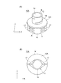
- the pouring spout 10 is the pouring spout 10 provided in the refill container 1 for injecting the content into the packaging container 30 and pouring out the content contained in the refill container 1.
- the spout 10 includes at least a bonded portion 11, a tubular portion 12, a flange portion 13, a flow path 14, and a closing member 20.
- the pasted portion 11 is a portion to be stuck to the bag body portion 5 that constitutes the refill container 1.
- the tubular portion 12 is a portion for pouring out contents.
- the flange portion 13 is a portion that projects outward at the boundary between the bonded portion 11 and the tubular portion 12.
- the flow path 14 is a part for passing the contents from the inside of the refill container 1 to the outside.
- the closing member 20 is a component for opening and closing the flow path 14.
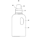
- the packaging container 30 includes a container body 31 and a pouring unit 40 for pouring out the contents contained in the container body 31.
- the pouring unit 40 has a nozzle 43 for pouring out the content and a peripheral wall portion 42 surrounding the periphery of the nozzle 43. Further, the most distant both ends in the horizontal direction of the flange portion 13 are slightly outwardly protruded from the facing portions of the peripheral wall portion 42.
- ⁇ "Slightly protruding to the outside" means that the peripheral wall portion 42 does not significantly protrude from the facing portion. Specifically, the most distant end portions in the horizontal direction of the flange portion 13 are located outside the facing portions of the peripheral wall portion 42 by a range of 3 mm or more and 15 mm or less (the protrusion amount on one side).
- the nozzle 43 of the packaging container 30 can be accurately inserted into the pouring spout 10 of the refill container 1, and the flange is efficiently pressed to open the closing member.
- the pour spout 10 that can be hung on is provided with a unique effect.
- the refill container 1 in which the pouring spout 10 according to the present invention is used is mainly used as a container for refilling a packaging container 30 used separately from the refill container 1 with contents.
- the form and type of the refill container 1 are not particularly limited.
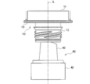
- FIG. 1 shows a standing pouch as an example of the refill container 1.
- This refill container 1 has a pair of opposed flat parts 2, a bottom part 3 that closes the bottom of the refill container 1, and a pouring spout 10 according to the present invention.
- both upper edges are sealed and both edges are sealed.
- the lower end edges of the pair of flat surface portions 2 are sealed to the end edge portions of the bottom surface portion 3 that face the lower end edges of the respective flat surface portions 2.
- the bottom surface portion 3 is folded in two at the center fold 4, and the fold 4 is folded toward the upper side of the refill container 1.
- the bottom surface portion 3 is configured so that the bottom portion of the refill container 1 can be opened by expanding the bottom portion 3 in the direction in which the flat surface portion 2 of the refill container 1 is arranged.
- the spout 10 is attached to the upper edge of the refill container 1.
- the spout spout 10 includes a spout body 10 a and a cap 110 that opens and closes the tubular portion 12 of the spout spout 10.
- the spout 10 may be provided at a position on the upper part of the refill container 1 which is offset to the side in the width direction.
- the refill container 1 may be provided with a portion in which an upper edge and a side edge are connected by an inclined portion that is inclined, and the pouring spout 10 may be attached to the inclined portion.
- the refill container 1 is used as a container for transferring the contents to a packaging container 30 (see FIG. 6) prepared separately from the refill container 1.
- a packaging container 30 see FIG. 6
- the cap 110 closing the pouring spout 10 is removed and the refill container 1 is turned upside down. Then, the pouring spout 10 is pierced into the pouring unit 40 of the packaging container 30, and the contents are directly transferred from the refill container 1 to the packaging container 30. Note that this action will be described later in detail.
- the outer diameter of the flange portion 13A is formed in a circular shape.
- the pouring spout 10 includes a tubular portion 12, a flange portion 13A, a bonded portion 11 and a closing member 20.
- a flow path 14 is formed inside the tubular portion 12 and the bonded portion 11, and the contents can be poured out to the outside through the flow path 14.
- the tubular portion 12 is formed in a cylindrical shape and has a function of pouring out the contents of the refill container 1 to the outside. Inside the tubular portion 12, the flow path 14 is formed in a form extending in the axial direction L as described above.
- a threaded portion 18 is formed on the outer peripheral surface of the tubular portion 12. The threaded portion 18 is a portion into which the cap 110 is screwed by being engaged with a screw thread in the cap 110 for closing the tubular portion 12.
- a guide 19 is formed in the flow path 14 inside the tubular portion 12. The guide 19 is a component for fitting a slit formed in the nozzle 43 of the pouring unit 40 and guiding the nozzle in the axial direction L.
- the part to be bonded 11 is a part to be bonded to the bag body 5 of the refill container 1, and has an outer shape of a boat. That is, both side surfaces of the bonded portion 11 have the projecting portions 16 that project in a semicircular shape in the central portion of the X direction, which is one of the two orthogonal directions, and in the Y direction, which is the other direction. , Both ends in the X direction are tapered toward both ends, and both side faces are connected at both ends in the X direction. A plurality of protrusions 17 extending in the X direction are formed on each side surface of the overhanging portion 16.
- the protruding portion 17 projects outward from the outer peripheral surface of the tubular portion 12 and extends to the vicinity of the outer peripheral edge of the flange portion 13A. A space is provided between the protrusions 17.
- the protrusion 17 is a component for facilitating attachment of the spout spout 10 to the bag body 5.
- the closing member 20 is a component for opening and closing the flow path 14, and has a disc shape.
- the closing member 20 closes the flow path 14 by being fitted inside the flow path 14 on the first surface 21 on the one end A side of the tubular portion 12 in the axial direction L, that is, on the bonded portion 11 side.
- the closing member 20 that closes the flow path 14 moves from the second surface on the other end B side opposite to the first surface 21 on the one end A side in the axial direction L of the tubular portion 12 to the one end A side. It is configured to be removed from the flow path 14 by an external force applied toward it. Therefore, the diameter of the closing member 20 is formed to be the same as or slightly smaller than the inner diameter of the flow path 14.
- the closing member 20 is connected to the spout body 10 a by a connecting member 23.
- the connecting member 23 is made of resin and is in the shape of an elongated cord or a strip.
- the flange portion 13A is used when pushing the refill container 1 into the packaging container 30 with a finger when inserting the nozzle 43 of the dispensing unit 40 constituting the packaging container 30 into the flow passage 14 of the dispensing spout 10. It is a part.
- the flange portion 13A of the first embodiment has a circular outer shape. Since the outer shape of the flange portion 13A is circular, it is possible to push it with a finger at any position on both sides of the flange portion 13A with the tubular portion 12 interposed therebetween.
- the flange portion 13A is configured.
- the shape of the flange portion 13A is not limited to the circular shape, and may be an elliptical shape. When formed in an elliptical shape, the major axis direction is aligned with the X direction and the minor axis direction is aligned with the Y direction.
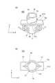
- the outer diameter of the flange portion 13B is formed in a quadrangle.
- the pouring spout 10 includes a tubular portion 12, a flange portion 13B, a bonded portion 11 and a closing member 20.
- a flow path 14 is formed inside the tubular portion 12 and the bonded portion 11, and the contents can be poured out to the outside through the flow path 14.
- the structure of the pouring spout 10 of the second embodiment is the same as the structure of the pouring spout 10 of the first embodiment except that the shape of the flange portion 13B is different. Therefore, the description of the structure other than the structure of the flange portion 13B will be given. Is omitted.
- the outer shape of the flange portion 13B of the second embodiment is polygonal.
- the outer shape of the flange portion 13B is formed in a rectangular shape.
- the major axis direction of the flange portion 13B coincides with the X direction, and the minor axis direction of the flange portion 13B coincides with the Y direction.
- the rectangular flange portion 13B shown in FIG. 4 is configured such that fingers can be attached to both sides of the flange portion 13B sandwiching the tubular portion 12 in the X direction and the flange portion 13B can be pushed in.
- the outer shape of the flange portion 13B of the second embodiment is not limited to a rectangle, and the shape is not limited as long as it is a polygon such as a triangle, a square, a pentagon, a hexagon, and an octagon.
- the outer shape of the flange portion 13B can be freely formed according to the function and design of the refill container 1.
- the flange portion 13C of the third embodiment has an arc portion 113 that is formed in an arc shape around the tubular portion 12 and projects outward, and a flange portion 13C that projects outward in one direction, the X direction. And a rectangular portion 213.
- the rectangular portion 213 is formed so that the dimension in the Y direction, which is the other direction, is smaller than the diameter of the tubular portion 12.
- the arcuate portion 113 surrounds both sides of the tubular portion 12 in the Y direction and projects outward in an arcuate shape.
- the rectangular portion 213 has a rectangular outer shape and projects outward from the tubular portion 12 in the X direction.
- the width of the rectangular portion 213, that is, the dimension in the Y direction is smaller than the diameter of the tubular portion 12, as shown in FIG. 5 (B).
- the flange portion 13C has a smaller area than the pouring spout 10 of the first embodiment and the pouring spout 10 of the second embodiment, and is closer to the tubular portion 12. Formed only in. Therefore, the position where the finger is applied is limited to the position close to the tubular portion 12.
- the pouring spout 10 described in the first embodiment, the second embodiment, and the third embodiment above is formed of a resin such as polyethylene, polypropylene, polyester, ethylene vinyl copolymer, or polyvinyl chloride.
- the pouring spout 10 is not limited in material as long as it can be molded.
- petroleum-derived, plant-derived, copolymers or blends thereof can be used as a raw material of the resin.
- the packaging container 30 is a container in which the contents contained in the refill container 1 are replenished and used.
- the packaging container 30 is made of, for example, resin.
- FIG. 6 shows an example of the packaging container 30.
- the packaging container 30 shown in FIG. 6 includes a container body 31 provided with a handle 32, and a pouring unit 40 for pouring out the contents contained in the container body 31.
- the packaging container 30 is used by taking out the contents transferred from the refill container 1 from the packaging container 30 when needed and in a required amount.
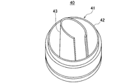
- the pouring unit 40 of the packaging container 30 is composed of a main body 41 and a cap 49 for opening and closing the main body 41.
- the main body portion 41 includes a peripheral wall portion 42 and a nozzle 43 arranged inside the peripheral wall portion 42.
- the peripheral wall portion 42 has a tubular shape and is hollow inside.
- the nozzle 43 is arranged at the center or substantially the center of the main body 41.
- the nozzle 43 is connected to the peripheral wall portion 42 and is integral with the peripheral wall portion 42.
- the nozzle 43 has a slit extending in the axial direction. Further, the nozzle 43 is configured to project upward from the main body portion 41, and the tip thereof is located above the upper end of the peripheral wall portion 42. Note that FIG. 7 shows one example of the shape of the nozzle 43, and the shape of the nozzle 43 is not particularly limited.
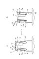
- FIGS. 8 and 9 show only the pouring spout 10 of the refill container 1 and the pouring unit 40 of the packaging container 30, and FIG. 9 shows the refill container 1 and the packaging container 1 in order to facilitate understanding of the action of the pouring spout 10.
- the container body 31 of 30 is not shown.
- the pouring spout 10 is attached to the refill container 1 shown in FIG. 1, and the pouring unit 40 is the pouring unit 40 shown in FIG. 7 provided in the packaging container 30 shown in FIG.
- the cap 110 is removed from the pouring spout 10, the refill container 1 is turned upside down, and the pouring spout 10 is positioned below the refill container 1. Since the flow path 14 of the pouring spout 10 is closed by the closing member 20, the contents contained in the refill container 1 will not spill out.
- the spout 10 is aligned with the position of the pouring unit 40 of the packaging container 30 with the cap 49 removed, and the nozzle 43 of the pouring unit 40 is set.
- the spout 10 is inserted into the flow path 14. That is, the nozzle 43 of the pouring unit 40 is inserted into the flow path 14 formed inside the tubular portion 12 of the pouring spout 10.
- fingers are attached to the flange portions 13 located on both sides of the tubular portion 12, and the flange portions 13 are pushed toward the pouring unit 40.
- the spout 10 is further pushed down toward the spout unit 40 with the nozzle 43 inserted in the tubular portion 12.
- the slits of the nozzle 43 sandwich the guide 19 of the spout 10 and the nozzle 43 is guided in the axial direction L.
- the tip of the nozzle 43 guided in the axial direction L pushes up the closing member 20.
- the closing member 20 is removed from the flow path 14 forming the inside of the tubular portion 12.
- the closing member 20 has the other end B side (the tip end side of the cylindrical pouring portion) opposite to the one end A side (the end side where the pasted part 11 is provided) in the axial direction L of the tubular portion 12. ), It is removed from the inner peripheral surface of the tubular portion 12.
- the closing member 20 since the closing member 20 is configured as a separate body from the spout body 10a, and is only fitted into the flow passage 14 forming the tubular portion 12, the flow passage 14 is closed.
- the nozzle 43 does not damage the closing member 20 itself, and is smoothly removed from the flow path 14. Therefore, no fragments are generated and only the contents are transferred to the packaging container 30.
- a finger can be attached and pushed in at any position as long as it is on both sides of the flange portion 13 with the tubular portion 12 sandwiched therebetween.
- (2) Flange The outer shape of the part 13 can be freely formed according to the function and design of the refill container 1, and (3) the inclination of the refill container 1 can be suppressed as much as possible, and the pouring unit 40 included in the packaging container 30. It is possible to obtain the effect that the nozzle 43 can be inserted into the flow path 14. As a result, it is possible to provide the pouring spout 10 in which the nozzle 43 of the packaging container 30 can be accurately inserted into the pouring spout 10 of the refill container 1.
Landscapes
- Engineering & Computer Science (AREA)
- Mechanical Engineering (AREA)
- Bag Frames (AREA)
Abstract
【課題】詰め替え容器の注出スパウトに包装容器のノズルを正確に挿入させることができる注出スパウトを提供する。 【解決手段】内容物を包装容器に注入するための詰め替え容器1に設けられ、詰め替え容器1に収容された内容物を注出するための注出スパウト10であって、詰め替え容器の袋本体部に貼り合わされる被貼り合わせ部11と、内容物を注出する筒状部12と、被貼り合わせ部11と筒状部12との境界で外側に向かって張り出すフランジ部13と、内容物を詰め替え容器の内部から外部に通すための流路14と、流路14を開閉するための閉鎖部材20とを少なくとも備え、フランジ部13の水平方向における最も離れた両端部が、包装容器を構成する注出ユニットの周壁部の対向する部位から若干外側にはみ出している、注出スパウトによって課題を解決する。
Description
本発明は、注出スパウトに関し、さらに詳しくは、フランジ部の形態に特徴を有する、詰め替え容器の注出スパウトに関する。
従来から、包装容器に内容物を補充したり、充填したりするための詰め替え容器がある。こうした詰め替え容器には、内容物を注出するための注出スパウトが取り付けられている。注出スパウトの形態は様々なものがあり、筒状をなす注ぎ口の基端部にフランジ部が設けられている形態やフランジ部が設けられていない形態等がある。
例えば、特許文献1で提案されている注出スパウトは、筒状の注ぎ口の基端部にフランジ部が設けられている。この注出スパウトは、逆さまにした可撓性袋のスパウトを繰り返し使用容器の口部に合わせて押し込むときに、スパウトの部分を挟み持つ指先でスパウトを押し下げ易くし、スパウトにおける上記閉鎖板の開き操作がスムーズに行なえるようにするために提案されている。こうした効果を得るために、同文献で提案されている注出スパウトは、スパウトの袋内側筒部と袋外側筒部との間のフランジ部に、可撓性袋の袋包材の重ね合わせ方向に沿った方向で相対する端部それぞれを外方に向けて延設して、袋内側筒部側の片面に指乗せできる延設部を設けている。
特許文献1で提案されている注出スパウトは、フランジ部が注出スパウトの中心側から外側に向かって大きく張り出している。そのため、フランジ部を指先で押し込むときに、一方の手の指先が注ぎ口の直近を押し込み、他方の手の指先がフランジ部の外周部の近傍を押し込む場合がある。その場合、詰め替え容器が傾いてしまい、詰め替え容器の注出スパウトに包装容器のノズルを正確に挿入させることができない。その結果、詰め替え容器の内容物がこぼれだしてしまうといった事態が生じてしまう。
本発明は、上記課題を解決するためになされたものであり、その目的は、詰め替え容器の注出スパウトに包装容器のノズルを正確に挿入させることができる注出スパウトを提供することにある。
上記課題を解決するための本発明に係る注出スパウトは、内容物を包装容器に注入するための詰め替え容器に設けられ、前記詰め替え容器に収容された内容物を注出するための注出スパウトであって、前記詰め替え容器を構成する袋本体部に貼り合わされる被貼り合わせ部と、前記内容物を注出する筒状部と、前記被貼り合わせ部と前記筒状部との境界部で外側に向かって張り出すフランジ部と、前記内容物を前記詰め替え容器の内部から外部に通すための流路と、前記流路を開閉するための閉鎖部材とを少なくとも備え、前記包装容器は、容器本体と、前記容器本体に収容された内容物を注出するための注出ユニットと、を備え、前記注出ユニットは、内容物を注出するノズルと、前記ノズルの周囲を囲む周壁部とを有し、前記フランジ部の水平方向における最も離れた両端部が、前記周壁部の対向する部位から若干外側にはみ出している、ことを特徴とする。
この発明によれば、フランジ部の水平方向における最も離れた両端部が、周壁部の対向する部位から若干外側にはみ出しているので、筒状部の両側に添えられる指の中心からの位置が同じか略同じになる。そのため、筒状部の両側に添えられた指で注出スパウトを押し込む力を同じか略同じにすることができる。たとえ、筒状部の両側に添えられた指で注出スパウトを押し込む力が異なっていたとしても、筒状部の近傍を押し込んでいるので、詰め替え容器が傾いてしまうことを抑制することがでる。そのため、包装容器のノズルを正確に注出スパウトの流路に挿入することができ、詰め替え容器の内容物をこぼすことなく包装容器に注入することができる。
本発明に係る注出スパウトにおいて、前記被貼り合わせ部は、直交する2方向のうち、一方の方向では、前記貼り合わせ部の前記一方の方向における中心から両側に向かって先細りに形成され、他方の方向では、外形が円弧状をなして外側に突出している。
この発明によれば、被貼り合わせ部における直交する2方向のうち、一方の方向では、貼り合わせ部の前記一方の方向における中心から両側に向かって先細りに形成され、他方の方向では、外形が円弧状をなして外側に突出しているので、注出スパウトと袋本体部とが貼り合わされる部位において、注出スパウトの流路を確保することができる。そのため、詰め替え容器から包装容器に内容物を円滑に移し替えることができる。
本発明に係る注出スパウトにおいて、前記フランジ部の外形が、円形、楕円形、多角形又はそれらの組み合わせ形状である。
この発明によれば、フランジ部の外形が、円形、楕円形、多角形又はそれらの組合せ形状をなしているので、個々の詰め替え容器に応じたデザインのフランジ部を選定することができる。
本発明に係る注出スパウトにおいて、前記フランジ部は、前記筒状部の周囲で円弧状をなして外側に張り出す円弧部と、前記一方の方向で外側に張り出す張り出し部とを備え、前記張り出し部における前記他方の方向の寸法が前記筒状部の直径よりも小さく形成されている。
この発明によれば、上述した2方向のうち一方の方向で外側に張り出す張り出し部を備え、張り出し部における他方の方向の寸法が筒状部の直径よりも小さく形成されているので、指を添えるフランジ部の位置が限定される。その結果、フランジ部を押し込んで、包装容器のノズルを流路に挿入させるときに、詰め替え容器の体勢を維持させ、傾くことを抑制し、より正確に挿入させることができる。
本発明によれば、詰め替え容器の注出スパウトに包装容器のノズルを正確に挿入させることができる注出スパウトを提供することができる。
以下、図面を参照しつつ、本発明の実施形態について説明する。本発明は、以下に説明する実施形態及び図面に記載した形態と同じ技術的思想の発明を含むものであり、本発明の技術的範囲は実施形態の記載や図面の記載のみに限定されるものでない。
[基本構成]
本発明に係る注出スパウト10は、内容物を包装容器30に注入するための詰め替え容器1に設けられ、詰め替え容器1に収容された内容物を注出するための注出スパウト10である。注出スパウト10は、例えば、図2に示すように、被貼り合わせ部11、筒状部12、フランジ部13、流路14、及び閉鎖部材20を少なくとも備えている。被貼り合わせ部11は、詰め替え容器1を構成する袋本体部5に貼り合わされる部位である。筒状部12は、内容物を注出するための部位である。フランジ部13は、被貼り合わせ部11と筒状部12との境界部で外側に向かって張り出す部位である。流路14は、内容物を詰め替え容器1の内部から外部に通すための部位である。そして、閉鎖部材20は、流路14を開閉するための構成要素である。
本発明に係る注出スパウト10は、内容物を包装容器30に注入するための詰め替え容器1に設けられ、詰め替え容器1に収容された内容物を注出するための注出スパウト10である。注出スパウト10は、例えば、図2に示すように、被貼り合わせ部11、筒状部12、フランジ部13、流路14、及び閉鎖部材20を少なくとも備えている。被貼り合わせ部11は、詰め替え容器1を構成する袋本体部5に貼り合わされる部位である。筒状部12は、内容物を注出するための部位である。フランジ部13は、被貼り合わせ部11と筒状部12との境界部で外側に向かって張り出す部位である。流路14は、内容物を詰め替え容器1の内部から外部に通すための部位である。そして、閉鎖部材20は、流路14を開閉するための構成要素である。
一方、包装容器30は、容器本体31と、容器本体31に収容された内容物を注出するための注出ユニット40と、を備えている。注出ユニット40は、内容物を注出するノズル43と、ノズル43の周囲を囲む周壁部42とを有している。そして、フランジ部13の水平方向における最も離れた両端部が、周壁部42の対向する部位から若干外側にはみ出している。
「若干外側にはみ出している」とは、周壁部42の対向する部位から大きく突出していないことを意味する。具体的に、フランジ部13の水平方向における最も離れた両端部は、周壁部42の対向する部位から3mm以上、15mm以下の範囲だけ外側に位置する(片側のはみだし量である)。
本発明に係る注出スパウト10によれば、詰め替え容器1の注出スパウト10に包装容器30のノズル43を正確に挿入させることができ、かつ、閉鎖部材を開封するために効率よくフランジに押圧を掛けることができる注出スパウト10を提供することができるといた特有の効果を奏する。
以下、注出スパウト10が用いられる詰め替え容器1の概要、注出スパウト10の具体的な構成、詰め替え容器1に収容された内容物が補充されて用いられる包装容器30の概要、及び注出スパウト10の作用について説明する。
[注出スパウトが用いられる詰め替え容器]
本発明に係る注出スパウト10が用いられる詰め替え容器1は、詰め替え容器1とは別に使用される包装容器30に内容物を補充するための容器として主に用いられる。詰め替え容器1の形態や種類は特に限定されない。図1には、詰め替え容器1の一例としてのスタンディングパウチを示している。この詰め替え容器1は、対向する一対の平面部2と、詰め替え容器1の底部を閉じている底面部3と、本発明に係る注出スパウト10と、を有している。
本発明に係る注出スパウト10が用いられる詰め替え容器1は、詰め替え容器1とは別に使用される包装容器30に内容物を補充するための容器として主に用いられる。詰め替え容器1の形態や種類は特に限定されない。図1には、詰め替え容器1の一例としてのスタンディングパウチを示している。この詰め替え容器1は、対向する一対の平面部2と、詰め替え容器1の底部を閉じている底面部3と、本発明に係る注出スパウト10と、を有している。
平面部2は、上端縁同士がシールされると共に、両側端縁同士がシールされている。一対の平面部2の下端縁は、底面部3における各平面部2の下端縁に対向する端縁部にそれぞれシールされている。底面部3は、中心の折目4で二つ折りされており、折目4が詰め替え容器1の上側に向けて折り込まれている。底面部3は、折り込まれた形態から詰め替え容器1の平面部2が配置されている方向に広げられることによって、詰め替え容器1の底部を広げることができるように構成されている。
本発明に係る注出スパウト10は、詰め替え容器1の上端縁に取り付けられている。注出スパウト10は、スパウト本体10aと注出スパウト10の筒状部12を開閉させるキャップ110とにより構成されている。なお、本実施形態では、注出スパウト10が詰め替え容器1の上部中央に取り付けられた場合を一例として取り上げている。ただし、特に図面には示していないが、注出スパウト10が詰め替え容器1の上部において、幅方向の側部にずれた位置に設けても良い。また、詰め替え容器1に上端縁と側端縁とが斜めに傾斜する傾斜部により連絡された部位を設け、傾斜部に注出スパウト10を取り付けてもよい。
詰め替え容器1は、この詰め替え容器1とは別に用意された包装容器30(図6を参照。)に内容物を移し替えるための容器として用いられる。内容物を包装容器30に移し替える場合には、注出スパウト10を閉じているキャップ110を取り外し、詰め替え容器1の上下を逆さまにする。そして、注出スパウト10を包装容器30の注出ユニット40に突き刺して、詰め替え容器1から直に内容物を包装容器30に移し替える。なお、この作用は、後ほど詳細に説明する。
[注出スパウトの第1実施形態]
第1実施形態の注出スパウト10は、図3に示すように、フランジ部13Aの外径が円形に形成されている。注出スパウト10は、筒状部12、フランジ部13A、被貼り合わせ部11及び閉鎖部材20によって構成されている。筒状部12及び被貼り合わせ部11の内部には流路14が形成されており、流路14を通して内容物を外部に注出することができるように構成されている。
第1実施形態の注出スパウト10は、図3に示すように、フランジ部13Aの外径が円形に形成されている。注出スパウト10は、筒状部12、フランジ部13A、被貼り合わせ部11及び閉鎖部材20によって構成されている。筒状部12及び被貼り合わせ部11の内部には流路14が形成されており、流路14を通して内容物を外部に注出することができるように構成されている。
筒状部12は、円筒状に形成されており、詰め替え容器1の内容物を外部に注出する機能を有している。筒状部12の内側には、上述したように流路14が軸方向Lに延びる形態で形成されている。一方、筒状部12の外周面にはねじ部18が形成されている。このねじ部18は、筒状部12を閉鎖するためのキャップ110内のねじ山と係り合わされてキャップ110がねじ込まれる部位である。筒状部12の内部の流路14には、ガイド19が形成されている。ガイド19は、注出ユニット40のノズル43に形成されたスリットをはめ込ませ、ノズルを軸方向Lに案内するための構成部である。
被貼り合わせ部11は、詰め替え容器1の袋本体部5に貼り合わされる部位であって、外形が舟形をなしている。すなわち、被貼り合わせ部11の両側面は、直交する2方向のうち、一方の方向であるX方向の中心部で他方の方向であるY方向に半円状に張り出す張り出し部16を有し、X方向の両端部は、両端側に向かって先細りをなし、両側面がX方向の両端部で接続されている。張り出し部16の各側面部には、X方向に延びる複数の突起部17がそれぞれ形成されている。突起部17は、筒状部12の外周面から外側に向かって突出し、フランジ部13Aの外周縁の近傍まで延びている。突起部17同士の間は空間である。この突起部17は、袋本体部5に対し、注出スパウト10を貼り合わせし易くするための構成部である。
閉鎖部材20は、流路14を開閉するための構成要素であって、円盤状をなしている。閉鎖部材20は、筒状部12の軸方向Lの一端A側の第1面21、すなわち、被貼り合わせ部11側で流路14の内側にはめ込まれることにより、流路14を閉鎖する。一方、流路14を閉鎖している閉鎖部材20は、筒状部12の軸方向Lの一端A側の第1面21とは逆側の他端B側の第2面から一端A側に向けて加えられる外力によって流路14から取り外されるように構成されている。そのため、閉鎖部材20の直径は、流路14の内径と同じか又は若干小さく形成されている。こうした閉鎖部材20は、連結部材23によってスパウト本体10aにつながれている。連結部材23は、樹脂で構成されており、細長い紐状又は帯状をなしている。
フランジ部13Aは、注出スパウト10の流路14に包装容器30を構成する注出ユニット40のノズル43を挿入するときに、指を添えて、詰め替え容器1を包装容器30に押し込むとき利用する部位である。第1実施形態のフランジ部13Aは、その外形が円形をなしている。フランジ部13Aの外形が円形をなしているので、筒状部12を間に挟んだ、フランジ部13Aの両側であれば、どの位置であっても、指を添えて押し込むことができるように、フランジ部13Aが構成されている。なお、フランジ部13Aの形状は、円形であることには限定されず、楕円形に形成してもよい。楕円形に形成した場合、長軸方向はX方向に一致させ、短軸方向はY方向に一致させる。
[注出スパウトの第2実施形態]
第2実施形態の注出スパウト10は、図4に示すように、フランジ部13Bの外径が四角形に形成されている。注出スパウト10は、筒状部12、フランジ部13B、被貼り合わせ部11及び閉鎖部材20によって構成されている。筒状部12及び被貼り合わせ部11の内部には流路14が形成されており、流路14を通して内容物を外部に注出することができるように構成されている。なお、第2実施形態の注出スパウト10の構成は、フランジ部13Bの形状が異なるだけで、第1実施形態の注出スパウト10の構成と同様なので、フランジ部13Bの構成以外の構成の説明は省略する。
第2実施形態の注出スパウト10は、図4に示すように、フランジ部13Bの外径が四角形に形成されている。注出スパウト10は、筒状部12、フランジ部13B、被貼り合わせ部11及び閉鎖部材20によって構成されている。筒状部12及び被貼り合わせ部11の内部には流路14が形成されており、流路14を通して内容物を外部に注出することができるように構成されている。なお、第2実施形態の注出スパウト10の構成は、フランジ部13Bの形状が異なるだけで、第1実施形態の注出スパウト10の構成と同様なので、フランジ部13Bの構成以外の構成の説明は省略する。
第2実施形態のフランジ部13Bは、その外形が多角形をなしている。図4に示した例では、フランジ部13Bの外形が長方形に形成されている。フランジ部13Bの長軸方向はX方向に一致し、フランジ部13Bの短軸方向はY方向に一致している。図4に示した長方形のフランジ部13Bでは、X方向において、筒状部12を間に挟んだフランジ部13Bの両側に指を添え、フランジ部13Bを押し込むことができるように構成されている。第2実施形態のフランジ部13Bの外形は、長方形であることには限定されず、三角形、正方形、五角形、六角形、八角形等、多角形であれば、その形状に限定はない。フランジ部13Bの外形は、詰め替え容器1の機能やデザイン等に応じ、自由に形成することができる。
[注出スパウトの第3実施形態]
第3実施形態のフランジ部13Cは、図5に示すように、筒状部12の周囲で円弧状をなして外側に張り出す円弧部113と、一方の方向であるX方向の外側に張り出す矩形部213とを備えている。そして、矩形部213は、他方の方向であるY方向の寸法が筒状部12の直径よりも小さく形成されている。円弧部113は、筒状部12におけるY方向の両側の周囲を囲むようにして、外側に向かって円弧状に張り出している。一方、矩形部213は外形が矩形をなしており、X方向に向かって筒状部12から外側に張り出している。矩形部213の幅、すなわちY方向の寸法は、図5(B)に示すように、筒状部12の直径よりも小さく形成されている。
第3実施形態のフランジ部13Cは、図5に示すように、筒状部12の周囲で円弧状をなして外側に張り出す円弧部113と、一方の方向であるX方向の外側に張り出す矩形部213とを備えている。そして、矩形部213は、他方の方向であるY方向の寸法が筒状部12の直径よりも小さく形成されている。円弧部113は、筒状部12におけるY方向の両側の周囲を囲むようにして、外側に向かって円弧状に張り出している。一方、矩形部213は外形が矩形をなしており、X方向に向かって筒状部12から外側に張り出している。矩形部213の幅、すなわちY方向の寸法は、図5(B)に示すように、筒状部12の直径よりも小さく形成されている。
第3実施形態の注出スパウト10は、フランジ部13Cが、第1実施形態の注出スパウト10及び第2実施形態の注出スパウト10に比べて面積が小さく、且つ筒状部12により近い領域のみに形成されている。そのため、指を添える位置が筒状部12に近い位置に限定される。その結果、詰め替え容器1を包装容器30の注出ユニット40に向けて押し込むときに、X方向において、筒状部12の一方の片側に添えた指で押し込む力と、他方の片側に添えた指で押し込む力とが異なっていた場合でも、詰め替え容器1の傾きを極力抑制することができ、包装容器30が備える注出ユニット40のノズル43を流路14内に挿入させることができる。
以上、第1実施形態、第2実施形態、第3実施形態で説明した注出スパウト10は、ポリエチレン、ポリプロピレン、ポリエステル、エチレンビニル共重合体、ポリ塩化ビニル等の樹脂で形成されている。ただし、注出スパウト10は、成形加工可能なものであれば材料の制限はない。また、樹脂の原料としては石油由来、植物由来、それらの共重合、ブレンドなどを使用することができる。
[包装容器]
包装容器30は、詰め替え容器1に収容された内容物が補充されて使用される容器である。包装容器30は、例えば樹脂等で構成される。図6は、包装容器30の一例を示している。図6に示した包装容器30は、取っ手32が設けられた容器本体31と、容器本体31に収容された内容物を注出するための注出ユニット40とにより構成されている。この包装容器30は、詰め替え容器1から移された内容物を必要なときに必要な量だけ包装容器30から取り出して用いられる。
包装容器30は、詰め替え容器1に収容された内容物が補充されて使用される容器である。包装容器30は、例えば樹脂等で構成される。図6は、包装容器30の一例を示している。図6に示した包装容器30は、取っ手32が設けられた容器本体31と、容器本体31に収容された内容物を注出するための注出ユニット40とにより構成されている。この包装容器30は、詰め替え容器1から移された内容物を必要なときに必要な量だけ包装容器30から取り出して用いられる。
包装容器30の注出ユニット40は、本体部41と本体部41を開閉するためのキャップ49とにより構成されている。本体部41は、図7に示すように、周壁部42とこの周壁部42の内側に配置されたノズル43とを備えている。周壁部42は筒状をなし、内側は空洞になっている。
ノズル43は、本体部41の中央又は略中央の位置に配置されている。ノズル43は、周壁部42とつながれており周壁部42と一体をなしている。ノズル43には、図7に示すように、軸方に延びるスリットが形成されている。また、ノズル43は、本体部41から上側に向かって突出し、その先端が、周壁部42の上端よりも上側に位置するように構成されている。なお、図7は、ノズル43の形状の1つの例を示しており、ノズル43の形状は特に限定されない。
[内容物補充の手順及び注出スパウトの作用]
図8及び図9を参照し、詰め替え容器1に収容されている内容物を包装容器30に補充する手順と、本実施形態の注出スパウト10の作用について説明する。なお、図8は、詰め替え容器1の注出スパウト10と包装容器30の注出ユニット40だけを示し、図9は、注出スパウト10の作用をわかりやすくするために、詰め替え容器1及び包装容器30の容器本体31については、図示していない。ただし、注出スパウト10は、図1に示した詰め替え容器1に取り付けられ、注出ユニット40は、図6に示した包装容器30に設けられた図7に示す注出ユニット40である。
図8及び図9を参照し、詰め替え容器1に収容されている内容物を包装容器30に補充する手順と、本実施形態の注出スパウト10の作用について説明する。なお、図8は、詰め替え容器1の注出スパウト10と包装容器30の注出ユニット40だけを示し、図9は、注出スパウト10の作用をわかりやすくするために、詰め替え容器1及び包装容器30の容器本体31については、図示していない。ただし、注出スパウト10は、図1に示した詰め替え容器1に取り付けられ、注出ユニット40は、図6に示した包装容器30に設けられた図7に示す注出ユニット40である。
まず、図8に示すように、注出スパウト10からキャップ110を取り外し、詰め替え容器1の上下を逆にして、詰め替え容器1の下側に注出スパウト10を位置させる。注出スパウト10の流路14は、閉鎖部材20により閉じられているので、詰め替え容器1に収容されている内容物がこぼれ出すことはない。
次に、図8及び図9(A)に示すように、注出スパウト10を、キャップ49が取り外された包装容器30の注出ユニット40の位置に一致させ、注出ユニット40のノズル43を注出スパウト10の流路14に挿入させる。すなわち、注出スパウト10を構成する筒状部12の内側に構成された流路14に注出ユニット40のノズル43を挿入させる。その際、図8に示すように、筒状部12の両側に位置するフランジ部13に指を添え、フランジ部13を注出ユニット40に向けて押し込む。
次いで、筒状部12にノズル43を挿入させた状態で注出スパウト10を注出ユニット40側にさらに押し下げる。注出スパウト10を押し下げると、ノズル43のスリットが注出スパウト10のガイド19を挟み込み、ノズル43が軸方向Lに案内される。そして、軸方向Lに案内されたノズル43の先端が閉鎖部材20を押し上げる。その結果、図9(B)に示すように、閉鎖部材20が筒状部12の内側を構成している流路14から取り外される。すなわち、閉鎖部材20は、筒状部12の軸方向Lにおける一端A側(被貼り合わせ部11が設けられた端部側)とは逆側の他端B側(円筒注出部の先端側)から加えられる外力によって筒状部12の内周面から取り外される。この際、閉鎖部材20は、スパウト本体10aとは別体として構成されており、且つ、筒状部12を構成する流路14にはめ込まれることにより流路14を閉じているだけであるので、ノズル43が閉鎖部材20それ自体を破壊してしまうことがなく、円滑に流路14から取り外される。そのため、破片が発生せず、包装容器30に内容物だけが移される。
また、図9(B)に示すように、ノズル43が筒状部12の内部に挿入され、閉鎖部材20がスパウト本体10aか外されたとき、筒状注出体の先端部がノズル43の外周面に接触する。そのため、詰め替え容器1から注出された内容物は、ノズル43の外側に漏れ出さないで、ノズル43を通して包装容器30に移される。
以上、本発明によれば、(1)筒状部12を間に挟んだ、フランジ部13の両側であれば、どの位置であっても、指を添えて押し込むことができる、(2)フランジ部13の外形は、詰め替え容器1の機能やデザイン等に応じ、自由に形成することができる、(3)詰め替え容器1の傾きを極力抑制することができ、包装容器30が備える注出ユニット40のノズル43を流路14内に挿入させることができるといった効果を奏することができる。その結果、詰め替え容器1の注出スパウト10に包装容器30のノズル43を正確に挿入させることができる注出スパウト10を提供することを可能にしている。
1 詰め替え容器
2 平面部
3 底面部
4 折目
5 袋本体部
10 注出スパウト
10a スパウト本体
11 被貼り合わせ部
12 筒状部
13,13A,13B,13C フランジ部
14 流路
16 張り出し部
17 突起部
18 ねじ部
19 ガイド
20 閉鎖部材
21 第1面
22 第2面
23 連結部材
30 包装容器
31 容器本体
32 取っ手
40 注出ユニット
41 本体部
42 周壁部
43 ノズル
49 キャップ
110 キャップ
113 円弧部
213 矩形部
2 平面部
3 底面部
4 折目
5 袋本体部
10 注出スパウト
10a スパウト本体
11 被貼り合わせ部
12 筒状部
13,13A,13B,13C フランジ部
14 流路
16 張り出し部
17 突起部
18 ねじ部
19 ガイド
20 閉鎖部材
21 第1面
22 第2面
23 連結部材
30 包装容器
31 容器本体
32 取っ手
40 注出ユニット
41 本体部
42 周壁部
43 ノズル
49 キャップ
110 キャップ
113 円弧部
213 矩形部
Claims (4)
- 内容物を包装容器に注入するための詰め替え容器に設けられ、前記詰め替え容器に収容された内容物を注出するための注出スパウトであって、
前記詰め替え容器を構成する袋本体部に貼り合わされる被貼り合わせ部と、前記内容物を注出する筒状部と、前記被貼り合わせ部と前記筒状部との境界部で外側に向かって張り出すフランジ部と、前記内容物を前記詰め替え容器の内部から外部に通すための流路と、前記流路を開閉するための閉鎖部材とを少なくとも備え、
前記包装容器は、容器本体と、前記容器本体に収容された内容物を注出するための注出ユニットと、を備え、
前記注出ユニットは、内容物を注出するノズルと、前記ノズルの周囲を囲む周壁部とを有し、
前記フランジ部の水平方向における最も離れた両端部が、前記周壁部の対向する部位から若干外側にはみ出している、ことを特徴とする注出スパウト。 - 前記被貼り合わせ部は、直交する2方向のうち、一方の方向では、前記貼り合わせ部の前記一方の方向における中心から両側に向かって先細りに形成され、他方の方向では、外形が円弧状をなして外側に突出している、請求項1に記載の注出スパウト。
- 前記フランジ部の外形が、円形、楕円形、多角形又はそれらの組合せ形状である、請求項1又は2に記載の注出スパウト。
- 前記フランジ部は、前記筒状部の周囲で円弧状をなして外側に張り出す円弧部と、前記一方の方向で外側に張り出す張り出し部とを備え、前記張り出し部における前記他方の方向の寸法が前記筒状部の直径よりも小さく形成されている、請求項1又は2に記載の注出スパウト。
Priority Applications (5)
| Application Number | Priority Date | Filing Date | Title |
|---|---|---|---|
| CN201980071346.1A CN112955382B (zh) | 2018-10-30 | 2019-10-24 | 倒出嘴 |
| SG11202104286WA SG11202104286WA (en) | 2018-10-30 | 2019-10-24 | Pouring spout |
| EP19878440.7A EP3875389A4 (en) | 2018-10-30 | 2019-10-24 | POUR SPOUT |
| US17/289,942 US11623807B2 (en) | 2018-10-30 | 2019-10-24 | Pouring spout |
| KR1020217010197A KR20210083253A (ko) | 2018-10-30 | 2019-10-24 | 주출 스파우트 |
Applications Claiming Priority (2)
| Application Number | Priority Date | Filing Date | Title |
|---|---|---|---|
| JP2018203604A JP7174593B2 (ja) | 2018-10-30 | 2018-10-30 | 注出スパウト及び詰め替え容器から包装容器への内容物補充方法 |
| JP2018-203604 | 2018-10-30 |
Publications (1)
| Publication Number | Publication Date |
|---|---|
| WO2020090620A1 true WO2020090620A1 (ja) | 2020-05-07 |
Family
ID=70464494
Family Applications (1)
| Application Number | Title | Priority Date | Filing Date |
|---|---|---|---|
| PCT/JP2019/041728 WO2020090620A1 (ja) | 2018-10-30 | 2019-10-24 | 注出スパウト |
Country Status (7)
| Country | Link |
|---|---|
| US (1) | US11623807B2 (ja) |
| EP (1) | EP3875389A4 (ja) |
| JP (1) | JP7174593B2 (ja) |
| KR (1) | KR20210083253A (ja) |
| CN (1) | CN112955382B (ja) |
| SG (1) | SG11202104286WA (ja) |
| WO (1) | WO2020090620A1 (ja) |
Families Citing this family (1)
| Publication number | Priority date | Publication date | Assignee | Title |
|---|---|---|---|---|
| JP7476869B2 (ja) * | 2021-11-22 | 2024-05-01 | 東洋製罐株式会社 | スパウト付きパウチ |
Citations (4)
| Publication number | Priority date | Publication date | Assignee | Title |
|---|---|---|---|---|
| JP2004231217A (ja) * | 2003-01-29 | 2004-08-19 | Fuji Seal Inc | パウチ容器 |
| JP2011173615A (ja) * | 2010-02-24 | 2011-09-08 | Japan Crown Cork Co Ltd | 合成樹脂から一体に成形されたスパウト |
| JP2015013655A (ja) | 2013-07-03 | 2015-01-22 | 凸版印刷株式会社 | スパウトとこのスパウトを取り付けたスタンディングパウチ |
| JP2018095258A (ja) * | 2016-12-08 | 2018-06-21 | 藤森工業株式会社 | 容器の注出用スパウト |
Family Cites Families (31)
| Publication number | Priority date | Publication date | Assignee | Title |
|---|---|---|---|---|
| DE29509118U1 (de) * | 1995-06-02 | 1995-08-17 | Georg Menshen Gmbh & Co Kg | Kunststoff-Ausgießeinschweißteil für Kunststoff-Behälter |
| NL1006636C2 (nl) * | 1997-07-21 | 1999-01-25 | Itsac Nv | Verbindingssamenstel voor een fluïdumverbinding. |
| NL1011960C2 (nl) * | 1999-05-04 | 2000-11-07 | Itsac Nv | Houder, in het bijzonder een flexibele houder, met een afsluitbare opening en werkwijze voor het vullen van een dergelijke houder. |
| US6612466B1 (en) * | 2000-08-21 | 2003-09-02 | Illinois Tool Works Inc. | Thin wall fitment for spouted pouch |
| US6860406B2 (en) * | 2001-08-13 | 2005-03-01 | Illinois Tool Works Inc. | Flexible pouch fitment structure |
| AU2002362269A1 (en) * | 2001-09-10 | 2003-03-24 | Jung-Min Lee | Spout assembly |
| JP4352671B2 (ja) * | 2002-09-06 | 2009-10-28 | 東洋製罐株式会社 | 手放し詰め替え容器 |
| JP4424538B2 (ja) * | 2004-04-30 | 2010-03-03 | 株式会社吉野工業所 | 薄肉容器 |
| EP1676784A1 (en) * | 2004-12-29 | 2006-07-05 | The Procter & Gamble Company | Flexible container containing a liquid product, and a process for making a liquid-filled, flexible container |
| FR2933675B1 (fr) * | 2008-07-08 | 2010-08-13 | Seaquist General Plastics | Element de fermeture d'un recipient en particulier fait dans un materiau de type feuille |
| ES2310499B1 (es) * | 2008-07-18 | 2010-01-05 | Volpak, S.A.U. | "boca de descarga para bolsas flexibles". |
| JP5489703B2 (ja) * | 2009-12-25 | 2014-05-14 | 株式会社吉野工業所 | 詰め替え容器 |
| JP5523899B2 (ja) * | 2010-03-31 | 2014-06-18 | 株式会社吉野工業所 | 詰替え用ノズル |
| US20120024858A1 (en) * | 2010-07-29 | 2012-02-02 | Ecolab Usa Inc. | Vented flexible fitment |
| US20130319970A1 (en) * | 2010-12-27 | 2013-12-05 | Kao Corporation | Package |
| DE202011001356U1 (de) * | 2011-01-11 | 2012-04-12 | Pöppelmann Holding GmbH & Co. KG | Ausgießer und Behältnis mit einem solchen |
| US9617054B2 (en) * | 2014-06-13 | 2017-04-11 | Decko Products, Inc. | Dual thread nozzle and cap assembly for dispensing pouch |
| TW201713575A (zh) * | 2015-09-30 | 2017-04-16 | 陶氏全球科技有限責任公司 | 具有乙烯/α-烯烴多嵌段共聚物的配件 |
| WO2017135958A1 (en) * | 2016-02-04 | 2017-08-10 | Silgan White Cap LLC | Container assembly with vent |
| US10138448B2 (en) * | 2016-04-11 | 2018-11-27 | Veltek Associates, Inc | Deactivation wipe kit |
| AR108467A1 (es) * | 2016-05-27 | 2018-08-22 | Dow Global Technologies Llc | Accesorio con componente de mezcla y contenedor flexible con el mismo |
| NL2017333B1 (en) * | 2016-08-18 | 2018-02-23 | Scholle Ipn Ip Bv | A closure assembly and container provided with such a closure assembly |
| JP6236139B1 (ja) * | 2016-12-08 | 2017-11-22 | 藤森工業株式会社 | 詰め替え容器の注出用スパウト及び包装容器の注出ユニットとの連結構造 |
| JP6194132B1 (ja) * | 2017-03-21 | 2017-09-06 | 藤森工業株式会社 | 容器の注出用スパウト |
| DE102017009693A1 (de) * | 2017-10-13 | 2019-04-18 | Georg Menshen Gmbh & Co. Kg | Ausgießer für Beutelverpackungen |
| IT201700120600A1 (it) * | 2017-10-24 | 2019-04-24 | Guala Pack Spa | Metodo di riempimento di un imballo a parete sottile munito di cannuccia |
| US11414248B2 (en) * | 2017-12-19 | 2022-08-16 | Dariusz Jerzy Krajewski | Dispenser with a membrane for sachets |
| US10442582B1 (en) * | 2018-08-14 | 2019-10-15 | Phoenix Closures, Inc. | Spout fitment apparatus for a flexible container |
| JP7193305B2 (ja) * | 2018-10-30 | 2022-12-20 | 藤森工業株式会社 | 注出スパウト |
| CN114585569A (zh) * | 2019-10-01 | 2022-06-03 | 奥布里斯特封闭瑞士有限公司 | 袋封闭件 |
| US11673727B2 (en) * | 2021-03-03 | 2023-06-13 | Scholle Ipn Corporation | Dispensing system for a flexible bag, flexible bag assembly |
-
2018
- 2018-10-30 JP JP2018203604A patent/JP7174593B2/ja active Active
-
2019
- 2019-10-24 SG SG11202104286WA patent/SG11202104286WA/en unknown
- 2019-10-24 KR KR1020217010197A patent/KR20210083253A/ko not_active Application Discontinuation
- 2019-10-24 CN CN201980071346.1A patent/CN112955382B/zh active Active
- 2019-10-24 EP EP19878440.7A patent/EP3875389A4/en active Pending
- 2019-10-24 WO PCT/JP2019/041728 patent/WO2020090620A1/ja unknown
- 2019-10-24 US US17/289,942 patent/US11623807B2/en active Active
Patent Citations (4)
| Publication number | Priority date | Publication date | Assignee | Title |
|---|---|---|---|---|
| JP2004231217A (ja) * | 2003-01-29 | 2004-08-19 | Fuji Seal Inc | パウチ容器 |
| JP2011173615A (ja) * | 2010-02-24 | 2011-09-08 | Japan Crown Cork Co Ltd | 合成樹脂から一体に成形されたスパウト |
| JP2015013655A (ja) | 2013-07-03 | 2015-01-22 | 凸版印刷株式会社 | スパウトとこのスパウトを取り付けたスタンディングパウチ |
| JP2018095258A (ja) * | 2016-12-08 | 2018-06-21 | 藤森工業株式会社 | 容器の注出用スパウト |
Non-Patent Citations (1)
| Title |
|---|
| See also references of EP3875389A4 |
Also Published As
| Publication number | Publication date |
|---|---|
| EP3875389A4 (en) | 2022-07-06 |
| EP3875389A1 (en) | 2021-09-08 |
| JP7174593B2 (ja) | 2022-11-17 |
| CN112955382B (zh) | 2023-02-03 |
| KR20210083253A (ko) | 2021-07-06 |
| US20220009688A1 (en) | 2022-01-13 |
| US11623807B2 (en) | 2023-04-11 |
| CN112955382A (zh) | 2021-06-11 |
| SG11202104286WA (en) | 2021-06-29 |
| JP2020070035A (ja) | 2020-05-07 |
Similar Documents
| Publication | Publication Date | Title |
|---|---|---|
| WO2018105687A1 (ja) | 詰め替え容器の注出用スパウト及び包装容器の注出ユニットとの連結構造 | |
| JP6194132B1 (ja) | 容器の注出用スパウト | |
| JP5756357B2 (ja) | 詰替え用軟包装容器 | |
| JP6183847B2 (ja) | 詰替え容器用栓体 | |
| WO2020090620A1 (ja) | 注出スパウト | |
| JP6960731B2 (ja) | 容器の注出用スパウト | |
| JP5121144B2 (ja) | パウチ用口栓、口栓付きパウチ、および包装体 | |
| JP2010247898A (ja) | 詰替え容器用口栓 | |
| JP5365283B2 (ja) | 詰替え容器 | |
| JP5961547B2 (ja) | 詰め替え容器 | |
| JP5977641B2 (ja) | 詰替え容器用栓部材 | |
| JP2010222022A (ja) | 注出具 | |
| JP5730011B2 (ja) | 詰替え容器用栓体 | |
| JP5444937B2 (ja) | 繰り返し使用容器 | |
| JP2017047936A (ja) | 誤投入防止機能付き口栓、及びその誤投入防止機能付き口栓を備えた容器 | |
| JP7193293B2 (ja) | 注出用スパウトおよび包装容器 | |
| JP2015024864A (ja) | 詰替え用軟包装容器 | |
| JP7193294B2 (ja) | 注出用スパウトおよび包装容器 | |
| JP2011136707A (ja) | 詰め替え容器 | |
| JP6890143B2 (ja) | 詰め替え容器及び蓋 | |
| JP7412193B2 (ja) | 注出用スパウトおよび注出用スパウト付き容器 | |
| JP2023066296A (ja) | 容器の注出具及び容器 | |
| JPH0722950U (ja) | 注出ガイド付包装袋 | |
| JP6030361B2 (ja) | 開封栓および開封栓付き収容体 | |
| JP2022094483A (ja) | スパウトおよびスパウト付き袋容器 |
Legal Events
| Date | Code | Title | Description |
|---|---|---|---|
| 121 | Ep: the epo has been informed by wipo that ep was designated in this application |
Ref document number: 19878440 Country of ref document: EP Kind code of ref document: A1 |
|
| NENP | Non-entry into the national phase |
Ref country code: DE |
|
| ENP | Entry into the national phase |
Ref document number: 2019878440 Country of ref document: EP Effective date: 20210531 |