WO2020090493A1 - ステアリング制御装置 - Google Patents
ステアリング制御装置 Download PDFInfo
- Publication number
- WO2020090493A1 WO2020090493A1 PCT/JP2019/040850 JP2019040850W WO2020090493A1 WO 2020090493 A1 WO2020090493 A1 WO 2020090493A1 JP 2019040850 W JP2019040850 W JP 2019040850W WO 2020090493 A1 WO2020090493 A1 WO 2020090493A1
- Authority
- WO
- WIPO (PCT)
- Prior art keywords
- command
- follow
- control
- assist
- limit value
- Prior art date
Links
Images


Classifications
-
- B—PERFORMING OPERATIONS; TRANSPORTING
- B62—LAND VEHICLES FOR TRAVELLING OTHERWISE THAN ON RAILS
- B62D—MOTOR VEHICLES; TRAILERS
- B62D5/00—Power-assisted or power-driven steering
- B62D5/04—Power-assisted or power-driven steering electrical, e.g. using an electric servo-motor connected to, or forming part of, the steering gear
- B62D5/0409—Electric motor acting on the steering column
- B62D5/0412—Electric motor acting on the steering column the axes of motor and steering column being parallel
-
- B—PERFORMING OPERATIONS; TRANSPORTING
- B62—LAND VEHICLES FOR TRAVELLING OTHERWISE THAN ON RAILS
- B62D—MOTOR VEHICLES; TRAILERS
- B62D6/00—Arrangements for automatically controlling steering depending on driving conditions sensed and responded to, e.g. control circuits
- B62D6/008—Control of feed-back to the steering input member, e.g. simulating road feel in steer-by-wire applications
-
- B—PERFORMING OPERATIONS; TRANSPORTING
- B62—LAND VEHICLES FOR TRAVELLING OTHERWISE THAN ON RAILS
- B62D—MOTOR VEHICLES; TRAILERS
- B62D1/00—Steering controls, i.e. means for initiating a change of direction of the vehicle
- B62D1/24—Steering controls, i.e. means for initiating a change of direction of the vehicle not vehicle-mounted
- B62D1/28—Steering controls, i.e. means for initiating a change of direction of the vehicle not vehicle-mounted non-mechanical, e.g. following a line or other known markers
- B62D1/286—Systems for interrupting non-mechanical steering due to driver intervention
-
- B—PERFORMING OPERATIONS; TRANSPORTING
- B62—LAND VEHICLES FOR TRAVELLING OTHERWISE THAN ON RAILS
- B62D—MOTOR VEHICLES; TRAILERS
- B62D15/00—Steering not otherwise provided for
- B62D15/02—Steering position indicators ; Steering position determination; Steering aids
- B62D15/025—Active steering aids, e.g. helping the driver by actively influencing the steering system after environment evaluation
-
- B—PERFORMING OPERATIONS; TRANSPORTING
- B62—LAND VEHICLES FOR TRAVELLING OTHERWISE THAN ON RAILS
- B62D—MOTOR VEHICLES; TRAILERS
- B62D5/00—Power-assisted or power-driven steering
- B62D5/04—Power-assisted or power-driven steering electrical, e.g. using an electric servo-motor connected to, or forming part of, the steering gear
- B62D5/0457—Power-assisted or power-driven steering electrical, e.g. using an electric servo-motor connected to, or forming part of, the steering gear characterised by control features of the drive means as such
- B62D5/046—Controlling the motor
- B62D5/0463—Controlling the motor calculating assisting torque from the motor based on driver input
-
- B—PERFORMING OPERATIONS; TRANSPORTING
- B62—LAND VEHICLES FOR TRAVELLING OTHERWISE THAN ON RAILS
- B62D—MOTOR VEHICLES; TRAILERS
- B62D6/00—Arrangements for automatically controlling steering depending on driving conditions sensed and responded to, e.g. control circuits
- B62D6/08—Arrangements for automatically controlling steering depending on driving conditions sensed and responded to, e.g. control circuits responsive only to driver input torque
- B62D6/10—Arrangements for automatically controlling steering depending on driving conditions sensed and responded to, e.g. control circuits responsive only to driver input torque characterised by means for sensing or determining torque
Definitions
- the present disclosure relates to a steering control device.
- the control device disclosed in Patent Document 1 includes an assist control calculation unit that generates an assist command, a target follow-up control calculation unit that generates a follow-up command so that the actual angle of the motor follows the target angle, and a follow-up by a driver.
- An intervention detection unit that detects intervention in control.
- the intervention detection unit generates an intervention coefficient whose value decreases from 1 to 0 as the degree of steering intervention of the driver increases.
- the target tracking control calculation unit decreases the response of the tracking control as the intervention coefficient approaches from 1 to 0.
- An object of the present disclosure is to provide a steering control device that reduces steering torque when switching from follow-up control by driver steering to assist control.
- the steering control device of the present disclosure includes an assist control calculation unit, a target tracking control calculation unit, an intervention detection unit, a limit value calculation unit, and a motor drive circuit.
- the assist control calculation unit executes "assist control” which is “control for generating an assist command to generate an assist torque according to a steering torque”.
- the target follow-up control calculation unit performs "following control” which is “control for obtaining a target value of a physical quantity relating to steering and generating a follow-up command for generating an automatic steering torque for making the detected value of the physical quantity follow the target value”.
- the intervention detector detects the intervention in the tracking control by the driver's steering.
- the limit value calculation unit calculates the “following command limit value”, which is the upper limit of the absolute value of the follow-up command, and outputs it to the target tracking control calculation unit.
- the motor drive circuit drives a motor that outputs an assist torque and an automatic steering torque according to a drive command that is a sum of the assist command and the follow-up command.
- the limit value calculation unit reduces the absolute value of the follow-up command limit value according to the assist command when the control is switched from the follow-up control by the driver's steering to the assist control. Specifically, when the absolute value of the assist command is 0, the limit value calculation unit maintains the absolute value of the follow command limit value as it is, and decreases the absolute value of the follow command limit value as the absolute value of the assist command increases. ..
- FIG. 1 is a schematic configuration diagram of an electric power steering system
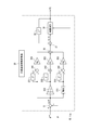
- FIG. 2 is a block diagram showing the overall configuration of the EPS-ECU of one embodiment
- FIG. 3 is a block diagram of the target tracking control calculation unit
- FIG. 4 is a limit calculation map of the follow-up command TC
- FIG. 5A is a block diagram of the intervention detector
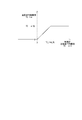
- FIG. 5B is a map of the intervention coefficient ⁇
- FIG. 6 is a block diagram of the limit value calculation unit
- FIG. 7 is a limit calculation map of the follow command limit value TC_lim
- FIG. 8 is a time chart of an operation example by the EPS-ECU of the embodiment.
- the EPS-ECU as a "steering control device” is applied to an electric power steering system of a vehicle and generates "assist control” for generating an assist command for generating an assist torque and a follow-up command for generating an automatic steering torque. Performs "following control”.
- lane keep control is executed to control the steering angle so that the vehicle travels along the lane.
- the electric power steering system 1 is a system that assists a driver's operation of a steering wheel 91 by a driving torque of a motor 80 and executes follow-up control such as lane keeping control.
- a handle 91 is fixed to one end of the steering shaft 92, and an intermediate shaft 93 is provided on the other end of the steering shaft 92.
- the steering shaft 92 and the intermediate shaft 93 are connected by a torsion bar of a torque sensor 94, and these constitute a steering shaft 95.
- the torque sensor 94 detects the steering torque Ts based on the torsion angle of the torsion bar.
- a gear box 96 including a pinion gear 961 and a rack 962 is provided at the end of the intermediate shaft 93 opposite to the torque sensor 94.
- the pinion gear 961 rotates together with the intermediate shaft 93, and the rack 962 moves left and right as the pinion gear 961 rotates.
- Tie rods 97 provided at both ends of the rack 962 are connected to tires 99 via knuckle arms 98. The direction of the tire 99 is changed by the tie rod 97 reciprocating right and left and pulling or pushing the knuckle arm 98.
- the motor 80 is, for example, a three-phase AC brushless motor, and outputs a drive torque according to the drive voltage Vd output from the EPS-ECU 15.
- the drive voltage Vd means each phase voltage of U phase, V phase, and W phase.
- the rotation of the motor 80 is transmitted to the intermediate shaft 93 via a reduction mechanism 85 including a worm gear 86, a worm wheel 87, and the like.
- the steering of the steering wheel 91 and the rotation of the intermediate shaft 93 due to the reaction force from the road surface are transmitted to the motor 80 via the speed reduction mechanism 85.
- the electric power steering system 1 shown in FIG. 1 is a column assist type in which the rotation of the motor 80 is transmitted to the steering shaft 95, but the EPS-ECU 15 of the present embodiment is a rack assist type electric power steering system. Alternatively, it is similarly applicable to a steer-by-wire system in which the steering wheel and the steered wheels are mechanically separated. Further, in other embodiments, a multi-phase AC motor other than three-phase or a brush DC motor may be used as the motor.
- the EPS-ECU 15 controls the steering torque Ts generated by the steering mechanism 100 by controlling the drive torque output from the motor 80 to the steering mechanism 100.
- the EPS-ECU 15 acquires the steering torque Ts, the steering angle ⁇ , and the steering angular velocity ⁇ from the steering system mechanism 100. Further, the EPS-ECU 15 acquires the vehicle speed V detected by the vehicle speed sensor 11 provided in a predetermined part of the vehicle.
- the EPS-ECU 15 acquires the target angle ⁇ * from the LKA (lane keep assist) -ECU 16.
- the LKA-ECU 16 operates by electric power from an in-vehicle battery (not shown), detects a traveling lane and the position of the host vehicle in the traveling lane from an image in front of the vehicle captured by an in-vehicle camera (not shown), and based on the detection result. Set a goal course. Further, the LKA-ECU 16 sets the target angle ⁇ * which is the target value of the motor rotation angle (or steering angle) for traveling along the target course based on the detected values of the vehicle speed and the steering angle, and the EPS. -Output to ECU 15.
- the EPS-ECU 15 operates by electric power from a vehicle-mounted battery (not shown), and generates an assist command and a follow-up command based on the acquired information. Then, the EPS-ECU 15 generates the assist torque and the automatic steering torque by applying the drive voltage Vd to the motor 80 according to the added value of the assist command and the follow-up command. It should be noted that the various arithmetic processes in the EPS-ECU 15 may be software processes by executing a program stored in advance in a substantial memory device such as a ROM by the CPU, or may be hardware processes by a dedicated electronic circuit. It may be.
- the EPS-ECU 15 includes an assist control calculation unit 20, a target tracking control calculation unit 30, an intervention detection unit 40, a limit value calculation unit 50, a command adder 60, a motor drive circuit 65, and the like.
- the configuration other than the limit value calculation unit 50 is basically the same as that of Patent Document 1 (Japanese Patent Laid-Open No. 2015-33942).
- the assist control calculation unit 20 generates an assist command AC that generates an assist torque according to the steering torque Ts.
- the assist control computing unit 20 realizes a feeling of transmission according to a road surface reaction force (or road surface load) and a feel according to a steering state based on the steering torque Ts, the motor rotation angular velocity ⁇ , and the vehicle speed V.
- An assist command AC for generating an assist torque is generated.
- This control executed by the assist control calculator 20 is referred to as "assist control".
- a well-known technique is appropriately used as a specific method of calculating the assist command AC.
- the assist command AC generated by the assist control calculator 20 is output to the command adder 60 and the limit value calculator 50. Further, assist command limit value AC_lim, which is the upper limit of absolute value
- the assist torque and the sign of the assist command AC corresponding to the assist torque are defined according to the rotational direction in which the torque is applied. For example, the torque applied in the left rotation direction is defined as positive, and the torque applied in the right rotation direction is defined as negative.
- the target tracking control calculation unit 30 automatically makes the actual angle ⁇ follow the target angle ⁇ * based on the target angle ⁇ * commanded from the LKA-ECU 16 and the motor rotation angle (hereinafter also referred to as “real angle”) ⁇ .
- a follow-up command TC for generating steering torque is generated.
- the sign of the follow-up command TC is defined similarly to the assist command AC.
- the left side angle with respect to the neutral position is defined as positive and the right side angle with respect to the neutral position is defined as negative.
- the target angle ⁇ * corresponds to the “target value of the physical quantity related to steering”
- the actual angle ⁇ corresponds to the “detected value of the physical quantity”.
- This control executed by the target follow-up control calculator 30 is called “follow-up control”.
- the lane keep control is an example of follow-up control when the physical quantity is a motor rotation angle. Another example of the follow-up control is described in the section of "Other Embodiments".
- the tracking command TC generated by the target tracking control calculation unit 30 is output to the command adder 60, and the added value with the assist command AC is calculated.
- the detailed configuration of the target tracking control calculation unit 30 will be described later with reference to FIGS. 3 and 4.
- the intervention detection unit 40 detects an intervention in the follow-up control by the steering of the driver.
- the intervention detection unit 40 of the present embodiment acquires the steering torque Ts detected by the torque sensor, calculates the intervention coefficient ⁇ based on the absolute value of the steering torque
- the intervention coefficient ⁇ is set to 1 when there is no intervention by the driver's steering, and is set to approach 0 as the degree of intervention increases.
- the detailed configuration of the intervention detection unit 40 will be described later with reference to FIG. 5A.
- the limit value calculation unit 50 acquires the assist command AC and the assist command limit value AC_lim from the assist control calculation unit 20, and acquires the intervention coefficient ⁇ from the intervention detection unit 40.
- the limit value calculation unit 50 calculates the follow-up command limit value TC_lim, which is the upper limit of the absolute value
- the detailed configuration of the limit value calculation unit 50 will be described later with reference to FIGS. 6 and 7.
- the command adder 60 calculates a drive command DC that is an added value of the assist command AC and the follow-up command TC.
- the motor drive circuit 65 drives the motor 80 by applying the drive voltage Vd to the motor 80 according to the drive command DC. As a result, the motor 80 outputs the assist torque and the automatic steering torque corresponding to the drive command DC.
- the present embodiment aims to reduce the steering torque at the time of switching from the follow-up control by the driver's steering to the assist control. Therefore, the limit value calculation unit 50 decreases the follow-up command limit value TC_lim according to the assist command AC.
- the limit value calculation unit 50 decreases the follow-up command limit value TC_lim according to the assist command AC.
- the target follow-up control calculator 30 calculates the follow-up command TC based on the target angle ⁇ * , the actual angle ⁇ , and the follow-up command limit value TC_lim.
- the angle deviation calculator 31 calculates an angle deviation ⁇ between the target angle ⁇ * commanded by the LKA-ECU 16 and the actual angle ⁇ fed back from the controlled object 100.
- PID control is performed so that the angle deviation ⁇ approaches 0.
- the proportional term proportional to the angular deviation ⁇ is calculated by the delay element 331, the subtractor 341 and the Kp multiplier 351.
- the integral term related to the integral value of the angular deviation ⁇ is calculated by the integral calculator 322, the delay element 332, the adder 342, and the Ki multiplier 352.
- T of the integration calculator 322 indicates a calculation cycle, and “s” indicates a variable of bilinear transformation.
- the differential term related to the differential value of the angular deviation ⁇ is calculated by the pseudo differential calculator 323, the delay element 333, the subtractor 343, and the Kd multiplier 353.
- the proportional term, integral term and derivative term are added by the adder 36.
- the previous value of the follow-up command TC input via the delay element 39 is further added to this added value by the adder 37 to calculate the pre-limit follow-up command TC_0.
- the pre-limit follow-up command TC_0 and the follow-up command limit value TC_lim calculated by the limit value calculator 50 are input to the limit calculator 38.
- the pre-limit follow-up command TC_0 takes 0 or a positive or negative value
- the follow-up command limit value TC_lim takes 0 or a positive value.
- the limit calculator 38 compares the absolute value
- the follow-up command TC has its upper limit guarded by the follow-up command limit value TC_lim.
- the pre-limit follow-up command TC_0 is negative, the lower limit of the follow-up command TC is guarded by a negative limit value (-TC_lim) obtained by inverting the follow-up command limit value.
- the intervention detection unit 40 calculates the intervention coefficient ⁇ based on the steering torque Ts.
- the absolute value calculation unit 41 calculates the absolute value
- the map calculator 42 calculates the intervention coefficient ⁇ using the map shown in FIG. 5B.
- This map is similar to that disclosed in FIG. 3 of Patent Document 1. That is, in case of
- ⁇ A, ⁇ 1, in case of
- > B, ⁇ 0, and in the range of A ⁇
- the intervention detection unit 40 may calculate the intervention coefficient ⁇ using a mathematical formula instead of the map.
- the filter processing unit 43 removes noise such as road disturbances superposed on the steering torque Ts by processing the input with a low-pass filter.
- the order of the map calculation unit 42 and the filter processing unit 43 may be exchanged, and the filter processing may be performed before the map calculation.
- the limit value calculation unit 50 calculates the follow-up command limit value TC_lim based on the assist command limit value AC_lim, the intervention coefficient ⁇ , and the assist command AC.
- the assist command limit value AC_lim takes 0 or a positive value
- the assist command AC takes 0 or a positive or negative value.
- the intervention coefficient ⁇ takes a value from 0 to 1.
- the absolute value calculation unit 51 calculates the absolute value
- the filter processing unit 52 removes noise superimposed on the assist command AC by processing the input with a low-pass filter.
- the adjustment gain multiplier 53 multiplies the absolute value
- the subtractor 54 outputs a value obtained by subtracting the output value of the adjustment gain multiplier 53 from the assist command limit value AC_lim as the pre-limit follow-up command limit value TC_lim_0.
- the pre-limit follow-up command limit value TC_lim_0 is reduced by this subtraction. Then, the reduction amount of the pre-limit follow-up command limit value TC_lim_0 due to this subtraction is adjusted by the adjustment gain Kc.
- the pre-limit follow-up command limit value TC_lim_0 is input to the limit calculator 56. Further, the follow-up command limit value upper limit TC_lim_UL calculated by multiplying the assist command limit value AC_lim by the intervention coefficient ⁇ in the multiplier 55 is input to the limit calculation unit 56. The limit calculator 56 compares the pre-limit follow-up command limit value TC_lim_0 with the follow-up command limit value upper limit TC_lim_UL to calculate the follow-up command limit value TC_lim. The calculated tracking command limit value TC_lim is output to the target tracking control calculation unit 30 as described above.
- the limit calculation unit 56 calculates the follow-up command limit value TC_lim by the formula (2.2).
- TC_lim TC_lim_0 (2.2)
- the limit calculator 56 calculates the follow-up command limit value TC_lim by the equation (2.3).
- TC_lim TC_lim_UL (2.3)
- the lower limit of the follow-up command limit value TC_lim is guarded by 0, and the upper limit of the follow-up command limit value TC_lim is guarded by the follow-up command limit value upper limit TC_lim_UL.
- the decrease amount of the pre-limit follow-up command limit value TC_lim_0 due to the subtraction of the subtractor 54 is directly reflected as the decrease amount of the follow-up command limit value TC_lim.
- the entire limit value calculation unit 50 can be understood as “subtraction for reducing the pre-limit follow-up command limit value TC_lim_0” as “subtraction for reducing the follow-up command limit value TC_lim”.
- the solid line in each figure shows the operation of this embodiment in which the follow-up command limit value TC_lim is subtracted, and the alternate long and short dash line shows the operation of the comparative example in which the follow-up command limit value TC_lim is not subtracted.
- the broken line shows the follow-up command limit value TC_lim in the present embodiment
- the two-dot chain line shows the follow-up command limit value TC_lim in the comparative example.
- the follow-up command limit value TC_lim is set to 0 or a positive value and does not become a negative value.
- the follow-up command limit value TC_lim is inverted and shown as a negative value.
- the symbols such as (* 1) in each figure indicate the places quoted in the following description.
- the intervention coefficient ⁇ is set to start decreasing from 1 when the steering torque Ts increases from 0 and exceeds the predetermined threshold for a predetermined time. This prevents erroneous determination that the driver has steered when the steering torque Ts temporarily increases due to disturbance or the like. Specifically, while the steering torque Ts starts to increase at about 0.3 [sec], the intervention coefficient ⁇ starts to decrease from about 0.5 [sec]. When the intervention coefficient ⁇ reaches 0 at about 0.9 [sec], the transition to the assist control is completed.
- the difference in operation between this embodiment and the comparative example finally appears as a difference in steering torque Ts. That is, while the steering torque Ts becomes excessive during control switching in the comparative example, the steering torque Ts is prevented from becoming excessive in the present embodiment, and control switching is smoothly performed.
- the difference in operation will be described in detail.
- (* 1) and (* 2) are the same as in the comparative example.
- the follow-up command limit value TC_lim decreases as the assist command AC increases.
- the follow-up command TC is limited, so that the drive command DC that is the sum of the assist command AC and the follow-up command TC can be output at (* 4p).
- the steering assist by the motor 80 functions, and the steering torque Ts is reduced at (* 5p).
- the limit value calculation unit 50 reduces the follow-up command limit value TC_lim according to the assist command AC when the control is switched from the follow-up control by steering of the driver to the assist control. Specifically, when the absolute value
- the follow-up command TC is prevented from obstructing the steering at the time of control switching from the start of the intervention operation by the steering of the driver to the completion of the transition to the assist control. Therefore, the steering torque Ts at the time of switching the control can be reduced.
- the limit value calculation unit 50 adjusts the decrease amount of the follow-up command limit value TC_lim according to the assist command AC by the adjustment gain Kc of the adjustment gain multiplier 53. As a result, the steering feeling of the driver can be adjusted.
- the limit value calculation unit 50 filters the assist command AC by the filter processing unit 52. As a result, the influence of disturbance or noise can be eliminated and the control can be stabilized.
- the intervention detector 40 calculates 1 by the map calculator 42, which is 1 when there is no intervention by the driver's steering and approaches 0 as the degree of intervention increases. Then, the limit value calculation unit 50 calculates the follow-up command limit value upper limit TC_lim_UL based on the assist command limit value AC_lim and the intervention coefficient ⁇ . As a result, the follow-up command limit value TC_lim can be reduced even if the absolute value
- the “physical quantity related to steering” that is the target of the follow-up control may be an amount such as a steering wheel rotation angle, a tire steering angle, a yaw rate, etc., in addition to the motor rotation angle of the above embodiment.
- “Difference between target value and detected value of physical quantity” means lateral displacement from a target position obtained by a camera, laser radar, millimeter wave radar, etc., deviation from a target locus obtained by GPS, etc., curvature obtained by a road shape. And the like, and in the follow-up control, the automatic steering torque is generated based on these deviations.
- the steering angle follow-up control such as the motor rotation angle can be applied not only to the lane keeping control but also to control such as automatic driving and automatic parking.
- the method of detecting the intervention operation of the driver by the intervention detection unit 40 is not limited to the method based on the steering torque Ts detected by the torque sensor, and, for example, a rotation angle sensor attached to the steering wheel 91 and a motor rotation angle may be used. A method of detecting based on the difference or the changing speed thereof may be used.
- the specific configuration for reducing the follow-up command limit value TC_lim by the limit value calculation unit 50 is not limited to the configuration shown in FIG.
- the pre-limit follow-up command limit value TC_lim_0 may be multiplied by the gain instead of adjusting the reduction amount using the adjustment gain for the assist command AC. If the noise of the assist command AC does not cause a problem, the filtering process may be omitted.
- the follow-up command limit value upper limit TC_lim_UL may be calculated using a coefficient other than the intervention coefficient ⁇ .
- the follow-up command limit value TC_lim is set to take 0 or a positive value, but the follow-up command limit value TC_lim may be set to 0 or a positive or negative value. Even if the follow-up command limit value TC_lim takes a negative value in that configuration, the limit value calculation unit 50 “decreases the absolute value
- control unit and the method described in the present disclosure are realized by a dedicated computer provided by configuring a processor and a memory programmed to execute one or a plurality of functions embodied by a computer program. May be done.
- control unit and the method described in the present disclosure may be realized by a dedicated computer provided by configuring a processor with one or more dedicated hardware logic circuits.
- control unit and the method thereof described in the present disclosure are based on a combination of a processor and a memory programmed to execute one or more functions and a processor configured by one or more hardware logic circuits. It may be implemented by one or more dedicated computers configured.
- the computer program may be stored in a computer-readable non-transition tangible recording medium as an instruction executed by a computer.
Landscapes
- Engineering & Computer Science (AREA)
- Chemical & Material Sciences (AREA)
- Combustion & Propulsion (AREA)
- Transportation (AREA)
- Mechanical Engineering (AREA)
- Steering Control In Accordance With Driving Conditions (AREA)
- Power Steering Mechanism (AREA)
Abstract
アシスト制御演算部(20)は、アシストトルクを発生させるアシスト指令(AC)を生成する制御である「アシスト制御」を実行する。目標追従制御演算部(30)は、自動操舵トルクを発生させる追従指令(TC)を生成する制御である「追従制御」を実行する。介入検出部(40)は、ドライバの操舵による追従制御への介入を検出する。制限値演算部(50)は、追従指令制限値(TC_lim)を演算し、目標追従制御演算部(30)に出力する。モータ駆動回路(65)は、アシスト指令(AC)と追従指令(TC)との加算値である駆動指令(DC)に従ってモータ(80)を駆動する。制限値演算部(50)は、ドライバの操舵による追従制御からアシスト制御への制御切り替え時に、アシスト指令(AC)に応じて追従指令制限値(TC_lim)の絶対値を減少させる。
Description
本出願は、2018年11月2日に出願された特許出願番号2018-207499号に基づくものであり、ここにその記載内容を援用する。
本開示は、ステアリング制御装置に関する。
従来、アシストトルクを発生させるアシスト制御、及び、自動操舵トルクを発生させるレーンキープ制御等の追従制御を実行するステアリング制御装置において、追従制御中にドライバによる介入動作が行われたとき、制御を切り替える技術が知られている。例えば特許文献1に開示された制御装置は、アシスト指令を生成するアシスト制御演算部と、モータの実角度を目標角度に追従させるように追従指令を生成する目標追従制御演算部と、ドライバによる追従制御への介入を検出する介入検出部と、を備える。介入検出部は、ドライバの操舵介入度合いが大きいほど、値が1から0に小さくなる介入係数を生成する。目標追従制御演算部は、介入係数が1から0に近づくほど、追従制御の応答性を低下させる。
特許文献1の技術において、ドライバの操舵による介入動作が開始されてから、介入係数が0に下がりアシスト制御への移行が完了するまでの制御切り替え中には、追従指令による自動操舵トルクが依然として生成される。この自動操舵トルクによりアシストトルクが打ち消されるため、制御切り替え中の操舵トルクが過大になるおそれがある。
本開示の目的は、ドライバの操舵による追従制御からアシスト制御への切り替え時における操舵トルクを低減するステアリング制御装置を提供することにある。
本開示のステアリング制御装置は、アシスト制御演算部と、目標追従制御演算部と、介入検出部と、制限値演算部と、モータ駆動回路と、を備える。
アシスト制御演算部は、「操舵トルクに応じたアシストトルクを発生させるアシスト指令を生成する制御」である「アシスト制御」を実行する。目標追従制御演算部は、「操舵に関わる物理量の目標値を取得し該目標値に前記物理量の検出値を追従させる自動操舵トルクを発生させる追従指令を生成する制御」である「追従制御」を実行する。
介入検出部は、ドライバの操舵による追従制御への介入を検出する。制限値演算部は、追従指令の絶対値の上限である「追従指令制限値」を演算し、目標追従制御演算部に出力する。モータ駆動回路は、アシストトルク及び自動操舵トルクを出力するモータを、アシスト指令と追従指令との加算値である駆動指令に従って駆動する。
制限値演算部は、ドライバの操舵による追従制御からアシスト制御への制御切り替え時に、アシスト指令に応じて追従指令制限値の絶対値を減少させる。具体的に制限値演算部は、アシスト指令の絶対値が0の場合、追従指令制限値の絶対値をそのまま維持し、アシスト指令の絶対値が大きいほど、追従指令制限値の絶対値を減少させる。
これにより本開示では、ドライバの操舵による介入動作が開始されてからアシスト制御への移行が完了するまでの制御切り替え時に、追従指令が操舵を阻害することが抑制される。したがって、制御切り替え時における操舵トルクを低減することができる。
本開示についての上記目的及びその他の目的、特徴や利点は、添付の図面を参照しながら下記の詳細な記述により、より明確になる。その図面は、
図1は、電動パワーステアリングシステムの概略構成図であり、
図2は、一実施形態のEPS-ECUの全体構成を示すブロック図であり、
図3は、目標追従制御演算部のブロック図であり、
図4は、追従指令TCの制限演算マップであり、
図5Aは、介入検出部のブロック図であり、
図5Bは、介入係数αのマップであり、
図6は、制限値演算部のブロック図であり、
図7は、追従指令制限値TC_limの制限演算マップであり、
図8は、一実施形態のEPS-ECUによる動作例のタイムチャートである。
以下、ステアリング制御装置の一実施形態を図面に基づいて説明する。「ステアリング制御装置」としてのEPS-ECUは、車両の電動パワーステアリングシステムに適用され、アシストトルクを発生させるアシスト指令を生成する「アシスト制御」、及び、自動操舵トルクを発生させる追従指令を生成する「追従制御」を行う。本実施形態では、追従制御として、車両がレーンに沿って走行するように舵角を制御するレーンキープ制御を実行する。
[電動パワーステアリングシステムの構成]
図1に示すように、電動パワーステアリングシステム1は、モータ80の駆動トルクにより、ドライバによるハンドル91の操作をアシストするとともにレーンキープ制御等の追従制御を実行するシステムである。ステアリングシャフト92の一端にはハンドル91が固定されており、ステアリングシャフト92の他端側にはインターミディエイトシャフト93が設けられている。ステアリングシャフト92とインターミディエイトシャフト93とは、トルクセンサ94のトーションバーにより接続されており、これらにより操舵軸95が構成される。トルクセンサ94は、トーションバーの捩れ角に基づいて操舵トルクTsを検出する。
図1に示すように、電動パワーステアリングシステム1は、モータ80の駆動トルクにより、ドライバによるハンドル91の操作をアシストするとともにレーンキープ制御等の追従制御を実行するシステムである。ステアリングシャフト92の一端にはハンドル91が固定されており、ステアリングシャフト92の他端側にはインターミディエイトシャフト93が設けられている。ステアリングシャフト92とインターミディエイトシャフト93とは、トルクセンサ94のトーションバーにより接続されており、これらにより操舵軸95が構成される。トルクセンサ94は、トーションバーの捩れ角に基づいて操舵トルクTsを検出する。
インターミディエイトシャフト93のトルクセンサ94と反対側の端部には、ピニオンギア961及びラック962を含むギアボックス96が設けられている。ドライバがハンドル91を回すと、インターミディエイトシャフト93とともにピニオンギア961が回転し、ピニオンギア961の回転に伴って、ラック962が左右に移動する。ラック962の両端に設けられたタイロッド97は、ナックルアーム98を介してタイヤ99と接続されている。タイロッド97が左右に往復運動し、ナックルアーム98を引っ張ったり押したりすることで、タイヤ99の向きが変わる。
モータ80は、例えば3相交流ブラシレスモータであり、EPS-ECU15から出力された駆動電圧Vdに応じて、駆動トルクを出力する。3相交流モータの場合、駆動電圧Vdは、U相、V相、W相の各相電圧を意味する。モータ80の回転は、ウォームギア86及びウォームホイール87等により構成される減速機構85を経由して、インターミディエイトシャフト93に伝達される。また、ハンドル91の操舵や、路面からの反力によるインターミディエイトシャフト93の回転は、減速機構85を経由してモータ80に伝達される。
なお、図1に示す電動パワーステアリングシステム1は、モータ80の回転が操舵軸95に伝達されるコラムアシスト式であるが、本実施形態のEPS-ECU15は、ラックアシスト式の電動パワーステアリングシステム、或いは、ハンドルと操舵輪とが機械的に切り離されたステアバイワイヤシステムにも同様に適用可能である。また、他の実施形態では、モータとして、3相以外の多相交流モータや、ブラシ付DCモータが用いられてもよい。
ここで、ハンドル91からタイヤ99に至る、ハンドル91の操舵力が伝達される機構全体を「操舵系メカ100」という。EPS-ECU15は、モータ80が操舵系メカ100に出力する駆動トルクを制御することにより、操舵系メカ100が発生する操舵トルクTsを制御する。EPS-ECU15は、操舵系メカ100から操舵トルクTs、操舵角θ及び操舵角速度ωを取得する。また、EPS-ECU15は、車両の所定の部位に設けられた車速センサ11が検出した車速Vを取得する。
さらにEPS-ECU15は、LKA(レーンキープアシスト)-ECU16から目標角度θ*を取得する。LKA-ECU16は、図示しない車載バッテリからの電力によって動作し、図示しない車載カメラによって撮像された車両前方の画像から、走行レーンや走行レーンにおける自車両の位置を検出し、その検出結果に基づいて目標コースを設定する。さらに、LKA-ECU16は、車速や舵角の検出値等に基づいて、目標コースに沿って走行するためのモータ回転角(或いは操舵角)の目標値である目標角度θ*を設定し、EPS-ECU15に出力する。
EPS-ECU15は、図示しない車載バッテリからの電力によって動作し、取得した情報に基づいて、アシスト指令及び追従指令を生成する。そしてEPS-ECU15は、アシスト指令と追従指令との加算値に従って駆動電圧Vdをモータ80へ印加することにより、アシストトルク及び自動操舵トルクを発生させる。なお、EPS-ECU15における各種演算処理は、ROM等の実体的なメモリ装置に予め記憶されたプログラムをCPUで実行することによるソフトウェア処理であってもよいし、専用の電子回路によるハードウェア処理であってもよい。
[EPS-ECUの構成及び作用効果]
次にEPS-ECU15の具体的な構成及び作用効果について説明する。図2に示すように、EPS-ECU15は、アシスト制御演算部20、目標追従制御演算部30、介入検出部40、制限値演算部50、指令加算器60及びモータ駆動回路65等を備える。制限値演算部50以外の構成は、基本的に特許文献1(特開2015-33942号公報)と同様である。
次にEPS-ECU15の具体的な構成及び作用効果について説明する。図2に示すように、EPS-ECU15は、アシスト制御演算部20、目標追従制御演算部30、介入検出部40、制限値演算部50、指令加算器60及びモータ駆動回路65等を備える。制限値演算部50以外の構成は、基本的に特許文献1(特開2015-33942号公報)と同様である。
アシスト制御演算部20は、操舵トルクTsに応じたアシストトルクを発生させるアシスト指令ACを生成する。詳しくは、アシスト制御演算部20は、操舵トルクTs、モータ回転角速度ω、車速Vに基づき、路面反力(或いは路面負荷)に応じた伝達感や、操舵状態に応じたフィールが実現されるようにアシストトルクを発生させるアシスト指令ACを生成する。アシスト制御演算部20が実行するこの制御を「アシスト制御」という。アシスト指令ACの具体的な算出方法としては、周知の技術が適宜用いられる。
アシスト制御演算部20が生成したアシスト指令ACは指令加算器60に出力されると共に制限値演算部50に出力される。また、アシスト指令の絶対値|AC|の上限であるアシスト指令制限値AC_limがアシスト制御演算部20から制限値演算部50に出力される。なお、アシストトルクや、それに対応するアシスト指令ACの符号は、トルクが印加される回転方向に応じて定義される。例えば左回転方向に印加されるトルクが正、右回転方向に印加されるトルクが負と定義される。
目標追従制御演算部30は、LKA-ECU16から指令される目標角度θ*、及び、モータ回転角(以下「実角度」ともいう)θに基づき、実角度θを目標角度θ*に追従させる自動操舵トルクを発生させる追従指令TCを生成する。追従指令TCの符号は、アシスト指令ACと同様に定義される。また、目標角度θ*及び実角度θについては、例えば中立位置に対し左側の角度が正、中立位置に対し右側の角度が負と定義される。
ここで、目標角度θ*は「操舵に関わる物理量の目標値」に相当し、実角度θは「物理量の検出値」に相当する。目標追従制御演算部30が実行するこの制御を「追従制御」という。レーンキープ制御は、物理量がモータ回転角である場合の追従制御の一例である。他の追従制御の例は、「その他の実施形態」の欄に記載する。
目標追従制御演算部30が生成した追従指令TCは指令加算器60に出力され、アシスト指令ACとの加算値が算出される。目標追従制御演算部30の詳細な構成は、図3、図4を参照して後述する。
介入検出部40は、ドライバの操舵による追従制御への介入を検出する。本実施形態の介入検出部40は、トルクセンサにより検出された操舵トルクTsを取得し、操舵トルクの絶対値|Ts|に基づき介入係数αを算出して制限値演算部50に出力する。介入係数αは、ドライバの操舵による介入が無いとき1であり、介入の程度が大きいほど0に近づくように設定されている。介入検出部40の詳細な構成は、図5Aを参照して後述する。
制限値演算部50は、アシスト制御演算部20からアシスト指令AC及びアシスト指令制限値AC_limを取得し、介入検出部40から介入係数αを取得する。制限値演算部50は、これらの情報に基づいて追従指令の絶対値|TC|の上限である追従指令制限値TC_limを演算し、目標追従制御演算部30に出力する。特にドライバの操舵による追従制御からアシスト制御への制御切り替え時に、制限値演算部50はアシスト指令ACに応じて追従指令制限値TC_limを減少させる。制限値演算部50の詳細な構成は、図6、図7を参照して後述する。
指令加算器60は、アシスト指令ACと追従指令TCとの加算値である駆動指令DCを算出する。モータ駆動回路65は、駆動指令DCに従ってモータ80へ駆動電圧Vdを印加することでモータ80を駆動する。これによりモータ80は、駆動指令DCに対応したアシストトルク及び自動操舵トルクを出力する。
ところで特許文献1の従来技術では、追従制御の実行中にドライバの操舵による介入を介入検出部40が検出したとき、追従制御の応答性を低下させ、アシスト制御の実行度合を増加させる。ただし、ドライバの操舵による介入動作が開始されてから、介入係数が0に下がりアシスト制御への移行が完了するまでの制御切り替え中には、追従指令による自動操舵トルクが依然として生成される。この自動操舵トルクによりアシストトルクが打ち消されるため、制御切り替え中の操舵トルクが過大になるおそれがある。
そこで本実施形態では、ドライバの操舵による追従制御からアシスト制御への切り替え時における操舵トルクを低減することを目的とする。そのために、制限値演算部50は、アシスト指令ACに応じて追従指令制限値TC_limを減少させる。以下、これに関する構成を中心として詳しく説明する。
図3、図4を参照し、目標追従制御演算部30の構成について説明する。図3に示すように、目標追従制御演算部30は、目標角度θ*、実角度θ、及び追従指令制限値TC_limに基づいて追従指令TCを演算する。角度偏差算出器31は、LKA-ECU16から指令される目標角度θ*と、制御対象100からフィードバックされる実角度θとの角度偏差Δθを算出する。
本実施形態では、角度偏差Δθを0に近づけるようにPID制御が行われる。角度偏差Δθに比例する比例項は、遅延素子331、減算器341及びKp乗算器351により演算される。角度偏差Δθの積分値に関する積分項は、積分演算器322、遅延素子332、加算器342及びKi乗算器352により演算される。積分演算器322の「T」は演算周期を示し、「s」は双一次変換の変数を示す。角度偏差Δθの微分値に関する微分項は、擬似微分演算器323、遅延素子333、減算器343及びKd乗算器353により演算される。
比例項、積分項及び微分項は加算器36で加算される。この加算値に、遅延素子39を介して入力される追従指令TCの前回値が加算器37でさらに加算されて制限前追従指令TC_0が演算される。
制限前追従指令TC_0、及び、制限値演算部50が演算した追従指令制限値TC_limは制限演算部38に入力される。ここで、制限前追従指令TC_0は0又は正負の値を取り、追従指令制限値TC_limは0又は正の値を取る。制限演算部38は、制限前追従指令の絶対値|TC_0|を追従指令制限値TC_limと比較して追従指令TCを演算する。
「|TC_0|≦TC_lim」のとき、制限演算部38は、式(1.1)により追従指令TCを演算する。
TC=TC_0 ・・・(1.1)
TC=TC_0 ・・・(1.1)
「TC_lim<|TC_0|」のとき、制限演算部38は、式(1.2)により追従指令TCを演算する。
TC=TC_lim×sgn(TC_0) ・・・(1.2)
TC=TC_lim×sgn(TC_0) ・・・(1.2)
すなわち、図4に示すように、制限前追従指令TC_0が正のとき、追従指令TCは、追従指令制限値TC_limにより上限がガードされる。制限前追従指令TC_0が負のとき、追従指令TCは、追従指令制限値を正負反転した負の制限値(-TC_lim)により下限がガードされる。
次に図5A、図5Bを参照し、介入検出部40の構成について説明する。図5Aに示すように、介入検出部40は操舵トルクTsに基づいて介入係数αを算出する。絶対値演算部41は、操舵トルクの絶対値|Ts|を演算する。マップ演算部42は、図5Bに示すマップを用いて介入係数αを算出する。このマップは、特許文献1の図3に開示されたものと同様である。すなわち、|Ts|<Aではα=1であり、|Ts|>Bではα=0であり、A≦|Ts|≦Bの範囲では、|Ts|の増加に伴って、αは1から0に単調減少する。なお、介入検出部40は、マップに代えて数式により介入係数αを算出してもよい。
フィルタ処理部43は、入力をローパスフィルタで処理することで、操舵トルクTsに重畳された路面外乱等のノイズを除去する。なお、マップ演算部42とフィルタ処理部43との順番を入れ替え、マップ演算より先にフィルタ処理を行ってもよい。
次に図6、図7を参照し、制限値演算部50の構成について説明する。図6に示すように、制限値演算部50は、アシスト指令制限値AC_lim、介入係数α及びアシスト指令ACに基づいて追従指令制限値TC_limを演算する。ここで、アシスト指令制限値AC_limは0又は正の値を取り、アシスト指令ACは0又は正負の値を取る。また、介入係数αは0から1までの値を取る。
絶対値演算部51は、アシスト指令の絶対値|AC|を演算する。フィルタ処理部52は、入力をローパスフィルタで処理することで、アシスト指令ACに重畳されたノイズを除去する。調整ゲイン乗算器53は、フィルタ処理後のアシスト指令の絶対値|AC|に正の値である調整ゲインKcを乗算する。この乗算結果、すなわち調整ゲイン乗算器53の出力値は0又は正の値となる。
減算器54は、アシスト指令制限値AC_limから調整ゲイン乗算器53の出力値を減算した値を制限前追従指令制限値TC_lim_0として出力する。アシスト指令ACが0の場合を実質的に除外すると、この減算により、制限前追従指令制限値TC_lim_0は減少する。そして、この減算による制限前追従指令制限値TC_lim_0の減少量が調整ゲインKcによって調整される。
制限前追従指令制限値TC_lim_0は制限演算部56に入力される。また、乗算器55でアシスト指令制限値AC_limに介入係数αを乗じて算出された追従指令制限値上限TC_lim_ULが制限演算部56に入力される。制限演算部56は、制限前追従指令制限値TC_lim_0を追従指令制限値上限TC_lim_ULと比較して追従指令制限値TC_limを演算する。演算された追従指令制限値TC_limは、上述の通り、目標追従制御演算部30に出力される。
「TC_lim_0<0」のとき、制限演算部56は、式(2.1)により追従指令制限値TC_limを演算する。
TC_lim=0 ・・・(2.1)
TC_lim=0 ・・・(2.1)
「0≦TC_lim_0≦TC_lim_UL」のとき、制限演算部56は、式(2.2)により追従指令制限値TC_limを演算する。
TC_lim=TC_lim_0 ・・・(2.2)
TC_lim=TC_lim_0 ・・・(2.2)
「TC_lim_UL<TC_lim_0」のとき、制限演算部56は、式(2.3)により追従指令制限値TC_limを演算する。
TC_lim=TC_lim_UL ・・・(2.3)
TC_lim=TC_lim_UL ・・・(2.3)
すなわち、図7に示すように、追従指令制限値TC_limの下限は0でガードされ、追従指令制限値TC_limの上限は追従指令制限値上限TC_lim_ULでガードされる。「0≦TC_lim_0≦TC_lim_UL」の範囲では、減算器54の減算による制限前追従指令制限値TC_lim_0の減少量がそのまま追従指令制限値TC_limの減少量として反映される。要するに、制限値演算部50全体として、「制限前追従指令制限値TC_lim_0を減少させる減算」を「追従指令制限値TC_limを減少させる減算」と理解することができる。
次に図8のタイムチャートを参照し、本実施形態による動作例を説明する。この動作例では、目標角度θ*=0[deg]の時、ドライバの操舵によって追従制御からアシスト制御に制御を切り替える。図8の縦軸は、上から順に、実角度θ、操舵トルクTs、介入係数α、アシスト指令AC、追従指令TC、及び、駆動指令DCを示す。
各図中の実線は、追従指令制限値TC_limの減算を行う本実施形態の動作を示し、一点鎖線は、追従指令制限値TC_limの減算をしない比較例の動作を示す。追従指令TCの図において、破線は、本実施形態での追従指令制限値TC_limを示し、二点鎖線は、比較例での追従指令制限値TC_limを示す。なお、本実施形態では追従指令制限値TC_limは0又は正の値に設定され、負の値にはならない。ただし、追従指令TCの図では、対照のための便宜上、追従指令制限値TC_limの正負を反転し、負の値として記す。また、各図の(*1)等の記号は、以下の説明中で引用される箇所を示す。
ここで、本実施形態では、操舵トルクTsが0から増加して所定の閾値を超えた状態が所定時間継続したとき、介入係数αが1から低下し始めるように設定されている。これにより、外乱等によって操舵トルクTsが一時的に増加したとき、ドライバの操舵が行われたと誤判定することが回避される。具体的には約0.3[sec]の時に操舵トルクTsが増加し始めているのに対し、介入係数αは約0.5[sec]から低下し始めている。約0.9[sec]で介入係数αが0に達すると、アシスト制御への移行が完了する。
本実施形態と比較例との動作の違いは、最終的に操舵トルクTsの違いとして現れる。すなわち、比較例では制御切り替え中に操舵トルクTsが過大となるのに対し、本実施形態では操舵トルクTsが過大となることが防止され、制御の切り替えがスムーズに行われる。以下、その動作の違いについて詳しく説明する。
まず、比較例において操舵トルクTsが過大となるまでの流れを説明する。(*1)では、ドライバ操舵によって実角度θが目標角度θ*から乖離する。(*2)では、乖離を修正するため、操舵方向と逆方向(図では負方向)の追従指令TCが出力される。(*3c)において追従指令制限値TC_limは減算されず、一定である。追従指令TCは、0.3[sec]の手前から約0.5[sec]にかけて追従指令制限値TC_limで制限され、その後、介入係数αの低下に伴い、絶対値が減少する。
(*4c)では、ドライバ操舵によって生じるアシスト指令AC(図では正のトルク)が追従指令TC(負のトルク)に打ち消される。そのため、アシスト指令ACと追従指令TCとの和である駆動指令DCが出力されない。駆動指令DCが出力されないため、(*5c)において操舵トルクTsが過大となる。
次に、本実施形態のロジックにより、制御切り替えがスムーズとなる流れを説明する。(*1)、(*2)は比較例と同様である。(*3p)では、アシスト指令ACの増加に応じて追従指令制限値TC_limが減少する。これにより、追従指令TCが制限されるため、(*4p)でアシスト指令ACと追従指令TCとの和である駆動指令DCが出力可能となる。その結果、モータ80による操舵アシストが機能し、(*5p)で操舵トルクTsが低減される。
(効果)
(1)本実施形態のEPS-ECU15において制限値演算部50は、ドライバの操舵による追従制御からアシスト制御への制御切り替え時に、アシスト指令ACに応じて追従指令制限値TC_limを減少させる。具体的に制限値演算部50は、アシスト指令の絶対値|Ac|が0の場合、追従指令制限値TC_limをそのまま維持し、アシスト指令の絶対値|Ac|が大きいほど追従指令制限値TC_limを減少させる。
(1)本実施形態のEPS-ECU15において制限値演算部50は、ドライバの操舵による追従制御からアシスト制御への制御切り替え時に、アシスト指令ACに応じて追従指令制限値TC_limを減少させる。具体的に制限値演算部50は、アシスト指令の絶対値|Ac|が0の場合、追従指令制限値TC_limをそのまま維持し、アシスト指令の絶対値|Ac|が大きいほど追従指令制限値TC_limを減少させる。
これにより本実施形態では、ドライバの操舵による介入動作が開始されてからアシスト制御への移行が完了するまでの制御切り替え時に、追従指令TCが操舵を阻害することが抑制される。したがって、制御切り替え時における操舵トルクTsを低減することができる。
(2)制限値演算部50は、アシスト指令ACに応じた追従指令制限値TC_limの減少量を、調整ゲイン乗算器53の調整ゲインKcによって調整する。これにより、ドライバの操舵感の調整ができる。
(3)制限値演算部50は、フィルタ処理部52によりアシスト指令ACをフィルタ処理する。これにより、外乱やノイズの影響を排除し、制御を安定化することができる。
(4)介入検出部40は、ドライバの操舵による介入が無いとき1であり、介入の程度が大きいほど0に近づく介入係数αをマップ演算部42により算出する。そして、制限値演算部50は、アシスト指令制限値AC_lim及び介入係数αに基づいて追従指令制限値上限TC_lim_ULを演算する。これにより、アシスト指令の絶対値|Ac|が比較的小さくても、追従指令制限値TC_limを低下させることができる。
(その他の実施形態)
(1)追従制御の対象となる「操舵に関わる物理量」は、上記実施形態のモータ回転角の他、ハンドル回転角、タイヤ転舵角、ヨーレート等の量でもよい。「物理量の目標値と検出値との偏差」は、カメラ、レーザレーダ、ミリ波レーダ等によって得られる目標位置との横変位、GPS等によって得られる目標軌跡との偏差、道路形状によって得られる曲率との偏差等でもよく、追従制御では、これらの偏差に基づいて自動操舵トルクを発生させる。また、モータ回転角等の舵角追従制御としては、レーンキープ制御の他に、自動運転、自動駐車等の制御にも適用可能である。
(1)追従制御の対象となる「操舵に関わる物理量」は、上記実施形態のモータ回転角の他、ハンドル回転角、タイヤ転舵角、ヨーレート等の量でもよい。「物理量の目標値と検出値との偏差」は、カメラ、レーザレーダ、ミリ波レーダ等によって得られる目標位置との横変位、GPS等によって得られる目標軌跡との偏差、道路形状によって得られる曲率との偏差等でもよく、追従制御では、これらの偏差に基づいて自動操舵トルクを発生させる。また、モータ回転角等の舵角追従制御としては、レーンキープ制御の他に、自動運転、自動駐車等の制御にも適用可能である。
(2)介入検出部40がドライバの介入操作を検出する方法は、トルクセンサが検出した操舵トルクTsに基づく方法に限らず、例えば、ハンドル91に取り付けられた回転角センサとモータ回転角との差やその変化速度に基づいて検出する方法としてもよい。
(3)制限値演算部50により追従指令制限値TC_limを減少させる具体的な構成は、図6に示す構成に限らない。例えば、アシスト指令ACに対する調整ゲインを用いて減少量を調整するのでなく、制限前追従指令制限値TC_lim_0にゲインを乗じてもよい。また、アシスト指令ACのノイズが問題とならない場合、フィルタ処理を省略してもよい。さらに、介入係数α以外の係数を用いて追従指令制限値上限TC_lim_ULを演算してもよい。
(4)上記実施形態では、追従指令制限値TC_limは0又は正の値を取るものとして設定されているが、追従指令制限値TC_limが0又は正負の値を取るように設定されてもよい。その構成において追従指令制限値TC_limが負の値を取る場合でも、制限値演算部50が「アシスト指令ACに応じて追従指令制限値の絶対値|TC_lim|を減少させる」ことで、上記実施形態と同様のロジックでの制御が可能となる。
以上、本開示は、上記実施形態になんら限定されるものではなく、その趣旨を逸脱しない範囲において種々の形態で実施可能である。
本開示に記載の制御部及びその手法は、コンピュータプログラムにより具体化された一つ乃至は複数の機能を実行するようにプログラムされたプロセッサ及びメモリを構成することによって提供された専用コンピュータにより、実現されてもよい。あるいは、本開示に記載の制御部及びその手法は、一つ以上の専用ハードウェア論理回路によってプロセッサを構成することによって提供された専用コンピュータにより、実現されてもよい。もしくは、本開示に記載の制御部及びその手法は、一つ乃至は複数の機能を実行するようにプログラムされたプロセッサ及びメモリと一つ以上のハードウェア論理回路によって構成されたプロセッサとの組み合わせにより構成された一つ以上の専用コンピュータにより、実現されてもよい。また、コンピュータプログラムは、コンピュータにより実行されるインストラクションとして、コンピュータ読み取り可能な非遷移有形記録媒体に記憶されていてもよい。
本開示は実施形態に準拠して記述された。しかしながら、本開示は当該実施形態および構造に限定されるものではない。本開示は、様々な変形例および均等の範囲内の変形をも包含する。また、様々な組み合わせおよび形態、さらには、それらに一要素のみ、それ以上、あるいはそれ以下、を含む他の組み合わせおよび形態も本開示の範疇および思想範囲に入るものである。
Claims (4)
- 操舵トルク(Ts)に応じたアシストトルクを発生させるアシスト指令(AC)を生成する制御であるアシスト制御を実行するアシスト制御演算部(20)と、
操舵に関わる物理量の目標値を取得し該目標値に前記物理量の検出値を追従させる自動操舵トルクを発生させる追従指令(TC)を生成する制御である追従制御を実行する目標追従制御演算部(30)と、
ドライバの操舵による前記追従制御への介入を検出する介入検出部(40)と、
前記追従指令の絶対値の上限である追従指令制限値を演算し、前記目標追従制御演算部に出力する制限値演算部(50)と、
前記アシストトルク及び前記自動操舵トルクを出力するモータ(80)を、前記アシスト指令と前記追従指令との加算値である駆動指令(DC)に従って駆動するモータ駆動回路(65)と、
を備え、
前記制限値演算部は、ドライバの操舵による前記追従制御から前記アシスト制御への制御切り替え時に、前記アシスト指令に応じて前記追従指令制限値の絶対値を減少させるステアリング制御装置。 - 前記制限値演算部は、前記アシスト指令に応じた前記追従指令制限値の絶対値の減少量を調整ゲインによって調整する請求項1に記載のステアリング制御装置。
- 前記制限値演算部は、前記アシスト指令をフィルタ処理する請求項1または2に記載のステアリング制御装置。
- 前記介入検出部は、ドライバの操舵による介入が無いとき1であり、介入の程度が大きいほど0に近づく介入係数(α)を算出し、
前記制限値演算部は、前記アシスト指令の絶対値の上限であるアシスト指令制限値(AC_lim)及び前記介入係数に基づいて、前記追従指令制限値の絶対値の上限(TC_lim_UL)を演算する請求項1~3のいずれか一項に記載のステアリング制御装置。
Priority Applications (2)
| Application Number | Priority Date | Filing Date | Title |
|---|---|---|---|
| CN201980071491.XA CN113039117B (zh) | 2018-11-02 | 2019-10-17 | 转向控制装置 |
| US17/242,602 US12024241B2 (en) | 2018-11-02 | 2021-04-28 | Steering control device |
Applications Claiming Priority (2)
| Application Number | Priority Date | Filing Date | Title |
|---|---|---|---|
| JP2018-207499 | 2018-11-02 | ||
| JP2018207499A JP7056518B2 (ja) | 2018-11-02 | 2018-11-02 | ステアリング制御装置 |
Related Child Applications (1)
| Application Number | Title | Priority Date | Filing Date |
|---|---|---|---|
| US17/242,602 Continuation US12024241B2 (en) | 2018-11-02 | 2021-04-28 | Steering control device |
Publications (1)
| Publication Number | Publication Date |
|---|---|
| WO2020090493A1 true WO2020090493A1 (ja) | 2020-05-07 |
Family
ID=70463088
Family Applications (1)
| Application Number | Title | Priority Date | Filing Date |
|---|---|---|---|
| PCT/JP2019/040850 WO2020090493A1 (ja) | 2018-11-02 | 2019-10-17 | ステアリング制御装置 |
Country Status (4)
| Country | Link |
|---|---|
| US (1) | US12024241B2 (ja) |
| JP (1) | JP7056518B2 (ja) |
| CN (1) | CN113039117B (ja) |
| WO (1) | WO2020090493A1 (ja) |
Cited By (2)
| Publication number | Priority date | Publication date | Assignee | Title |
|---|---|---|---|---|
| WO2021161676A1 (ja) * | 2020-02-14 | 2021-08-19 | 株式会社デンソー | 操舵制御装置、操舵制御方法、および操舵制御プログラム |
| CN114506318A (zh) * | 2020-10-29 | 2022-05-17 | 本田技研工业株式会社 | 车辆控制装置、车辆控制方法以及记录介质 |
Families Citing this family (5)
| Publication number | Priority date | Publication date | Assignee | Title |
|---|---|---|---|---|
| KR20210085611A (ko) * | 2019-12-31 | 2021-07-08 | 현대모비스 주식회사 | 전동식 조향장치의 제어장치 및 그 방법 |
| JP7433410B2 (ja) * | 2020-02-27 | 2024-02-19 | 三菱電機株式会社 | 操舵制御装置 |
| CN113753122B (zh) * | 2020-06-05 | 2022-11-01 | 广州汽车集团股份有限公司 | 电动助力转向控制方法、电动助力转向系统及存储介质 |
| JP7261782B2 (ja) | 2020-10-29 | 2023-04-20 | 本田技研工業株式会社 | 車両制御装置、車両制御方法、およびプログラム |
| DE102021202482B4 (de) * | 2021-03-15 | 2023-06-29 | Continental Automotive Technologies GmbH | Regelungseinrichtung und Verfahren zur Lenkwinkelregelung eines Fahrzeugs |
Citations (6)
| Publication number | Priority date | Publication date | Assignee | Title |
|---|---|---|---|---|
| WO2014162769A1 (ja) * | 2013-04-04 | 2014-10-09 | 日本精工株式会社 | 電動パワーステアリング装置 |
| JP2015020604A (ja) * | 2013-07-19 | 2015-02-02 | 株式会社デンソー | モータ制御装置 |
| US20170217477A1 (en) * | 2016-01-28 | 2017-08-03 | Denso Corporation | Motor controller |
| JP2018008649A (ja) * | 2016-07-15 | 2018-01-18 | 株式会社デンソー | 車両の運転支援装置 |
| JP2018024281A (ja) * | 2016-08-08 | 2018-02-15 | 株式会社ジェイテクト | アクチュエータ制御装置 |
| WO2018056077A1 (ja) * | 2016-09-23 | 2018-03-29 | Kyb株式会社 | 電動パワーステアリング装置 |
Family Cites Families (5)
| Publication number | Priority date | Publication date | Assignee | Title |
|---|---|---|---|---|
| JP6213033B2 (ja) * | 2013-08-09 | 2017-10-18 | 株式会社デンソー | モータ制御装置 |
| US9586619B1 (en) * | 2016-02-12 | 2017-03-07 | Denso Corporation | Motor controller |
| EP3453592B1 (en) * | 2016-06-06 | 2020-02-26 | NSK Ltd. | Electric power steering device |
| JP6528786B2 (ja) * | 2017-01-13 | 2019-06-12 | トヨタ自動車株式会社 | 車両の運転支援装置 |
| US10996673B1 (en) * | 2017-09-28 | 2021-05-04 | Apple Inc. | Manual override |
-
2018
- 2018-11-02 JP JP2018207499A patent/JP7056518B2/ja active Active
-
2019
- 2019-10-17 CN CN201980071491.XA patent/CN113039117B/zh active Active
- 2019-10-17 WO PCT/JP2019/040850 patent/WO2020090493A1/ja active Application Filing
-
2021
- 2021-04-28 US US17/242,602 patent/US12024241B2/en active Active
Patent Citations (6)
| Publication number | Priority date | Publication date | Assignee | Title |
|---|---|---|---|---|
| WO2014162769A1 (ja) * | 2013-04-04 | 2014-10-09 | 日本精工株式会社 | 電動パワーステアリング装置 |
| JP2015020604A (ja) * | 2013-07-19 | 2015-02-02 | 株式会社デンソー | モータ制御装置 |
| US20170217477A1 (en) * | 2016-01-28 | 2017-08-03 | Denso Corporation | Motor controller |
| JP2018008649A (ja) * | 2016-07-15 | 2018-01-18 | 株式会社デンソー | 車両の運転支援装置 |
| JP2018024281A (ja) * | 2016-08-08 | 2018-02-15 | 株式会社ジェイテクト | アクチュエータ制御装置 |
| WO2018056077A1 (ja) * | 2016-09-23 | 2018-03-29 | Kyb株式会社 | 電動パワーステアリング装置 |
Cited By (6)
| Publication number | Priority date | Publication date | Assignee | Title |
|---|---|---|---|---|
| WO2021161676A1 (ja) * | 2020-02-14 | 2021-08-19 | 株式会社デンソー | 操舵制御装置、操舵制御方法、および操舵制御プログラム |
| JP2021127031A (ja) * | 2020-02-14 | 2021-09-02 | 株式会社デンソー | 操舵制御装置、操舵制御方法、および操舵制御プログラム |
| JP7283410B2 (ja) | 2020-02-14 | 2023-05-30 | 株式会社デンソー | 操舵制御装置、操舵制御方法、および操舵制御プログラム |
| CN114506318A (zh) * | 2020-10-29 | 2022-05-17 | 本田技研工业株式会社 | 车辆控制装置、车辆控制方法以及记录介质 |
| US11891118B2 (en) | 2020-10-29 | 2024-02-06 | Honda Motor Co., Ltd. | Vehicle control device, vehicle control method, and non-transitory storage medium |
| CN114506318B (zh) * | 2020-10-29 | 2024-03-19 | 本田技研工业株式会社 | 车辆控制装置、车辆控制方法以及记录介质 |
Also Published As
| Publication number | Publication date |
|---|---|
| US12024241B2 (en) | 2024-07-02 |
| CN113039117B (zh) | 2023-05-12 |
| JP7056518B2 (ja) | 2022-04-19 |
| US20210245796A1 (en) | 2021-08-12 |
| JP2020069990A (ja) | 2020-05-07 |
| CN113039117A (zh) | 2021-06-25 |
Similar Documents
| Publication | Publication Date | Title |
|---|---|---|
| WO2020090493A1 (ja) | ステアリング制御装置 | |
| JP7116888B2 (ja) | モータ制御装置 | |
| JP6213033B2 (ja) | モータ制御装置 | |
| JP6638012B2 (ja) | 車両の車線逸脱防止制御装置 | |
| US10035538B2 (en) | Electric power steering system with motor controller | |
| EP3459823B1 (en) | Control device for electric power steering device | |
| EP3459822B1 (en) | Control device for electric power steering device | |
| EP2692611B1 (en) | Electric power steering apparatus | |
| KR101156899B1 (ko) | 조타 제어 장치 | |
| JP6828857B2 (ja) | 車両の操舵に用いられるアクチュエータ制御装置 | |
| CN110294013B (zh) | 电动助力转向装置 | |
| JP7129003B2 (ja) | モータ制御装置 | |
| CN113165642A (zh) | 转向操作装置及转向操作装置中的电动机控制方法 | |
| JP2002104210A (ja) | 電動パワーステアリング装置の制御装置 | |
| JP2018177026A (ja) | ステアリング制御装置 | |
| EP3939861B1 (en) | Steering device | |
| JP3830750B2 (ja) | 電動パワーステアリング装置の制御装置 | |
| CN118591488A (zh) | 马达控制装置 | |
| JP2002160655A (ja) | 電動パワーステアリング装置の制御装置 | |
| JP7139895B2 (ja) | ステアリング制御装置 | |
| WO2023139808A1 (ja) | モータ制御装置 | |
| JP7155887B2 (ja) | 電動パワーステアリング装置 | |
| WO2022255098A1 (ja) | ステアリング制御装置 | |
| JP7159795B2 (ja) | 電動パワーステアリング装置 | |
| CN117396393A (zh) | 转向控制装置 |
Legal Events
| Date | Code | Title | Description |
|---|---|---|---|
| 121 | Ep: the epo has been informed by wipo that ep was designated in this application |
Ref document number: 19880778 Country of ref document: EP Kind code of ref document: A1 |
|
| NENP | Non-entry into the national phase |
Ref country code: DE |
|
| 122 | Ep: pct application non-entry in european phase |
Ref document number: 19880778 Country of ref document: EP Kind code of ref document: A1 |