WO2020073512A1 - 一种电子源工作方法 - Google Patents
一种电子源工作方法 Download PDFInfo
- Publication number
- WO2020073512A1 WO2020073512A1 PCT/CN2018/124331 CN2018124331W WO2020073512A1 WO 2020073512 A1 WO2020073512 A1 WO 2020073512A1 CN 2018124331 W CN2018124331 W CN 2018124331W WO 2020073512 A1 WO2020073512 A1 WO 2020073512A1
- Authority
- WO
- WIPO (PCT)
- Prior art keywords
- electron source
- temperature
- emission point
- needle tip
- emission
- Prior art date
- Legal status (The legal status is an assumption and is not a legal conclusion. Google has not performed a legal analysis and makes no representation as to the accuracy of the status listed.)
- Ceased
Links
Images


Classifications
-
- H—ELECTRICITY
- H01—ELECTRIC ELEMENTS
- H01J—ELECTRIC DISCHARGE TUBES OR DISCHARGE LAMPS
- H01J1/00—Details of electrodes, of magnetic control means, of screens, or of the mounting or spacing thereof, common to two or more basic types of discharge tubes or lamps
- H01J1/02—Main electrodes
- H01J1/30—Cold cathodes, e.g. field-emissive cathode
- H01J1/304—Field-emissive cathodes
- H01J1/3042—Field-emissive cathodes microengineered, e.g. Spindt-type
- H01J1/3044—Point emitters
-
- H—ELECTRICITY
- H01—ELECTRIC ELEMENTS
- H01J—ELECTRIC DISCHARGE TUBES OR DISCHARGE LAMPS
- H01J9/00—Apparatus or processes specially adapted for the manufacture, installation, removal, maintenance of electric discharge tubes, discharge lamps, or parts thereof; Recovery of material from discharge tubes or lamps
- H01J9/02—Manufacture of electrodes or electrode systems
-
- H—ELECTRICITY
- H01—ELECTRIC ELEMENTS
- H01J—ELECTRIC DISCHARGE TUBES OR DISCHARGE LAMPS
- H01J1/00—Details of electrodes, of magnetic control means, of screens, or of the mounting or spacing thereof, common to two or more basic types of discharge tubes or lamps
- H01J1/02—Main electrodes
- H01J1/30—Cold cathodes, e.g. field-emissive cathode
- H01J1/304—Field-emissive cathodes
-
- H—ELECTRICITY
- H01—ELECTRIC ELEMENTS
- H01J—ELECTRIC DISCHARGE TUBES OR DISCHARGE LAMPS
- H01J3/00—Details of electron-optical or ion-optical arrangements common to two or more basic types of discharge tubes or lamps
- H01J3/02—Electron guns
- H01J3/021—Electron guns using a field emission, photo emission, or secondary emission electron source
- H01J3/022—Electron guns using a field emission, photo emission, or secondary emission electron source with microengineered cathode, e.g. Spindt-type
-
- H—ELECTRICITY
- H01—ELECTRIC ELEMENTS
- H01J—ELECTRIC DISCHARGE TUBES OR DISCHARGE LAMPS
- H01J37/00—Discharge tubes with provision for introducing objects or material to be exposed to the discharge, e.g. for the purpose of examination or processing thereof
- H01J37/02—Details
- H01J37/04—Arrangements of electrodes and associated parts for generating or controlling the discharge, e.g. electron-optical arrangement or ion-optical arrangement
- H01J37/06—Electron sources; Electron guns
- H01J37/073—Electron guns using field emission, photo emission, or secondary emission electron sources
-
- H—ELECTRICITY
- H01—ELECTRIC ELEMENTS
- H01J—ELECTRIC DISCHARGE TUBES OR DISCHARGE LAMPS
- H01J2237/00—Discharge tubes exposing object to beam, e.g. for analysis treatment, etching, imaging
- H01J2237/06—Sources
- H01J2237/063—Electron sources
- H01J2237/06325—Cold-cathode sources
- H01J2237/06341—Field emission
Definitions
- the present disclosure relates to the field of electron source technology, and more specifically, the present disclosure relates to an electron source working method.
- the free electrons in the metal can be emitted under certain conditions. If the cathode is made of metal and made into a very fine needle shape, and thousands of volts are applied in a vacuum, the electrons in the metal can be emitted from the cold metal of the cathode. This method of emitting electrons is called field emission and belongs to cold cathode emission.
- the most important indicator is brightness, which directly determines its beam quality.
- the brightness can be shown as formula (1):
- B is the brightness
- I is the emission current
- S is the equivalent emission area
- d is the equivalent diameter
- ⁇ is the space emission angle
- ⁇ is the emission half angle.
- the luminance B is proportional to the acceleration voltage V a, as shown in Equation (2).
- the most ideal electron source is cold field emission electron sources (CFE).
- CFE cold field emission electron sources
- the brightness of CFE is about one order of magnitude higher than that of other types of electron sources, and there is little energy dissipation ( ⁇ 0.3 eV).
- atomic-level electron sources with low work functions have become a research hotspot, that is, the emission point is composed of only one or several atoms.
- Schottky thermal-field emission source Schottky thermal-field emission source
- the working method is applicable to the electron source described below.
- the electron source includes at least one emission point fixed on the needle tip.
- the emission point is a reaction product formed by metal atoms and gas molecules on the surface of the needle tip under an electric field.
- the working method of the electron source includes: by controlling the The working parameters of the electron source emit electrons. Because the emission point is a reaction product formed by metal atoms fixed on the surface of the needle tip and gas molecules, it is rooted on the surface of the needle tip, not gas molecules or free particles that are free on the surface of the needle tip.
- the emission point leads to overcurrent burning, which effectively improves the stability.
- the emission point includes the reaction product formed by the metal atoms and gas molecules on the surface of the needle tip, relative to the metal atoms or other metal compounds (such as metal borides, etc.) In other words, it has better stability in the working environment (the presence of gas molecules), such as being less likely to interact or react with, for example, hydrogen in the working environment, which further improves the stability of the electron source.
- the emission point of the electron source provided by the present disclosure may be a reaction product formed by one or several metal atoms and gas molecules, that is, an atomic-level electron source with a low work function can be formed.
- reaction product significantly reduces the surface work function, and the formation of surface emission point cones also significantly improves the emission ability.
- the current value of the field emission current can be increased by increasing the number of emission points. In this way, the CFE can be operated stably in a lower vacuum environment and has a larger field emission current by controlling the operating parameters of the electron source.
- the working parameters of the electron source include a working bias voltage and any one or more of the following: working temperature or working pressure of the environment in which the electron source is located.
- the electronic source of the present disclosure has different working modes for different working bias voltages, working temperatures or ambient working pressures during the working process, and the user's emission state requirements can be realized by controlling the working bias voltages, working temperatures or environmental working pressures .
- the method may further include the following operations: performing heat treatment on the electron source before or after the electron source emits electrons, and / or performing heat treatment when the electron source emits electrons.
- the heat treatment can keep the surface of the electron source clean and improve the emission efficiency.
- the working temperature is lower than the small value of the electron source substrate, the metal atoms on the surface of the needle tip, and the disappearance temperature of the emission point, or, when the emission point is at a high level of the electron source substrate
- the working temperature is lower than the small value of the electron source substrate, the metal atoms on the surface of the needle tip, the emission point, and the disappearance temperature of the high field strength structure. This can effectively protect the emission point and / or the metal atomic layer where the emission point is located, and avoid damage to the electron source due to an excessively high operating temperature.
- the working bias applied when the electron source emits electrons includes any one or more of the following: continuous bias or pulse bias.
- a continuous bias or pulse bias may be applied to the electron source according to user needs to meet the user's use requirements.
- the electron source provided by the present disclosure can be operated for a longer period of time under a lower vacuum, and when the electron source is at a low temperature or in a higher operating temperature range, it can effectively delay free matter (either ion bombardment generation or surface Dissociation occurs) movement to the launch area, and needle tip cooling helps to improve the local vacuum near the needle tip, which helps to extend the service life.
- the formation of surface dissociation can be effectively avoided, and the situation of free material accumulation and burning can be improved, which helps to extend the service life of the electron source. Due to the formation of the emission point and the low operating temperature, the structure of the electron source does not change during operation, the applied voltage value does not change, and the stable voltage value makes the design of the electron gun simpler.
- the heat treatment of the electron source before or after the electron source emits electrons includes any one or more of the following: continuous heat treatment or pulse heat treatment.
- continuous heat treatment the gas molecules adsorbed on the surface of the needle tip are detached, which helps to improve the cleanliness of the surface of the needle tip, improve the emission ability, and improve the situation that free objects are easily aggregated to form an emission point or even burn out, extending the service life.
- the heat treatment performed when the electron source emits electrons includes any one or more of the following: continuous heat treatment or pulse heat treatment.
- the continuous heating process may include the following operations: First, the electron source is continuously heated, wherein the heating temperature is lower than that of the electron source substrate, the metal atoms on the surface of the needle tip, and the emission point The small value of the disappearance temperature, or when the emission point is located on the high field strength structure of the electron source substrate, the heating temperature is lower than the electron source substrate, the metal atoms on the surface of the needle tip, the emission Point and the small value of the disappearing temperature of the high field strength structure, and then, maintain the temperature of the electron source until reaching the first set duration. This can effectively protect the emission point, the metal atomic layer where the emission point is located, and the high-field-strength structure, and avoid damage to the electron source due to excessively high operating temperatures.
- the temperature of the electron source may be ⁇ 800K, and the first set duration may be ⁇ 20min.
- the pulse heating treatment may include: heating the electron source in a pulse manner, wherein the period of the pulse ⁇ the pulse period threshold, the interval duration between the pulse periods ⁇ the interval duration threshold, and the temperature of the heating A small value lower than the disappearance temperature of the electron source substrate, the metal atoms on the surface of the needle tip, and the emission point, or, when the emission point is located on the high field strength structure of the electron source substrate, The temperature is lower than the small value of the disappearance temperature of the electron source substrate, the metal atoms on the surface of the needle tip, the emission point, and the high field strength structure. This can effectively protect the emission point, the metal atomic layer where the emission point is located, and the high-field-strength structure, and avoid damage to the electron source due to excessively high operating temperatures.
- the threshold is ⁇ 3s
- the interval duration threshold is ⁇ 3s.
- the method may further include: assisting the electron source with a bias voltage during the continuous heat treatment or the pulse heat treatment to avoid deformation of the needle tip, such as a high field strength structure.
- the assisting the electron source with a bias voltage may include any one or more of the following: assisting with a positive bias voltage, assisting with a negative bias voltage, or assisting with a combination of a positive bias voltage and a negative bias voltage.
- the value of the positive bias is less than the voltage value corresponding to the field-induced evaporation at the emission point, or, when supplemented with a negative bias, the value of the negative bias A voltage value that is less than the first emission current threshold of the electron source, that is, to avoid significant field emission at the tip of the needle causing electrons to excite gas, thereby at least partially avoiding bombardment of ionized gas.
- the method may further include the following operations: repairing the emission point of the electron source.
- the repairing of the emission point of the electron source may include the following operations: first, removing at least one emission point on the surface of the needle tip of the electron source, and then, forming a new emission point on the surface of the needle tip, the new The emission point is the reaction product formed by the metal atoms and gas molecules on the surface of the needle tip under the electric field.
- the removing at least one emission point on the surface of the tip of the electron source may include the following operations: first, removing at least one emission point on the surface of the electron source by heating or field evaporation, wherein the electron source is removed by heating At least one emission point on the surface, the heating temperature is lower than the small value of the disappearance temperature of the electron source substrate and the metal atoms on the surface of the needle tip, or, when the emission point is located in the high field strength structure of the electron source substrate At the time of the above, the heating temperature is lower than the small value of the electron source substrate, the metal atoms on the surface of the needle tip, and the disappearance temperature of the high field strength structure.
- the electron source may be supplemented with a bias voltage
- the supplementary bias voltage for the electron source includes any one or more of the following: supplemented with a positive bias voltage, supplemented with a negative bias voltage, or supplemented Combine positive and negative bias.
- the value of the positive bias applied by the field evaporation is lower than the positive bias corresponding to the disappearance of the metal atoms on the surface of the electron source substrate and the needle tip Small value of the pressure, or, when the emission point is located on the high-field-strength structure of the electron source substrate, the value of the positive bias applied by the field-induced evaporation is lower than that of the electron source substrate and the tip surface
- the metal atom and the high field strength structure disappear corresponding to the small value of the positive bias. In this way, it is possible to avoid damage to the metal atoms, high-field-strength structures, and needle tips under the emission point when the emission point is removed.
- the metal atoms and gas molecules on the surface of the needle tip form reaction products as the emission point .
- the emission point is a hydrogen tungsten compound.
- the substrate material is a conductive material
- the high field strength structure material is a conductive material
- the substrate and / or high field strength structure surface is a metal atom
- the high field The strong structure material is the same as or different from the substrate material
- the metal atomic material on the surface of the substrate and / or high field strength structure is the same as or different from the high field strength structure material
- the substrate and / or The metal atoms on the surface of the high-field-strength structure are formed by evaporation or electroplating
- the metal atom material of the substrate and / or the surface of the high-field-strength structure is the same as or different from the substrate material.
- the metal atoms on the bottom and / or the surface of the high-field-strength structure are formed by evaporation or electroplating.
- the substrate material is a conductive material and the melting point is higher than 1000K
- the high field strength structure material is a conductive material and the melting point is higher than 1000K
- the material of the atom is a metal material with a melting point higher than 1000K
- the reaction product of the metal atom and the gas molecule includes the reaction product of a metal atom with a melting point higher than 1000K and the gas molecule under vacuum conditions.
- the electron source working method provided by the present disclosure can make the CFE work stably in a lower vacuum environment and has a larger field emission current, wherein the CFE may include at least one emission point fixed on the needle tip, the emission point It is the reaction product formed by the metal atoms and gas molecules on the surface of the needle tip under the electric field.
- FIG. 1 schematically shows a schematic structural diagram of an electron source according to an embodiment of the present disclosure
- FIG. 2 schematically shows a schematic structural diagram of a device suitable for an electron source working method according to an embodiment of the present disclosure
- 3A schematically shows a schematic diagram of current emission capability of an electron source at a low temperature or room temperature in a high vacuum environment according to an embodiment of the present disclosure
- 3B schematically shows a schematic diagram of the electron source burning process at low temperature or room temperature in a high vacuum environment according to an embodiment of the present disclosure
- 3C schematically shows a schematic diagram of current emission capability of an electron source at a low temperature or room temperature in a medium vacuum environment according to an embodiment of the present disclosure
- 3D schematically shows a schematic diagram of current emission capability of an electron source at a high temperature in a vacuum environment according to an embodiment of the present disclosure
- FIG. 3E schematically shows a schematic diagram of adsorbing gas molecules on the surface of a needle tip according to an embodiment of the present disclosure
- FIG. 4A schematically shows a schematic diagram of a medium temperature continuous heat treatment mode according to an embodiment of the present disclosure
- 4B schematically shows a schematic diagram of a medium temperature pulse heating treatment mode according to an embodiment of the present disclosure
- FIG. 4C schematically shows a schematic diagram of heat treatment of an electron source to restore emission capability according to an embodiment of the present disclosure
- 4D schematically shows a flowchart of a needle tip operation mode according to an embodiment of the present disclosure
- FIG. 5 schematically shows a schematic diagram of the aging of the firing ability of the needle tip according to an embodiment of the present disclosure after long-term operation.
- At least one of A, B, or C When using an expression similar to “at least one of A, B, or C,” etc., generally speaking, it should be interpreted according to the meaning generally understood by those skilled in the art (for example, “having A, B, or C "At least one of the systems” shall include, but not limited to, systems with A alone, B alone, C alone, A and B, A and C, B and C, and / or systems with A, B, C, etc. ).
- the inventors conducted further research and showed that it is closely related to ion bombardment. This is because after the electrons are emitted, they will ionize the gas molecules in the surrounding space and then bombard the tip of the needle.
- One possibility is that the surface of the needle tip is bombarded to form multiple protrusions, which are used as launch points, respectively, and eventually lead to excessive current, causing burnout.
- the aforementioned problems become more serious at larger emission currents.
- the total emission current that can work stably for a long time is ⁇ 10 microamperes, and the utilization rate is very low.
- the Schottky field emission electron source Schottky thermal-field emission source dominates the field of high-brightness electron sources.
- the current field emission electron source (generally refers to the metal needle tip) can only work in ultra-high vacuum ( ⁇ 10 -8 Pa), which severely restricts the scope of application of CFE. Further in-depth research was conducted here, and the following characteristics were found.
- the residual gas components in the vacuum are H 2 , CO, CO 2 , and the main component is H 2 .
- the adsorption of H 2 causes the emission ability of the clean surface to gradually deteriorate. It can be said that in this vacuum range, the influence of H 2 fundamentally determines the field emission performance of the needle tip. Therefore, how to cope with the influence of H 2 has become the key to achieving a highly stable needle point.
- the inventor Based on the above analysis, reasoning and experiments, the inventor provides the working method of the electron source of the present disclosure to realize the long-term stable operation of the electron source, can provide a larger field emission current, and can work in a poor vacuum environment.
- An embodiment of the present disclosure provides an electron source working method, which can be applied to an electron source that can include at least one emission point fixed on a needle tip, where the emission point is a metal atom and a gas molecule on the surface of the needle tip
- the reaction product formed under the electric field the method includes emitting electrons by controlling the operating parameters of the electron source.
- the electron source has the following advantages: First, the emission point is directly generated by the reaction of gas molecules and surface metal atoms under a strong field, rooted on the surface of the needle tip, and does not move on the surface. Secondly, the launch point itself has strong environmental adaptability and can work under a poor vacuum ( ⁇ 10 -5 Pa).
- the extraction voltage is extremely low, the extraction voltage is reduced by about 30% compared with the ordinary needle tip, and the maximum emission current can reach the level of 10mA.
- the electron source it is easily affected by gas adsorption. As gas molecules are continuously adsorbed on the surface of the electron source, for example, the emission point can be covered by gas molecules, resulting in a decrease in emission ability; It is susceptible to ion bombardment factors, such as electrons ionizing space gas molecules after being emitted, and the ions generated by ionization will bombard the surface of the needle tip.
- Point emission current the surface of the needle tip is bombarded to form multiple protrusions, which are used as emission points, and eventually lead to excessive current, which burns the electron source; there is also a mechanism that is adsorbed on the surface of the needle tip gas molecules or other
- the conjugate of matter continuously moves under the action of an electric field, and eventually integrates a nano-scale protrusion as an emission point at a defect point on a surface (such as generated by ion bombardment).
- the rapid growth of the emission point of the nano-protrusion leads to overcurrent. Eventually Caused the burn of the needle tip. In addition, it may be affected by surface dissociation.
- the tip of a needle works or is placed for a long time, some dissociation will occur on the surface of the needle, that is, some movable atomic-scale particles are generated. These substances may be collected at certain positions. These movable Although the brightness of the atomic-scale particulate matter is very high, it is difficult to withstand a large emission current (such as 1 microampere), which can easily cause the needle tip to burn suddenly, and its performance is very similar to ion bombardment.
- the method provided by the present disclosure can control the operation of the electron source as described above, and further provides some technical solutions to solve the above-mentioned problems.
- FIG. 1 schematically shows a schematic structural diagram of an electron source according to an embodiment of the present disclosure.
- the needle tip may include one or more emission points fixed on the surface of the needle tip, and the emission point may be a reaction product formed by metal atoms and gas molecules on the surface of the needle tip.
- the reaction product formed by metal atoms and gas molecules on the surface of the needle tip by applying an electric field can be implemented in various ways, for example, directly applying a voltage to the needle tip to form a higher field strength on the surface of the needle tip to promote The reaction product formed by the reaction between the metal atoms on the surface of the needle tip and the surrounding gas molecules; it can also be to apply a voltage to the field strength generating structure (such as an electrode) near the needle tip to form an electric field, and then form a higher field strength on the surface of the needle tip to promote The reaction product formed by the reaction between the metal atoms on the surface of the needle tip and the surrounding gas molecules.
- the field strength generating structure such as an electrode
- the field formed on the surface of the needle tip and the formation method of the field are not limited, as long as a field (such as an electric field) can be formed on the surface of the needle tip that can promote the reaction of metal atoms on the surface of the needle tip with surrounding gas molecules to form a reaction product.
- a field such as an electric field
- the electric field is generated by applying a positive bias voltage, a negative bias voltage, or a combination of positive and negative bias voltages to the needle tip
- the electric field wherein, when a positive bias is applied, the field strength of the electric field includes 1 to 50 V / nm, and when a negative bias is applied, the field strength of the electric field includes 1 to 30 V / nm.
- the emission point may be formed at a specified position of the needle tip, for example, within a certain range where the needle axis intersects the surface of the needle tip, or may be formed on a specific structure, such as protrusions, etc., which have the advantage of field strength to preferentially form metal atoms and
- the structure of the reaction product of the gas molecule can also be formed in a specific area with reactive activity, such as a specific metal atom area that is more likely to react with the gas molecule. Of course, it can also be used in combination of the above two situations. No limitation here.
- the metal atom may be a metal atom on the surface of the tip body, that is, the type of the metal atom is the same as the type of the tip body, or may be a different type of metal atom formed on the surface of the tip by means of evaporation, plating, or the like.
- the melting point of the metal atom is higher than 1000K, the stability is better, and it is convenient to use the heat treatment technology as described above to clean the needle tip.
- the metal material having a melting point higher than 1000K may include any one or more of the following: tungsten, iridium, tantalum, molybdenum, niobium, hafnium, chromium, vanadium, zirconium, titanium, rhenium, palladium, platinum, rhodium, osmium, Ruthenium, gold or hexaboride metal, etc.
- one of the metal atoms is used as the metal atom on the surface of the needle tip alone, or a stack of several metal atoms, such as a stack of titanium layer ⁇ platinum layer ⁇ tungsten layer Etc., or a non-elementary metal layer formed by mixing several kinds of metal atoms, which is not limited herein.
- the gas molecules may be introduced by a gas introduction device, such as specific gas molecules introduced through a gas flow valve, etc., gas molecules generated from the desorption of certain parts, or the gas remaining when the chamber is evacuated.
- the molecules, etc. may of course also be a combination of the above two gas molecules, which is not limited here.
- the gas molecules include hydrogen-containing gas molecules and any one or more of the following gas molecules: nitrogen-containing gas molecules, carbon-containing gas molecules or oxygen-containing gas molecules.
- the above gas molecules may be introduced gas molecules, therefore, the amount of gas introduced can be adjusted dynamically.
- the degree of vacuum is ⁇ 10 -4 Pa.
- the main residual gas in the vacuum chamber is hydrogen.
- the hydrogen element-containing gas molecules include hydrogen gas.
- the decomposition temperature can be lower than the temperature at which the tip body disappears to remove the emission point, and the emission temperature can be higher than the working temperature and the temperature at which the adsorbed gas molecules are desorbed, so It is convenient to restore the electron source to a stable state by simple desorption treatment (such as heat treatment).
- the working method of the electron source includes: emitting electrons by controlling the working parameters of the electron source. For example, by controlling the operating voltage of the electron source, the duration of the applied voltage, the heating current, the duration of the heating current, the operating temperature, and the ambient vacuum, etc., the electron source is operated in a user-desired mode, for example, the emission electron working mode
- the emission current can be controlled), heat treatment mode and repair mode, etc., as follows.
- the electron source working method enables the electron source provided by the present disclosure to work stably in a lower vacuum environment and has a larger field emission current, wherein the electron source includes at least one emission point fixed on the needle tip, The emission point is a reaction product formed by metal atoms and gas molecules on the surface of the needle tip under an electric field.
- the operating temperature should be lower than the small value of the electron source substrate, the metal atoms on the surface of the needle tip, and the disappearance temperature of the emission point, or, when the emission point is at a high level of the electron source substrate
- the working temperature is lower than the small value of the electron source substrate, the metal atoms on the surface of the needle tip, the emission point, and the disappearance temperature of the high field strength structure.
- the working bias applied when the electron source emits electrons includes any one or more of the following: continuous bias or pulse bias.
- the way of applying the bias voltage is not limited, so as to meet the various needs of users for the electronic source.
- FIG. 2 schematically shows a schematic structural diagram of a device suitable for an electron source working method according to an embodiment of the present disclosure.
- the device may include a high-voltage power supply V EX , a DC power supply V Heat , a lead-out stage, a vacuum chamber, a cold head, an insulator, a hairpin, an electron source, a gas introduction device (not shown), and a heating device ( Not shown).
- the electron source (such as the reaction product of tungsten atoms and hydrogen molecules on the surface of the needle tip as the emission point) is welded to the hair fork and placed in a vacuum chamber (Vacuum Chamber), the background vacuum is better than 10 -3 Pa (preferably excellent At 10 -6 Pa).
- the electronic source is externally connected to a DC power supply (V Heat , ⁇ 5A @ 5V). Therefore, the needle can be heat-treated.
- Heat treatment includes continuous heating mode, and thermal pulse heating punching mode.
- the maximum temperature of the needle tip can reach more than 3000 degrees, and the temperature range can be adjusted from room temperature to 3000 degrees. It should be noted that the method of heating the needle may be by means of heat radiation, etc. The heating method is not limited herein.
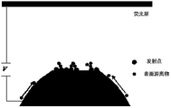
- the extraction electrode At the front of the electron source there is an extraction electrode, the extraction electrode is grounded, and the extraction stage itself can be a conductive fluorescent screen or an all-metal structure.
- the electron source is connected to the high-voltage power supply V EX ( ⁇ 30kV), which can apply an electric field to the electron source.
- V EX When V EX is negative, it can be used for field emission; when V EX is positive, it can be used for surface treatment such as field evaporation.
- the method of applying an electric field to the needle may also be that the electron source is grounded and the cascade is connected to a high-voltage power source. The method of applying the electric field is not limited herein.
- An electric field can be applied during the heat treatment.
- the heat treatment and the electric field can be applied synchronously or asynchronously.
- the electron source is placed on an insulator sample table (Insulator), and then connected to the cold head (Cold head). There is also a heating device on the insulator sample table, the adjustable temperature range is 10 ⁇ 500K.
- the working parameters of the electron source include working bias and any one or more of the following: working temperature or working pressure of the environment in which the electron source is located.
- 3A schematically shows a schematic diagram of the current emission capability of an electron source at a low temperature or room temperature in a high vacuum environment according to an embodiment of the present disclosure.
- the electron source is burned down after a stable operation for a certain period of time.
- the low temperature or room temperature may be 20-500K
- the high vacuum may be about 10-8 Pa.
- the electron source provided by the present disclosure exhibits typical field emission behavior, that is, its emission current increases significantly as the extraction voltage increases.
- Figure 3A shows the typical test results of the vacuum degree in the order of 10 -8 Pa, the applied voltage is still a constant negative high voltage ( ⁇ -2kV).
- the emission current is relatively stable. After a period of time, the emission current becomes unstable. After a period of time, the pattern will suddenly change or burn out. This behavior can be observed at temperatures ranging from 20 to 500K. The difference is that at low temperatures ( ⁇ 150K) the time that this process occurs significantly increases.
- FIG. 3B schematically shows a schematic diagram of an electron source burning process at a low temperature or room temperature in a high vacuum environment according to an embodiment of the present disclosure.
- the above burning may be due to the presence of free contaminants on the surface of the needle tip, and the corresponding schematic diagram is given in FIG. 3B.
- the free contaminants may be generated by the following two mechanisms: one is based on surface dissociation, and the other is based on ion bombardment during field emission.
- this free material is not fixed, and under the action of the external electric field, it will move to a high field strength and eventually accumulate in certain areas.
- the accumulated product can emit electrons even at a very low extraction voltage. According to a large number of experiments, during stable emission, this deposit can only give a small emission current; when the emission current is large (such as> 1uA), the fluctuation is large, which is easy to cause the electron source to burn.
- 3C schematically shows a schematic diagram of the current emission capability of an electron source at a low temperature or room temperature in a medium vacuum environment according to an embodiment of the present disclosure.
- the emission current of the electron source decreases significantly with the increase of working time. After a period of time, the emission current becomes unstable, and after a period of time, the burnout phenomenon may occur.
- the low temperature or room temperature may be 20 to 500K
- the medium vacuum may be about 10 -7 -10 -5 Pa.
- Figure 3C shows the typical test results of the needle tip under medium vacuum (10 -7 -10 -5 Pa), the applied voltage is still a constant negative high voltage ( ⁇ -2kV). The current drops significantly with time. After a period of time, the emission current becomes unstable, and it will burn out after a period of time. This behavior can be observed at both room temperature and low temperature.
- the difference is that at low temperatures ( ⁇ 150K) the time for this process to occur significantly increases. At the same time, at low temperatures, the slope SL of the current drop significantly slows down and tends to level. Burning is due to the impact of ion bombardment and surface dissociation. The current drop can basically be attributed to the effect of gas adsorption.
- FIG. 3D schematically shows a schematic diagram of current emission capability of an electron source at a high temperature in a vacuum environment according to an embodiment of the present disclosure.
- the electron source exhibits very different field emission behavior at higher operating temperatures (such as 500-800K). Specifically, the emission current of the electron source decreased significantly with the increase of working time, but there was no burnout. Among them, the high temperature may be 500-800K, and the medium vacuum may be about 10-5 Pa.
- Figure 3D shows the typical test results at a high temperature in a certain vacuum range ( ⁇ 10 -5 Pa), and the applied voltage is still a constant negative high voltage ( ⁇ -2kV). The current showed a certain decrease with time, but the slope of degradation (SL, the slope of degradation) was significantly slowed down relative to the needle tested at room temperature ( ⁇ 300K).
- FIG. 3E schematically shows a schematic diagram of adsorbing gas molecules on the surface of a needle tip according to an embodiment of the present disclosure.
- the surface of the emission point is a clean surface.
- the gas molecules adsorbed on the surface of the needle tip will gradually move to the emission point under the action of the electric field (for the emission point is formed in a high field strength structure On the surface, the field strength at the launch point is the highest).
- the working state of the electron source is mainly related to the vacuum degree and the working temperature.
- vacuum degree is directly related to the emission ability of the electron source. The better the vacuum degree, the better the stability, and the longer the continuous working time, and the emission ability is not easy to decline or degrade.
- the influence of the operating temperature is as follows: At an appropriate operating temperature, the slope SL of the emission current drop is significantly reduced, that is, the continuous working time can be extended, which is reflected in two aspects. In the first aspect, when working at low temperatures (eg, ⁇ 150K, relative to room temperature about 300K), the working time can be greatly extended. The second aspect, when working at higher temperatures (> 500K, relative to room temperature about 300K), the working time can be greatly extended.
- the electron source can work in the following environment: the working temperature ⁇ 1000K, and the working pressure ⁇ 10 -3 Pa.
- the electron source can be operated in the following environment: the working temperature ⁇ 150K, the working pressure ⁇ 1E -6 Pa, or, 500K ⁇ the working temperature ⁇ 800K, the working pressure ⁇ 1E -6 Pa.
- the adsorbed gas molecules can be separated from the surface of the electron source to restore the emission ability of the electron source. Specifically, it can be heated after working for a period of time (such as 0.1 to 10 hours) Desorption treatment. Among them, the higher the temperature, the more adequate the treatment.
- the emission point provided by the present disclosure is a reaction product of metal atoms and gas molecules on the surface of the needle tip, when treated at a high temperature for a long time, the emission point will disappear, for example, the reaction product may decompose.
- the present disclosure provides a heat treatment related method suitable for the above-mentioned electron source.
- the method may further include the following operations. First, heat treatment is performed on the electron source before or after the electron source emits electrons, and / or heat treatment is performed when the electron source emits electrons.
- the heat treatment of the electron source may include any one or more of the following methods: continuous heat treatment or pulse heat treatment. That is, in a state where the electron source is not emitting, it can be subjected to continuous heat treatment or pulse heat treatment.
- the heat treatment when the electron source emits electrons may include any one or more of the following methods: continuous heat treatment or pulse heat treatment. That is to say, in the state where the electron source emits, it can also be subjected to continuous heat treatment or pulse heat treatment.
- the continuous heating process may include the following operations: first, the electron source is continuously heated (for example, the electron source is energized to heat, or it may be heated by, for example, thermal radiation, etc., the heating method is here Not limited), wherein the heating temperature is lower than the small value of the electron source substrate, the metal atoms on the surface of the needle tip, and the disappearance temperature of the emission point, or, when the emission point is located on the electron source substrate
- the heating temperature is lower than the small value of the electron source substrate, the metal atoms on the surface of the needle tip, the emission point and the disappearance temperature of the high field strength structure, and then, maintaining the The temperature of the electron source until it reaches the first set duration.
- the heating temperature of the electron source may be ⁇ 800K
- the first set duration may be ⁇ 20min.
- the limitation of the heating temperature can effectively avoid the damage of the emission point, the metal atoms on the surface of the needle tip, the high field strength structure or the needle tip body.
- the first set duration can be determined according to the actual use effect.
- the first set duration is also related to the material type of the metal atom on the surface of the needle tip, the material type of the high field strength structure, etc.
- the metal atoms and the high field strength structure on the surface of the tip are less susceptible to heat treatment, as long as the heat treatment does not cause the emission point to disappear can.
- the needle tip may be supplemented with a bias voltage to prevent the deformation of the needle tip structure (such as a high field strength structure) resulting in a change in emission capability.
- the pair of electron sources supplemented with bias voltage includes any one or more of the following: supplemented with positive bias voltage, supplemented with negative bias voltage, or supplemented with a combination of positive bias voltage and negative bias voltage.
- the value of the positive bias when supplemented with a positive bias, is less than the voltage value corresponding to the field-induced evaporation at the emission point, or, when supplemented with a negative bias, the value of the negative bias is less than The voltage value corresponding to the first emission current threshold of the electron source (eg, no emission current is generated or excessive emission current is not generated).
- FIG. 4A schematically shows a schematic diagram of a medium continuous heat treatment mode according to an embodiment of the present disclosure.
- the heating temperature may be ⁇ 800K.
- the temperature range of ⁇ 800K such as passing current to a hairpin (the current value of which may be about several amperes A)
- the needle is heated.
- the device can refer to the device shown in FIG. 2.
- the treatment process generally lasts for several minutes (such as 0.1-20 minutes), and can also be extended according to the specific conditions of the needle tip.
- the first is to apply a positive bias mode (for example, the typical value can be 0.5 ⁇ 2kV), because there is no field emission current, so you can avoid the continuation of the needle tip due to the desorption gas excited by electrons Adsorption, but the absolute value of the maximum voltage when a positive bias is applied should be less than the field-induced evaporation voltage at the emission point of the needle tip;
- the second is to apply a negative bias, and the voltage range should be controlled so that the field emission of the needle tip is not significant, otherwise, The emitted electrons will excite the gas, which in turn causes adsorption to continue.
- the typical value of applying a negative bias voltage may be -0.5 to -1 kV.
- the pulse heating process may include the following operations: First, the electron source is heated in a pulse manner, wherein the period of the pulse ⁇ the pulse period threshold, and the interval duration between the pulse periods ⁇ interval
- the duration threshold specifically, the heating temperature is lower than the small value of the electron source substrate, the metal atoms on the surface of the needle tip, and the disappearance temperature of the emission point, or, when the emission point is located on the electron source substrate On a high field strength structure, the heating temperature is lower than the small value of the electron source substrate, the metal atoms on the surface of the needle tip, the emission point, and the disappearance temperature of the high field strength structure.
- the electron source can be biased in the continuous heating mode
- the electron source can also be biased in the pulse heating process.
- the assisting the electron source with a bias voltage includes any one or more of the following: assisting with a positive bias voltage, assisting with a negative bias voltage, or assisting with a combination of a positive bias voltage and a negative bias voltage.
- the value of the positive bias is less than the voltage value corresponding to the field-induced evaporation at the emission point, or, when supplemented with a negative bias, the value of the negative bias is less than the electron
- the voltage value corresponding to the first emission current threshold of the source For example, 0.5KV ⁇ the value of the positive bias voltage ⁇ 2KV, or -0.5KV ⁇ the value of the negative bias voltage ⁇ -1KV.
- FIG. 4B schematically shows a schematic diagram of a medium-pulse heating treatment mode according to an embodiment of the present disclosure.
- the bias voltage may or may not be applied.
- the medium temperature thermal pulse processing mode can be used, such as 500 ⁇ 1000K (the heating temperature can be different from the continuous heating temperature, the pulse mode can provide a temperature slightly higher than the continuous heating).
- each heating pulse can last for less than 10s, for example, 2 to 3 seconds, and multiple pulses can be used for processing. In order to avoid the mutual interference between the front and back pulses, the interval time between adjacent pulses can be increased, generally greater than 3 seconds.
- a bias voltage can be supplemented during the mid-temperature thermal pulse processing (the bias voltage can be positive or negative).
- the application period of the bias voltage may be the same as the pulse period of the pulse heating process, or the bias voltage may be applied during part or all of the pulse process, which is not limited herein.
- the needle tip protrusion may be damaged.
- the cumulative effect of long-term treatment will eventually cause the protrusion of the needle tip to deform, causing a significant drop in launching ability.
- a certain degree of bias (voltage) to the needle tip during heat treatment, deformation of the needle tip can be effectively avoided.
- the following two modes can be used: the first one, a positive bias voltage (typically 0.5 to 2 kV) can be applied, in which case the absolute value of the maximum voltage should be less than the field evaporation voltage of the point of emission on the surface of the needle tip (such as the HW reaction product) ;
- the second kind you can apply a negative bias, also need to control the voltage range, so that the field emission of the needle tip is not significant, otherwise, the emitted electrons will excite the gas, which will continue to lead to ion bombardment, when a negative bias is applied, it is generally typical
- the value can be from -0.5kV to -1kV.
- ion bombardment is a more serious problem, which is common in the launch process. This problem exists even in a small emission current and a good vacuum state, but the impact is only slight, and it is impossible to avoid it fundamentally. If not dealt with in time, the lifespan is hard to exceed 24 hours. It has been found through experiments that at the initial stage of the generation of such free material, the free material can be detached from the surface of the needle tip by a higher temperature treatment (for example,> -700K), wherein the higher the temperature, the more adequate the treatment. However, high temperature treatment for a long time will cause the emission point to disappear.
- a higher temperature treatment for example,> -700K
- the emission point is formed on the nano-scale protrusions, these protrusions will gradually deform at high temperature, resulting in a decline in emission capability, that is, a higher working voltage is required.
- the gas molecules adsorbed on the surface of the needle tip and the above-mentioned free substances can be effectively removed by the heat treatment method as described above, improving the situation that the emission ability of the electron source decreases with the increase of use time.
- FIG. 4C schematically shows a schematic diagram of heat treatment of an electron source to restore emission capability according to an embodiment of the present disclosure.
- the above-mentioned heat treatment can effectively restore the emission capability of the electron source.
- part of the emission point may be processed.
- the emission point may be formed again in the region where the emission point is removed to restore the initial emission state.
- a negative bias voltage is applied to form an emission point
- a negative bias voltage is applied to the needle tip to generate an emission current with a magnitude of microampere
- maintain a preset duration or adjust the negative bias voltage until a predetermined Value of the emission current
- adjust the negative bias voltage so that the emission current of the electron source is less than the order of milliampere, to avoid the change of the tip shape or burning.
- a positive bias voltage is applied to form an emission point, a positive bias voltage is applied to the needle tip and maintained for a preset duration, and the value of the positive bias voltage is less than the value of the field-induced evaporation bias voltage forming the protrusion.
- the formed field strength range includes 1-50V / nm
- the formed field strength range includes 1-30V / nm.
- FIG. 4D schematically shows a flowchart of a needle tip operation mode according to an embodiment of the present disclosure.
- the working mode shown in FIG. 4C may be adopted.
- the electron source works under a certain voltage, and after a period of emission, the emission ability decreases (ie, the field emission current decreases at the same voltage), and the recovery of the needle tip of the electron source (Recovering treatment) can be eliminated.
- the restorative treatment may include the aforementioned medium-temperature continuous heating treatment mode (which may or may not be biased) and / or medium-temperature heat pulse treatment mode (which may or may not be biased). After the treatment, the emission capability is restored, Can continue to work. In other words, the above emission cycle and recovery processing cycle are repeated continuously, so that the electron source can work stably for a long time.
- the electron source can be operated in the following temperature range.
- the first is low temperature operation (eg ⁇ 150K), and the second is higher temperature operation (eg> 500K).
- the medium temperature continuous heating mode and / or the medium temperature thermal pulse processing mode can also be performed during the emission period (Emission period) to simultaneously eliminate gas adsorption and ion bombardment.
- the following treatment methods can be included: the first, medium temperature continuous heating treatment mode: temperature ⁇ 800K; the second, medium temperature heat pulse treatment mode: 500 ⁇ 1000K (pulse mode);
- a bias can be applied to the needle simultaneously to prevent deformation.
- an electron source as described above can be continuously operated for more than 1000 hours, greatly improving the service life of the electron source, and still maintaining a good emission state, for example,
- the outgoing voltage is only increased by less than 200 volts from the beginning.
- FIG. 5 schematically shows a schematic diagram of the aging of the launch ability of the needle tip according to an embodiment of the present disclosure after long-term operation.
- the electron source when the electron source runs for a long period of time (such as the 1000th use cycle, about 1000 hours), the emission capability of the electron source is partially aging, that is, under a certain voltage, the electron The maximum emission capability of the source is lower than the emission capability of the first cycle and cannot be recovered.
- the electron source can still be repaired to a large extent by heat treatment.
- the medium-temperature continuous heating treatment mode (which can be biased or not added), and the medium-temperature heat pulse treatment mode (which can be biased or not added) make repairs.
- the interval continuous heating or pulse heating can be used to increase the temperature during repair, or the continuous heating or pulse heating can be used to increase the temperature during work, and the working temperature can also be increased during the work. It should be emphasized that the conditions for the repair of the electronic source are not limited and can be customized by the user.
- the method may further include the following operation: repairing the emission point of the electron source.
- the repairing of the emission point of the electron source may include the following operations: first, removing at least one emission point on the surface of the needle tip of the electron source, and then, forming a new emission point on the surface of the needle tip, the new The emission point is the reaction product formed by the metal atoms and gas molecules on the surface of the needle tip under the electric field.
- interval heating can be used to increase the temperature, or heating to increase the temperature during work, and in addition, the working temperature can be increased during the work.
- the removing at least one emission point on the surface of the electron source tip may include the following operations, for example, removing at least one emission point on the surface of the electron source by heating or field evaporation, wherein When at least one emission point on the surface of the electron source, the heating temperature is lower than the small value of the disappearance temperature of the metal atoms on the surface of the electron source substrate and the needle tip, or, when the emission point is at a high level of the electron source substrate When the field strength structure is on, the heating temperature is lower than the small value of the electron source substrate, the metal atoms on the surface of the needle tip, and the disappearance temperature of the high field strength structure.
- the electron source may be supplemented with a bias voltage
- the supplementary bias voltage for the electron source includes any one or more of the following: supplemented with a positive bias voltage, supplemented with a negative bias voltage, or supplemented Combine positive and negative bias.
- the value of the positive bias applied by the field evaporation is lower than that corresponding to the disappearance of the metal atoms on the surface of the electron source substrate and the needle tip Small value, or, when the emission point is located on the high field strength structure of the electron source substrate, the value of the positive bias applied by the field-induced evaporation is lower than that of the electron source substrate and the metal on the surface of the needle tip.
- the temperature and frequency of each heat treatment pulse should be increased (such as hundreds of times) to remove the emission point of the aging of the emission ability on the surface, or the emission point of the aging of the emission ability of the surface (positive bias)
- the pressure value should not completely evaporate the protrusion); afterwards, the emission point can be formed again on the surface of the needle tip by means of re-growth.
- the temperature of the heat pulse should not exceed 1000K, otherwise it will easily cause the destruction of the protrusion on the surface of the needle tip, and this requires the use of a new electron source.
- the most reliable method is to operate under high vacuum ( ⁇ 10 -7 Pa). If it is under a worse vacuum, the working current must be reduced to ensure the running time.
- the solution for burning the needle tip is as follows.
- the working temperature is 500K ⁇ 800K, which can effectively avoid burning. This temperature range can avoid the formation of surface dissociation.
- higher temperatures such as> 1000K, the emission point of the above electron source will disappear for a long time, for example, it will cause the decomposition of the reaction product of tungsten atoms and gas molecules.
- the working temperature is ⁇ 150K
- effectively reducing the temperature can delay the movement of free matter (whether generated by ion bombardment or surface dissociation) to the emission area, and at the same time, the needle tip cooling also It can improve the local vacuum of the needle tip, and also help to delay burnout.
- the above heat treatment to improve the gas adsorption problem can improve the gas adsorption problem, and can effectively improve the burning problem caused by ion bombardment and surface dissociation; at the same time, provide A higher vacuum degree can also greatly reduce the probability of gas adsorption and thus improve the gas adsorption problem; providing a higher working temperature or a lower working temperature can also improve the gas adsorption problem.
- the emission point is a hydrogen tungsten compound.
- the extraction voltage of the hydrogen tungsten compound as the emission point is low, so that the yield of ion bombardment of free materials is low, the energy is low, and the movement speed to the emission zone is slow, and the burning can also be delayed.
Landscapes
- Chemical & Material Sciences (AREA)
- Analytical Chemistry (AREA)
- Engineering & Computer Science (AREA)
- Manufacturing & Machinery (AREA)
- Cold Cathode And The Manufacture (AREA)
- Electron Sources, Ion Sources (AREA)
Priority Applications (4)
| Application Number | Priority Date | Filing Date | Title |
|---|---|---|---|
| JP2020542130A JP6959457B2 (ja) | 2018-10-12 | 2018-12-27 | 電子源動作方法 |
| US16/966,910 US11430625B2 (en) | 2018-10-12 | 2018-12-27 | Electron source operating method |
| EP18936479.7A EP3770944A4 (en) | 2018-10-12 | 2018-12-27 | OPERATING PROCESS OF AN ELECTRON SOURCE |
| KR1020207022430A KR102469975B1 (ko) | 2018-10-12 | 2018-12-27 | 전자 소스 동작 방법 |
Applications Claiming Priority (2)
| Application Number | Priority Date | Filing Date | Title |
|---|---|---|---|
| CN201811190748.7 | 2018-10-12 | ||
| CN201811190748.7A CN111048372B (zh) | 2018-10-12 | 2018-10-12 | 一种电子源工作方法 |
Publications (1)
| Publication Number | Publication Date |
|---|---|
| WO2020073512A1 true WO2020073512A1 (zh) | 2020-04-16 |
Family
ID=70164171
Family Applications (1)
| Application Number | Title | Priority Date | Filing Date |
|---|---|---|---|
| PCT/CN2018/124331 Ceased WO2020073512A1 (zh) | 2018-10-12 | 2018-12-27 | 一种电子源工作方法 |
Country Status (7)
| Country | Link |
|---|---|
| US (1) | US11430625B2 (enExample) |
| EP (1) | EP3770944A4 (enExample) |
| JP (1) | JP6959457B2 (enExample) |
| KR (1) | KR102469975B1 (enExample) |
| CN (1) | CN111048372B (enExample) |
| TW (2) | TW202020919A (enExample) |
| WO (1) | WO2020073512A1 (enExample) |
Families Citing this family (1)
| Publication number | Priority date | Publication date | Assignee | Title |
|---|---|---|---|---|
| US11335529B2 (en) * | 2020-06-19 | 2022-05-17 | The Government Of The United States Of America, As Represented By The Secretary Of The Navy | Thermally enhanced compound field emitter |
Citations (6)
| Publication number | Priority date | Publication date | Assignee | Title |
|---|---|---|---|---|
| JPH07192669A (ja) * | 1993-12-27 | 1995-07-28 | Jeol Ltd | 電界電離型ガスフェーズイオン源の調整方法 |
| US7431856B2 (en) * | 2005-05-18 | 2008-10-07 | National Research Council Of Canada | Nano-tip fabrication by spatially controlled etching |
| CN102789946A (zh) * | 2011-05-16 | 2012-11-21 | 中国电子科技集团公司第三十八研究所 | 粒子源及其制造方法 |
| CN102789947A (zh) * | 2011-05-16 | 2012-11-21 | 中国电子科技集团公司第三十八研究所 | 粒子源及其制造方法 |
| CN104704601A (zh) * | 2012-10-12 | 2015-06-10 | 株式会社日立高新技术 | 电子源的制造方法 |
| CN105140091A (zh) * | 2015-07-27 | 2015-12-09 | 北京中科科仪股份有限公司 | 一种场发射电子枪烘烤装置和一种电子枪室的烘烤方法 |
Family Cites Families (15)
| Publication number | Priority date | Publication date | Assignee | Title |
|---|---|---|---|---|
| JPS5912533A (ja) | 1982-07-12 | 1984-01-23 | Hitachi Ltd | 拡散補給形電子線源 |
| US6281626B1 (en) * | 1998-03-24 | 2001-08-28 | Casio Computer Co., Ltd. | Cold emission electrode method of manufacturing the same and display device using the same |
| US6573642B1 (en) * | 2000-01-26 | 2003-06-03 | Motorola, Inc. | Field emission device and method for the conditioning thereof |
| JP2003100244A (ja) * | 2001-09-26 | 2003-04-04 | Jeol Ltd | 電子ビーム源 |
| CN102394204B (zh) | 2008-03-19 | 2014-10-08 | 清华大学 | 场发射电子源 |
| JP2011065790A (ja) * | 2009-09-15 | 2011-03-31 | Tokyo Electron Ltd | 電子源、電子源の製造方法及び電子放出方法 |
| JP5455700B2 (ja) | 2010-02-18 | 2014-03-26 | 株式会社日立ハイテクノロジーズ | 電界放出電子銃及びその制御方法 |
| JP5363413B2 (ja) | 2010-05-10 | 2013-12-11 | 電気化学工業株式会社 | 電子源 |
| US8736170B1 (en) * | 2011-02-22 | 2014-05-27 | Fei Company | Stable cold field emission electron source |
| CN102842474B (zh) * | 2011-06-22 | 2015-11-25 | 中国电子科技集团公司第三十八研究所 | 粒子源及其制造方法 |
| CN102629538B (zh) * | 2012-04-13 | 2014-03-19 | 吴江炀晟阴极材料有限公司 | 具有低逸出功和高化学稳定性的电极材料 |
| US8952605B2 (en) | 2012-07-03 | 2015-02-10 | National Institute For Materials Science | Metal hexaboride cold field emitter, method of fabricating same, and electron gun |
| JP6266458B2 (ja) * | 2013-08-09 | 2018-01-24 | 株式会社日立ハイテクサイエンス | イリジウムティップ、ガス電界電離イオン源、集束イオンビーム装置、電子源、電子顕微鏡、電子ビーム応用分析装置、イオン電子複合ビーム装置、走査プローブ顕微鏡、およびマスク修正装置 |
| US10133181B2 (en) | 2015-08-14 | 2018-11-20 | Kla-Tencor Corporation | Electron source |
| US9984846B2 (en) | 2016-06-30 | 2018-05-29 | Kla-Tencor Corporation | High brightness boron-containing electron beam emitters for use in a vacuum environment |
-
2018
- 2018-10-12 CN CN201811190748.7A patent/CN111048372B/zh active Active
- 2018-12-27 JP JP2020542130A patent/JP6959457B2/ja active Active
- 2018-12-27 EP EP18936479.7A patent/EP3770944A4/en not_active Withdrawn
- 2018-12-27 KR KR1020207022430A patent/KR102469975B1/ko active Active
- 2018-12-27 US US16/966,910 patent/US11430625B2/en active Active
- 2018-12-27 WO PCT/CN2018/124331 patent/WO2020073512A1/zh not_active Ceased
-
2019
- 2019-10-08 TW TW108136469A patent/TW202020919A/zh unknown
- 2019-10-14 TW TW108136929A patent/TWI729527B/zh active
Patent Citations (6)
| Publication number | Priority date | Publication date | Assignee | Title |
|---|---|---|---|---|
| JPH07192669A (ja) * | 1993-12-27 | 1995-07-28 | Jeol Ltd | 電界電離型ガスフェーズイオン源の調整方法 |
| US7431856B2 (en) * | 2005-05-18 | 2008-10-07 | National Research Council Of Canada | Nano-tip fabrication by spatially controlled etching |
| CN102789946A (zh) * | 2011-05-16 | 2012-11-21 | 中国电子科技集团公司第三十八研究所 | 粒子源及其制造方法 |
| CN102789947A (zh) * | 2011-05-16 | 2012-11-21 | 中国电子科技集团公司第三十八研究所 | 粒子源及其制造方法 |
| CN104704601A (zh) * | 2012-10-12 | 2015-06-10 | 株式会社日立高新技术 | 电子源的制造方法 |
| CN105140091A (zh) * | 2015-07-27 | 2015-12-09 | 北京中科科仪股份有限公司 | 一种场发射电子枪烘烤装置和一种电子枪室的烘烤方法 |
Non-Patent Citations (1)
| Title |
|---|
| See also references of EP3770944A4 * |
Also Published As
| Publication number | Publication date |
|---|---|
| TW202020919A (zh) | 2020-06-01 |
| US20210050172A1 (en) | 2021-02-18 |
| US11430625B2 (en) | 2022-08-30 |
| TWI729527B (zh) | 2021-06-01 |
| JP2021512469A (ja) | 2021-05-13 |
| EP3770944A4 (en) | 2021-08-11 |
| KR20200105891A (ko) | 2020-09-09 |
| JP6959457B2 (ja) | 2021-11-02 |
| KR102469975B1 (ko) | 2022-11-23 |
| EP3770944A1 (en) | 2021-01-27 |
| CN111048372A (zh) | 2020-04-21 |
| TW202015088A (zh) | 2020-04-16 |
| CN111048372B (zh) | 2021-04-27 |
Similar Documents
| Publication | Publication Date | Title |
|---|---|---|
| JP5301168B2 (ja) | 冷電界エミッタ | |
| Schwoebel et al. | Field‐emitter array performance enhancement using hydrogen glow discharges | |
| TWI747058B (zh) | 電子源製造方法 | |
| EP3736848B1 (en) | Electron source and electron gun | |
| TWI729527B (zh) | 電子源工作方法 | |
| TW201737285A (zh) | 間接加熱式陰極離子源與用於離子源室內的斥拒極 | |
| TWI738079B (zh) | 電子源再生方法 | |
| Minami et al. | Real-time microscopic observation of emission fluctuation on Mo-tip field emitter array caused by introduced gas | |
| JP2010257854A (ja) | イオンビーム装置 |
Legal Events
| Date | Code | Title | Description |
|---|---|---|---|
| 121 | Ep: the epo has been informed by wipo that ep was designated in this application |
Ref document number: 18936479 Country of ref document: EP Kind code of ref document: A1 |
|
| ENP | Entry into the national phase |
Ref document number: 20207022430 Country of ref document: KR Kind code of ref document: A Ref document number: 2020542130 Country of ref document: JP Kind code of ref document: A |
|
| ENP | Entry into the national phase |
Ref document number: 2018936479 Country of ref document: EP Effective date: 20200803 |
|
| NENP | Non-entry into the national phase |
Ref country code: DE |