EP3736848B1 - Electron source and electron gun - Google Patents
Electron source and electron gun Download PDFInfo
- Publication number
- EP3736848B1 EP3736848B1 EP18936834.3A EP18936834A EP3736848B1 EP 3736848 B1 EP3736848 B1 EP 3736848B1 EP 18936834 A EP18936834 A EP 18936834A EP 3736848 B1 EP3736848 B1 EP 3736848B1
- Authority
- EP
- European Patent Office
- Prior art keywords
- base
- field strength
- tip
- emission
- electron source
- Prior art date
- Legal status (The legal status is an assumption and is not a legal conclusion. Google has not performed a legal analysis and makes no representation as to the accuracy of the status listed.)
- Active
Links
- 239000007789 gas Substances 0.000 claims description 125
- 229910052751 metal Inorganic materials 0.000 claims description 117
- 239000002184 metal Substances 0.000 claims description 117
- 238000006243 chemical reaction Methods 0.000 claims description 46
- 239000007795 chemical reaction product Substances 0.000 claims description 43
- 230000005684 electric field Effects 0.000 claims description 35
- 239000000463 material Substances 0.000 claims description 35
- 230000000694 effects Effects 0.000 claims description 32
- 238000010438 heat treatment Methods 0.000 claims description 25
- WFKWXMTUELFFGS-UHFFFAOYSA-N tungsten Chemical compound [W] WFKWXMTUELFFGS-UHFFFAOYSA-N 0.000 claims description 20
- UFHFLCQGNIYNRP-UHFFFAOYSA-N Hydrogen Chemical compound [H][H] UFHFLCQGNIYNRP-UHFFFAOYSA-N 0.000 claims description 19
- 239000004020 conductor Substances 0.000 claims description 17
- 229910052721 tungsten Inorganic materials 0.000 claims description 17
- 239000010937 tungsten Substances 0.000 claims description 17
- 229910052739 hydrogen Inorganic materials 0.000 claims description 16
- 239000001257 hydrogen Substances 0.000 claims description 16
- 238000002844 melting Methods 0.000 claims description 16
- 230000008018 melting Effects 0.000 claims description 16
- 238000001816 cooling Methods 0.000 claims description 12
- 239000007769 metal material Substances 0.000 claims description 9
- 125000004429 atom Chemical group 0.000 description 98
- 238000000034 method Methods 0.000 description 43
- 230000008569 process Effects 0.000 description 26
- 230000015572 biosynthetic process Effects 0.000 description 22
- 230000008034 disappearance Effects 0.000 description 14
- 230000008901 benefit Effects 0.000 description 13
- 238000000605 extraction Methods 0.000 description 12
- 239000000126 substance Substances 0.000 description 12
- 230000008859 change Effects 0.000 description 11
- 238000001704 evaporation Methods 0.000 description 11
- 238000010849 ion bombardment Methods 0.000 description 10
- 239000010410 layer Substances 0.000 description 10
- 239000013078 crystal Substances 0.000 description 9
- 230000008020 evaporation Effects 0.000 description 9
- 238000001179 sorption measurement Methods 0.000 description 8
- 238000009713 electroplating Methods 0.000 description 7
- 239000002245 particle Substances 0.000 description 7
- 238000003795 desorption Methods 0.000 description 6
- 238000002360 preparation method Methods 0.000 description 6
- 238000004140 cleaning Methods 0.000 description 5
- 238000011282 treatment Methods 0.000 description 5
- 238000013461 design Methods 0.000 description 4
- 238000010894 electron beam technology Methods 0.000 description 4
- 238000005530 etching Methods 0.000 description 4
- BASFCYQUMIYNBI-UHFFFAOYSA-N platinum Chemical compound [Pt] BASFCYQUMIYNBI-UHFFFAOYSA-N 0.000 description 4
- 230000009471 action Effects 0.000 description 3
- 238000000137 annealing Methods 0.000 description 3
- 150000001875 compounds Chemical class 0.000 description 3
- 230000007423 decrease Effects 0.000 description 3
- 230000007246 mechanism Effects 0.000 description 3
- KDLHZDBZIXYQEI-UHFFFAOYSA-N Palladium Chemical compound [Pd] KDLHZDBZIXYQEI-UHFFFAOYSA-N 0.000 description 2
- RTAQQCXQSZGOHL-UHFFFAOYSA-N Titanium Chemical compound [Ti] RTAQQCXQSZGOHL-UHFFFAOYSA-N 0.000 description 2
- 238000000354 decomposition reaction Methods 0.000 description 2
- 230000003247 decreasing effect Effects 0.000 description 2
- 230000007547 defect Effects 0.000 description 2
- -1 hydrogen tungsten compound Chemical class 0.000 description 2
- 230000010354 integration Effects 0.000 description 2
- 238000003754 machining Methods 0.000 description 2
- 150000002736 metal compounds Chemical class 0.000 description 2
- 238000007747 plating Methods 0.000 description 2
- 229910052697 platinum Inorganic materials 0.000 description 2
- 238000012545 processing Methods 0.000 description 2
- 230000009467 reduction Effects 0.000 description 2
- 238000011160 research Methods 0.000 description 2
- 239000007787 solid Substances 0.000 description 2
- 229910052719 titanium Inorganic materials 0.000 description 2
- 239000010936 titanium Substances 0.000 description 2
- ZOKXTWBITQBERF-UHFFFAOYSA-N Molybdenum Chemical compound [Mo] ZOKXTWBITQBERF-UHFFFAOYSA-N 0.000 description 1
- KJTLSVCANCCWHF-UHFFFAOYSA-N Ruthenium Chemical compound [Ru] KJTLSVCANCCWHF-UHFFFAOYSA-N 0.000 description 1
- QCWXUUIWCKQGHC-UHFFFAOYSA-N Zirconium Chemical compound [Zr] QCWXUUIWCKQGHC-UHFFFAOYSA-N 0.000 description 1
- 230000001133 acceleration Effects 0.000 description 1
- 238000004458 analytical method Methods 0.000 description 1
- 230000000903 blocking effect Effects 0.000 description 1
- SEGDSKBQYPCVFK-UHFFFAOYSA-N chromium hafnium Chemical compound [Cr][Hf] SEGDSKBQYPCVFK-UHFFFAOYSA-N 0.000 description 1
- 230000002301 combined effect Effects 0.000 description 1
- 239000000356 contaminant Substances 0.000 description 1
- 238000011109 contamination Methods 0.000 description 1
- 238000007872 degassing Methods 0.000 description 1
- 238000011161 development Methods 0.000 description 1
- 230000009977 dual effect Effects 0.000 description 1
- 238000005516 engineering process Methods 0.000 description 1
- 230000007613 environmental effect Effects 0.000 description 1
- 230000005284 excitation Effects 0.000 description 1
- 238000002474 experimental method Methods 0.000 description 1
- 239000003574 free electron Substances 0.000 description 1
- PCHJSUWPFVWCPO-UHFFFAOYSA-N gold Chemical compound [Au] PCHJSUWPFVWCPO-UHFFFAOYSA-N 0.000 description 1
- 229910052737 gold Inorganic materials 0.000 description 1
- 239000010931 gold Substances 0.000 description 1
- 238000003384 imaging method Methods 0.000 description 1
- 238000011065 in-situ storage Methods 0.000 description 1
- 238000010884 ion-beam technique Methods 0.000 description 1
- 150000002500 ions Chemical class 0.000 description 1
- 229910052741 iridium Inorganic materials 0.000 description 1
- GKOZUEZYRPOHIO-UHFFFAOYSA-N iridium atom Chemical compound [Ir] GKOZUEZYRPOHIO-UHFFFAOYSA-N 0.000 description 1
- 230000007774 longterm Effects 0.000 description 1
- 238000002156 mixing Methods 0.000 description 1
- 229910052750 molybdenum Inorganic materials 0.000 description 1
- 239000011733 molybdenum Substances 0.000 description 1
- 229910052758 niobium Inorganic materials 0.000 description 1
- 239000010955 niobium Substances 0.000 description 1
- GUCVJGMIXFAOAE-UHFFFAOYSA-N niobium atom Chemical compound [Nb] GUCVJGMIXFAOAE-UHFFFAOYSA-N 0.000 description 1
- 229910052755 nonmetal Inorganic materials 0.000 description 1
- 229910052762 osmium Inorganic materials 0.000 description 1
- SYQBFIAQOQZEGI-UHFFFAOYSA-N osmium atom Chemical compound [Os] SYQBFIAQOQZEGI-UHFFFAOYSA-N 0.000 description 1
- 229910052763 palladium Inorganic materials 0.000 description 1
- 239000000047 product Substances 0.000 description 1
- 230000002035 prolonged effect Effects 0.000 description 1
- 230000001737 promoting effect Effects 0.000 description 1
- 239000011241 protective layer Substances 0.000 description 1
- 239000012495 reaction gas Substances 0.000 description 1
- 230000008439 repair process Effects 0.000 description 1
- 229910052702 rhenium Inorganic materials 0.000 description 1
- WUAPFZMCVAUBPE-UHFFFAOYSA-N rhenium atom Chemical compound [Re] WUAPFZMCVAUBPE-UHFFFAOYSA-N 0.000 description 1
- 229910052703 rhodium Inorganic materials 0.000 description 1
- 239000010948 rhodium Substances 0.000 description 1
- MHOVAHRLVXNVSD-UHFFFAOYSA-N rhodium atom Chemical compound [Rh] MHOVAHRLVXNVSD-UHFFFAOYSA-N 0.000 description 1
- 229910052707 ruthenium Inorganic materials 0.000 description 1
- 238000003860 storage Methods 0.000 description 1
- 238000005728 strengthening Methods 0.000 description 1
- 229910052715 tantalum Inorganic materials 0.000 description 1
- GUVRBAGPIYLISA-UHFFFAOYSA-N tantalum atom Chemical compound [Ta] GUVRBAGPIYLISA-UHFFFAOYSA-N 0.000 description 1
- 238000012360 testing method Methods 0.000 description 1
- 238000012876 topography Methods 0.000 description 1
- 229910052720 vanadium Inorganic materials 0.000 description 1
- GPPXJZIENCGNKB-UHFFFAOYSA-N vanadium Chemical compound [V]#[V] GPPXJZIENCGNKB-UHFFFAOYSA-N 0.000 description 1
- 229910052726 zirconium Inorganic materials 0.000 description 1
Images


Classifications
-
- H—ELECTRICITY
- H01—ELECTRIC ELEMENTS
- H01J—ELECTRIC DISCHARGE TUBES OR DISCHARGE LAMPS
- H01J37/00—Discharge tubes with provision for introducing objects or material to be exposed to the discharge, e.g. for the purpose of examination or processing thereof
- H01J37/02—Details
- H01J37/04—Arrangements of electrodes and associated parts for generating or controlling the discharge, e.g. electron-optical arrangement, ion-optical arrangement
- H01J37/06—Electron sources; Electron guns
- H01J37/065—Construction of guns or parts thereof
-
- H—ELECTRICITY
- H01—ELECTRIC ELEMENTS
- H01J—ELECTRIC DISCHARGE TUBES OR DISCHARGE LAMPS
- H01J37/00—Discharge tubes with provision for introducing objects or material to be exposed to the discharge, e.g. for the purpose of examination or processing thereof
- H01J37/02—Details
- H01J37/04—Arrangements of electrodes and associated parts for generating or controlling the discharge, e.g. electron-optical arrangement, ion-optical arrangement
- H01J37/06—Electron sources; Electron guns
- H01J37/073—Electron guns using field emission, photo emission, or secondary emission electron sources
-
- H—ELECTRICITY
- H01—ELECTRIC ELEMENTS
- H01J—ELECTRIC DISCHARGE TUBES OR DISCHARGE LAMPS
- H01J37/00—Discharge tubes with provision for introducing objects or material to be exposed to the discharge, e.g. for the purpose of examination or processing thereof
- H01J37/02—Details
- H01J37/04—Arrangements of electrodes and associated parts for generating or controlling the discharge, e.g. electron-optical arrangement, ion-optical arrangement
- H01J37/06—Electron sources; Electron guns
-
- H—ELECTRICITY
- H01—ELECTRIC ELEMENTS
- H01J—ELECTRIC DISCHARGE TUBES OR DISCHARGE LAMPS
- H01J1/00—Details of electrodes, of magnetic control means, of screens, or of the mounting or spacing thereof, common to two or more basic types of discharge tubes or lamps
- H01J1/02—Main electrodes
- H01J1/30—Cold cathodes, e.g. field-emissive cathode
- H01J1/304—Field-emissive cathodes
- H01J1/3048—Distributed particle emitters
-
- H—ELECTRICITY
- H01—ELECTRIC ELEMENTS
- H01J—ELECTRIC DISCHARGE TUBES OR DISCHARGE LAMPS
- H01J3/00—Details of electron-optical or ion-optical arrangements or of ion traps common to two or more basic types of discharge tubes or lamps
- H01J3/02—Electron guns
- H01J3/021—Electron guns using a field emission, photo emission, or secondary emission electron source
-
- H—ELECTRICITY
- H01—ELECTRIC ELEMENTS
- H01J—ELECTRIC DISCHARGE TUBES OR DISCHARGE LAMPS
- H01J37/00—Discharge tubes with provision for introducing objects or material to be exposed to the discharge, e.g. for the purpose of examination or processing thereof
- H01J37/02—Details
- H01J37/04—Arrangements of electrodes and associated parts for generating or controlling the discharge, e.g. electron-optical arrangement, ion-optical arrangement
- H01J37/06—Electron sources; Electron guns
- H01J37/07—Eliminating deleterious effects due to thermal effects or electric or magnetic fields
-
- H—ELECTRICITY
- H01—ELECTRIC ELEMENTS
- H01J—ELECTRIC DISCHARGE TUBES OR DISCHARGE LAMPS
- H01J2201/00—Electrodes common to discharge tubes
- H01J2201/30—Cold cathodes
- H01J2201/304—Field emission cathodes
- H01J2201/30403—Field emission cathodes characterised by the emitter shape
- H01J2201/30426—Coatings on the emitter surface, e.g. with low work function materials
-
- H—ELECTRICITY
- H01—ELECTRIC ELEMENTS
- H01J—ELECTRIC DISCHARGE TUBES OR DISCHARGE LAMPS
- H01J2201/00—Electrodes common to discharge tubes
- H01J2201/30—Cold cathodes
- H01J2201/304—Field emission cathodes
- H01J2201/30403—Field emission cathodes characterised by the emitter shape
- H01J2201/30438—Particles
-
- H—ELECTRICITY
- H01—ELECTRIC ELEMENTS
- H01J—ELECTRIC DISCHARGE TUBES OR DISCHARGE LAMPS
- H01J2201/00—Electrodes common to discharge tubes
- H01J2201/30—Cold cathodes
- H01J2201/304—Field emission cathodes
- H01J2201/30446—Field emission cathodes characterised by the emitter material
- H01J2201/30449—Metals and metal alloys
-
- H—ELECTRICITY
- H01—ELECTRIC ELEMENTS
- H01J—ELECTRIC DISCHARGE TUBES OR DISCHARGE LAMPS
- H01J2237/00—Discharge tubes exposing object to beam, e.g. for analysis treatment, etching, imaging
- H01J2237/002—Cooling arrangements
-
- H—ELECTRICITY
- H01—ELECTRIC ELEMENTS
- H01J—ELECTRIC DISCHARGE TUBES OR DISCHARGE LAMPS
- H01J2237/00—Discharge tubes exposing object to beam, e.g. for analysis treatment, etching, imaging
- H01J2237/06—Sources
- H01J2237/063—Electron sources
- H01J2237/06325—Cold-cathode sources
- H01J2237/06341—Field emission
- H01J2237/0635—Multiple source, e.g. comb or array
Definitions
- the present disclosure relates to the field of electron source technology, and in particular, to a field emission electron source and a field emission electron gun.
- Free electrons in metal may be emitted under certain conditions. If a cathode is made of metal and made into a very fine tip and it is applied by a voltage of thousands of volts in a vacuum, then the electrons in the metal may be emitted from the cathode cold metal. This method of emitting electrons is called as field emission, belonging to cold cathode emission.
- the most important parameter is brightness, which directly determines the beam quality.
- B refers to the brightness
- I refers to an emission current
- S refers to an equivalent emission area
- d refers to an equivalent diameter
- ⁇ refers to a solid angle
- ⁇ refers to an half opening angle.
- the brightness B is proportional to an acceleration voltage V a , as shown in the formula (2).
- the most ideal electron source is the cold field emission electron source (abbreviated as CFE).
- CFE cold field emission electron source
- the brightness of CFE is higher than that of other types of electron sources by about one order of magnitude, and it has a small energy spread ( ⁇ 0.3eV).
- atomic-scale electron sources having a low work function recently have become the research hotspots, that is, the emission site consists of only one or several atoms.
- the inventors have found that the CFE in the prior art has at least the following disadvantages: firstly, the stability of the CFE is often poor, and it is required to work under extremely high vacuum (10 -9 ⁇ 10 -8 Pa), which severely limits the scope of application thereof. Even in such an environment, it needs to be processed regularly to obtain a more stable working state. Secondly, due to the impact of ion bombardment, the CFE is easier to be burned out. Thirdly, the aforementioned disadvantages become more serious at a larger emission current, the current CFE generally needs a total emission current of ⁇ 10 microamperes for stable operation for a long time, and the utilization rate thereof is very low. In view of the aforementioned drawbacks, the Schottky thermal-field emission source is dominant in the field of high-brightness electron sources.
- the present disclosure provides a stable electron source and electron gun which have a large field emission current and can operate at a relatively poor vacuum degree.
- an electron source as defined in claim 1 comprising one or more tips, wherein at least one of the tips comprises one or more fixed emission sites, wherein the emission sites comprises a reaction product of metal atoms on a surface of the tip with gas molecules.
- a metal atom material comprises tungsten and the gas molecules comprise hydrogen-containing gas molecules.
- the emission site is a reaction product of metal atoms fixed on the surface of the tip with gas molecules, it is rooted in the surface of the tip, rather than gas molecules, dissociative particles or the like that are dissociative on the surface of the tip. It would not incur over-current burnout due to that the dissociative emission sites gather together to form a new emission site, thereby effectively improving stability.
- the emission site comprises the reaction product of the metal atoms on the surface of the tip with the gas molecules, in comparison with metal atoms or other metal compounds (such as metal boride or the like), it has higher stability in the working environment (with the presence of gas molecules), for example, being less likely to interact or react with, for example, hydrogen in the working environment, further improving the stability of the electron source.
- the emission site of the electron source provided by the present disclosure may be a reaction product of one or several metal atoms with gas molecules, that is, an atomic-scale electron source having a low work function may be formed.
- the reaction product significantly reduces the surface work function, and the formation of the pointed cone of the surface emission site also significantly increases the emission capability.
- the current value of the field emission current may be increased by increasing the number of the emission sites. In this way, it is possible to form a stable electron source with a large field emission current.
- the emission sites comprise a reaction product of the metal atoms with the gas molecules under an electric field. This facilitates the formation of the emission site at a designated position of the tip, particularly at a position where it has an electric field advantage, for example, at a protrusion of the tip.
- At least one of the tips comprises a base and one or more high field strength structures on the base having a higher field strength than that of other portions of the base, and an outer surface of at least one of the high field strength structures comprises metal atoms.
- the metal atoms on the surface of the high field strength structure are more likely to react with the gas molecules to form a reaction product in the same environment by virtue of the field strength advantage, so as to preferentially generate the emission site on the high field strength structure.
- at least one of the tips comprises a base and one or more active regions on the base having a larger reaction activity than that of other portions of the base, and an outer surface of at least one of the active regions comprises metal atoms.
- the metal atoms on the surface of the active region are more likely to react with the gas molecules to form a reaction product in the same environment by virtue of the activity advantage, so as to preferentially generate the emission site at the active region.
- at least one of the tips comprises a base and one or more high field strength structures on the base having a higher field strength than that of other portions of the base, at least a portion of surfaces of the high field strength structures are active regions having a larger reaction activity, and outer surfaces of the active regions comprise metal atoms.
- the metal atoms on the surface of the active region are more likely to react with the gas molecules to form a reaction product in the same environment by virtue of the field strength advantage and the activity advantage, so as to preferentially generate the emission site at the active region.
- the electric field is generated by applying a positive bias, a negative bias, or a combination of a positive bias and a negative bias; for applying a positive bias, a strength of the electric field comprises 1 to 50 V/nm; for applying a negative bias, a strength of the electric field comprises 1 to 30 V/nm. This can avoid the atoms on the surface of the tip from evaporating, and can avoid the tip from being burnt out due to overcurrent during the formation of the emission site.
- the high field strength structure comprises a protrusion.
- the protrusion has a size in an order of sub-nanometers to 100 nanometers.
- the protrusion is formed by any one or more of the following methods: thermal annealing, application of electric field, thermal-field treatment, etching, and nano-machining or by a method of, for example, forming a protrusion by plating a layer of metal atoms on a single crystal metal tip followed by thermal annealing.
- metal atoms on at least a portion of a surface of the protrusion have the same or larger reaction activity than that of other portions of the surface of the base in a reaction with gas molecules under a vacuum condition, that is, at least a portion of the surface of the protrusion (such as a designated region) has metal atoms having a larger reaction activity than other regions.
- metal atoms on a surface of the active region of the base have larger reaction activity than that of other portions of the surface of the base in a reaction with gas molecules under a vacuum condition.
- the base is made of an electrically conductive material; and/or, the high field strength structure is made of an electrically conductive material; and/or, the base and/or the high field strength structure has metal atoms on surfaces thereof; and/or, the high field strength structure is made of a same or different material from the base; and/or, a material of the metal atoms on surfaces of the base and/or the high field strength structure is the same as or different from a material of the high field strength structure, and if they are different from each other, the metal atoms on the surfaces of the base and/or the high field strength structure are formed by an evaporation process or an electroplating process; and/or, a material of the metal atoms on surfaces of the base and/or the high field strength structure is the same as or different from a material of the base, and if they are different, the metal atoms on the surfaces of the base and/or the high field strength structure are formed by an evaporation process or an electroplating process.
- the hydrogen-containing gas molecules are introduced gas molecules and/or gas molecules remaining in a vacuum environment.
- the hydrogen-containing gas molecules comprise hydrogen gas.
- a disappearance temperature of the emission site is lower than a smallest value of disappearance temperatures of the base, the high field strength structure, and the metal atoms, and the disappearance temperature of the emission site is higher than an operating temperature of the electron source; or, a disappearance temperature of the emission site is lower than a smallest value of disappearance temperatures of the base, the high field strength structure, and the metal atoms, and the disappearance temperature of the emission site is higher than a larger value of an operating temperature of the electron source and a desorption temperature of the gas molecules adsorbed on any of the tips. In this way, it facilitates desorption, repair, and the like by heat treatment, to prolong the working life.
- the base is made of an electrically conductive material having a melting point above 1000K; and/or, the high field strength structure is made of an electrically conductive material having a melting point above 1000K; and/or, a material of the metal atoms on surfaces of the base and/or the high field strength structure is a metal material having a melting point above 1000K; and the reaction product of the metal atoms with the gas molecules comprises a reaction product of metal atoms having a melting point above 1000K with gas molecules under a vacuum condition.
- the tip preferably adopts an electrically conductive material having a melting point above 1000K, which is more stable and facilitates cleaning of the tip by the heat treatment method or the like, as described above.
- the metal material is tungsten; and the emission site comprises a hydrogen tungsten compound.
- a dimension of an opening angle of an electron beam is adjusted by adjusting a size and shape of the base and/or the high field strength structure of the tip; and/or, the number of the emission sites is adjusted by adjusting a size of the high field strength structure; and/or, a magnitude or a consistency of voltages at which the electron source emits current is adjusted by adjusting a structure of the base and/or a structure of the high field strength structure; and/or, a direction of an emission current is adjusted by adjusting a shape of a top of the tip.
- the extraction voltage may be lower than -0.5KV, for example, the extraction voltage is -0.4KV.
- the high field strength structure or the active region having the larger reaction activity is located at a central position of a surface of the base; and/or, the high field strength structure is located on a base having a size greater than a given threshold; and/or, the metal atoms are located at a top of the high field strength structure or at a central position of a surface of the base.
- an operation condition of the tip comprises: in a case where a temperature of the tip is less than or equal to 1000K, an operation pressure is less than or equal to 10 -3 Pa; or, in a case where a temperature of the tip is greater than or equal to 500K, and less than or equal to 800K, an operation pressure is less than or equal to 10 -6 Pa; or, in a case where a temperature of the tip is less than or equal to 150K, an operation pressure is less than or equal to 10 -6 Pa. Since the formation temperature and the operating temperature of the emission site are lower, the structure of the electron source does not change, the structure of the electron source does not change during operation, and the applied voltage value does not change.
- a size of the emission site is in an order of nanometer or sub-nanometer, that is, the size of the emission site may be less than the size of the protrusion; and a value of an emission current of the emission site of the tip is up to an order of 10 mA by means of adjusting an operation voltage.
- the electron source has a cold field emission characteristic, and a magnitude of an emission current is adjusted by adjusting an extraction voltage.
- an electron gun comprising: the electron source as described above for emitting electrons, a cooling device, a heating device and a gas introduction device.
- the cooling device is configured for dissipating heat for the electron source
- the electron source is fixed to the cooling device by an electrically insulating heat conductor
- the heating device is configured for heating the electron source to adjust a temperature of the electron source
- the gas introduction device is configured for introducing a hydrogen-containing gas. Since the formation temperature and the operating temperature of the emission site are lower, the structure of the electron source does not change during operation, the applied voltage value does not change, and the voltage value is stable, all these make the design of the electron gun simpler.
- At least one emission site may be further removed from the electron source by the following operations: after one or more fixed emission sites are formed on at least one of the tips, gas molecules are adsorbed on the emission site by applying an electric field, then the emission capability of the tip will be lowered or even disappear, so as to remove at least one emission site.
- FIG. 1 schematically illustrates a typical field emission behavior of an electron source of a (310) oriented single-crystal tungsten emitter in the prior art.
- the existing electron source for example, the electron source of a (310) oriented single-crystal tungsten, undergoes the following three stages during use. Firstly, the clean electron source enters a stability period (Stability) in company with the adsorption of gas. However, with the further adsorption of gas, noise of the current gradually appears, entering an instability period (Instability). Then, the stability of the electron source is deteriorated, and flashing process is required (heating to about 2000 °C in a short time) to return to the steady state. If it is not flashing processed in time, contamination would gradually appear on the surface, and the emission current would start to fluctuate drastically, eventually leading to burnout.
- Stability stability period
- Instability instability period
- flashing process is required (heating to about 2000 °C in a short time) to return to the steady state. If it is not flashing processed in time, contamination would gradually appear on the surface, and the emission current would start to fluctuate drastically, eventually leading to burnout.
- the inventors' further studies have shown that it is closely related to ion bombardment. This is due to the fact that the gas molecules in the surrounding space of the tip will be ionized after the electrons are emitted, and then bombard the tip.
- One possibility is that the surface of the tip is bombarded to form a plurality of protrusions, and the plurality of protrusions respectively serve as emission sites, and it finally causes excessive current, resulting in the burnout.
- the aforementioned problems become more serious at a larger emission current.
- the total emission current for stable operation for a long time is ⁇ 10 microamperes, and the utilization rate is very low.
- the Schottky thermal-field emission source is dominant in the field of high-brightness electron sources.
- the current field emission electron source (generally referring to a metal tip) can only work in ultra-high vacuum ( ⁇ 10 -8 Pa), which seriously restricts the application range of the CFE. Further intensive research relating to this has been carried out by the inventors, and the following characteristics are found.
- the components of the residual gas in the vacuum comprise H 2 , CO, and CO 2 , but the main component is H 2 .
- the adsorption of H 2 causes the emission capability of the clean surface to gradually deteriorate. It can be concluded that in this vacuum range, the influence of H 2 fundamentally determines the field emission performance of the tip. Therefore, how to deal with the influence of H 2 becomes the key to achieve a high stability of tip.
- Keigo Kasuya et al. invented a technique (mild flashings at 700 °C) by further increasing a vacuum degree of a chamber to an order of 1 ⁇ 10 -9 Pa, and this technique allows the W (310) surface to be always in a cleaner emission state, extending its operation time and achieving high emission capability.
- the technical solution of this patent has been widely used in Hitachi's electron microscope products.
- dissociative particles atomic clusters
- These dissociative substances may be contaminants formed by prolonged placement of the tip under poor vacuum degree, and the action of the electric field allows these dissociative substances to move somewhere on the tip.
- These emission sites have a very small beam angle ( ⁇ 5°), the extraction voltage is extremely low, and the brightness can reach more than 10 times that of the conventional W (310).
- ⁇ 5° the beam angle
- the extraction voltage is extremely low
- the brightness can reach more than 10 times that of the conventional W (310).
- it is not possible to form a large emission current generally steadily giving the current of ⁇ 10nA
- One possible inference is that the very small beam angle and emission area can effectively reduce the effects of ion bombardment.
- this kind of dissociative substances is not fixed, and the inventors have found that when the current is large (> 1 uA), the electron source is easily burned out, and in the operation process, such substances continuously appear, its emission state is gradually changed, and it is difficult to maintain it for a long time.
- Another problem is that when it is exposed to the atmosphere, it is highly susceptible to the interference of the gas since the size of the substance is comparable with the gas molecules.
- the inventors provide an electron source according to the present disclosure, it can achieve a long-term stable operation thereof, it can provide a large field emission current, can work in a poor vacuum environment, and it is also less susceptible to the interference of the gas even it is exposed to the atmosphere.
- An embodiment of the present disclosure provides an electron source as defined in claim 1, comprising one or more tips, wherein at least one of the tips comprises one or more fixed emission sites, the emission sites comprise a reaction product of metal atoms on a surface of the tip with gas molecules.
- the metal atoms on the surface of the tip are fixed on the surface of the tip, the reaction product formed thereby with the gas molecules is rooted on the surface of the tip, and the reaction product is a reaction product formed by the reaction of the metal atoms with the gas molecules under a condition approximate to the operation condition, the reaction product has less reaction activity to react with the gas molecules again, therefore it has a high stability.
- the amount of the reaction product can be controlled, it is possible to provide a large field emission current by increasing the amount of the reaction product.
- the reaction product is a reaction product formed by the reaction of the metal atoms with the gas molecules, it is less susceptible to the interference of the gas even it is exposed to the atmosphere.
- FIG. 2 schematically illustrates an electron source according to an embodiment of the present disclosure.
- the electron source may comprise one or more tips.
- one tip is taken as an example to describe all the embodiments.
- the tip may comprise one or more emission sites that are fixed to the surface of the tip, and the emission sites may be a reaction product of metal atoms on the surface of the tip with gas molecules.
- the reaction product of the metal atoms on the surface of the tip with the gas molecules under an electric field may be implemented by various implementations, for example, applying a voltage directly to the tip to form a higher field strength on the surface of the tip, to promote the reaction of the metal atoms on the surface of the tip with the gas molecules to form the reaction product; or applying a voltage to a field strength generating structure (for example, an electrode or the like) near the tip to form an electric field, thereby forming a higher field strength on the surface of the tip, to promote the reaction of the metal atoms on the surface of the tip with the gas molecules to form the reaction product.
- a field strength generating structure for example, an electrode or the like
- the field formed on the surface of the tip and the manner in which the field is formed are not limited herein, as long as it is possible to form a field (for example, an electric field) on the surface of the tip, which is capable of promoting the metal atoms on the surface of the tip to react with the surrounding gas molecules to form a reaction product.
- a field for example, an electric field
- the electric field is generated by applying a positive bias, a negative bias, or a combination of a positive bias and a negative bias to the tip. If a positive bias is applied, the strength of the electric field comprises 1 to 50 V/nm; if a negative bias is applied, the strength of the electric field comprises 1 to 30 V/nm.
- the emission site may be formed at a designated position of the tip, for example, within a certain range of a position where the tip axis intersects the surface of the tip.
- the emission site may also be formed on a specific structure, such as a protrusion or other structures having a field strength advantage to preferentially form the reaction product of the metal atoms with the gas molecules.
- the emission site may also be formed at a specific region having reaction activity, such as a specific metal atom region where they are more likely to react with the gas molecules.
- a combination of the above two cases may be used. They are not limited herein.
- the metal atoms may be metal atoms on the surface of the body of the tip, that is, the type of the metal atoms is the same as the type of the body of the tip, and they may also be a different kind of metal atoms formed on the surface of the tip by evaporation, electroplating or the like.
- the metal atom material comprises tungsten. But without forming part of the claimed invention, other materials may be considered:
- the metal atoms may adopt another metal material having a melting point higher than 1000K, which is more stable and facilitates cleaning of the tip by the heat treatment method or the like, as described above.
- the metal material having a melting point higher than 1000K may comprise any one or more of the following: iridium, tantalum, molybdenum, niobium, hafnium chromium, vanadium, zirconium, titanium, rhenium, palladium, platinum, rhodium, osmium, ruthenium, gold, and metal-hexaboride.
- a certain kind of metal atoms alone acts as the metal atoms on the surface of the tip, or a laminate formed of several kinds of metal atoms, for example, a laminate of a titanium layer, a platinum layer, and a tungsten layer, or a non-monoplasmatic metal layer formed by mixing several kinds of metal atoms, act as the metal atoms, which is not limited herein.
- the gas molecules may be introduced by a gas introduction device, for example, they are specific gas molecules introduced through a gas flow valve or the like, or may be gas molecules remaining in the vacuum chamber . Of course, a combination of the above two cases may be used. They are not limited herein.
- the gas molecules comprise hydrogen-containing gas molecules.
- the above gas molecules may be the introduced gas molecules, and therefore the gas introduction amount can be dynamically adjusted. Generally, when introduced, the vacuum degree is ⁇ 10 -4 Pa.
- the main residual gas in the vacuum chamber is hydrogen gas.
- the hydrogen-containing gas molecules comprise hydrogen gas.
- the temperature at which the emission site disappears may be lower than the temperature at which the body of the tip disappears in order to remove the emission site, and the disappearance temperature of the emission site may be higher than the operating temperature and the temperature at which the adsorbed gas molecules are desorbed, such that it is convenient to carry out desorption by a simple heat treatment (for example, flashing or other heat treatments) to restore the electron source to a stable state.
- a simple heat treatment for example, flashing or other heat treatments
- the electron source provided by the present disclosure has a low extraction voltage of the emission site, a fixed and non-dissociative emission site, a long operation life, and can operate under a poor vacuum degree. Since the formation temperature and the operating temperature of the emission site are lower, the structure of the electron source does not change during operation, and the applied voltage value is stable and does not change.
- the tip can operate under the following operation conditions, for example, in a case where a temperature of the tip is less than or equal to 1000K, an operation pressure is less than or equal to 10 -3 Pa; or, in a case where a temperature of the tip is greater than or equal to 500K, and less than or equal to 800K, an operation pressure is less than or equal to 10 -6 Pa; or, in a case where a temperature of the tip is less than or equal to 150K, an operation pressure is less than or equal to 10 -6 Pa.
- the size of the emission site is in an order of nanometer or sub-nanometer. By adjusting the operation voltage, the emission current of the emission site of the tip can reach the order of 10 mA.
- the electron source has a cold field emission characteristic, and a magnitude of the emission current may be adjusted by adjusting the extraction voltage.
- the metal material is tungsten, and accordingly, the emission site is a hydrogen tungsten compound.
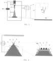
- FIG. 3 schematically illustrates a preparation and an operation environment of an electron source according to an embodiment of the present disclosure.
- a preparation and operation apparatus may comprise a vacuum chamber 111, a cooling head 107 (the cooling head 107 comprises a heating device, which is not shown), a sample holder 105, an electron source 101, a high voltage power source 115, a particle beam 113, a fluorescent screen assembly 103 and a gas introduction device 109, wherein the right figure is an enlarged schematic view of the dotted line frame in the left figure.
- the sample holder 105 may comprise a hairpin 120 for fixing the electron source 101, and the upper power source is the power source that heats the tip. This makes it possible to heat the electron source 101 and/or apply voltage to the electron source 101, and it is also possible to control the gas in the vacuum chamber, and the electron emission of the electron source can be observed through the fluorescent screen assembly 103.
- FIG. 4 schematically illustrates a process of preparing an electron source according to an embodiment of the present disclosure.
- the right figure is an enlarged schematic view of the image in the dotted line frame in the left figure, and the dotted line frame in the bottom of the left figure is schematic base.
- the gas molecules in the environment will gradually move toward the top of the tip, which is one of the reasons for the decline in the emission capability of the electron source of single-crystal tungsten in the prior art.
- a field (such as an electric field) is formed at the tip to make the gas molecules react with the metal atoms (white dots) on the surface of the tip to form a reaction product (black dots, i.e., the emission sites, abbreviated as Ma1).
- the black dots would be rooted in the surface of the tip, rather than dissociating on the surface of the tip.
- FIG. 5A schematically illustrates a high field strength structure on a base according to an embodiment of the present disclosure.
- At least one of the tips comprises a base and one or more high field strength structures on the base having a higher field strength than that of other portions of the base, wherein an outer surface of at least one of the high field strength structures comprises metal atoms.
- the number of the protrusions may be one, three, five, ten, etc., which is not limited herein.
- the material of the high field strength structure and the material of the base may be the same or different.
- a material of the metal atoms on surfaces of the base and/or the high field strength structure is the same as or different from a material of the high field strength structure, and if they are different, the metal atoms on the surfaces of the base and/or the high field strength structure may be formed by an evaporation process, an electroplating process or other methods, which is not limited herein.
- a material of the metal atoms on surfaces of the base and/or the high field strength structure is the same as or different from a material of the base, and if they are different, the metal atoms on the surfaces of the base and/or the high field strength structure may be formed by an evaporation process, an electroplating process or other methods, which is not limited herein.
- the material of the base, the material of the high field strength structure and the material of the body of the tip are the same or different, which is not limited herein. Accordingly, in the reaction with the gas molecules under a vacuum condition, the metal atoms on at least a portion of the surface of the protrusion have the same or larger reaction activity than that of other portions of the surface of the base.
- the high field strength structure may comprise a protrusion corresponding to the Lo1 position.
- the protrusion may have a size in an order of sub-nanometer to 100 nanometers. Due to the high field strength advantage at the protrusion, when a voltage is applied to the tip, at least a portion of the metal atoms on the surface of the protrusion will form a reaction product with the gas molecules under the action of the field strength. This makes it easy and quick to form an emission site at a designated position on the surface of the tip.
- the number of the emission sites on the surface of the protrusion can be adjusted by adjusting the size of the protrusion, the magnitude of the applied bias, the time length thereof or other parameters, for example, by increasing the time length of the applied bias or increasing the size of the protrusion, more emission sites may be formed to increase the emission current or the like.
- the protrusion is formed by any one or more of the following methods: heat treatment, application of electric field, thermal-field treatment, etching, and nano-machining or by a method of, for example, forming a protrusion by plating a layer of metal atoms on a single crystal metal tip followed by thermal annealing. It should be noted that the methods in which a protrusion may be formed on the surface of the tip are applicable, which is not limited herein.
- the base is made of an electrically conductive material having a melting point above 1000K
- the high field strength structure is made of an electrically conductive material having a melting point above 1000K
- a material of the metal atoms on surfaces of the base and/or the high field strength structure is a metal material having a melting point above 1000K.
- FIG. 5B schematically illustrates metal atoms on a surface of a high field strength structure according to an embodiment of the present disclosure.
- the materials of the base, the high field strength structure and the body of the tip may be metal materials or non-metal materials (for example, electrically conductive materials). If the electron source does not comprise a high field strength structure, it is only to be ensured that the surface of the base comprises metal atoms, and the base can introduce an electric current; if the electron source comprises a high field strength structure, it is only to be ensured that the surface of the high field strength structure comprises metal atoms, and the high field strength structure can introduce an electric current.
- the high field strength structure is located at a central position of the surface of the base; or, the high field strength structure is located on a base having a size greater than a given threshold, for example, a base having a larger size; or, the metal atoms are located at a central position of the top surface of the high field strength structure.
- a dimension of a beam angle of an electron beam may be adjusted by adjusting a size and shape of the base and/or the high field strength structure of the tip, the number of the emission sites may be adjusted by adjusting a size of the high field strength structure, a magnitude or a consistency of voltages at which the electron source emits current may be adjusted by adjusting a structure of the base and/or a structure of the high field strength structure, and a direction of an emission current may be adjusted by adjusting a shape of a top of the tip.
- the beam angle reduces; if the size of the base increases, then the beam angle reduces; if the field evaporation causes the height of the protrusion to decrease, then the beam angle reduces; the smaller the size of the protrusion is, the smaller the number of the emission sites under the same electric field is; etc.
- At least one of the tips comprises a base and one or more high field strength structures on the base having a higher field strength than that of other portions of the base, and an outer surface of at least one of the high field strength structures comprises metal atoms.
- the metal atoms on the surface of the high field strength structure are more likely to react with the gas molecules to form a reaction product in the same environment by virtue of the field strength advantage, so as to preferentially generate the emission site at the high field strength structure.
- FIG. 5C schematically illustrates an active region on a base according to an embodiment of the present disclosure.
- At least one of the tips comprises a base and one or more active regions on the base having larger reaction activity than that of other portions of the base, corresponding to the Lo2 position, wherein an outer surface of at least one of the active regions comprises metal atoms.
- the active region is shown in the shaded region of FIG. 5C .
- the number of the active regions may be 1, 3, 5, 10, etc., which is not limited herein, and the emission site may be preferentially formed in the active region located at the top region of the tip.
- the material of the base and the material of the body of the tip may be the same or different.
- the metal atoms in the active region may be formed by evaporation, electroplating or the like, for example, a certain area of metal atom layer is formed at the intersection of the axis of the tip and the surface by electroplating, the material of the metal atom layer has higher reaction activity with gas molecules, compared with the material of other surfaces of the base. Accordingly, the metal atoms on the surface of the active region of the base have larger reaction activity than that of other portions of the surface of the base in a reaction with gas molecules under a vacuum condition.
- the active region having the larger reaction activity is located at a central position of the surface of the base; or, the metal atoms are located at a central position of the surface of the base.
- At least one of the tips comprises a base and one or more active regions on the base having larger reaction activity than that of other portions of the base, and an outer surface of at least one of the active regions comprises metal atoms.
- the metal atoms on the surface of the active region are more likely to react with the gas molecules to form a reaction product in the same environment by virtue of the reaction activity advantage, so as to preferentially generate the emission site at the active region.
- FIG. 5D schematically illustrates an active region on a high field strength structure according to an embodiment of the present disclosure.
- At least one of the tips comprises a base and one or more high field strength structures on the base having a higher field strength than that of other portions of the base, at least a portion of surface of the high field strength structure is an active region having a larger reaction activity, corresponding to the Lo3 position, and an outer surface of the active regions comprises metal atoms.
- metal atoms on at least a portion of the surface of the protrusion have the same or larger reaction activity than that of other portions of the surface of the base in a reaction with gas molecules under a vacuum condition.
- the formation of the emission site on the designated region of the protrusion for example, an emission site is formed in the shaded region on the protrusion of FIG. 5D .
- the forming manner in which the metal atoms on the surface of the active region are formed may refer to the forming manner of the active region in the previous embodiment, which will not be described in detail herein.
- At least one of the tips comprises a base and one or more high field strength structures on the base having a higher field strength than that of other portions of the base, at least a portion of surface of the high field strength structure is an active region having a larger reaction activity, and an outer surface of the active region comprises metal atoms.
- the metal atoms on the surface of the active region are more likely to react with the gas molecules to form a reaction product in the same environment by virtue of the field strength advantage and the reaction activity advantage, so as to preferentially generate the emission site at the active region.
- FIG. 6 schematically illustrates an emission area having emission sites according to an embodiment of the present disclosure
- the tip having a protrusion is taken as an example.
- the top view of the emission sites can be referred to the right figure of FIG. 6 .
- the emission sites are not necessarily formed only in the region with the highest field strength.
- the apex position of the protrusion as shown in FIG. 6 has the strongest field strength, and the probability of forming the emission sites at the apex first is also greatest.
- the shape of the protrusion in FIG. 6 is hemispherical, alternatively, it may be square, polygonal, mesa shape, semi-elliptical, or other geometric structures, which are not limited herein.
- a disappearance temperature of the emission site is lower than a smallest value of disappearance temperatures of the base, the high field strength structure, and the metal atoms, and the disappearance temperature of the emission site is higher than an operating temperature of the electron source; or, a disappearance temperature of the emission site is lower than a smallest value of disappearance temperatures of the base, the high field strength structure, and the metal atoms, and the disappearance temperature of the emission site is higher than a larger value of an operating temperature of the electron source and a desorption temperature of the gas molecules adsorbed on any of the tips.
- the disappearance temperature of the emission site is higher than the desorption temperature of the gas molecules adsorbed on any of the tips, it facilitates the desorption of the gas molecules by heating, and facilitates improving the stability of the electron source by simple processing.
- the test environment for the electron source may be referred to FIG. 3 , and the background vacuum degree of the vacuum chamber 111 is less than or equal to 10 -3 Pa (generally less than 10 -6 Pa).
- An insulated sample holder 105 is plated on the cooling head 107, thereby a heating device (for example, a heating plate, a heating rod, etc. which is not shown here) may be plated on the sample holder, and the temperature may be adjusted between 10 and 500K.
- a pretreated tip for example, a tungsten single crystal tip, which may be a tip having a protrusion, the size of the protrusion being in an order of nm or sub-nm, or a tip having a region with a larger reaction activity
- a pretreated tip for example, a tungsten single crystal tip, which may be a tip having a protrusion, the size of the protrusion being in an order of nm or sub-nm, or a tip having a region with a larger reaction activity
- a voltage is applied to the tip, and the voltage may be a positive high voltage V P or a negative high voltage V N .
- the power source 115 may be a dual output high voltage power source with an output range of ⁇ 0 ⁇ 30kv.
- the gas introduction device 109 is used for introducing reaction gas molecules, for example, H 2 , or other reaction gases, for example, H-containing gas, like H 2 O, CH 4 , etc.
- the gas introduction amount may be dynamically adjusted.
- the vacuum degree is ⁇ 10 -4 Pa (it should be noted that the residual gas molecules in the chamber may be directly utilized, and the main component thereof is hydrogen gas).
- the fluorescent screen assembly 103 is used to convert a particle beam image into a light image.
- the signal When the signal is small, the signal may be amplified by using a fluorescent screen-multichannel plate assembly.
- a voltage is applied to the tip, the particle beam may be extracted.
- the applied voltage may be a positive voltage or a negative voltage.
- the positive voltage When the positive voltage is applied, a positive ion beam is output in a case where there is imaging gas; when the negative voltage is applied, an electron beam is output.
- FIG. 7 schematically illustrates a formation process of emission sites according to an embodiment of the present disclosure.
- the emission site Ma1 is formed by the reaction of gas molecules and metal atoms on the surface under the action of a strong electric field, and the emission site Mal is formed at a certain temperature.
- the formation process of the emission site is based on an in-depth study of a hydrogen adsorption behavior in a small region of the surface of the tip.
- a tip of a (111) oriented single-crystal tungsten is provided, and a protrusion is formed on the tip by the method as described above, for example, the tip undergoes a flashing process (heating to 1200K for 3s, and applying a bias voltage in the process, etc.).
- a nano-scale protrusion may be formed at a central position of the surface of the tip, and the surface thereof is clean.
- FIG. 7a when a negative voltage of up to -2KV is applied to the tip, a field electron emission mode is formed.
- the formation temperature of the emission site Ma1 is ⁇ 50K.
- the emission current (I E ) is always controlled within 5nA and the vacuum degree is 10 -7 Pa.
- the gas adsorption first causes a decrease in the emission capability, the emission pattern on the fluorescent screen of assembly 103 is gradually becoming dark, and the emission current is gradually decreased, that is, the emission capability of the existing tungsten cleaning surface is gradually decreased.
- the emission pattern disappears almost completely over time, and at this time, the emission capability of the conventional tungsten cleaning surface almost completely disappears.
- the emission site of the present disclosure begins to form, and the composition of this emission site is different from that of the previous emission substance.
- the previous emission substance is tungsten atoms of single-crystal tungsten
- this emission site is a reaction product of tungsten atoms on the surface of the tip with gas molecules, for example, a reaction product of tungsten atoms with hydrogen molecules. This reaction product is fixed on the surface of the tip.
- the emission site eventually becomes brighter.
- the emission site with high emission capability is finally formed, and the emission current is further increased.
- FIG. 7a By comparing FIG. 7a with FIG. 71, it can be clearly seen that the emission capability of the emission site is obviously improved, and the emission sites are more concentrated at the central protrusion position.
- the current is always controlled to be very small, and the fluorescent screen is far away from the tip, and the vacuum degree is good, the influence of ion bombardment may be excluded.
- the addition of a positive high voltage can form a substance having the same field emission characteristic. At this time, there is no emission current at all, indicating that the dissociative atomic-scale particles caused by the ion bombardment do not participate in the formation process of the emission site Ma1.
- the gas for example, H 2
- the metal atoms on the surface to form a certain H-W reaction product (compound), which belongs to a kind of Mal. It seems that this kind of compound is directly bonded to the surface and does not move. Similar substances can be formed at other positions, but they do not move and are always stable emission sites.
- the emission capability of a single emission site can reach more than 30uA. If a dense emission region is formed and the emission patterns are connected into one piece, then the total current can reach an order of 100uA. If the emission area is increased (the number of the emission sites is increased), the emission current in an order of 10mA can be achieved, significantly exceeding the stable emission capability of the existing CFE ( ⁇ 10 microamperes). Recently, Keigo Kasuya et al. reached an extreme emission current of about 3000 microamperes by strengthening the vacuum degree of the chamber to 4 ⁇ 10 -10 Pa, however, this vacuum degree is difficult to achieve.
- Different emission capacities are achieved at different vacuum degrees.
- a high emission current can be maintained at a high vacuum degree, and the maximum emission current is rapidly damped at a low vacuum degree.
- FIG. 8 schematically illustrates a formation process of emission sites according to another embodiment of the present disclosure. As can be seen from the figure, the formed emission region is small and concentrated.
- the tip terminated by the emission site has field emission consistency, that is, the voltage of the emission current is consistent, for example, when the emission current is 1 microamperes, the voltage is -1.2 ⁇ 0.1 KV.
- the structure of the electron source does not change during operation, the applied voltage value does not change, and the stable voltage value makes the design of for example the electron gun simpler.
- the magnitude and consistency of the voltage of the emission current of the electron source are adjusted by adjusting the structure of the base and/or the high field strength structure, for example, for the emission site formed on the protrusion which is formed on the tip by field etching, field evaporation, etc., when the emission current is 1 microampere, the voltage may be lower than -0.5KV (for example, the extraction voltage is -0.4KV), which makes the design of the electron gun structure simpler.
- the electron source has good stability, the emission site (referring to the solid black balls in FIG. 4 ) can be stably rooted at a specific position on the surface of the tip, the plurality of emission sites can give a total current of mA order at most, it can operate under poor vacuum degree (10 -5 Pa), and it is easy to store.
- the tip includes a base and a protrusion of nm order on the base, the size of the protrusion is of nm or sub-nm order.
- the emission site is formed on the surface of the protrusion.
- the formation process of the emission site Ma1 is as follows: under a strong electric field (for example, in the range of 1 ⁇ 50V/nm, it should be noted that the electric field is affected by the voltage polarity and material properties), the gas molecules directly react with the metal atoms on the surface of the tip to form a gas-metal compound, the H-W compound will be described below. At a higher vacuum degree, the main residual gas molecules are H 2 . Since the electric field on the surface of the protrusion is the strongest, it is preferentially formed here.
- the emission site Mal is a reaction product that is rooted on the surface of the tip and formed by the reaction of the gas molecules with the metal atoms on the surface of the tip.
- the positions of these emission sites are fixed and do not move, but a single emission site Mal may flicker at different emission currents.
- the emission site Ma1 has a surface protection function: the emission site Ma1 is formed by the reaction of the metal atoms at the outermost surface with the gas molecules, that is, it is a reaction product, therefore it is difficult for it to interact with the surrounding gas molecules, for example, adsorb the gas molecules, etc. Even the gas is adsorbed, it is difficult to influence the emission site Ma1 on the surface of the tip, i.e., continue the chemical reaction immediately.
- the adsorbed gas on the emission site Ma1 can be effectively desorbed by means of low temperature heating treatment ( ⁇ 1000K), and the presence of the emission site Ma1 can be maintained.
- the heating treatment removes the emission site Ma1 partially and the portion of the metal atoms is exposed, the emission site Ma1 can be further formed there during operation (in a case of the presence of the electric field E). Therefore, it is equivalent to an addition of protective layer to the tip, effectively blocking the reaction of the gas with the tip under a strong field. While for other surfaces where the emission site Ma1 is not formed, due to the weak local electric field, the emission capability is weak, the contrast may be neglected. This greatly improves the operation stability and prolongs the stability period of the electron source.
- the emission site Ma1 has strong environmental adaptability and can work in a vacuum of 10 -5 Pa. If it is supplied with low temperature, it can work in a vacuum of 10 -3 Pa.
- Different emission current ranges can be selected under different vacuum conditions to be used according to specific needs.
- the magnitude of the emission current can be directly controlled by the extraction voltage, and the output of pulse current (by applying pulse voltage) and constant current ((by applying constant voltage) can be realized.
- the emission area for example, the area of the emission region on the upper surface of the protrusion, the emission area can be controlled and changed by for example adjusting the diameter of the protrusion on the head of the tip.
- the emission area can reach atomic level or 10 nm level.
- the size of the emission area can be controlled by changing the area of the active region.
- the formation location (Lo) of the emission site Ma1 may be preselected by for example the following method: an electric field dominating region Lo1 is formed on the surface of the tip (referring to FIG. 5A , for example, an nm-level protrusion is formed) so that the electric field there is higher than other regions of the tip; or, an active region Lo2 is formed on the surface of the tip, and the region has greater reaction activity with the gas (referring to FIG. 5C , compared to other regions); or a region Lo3 (referring to FIG. 5D ) having the above two features is formed.
- the protrusion may be formed by heat treatment, thermal-field treatment, etching, nano-processing, etc.; and the active atomic region may be formed by various atomic evaporation methods.
- the size of the emission area can also be controlled by the above means, and its scale is of nm or atomic order.
- Lo1 is located above a larger base of the tip.
- the magnitude of the beam angle of the electron beam can be adjusted by controlling the sizes of the base of the tip and the protrusion.
- the tip has a geometry with a protrusion at the center.
- the electric field strength at the surrounding region of the tip is weaker than the electric field strength at the center of the surface of the tip.
- At least one layer or more layers at the outermost surface of the tip are made of metal atoms, which according to the invention are of tungsten.
- the material of the body of the tip may be metal, or other electrically conductive materials, such as metal-hexaboride or the like, preferably having a higher melting point (e.g., >1000 K).
- Tip condition Taking a tip having a protrusion as an example, a nano-scale protrusion is formed on a region of the surface of the tip where the above substance (emission site) is needed to be formed, so that a strong surface electric field E s is generated on the surface of the protrusion when a bias voltage (Vs) is applied to the tip, where Es is greater than the electric field at its periphery.
- Vs bias voltage
- the surface electric field of the protrusion on the tip is Es, which is in an order of ⁇ 1V/nm.
- the Es (or V S ) may be positive, and its strength needs to ensure that the atoms on the surface of the tip do not evaporate; in addition, the Es (or Vs) may also be negative, and it is necessary to ensure that the emission does not cause the tip to be burned out due to overcurrent.
- Gas molecules The main component is H 2 , or H-containing gas molecules. It may be realized by introducing external gas molecules, or it may be realized by directly utilizing the residual gas molecules in the vacuum.
- the temperature should be less than the decomposition temperature of the emission site Mal. According to observation, it should be less than 1000K.
- the reaction temperature is below a low temperature 150K.
- the operating temperature is between 500 and 800K.
- the temperature needs to be satisfied in such a way that the surface topography of the tip is not altered, for example, it should be below the deformation temperature of the top of the tip.
- Removal manner of the formed emission site If the emission capability of the formed emission site is degraded, the degraded emission site may be removed.
- the emission site on the surface may be removed by field evaporation, i.e., adding a positive high voltage. It is also possible to directly remove the emission site Mal by directly heating to more than 1000K. After the removal, the emission site Mal may be formed again in situ.
- the emission site of the electron source is a reaction product of metal atoms fixed on the surface of the tip with gas molecules, rather than gas molecules, dissociative particles or the like that are dissociative on the surface of the tip, it would not incur over-current burnout due to that the dissociative emission sites gather together to form a new emission site, thereby effectively improving stability.
- the emission site comprises the reaction product, in comparison with metal atoms or other metal compounds (such as metal boride or the like), it has better stability in the working environment (with the presence of gas molecules), for example, being less likely to react with hydrogen in the working environment, further improving the stability of the electron source.
- the emission site of the electron source may be a reaction product of a single metal atom with gas molecules, that is, the emission site is composed of only one or several atoms, therefore an atomic-scale electron source having a low work function may be formed.
- the emission site is a reaction product of the gas molecules with the metal atoms on the surface of the tip, it is rooted in the surface of the tip, it is relatively less susceptible to ion bombardment, and less susceptible to the gas in the environment.
- the field emission current may be increased by increasing the number of the emission sites.
- the electron source provided by the present disclosure has the advantages of stability, large field emission current, operation at a relatively poor vacuum degree, easy storage, and so on.
- an electron gun comprising: the electron source as described above, a cooling device, a heating device and a gas introduction device.
- the electron source is configured for emitting electrons
- the cooling device is configured for dissipating heat for the electron source
- the electron source is fixed to the cooling device by an electrically insulating heat conductor
- the heating device is configured for heating the electron source to adjust a temperature of the electron source
- the gas introduction device is configured for introducing a hydrogen-containing gas. Since the formation temperature and the operating temperature of the emission site on the electron source surface of the electron gun are lower, the structure of the electron source does not change during operation, the applied voltage value does not change, the voltage value is more stable so that the design of the electron gun is simpler.
Description
- The present disclosure relates to the field of electron source technology, and in particular, to a field emission electron source and a field emission electron gun.
- Free electrons in metal may be emitted under certain conditions. If a cathode is made of metal and made into a very fine tip and it is applied by a voltage of thousands of volts in a vacuum, then the electrons in the metal may be emitted from the cathode cold metal. This method of emitting electrons is called as field emission, belonging to cold cathode emission.
- For the electron source, the most important parameter is brightness, which directly determines the beam quality. At an extraction voltage of V0, the brightness may be denoted in formula (1):

- Where B refers to the brightness, I refers to an emission current, S refers to an equivalent emission area, d refers to an equivalent diameter, Ω refers to a solid angle, and α refers to an half opening angle. Further, the brightness B is proportional to an acceleration voltage Va, as shown in the formula (2).

- As can be seen from the formula (1), in order to obtain a high brightness, it is necessary to increase I and reduce α and d as much as possible. Moreover, the lower the extraction voltage V0 is required to obtain a certain emission current, the better it is, which requires that an emission surface of the tip has a lower work function and a sharper head structure. In addition, another key parameter of the electron source is monochromaticity, which can be expressed by an energy spread δE.
- Based on the above, the most ideal electron source is the cold field emission electron source (abbreviated as CFE). The brightness of CFE is higher than that of other types of electron sources by about one order of magnitude, and it has a small energy spread (~0.3eV). In addition, in order to seek for the extreme diameter as far as possible, atomic-scale electron sources having a low work function recently have become the research hotspots, that is, the emission site consists of only one or several atoms.
In the process of implementing the concept of the present disclosure, the inventors have found that the CFE in the prior art has at least the following disadvantages: firstly, the stability of the CFE is often poor, and it is required to work under extremely high vacuum (10-9~10-8 Pa), which severely limits the scope of application thereof. Even in such an environment, it needs to be processed regularly to obtain a more stable working state. Secondly, due to the impact of ion bombardment, the CFE is easier to be burned out. Thirdly, the aforementioned disadvantages become more serious at a larger emission current, the current CFE generally needs a total emission current of ~10 microamperes for stable operation for a long time, and the utilization rate thereof is very low. In view of the aforementioned drawbacks, the Schottky thermal-field emission source is dominant in the field of high-brightness electron sources. - In view of the above, the present disclosure provides a stable electron source and electron gun which have a large field emission current and can operate at a relatively poor vacuum degree.
- According to an aspect of the present disclosure, there is provided an electron source as defined in
claim 1, comprising one or more tips, wherein at least one of the tips comprises one or more fixed emission sites, wherein the emission sites comprises a reaction product of metal atoms on a surface of the tip with gas molecules. A metal atom material comprises tungsten and the gas molecules comprise hydrogen-containing gas molecules. - Since the emission site is a reaction product of metal atoms fixed on the surface of the tip with gas molecules, it is rooted in the surface of the tip, rather than gas molecules, dissociative particles or the like that are dissociative on the surface of the tip. It would not incur over-current burnout due to that the dissociative emission sites gather together to form a new emission site, thereby effectively improving stability. Moreover, the emission site comprises the reaction product of the metal atoms on the surface of the tip with the gas molecules, in comparison with metal atoms or other metal compounds (such as metal boride or the like), it has higher stability in the working environment (with the presence of gas molecules), for example, being less likely to interact or react with, for example, hydrogen in the working environment, further improving the stability of the electron source. In addition, the emission site of the electron source provided by the present disclosure may be a reaction product of one or several metal atoms with gas molecules, that is, an atomic-scale electron source having a low work function may be formed. Further, the reaction product significantly reduces the surface work function, and the formation of the pointed cone of the surface emission site also significantly increases the emission capability. Still further, the current value of the field emission current may be increased by increasing the number of the emission sites. In this way, it is possible to form a stable electron source with a large field emission current.
- According to an embodiment of the present disclosure, the emission sites comprise a reaction product of the metal atoms with the gas molecules under an electric field. This facilitates the formation of the emission site at a designated position of the tip, particularly at a position where it has an electric field advantage, for example, at a protrusion of the tip.
- According to an embodiment of the present disclosure, in a specific example, at least one of the tips comprises a base and one or more high field strength structures on the base having a higher field strength than that of other portions of the base, and an outer surface of at least one of the high field strength structures comprises metal atoms. The metal atoms on the surface of the high field strength structure are more likely to react with the gas molecules to form a reaction product in the same environment by virtue of the field strength advantage, so as to preferentially generate the emission site on the high field strength structure. In another specific example, at least one of the tips comprises a base and one or more active regions on the base having a larger reaction activity than that of other portions of the base, and an outer surface of at least one of the active regions comprises metal atoms. The metal atoms on the surface of the active region are more likely to react with the gas molecules to form a reaction product in the same environment by virtue of the activity advantage, so as to preferentially generate the emission site at the active region. In still another specific example, at least one of the tips comprises a base and one or more high field strength structures on the base having a higher field strength than that of other portions of the base, at least a portion of surfaces of the high field strength structures are active regions having a larger reaction activity, and outer surfaces of the active regions comprise metal atoms. The metal atoms on the surface of the active region are more likely to react with the gas molecules to form a reaction product in the same environment by virtue of the field strength advantage and the activity advantage, so as to preferentially generate the emission site at the active region.
- According to an embodiment of the present disclosure, the electric field is generated by applying a positive bias, a negative bias, or a combination of a positive bias and a negative bias; for applying a positive bias, a strength of the electric field comprises 1 to 50 V/nm; for applying a negative bias, a strength of the electric field comprises 1 to 30 V/nm. This can avoid the atoms on the surface of the tip from evaporating, and can avoid the tip from being burnt out due to overcurrent during the formation of the emission site.
- According to an embodiment of the present disclosure, the high field strength structure comprises a protrusion.
- According to an embodiment of the present disclosure, the protrusion has a size in an order of sub-nanometers to 100 nanometers.
- According to an embodiment of the present disclosure, the protrusion is formed by any one or more of the following methods: thermal annealing, application of electric field, thermal-field treatment, etching, and nano-machining or by a method of, for example, forming a protrusion by plating a layer of metal atoms on a single crystal metal tip followed by thermal annealing.
- According to an embodiment of the present disclosure, for a tip comprising a protrusion, metal atoms on at least a portion of a surface of the protrusion have the same or larger reaction activity than that of other portions of the surface of the base in a reaction with gas molecules under a vacuum condition, that is, at least a portion of the surface of the protrusion (such as a designated region) has metal atoms having a larger reaction activity than other regions. For a tip comprising no protrusion, metal atoms on a surface of the active region of the base have larger reaction activity than that of other portions of the surface of the base in a reaction with gas molecules under a vacuum condition.
- According to an embodiment of the present disclosure, the base is made of an electrically conductive material; and/or, the high field strength structure is made of an electrically conductive material; and/or, the base and/or the high field strength structure has metal atoms on surfaces thereof; and/or, the high field strength structure is made of a same or different material from the base; and/or, a material of the metal atoms on surfaces of the base and/or the high field strength structure is the same as or different from a material of the high field strength structure, and if they are different from each other, the metal atoms on the surfaces of the base and/or the high field strength structure are formed by an evaporation process or an electroplating process; and/or, a material of the metal atoms on surfaces of the base and/or the high field strength structure is the same as or different from a material of the base, and if they are different, the metal atoms on the surfaces of the base and/or the high field strength structure are formed by an evaporation process or an electroplating process.
- According to an embodiment of the present disclosure, the hydrogen-containing gas molecules are introduced gas molecules and/or gas molecules remaining in a vacuum environment.
- According to an embodiment of the present disclosure, the hydrogen-containing gas molecules comprise hydrogen gas.
- According to an embodiment of the present disclosure, a disappearance temperature of the emission site is lower than a smallest value of disappearance temperatures of the base, the high field strength structure, and the metal atoms, and the disappearance temperature of the emission site is higher than an operating temperature of the electron source; or, a disappearance temperature of the emission site is lower than a smallest value of disappearance temperatures of the base, the high field strength structure, and the metal atoms, and the disappearance temperature of the emission site is higher than a larger value of an operating temperature of the electron source and a desorption temperature of the gas molecules adsorbed on any of the tips. In this way, it facilitates desorption, repair, and the like by heat treatment, to prolong the working life.
- According to an embodiment of the present disclosure, the base is made of an electrically conductive material having a melting point above 1000K; and/or, the high field strength structure is made of an electrically conductive material having a melting point above 1000K; and/or, a material of the metal atoms on surfaces of the base and/or the high field strength structure is a metal material having a melting point above 1000K; and the reaction product of the metal atoms with the gas molecules comprises a reaction product of metal atoms having a melting point above 1000K with gas molecules under a vacuum condition. The tip preferably adopts an electrically conductive material having a melting point above 1000K, which is more stable and facilitates cleaning of the tip by the heat treatment method or the like, as described above.
- According to an embodiment of the present disclosure, the metal material is tungsten; and the emission site comprises a hydrogen tungsten compound.
- According to an embodiment of the present disclosure, a dimension of an opening angle of an electron beam is adjusted by adjusting a size and shape of the base and/or the high field strength structure of the tip; and/or, the number of the emission sites is adjusted by adjusting a size of the high field strength structure; and/or, a magnitude or a consistency of voltages at which the electron source emits current is adjusted by adjusting a structure of the base and/or a structure of the high field strength structure; and/or, a direction of an emission current is adjusted by adjusting a shape of a top of the tip. Herein, the extraction voltage may be lower than -0.5KV, for example, the extraction voltage is -0.4KV.
- According to an embodiment of the present disclosure, the high field strength structure or the active region having the larger reaction activity is located at a central position of a surface of the base; and/or, the high field strength structure is located on a base having a size greater than a given threshold; and/or, the metal atoms are located at a top of the high field strength structure or at a central position of a surface of the base.
- According to an embodiment of the present disclosure, an operation condition of the tip comprises: in a case where a temperature of the tip is less than or equal to 1000K, an operation pressure is less than or equal to 10-3Pa; or, in a case where a temperature of the tip is greater than or equal to 500K, and less than or equal to 800K, an operation pressure is less than or equal to 10-6Pa; or, in a case where a temperature of the tip is less than or equal to 150K, an operation pressure is less than or equal to 10-6Pa. Since the formation temperature and the operating temperature of the emission site are lower, the structure of the electron source does not change, the structure of the electron source does not change during operation, and the applied voltage value does not change.
- According to an embodiment of the present disclosure, a size of the emission site is in an order of nanometer or sub-nanometer, that is, the size of the emission site may be less than the size of the protrusion; and a value of an emission current of the emission site of the tip is up to an order of 10 mA by means of adjusting an operation voltage.
- According to an embodiment of the present disclosure, the electron source has a cold field emission characteristic, and a magnitude of an emission current is adjusted by adjusting an extraction voltage.
- According to another aspect of the present disclosure, there is provided an electron gun, comprising: the electron source as described above for emitting electrons, a cooling device, a heating device and a gas introduction device. The cooling device is configured for dissipating heat for the electron source, the electron source is fixed to the cooling device by an electrically insulating heat conductor, the heating device is configured for heating the electron source to adjust a temperature of the electron source, and the gas introduction device is configured for introducing a hydrogen-containing gas. Since the formation temperature and the operating temperature of the emission site are lower, the structure of the electron source does not change during operation, the applied voltage value does not change, and the voltage value is stable, all these make the design of the electron gun simpler.
- According to an embodiment of the present disclosure, at least one emission site may be further removed from the electron source by the following operations: after one or more fixed emission sites are formed on at least one of the tips, gas molecules are adsorbed on the emission site by applying an electric field, then the emission capability of the tip will be lowered or even disappear, so as to remove at least one emission site.
- The above objects, features and advantages and others of the present disclosure will become more apparent by means of the description of the embodiments of the present disclosure below with reference to the accompanying drawings. In the drawings:
-
FIG. 1 schematically illustrates a typical field emission behavior of an electron source of a (310) oriented single-crystal tungsten emitter in the prior art; -
FIG. 2 schematically illustrates an electron source according to an embodiment of the present disclosure; -
FIG. 3 schematically illustrates a preparation and an operation environment of an electron source according to an embodiment of the present disclosure; -
FIG. 4 schematically illustrates a process of preparing an electron source according to an embodiment of the present disclosure; -
FIG. 5A schematically illustrates a high field strength structure on a base according to an embodiment of the present disclosure; -
FIG. 5B schematically illustrates metal atoms on a surface of a high field strength structure according to an embodiment of the present disclosure; -
FIG. 5C schematically illustrates an active region on a base according to an embodiment of the present disclosure; -
FIG. 5D schematically illustrates an active region on a high field strength structure according to an embodiment of the present disclosure; -
FIG. 6 schematically illustrates an emission area having emission sites according to an embodiment of the present disclosure; -
FIG. 7 schematically illustrates a formation process of emission sites according to an embodiment of the present disclosure; and -
FIG. 8 schematically illustrates a formation process of emission sites according to another embodiment of the present disclosure. - Hereinafter, the embodiments of the present disclosure will be described with reference to the accompanying drawings. However, it should be understood that the description is only exemplary, and is not intended to limit the scope of the present disclosure. In the following detailed description, numerous specific details are set forth for facilitating the explanation to provide a thorough understanding of the embodiments of the present disclosure. However, it is apparent that one or more embodiments may be practiced without these specific details. In addition, the description of well-known structures and techniques is omitted in the specification in order to avoid unnecessarily misunderstanding the concept of the present disclosure.
- The terms used herein are merely for the purpose of describing the particular embodiments, rather than limiting the present disclosure. The terms "comprise", "include" and the like used herein indicate the presence of the described feature, step, operation and/or component, but rather excluding the presence or addition of one or more features, steps, operations and/or components.
- All the terms (comprising technical and scientific terms) used herein have the meanings commonly understood by those skilled in the art, unless otherwise defined. It should be noted that the terms used herein are to be interpreted as having meanings consistent with the context of the present specification and should not be interpreted in an ideal or too inflexible manner.
- In a case where an expression like "at least one of A, B and C, etc." is used, it should generally be interpreted according to the meaning of the expression as commonly understood by those skilled in the art (for example, "a structure having at least one of A, B, and C" shall comprise, but is not limited to, a structure having A alone, B alone, C alone, A and B, A and C, B and C, and/or A, B, and C). In a case where an expression like "at least one of A, B, or C, etc." is used, it should generally be interpreted according to the meaning of the expression as commonly understood by those skilled in the art (for example, "a structure having at least one of A, B, and C" shall comprise, but is not limited to, a structure having A alone, B alone, C alone, A and B, A and C, B and C, and/or A, B, and C). It should also be appreciated by those skilled in the art that transitional conjunctions and/or phrases that are arbitrarily representing two or more optional items, whether in the specification, claims, or drawings, are to be construed as the possibility of one of the items, either or both of these items. For example, the phrase "A or B" should be understood as including the possibility of "A" or "B", or "A and B".
- The field emission behavior in the prior art will be firstly described below in order to better understand the technical solutions of the present disclosure.
-
FIG. 1 schematically illustrates a typical field emission behavior of an electron source of a (310) oriented single-crystal tungsten emitter in the prior art. - As shown in
FIG. 1 , the existing electron source, for example, the electron source of a (310) oriented single-crystal tungsten, undergoes the following three stages during use. Firstly, the clean electron source enters a stability period (Stability) in company with the adsorption of gas. However, with the further adsorption of gas, noise of the current gradually appears, entering an instability period (Instability). Then, the stability of the electron source is deteriorated, and flashing process is required (heating to about 2000 °C in a short time) to return to the steady state. If it is not flashing processed in time, contamination would gradually appear on the surface, and the emission current would start to fluctuate drastically, eventually leading to burnout. - Regarding the above burnout, the inventors' further studies have shown that it is closely related to ion bombardment. This is due to the fact that the gas molecules in the surrounding space of the tip will be ionized after the electrons are emitted, and then bombard the tip. One possibility is that the surface of the tip is bombarded to form a plurality of protrusions, and the plurality of protrusions respectively serve as emission sites, and it finally causes excessive current, resulting in the burnout. There is also a mechanism in which the gas molecules adsorbed to the surface of the tip or a combination thereof with other substances are continuously moved under an electric field, and finally gathered into a nano-scale protrusion as an emission site on a defect point on a surface (for example, a defect point generated by ion bombardment), and the rapid growth of the emission site causes an overcurrent, which eventually leads to the burnout of the tip.
- Further, the aforementioned problems become more serious at a larger emission current. Generally, the total emission current for stable operation for a long time is ~10 microamperes, and the utilization rate is very low. In view of the aforementioned drawbacks, the Schottky thermal-field emission source is dominant in the field of high-brightness electron sources.
- Essentially, for the CFE, no material can avoid the effects of gas adsorption and ion bombardment. However, if the operation is under high current (>10 microamperes), the electron excitation degassing (especially taking place at the extraction electrode with electron bombardment) will further degrade the vacuum degree, which results in poor emission stability of the tip, and extremely large fluctuation range, thereby failing to operate stably for a long time. Therefore, how to provide a stable and large field emission current has been one of the most important challenges in the development of cold field emission electron sources.
- In order to avoid the above effects of gas adsorption and ion bombardment, the current field emission electron source (generally referring to a metal tip) can only work in ultra-high vacuum (<10-8 Pa), which seriously restricts the application range of the CFE. Further intensive research relating to this has been carried out by the inventors, and the following characteristics are found. The components of the residual gas in the vacuum comprise H2, CO, and CO2, but the main component is H2. The adsorption of H2 causes the emission capability of the clean surface to gradually deteriorate. It can be concluded that in this vacuum range, the influence of H2 fundamentally determines the field emission performance of the tip. Therefore, how to deal with the influence of H2 becomes the key to achieve a high stability of tip. There are also some technical solutions in the prior art that can alleviate the problem of gas adsorption. For example, Keigo Kasuya et al. invented a technique (mild flashings at 700 °C) by further increasing a vacuum degree of a chamber to an order of 1×10⁻⁹ Pa, and this technique allows the W (310) surface to be always in a cleaner emission state, extending its operation time and achieving high emission capability. The technical solution of this patent has been widely used in Hitachi's electron microscope products.
- In addition, there are some technical solutions in which some dissociative particles (atomic clusters) on the surface of the tip are used as the emission sites, which is also a solution way to be attempted. These dissociative substances may be contaminants formed by prolonged placement of the tip under poor vacuum degree, and the action of the electric field allows these dissociative substances to move somewhere on the tip. These emission sites have a very small beam angle (~5°), the extraction voltage is extremely low, and the brightness can reach more than 10 times that of the conventional W (310). Although it is not possible to form a large emission current (generally steadily giving the current of ~10nA), it exhibits excellent stability (<1×10⁻⁷ Pa). One possible inference is that the very small beam angle and emission area can effectively reduce the effects of ion bombardment. However, as mentioned above, this kind of dissociative substances is not fixed, and the inventors have found that when the current is large (> 1 uA), the electron source is easily burned out, and in the operation process, such substances continuously appear, its emission state is gradually changed, and it is difficult to maintain it for a long time. Another problem is that when it is exposed to the atmosphere, it is highly susceptible to the interference of the gas since the size of the substance is comparable with the gas molecules.
- Based on the above various analyses, inferences, and experiments, the inventors provide an electron source according to the present disclosure, it can achieve a long-term stable operation thereof, it can provide a large field emission current, can work in a poor vacuum environment, and it is also less susceptible to the interference of the gas even it is exposed to the atmosphere.
- An embodiment of the present disclosure provides an electron source as defined in
claim 1, comprising one or more tips, wherein at least one of the tips comprises one or more fixed emission sites, the emission sites comprise a reaction product of metal atoms on a surface of the tip with gas molecules. The metal atoms on the surface of the tip are fixed on the surface of the tip, the reaction product formed thereby with the gas molecules is rooted on the surface of the tip, and the reaction product is a reaction product formed by the reaction of the metal atoms with the gas molecules under a condition approximate to the operation condition, the reaction product has less reaction activity to react with the gas molecules again, therefore it has a high stability. Further, since the amount of the reaction product can be controlled, it is possible to provide a large field emission current by increasing the amount of the reaction product. In addition, since the reaction product is a reaction product formed by the reaction of the metal atoms with the gas molecules, it is less susceptible to the interference of the gas even it is exposed to the atmosphere. -
FIG. 2 schematically illustrates an electron source according to an embodiment of the present disclosure. - As shown in
FIG. 2 , the electron source may comprise one or more tips. For convenience of description, one tip is taken as an example to describe all the embodiments. - The tip may comprise one or more emission sites that are fixed to the surface of the tip, and the emission sites may be a reaction product of metal atoms on the surface of the tip with gas molecules.
- In one embodiment, the reaction product of the metal atoms on the surface of the tip with the gas molecules under an electric field may be implemented by various implementations, for example, applying a voltage directly to the tip to form a higher field strength on the surface of the tip, to promote the reaction of the metal atoms on the surface of the tip with the gas molecules to form the reaction product; or applying a voltage to a field strength generating structure (for example, an electrode or the like) near the tip to form an electric field, thereby forming a higher field strength on the surface of the tip, to promote the reaction of the metal atoms on the surface of the tip with the gas molecules to form the reaction product. In short, the field formed on the surface of the tip and the manner in which the field is formed are not limited herein, as long as it is possible to form a field (for example, an electric field) on the surface of the tip, which is capable of promoting the metal atoms on the surface of the tip to react with the surrounding gas molecules to form a reaction product.
- In the embodiment in which the field is formed by applying a voltage to the tip, in an exemplary example, the electric field is generated by applying a positive bias, a negative bias, or a combination of a positive bias and a negative bias to the tip. If a positive bias is applied, the strength of the electric field comprises 1 to 50 V/nm; if a negative bias is applied, the strength of the electric field comprises 1 to 30 V/nm.
- The emission site may be formed at a designated position of the tip, for example, within a certain range of a position where the tip axis intersects the surface of the tip. Alternatively, the emission site may also be formed on a specific structure, such as a protrusion or other structures having a field strength advantage to preferentially form the reaction product of the metal atoms with the gas molecules. The emission site may also be formed at a specific region having reaction activity, such as a specific metal atom region where they are more likely to react with the gas molecules. Of course, a combination of the above two cases may be used. They are not limited herein.
- The metal atoms may be metal atoms on the surface of the body of the tip, that is, the type of the metal atoms is the same as the type of the body of the tip, and they may also be a different kind of metal atoms formed on the surface of the tip by evaporation, electroplating or the like. According to the invention, the metal atom material comprises tungsten. But without forming part of the claimed invention, other materials may be considered: The metal atoms may adopt another metal material having a melting point higher than 1000K, which is more stable and facilitates cleaning of the tip by the heat treatment method or the like, as described above. For example, the metal material having a melting point higher than 1000K may comprise any one or more of the following: iridium, tantalum, molybdenum, niobium, hafnium chromium, vanadium, zirconium, titanium, rhenium, palladium, platinum, rhodium, osmium, ruthenium, gold, and metal-hexaboride. For example, a certain kind of metal atoms alone acts as the metal atoms on the surface of the tip, or a laminate formed of several kinds of metal atoms, for example, a laminate of a titanium layer, a platinum layer, and a tungsten layer, or a non-monoplasmatic metal layer formed by mixing several kinds of metal atoms, act as the metal atoms, which is not limited herein.
- The gas molecules may be introduced by a gas introduction device, for example, they are specific gas molecules introduced through a gas flow valve or the like, or may be gas molecules remaining in the vacuum chamber . Of course, a combination of the above two cases may be used. They are not limited herein. The gas molecules comprise hydrogen-containing gas molecules. The above gas molecules may be the introduced gas molecules, and therefore the gas introduction amount can be dynamically adjusted. Generally, when introduced, the vacuum degree is <10-4 Pa. When the residual gas in the vacuum chamber is directly utilized, the main residual gas in the vacuum chamber is hydrogen gas. Preferably, the hydrogen-containing gas molecules comprise hydrogen gas.
- It should be noted that the temperature at which the emission site disappears, such as the decomposition temperature, may be lower than the temperature at which the body of the tip disappears in order to remove the emission site, and the disappearance temperature of the emission site may be higher than the operating temperature and the temperature at which the adsorbed gas molecules are desorbed, such that it is convenient to carry out desorption by a simple heat treatment (for example, flashing or other heat treatments) to restore the electron source to a stable state.
- Due to its structural characteristics, the electron source provided by the present disclosure has a low extraction voltage of the emission site, a fixed and non-dissociative emission site, a long operation life, and can operate under a poor vacuum degree. Since the formation temperature and the operating temperature of the emission site are lower, the structure of the electron source does not change during operation, and the applied voltage value is stable and does not change. For example, it can operate under the following operation conditions, for example, in a case where a temperature of the tip is less than or equal to 1000K, an operation pressure is less than or equal to 10-3Pa; or, in a case where a temperature of the tip is greater than or equal to 500K, and less than or equal to 800K, an operation pressure is less than or equal to 10-6Pa; or, in a case where a temperature of the tip is less than or equal to 150K, an operation pressure is less than or equal to 10-6Pa. The size of the emission site is in an order of nanometer or sub-nanometer. By adjusting the operation voltage, the emission current of the emission site of the tip can reach the order of 10 mA. The electron source has a cold field emission characteristic, and a magnitude of the emission current may be adjusted by adjusting the extraction voltage. In a preferred embodiment, the metal material is tungsten, and accordingly, the emission site is a hydrogen tungsten compound.
-
FIG. 3 schematically illustrates a preparation and an operation environment of an electron source according to an embodiment of the present disclosure. - As shown in
FIG. 3 , a preparation and operation apparatus may comprise a vacuum chamber 111, a cooling head 107 (the coolinghead 107 comprises a heating device, which is not shown), a sample holder 105, anelectron source 101, a highvoltage power source 115, a particle beam 113, afluorescent screen assembly 103 and agas introduction device 109, wherein the right figure is an enlarged schematic view of the dotted line frame in the left figure. The sample holder 105 may comprise a hairpin 120 for fixing theelectron source 101, and the upper power source is the power source that heats the tip. This makes it possible to heat theelectron source 101 and/or apply voltage to theelectron source 101, and it is also possible to control the gas in the vacuum chamber, and the electron emission of the electron source can be observed through thefluorescent screen assembly 103. -
FIG. 4 schematically illustrates a process of preparing an electron source according to an embodiment of the present disclosure. - As shown in
FIG. 4 , the right figure is an enlarged schematic view of the image in the dotted line frame in the left figure, and the dotted line frame in the bottom of the left figure is schematic base. As can be seen from the left figure, after the bias is applied to the electron source, since the field strength at the top of the tip is the strongest, the gas molecules in the environment (gray dots in the left figure) will gradually move toward the top of the tip, which is one of the reasons for the decline in the emission capability of the electron source of single-crystal tungsten in the prior art. As can be seen from the right figure, as the gas molecules move to the top of the tip of the electron source, a field (such as an electric field) is formed at the tip to make the gas molecules react with the metal atoms (white dots) on the surface of the tip to form a reaction product (black dots, i.e., the emission sites, abbreviated as Ma1). The black dots would be rooted in the surface of the tip, rather than dissociating on the surface of the tip. -
FIG. 5A schematically illustrates a high field strength structure on a base according to an embodiment of the present disclosure. - As shown in
FIG. 5A , at least one of the tips comprises a base and one or more high field strength structures on the base having a higher field strength than that of other portions of the base, wherein an outer surface of at least one of the high field strength structures comprises metal atoms. The number of the protrusions may be one, three, five, ten, etc., which is not limited herein. - It should be noted that the material of the high field strength structure and the material of the base may be the same or different. Furthermore, a material of the metal atoms on surfaces of the base and/or the high field strength structure is the same as or different from a material of the high field strength structure, and if they are different, the metal atoms on the surfaces of the base and/or the high field strength structure may be formed by an evaporation process, an electroplating process or other methods, which is not limited herein. In addition, a material of the metal atoms on surfaces of the base and/or the high field strength structure is the same as or different from a material of the base, and if they are different, the metal atoms on the surfaces of the base and/or the high field strength structure may be formed by an evaporation process, an electroplating process or other methods, which is not limited herein. Further, the material of the base, the material of the high field strength structure and the material of the body of the tip are the same or different, which is not limited herein. Accordingly, in the reaction with the gas molecules under a vacuum condition, the metal atoms on at least a portion of the surface of the protrusion have the same or larger reaction activity than that of other portions of the surface of the base.
- As shown in
FIG. 5A , the high field strength structure may comprise a protrusion corresponding to the Lo1 position. The protrusion may have a size in an order of sub-nanometer to 100 nanometers. Due to the high field strength advantage at the protrusion, when a voltage is applied to the tip, at least a portion of the metal atoms on the surface of the protrusion will form a reaction product with the gas molecules under the action of the field strength. This makes it easy and quick to form an emission site at a designated position on the surface of the tip. In addition, the number of the emission sites on the surface of the protrusion can be adjusted by adjusting the size of the protrusion, the magnitude of the applied bias, the time length thereof or other parameters, for example, by increasing the time length of the applied bias or increasing the size of the protrusion, more emission sites may be formed to increase the emission current or the like. - The protrusion is formed by any one or more of the following methods: heat treatment, application of electric field, thermal-field treatment, etching, and nano-machining or by a method of, for example, forming a protrusion by plating a layer of metal atoms on a single crystal metal tip followed by thermal annealing. It should be noted that the methods in which a protrusion may be formed on the surface of the tip are applicable, which is not limited herein.
- Optionally, the base is made of an electrically conductive material having a melting point above 1000K, the high field strength structure is made of an electrically conductive material having a melting point above 1000K, a material of the metal atoms on surfaces of the base and/or the high field strength structure is a metal material having a melting point above 1000K. and
- Examples of the material having a melting point above 1000K are as described above and will not be described herein. The tip preferably adopts an electrically conductive material having a melting point above 1000K, which is more stable and facilitates cleaning and restoring of the tip by the heat treatment method or the like, as described above.
FIG. 5B schematically illustrates metal atoms on a surface of a high field strength structure according to an embodiment of the present disclosure. - It should be emphasized that the materials of the base, the high field strength structure and the body of the tip may be metal materials or non-metal materials (for example, electrically conductive materials). If the electron source does not comprise a high field strength structure, it is only to be ensured that the surface of the base comprises metal atoms, and the base can introduce an electric current; if the electron source comprises a high field strength structure, it is only to be ensured that the surface of the high field strength structure comprises metal atoms, and the high field strength structure can introduce an electric current.
- In a preferred embodiment, the high field strength structure is located at a central position of the surface of the base; or, the high field strength structure is located on a base having a size greater than a given threshold, for example, a base having a larger size; or, the metal atoms are located at a central position of the top surface of the high field strength structure.
- In addition, a dimension of a beam angle of an electron beam may be adjusted by adjusting a size and shape of the base and/or the high field strength structure of the tip, the number of the emission sites may be adjusted by adjusting a size of the high field strength structure, a magnitude or a consistency of voltages at which the electron source emits current may be adjusted by adjusting a structure of the base and/or a structure of the high field strength structure, and a direction of an emission current may be adjusted by adjusting a shape of a top of the tip. For example, if the size of the base increases, then the beam angle reduces; if the field evaporation causes the height of the protrusion to decrease, then the beam angle reduces; the smaller the size of the protrusion is, the smaller the number of the emission sites under the same electric field is; etc.
- In the electron source provided by the present disclosure, at least one of the tips comprises a base and one or more high field strength structures on the base having a higher field strength than that of other portions of the base, and an outer surface of at least one of the high field strength structures comprises metal atoms. The metal atoms on the surface of the high field strength structure are more likely to react with the gas molecules to form a reaction product in the same environment by virtue of the field strength advantage, so as to preferentially generate the emission site at the high field strength structure.
-
FIG. 5C schematically illustrates an active region on a base according to an embodiment of the present disclosure. - As shown in
FIG. 5C , at least one of the tips comprises a base and one or more active regions on the base having larger reaction activity than that of other portions of the base, corresponding to the Lo2 position, wherein an outer surface of at least one of the active regions comprises metal atoms. The active region is shown in the shaded region ofFIG. 5C . The number of the active regions may be 1, 3, 5, 10, etc., which is not limited herein, and the emission site may be preferentially formed in the active region located at the top region of the tip. - It should be noted that the material of the base and the material of the body of the tip may be the same or different. The metal atoms in the active region may be formed by evaporation, electroplating or the like, for example, a certain area of metal atom layer is formed at the intersection of the axis of the tip and the surface by electroplating, the material of the metal atom layer has higher reaction activity with gas molecules, compared with the material of other surfaces of the base. Accordingly, the metal atoms on the surface of the active region of the base have larger reaction activity than that of other portions of the surface of the base in a reaction with gas molecules under a vacuum condition.
- In a preferred embodiment, the active region having the larger reaction activity is located at a central position of the surface of the base; or, the metal atoms are located at a central position of the surface of the base.
- In the electron source provided by the present disclosure, at least one of the tips comprises a base and one or more active regions on the base having larger reaction activity than that of other portions of the base, and an outer surface of at least one of the active regions comprises metal atoms. The metal atoms on the surface of the active region are more likely to react with the gas molecules to form a reaction product in the same environment by virtue of the reaction activity advantage, so as to preferentially generate the emission site at the active region.
-
FIG. 5D schematically illustrates an active region on a high field strength structure according to an embodiment of the present disclosure. - As shown in
FIG. 5D , at least one of the tips comprises a base and one or more high field strength structures on the base having a higher field strength than that of other portions of the base, at least a portion of surface of the high field strength structure is an active region having a larger reaction activity, corresponding to the Lo3 position, and an outer surface of the active regions comprises metal atoms. - In this embodiment, for the tip comprising a protrusion, metal atoms on at least a portion of the surface of the protrusion have the same or larger reaction activity than that of other portions of the surface of the base in a reaction with gas molecules under a vacuum condition. In this way, it is possible to more precisely control the formation of the emission site on the designated region of the protrusion, for example, an emission site is formed in the shaded region on the protrusion of
FIG. 5D . The forming manner in which the metal atoms on the surface of the active region are formed may refer to the forming manner of the active region in the previous embodiment, which will not be described in detail herein. - In the electron source provided by the present disclosure, at least one of the tips comprises a base and one or more high field strength structures on the base having a higher field strength than that of other portions of the base, at least a portion of surface of the high field strength structure is an active region having a larger reaction activity, and an outer surface of the active region comprises metal atoms. The metal atoms on the surface of the active region are more likely to react with the gas molecules to form a reaction product in the same environment by virtue of the field strength advantage and the reaction activity advantage, so as to preferentially generate the emission site at the active region.
-
FIG. 6 schematically illustrates an emission area having emission sites according to an embodiment of the present disclosure - As shown in
FIG. 6 , the tip having a protrusion is taken as an example. When emission sites are formed on the entire surface of the protrusion, the top view of the emission sites can be referred to the right figure ofFIG. 6 . It should be noted that in the process of forming the emission sites on the surface of the protrusion, in the region where the field strength is higher, it has a higher probability of forming the emission sites first, but the emission sites are not necessarily formed only in the region with the highest field strength. Of course, since the apex position of the protrusion as shown inFIG. 6 has the strongest field strength, and the probability of forming the emission sites at the apex first is also greatest. The shape of the protrusion inFIG. 6 is hemispherical, alternatively, it may be square, polygonal, mesa shape, semi-elliptical, or other geometric structures, which are not limited herein. - It should be noted that a disappearance temperature of the emission site is lower than a smallest value of disappearance temperatures of the base, the high field strength structure, and the metal atoms, and the disappearance temperature of the emission site is higher than an operating temperature of the electron source; or, a disappearance temperature of the emission site is lower than a smallest value of disappearance temperatures of the base, the high field strength structure, and the metal atoms, and the disappearance temperature of the emission site is higher than a larger value of an operating temperature of the electron source and a desorption temperature of the gas molecules adsorbed on any of the tips. When the disappearance temperature of the emission site is higher than the desorption temperature of the gas molecules adsorbed on any of the tips, it facilitates the desorption of the gas molecules by heating, and facilitates improving the stability of the electron source by simple processing.
- The test environment for the electron source may be referred to
FIG. 3 , and the background vacuum degree of the vacuum chamber 111 is less than or equal to 10-3 Pa (generally less than 10-6 Pa). An insulated sample holder 105 is plated on thecooling head 107, thereby a heating device (for example, a heating plate, a heating rod, etc. which is not shown here) may be plated on the sample holder, and the temperature may be adjusted between 10 and 500K. A pretreated tip (for example, a tungsten single crystal tip, which may be a tip having a protrusion, the size of the protrusion being in an order of nm or sub-nm, or a tip having a region with a larger reaction activity) is placed on the sample holder 105. A voltage is applied to the tip, and the voltage may be a positive high voltage VP or a negative high voltage VN. Thepower source 115 may be a dual output high voltage power source with an output range of ±0~30kv. Thegas introduction device 109 is used for introducing reaction gas molecules, for example, H2, or other reaction gases, for example, H-containing gas, like H2O, CH4, etc. The gas introduction amount may be dynamically adjusted. Generally, when introduced, the vacuum degree is <10-4 Pa (it should be noted that the residual gas molecules in the chamber may be directly utilized, and the main component thereof is hydrogen gas). Thefluorescent screen assembly 103 is used to convert a particle beam image into a light image. When the signal is small, the signal may be amplified by using a fluorescent screen-multichannel plate assembly. When a voltage is applied to the tip, the particle beam may be extracted. The applied voltage may be a positive voltage or a negative voltage. When the positive voltage is applied, a positive ion beam is output in a case where there is imaging gas; when the negative voltage is applied, an electron beam is output. - The preparation process of the electron source is demonstrated below in a specific embodiment.
-
FIG. 7 schematically illustrates a formation process of emission sites according to an embodiment of the present disclosure. - The emission site Ma1 is formed by the reaction of gas molecules and metal atoms on the surface under the action of a strong electric field, and the emission site Mal is formed at a certain temperature. The formation process of the emission site is based on an in-depth study of a hydrogen adsorption behavior in a small region of the surface of the tip.
- First, a tip of a (111) oriented single-crystal tungsten is provided, and a protrusion is formed on the tip by the method as described above, for example, the tip undergoes a flashing process (heating to 1200K for 3s, and applying a bias voltage in the process, etc.). In this way, a nano-scale protrusion may be formed at a central position of the surface of the tip, and the surface thereof is clean. Referring to
FIG. 7a , when a negative voltage of up to -2KV is applied to the tip, a field electron emission mode is formed. To avoid the effects of ion bombardment, the formation temperature of the emission site Ma1 is ~50K. In the entire formation process of the emission site, the emission current (IE) is always controlled within 5nA and the vacuum degree is 10-7 Pa. - As shown in
FIG. 7b to FIG. 7e , the gas adsorption first causes a decrease in the emission capability, the emission pattern on the fluorescent screen ofassembly 103 is gradually becoming dark, and the emission current is gradually decreased, that is, the emission capability of the existing tungsten cleaning surface is gradually decreased. - As shown in
FIG. 7f , the emission pattern disappears almost completely over time, and at this time, the emission capability of the conventional tungsten cleaning surface almost completely disappears. - As shown in
FIG. 7g , as the bias voltage is continuously applied to the electron source, the emission site of the present disclosure begins to form, and the composition of this emission site is different from that of the previous emission substance. In a case where tungsten is taken as an example for description, the previous emission substance is tungsten atoms of single-crystal tungsten, and this emission site is a reaction product of tungsten atoms on the surface of the tip with gas molecules, for example, a reaction product of tungsten atoms with hydrogen molecules. This reaction product is fixed on the surface of the tip. - As shown in
FIG. 7h to FIG. 7k , as the bias voltage is continuously applied to the electron source or maintained for a period of time, the emission site eventually becomes brighter. - As shown in FIG. 71, the emission site with high emission capability is finally formed, and the emission current is further increased. By comparing
FIG. 7a with FIG. 71, it can be clearly seen that the emission capability of the emission site is obviously improved, and the emission sites are more concentrated at the central protrusion position. - In the above process, since the current is always controlled to be very small, and the fluorescent screen is far away from the tip, and the vacuum degree is good, the influence of ion bombardment may be excluded. In addition, the addition of a positive high voltage can form a substance having the same field emission characteristic. At this time, there is no emission current at all, indicating that the dissociative atomic-scale particles caused by the ion bombardment do not participate in the formation process of the emission site Ma1.
- In the formation process of the emission site Ma1, the gas (for example, H2) is adsorbed, dissociated under the electric field, and further combined with the metal atoms on the surface to form a certain H-W reaction product (compound), which belongs to a kind of Mal. It seems that this kind of compound is directly bonded to the surface and does not move. Similar substances can be formed at other positions, but they do not move and are always stable emission sites.
- Among the parameters related to the emission capability, the emission capability of a single emission site can reach more than 30uA. If a dense emission region is formed and the emission patterns are connected into one piece, then the total current can reach an order of 100uA. If the emission area is increased (the number of the emission sites is increased), the emission current in an order of 10mA can be achieved, significantly exceeding the stable emission capability of the existing CFE (~10 microamperes). Recently, Keigo Kasuya et al. reached an extreme emission current of about 3000 microamperes by strengthening the vacuum degree of the chamber to 4 × 10⁻¹⁰ Pa, however, this vacuum degree is difficult to achieve.
- Different emission capacities are achieved at different vacuum degrees. In general, a high emission current can be maintained at a high vacuum degree, and the maximum emission current is rapidly damped at a low vacuum degree.
-
FIG. 8 schematically illustrates a formation process of emission sites according to another embodiment of the present disclosure. As can be seen from the figure, the formed emission region is small and concentrated. - The tip terminated by the emission site has field emission consistency, that is, the voltage of the emission current is consistent, for example, when the emission current is 1 microamperes, the voltage is -1.2 ± 0.1 KV.
- Since the formation temperature and the operating temperature of the emission site are lower, the structure of the electron source does not change during operation, the applied voltage value does not change, and the stable voltage value makes the design of for example the electron gun simpler.
- In addition, the magnitude and consistency of the voltage of the emission current of the electron source are adjusted by adjusting the structure of the base and/or the high field strength structure, for example, for the emission site formed on the protrusion which is formed on the tip by field etching, field evaporation, etc., when the emission current is 1 microampere, the voltage may be lower than -0.5KV (for example, the extraction voltage is -0.4KV), which makes the design of the electron gun structure simpler.
- The structure, performance parameters, and the like of the electron source prepared by the above method will be further described below.
- The electron source has good stability, the emission site (referring to the solid black balls in
FIG. 4 ) can be stably rooted at a specific position on the surface of the tip, the plurality of emission sites can give a total current of mA order at most, it can operate under poor vacuum degree (10-5 Pa), and it is easy to store. - Taking an electron source having a protrusion as an example:
Tip: the tip includes a base and a protrusion of nm order on the base, the size of the protrusion is of nm or sub-nm order. The emission site is formed on the surface of the protrusion. - The formation process of the emission site Ma1 is as follows: under a strong electric field (for example, in the range of 1~50V/nm, it should be noted that the electric field is affected by the voltage polarity and material properties), the gas molecules directly react with the metal atoms on the surface of the tip to form a gas-metal compound, the H-W compound will be described below. At a higher vacuum degree, the main residual gas molecules are H2. Since the electric field on the surface of the protrusion is the strongest, it is preferentially formed here.
- The emission site Mal is a reaction product that is rooted on the surface of the tip and formed by the reaction of the gas molecules with the metal atoms on the surface of the tip. The positions of these emission sites are fixed and do not move, but a single emission site Mal may flicker at different emission currents.
- The emission site Ma1 has a surface protection function: the emission site Ma1 is formed by the reaction of the metal atoms at the outermost surface with the gas molecules, that is, it is a reaction product, therefore it is difficult for it to interact with the surrounding gas molecules, for example, adsorb the gas molecules, etc. Even the gas is adsorbed, it is difficult to influence the emission site Ma1 on the surface of the tip, i.e., continue the chemical reaction immediately. The adsorbed gas on the emission site Ma1 can be effectively desorbed by means of low temperature heating treatment (<1000K), and the presence of the emission site Ma1 can be maintained. Even if the heating treatment removes the emission site Ma1 partially and the portion of the metal atoms is exposed, the emission site Ma1 can be further formed there during operation (in a case of the presence of the electric field E). Therefore, it is equivalent to an addition of protective layer to the tip, effectively blocking the reaction of the gas with the tip under a strong field. While for other surfaces where the emission site Ma1 is not formed, due to the weak local electric field, the emission capability is weak, the contrast may be neglected. This greatly improves the operation stability and prolongs the stability period of the electron source.
- Regarding the operation conditions, the emission site Ma1 has strong environmental adaptability and can work in a vacuum of 10-5 Pa. If it is supplied with low temperature, it can work in a vacuum of 10-3 Pa. Of course, the higher the vacuum degree is, the longer the continuous working time is; and the smaller the emission current is, the longer the continuous working time is. Different emission current ranges can be selected under different vacuum conditions to be used according to specific needs.
- Regarding the reason why the emission capability is significantly enhanced compared to the existing CFE, there may be two mechanisms: firstly, a significant reduction in the work function; and secondly, a formation of a pointed cone of an atom-scale emission site on surface. The combined effect of these two mechanisms makes the extraction voltage V0 much lower (reduction ratio > -30%).
- Regarding the field emission characteristic: the magnitude of the emission current can be directly controlled by the extraction voltage, and the output of pulse current (by applying pulse voltage) and constant current ((by applying constant voltage) can be realized.
- Regarding the description of the emission area, for example, the area of the emission region on the upper surface of the protrusion, the emission area can be controlled and changed by for example adjusting the diameter of the protrusion on the head of the tip. The emission area can reach atomic level or 10 nm level. For the example an active region is included, the size of the emission area can be controlled by changing the area of the active region.
- The formation location (Lo) of the emission site Ma1 may be preselected by for example the following method: an electric field dominating region Lo1 is formed on the surface of the tip (referring to
FIG. 5A , for example, an nm-level protrusion is formed) so that the electric field there is higher than other regions of the tip; or, an active region Lo2 is formed on the surface of the tip, and the region has greater reaction activity with the gas (referring toFIG. 5C , compared to other regions); or a region Lo3 (referring toFIG. 5D ) having the above two features is formed. The protrusion may be formed by heat treatment, thermal-field treatment, etching, nano-processing, etc.; and the active atomic region may be formed by various atomic evaporation methods. - The size of the emission area can also be controlled by the above means, and its scale is of nm or atomic order. Preferably, Lo1 is located above a larger base of the tip.
- The magnitude of the beam angle of the electron beam can be adjusted by controlling the sizes of the base of the tip and the protrusion.
- Preferably, the tip has a geometry with a protrusion at the center. Preferably, the electric field strength at the surrounding region of the tip is weaker than the electric field strength at the center of the surface of the tip.
- At least one layer or more layers at the outermost surface of the tip are made of metal atoms, which according to the invention are of tungsten. In addition, the material of the body of the tip may be metal, or other electrically conductive materials, such as metal-hexaboride or the like, preferably having a higher melting point (e.g., >1000 K).
- Tip condition: Taking a tip having a protrusion as an example, a nano-scale protrusion is formed on a region of the surface of the tip where the above substance (emission site) is needed to be formed, so that a strong surface electric field Es is generated on the surface of the protrusion when a bias voltage (Vs) is applied to the tip, where Es is greater than the electric field at its periphery.
- Electric field condition: When a bias voltage VS is applied to the tip, the surface electric field of the protrusion on the tip is Es, which is in an order of ~1V/nm. The Es (or VS) may be positive, and its strength needs to ensure that the atoms on the surface of the tip do not evaporate; in addition, the Es (or Vs) may also be negative, and it is necessary to ensure that the emission does not cause the tip to be burned out due to overcurrent.
- Gas molecules: The main component is H2, or H-containing gas molecules. It may be realized by introducing external gas molecules, or it may be realized by directly utilizing the residual gas molecules in the vacuum.
- Reaction process: Gas molecules (or ions) are adsorbed to the surface of the tip, and gradually react with the atoms on the surface of the tip under a strong field, to finally form a stable emission site.
- Temperature range of the preparation process: The temperature should be less than the decomposition temperature of the emission site Mal. According to observation, it should be less than 1000K. Preferably, in a preferred embodiment, the reaction temperature is below a low temperature 150K. In another preferred embodiment, the operating temperature is between 500 and 800K. Generally, the temperature needs to be satisfied in such a way that the surface topography of the tip is not altered, for example, it should be below the deformation temperature of the top of the tip.
- Removal manner of the formed emission site: If the emission capability of the formed emission site is degraded, the degraded emission site may be removed. For example, the emission site on the surface may be removed by field evaporation, i.e., adding a positive high voltage. It is also possible to directly remove the emission site Mal by directly heating to more than 1000K. After the removal, the emission site Mal may be formed again in situ.
- In the electron source provided by the present disclosure, since the emission site of the electron source is a reaction product of metal atoms fixed on the surface of the tip with gas molecules, rather than gas molecules, dissociative particles or the like that are dissociative on the surface of the tip, it would not incur over-current burnout due to that the dissociative emission sites gather together to form a new emission site, thereby effectively improving stability. Moreover, since the emission site comprises the reaction product, in comparison with metal atoms or other metal compounds (such as metal boride or the like), it has better stability in the working environment (with the presence of gas molecules), for example, being less likely to react with hydrogen in the working environment, further improving the stability of the electron source. In addition, the emission site of the electron source may be a reaction product of a single metal atom with gas molecules, that is, the emission site is composed of only one or several atoms, therefore an atomic-scale electron source having a low work function may be formed. Further, since the emission site is a reaction product of the gas molecules with the metal atoms on the surface of the tip, it is rooted in the surface of the tip, it is relatively less susceptible to ion bombardment, and less susceptible to the gas in the environment. Still further, the field emission current may be increased by increasing the number of the emission sites. In summary, the electron source provided by the present disclosure has the advantages of stability, large field emission current, operation at a relatively poor vacuum degree, easy storage, and so on.
- According to another aspect of the present disclosure, there is provided an electron gun, comprising: the electron source as described above, a cooling device, a heating device and a gas introduction device. The electron source is configured for emitting electrons, the cooling device is configured for dissipating heat for the electron source, the electron source is fixed to the cooling device by an electrically insulating heat conductor, the heating device is configured for heating the electron source to adjust a temperature of the electron source, and the gas introduction device is configured for introducing a hydrogen-containing gas. Since the formation temperature and the operating temperature of the emission site on the electron source surface of the electron gun are lower, the structure of the electron source does not change during operation, the applied voltage value does not change, the voltage value is more stable so that the design of the electron gun is simpler.
- It will be appreciated by those skilled in the art that the various embodiments of the present disclosure and/or the various features recited in the claims may be combined or integrated, even if such combinations or integrations are not explicitly described in the present disclosure. In particular, the various embodiments of the present disclosure and/or the various features recited in the claims may be combined or integrated without departing from the scope of the present claims. All such combinations and/or integrations fall within the scope of the present disclosure.
- The embodiments of the present disclosure have been described above. However, the embodiments are merely for illustrative purposes and are not intended to limit the scope of the present disclosure. Although the various embodiments have been described above, this does not mean that the measures in the various embodiments cannot be advantageously used in combination. The scope of the present disclosure is defined by the appended claims.
Claims (11)
- A cold field emission electron source, comprising:one or more tips,wherein at least one of the tips comprises one or more fixed emission sites, wherein the emission sites comprises a reaction product of metal atoms on a surface of the tip with gas molecules, the emission sites are rooted in the surface of the tip, wherein the reaction is carried out so that the gas is adsorbed, dissociated under an electric field, and further combined with the metal atoms on the surface to form the reaction product that is directly bonded to the surface,wherein a metal atom material comprises tungsten, andwherein the gas molecules comprise hydrogen-containing gas molecules.
- The field emission electron source according to claim 1, wherein,at least one of the tips comprises a base and one or more high field strength structures on the base having a higher field strength than that of other portions of the base, and an outer surface of at least one of the high field strength structures comprises metal atoms; and/orat least one of the tips comprises a base and one or more active regions on the base having a larger reaction activity than that of other portions of the base, and an outer surface of at least one of the active regions comprises metal atoms; and/orat least one of the tips comprises a base and one or more high field strength structures on the base having a higher field strength than that of other portions of the base, at least a portion of surfaces of the high field strength structures are active regions having a larger reaction activity than other portions of the surfaces, and outer surfaces of the active regions comprise metal atoms.
- The field emission electron source according to claim 2, wherein the high field strength structure comprises a protrusion.
- The field emission electron source according to claim 3, wherein the protrusion has a size in an order of sub-nanometers to 100 nanometers; and/or
for a tip comprising a protrusion, metal atoms on at least a portion of a surface of the protrusion have a same or larger reaction activity than that of other portions of the surface of the base in a reaction with the gas molecules under a vacuum condition. - The field emission electron source according to claim 2, wherein for a tip comprising no protrusion, the metal atoms on a surface of the active region of the base have larger reaction activity than that of other portions of the surface of the base in a reaction with the gas molecules under a vacuum condition.
- The field emission electron source according to claim 2,
wherein,the base is made of an electrically conductive material; and/orthe high field strength structure is made of an electrically conductive material; and/orthe base and/or the high field strength structure have/has metal atoms on surfaces thereof; and/orthe high field strength structure is made of a same or different material from the base; and/ora material of the metal atoms on surfaces of the base and/or the high field strength structure is the same as or different from a material of the high field strength structure; and/ora material of the metal atoms on surfaces of the base and/or the high field strength structure is the same as or different from a material of the base. - The field emission electron source according to claim 1, wherein,
the gas molecules are introduced gas molecules and/or gas molecules remaining in a vacuum environment. - The field emission electron source according to claim 7, wherein the hydrogen-containing gas molecules comprise hydrogen gas molecules.
- The field emission electron source according to claim 6, wherein,the base is made of an electrically conductive material having a melting point above 1000K; and/orthe high field strength structure is made of an electrically conductive material having a melting point above 1000K; and/ora material of the metal atoms on surfaces of the base and/or the high field strength structure is a metal material having a melting point above 1000K.
- The field emission electron source according to claim 2, wherein,the high field strength structure or the active region having the larger reaction activity is located at a central position of a surface of the base; and/orthe high field strength structure is located on a base having a size greater than the high field strength structure; and/orthe metal atoms are located at a top of the high field strength structure or at a central position of a surface of the base.
- A field emission electron gun, comprising:the field emission electron source according to any one of claims 1-10 for emitting electrons;a cooling device for cooling the electron source, the electron source being fixed to the cooling device by an electrically insulating heat conductor;a heating device for adjusting a temperature of the electron source;a gas introduction device for introducing a hydrogen-containing gas; anda high voltage power source, for establishing an electric field between the tip and an anode.
Applications Claiming Priority (2)
| Application Number | Priority Date | Filing Date | Title |
|---|---|---|---|
| CN201811190768.4A CN111048383B (en) | 2018-10-12 | 2018-10-12 | Electron source and electron gun |
| PCT/CN2018/123951 WO2020073506A1 (en) | 2018-10-12 | 2018-12-26 | Electron source and electron gun |
Publications (3)
| Publication Number | Publication Date |
|---|---|
| EP3736848A1 EP3736848A1 (en) | 2020-11-11 |
| EP3736848A4 EP3736848A4 (en) | 2021-04-28 |
| EP3736848B1 true EP3736848B1 (en) | 2023-07-19 |
Family
ID=70164162
Family Applications (1)
| Application Number | Title | Priority Date | Filing Date |
|---|---|---|---|
| EP18936834.3A Active EP3736848B1 (en) | 2018-10-12 | 2018-12-26 | Electron source and electron gun |
Country Status (7)
| Country | Link |
|---|---|
| US (1) | US11189453B2 (en) |
| EP (1) | EP3736848B1 (en) |
| JP (1) | JP6952907B2 (en) |
| KR (1) | KR102539958B1 (en) |
| CN (1) | CN111048383B (en) |
| TW (1) | TWI728497B (en) |
| WO (1) | WO2020073506A1 (en) |
Families Citing this family (1)
| Publication number | Priority date | Publication date | Assignee | Title |
|---|---|---|---|---|
| CN111048382B (en) * | 2018-10-12 | 2021-03-23 | 中国电子科技集团公司第三十八研究所 | Method for manufacturing electron source |
Family Cites Families (19)
| Publication number | Priority date | Publication date | Assignee | Title |
|---|---|---|---|---|
| JPS5912533A (en) | 1982-07-12 | 1984-01-23 | Hitachi Ltd | Electron beam source of diffusion supply type |
| US5302238A (en) * | 1992-05-15 | 1994-04-12 | Micron Technology, Inc. | Plasma dry etch to produce atomically sharp asperities useful as cold cathodes |
| US5883467A (en) * | 1997-09-09 | 1999-03-16 | Motorola, Inc. | Field emission device having means for in situ feeding of hydrogen |
| CN1242592A (en) * | 1998-03-24 | 2000-01-26 | 卡西欧计算机株式会社 | Cold emission electrode, method of mfg. the same, and display device using the same |
| US6281626B1 (en) * | 1998-03-24 | 2001-08-28 | Casio Computer Co., Ltd. | Cold emission electrode method of manufacturing the same and display device using the same |
| US6573642B1 (en) * | 2000-01-26 | 2003-06-03 | Motorola, Inc. | Field emission device and method for the conditioning thereof |
| JP4246372B2 (en) * | 2000-11-27 | 2009-04-02 | 株式会社アドバンテスト | Electron beam generation apparatus and electron beam exposure apparatus |
| JP2003100244A (en) | 2001-09-26 | 2003-04-04 | Jeol Ltd | Electron beam source |
| JP2004288547A (en) | 2003-03-24 | 2004-10-14 | Matsushita Electric Ind Co Ltd | Field emission type electron source, its manufacturing method, and image display device |
| JP4959723B2 (en) | 2007-01-11 | 2012-06-27 | 株式会社アドバンテスト | Electron gun and electron beam exposure apparatus |
| US20100006447A1 (en) * | 2008-07-08 | 2010-01-14 | Ict, Integrated Circuit Testing Gesellschaft Fuer Halbleiterprueftechnik Mbh | Method of preparing an ultra sharp tip, apparatus for preparing an ultra sharp tip, and use of an apparatus |
| US8070929B2 (en) | 2008-08-21 | 2011-12-06 | Snu R&Db Foundation | Catalyst particles on a tip |
| JP5455700B2 (en) * | 2010-02-18 | 2014-03-26 | 株式会社日立ハイテクノロジーズ | Field emission electron gun and control method thereof |
| CN102789947B (en) | 2011-05-16 | 2015-06-17 | 中国电子科技集团公司第三十八研究所 | Particle source and manufacture method thereof |
| CN102789946B (en) | 2011-05-16 | 2016-01-13 | 中国电子科技集团公司第三十八研究所 | Particle source |
| CN102842474B (en) * | 2011-06-22 | 2015-11-25 | 中国电子科技集团公司第三十八研究所 | Particle source and manufacture method thereof |
| CN102629538B (en) * | 2012-04-13 | 2014-03-19 | 吴江炀晟阴极材料有限公司 | Electrode material with low work function and high chemical stability |
| WO2014007121A1 (en) * | 2012-07-03 | 2014-01-09 | 独立行政法人物質・材料研究機構 | Hexaboride metal cold field emitter, method of manufacturing same, and electron gun |
| US9524848B2 (en) | 2013-11-07 | 2016-12-20 | Gregory Hirsch | Bright and durable field emission source derived from refractory taylor cones |
-
2018
- 2018-10-12 CN CN201811190768.4A patent/CN111048383B/en active Active
- 2018-12-26 WO PCT/CN2018/123951 patent/WO2020073506A1/en unknown
- 2018-12-26 US US16/966,907 patent/US11189453B2/en active Active
- 2018-12-26 JP JP2020542131A patent/JP6952907B2/en active Active
- 2018-12-26 EP EP18936834.3A patent/EP3736848B1/en active Active
- 2018-12-26 KR KR1020207022412A patent/KR102539958B1/en active IP Right Grant
-
2019
- 2019-10-08 TW TW108136467A patent/TWI728497B/en active
Also Published As
| Publication number | Publication date |
|---|---|
| KR20200105889A (en) | 2020-09-09 |
| JP2021513191A (en) | 2021-05-20 |
| TW202029260A (en) | 2020-08-01 |
| US20210050175A1 (en) | 2021-02-18 |
| KR102539958B1 (en) | 2023-06-05 |
| CN111048383A (en) | 2020-04-21 |
| EP3736848A1 (en) | 2020-11-11 |
| TWI728497B (en) | 2021-05-21 |
| JP6952907B2 (en) | 2021-10-27 |
| WO2020073506A1 (en) | 2020-04-16 |
| EP3736848A4 (en) | 2021-04-28 |
| CN111048383B (en) | 2021-01-15 |
| US11189453B2 (en) | 2021-11-30 |
Similar Documents
| Publication | Publication Date | Title |
|---|---|---|
| US7888654B2 (en) | Cold field emitter | |
| JP4210131B2 (en) | Electron source and method of using electron source | |
| EP3736848B1 (en) | Electron source and electron gun | |
| EP2575158A1 (en) | Particle source and manufacturing method therefor | |
| US11430625B2 (en) | Electron source operating method | |
| EP3736847B1 (en) | Electron source manufacturing method | |
| US20080169743A1 (en) | Field emission electron gun and method of operating the same | |
| JP2005339922A (en) | Electron source and its manufacturing method | |
| TWI738079B (en) | Electron source regeneration method | |
| WO2023067681A1 (en) | Charged particle beam device | |
| Wang | Enhanced field emission studies on niobium surfaces relevant to high field superconducting radiofrequency devices |
Legal Events
| Date | Code | Title | Description |
|---|---|---|---|
| STAA | Information on the status of an ep patent application or granted ep patent |
Free format text: STATUS: THE INTERNATIONAL PUBLICATION HAS BEEN MADE |
|
| PUAI | Public reference made under article 153(3) epc to a published international application that has entered the european phase |
Free format text: ORIGINAL CODE: 0009012 |
|
| STAA | Information on the status of an ep patent application or granted ep patent |
Free format text: STATUS: REQUEST FOR EXAMINATION WAS MADE |
|
| 17P | Request for examination filed |
Effective date: 20200803 |
|
| AK | Designated contracting states |
Kind code of ref document: A1 Designated state(s): AL AT BE BG CH CY CZ DE DK EE ES FI FR GB GR HR HU IE IS IT LI LT LU LV MC MK MT NL NO PL PT RO RS SE SI SK SM TR |
|
| AX | Request for extension of the european patent |
Extension state: BA ME |
|
| REG | Reference to a national code |
Ref country code: DE Ref legal event code: R079 Ref document number: 602018053886 Country of ref document: DE Free format text: PREVIOUS MAIN CLASS: H01J0037060000 Ipc: H01J0001304000 Ref country code: DE |
|
| A4 | Supplementary search report drawn up and despatched |
Effective date: 20210325 |
|
| RIC1 | Information provided on ipc code assigned before grant |
Ipc: H01J 1/304 20060101AFI20210319BHEP Ipc: H01J 37/073 20060101ALI20210319BHEP |
|
| STAA | Information on the status of an ep patent application or granted ep patent |
Free format text: STATUS: EXAMINATION IS IN PROGRESS |
|
| 17Q | First examination report despatched |
Effective date: 20211203 |
|
| DAV | Request for validation of the european patent (deleted) | ||
| DAX | Request for extension of the european patent (deleted) | ||
| GRAP | Despatch of communication of intention to grant a patent |
Free format text: ORIGINAL CODE: EPIDOSNIGR1 |
|
| STAA | Information on the status of an ep patent application or granted ep patent |
Free format text: STATUS: GRANT OF PATENT IS INTENDED |
|
| INTG | Intention to grant announced |
Effective date: 20230203 |
|
| GRAS | Grant fee paid |
Free format text: ORIGINAL CODE: EPIDOSNIGR3 |
|
| GRAA | (expected) grant |
Free format text: ORIGINAL CODE: 0009210 |
|
| STAA | Information on the status of an ep patent application or granted ep patent |
Free format text: STATUS: THE PATENT HAS BEEN GRANTED |
|
| P01 | Opt-out of the competence of the unified patent court (upc) registered |
Effective date: 20230528 |
|
| AK | Designated contracting states |
Kind code of ref document: B1 Designated state(s): AL AT BE BG CH CY CZ DE DK EE ES FI FR GB GR HR HU IE IS IT LI LT LU LV MC MK MT NL NO PL PT RO RS SE SI SK SM TR |
|
| REG | Reference to a national code |
Ref country code: GB Ref legal event code: FG4D |
|
| REG | Reference to a national code |
Ref country code: CH Ref legal event code: EP |
|
| REG | Reference to a national code |
Ref country code: DE Ref legal event code: R096 Ref document number: 602018053886 Country of ref document: DE |
|
| REG | Reference to a national code |
Ref country code: IE Ref legal event code: FG4D |
|
| REG | Reference to a national code |
Ref country code: LT Ref legal event code: MG9D |
|
| REG | Reference to a national code |
Ref country code: NL Ref legal event code: MP Effective date: 20230719 |
|
| REG | Reference to a national code |
Ref country code: AT Ref legal event code: MK05 Ref document number: 1590350 Country of ref document: AT Kind code of ref document: T Effective date: 20230719 |
|
| PG25 | Lapsed in a contracting state [announced via postgrant information from national office to epo] |
Ref country code: NL Free format text: LAPSE BECAUSE OF FAILURE TO SUBMIT A TRANSLATION OF THE DESCRIPTION OR TO PAY THE FEE WITHIN THE PRESCRIBED TIME-LIMIT Effective date: 20230719 |
|
| PG25 | Lapsed in a contracting state [announced via postgrant information from national office to epo] |
Ref country code: GR Free format text: LAPSE BECAUSE OF FAILURE TO SUBMIT A TRANSLATION OF THE DESCRIPTION OR TO PAY THE FEE WITHIN THE PRESCRIBED TIME-LIMIT Effective date: 20231020 |
|
| PGFP | Annual fee paid to national office [announced via postgrant information from national office to epo] |
Ref country code: GB Payment date: 20231218 Year of fee payment: 6 |
|
| PG25 | Lapsed in a contracting state [announced via postgrant information from national office to epo] |
Ref country code: IS Free format text: LAPSE BECAUSE OF FAILURE TO SUBMIT A TRANSLATION OF THE DESCRIPTION OR TO PAY THE FEE WITHIN THE PRESCRIBED TIME-LIMIT Effective date: 20231119 |
|
| PG25 | Lapsed in a contracting state [announced via postgrant information from national office to epo] |
Ref country code: SE Free format text: LAPSE BECAUSE OF FAILURE TO SUBMIT A TRANSLATION OF THE DESCRIPTION OR TO PAY THE FEE WITHIN THE PRESCRIBED TIME-LIMIT Effective date: 20230719 Ref country code: RS Free format text: LAPSE BECAUSE OF FAILURE TO SUBMIT A TRANSLATION OF THE DESCRIPTION OR TO PAY THE FEE WITHIN THE PRESCRIBED TIME-LIMIT Effective date: 20230719 Ref country code: PT Free format text: LAPSE BECAUSE OF FAILURE TO SUBMIT A TRANSLATION OF THE DESCRIPTION OR TO PAY THE FEE WITHIN THE PRESCRIBED TIME-LIMIT Effective date: 20231120 Ref country code: NO Free format text: LAPSE BECAUSE OF FAILURE TO SUBMIT A TRANSLATION OF THE DESCRIPTION OR TO PAY THE FEE WITHIN THE PRESCRIBED TIME-LIMIT Effective date: 20231019 Ref country code: LV Free format text: LAPSE BECAUSE OF FAILURE TO SUBMIT A TRANSLATION OF THE DESCRIPTION OR TO PAY THE FEE WITHIN THE PRESCRIBED TIME-LIMIT Effective date: 20230719 Ref country code: LT Free format text: LAPSE BECAUSE OF FAILURE TO SUBMIT A TRANSLATION OF THE DESCRIPTION OR TO PAY THE FEE WITHIN THE PRESCRIBED TIME-LIMIT Effective date: 20230719 Ref country code: IS Free format text: LAPSE BECAUSE OF FAILURE TO SUBMIT A TRANSLATION OF THE DESCRIPTION OR TO PAY THE FEE WITHIN THE PRESCRIBED TIME-LIMIT Effective date: 20231119 Ref country code: HR Free format text: LAPSE BECAUSE OF FAILURE TO SUBMIT A TRANSLATION OF THE DESCRIPTION OR TO PAY THE FEE WITHIN THE PRESCRIBED TIME-LIMIT Effective date: 20230719 Ref country code: GR Free format text: LAPSE BECAUSE OF FAILURE TO SUBMIT A TRANSLATION OF THE DESCRIPTION OR TO PAY THE FEE WITHIN THE PRESCRIBED TIME-LIMIT Effective date: 20231020 Ref country code: FI Free format text: LAPSE BECAUSE OF FAILURE TO SUBMIT A TRANSLATION OF THE DESCRIPTION OR TO PAY THE FEE WITHIN THE PRESCRIBED TIME-LIMIT Effective date: 20230719 Ref country code: AT Free format text: LAPSE BECAUSE OF FAILURE TO SUBMIT A TRANSLATION OF THE DESCRIPTION OR TO PAY THE FEE WITHIN THE PRESCRIBED TIME-LIMIT Effective date: 20230719 |
|
| PG25 | Lapsed in a contracting state [announced via postgrant information from national office to epo] |
Ref country code: PL Free format text: LAPSE BECAUSE OF FAILURE TO SUBMIT A TRANSLATION OF THE DESCRIPTION OR TO PAY THE FEE WITHIN THE PRESCRIBED TIME-LIMIT Effective date: 20230719 |