WO2020071341A1 - アシストグリップ - Google Patents
アシストグリップInfo
- Publication number
- WO2020071341A1 WO2020071341A1 PCT/JP2019/038664 JP2019038664W WO2020071341A1 WO 2020071341 A1 WO2020071341 A1 WO 2020071341A1 JP 2019038664 W JP2019038664 W JP 2019038664W WO 2020071341 A1 WO2020071341 A1 WO 2020071341A1
- Authority
- WO
- WIPO (PCT)
- Prior art keywords
- grip
- state
- assist
- door
- assist grip
- Prior art date
- Legal status (The legal status is an assumption and is not a legal conclusion. Google has not performed a legal analysis and makes no representation as to the accuracy of the status listed.)
- Ceased
Links
Images






Classifications
-
- B—PERFORMING OPERATIONS; TRANSPORTING
- B60—VEHICLES IN GENERAL
- B60N—SEATS SPECIALLY ADAPTED FOR VEHICLES; VEHICLE PASSENGER ACCOMMODATION NOT OTHERWISE PROVIDED FOR
- B60N3/00—Arrangements or adaptations of other passenger fittings, not otherwise provided for
- B60N3/02—Arrangements or adaptations of other passenger fittings, not otherwise provided for of hand grips or straps
Definitions
- the present invention relates to an assist grip provided in a vehicle such as an automobile and held by an occupant.
- an assist grip is provided in a vehicle as a handrail to be held by an occupant to support his or her body when getting on or off or traveling.
- the assist grip mounting mechanism described in Patent Literature 1 below incorporates a wire between a door frame of an automobile and an A-pillar to which the assist grip is mounted, and one end of the wire is connected to the door, The other end on the opposite side is connected to the assist grip.
- the assist grip is biased by a spring in a direction to be drawn into the pillar.
- the wire is pulled and the assist grip is pulled against the restoring force of the coil spring, and the assist grip projects outside the A pillar.
- the assist grip mounting mechanism automatically interlocks with the opening of the door, and the assist grip automatically protrudes. If the occupant does not need the assist grip, the assist grip may hinder getting on and off. is there.
- an object of the present invention is to provide an assist grip capable of selecting whether to interlock with opening and closing of a door.
- the assist grip according to the present invention is configured such that a grip main body portion to be gripped by an occupant of an automobile, a door between the automobile and the grip main body, and the door is opened, An interlocking unit that changes the grip body to a protruding state and protrudes and changes the storage state in which the grip body is stored by closing the door, and the interlocking unit is provided, and movement is regulated in the storage state. And an interlock release unit for maintaining the storage state.
- the assist grip according to the present invention is characterized in that the interlock release section is connected to the grip body.
- the assist grip according to the present invention is characterized in that the operation of the interlock release unit is restricted by operating the grip body.
- the assist grip according to the present invention is characterized in that the grip body changes to the protruding state or the stored state by rotating around a single axis.
- the assist grip according to the present invention is characterized in that the interlock release section has a latch structure.
- the assist grip according to the present invention is characterized in that the grip body has a gear portion, and the interlocking release portion has a rack portion that meshes with the gear portion.
- the assist grip according to the present invention is characterized in that it has a damper in contact with the grip body.
- the assist grip according to the present invention is provided on a B pillar of the automobile.
- the grip main body includes a rotating portion and a grip portion extending from the rotating portion
- the interlock release portion includes a sliding portion connected to the interlock portion, and a sliding portion connected to the interlocking portion.
- a moving portion having a locking portion to be locked, wherein the rotating portion and the sliding portion are engaged with each other, and the grip portion in the housed state is protruded while rotating in the change to the protruding state.
- the sliding portion is locked by the locking portion.
- the assist grip according to the present invention is interposed between the grip body that is gripped by the occupant of the vehicle and the door and the grip body of the vehicle.
- the assist grip according to the present invention can select whether or not to be linked with opening and closing of the door.
- the interlock release portion is connected to the grip body. That is, the transmission of the operation from the interlocking portion to the grip body and the regulation of the operation of the interlocking portion can be performed by the interlocking release portion.
- the grip body and the interlocking release unit are assembled, the overall size is reduced, and installation on a vehicle is easy.
- the operation of the interlock release unit is restricted by operating the grip body.
- the interlock release unit can be operated by the grip body, and whether or not to interlock with the opening and closing of the door can be selected.
- the assist grip according to the present invention changes to a protruding state or a stored state by rotating the grip body about a single axis. That is, the grip body has a single shaft attached to the vehicle. Therefore, the installation place on the automobile is small and sufficient.
- a general assist grip has shafts at both ends of a grip portion, and both shafts are attached to an automobile. Therefore, a wide installation place is required.
- the portion other than the shaft in the grip body can be appropriately stored. Therefore, the space in the automobile can be effectively utilized, and the grip body can be shielded in appearance when the door is open.
- the interlock release portion has a latch structure.
- the structure is such that the so-called striker locks the interlock release unit, the movement of the interlock release unit is appropriately regulated. Therefore, switching whether or not to link with opening and closing of the door can be reliably realized.
- the grip body has a gear portion, and the interlocking release portion has a rack portion that meshes with the gear portion.
- the assist grip according to the present invention has a damper in contact with the grip body. With this configuration, the grip body is braked by the damper. Therefore, a smooth operation can be realized.
- the assist grip according to the present invention is provided on a B pillar of an automobile. Therefore, the A pillar, the roof, and the like are empty, and the space in the automobile can be effectively used. Further, it is possible to make it easier to grasp when getting on and off.
- the grip body has a rotating portion, and a grip portion extending from the rotating portion, the interlocking release portion is a sliding portion connected to the interlocking portion, and the sliding portion is Having a locking portion to be locked, the rotating portion and the sliding portion are engaged with each other, and the grip portion in the stored state is pressed in the direction opposite to the direction in which the holding portion is rotated and protruded while changing to the protruding state, The sliding portion is locked by the locking portion. Therefore, by operating the grip portion of the grip body, it is possible to select whether or not to interlock with opening and closing of the door.
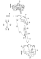
- FIG. 1 is an installation state diagram showing a state in which an assist grip according to a first embodiment of the present invention is provided in an automobile.
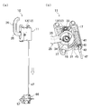
- FIG. 2 is a partially exploded perspective view showing an interlocking portion of the assist grip according to the first embodiment of the present invention.
- FIG. 3 is an exploded perspective view showing an interlocking portion of the assist grip according to the first embodiment of the present invention.
- FIG. 4 is an exploded perspective view showing a main part of the assist grip according to the first embodiment of the present invention.
- FIGS. 5A and 5B show a stored state of the assist grip according to the first embodiment of the present invention, wherein FIG. 5A is an external perspective view, and FIG. 5B is an enlarged view of a main part.
- FIGS. 6A and 6B show a protruding state of the assist grip according to the first embodiment of the present invention, wherein FIG. 6A is an external perspective view and FIG. 6B is an enlarged view of a main part.
- FIGS. 7A and 7B show the storage state of the assist grip according to the first embodiment of the present invention.
- FIG. 7A is an external perspective view
- FIG. 7B is an enlarged view of a main part.
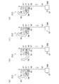
- FIGS. 8A and 8B schematically show the operation of the assist grip according to the second embodiment of the present invention, wherein FIG. 8A is a schematic diagram of a stored state, FIG. 8B is a schematic diagram of a projected state, and FIG. 8C is a closed door.
- FIG. 8A is a schematic diagram of a stored state
- FIG. 8B is a schematic diagram of a projected state
- FIG. 8C is a closed door.
- FIG. 7D is a schematic view of the storage maintenance state in the case, and FIG. 7D is a schematic view of the storage maintenance state when the door is open.
- FIGS. 9A and 9B schematically show the operation of the assist grip according to the third embodiment of the present invention.
- FIG. 9A is a schematic diagram of a stored state
- FIG. 9B is a schematic diagram of a protruding state
- FIG. It is.
- FIG. 1 shows an appearance of an assist grip 10 according to the first embodiment and an example of installation on an automobile.
- the assist grip 10 includes a grip movable body 11 provided with a grip body 26 gripped by an occupant (not shown) of the automobile 1 and a door 2 of the automobile 1 connected to the grip movable body 11 and the grip body 26. It has an interlocking portion 40 interposed therebetween, and an interlocking release portion 39 (see FIG. 4) connected to the interlocking portion 40 and connected to the grip body 26.
- the assist grip 10 is attached to, for example, the B pillar 4 of the automobile 1. More specifically, since a seat belt (not shown) is generally attached to the B pillar 4, the assist grip 10 is disposed at a location that does not interfere with the seat belt installation location.
- the grip movable body 11 is attached near a corner which is a connection point between the B pillar 4 and the roof 3, and the interlocking unit 40 is between the B pillar 4 and the door 2, and rotates the door 2. It is mounted near the shaft.
- the interlocking unit 40 changes the assist grip 10 to the protruding state or the stored state by interlocking the respective units.
- the protruding state is a state in which the grip body 26 protrudes, and is realized in conjunction with the opening of the door 2.
- the housed state is a state in which the grip body 26 is housed, and is realized in conjunction with the closing of the door 2.
- the assist grip 10 is changed to the storage maintaining state by the interlock release unit 39.
- the stored state is a state in which the grip body 26 is stored, and does not interlock with opening and closing of the door 2.
- the forward direction of the vehicle 1 is defined as the forward direction
- the backward direction is defined as the backward direction
- the direction of the vehicle height is defined as the upper direction and the lower direction
- the direction of the vehicle width is defined as the right direction and the left direction based on the stored state. .
- FIG. 2 shows the interlocking unit 40 partially disassembled
- FIG. 3 shows the interlocking unit 40 entirely disassembled.
- the interlocking section 40 has an activation link member 66 and a wire 47.
- the activation link member 66 has a wire body connected to the grip movable body 11 from the rear of the hexagonal interlocking part case 48 formed in a substantially quadrangular shape. 47 is passed from above.
- the interlocking unit case 48 includes an interlocking unit case main body 49 and a cap 50, and a pressing interlocking member 55 is provided inside the interlocking unit case 48 together with the lower end of the wire 47. Will be accommodated.
- the interlocking part case main body 49 is formed on the left and right side surfaces with a rail portion 51 protruding toward the left and right sides and extending forward and backward, and a first portion for passing a rear portion of the contact member 56 through the rear surface.
- An advance / retreat hole 52 is formed, and a wire hole 53 for passing the wire 47 is formed on the upper surface.
- the cap 50 has two second advance / retreat holes 54 formed on the front surface thereof so that the front part of the contact member 56 can pass therethrough.
- the pressing interlocking member 55 includes a contact member 56 and a link arm 58 connected to the contact member 56.
- the contact member 56 includes a rod-shaped contact main body 57 extending rearward, a base 62 formed in front of the contact main body 57, and two rod-shaped extending frontward from the base 62. And a section 63.
- the base 62 is formed as a pair of left and right parts at a front part of the contact main body part 57 through a space 64 opened up and down, and protrudes left and right, respectively.
- the bases 62 face each other with a space therebetween via a space 64, and are connected to each other by a base connecting portion 65 arranged in the space 64.
- the bar-shaped portion 63 is connected to the base 62 and is configured as a pair of left and right.
- the rod-shaped portions 63 face each other at intervals.
- the link arm 58 is plate-shaped, and has a link groove 59 which is curved from the upper side to the rear side. More specifically, the link groove 59 is opened at an upper end of the link arm 58 and closed at a rear end of the link arm 58.
- a link shaft portion 60 protruding left and right is formed below the link groove 59 at a rear portion, and a wire fixing hole 61 penetrating left and right is formed at a front portion.
- the above components are assembled as follows.
- the base arm 65 of the contact member 56 is passed through the link groove 59 of the link arm 58, so that the link arm 58 is disposed in the gap 64 of the contact member 56.
- the link shaft portion 60 of the link arm 58 is supported by the interlocking portion case main body 49, and the base 62 of the link arm 58 is disposed on the rail portion 51 of the interlocking portion case main body 49, and the abutment main body portion 57 of the abutment member 56 is provided.
- the wire 47 is slackened upward by the contact main body portion 57 of the contact member 56 protruding from the interlocking portion case 48, and the contact main body portion 57 is The wire 47 is pulled downward by being pushed into the case 48. More specifically, when no external force is applied to the contact main body 57, the contact member 56 is pushed rearward by the restoring force of the link urging member, and the contact main body 57 moves the first advance / retreat hole 52. And protrudes from the interlocking part case 48.
- the link arm 58 is arranged such that the wire fixing hole 61 side is located above the contact main body 57 and the wire 47 is loose.
- the link groove 59 of the link arm 58 is formed to be curved from above to the rear, and the base connecting portion 65 of the contact member 56 is passed from above the link groove 59.
- a starting link member in which the link arm 58 is turned upside down and passed through the base connecting portion 65 is used. That is, in the modified example, the link groove of the link arm is curved from below to the rear, and the base connecting portion is passed from below the link groove.
- the wire 47 is pulled downward by the contact main body portion of the contact member protruding from the interlocking portion case, and is pushed upward by the contact main body portion being pushed into the interlocking portion case. Loosen towards.
- the principle of operation is the same as that of the interlocking unit 40.
- FIG. 4 shows the disassembled grip movable body 11.
- the grip movable body 11 includes a hexagonal grip case 12 formed in a substantially rectangular shape, a grip body 26 accommodated in the grip case 12, and a grip connected to the grip body 26. It has a damper 33 accommodated in the case 12 and a spring 34 attached to the grip body 26. Further, the grip movable body 11 is connected to an interlock release unit 39 to which the upper end of the wire 47 is connected.
- the grip case 12 includes a grip case body 13, a first cover 23, and a second cover 24.
- the grip case body 13 is opened at a grip body housing portion 14 that is a substantially circular space, a damper housing portion 15 that is a space connected above the grip body housing portion 14, and a rear portion of the grip body housing portion 14.
- the grip main body movable region 16 and a housing rail 17 which is a vertically linear space connected to the front of the grip body housing 14 are formed.
- the grip case main body 13 is formed with a shaft portion 18 protruding rightward in the grip main body housing portion 14 and an overhang portion 19 protruding inward.
- the inside of the overhang portion 19 is the storage regulating surface 20, while the outside facing the grip body movable region 16 is the protrusion regulating surface 21.
- the grip case main body 13 has a cutout hole 22 formed at a lower portion of the accommodation rail portion 17.
- the grip body 26 has a substantially circular rotating part 27 and a grip part 35 extending from the rear part of the rotating part 27, and rotates around a single axis.
- the rotating portion 27 has a shaft hole 28 formed through the center thereof, and a spring housing groove 29 is formed around the shaft hole 28.
- a first gear portion 30, a second gear portion 31, and a protrusion 32 are formed on the outer peripheral surface of the rotating portion 27.
- the first gear unit 30 is formed on the upper surface of the rotating unit 27, and the second gear unit 31 is formed from the front surface to the lower surface of the rotating unit 27.
- the protrusion 32 is formed on the lower surface of the rotating unit 27.
- the grip 35 has a substantially L-shaped hook shape, and has a grip base 36 protruding from the rear surface of the rotating part 27, a grip intermediate part 37 bent substantially at right angles to the grip base 36, and a grip intermediate part 37.
- 37 has a gripping front end portion 38 bent forward from the front end.
- the damper 33 is a so-called braking device, and is, for example, an oil damper or an air damper having a gear.
- the spring 34 is a so-called torsion spring and has two ends.
- the interlock release section 39 has a so-called latch structure, and includes a sliding section 41 connected to the wire 47 of the interlock section 40, a locked section 42 attached to the sliding section 41, and a locked section 42. And a locking portion 43 for locking the lock.
- the sliding portion 41 is a substantially rectangular parallelepiped.
- a mounting groove 44 is formed on a front surface of the sliding portion 41 to which an upper end portion of the wire 47 is mounted, a rack portion 45 is formed on a rear surface, and a locked portion 42 is mounted on a lower end portion.
- the locking portion 43 is locked by being pushed into the locked portion 42, and is released from the locked portion 42 by being pushed again.
- the latch structure may have any configuration.
- the locking portion 43 has a convex shape, a hook shape, a key shape, and a pin shape
- the locked portion 42 has a groove shape, a heart cam, and a rotating cam. And so on.
- the above components are assembled as follows.
- the upper end of the wire 47 is attached to the mounting groove 44 of the sliding portion 41, and the wire 47 and the locked portion 42 are arranged in parallel at the lower end of the sliding portion 41.
- the damper 33 is attached to the damper accommodating section 15 with the screw 5
- the sliding section 41 is attached to the accommodating rail section 17, and the locking section 43 is attached to the notch hole 22.
- the wire 47 is passed through the cutout hole 22.
- the grip body 26 is attached to the grip case 12
- the rotating part 27 of the grip body 26 is disposed in the grip body housing part 14 and the shaft part 18 is passed through the shaft hole 28.
- the spring 34 is attached to the spring receiving groove 29, and one end is supported by the rotating part 27.
- the first gear portion 30 meshes with the damper 33, and the second gear portion 31 meshes with the rack portion 45 of the sliding portion 41.
- the first cover 23 is attached to the right side surface of the grip case body 13 with the screw 5, and the other end of the spring 34 is supported by the first cover 23.
- the second cover 24 is attached with screws 5 from the right side surface of the first cover 23 to the rear surface of the grip case body 13. At this time, the grip 35 of the grip body 26 is passed through the movable area hole 25 formed in the second cover 24.
- FIGS. 5A and 5B show the assist grip 10 in a stored state
- FIGS. 6A and 6B show the assist grip 10 in a protruding state
- FIGS. The assist grip 10 in the housed state is shown.
- the grip body 26 is in a state in which the grip 35 extends outward away from the grip case 12. While the grip body 26 rotates, the first gear portion 30 of the rotating portion 27 and the damper 33 mesh with each other, so that the operation is performed smoothly. With the rotation of the grip body 26, the sliding portion 41 slides on the storage rail portion 17 and is arranged at the upper portion. At that time, since the wire 47 is loose, the tension of the wire 47 does not hinder the sliding of the sliding portion 41. Thus, the assist grip 10 changes from the stored state to the protruded state.
- the sliding portion 41 of the grip movable body 11 is moved by the rack and pinion mechanism by the rack and pinion mechanism. In conjunction with 26, it is pushed downward in the storage rail 17.
- the locked portion 42 of the sliding portion 41 and the locking portion 43 of the grip case 12 are locked by the latch structure, and the movement of the sliding portion 41 is restricted.
- the assist grip 10 changes from the stored state to the stored state.
- an activation link member in which the link arm 58 is turned upside down is used, and operates as follows. For example, when the door 2 is opened, an external force interlocked with the door 2 is applied to push the contact main body of the activation link member, and the wire 47 is pulled downward to be in the housed state. When the door 2 is closed, the contact main body is released from external force interlocked with the door 2 and protrudes, and the wire 47 is slackened upward to be in a protruding state. The stored state is the same as in the first embodiment.
- the grip movable body 11 provided with the grip body 26 gripped by the occupant of the automobile 1, the door 2 and the grip body 26 of the automobile 1 connected to the grip movable body 11 And an interlocking release portion 39 connected to the interlocking portion 40 and connected to the grip body 26.
- the interlocking unit 40 changes the assist grip 10 to a protruding state or a stored state in conjunction with opening and closing of the door 2.
- the sliding portion 41 of the interlocking release portion 39 and the grip body 26 are interlocked by the rack and pinion mechanism, the movement of the sliding portion 41 is regulated, so that the grip body is opened regardless of whether the door 2 is opened or closed. 26 stops and enters the storage maintaining state.
- the assist grip 10 can select whether or not to be linked with opening and closing of the door 2.
- the rack and pinion mechanism is realized by the rack portion 45 of the sliding portion 41 and the second gear portion 31 of the rotating portion 27 of the grip body 26, so that the grip body 27 is smoothly rotated. And the whole can be reduced in size. With the small assist grip 10, even the B pillar 4 to which a seat belt is generally attached can be easily attached to a location that does not interfere with the installation location of the seat belt.
- the assist grip 10 is attached to the B pillar 4, the A pillar (not shown), the roof 3, etc. are empty, and the space in the vehicle can be effectively utilized. In addition, the occupant can easily grip the grip body 26 when getting on and off.
- the link portion 40 (the wire 47 and the activation link member 66) is connected to the grip main body 26.
- the transmission of the operation and the regulation of the operation of the interlocking unit 40 can be performed by the sliding unit 41.
- the grip body 26 and the sliding portion 41 are assembled, the entire body is reduced in size, and can be easily installed on the automobile 1.
- the interlocking release section 39 of the assist grip 10 includes a sliding section 41 connected to the wire 47 of the interlocking section 40, a locked section 42 attached to the sliding section 41, and the locked section 42.
- the first gear portion 30 of the rotating portion 27 of the grip body 26 is engaged with the damper 33.
- the grip body 26 is braked by the damper 33. Therefore, a smooth operation can be realized.
- the grip body 26 has the substantially circular rotating part 27 and the grip part 35 extending from the rear part of the rotating part 27, and rotates about a single axis. Therefore, the installation location on the automobile 1 is small and sufficient.
- the grip portion 35 of the grip body 26 can be appropriately stored. Therefore, the space in the vehicle can be effectively used, and the grip body 26 can be shielded in appearance when the door 2 is open. For example, even when the assist grip 10 is attached later to a nursing care vehicle or the like, when not in use, the grip main body 26 is stored, so that the external appearance is maintained. It is useful because it protrudes in a proper state.
- FIGS. 8A, 8B, 8C, and 8D schematically show the operation of the assist grip 210 according to the second embodiment.
- a start link member 266 in which the link arm 58 is turned upside down is provided.
- a configuration different from the first embodiment will be mainly described, and a description of a similar configuration will be omitted as appropriate.
- the assist grip 210 is connected to the sliding portion 41 through the wire 47 passing through the fixed pulley 6 from above the grip case 12. Have been.
- the sliding portion 41 has a built-in permanent magnet 47, and the permanent magnet 47 is connected to the wire 47.
- the assist grip 210 when the wire 47 is loosened, the grip main body 26 is stored and changes to a stored state (FIG. 8A), and when the wire 47 is pulled, the grip main body 26 protrudes and protrudes. The state changes (FIG. 8B). Further, in the protruding state, the locked part 42 is locked by the locking part 43, so that the state is changed to the storage maintaining state (FIGS. 8C and 8D).
- the sliding portion 41 is interlocked with the grip body 26 by the rack and pinion mechanism, and is pushed downward in the housing rail section 17. It is.
- the locked portion 42 of the sliding portion 41 and the locking portion 43 of the grip case 12 are locked by the latch structure, and the movement of the sliding portion 41 is restricted.
- the assist grip 210 changes from the stored state to the stored state.
- FIG. 8D in this stored state, when the door 2 is opened, the contact main body 57 is released from external force from the door 2, protrudes, and the wire 47 is pulled downward. Then, the permanent magnet 7 separates while the movement of the sliding portion 41 is restricted, and only the wire 47 is pulled. Therefore, the sliding portion 41 does not slide, and the grip main body 26 interlocked with the sliding portion 41 remains stopped.
- a spring (not shown) may be incorporated in the sliding portion 41 instead of the permanent magnet 7.
- the assist grip 210 according to the second embodiment also has the same effect as the assist grip 10 according to the first embodiment.
- FIGS. 9A, 9B, and 9C schematically show the operation of the assist grip 310 according to the third embodiment.
- a configuration different from the first embodiment will be mainly described, and a description of a similar configuration will be omitted as appropriate.
- the assist grip 310 includes a general grip main body 326, and the interlock release unit 339 includes a grip. It is provided separately from the main body 326.
- the operation part 46 is attached to the sliding part 41 of the interlock release part 339.
- the assist grip 310 changes to the stored state (FIG. 9C).
- the assist grip 310 changes to a stored state or a protruding state (FIG. 9B) in conjunction with opening and closing of the door 2.
- the fourth embodiment does not include an activation link member, and the lower end of a wire 47 as an interlocking part is directly connected to the door 2.
- the wire 47 exposed between the door 2 and the B pillar 4 is covered with, for example, a coil spring or the like, and protected so that the wire 47 is not pinched by the door 2.
- the interlock release unit may have any structure instead of the latch structure as long as the structure restricts movement.
- the movement of the sliding portion is restricted.
- an electromagnet is provided at the lower end of the sliding portion, and the movement of the sliding portion is regulated, for example, by operating or disconnecting a wireless or wired operating portion by operating the operating portion. Further, for example, the movement of the sliding portion is regulated by inserting and penetrating the rod-shaped operating portion from the outside of the clip case.
Landscapes
- Engineering & Computer Science (AREA)
- Transportation (AREA)
- Mechanical Engineering (AREA)
- Passenger Equipment (AREA)
Abstract
ドアの開閉と連動させるか否かを選択できるアシストグリップを提供する。アシストグリップ10は、グリップ本体26を有するグリップ可動体11と、グリップ可動体11に接続されてドアとグリップ本体26との間に介在したワイヤー47及び起動リンク部材66と、ワイヤー47に接続されると共にグリップ本体26の回転部27と連動する摺動部41と、摺動部41を係止するラッチ構造とを有し、把持部35が押されると、摺動部41がラッチ構造によって係止し、摺動部41と共にグリップ本体26が規制される。
Description
本発明は、自動車などの車内に備えられて乗員が把持するアシストグリップに関するものである。
従来、乗降時または走行時に乗員が自身の体を支えるために掴む手摺として、車内にアシストグリップが備えられている。例えば、下記特許文献1に記載されたアシストグリップ取付機構は、自動車のドア枠と、アシストグリップが取り付けられたAピラーとの間にワイヤーが内蔵され、このワイヤーの一方端がドアに連結され、反対側の他方端がアシストグリップに連結されている。ドアが閉じている状態では、アシストグリップは、ピラーの内側に引き込まれる方向に向けて、バネによって付勢されている。一方、ドアが開くと、ワイヤーが引っ張られると共にアシストグリップがコイルバネの復元力に抗して引っ張られ、アシストグリップがAピラーの外側に突出する。
しかし、上記したとおり、アシストグリップ取付機構は、ドアが開くことに連動して、アシストグリップが自動的に突出するため、乗員がアシストグリップを要しない場合、アシストグリップが乗降の妨げとなる場合がある。
本発明は、この様な実情に鑑みて提案されたものである。すなわち、ドアの開閉と連動させるか否かを選択することができるアシストグリップの提供を目的とする。
上記目的を達成するために、本発明に係るアシストグリップは、自動車の乗員が把持するグリップ本体部と、前記自動車のドアと前記グリップ本体との間に介在し、前記ドアが開くことで、前記グリップ本体が突出した突出状態に変化させ、前記ドアが閉じることで、前記グリップ本体が収納された収納状態に変化させる連動部と、前記連動部に備えられ、前記収納状態において動きが規制されることで、前記収納状態を維持させる連動解除部と、を有する、ことを特徴とする。
本発明に係るアシストグリップは、前記連動解除部が前記グリップ本体に接続された、ことを特徴とする。
本発明に係るアシストグリップは、前記グリップ本体が操作されることで、前記連動解除部の動きが規制される、ことを特徴とする。
本発明に係るアシストグリップは、前記グリップ本体が単一の軸を軸として回転することで、前記突出状態または前記収納状態に変化する、ことを特徴とする。
本発明に係るアシストグリップは、前記連動解除部がラッチ構造である、ことを特徴とする。
本発明に係るアシストグリップは、前記グリップ本体がギヤ部を有し、前記連動解除部が、前記ギヤ部と噛み合うラック部を有する、ことを特徴とする。
本発明に係るアシストグリップは、前記グリップ本体と接触したダンパーを有する、ことを特徴とする。
本発明に係るアシストグリップは、前記自動車のBピラーに備えられた、ことを特徴とする。
本発明に係るアシストグリップは、前記グリップ本体が、回転部と、この回転部から伸びた把持部とを有し、前記連動解除部が、前記連動部に接続された摺動部と、この摺動部が係止される係止部とを有し、前記回転部と前記摺動部とが噛み合い、前記収納状態における前記把持部が、前記突出状態への変化において回転しながら突出する方向と反対方向に押されることで、前記摺動部が前記係止部に係止される、ことを特徴とする。
本発明に係るアシストグリップは、自動車の乗員が把持するグリップ本体部と、自動車のドアとグリップ本体との間に介在し、ドアが開くことで、グリップ本体が突出した突出状態に変化させ、ドアが閉じることで、グリップ本体が収納された収納状態に変化させる連動部と、連動部に備えられ、収納状態において動きが規制されることで、収納状態を維持させる連動解除部とを有している。すなわち、連動部に備えられた連動解除部が規制されることで、連動部の動作の一部が停止し、ドアの開閉に際し収納状態が維持される。したがって、乗員は、アシストグリップを要しない場合に、アシストグリップを収納させたままドアを開閉することができる。一方で、連動解除部が解放されることで、連動部が動作し、ドアの開閉に際し突出状態と収納状態とに変化する。このように、本発明に係るアシストグリップは、ドアの開閉と連動させるか否かを選択することができる。
本発明に係るアシストグリップは、連動解除部がグリップ本体に接続されている。すなわち、連動部からグリップ本体への動作の伝達と、連動部の動作の規制とを、連動解除部で担うことができる。また、グリップ本体と連動解除部とが集合しているため、全体が小型となり、自動車への設置が容易である。
本発明に係るアシストグリップは、グリップ本体が操作されることで、連動解除部の動きが規制される。すなわち、グリップ本体で連動解除部を操作することができ、ドアの開閉と連動させるか否かを選択することができる。
本発明に係るアシストグリップは、グリップ本体が単一の軸を軸として回転することで、突出状態または収納状態に変化する。すなわち、グリップ本体は、単一の軸が自動車に取り付けられる。したがって、自動車への設置箇所が狭小で足りる。なお、一般的なアシストグリップは、把持部の両端に軸を有し、両軸が自動車に取り付けられる。そのため、広い設置箇所を要する。
また、回転運動により突出状態または収納状態に変化することで、グリップ本体における軸以外の部分を適切に収納することができる。したがって、自動車内の空間を有効に活用することができ、また、ドアが開いた状態において、外観上、グリップ本体を遮蔽することができる。
本発明に係るアシストグリップは、連動解除部がラッチ構造である。例えば、いわゆるストライカーによって連動解除部が係止する構造であれば、適切に連動解除部の動きが規制される。したがって、ドアの開閉と連動させるか否かの切り替えを、確実に実現することができる。
本発明に係るアシストグリップは、グリップ本体がギヤ部を有し、連動解除部が、ギヤ部と噛み合うラック部を有している。この構成により、グリップ本体は、連動解除部の直線運動が伝達されて回転運動する。したがって、グリップ本体を円滑に回転させることができ、また、全体を小型にすることができる。小型のアシストグリップであれば、例えば、Bピラーであっても、シートベルトが取り付けられた箇所と干渉しない箇所に容易に取り付けることができる。なお、一般的に、シートベルトは、Bピラーに取り付けられている。
本発明に係るアシストグリップは、グリップ本体と接触したダンパーを有している。この構成により、グリップ本体は、ダンパーによって制動される。したがって、滑らかな動作を実現することができる。
本発明に係るアシストグリップは、自動車のBピラーに備えられている。したがって、Aピラーやルーフなどが空き、自動車内の空間を有効に活用することができる。また、乗降時に把持しやすくすることができる。
本発明に係るアシストグリップは、グリップ本体が、回転部と、この回転部から伸びた把持部とを有し、連動解除部が、連動部に接続された摺動部と、この摺動部が係止される係止部とを有し、回転部と摺動部とが噛み合い、収納状態における把持部が、突出状態への変化において回転しながら突出する方向と反対方向に押されることで、摺動部が係止部に係止される。したがって、グリップ本体の把持部を操作することで、ドアの開閉と連動させるか否かを選択することができる。
以下に、本発明の第一実施形態に係るアシストグリップを図面に基づいて説明する。図1は、第一実施形態に係るアシストグリップ10の外観および自動車への設置例が示されている。
アシストグリップ10は、自動車1の乗員(図示省略。)が把持するグリップ本体26が備えられたグリップ可動体11と、このグリップ可動体11に接続されて自動車1のドア2とグリップ本体26との間に介在した連動部40と、この連動部40に接続されると共にグリップ本体26に接続された連動解除部39(図4参照。)とを有している。アシストグリップ10は、例えば、自動車1のBピラー4に取り付けられている。詳説すれば、Bピラー4には、一般的にシートベルト(図示省略。)が取り付けられているため、アシストグリップ10は、シートベルトの設置箇所と干渉しない箇所に配置される。例えば、グリップ可動体11は、Bピラー4とルーフ3との連接箇所である角部の近傍に取り付けられ、連動部40は、Bピラー4とドア2との間であって、ドア2の回転軸近傍に取り付けられている。各部が連動することで、連動部40は、アシストグリップ10を、突出状態または収納状態に変化させる。突出状態は、グリップ本体26が突出した状態であり、ドア2が開くことに連動して実現する。一方で、収納状態は、グリップ本体26が収納された状態であり、ドア2が閉じることに連動して実現する。さらに、連動解除部39によって、アシストグリップ10は、収納維持状態に変化する。収納維持状態は、グリップ本体26が収納された状態であり、ドア2の開閉と連動しない。なお、以下の説明では、収納状態を基準として、自動車1の前進方向を前方とし、後退方向を後方とし、車高の方向を上方および下方とし、車幅の方向を右方および左方とする。
ここで、連動部40を図面に基づいて説明する。図2は、一部が分解された連動部40が示され、図3は、すべてが分解された連動部40が示されている。
図1に示されているとおり、連動部40は、起動リンク部材66とワイヤー47とを有している。起動リンク部材66は、ほぼ四角形に形成された六面体の連動部ケース48の後方から、この連動部ケース47に対して進退可能な当接本体部57が突出し、グリップ可動体11に接続されたワイヤー47が、上方から通されている。図2および図3に示されているとおり、連動部ケース48は、連動部ケース本体49とキャップ50とから構成され、連動部ケース48の内側に、押圧連動部材55がワイヤー47の下端部と共に収容される。連動部ケース本体49は、左右側面に、左右側方に向けてそれぞれ突出すると共に前後に伸びたレール部51が形成され、後方面に、当接部材56の後部が通されるための第一進退孔52が形成され、上方面に、ワイヤー47が通されるためのワイヤー孔53が形成されている。一方、キャップ50は、前方面に、当接部材56の前部が通されるための第二進退孔54が二つ形成されている。
押圧連動部材55は、当接部材56と、この当接部材56と連結されたリンクアーム58とから構成されている。当接部材56は、後方に向けて伸びた棒状の当接本体部57と、この当接本体部57の前方に形成された基部62と、この基部62から前方に向けて伸びた二つの棒状部63とから構成されている。基部62は、当接本体部57の前部において、上下に開放された空隙64を介して、左右一対で構成され、左右に向けてそれぞれ突出している。基部62は、空隙64を介して間隔を空けて互いに対面し、空隙64に配置された基連結部65によって互いが連結されている。棒状部63は、基部62に連結されて左右一対で構成されている。棒状部63は、間隔を空けて互いに対面している。
リンクアーム58は、板状であり、上方から後方に至って湾曲したリンク溝59が形成されている。詳説すれば、リンク溝59は、リンクアーム58の上方の端において開放され、リンクアーム58の後方の端において閉塞している。また、リンクアーム58は、後部であって、リンク溝59の下方において、左右に突出したリンク軸部60が形成され、前部において、左右に貫通したワイヤー固定孔61が形成されている。
上記した各部は、次のとおり組み付けられる。当接部材56の基連結部65が、リンクアーム58のリンク溝59に通されることで、リンクアーム58が当接部材56の空隙64に配置される。リンクアーム58のリンク軸部60は、連動部ケース本体49に支持され、リンクアーム58の基部62は、連動部ケース本体49のレール部51に配置され、当接部材56の当接本体部57は、連動部ケース本体49の第一進退孔52に通される。この状態で、連動部ケース本体49にキャップ50が取り付けられると、当接部材56の棒状部63が、キャップ50の第二進退孔54に通される。その際、例えばコイルバネなどのリンク付勢部材(図示省略。)が棒状部63に通され、当接部材56の基部62とキャップ50との間にリンク付勢部材が配置される。リンクアーム58のワイヤー固定孔61に、ワイヤー47の下端部が取り付けられて固定され、このワイヤー47が連動部ケース本体49のワイヤー孔53に通される。
上記のとおり構成された連動部40によれば、当接部材56の当接本体部57が連動部ケース48から突出することでワイヤー47が上方に向けて緩み、当接本体部57が連動部ケース48に押し込まれることでワイヤー47が下方に引っ張られる。詳説すれば、当接本体部57に外力が加えられていない場合、リンク付勢部材の復元力によって当接部材56が後方に向けて押され、当接本体部57が第一進退孔52を通って連動部ケース48から突出している。リンクアーム58はワイヤー固定孔61側が当接本体部57よりも上方に配置され、ワイヤー47が緩んだ状態である。
当接本体部57に外力が加えられた場合、当接本体部57が前方に向けて押し込まれ、当接部材56が前方に移動すると共にリンク付勢部材が圧縮される。その際、基部62が連動部ケース48のレール部51に沿って前方に移動すると共に、基連結部65がリンクアーム58のリンク溝59に沿って移動することで、リンクアーム58がリンク軸部60を軸として下方に向けて回転し、ワイヤー固定孔61側が引き下げられて当接本体部57よりも下方に配置される。同時に、ワイヤー47が下方に引っ張られる。
当接本体部57が外力から解放されると、リンク付勢部材が伸長し、リンク付勢部材の復元力によって当接部材56が後方に移動すると共に、当接本体部57が第一進退孔52を通って連動部ケース48から突出する。再びワイヤー47が緩む。
なお、上記したとおり、第一実施形態では、リンクアーム58のリンク溝59は、上方から後方に至って湾曲して形成され、リンク溝59の上方から当接部材56の基連結部65が通されているが、第一実施形態の変形例では、リンクアーム58が上下に反転して基連結部65に通された起動リンク部材が用いられる。すなわち、変形例では、リンクアームのリンク溝は、下方から後方に至って湾曲しており、リンク溝の下方から基連結部が通されている。このリンクアームによれば、当接部材の当接本体部が連動部ケースから突出することでワイヤー47が下方に引っ張られ、当接本体部が連動部ケースに押し込まれることでワイヤー47が上方に向けて緩む。動作の原理は、連動部40と同じである。
次に、グリップ可動体11を図面に基づいて説明する。図4は、分解されたグリップ可動体11が示されている。
図4に示されているとおり、グリップ可動体11は、ほぼ四角形に形成された六面体のグリップケース12と、このグリップケース12に収容されるグリップ本体26と、このグリップ本体26に接続されてグリップケース12に収容されるダンパー33と、グリップ本体26に取り付けられるバネ34とを有している。また、グリップ可動体11は、ワイヤー47の上端部が接続された連動解除部39が接続されている。
グリップケース12は、グリップケース本体13、第一カバー23および第二カバー24から構成されている。グリップケース本体13は、ほぼ円形の空間であるグリップ本体収容部14と、このグリップ本体収容部14の上方に連接された空間であるダンパー収容部15と、グリップ本体収容部14の後方において開放されたグリップ本体可動域部16と、グリップ本体収容部14の前方に連接された上下に直線状の空間である収容レール部17とが形成されている。グリップケース本体13は、グリップ本体収容部14において、右側方に向けて突出した軸部18が形成され、また、内側に向けて張り出した張出し部19が形成されている。張出し部19のうち、内側が収納規制面20であり、一方、グリップ本体可動域部16に面した外側が突出規制面21である。また、グリップケース本体13は、収容レール部17の下部に切欠き孔22が形成されている。
グリップ本体26は、ほぼ円形の回転部27と、この回転部27の後部から伸びた把持部35とを有し、単一の軸を軸として回転する。回転部27は、中央が貫通して軸孔28が形成され、この軸孔28の周囲にバネ収容溝29が形成されている。また、回転部27の外周面に、第一ギヤ部30、第二ギヤ部31および突起部32が形成されている。第一ギヤ部30は、回転部27の上面に形成され、第二ギヤ部31は、回転部27の前面から下面に渡って形成されている。突起部32は、回転部27の下面に形成されている。把持部35は、ほぼL字型のフック状であり、回転部27の後面から突出した把持基部36と、この把持基部36に対してほぼ直角に折れ曲がった把持中間部37と、この把持中間部37の先端から前方に向けて折れ曲がった把持先端部38とを有している。
ダンパー33は、いわゆる制動装置であり、例えば、ギヤを有したオイルダンパーやエアダンパーなどである。バネ34は、いわゆるトーションバネであり、二つの端部を有している。
連動解除部39は、いわゆるラッチ構造であり、連動部40のワイヤー47に接続された摺動部41と、この摺動部41に取り付けられた被係止部42と、この被係止部42が係止される係止部43とを有している。摺動部41は、ほぼ直方体であり、前面に、ワイヤー47の上端部が取り付けられる取付溝44が形成され、後面に、ラック部45が形成され、下端部に、被係止部42が取り付けられている。係止部43は、被係止部42に押し込まれることで係止され、再度押されることで、被係止部42から外れる。ラッチ構造は、どのような構成であってもよく、例えば、係止部43が、凸形状、フック形状、カギ形状、ピン形状であり、被係止部42が、溝形状、ハートカム、回転カムなどである。
上記した各部は、次のとおり組み付けられる。ワイヤー47の上端部が、摺動部41の取付溝44に取り付けられ、ワイヤー47と被係止部42とが摺動部41の下端において並列して配置される。グリップケース本体13において、ダンパー収容部15にダンパー33がネジ5で取り付けられ、収容レール部17に摺動部41が取り付けられ、切欠き孔22に係止部43が取り付けられる。ワイヤー47は、切欠き孔22に通されている。グリップ本体26がグリップケース12に取り付けられる際、グリップ本体26の回転部27が、グリップ本体収容部14に配置されると共に軸部18が軸孔28に通される。バネ34は、バネ収容溝29に取り付けられ、片方の端部が回転部27に支持される。第一ギヤ部30が、ダンパー33と噛み合わさり、第二ギヤ部31が、摺動部41のラック部45と噛み合わさる。第一カバー23は、グリップケース本体13の右側面にネジ5で取り付けられ、バネ34のもう片方の端部が第一カバー23に支持される。第二カバー24は、第一カバー23の右側面からグリップケース本体13の後面に渡ってネジ5で取り付けられる。その際、第二カバー24に形成された可動域孔25にグリップ本体26の把持部35が通される。
上記のとおり構成されたアシストグリップ10によれば、ワイヤー47が引っ張られることで、グリップ本体26が収納されて収納状態に変化し、ワイヤー47が緩むことで、グリップ本体26が突出して突出状態に変化する。さらに、突出状態において、被係止部42が係止部43に係止されることで、収納維持状態に変化する。ここで、収納状態、突出状態および収納維持状態を図面に基づいて説明する。図5(a)(b)は、収納状態のアシストグリップ10が示され、図6(a)(b)は、突出状態のアシストグリップ10が示され、図7(a)(b)は、収納維持状態のアシストグリップ10が示されている。
図5(a)(b)に示されているとおり、収納状態では、例えば、ドア2が閉じることで、ドア2からの外力が加えられて起動リンク部材66の当接本体部57が押し込まれ、ワイヤー47が下方に向けて引っ張られている。グリップ可動体11において、摺動部41は、ワイヤー47によって下方に引っ張られ、収容レール部17の下部に配置されている。グリップ本体26は、回転部27の第二ギヤ部31が摺動部41のラック部45と噛み合わさっているため、把持部35がグリップケース12に近接した状態が維持される。その際、バネ34は、自然長よりも圧縮している。この収納状態において、ドア2が開くと、アシストグリップ10は収納状態から突出状態に変化する。
図6(a)(b)に示されているとおり、突出状態では、ドア2が開くことで、当接本体部57がドア2からの外力から解放されて突出し、ワイヤー47が上方に向けて緩む。ワイヤー47が緩むことにより、摺動部41がワイヤー47からの外力から解放されると共に、いわゆるラック・ピニオン機構によって摺動部41と連動するグリップ本体26も解放される。グリップ可動体11において、グリップ本体26は、圧縮していたバネ34の復元力によって、軸部18を軸として回転し(図6(a)(b)において左回りに回転し)、把持基部36が、グリップケース12における張出し部19の突出規制面21に当たって止まる。グリップ本体26は、把持部35がグリップケース12から離れて外側に張り出した状態となる。グリップ本体26が回転する間、回転部27の第一ギヤ部30とダンパー33とが噛み合うことで、滑らかに動作する。グリップ本体26の回転に伴って、摺動部41は、収容レール部17においてスライドして上部に配置される。その際、ワイヤー47は緩んでいるため、ワイヤー47の張力は、摺動部41のスライドの妨げとはならない。このようにして、アシストグリップ10は収納状態から突出状態に変化する。
再びドア2が閉じると、図5(a)(b)に示されているとおり、ドア2からの外力が加えられて起動リンク部材66の当接本体部57が押し込まれ、ワイヤー47が下方に向けて引っ張られる。ワイヤー47が引っ張られることにより、グリップ可動体11において、摺動部41は、ワイヤー47によって下方に引っ張られ、収容レール部17においてスライドして下部に配置される。摺動部41のスライドに伴って、グリップ本体26は、ラック・ピニオン機構によって摺動部41と連動し、バネ34の弾性力に抗して、軸部18を軸として回転し(図5(a)(b)において右回りに回転し)、把持部35がグリップケース12に近接する。このようにして、アシストグリップ10は突出状態から収納状態に変化する。この収納状態において、グリップ本体26が操作されると、連動解除部39の動きが規制され、アシストグリップ10は収納状態から収納維持状態に変化する。
図7(a)(b)に示されているとおり、収納状態における把持部35が、突出状態への変化において回転しながら突出する方向(図7(a)(b)において左回り。図6(a)(b)参照。)と反対方向(図7(a)(b)において右回り)に押されることで、グリップ可動体11において、摺動部41は、ラック・ピニオン機構によってグリップ本体26と連動し、収容レール部17において下部に押し込まれる。摺動部41の被係止部42と、グリップケース12の係止部43とがラッチ構造によって係止し、摺動部41の動きが規制される。このようにして、アシストグリップ10は収納状態から収納維持状態に変化する。この収納維持状態において、ドア2が開き、当接本体部57がドア2からの外力から解放されて突出してワイヤー47が上方に向けて緩んでも、摺動部41の動きが規制されているため、摺動部41はスライドせず、また、摺動部41と連動するグリップ本体26も停止したままである。
なお、第一実施形態の変形例に係るアシストグリップでは、リンクアーム58が上下に反転した起動リンク部材が用いられ、次のとおりに動作する。例えば、ドア2が開くことで、ドア2に連動した外力が加えられて起動リンク部材の当接本体部が押し込まれ、ワイヤー47が下方に向けて引っ張られ、収納状態となる。ドア2が閉じることで、当接本体部がドア2に連動した外力から解放されて突出し、ワイヤー47が上方に向けて緩み、突出状態となる。収納維持状態は、第一実施形態と同じである。
次に、第一実施形態の効果を説明する。
上記したとおり、アシストグリップ10によれば、自動車1の乗員が把持するグリップ本体26が備えられたグリップ可動体11と、このグリップ可動体11に接続されて自動車1のドア2とグリップ本体26との間に介在した連動部40と、この連動部40に接続されると共にグリップ本体26に接続された連動解除部39とを有している。連動部40は、アシストグリップ10を、ドア2の開閉と連動させて、突出状態または収納状態に変化させる。さらに、連動解除部39の摺動部41とグリップ本体26とが、ラック・ピニオン機構によって連動するため、摺動部41の動きが規制されることで、ドア2の開閉に関わらず、グリップ本体26が停止し、収納維持状態となる。したがって、乗員は、グリップ本体26を要しない場合に、グリップ本体26を収納させたままドア2を開閉することができる。一方で、摺動部41が解放されることで、再びドア2の開閉に連動して突出状態と収納状態とに変化する。このように、アシストグリップ10は、ドア2の開閉と連動させるか否かを選択することができる。
また、アシストグリップ10は、摺動部41のラック部45と、グリップ本体26における回転部27の第二ギヤ部31とで、ラック・ピニオン機構が実現するため、グリップ本体27を円滑に回転させることができ、また、全体を小型にすることができる。小型のアシストグリップ10であれば、一般的にシートベルトが取り付けられたBピラー4であっても、シートベルトの設置箇所と干渉しない箇所に容易に取り付けることができる。
このように、アシストグリップ10が、Bピラー4に取り付けられていれば、Aピラー(図示省略。)やルーフ3などが空き、車内の空間を有効に活用することができる。また、乗降時に乗員がグリップ本体26を把持しやすくすることができる。
また、アシストグリップ10は、連動解除部39の摺動部41とグリップ本体26とが、ラック・ピニオン機構によって連動するため、連動部40(ワイヤー47および起動リンク部材66)からグリップ本体26への動作の伝達と、連動部40の動作の規制とを、摺動部41で担うことができる。また、グリップ本体26と摺動部41とが集合しているため、全体が小型となり、自動車1への設置が容易である。
アシストグリップ10の連動解除部39は、連動部40のワイヤー47に接続された摺動部41と、この摺動部41に取り付けられた被係止部42と、この被係止部42が係止される係止部43とを有するラッチ構造である。したがって、適切に摺動部41の動きが規制され、ドア2の開閉と連動させるか否かの切り替えを、確実に実現することができる。
アシストグリップ10は、グリップ本体26における回転部27の第一ギヤ部30と、ダンパー33とが噛み合わさっている。この構成により、グリップ本体26は、ダンパー33によって制動される。したがって、滑らかな動作を実現することができる。
アシストグリップ10によれば、グリップ本体26は、ほぼ円形の回転部27と、この回転部27の後部から伸びた把持部35とを有し、単一の軸を軸として回転する。したがって、自動車1への設置箇所が狭小で足りる。
また、回転運動により突出状態または収納状態に変化することで、グリップ本体26における把持部35を適切に収納することができる。したがって、車内の空間を有効に活用することができ、また、ドア2が開いた状態において、外観上、グリップ本体26を遮蔽することができる。例えば、介護車両などに後からアシストグリップ10が取り付けられる場合であっても、不使用時においては、グリップ本体26が収納されることで、外観上の美観が維持され、使用時においては、適切な状態で突出するため、有益である。
アシストグリップ10は、収納状態における把持部35が、突出状態への変化において回転しながら突出する方向(図7(a)(b)において左回り。図6(a)(b)参照。)と反対方向(図7(a)(b)において右回り)に押されることで、摺動部41の被係止部42と、グリップケース12の係止部43とがラッチ構造によって係止し、摺動部41の動きが規制される。すなわち、グリップ本体26で摺動部41を操作することができ、ドア2の開閉と連動させるか否かを選択することができる。
次に、本発明の第二実施形態に係るアシストグリップを図面に基づいて説明する。図8(a)(b)(c)(d)は、第二実施形態に係るアシストグリップ210の動作の概略が示されている。アシストグリップ210では、第一実施形態に係るアシストグリップ10と異なり、リンクアーム58が上下に反転した起動リンク部材266が備えられている。なお、以下では、第一実施形態と異なる構成が主に説明され、同様の構成は適宜説明が省略されている。
図8(a)(b)(c)(d)に示されているとおり、アシストグリップ210は、ワイヤー47が定滑車6を介してグリップケース12の上部から通され、摺動部41に接続されている。摺動部41は、永久磁石47が内蔵され、この永久磁石47がワイヤー47と接続されている。このアシストグリップ210によれば、ワイヤー47が緩むことで、グリップ本体26が収納されて収納状態に変化し(図8(a))、ワイヤー47が引っ張られることで、グリップ本体26が突出して突出状態に変化する(図8(b))。さらに、突出状態において、被係止部42が係止部43に係止されることで、収納維持状態に変化する(図8(c)(d))。
図8(a)に示されているとおり、収納状態では、例えば、ドア2が閉じることで、ドア2からの外力が加えられて起動リンク部材266の当接本体部57が押し込まれ、ワイヤー47が上方に向けて緩んでいる。グリップ可動体11において、グリップ本体26は、バネ34が自然長または圧縮しているため、把持部35がグリップケース12に近接している。摺動部41は、ラック・ピニオン機構によってグリップ本体26と連動し、収容レール部17の下部に配置されている。この収納状態において、ドア2が開くと、アシストグリップ210は収納状態から突出状態に変化する。
図8(b)に示されているとおり、突出状態では、ドア2が開くことで、当接本体部57がドア2からの外力から解放されて突出し、ワイヤー47が下方に向けて引っ張られる。グリップ可動体11において、摺動部41は、ワイヤー47によって上方に引っ張られ、収容レール部17の上部に配置される。摺動部41が引っ張れることにより、グリップ本体26は、ラック・ピニオン機構によって摺動部41と連動し、バネ34の弾性力に抗して、軸部18を軸として回転し(図8(a)(b)(c)(d)において左回りに回転し)、把持部35がグリップケース12から離れて外側に張り出した状態となる。このようにして、アシストグリップ210は収納状態から突出状態に変化する。
再びドア2が閉じると、図8(a)に示されているとおり、ドア2からの外力が加えられて起動リンク部材266の当接本体部57が押し込まれ、ワイヤー47が上方に向けて緩む。ワイヤー47が緩むことにより、摺動部41がワイヤー47からの外力から解放されると共に、ラック・ピニオン機構によって摺動部41と連動するグリップ本体26も解放される。グリップ可動体11において、グリップ本体26は、圧縮していたバネ34の復元力によって、軸部18を軸として回転し(図8(a)(b)(c)(d)において右回りに回転し)、把持部35がグリップケース12に近接する。このようにして、アシストグリップ210は突出状態から収納状態に変化する。
図8(c)に示されているとおり、収納状態におけるグリップ本体26が操作されると、摺動部41は、ラック・ピニオン機構によってグリップ本体26と連動し、収容レール部17において下部に押し込まれる。摺動部41の被係止部42と、グリップケース12の係止部43とがラッチ構造によって係止し、摺動部41の動きが規制される。このようにして、アシストグリップ210は収納状態から収納維持状態に変化する。図8(d)に示されているとおり、この収納維持状態において、ドア2が開き、当接本体部57がドア2からの外力から解放されて突出してワイヤー47が下方に向けて引っ張られると、摺動部41の動きが規制されたまま永久磁石7が離れ、ワイヤー47のみが引っ張られる。そのため、摺動部41はスライドせず、また、摺動部41と連動するグリップ本体26も停止したままである。なお、第二実施形態の変形例として、永久磁石7に替えて、摺動部41にバネ(図示省略。)が内蔵されていてもよい。
第二実施形態に係るアシストグリップ210も、第一実施形態に係るアシストグリップ10と同じ効果を発揮する。
次に、本発明の第三実施形態に係るアシストグリップを図面に基づいて説明する。図9(a)(b)(c)は、第三実施形態に係るアシストグリップ310の動作の概略が示されている。なお、以下では、第一実施形態と異なる構成が主に説明され、同様の構成は適宜説明が省略されている。
図9(a)(b)(c)に示されているとおり、アシストグリップ310では、第一実施形態係るアシストグリップ10と異なり、一般的なグリップ本体326が備えられ、連動解除部339がグリップ本体326と別に備えられている。連動解除部339の摺動部41は、操作部46が取り付けられている。収納状態において(図9(a))、操作部46が操作され、摺動部41がラッチ構造によって係止されると、アシストグリップ310は収納維持状態に変化する(図9(c))。操作部46が操作されて摺動部41が解放されると、アシストグリップ310は、ドア2の開閉と連動して収納状態または突出状態(図9(b))に変化する。
第四実施形態(図示省略。)は、起動リンク部材が備えられておらず、連動部としてのワイヤー47の下端部が直接ドア2に連結されている。ドア2とBピラー4との間において露出したワイヤー47は、例えばコイルバネなどで被覆され、ドア2にワイヤー47が挟まらないように保護されている。
本発明の他の実施形態として、連動解除部は、動きが規制される構造であれば、ラッチ構造に替えて、どのような構成であってもよい。例えば、摺動部とグリップケースとの隙間に楔が挟まれることで、摺動部の動きが規制される。また、摺動部の下端部に電磁石が備えられ、例えば、無線式または有線式の操作部が操作されて通電・遮断されることで、摺動部の動きが規制される。また、例えば、棒状の操作部が、クリップケース外側から摺動に挿入・貫通されることで、摺動部の動きが規制される。
以上、本発明の実施形態を詳述したが、本発明は上記した実施形態に限定されるものではない。そして本発明は、特許請求の範囲に記載された事項を逸脱することがなければ、種々の設計変更を行うことが可能である。
1 自動車
2 ドア
3 ルーフ
4 Bピラー
5 ネジ
6 定滑車
7 永久磁石
10,210,310 アシストグリップ
11 グリップ可動体
12 グリップケース
13 グリップケース本体
14 グリップ本体収容部
15 ダンパー収容部
16 グリップ本体可動域部
17 収容レール部
18 軸部
19 張出し部
20 収納規制面
21 突出規制面
22 切欠き孔
23 第一カバー
24 第二カバー
25 可動域孔
26,326 グリップ本体
27 回転部
28 軸孔
29 バネ収容溝
30 第一ギヤ部
31 第二ギヤ部
32 突起部
33 ダンパー
34 バネ
35 把持部
36 把持基部
37 把持中間部
38 把持先端部
39,339 連動解除部
40 連動部
41 摺動部
42 被係止部
43 係止部
44 取付溝
45 ラック部
46 操作部
47 ワイヤー(連動部)
48 連動部ケース
49 連動部ケース本体
50 キャップ
51 レール部
52 第一進退孔
53 ワイヤー孔
54 第二進退孔
55 押圧連動部材
56 当接部材
57 当接本体部
58 リンクアーム
59 リンク溝
60 リンク軸部
61 ワイヤー固定孔
62 基部
63 棒状部
64 空隙
65 基連結部
66,266 起動リンク部材(連動部)
2 ドア
3 ルーフ
4 Bピラー
5 ネジ
6 定滑車
7 永久磁石
10,210,310 アシストグリップ
11 グリップ可動体
12 グリップケース
13 グリップケース本体
14 グリップ本体収容部
15 ダンパー収容部
16 グリップ本体可動域部
17 収容レール部
18 軸部
19 張出し部
20 収納規制面
21 突出規制面
22 切欠き孔
23 第一カバー
24 第二カバー
25 可動域孔
26,326 グリップ本体
27 回転部
28 軸孔
29 バネ収容溝
30 第一ギヤ部
31 第二ギヤ部
32 突起部
33 ダンパー
34 バネ
35 把持部
36 把持基部
37 把持中間部
38 把持先端部
39,339 連動解除部
40 連動部
41 摺動部
42 被係止部
43 係止部
44 取付溝
45 ラック部
46 操作部
47 ワイヤー(連動部)
48 連動部ケース
49 連動部ケース本体
50 キャップ
51 レール部
52 第一進退孔
53 ワイヤー孔
54 第二進退孔
55 押圧連動部材
56 当接部材
57 当接本体部
58 リンクアーム
59 リンク溝
60 リンク軸部
61 ワイヤー固定孔
62 基部
63 棒状部
64 空隙
65 基連結部
66,266 起動リンク部材(連動部)
Claims (9)
- 自動車の乗員が把持するグリップ本体部と、
前記自動車のドアと前記グリップ本体との間に介在し、前記ドアが開くことで、前記グリップ本体が突出した突出状態に変化させ、前記ドアが閉じることで、前記グリップ本体が収納された収納状態に変化させる連動部と、
前記連動部に備えられ、前記収納状態において動きが規制されることで、前記収納状態を維持させる連動解除部と、を有する、
ことを特徴とするアシストグリップ。 - 前記連動解除部が前記グリップ本体に接続された、
ことを特徴とする請求項1に記載されたアシストグリップ。 - 前記グリップ本体が操作されることで、前記連動解除部の動きが規制される、
ことを特徴とする請求項1または請求項2に記載されたアシストグリップ。 - 前記グリップ本体が単一の軸を軸として回転することで、前記突出状態または前記収納状態に変化する、
ことを特徴とする請求項1から請求項3のいずれか1項に記載されたアシストグリップ。 - 前記連動解除部がラッチ構造である、
ことを特徴とする請求項1から請求項4のいずれか1項に記載されたアシストグリップ。 - 前記グリップ本体がギヤ部を有し、前記連動解除部が、前記ギヤ部と噛み合うラック部を有する、
ことを特徴とする請求項1から請求項5のいずれか1項に記載されたアシストグリップ。 - 前記グリップ本体と接触したダンパーを有する、
ことを特徴とする請求項1から請求項6のいずれか1項に記載されたアシストグリップ。 - 前記自動車のBピラーに備えられた、
ことを特徴とする請求項1から請求項7のいずれか1項に記載されたアシストグリップ。 - 前記グリップ本体が、回転部と、この回転部から伸びた把持部とを有し、
前記連動解除部が、前記連動部に接続された摺動部と、この摺動部が係止される係止部とを有し、
前記回転部と前記摺動部とが噛み合い、
前記収納状態における前記把持部が、前記突出状態への変化において回転しながら突出する方向と反対方向に押されることで、前記摺動部が前記係止部に係止される、
ことを特徴とする請求項1から請求項8のいずれか1項に記載されたアシストグリップ。
Applications Claiming Priority (2)
| Application Number | Priority Date | Filing Date | Title |
|---|---|---|---|
| JP2018188052A JP6983742B2 (ja) | 2018-10-03 | 2018-10-03 | アシストグリップ |
| JP2018-188052 | 2018-10-03 |
Publications (1)
| Publication Number | Publication Date |
|---|---|
| WO2020071341A1 true WO2020071341A1 (ja) | 2020-04-09 |
Family
ID=70055536
Family Applications (1)
| Application Number | Title | Priority Date | Filing Date |
|---|---|---|---|
| PCT/JP2019/038664 Ceased WO2020071341A1 (ja) | 2018-10-03 | 2019-10-01 | アシストグリップ |
Country Status (2)
| Country | Link |
|---|---|
| JP (1) | JP6983742B2 (ja) |
| WO (1) | WO2020071341A1 (ja) |
Citations (11)
| Publication number | Priority date | Publication date | Assignee | Title |
|---|---|---|---|---|
| JPH0723636U (ja) * | 1993-10-08 | 1995-05-02 | 愛知機械工業株式会社 | アシストグリップ取付機構 |
| JP2000219086A (ja) * | 1999-02-01 | 2000-08-08 | Nissan Shatai Co Ltd | ステップ装置 |
| JP2001063467A (ja) * | 1999-08-30 | 2001-03-13 | Nissan Shatai Co Ltd | ステップ装置 |
| JP2002154364A (ja) * | 2000-11-17 | 2002-05-28 | Nissan Motor Co Ltd | 自動車のアシストグリップ装置 |
| JP2005119452A (ja) * | 2003-10-16 | 2005-05-12 | Inoac Corp | アシストグリップ装置 |
| JP2005343374A (ja) * | 2004-06-04 | 2005-12-15 | Kasai Kogyo Co Ltd | アシストグリップ |
| US20080174145A1 (en) * | 2007-01-18 | 2008-07-24 | Toyota Engineering & Manufacturing North America, Inc. | Retractable assist handle for a vehicle |
| JP2010089670A (ja) * | 2008-10-09 | 2010-04-22 | Howa Kasei Kk | アシストグリップ |
| JP2010168028A (ja) * | 2008-09-30 | 2010-08-05 | Nifco Inc | 移動体の作動機構 |
| JP2010221844A (ja) * | 2009-03-24 | 2010-10-07 | Autech Japan Inc | アシストグリップ |
| JP2018131114A (ja) * | 2017-02-16 | 2018-08-23 | 株式会社ニフコ | グリップおよびグリップの作動機構 |
-
2018
- 2018-10-03 JP JP2018188052A patent/JP6983742B2/ja active Active
-
2019
- 2019-10-01 WO PCT/JP2019/038664 patent/WO2020071341A1/ja not_active Ceased
Patent Citations (11)
| Publication number | Priority date | Publication date | Assignee | Title |
|---|---|---|---|---|
| JPH0723636U (ja) * | 1993-10-08 | 1995-05-02 | 愛知機械工業株式会社 | アシストグリップ取付機構 |
| JP2000219086A (ja) * | 1999-02-01 | 2000-08-08 | Nissan Shatai Co Ltd | ステップ装置 |
| JP2001063467A (ja) * | 1999-08-30 | 2001-03-13 | Nissan Shatai Co Ltd | ステップ装置 |
| JP2002154364A (ja) * | 2000-11-17 | 2002-05-28 | Nissan Motor Co Ltd | 自動車のアシストグリップ装置 |
| JP2005119452A (ja) * | 2003-10-16 | 2005-05-12 | Inoac Corp | アシストグリップ装置 |
| JP2005343374A (ja) * | 2004-06-04 | 2005-12-15 | Kasai Kogyo Co Ltd | アシストグリップ |
| US20080174145A1 (en) * | 2007-01-18 | 2008-07-24 | Toyota Engineering & Manufacturing North America, Inc. | Retractable assist handle for a vehicle |
| JP2010168028A (ja) * | 2008-09-30 | 2010-08-05 | Nifco Inc | 移動体の作動機構 |
| JP2010089670A (ja) * | 2008-10-09 | 2010-04-22 | Howa Kasei Kk | アシストグリップ |
| JP2010221844A (ja) * | 2009-03-24 | 2010-10-07 | Autech Japan Inc | アシストグリップ |
| JP2018131114A (ja) * | 2017-02-16 | 2018-08-23 | 株式会社ニフコ | グリップおよびグリップの作動機構 |
Also Published As
| Publication number | Publication date |
|---|---|
| JP6983742B2 (ja) | 2021-12-17 |
| JP2020055449A (ja) | 2020-04-09 |
Similar Documents
| Publication | Publication Date | Title |
|---|---|---|
| JP5950382B2 (ja) | ドアハンドル装置 | |
| JP6211375B2 (ja) | 給電装置 | |
| WO2012042620A1 (ja) | スライドファスナー用スライダー | |
| CN105003133A (zh) | 用于机动车辆的门的闩锁 | |
| JP2008045311A (ja) | 開閉駆動装置 | |
| JP2007085032A (ja) | 車両用ドアハンドル装置 | |
| KR101307136B1 (ko) | 미닫이문의 손잡이장치 | |
| CN105026671B (zh) | 车用门锁装置 | |
| JP2020055449A (ja) | アシストグリップ | |
| KR20210049516A (ko) | 차량용 스트랩 핸들 일체형 인사이드 핸들 구조 | |
| CN120946205A (zh) | 控制台箱 | |
| JP4518900B2 (ja) | リッド開閉装置 | |
| US20080100103A1 (en) | Opening and closing structure of a switch cover for an automotive armrest | |
| JP2007100390A (ja) | 車両用ドアラッチ装置 | |
| JP4808200B2 (ja) | 戸の緩衝装置および戸構造 | |
| JP4073642B2 (ja) | 車両用上下開閉ドアのロック装置 | |
| JP2010254233A (ja) | コンソールボックス | |
| JP5478932B2 (ja) | パワースライド装置 | |
| JP3398650B2 (ja) | 引戸の自閉装置 | |
| JP6776838B2 (ja) | ドアクローザ機構 | |
| KR101929683B1 (ko) | 창호잠금장치용 키퍼 | |
| JP2004089221A (ja) | 収納具 | |
| JP2010017307A (ja) | 引出し装置 | |
| JP6594842B2 (ja) | 車両用ドアのアウトハンドル装置 | |
| JP3773876B2 (ja) | 引き戸用の引き手装置及び引き分け戸用の引き手装置 |
Legal Events
| Date | Code | Title | Description |
|---|---|---|---|
| 121 | Ep: the epo has been informed by wipo that ep was designated in this application |
Ref document number: 19869237 Country of ref document: EP Kind code of ref document: A1 |
|
| NENP | Non-entry into the national phase |
Ref country code: DE |
|
| 122 | Ep: pct application non-entry in european phase |
Ref document number: 19869237 Country of ref document: EP Kind code of ref document: A1 |