WO2020071248A1 - 自動車用空調制御システムおよび制御装置 - Google Patents
自動車用空調制御システムおよび制御装置Info
- Publication number
- WO2020071248A1 WO2020071248A1 PCT/JP2019/037979 JP2019037979W WO2020071248A1 WO 2020071248 A1 WO2020071248 A1 WO 2020071248A1 JP 2019037979 W JP2019037979 W JP 2019037979W WO 2020071248 A1 WO2020071248 A1 WO 2020071248A1
- Authority
- WO
- WIPO (PCT)
- Prior art keywords
- air
- outlet
- state
- conditioned air
- control device
- Prior art date
- Legal status (The legal status is an assumption and is not a legal conclusion. Google has not performed a legal analysis and makes no representation as to the accuracy of the status listed.)
- Ceased
Links
Images

Classifications
-
- B—PERFORMING OPERATIONS; TRANSPORTING
- B60—VEHICLES IN GENERAL
- B60H—ARRANGEMENTS OF HEATING, COOLING, VENTILATING OR OTHER AIR-TREATING DEVICES SPECIALLY ADAPTED FOR PASSENGER OR GOODS SPACES OF VEHICLES
- B60H1/00—Heating, cooling or ventilating [HVAC] devices
- B60H1/00642—Control systems or circuits; Control members or indication devices for heating, cooling or ventilating devices
- B60H1/00735—Control systems or circuits characterised by their input, i.e. by the detection, measurement or calculation of particular conditions, e.g. signal treatment, dynamic models
- B60H1/00792—Arrangement of detectors
-
- B—PERFORMING OPERATIONS; TRANSPORTING
- B60—VEHICLES IN GENERAL
- B60H—ARRANGEMENTS OF HEATING, COOLING, VENTILATING OR OTHER AIR-TREATING DEVICES SPECIALLY ADAPTED FOR PASSENGER OR GOODS SPACES OF VEHICLES
- B60H1/00—Heating, cooling or ventilating [HVAC] devices
- B60H1/00642—Control systems or circuits; Control members or indication devices for heating, cooling or ventilating devices
- B60H1/00735—Control systems or circuits characterised by their input, i.e. by the detection, measurement or calculation of particular conditions, e.g. signal treatment, dynamic models
- B60H1/00742—Control systems or circuits characterised by their input, i.e. by the detection, measurement or calculation of particular conditions, e.g. signal treatment, dynamic models by detection of the vehicle occupants' presence; by detection of conditions relating to the body of occupants, e.g. using radiant heat detectors
-
- B—PERFORMING OPERATIONS; TRANSPORTING
- B60—VEHICLES IN GENERAL
- B60H—ARRANGEMENTS OF HEATING, COOLING, VENTILATING OR OTHER AIR-TREATING DEVICES SPECIALLY ADAPTED FOR PASSENGER OR GOODS SPACES OF VEHICLES
- B60H1/00—Heating, cooling or ventilating [HVAC] devices
- B60H1/00642—Control systems or circuits; Control members or indication devices for heating, cooling or ventilating devices
- B60H1/00814—Control systems or circuits characterised by their output, for controlling particular components of the heating, cooling or ventilating installation
- B60H1/00821—Control systems or circuits characterised by their output, for controlling particular components of the heating, cooling or ventilating installation the components being ventilating, air admitting or air distributing devices
- B60H1/00828—Ventilators, e.g. speed control
-
- B—PERFORMING OPERATIONS; TRANSPORTING
- B60—VEHICLES IN GENERAL
- B60H—ARRANGEMENTS OF HEATING, COOLING, VENTILATING OR OTHER AIR-TREATING DEVICES SPECIALLY ADAPTED FOR PASSENGER OR GOODS SPACES OF VEHICLES
- B60H1/00—Heating, cooling or ventilating [HVAC] devices
- B60H1/00642—Control systems or circuits; Control members or indication devices for heating, cooling or ventilating devices
- B60H1/00814—Control systems or circuits characterised by their output, for controlling particular components of the heating, cooling or ventilating installation
- B60H1/00821—Control systems or circuits characterised by their output, for controlling particular components of the heating, cooling or ventilating installation the components being ventilating, air admitting or air distributing devices
- B60H1/00871—Air directing means, e.g. blades in an air outlet
-
- B—PERFORMING OPERATIONS; TRANSPORTING
- B60—VEHICLES IN GENERAL
- B60H—ARRANGEMENTS OF HEATING, COOLING, VENTILATING OR OTHER AIR-TREATING DEVICES SPECIALLY ADAPTED FOR PASSENGER OR GOODS SPACES OF VEHICLES
- B60H1/00—Heating, cooling or ventilating [HVAC] devices
- B60H1/24—Devices purely for ventilating or where the heating or cooling is irrelevant
- B60H1/241—Devices purely for ventilating or where the heating or cooling is irrelevant characterised by the location of ventilation devices in the vehicle
- B60H1/242—Devices purely for ventilating or where the heating or cooling is irrelevant characterised by the location of ventilation devices in the vehicle located in the front area
Definitions
- the present disclosure relates to a vehicle air conditioning control system and a control device.
- Patent Literature 1 discloses that a direction of an air outlet of an air blower provided in a rearview mirror of an automobile is changed according to an angle of a seatback detected by a position sensor, so that a predetermined occupant of the occupant is independent of the angle of the seatback. What blows wind to a part is described.
- a wind is blown out from a face outlet provided in an instrument panel (hereinafter referred to as an instrument panel) toward the upper body of the occupant.
- an instrument panel hereinafter, referred to as an instrument panel
- the direction of the wind blown out from the face outlet is determined by a sheet. It will vary according to the angle of the back.
- the device of Patent Document 1 when considering blowing the wind to the occupant's chest regardless of the angle of the seat back, the device of Patent Document 1 has a state in which the seat back falls down rearward because the position of the air outlet is high near the ceiling (Hereinafter referred to as "rearward state"), it is easy to blow the wind to the occupant's chest.
- the device of Patent Literature 1 has a problem that a duct must be taken from an air conditioner arranged inside the instrument panel to a ceiling, or a blower must be installed separately from a blower included in the air conditioner. There is.
- the above problem does not occur since the face outlet is provided in the instrument panel.
- the outlet is located at a lower position than the device of Patent Document 1.
- the direction of the wind blown out from the face outlet is the direction in which the wind is blown straight out from the face outlet toward the occupant's chest. For this reason, the wind blown out from the face outlet reaches the chest of the occupant and then flows from the lower side to the upper side along the occupant's body.
- the occupant may feel uncomfortable. For example, if the occupant is not accustomed to the wind that has reached the occupant flowing upward along the occupant's body, the occupant feels uncomfortable with the flow of the wind. Further, when the occupant wants to avoid the wind from reaching the face, the occupant feels uncomfortable with the wind reaching the chest of the occupant reaching the face. Further, the wind that has reached the occupant flows along the occupant's body, so that the temperature of the wind changes according to the occupant's body temperature. Therefore, the occupant feels uncomfortable when the temperature of the wind reaching the occupant's face is different from the temperature of the wind blown out from the outlet.
- the present disclosure is directed to an automotive air conditioner that can suppress the wind blown from an air outlet from flowing upward along an occupant's body after reaching a predetermined portion of the occupant when the seat back is in a backward state. It is an object to provide a control system and a control device.
- Automotive air conditioning control systems A seat placed in the passenger compartment, An air conditioner that generates conditioned air that is lower in temperature than the cabin air; An outlet provided on the instrument panel for blowing air-conditioned air into the vehicle interior; A wind direction variable mechanism that can change the direction of the conditioned air blown out from the outlet in a vertical direction, A drive unit for driving the wind direction variable mechanism, A detection unit that detects a state of a seat back of the seat, A control device that controls the drive unit based on the detection result of the detection unit, The control device controls the drive unit so that the direction of the conditioned air blown out from the outlet changes to the direction toward the upper side of the vehicle compartment based on the switching of the seat back state from the standing state to the backward state. I do.
- the direction of the conditioned air blown out from the outlet changes to the direction toward the upper side in the vehicle interior.
- the conditioned air has a higher density than the vehicle interior air.
- the conditioned air blown out toward the upper side of the passenger compartment falls toward the occupant while falling by gravity.
- the direction of the conditioned air flowing toward the occupant while falling is closer to the vertical direction than before the change in the direction of the conditioned air blown out from the outlet.
- the conditioned air blown out from the air outlet toward the occupant is blown out from the air outlet toward the upper side of the vehicle interior, so that the conditioned air flows downward from above toward the occupant.
- the wind blown out from the outlet can be suppressed from flowing upward along the occupant's body after reaching the occupant's predetermined portion.
- Automotive air conditioning control systems A seat placed in the passenger compartment, An air conditioner that generates conditioned air that is lower in temperature than the cabin air; An outlet provided on the instrument panel for blowing air-conditioned air into the vehicle interior; A detection unit that detects a state of a seat back of the seat, A control device that controls the drive unit based on the detection result of the detection unit, The control device lowers the temperature of the conditioned air blown out from the air outlet based on the switching of the seat back state from the upright state to the backward state.
- the conditioned air since the temperature of the conditioned air generated by the air conditioner is lower than the temperature of the vehicle interior air, the conditioned air has a higher density than the vehicle interior air. Further, when the state of the seat back is switched from the standing state to the backward state, the temperature of the conditioned air blown out from the outlet decreases. Thereby, the density of the conditioned air is further increased. For this reason, the conditioned air blown out from the outlet exits toward the occupant while falling by gravity. The direction of the conditioned air heading toward the occupant while falling is closer to the vertical direction than before the temperature of the conditioned air is lowered. As a result, when the seat back is in the backward state, the wind blown out from the outlet can be suppressed from flowing upward along the occupant's body after reaching the occupant's predetermined portion.
- the control device is used for air conditioning of an automobile.
- This vehicle has a seat disposed in a vehicle interior, an air conditioner that generates conditioned air that is lower in temperature than the vehicle interior air, an air outlet provided on an instrument panel, and an air outlet that blows the air conditioned air into the vehicle interior, and an air outlet.
- the air conditioner includes a wind direction variable mechanism that can change the direction of the conditioned air to be blown up and down, a drive unit that drives the wind direction variable mechanism, and a detection unit that detects the state of the seat back of the seat.
- control device is configured to change the direction of the conditioned air blown from the air outlet to the direction toward the upper side of the vehicle interior based on the switching of the seat back state from the standing state to the backward state. Control. According to this, the same effect as the above-described vehicle air conditioning control system of one aspect can be obtained.
- the control device is used for air conditioning of an automobile.
- This vehicle has a seat disposed in a vehicle interior, an air conditioner that generates conditioned air that is lower in temperature than the vehicle interior air, an air outlet that is provided in an instrument panel and blows out the conditioned air into the vehicle interior, and a seat.
- a detection unit that detects a state of the seat back.
- the control device lowers the temperature of the conditioned air blown out from the outlet based on the fact that the state of the seat back is switched from the upright state to the backward state. According to this, the same effect as the above-described vehicle air conditioning control system of another aspect can be obtained.
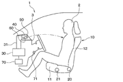
- FIG. 2 is a schematic view of the interior of the vehicle when the seat back is in an upright state in an automobile using the automotive air-conditioning control system according to the first embodiment.
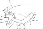
- FIG. 3 is a schematic diagram of the interior of the vehicle when the seat back is in a backward state in an automobile using the automotive air-conditioning control system according to the first embodiment.
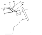
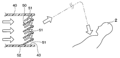
- FIG. 3 is a cross-sectional view around the air outlet according to the first embodiment.
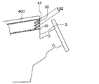
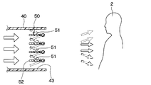
- FIG. 9 is a cross-sectional view around the outlet of Comparative Example 1. It is a mimetic diagram showing the direction of an air-conditioning style blown out from an outlet and an outlet of a 1st embodiment.
- FIG. 11 is a schematic diagram of a vehicle interior when a seat back in a comparative example 2 is in a backward position. It is sectional drawing of the periphery of the outlet of 2nd Embodiment. It is sectional drawing of the periphery of the outlet of 2nd Embodiment.
- FIG. 11 is a schematic diagram of the interior of the vehicle when the seat back is in a backward state in an automobile using the automotive air-conditioning control system according to the third embodiment.
- the vehicle 1 in which the vehicle air-conditioning control system is used includes, in addition to the vehicle in which the occupant 2 performs the driving operation, an automatic driving vehicle in which the automatic driving system performs all the driving operations such as acceleration, steering, braking, and surrounding monitoring.
- an occupant can ride in a state in which the seat back is tilted backward while the vehicle is running (hereinafter, referred to as a "rearward state").
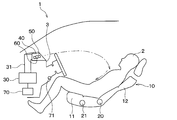
- the automotive air conditioning control system includes a seat 10, an inclination sensor 20, a front / rear position sensor 21, an air conditioner 30, an air outlet 40, a guide fin 50, a fin drive unit 60, a control device 70, and the like.
- a seat 10 an inclination sensor 20, a front / rear position sensor 21, an air conditioner 30, an air outlet 40, a guide fin 50, a fin drive unit 60, a control device 70, and the like.
- the seat 10 is arranged in the vehicle interior.
- the seat 10 is seated on an occupant.
- the seat 10 has a seat cushion 11 that supports the buttocks of the occupant 2 and a seat back 12 that supports the back of the occupant 2.
- the seat back 12 is provided so that the angle with respect to the seat cushion 11 can be changed. Further, the seat 10 is provided so as to be movable in the vehicle front-rear direction with respect to the vehicle cabin floor.
- the tilt sensor 20 is provided on the seat 10.
- the tilt sensor 20 is a seat back state detection unit that detects the state of the seat back 12.
- the tilt sensor 20 detects an angle of the seat back 12 with respect to the seat cushion 11.
- the tilt sensor 20 transmits the detected information to the control device 70.
- Control device 70 determines whether seatback 12 is in the upright state or the backward state based on information transmitted from tilt sensor 20.
- the backward state is a state in which the seat back 12 has fallen rearward of the vehicle from the standing state.
- the front / rear position sensor 21 is provided on the seat 10.
- the front / rear position sensor 21 detects the position of the seat cushion 11 in the vehicle front / rear direction.
- the front / rear position sensor 21 transmits the detected information to the control device 70.
- the air conditioner 30 is arranged inside the instrument panel 3.
- the instrument panel 3 is an entire panel disposed in front of a front seat in a vehicle compartment, including a portion for storing audio and an air conditioner, as well as a portion for disposing instruments.
- the air conditioner 30 generates the conditioned air whose temperature and humidity are adjusted. Specifically, the air conditioner 30 generates conditioned air that is lower in temperature than the vehicle interior air.
- the air conditioner 30 has an air conditioning case.
- a blower, a cooler, a heater, an air mix door, and the like are arranged inside the air conditioning case.
- the blower forms an airflow toward the passenger compartment.
- the cooler cools the air going into the cabin.
- the heater heats the air flowing out of the cooler.
- the air mix door adjusts the mixing ratio of the cool air flowing out of the cooler and the warm air flowing out of the heater. Thereby, the temperature and humidity of the conditioned air flowing into the vehicle cabin are adjusted.
- the outlet 40 is provided in the instrument panel 3.
- the outlet 40 is connected to the air conditioner 30 via a duct 31.
- the outlet 40 blows out the conditioned air generated by the air conditioner 30 into the vehicle interior.
- the outlet 40 of the present embodiment is a face outlet.
- the air outlet 40 blows out the conditioned air mainly toward the upper body of the occupant 2 and its surroundings.
- the automobile 1 is provided with a defroster outlet, a foot outlet, and the like in addition to the face outlet.
- the upper end 41 of the outlet 40 is located on the vehicle front side with respect to the lower end 42 of the outlet 40.
- an outlet 400 of Comparative Example 1 is shown in FIG. 4 for comparison with the outlet 40 of the present embodiment.
- the upper end portion 41 and the lower end portion 42 are located at substantially the same position in the vehicle front-rear direction.
- the substantial opening area S1 of the outlet 40 when the conditioned air is blown upward in the vehicle cabin is larger than the substantial opening area S2 of the outlet 400 of Comparative Example 1. Can be bigger. Thereby, the pressure loss of the conditioned air blown upward from the air outlet 40 into the vehicle cabin can be reduced.
- the guide fin 50 is provided in the internal space of the outlet 40.
- the guide fin 50 is a wind direction variable mechanism that can change the direction of the conditioned air blown from the outlet 40 to an arbitrary vertical direction.
- the fin drive section 60 drives the guide fin 50. Therefore, the fin drive section 60 is a drive section that drives the wind direction variable mechanism.
- the operation of the fin drive unit 60 is controlled by the control device 70.
- the fin drive unit 60 can adjust the direction of the guide fin 50 to an arbitrary position and hold it.
- the guide fin 50 is composed of a plurality of plate members 51.
- Each of the plurality of plate members 51 is vertically arranged with a space therebetween.
- Each of the plurality of plate members 51 is configured such that the angles with respect to the horizontal direction are the same.
- the position of the guide fins 50 is adjusted such that the upstream end 52 of some of the plate members 51 of the plurality of plate members 51 is Can be placed in an upward position that abuts against Some of the plate members 51 are the plate members 51 located at the lowermost side of the plurality of plate members 51.
- the conditioned air is blown toward the upper side in the vehicle cabin more than when the position of the guide fin 50 is the position shown by the broken line in FIG.
- the positioning of the upward position is realized by a part of the plate-like members 51 being in contact with the inner wall 43 of the flow path.
- the positioning of the upward position may be realized by another method.
- the positioning of the upward position may be realized by contacting a part of the plate-shaped members 51 with a structure (not shown) provided in the flow path.
- positioning of the upward position may be realized by a part of the part of the plate-like members 51 different from the end part 53 abutting on the inner wall 43 or the structure of the flow path.
- the guide fins 50 may also be capable of changing the direction of the conditioned air blown from the outlet 40 in the left-right direction.
- the control device 70 is arranged inside the instrument panel 3.
- the control device 70 is composed of a well-known microcomputer including a processor and a memory and its peripheral circuits. Note that the memory of the control device 70 is configured by a non-transitional and substantial storage medium.
- the tilt sensor 20 and the front / rear position sensor 21 are connected to the input side of the control device 70.
- various sensors used for controlling the air conditioner 30 such as an internal air temperature sensor 71 are connected to an input side of the control device 70.
- the inside air temperature sensor 71 detects the temperature of the air inside the vehicle.
- the control device 70 receives vehicle interior environment information such as vehicle interior temperature necessary for controlling the air conditioner 30.
- an operation unit (not shown) of the air conditioner is connected to an input side of the control device 70. When the occupant operates the operation unit, the temperature, air volume, and the like of the conditioned air are set. To the control device 70, setting information such as the temperature and air volume of the conditioned air set by the occupant is input.
- the fin drive unit 60, the blower of the air conditioner 30, the air mix door, and the like are connected to the output side of the control device 70.
- the control device 70 performs various calculations and processes based on a control program stored in the memory. Thereby, the control device 70 controls the operations of the fin drive unit 60 and the blower of the air conditioner 30 based on the detection results of various sensors such as the inclination sensor 20 and the setting information by the operation unit. As a result, the control device 70 controls the direction, temperature, and air volume of the conditioned air blown out from the outlet 40.
- the control device 70 is configured integrally with a control device that controls the air conditioner 30. However, control device 70 may be configured separately from a control device that controls air conditioner 30.
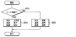
- Control processing executed by the control device 70 of the present embodiment will be described with reference to the flowchart of FIG. 7A.
- This control process is started when the ignition key of the automobile 1 is turned on.
- the automobile 1 is an autonomous vehicle, the operation is started when the traveling switch is turned on. Note that the steps shown in FIG. 7A correspond to functional units that realize various functions.
- step S10 the control device 70 determines whether or not the seat back 12 is in the backward state based on the information transmitted from the inclination sensor 20. Specifically, the control device 70 compares the information on the angle of the seat back 12 transmitted from the inclination sensor 20 with a threshold value stored in advance in the control device 70, and the seat back 12 is in a backward state. It is determined whether or not. When the control device 70 determines that the seat back 12 is not in the backward state (that is, when the determination is NO), the process proceeds to step S20.
- step S20 the control device 70 controls the fin drive unit 60 such that the position of the guide fin 50 is a position arbitrarily set by the occupant.
- the control device 70 does not change the position of the guide fin 50.
- the position of the guide fin 50 is set to a position corresponding to a predetermined portion of the occupant 2.
- the control device 70 changes the position to any position within the range between the broken line position and the dashed line position in FIG. For example, the position of the guide fin 50 in the upright state immediately before the seatback 12 switches from the upright state to the backward state is stored in the memory. The control device 70 changes the position of the guide fin 50 to the position in the upright state.
- the conditioned air blown out from the outlet 40 hits a predetermined portion of the occupant 2.
- the predetermined part of the occupant 2 is the chest.
- the position of the guide fin 50 in FIG. 1 is the position of the solid line in FIG.
- the position of the guide fin 50 can be arbitrarily changed by the operation of the occupant 2.
- control device 70 determines a target temperature and a target air volume of conditioned air blown out from air outlet 40 based on the set temperature, the vehicle interior temperature, and the like.
- the control device 70 controls the operation of the air conditioner 30 so that the temperature and air volume of the conditioned air blown out from the outlet 40 become the determined target temperature and target air volume.
- the control device 70 controls the door position of the air mix door and the air volume of the blower. The temperature and air volume of the conditioned air blown out from the air outlet 40 can be arbitrarily changed by the operation of the occupant 2.
- the direction, temperature, and air volume of the conditioned air blown out from the air outlet 40 are set to an arbitrary direction, an arbitrary temperature, and an arbitrary air volume.
- the conditioned air having an arbitrary temperature and an arbitrary air volume is sent from the air outlet 40 to a predetermined portion of the occupant 2.
- the direction, temperature, and air volume of the conditioned air set when the seat back 12 is in the upright state are referred to as a normal direction, a normal temperature, and a normal air volume.
- the control device 70 determines the blowing mode based on the set temperature, the vehicle interior temperature, and the like.
- the blowing mode include a face mode in which conditioned air is blown out from a face outlet, a defroster mode in which conditioned air is blown out from a defroster outlet, and a foot mode in which conditioned air is blown out from a foot outlet.
- the set temperature is lower than the temperature of the vehicle interior air.
- the blowing mode determined by the control device 70 is the face mode.
- the occupant 2 may select the face mode as the blowing mode.
- step S10 when controller 70 determines that seat back 12 is in the backward state (that is, when YES is determined), control unit 70 proceeds to step S30.
- step S30 the control device 70 controls the fin drive unit 60 such that the position of the guide fin 50 is the upward position shown in FIG.
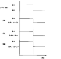
- the direction of the conditioned air blown out from the air outlet 40 is more upward than usual. That is, as shown in FIG. 2, the conditioned air is blown out from the outlet 40.
- the direction of the air-conditioning wind at this time is a direction toward the upper side in the vehicle compartment, as compared with the case where the seat back 12 is in the upright state immediately before switching to the backward state.
- the control device 70 changes the direction of the conditioned air blown out from the outlet 40 to the direction toward the upper side in the vehicle compartment based on the state of the seat back 12 being switched from the standing state to the backward state.
- the fin driving unit 60 is controlled.
- the temperature of the conditioned air is lower than the temperature of the vehicle interior air
- the density of the conditioned air is higher than that of the vehicle interior air.
- the conditioned air blown out toward the upper side of the passenger compartment falls toward the occupant while falling by gravity.
- the direction of the conditioned air flowing toward the occupant while falling is closer to the vertical direction than before the change in the direction of the conditioned air blown out from the outlet 40.
- control device 70 lowers the target temperature of the conditioned air blown out from blowout port 40.
- the control device 70 controls the air conditioner 30 so that the temperature of the conditioned air blown out from the outlet 40 becomes the lowered target temperature.
- the temperature of the conditioned air blown out from the air outlet 40 becomes lower than normal. More specifically, the temperature of the conditioned air blown out from the air outlet 40 is lower than when the seat back 12 is in the standing state immediately before switching to the backward state.
- the control device 70 lowers the temperature of the conditioned air blown out from the outlet 40 based on the switching of the state of the seat back 12 from the standing state to the backward state.
- the density of the conditioned air increases as compared to before the temperature of the conditioned air decreases. For this reason, the difference in density between the conditioned air and the vehicle interior air becomes larger, so that the direction of the conditioned air toward the occupant while falling is closer to the vertical direction.
- control device 70 controls air conditioner 30 so as to reduce the amount of conditioned air blown out from outlet 40.
- control of the air conditioner 30 is to reduce the air volume of the blower.
- the air volume of the conditioned air blown out from the air outlet 40 is smaller than usual. Specifically, the amount of conditioned air blown out from the outlet 40 is reduced as compared with the standing state immediately before the seat back 12 is switched to the backward state. As described above, the control device 70 reduces the amount of the conditioned air blown out from the outlet 40 based on the switching of the state of the seat back 12 from the standing state to the backward state.
- the control device 70 reduces the amount of the conditioned air blown out from the outlet 40.
- the amount of decrease in the air volume at this time is set in advance by an experiment or the like so that even when the seat back 12 is switched to the backward state, the conditioned air is applied to a predetermined portion of the same occupant as in the upright state. 70 is stored in the memory. In other words, the control device 70 reduces the amount of conditioned air blown out from the air outlet so that the conditioned air is applied to the same predetermined part of the occupant as when standing.
- the conditioned air can be applied to the same part of the occupant as when the seat back 12 is in the upright state.
- the control device 70 also determines whether the position of the seat cushion 11 in the vehicle longitudinal direction has been changed based on information transmitted from the longitudinal position sensor 21.
- control device 70 adjusts the amount of conditioned air blown out from the outlet according to the position of seat cushion 11.
- the adjustment amount of the air volume at this time is set in advance by an experiment or the like so that the conditioned air is applied to a predetermined portion of the occupant in the same state as in the standing state, and is stored in the memory of the control device 70.
- the conditioned air is applied to the same part of the occupant as when the seat back 12 was standing up. be able to.
- Comparative Example 2 corresponds to the case where the above-described combination device blows wind from the face outlet toward the occupant's chest when the seatback is in the backward state.
- the position of the guide fins 50 when the seat back 12 is in the backward position is the position where the wind is blown straight out from the outlet 40 toward the occupant's 2 chest.
- the linear shape means a state close to a straight line.
- the outlet is located at a lower position than in the device of Patent Document 1 described above. Furthermore, in Comparative Example 2, the direction of the conditioned air blown out from the air outlet 40 when the seat back 12 is in the backward state is a direction toward the lower side than when the seat back 12 is in the upright state. For this reason, when the seat back 12 is in the backward position, as shown in FIG. 8, the conditioned air blown out from the outlet 40 reaches the chest of the occupant 2 and then moves downward along the body of the occupant 2. Flows upward from. This may cause the occupant 2 to feel uncomfortable as described above.
- the conditioned air blown out from the air outlet 40 toward the occupant 2 is blown out from the air outlet 40 toward the upper side of the passenger compartment, so that The wind is like falling from above. Thereby, it is possible to suppress the occupant 2 from feeling uncomfortable.
- the conditioned air is blown to the chest of the occupant 2.
- the conditioned air may be applied to a predetermined portion other than the chest of the occupant 2. Examples of the predetermined portion other than the chest include a neck, an abdomen, and a thigh.
- the control device 70 controls the guide fins 50 and the air conditioning The device 30 is controlled.
- the control device 70 may control the guide fins 50 and the air conditioner 30 so as to blow the conditioned air to a part of the occupant different from that in the standing state.
- the reduction amount of the air flow when the control device 70 reduces the air flow of the conditioned air may be set so that the conditioned air is applied to the occupant 2 when the seat back 12 is switched to the backward state. . Thereby, even if the seat back 12 is in the backward state, the conditioned air of the occupant 2 can be blown to the predetermined portion.
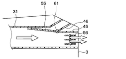
- the automotive air-conditioning control system includes a face outlet 45, a dedicated outlet 46, a switching door 55, and a door driving unit 61.
- the face outlet 45 corresponds to the outlet 40 of the first embodiment.
- Guide fins 56 are arranged in the internal space of the face outlet 45.
- the guide fins 56 change the direction of the conditioned air blown from the outlet 40 in the vertical direction, similarly to the guide fins 50 of the first embodiment.
- the range in which the guide fins 56 change the direction of the conditioned air does not include the direction of the conditioned air shown in FIG.
- the dedicated outlet 46 is provided above the face outlet 45 in the instrument panel 3.
- the dedicated outlet 46 is connected to the duct 31 that connects the air conditioner 30 and the face outlet 45.
- the dedicated air outlet 46 blows out the conditioned air toward the upper side of the vehicle interior than the face air outlet 45.
- the switching door 55 is disposed on the upstream side of the face outlet 45 and the dedicated outlet 46 in the duct 31.
- the switching door 55 switches between the airflow of the conditioned air generated by the air conditioner 30 toward the face outlet 45 and the airflow of the conditioned air generated by the air conditioner 30 toward the dedicated air outlet 46.
- the door driving unit 61 drives the switching door 55.
- the operation of the door drive unit 61 is controlled by the control device 70.
- the face air outlet 45 and the dedicated air outlet 46 are provided in the instrument panel 3 and correspond to air outlets for blowing the conditioned air generated by the air conditioner into the vehicle interior.
- the switching door 55 corresponds to a wind direction variable mechanism that can change the direction of the conditioned air blown out from the outlet in the up-down direction.
- the door drive unit 61 corresponds to a drive unit that drives the wind direction variable mechanism.
- control processing executed by the control device 70 of the first embodiment is changed as follows.
- step S20 the control device 70 sets the position of the switching door 55 to the position where the conditioned air generated by the air conditioner 30 goes to the face outlet 45 as shown in FIG.
- the conditioned air is blown from the face outlet 45 toward the upper body of the occupant 2.
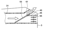
- step S30 the control device 70 controls the door driving unit 61 so that the position of the switching door 55 is set to the position where the conditioned air generated by the air conditioner 30 is directed to the dedicated outlet 46 as shown in FIG. Control.
- the control device 70 controls the fin drive unit 60 so that the direction of the conditioned air blown out from the outlet changes to the direction toward the upper side in the vehicle interior.
- control process The other parts of the control process are the same as those of the first embodiment. Therefore, also in the present embodiment, the same effect as in the first embodiment can be obtained. Further, according to the present embodiment, the following effects can be obtained.
- the pressure loss of the conditioned air by the guide fins 56 of the face outlet 45 is eliminated by blowing the conditioned air from the dedicated outlet 46. Therefore, the conditioned air blown out from the dedicated air outlet 46 can be efficiently delivered to the occupant 2.
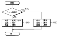
- step S30 in FIG. 7A is changed to step S40.
- step S40 the control device 70 does not change the direction of the conditioned air blown out from the outlet 40 from the normal direction.
- the control device 70 lowers the target temperature of the conditioned air blown out from the outlet 40.
- the control device 70 controls the air conditioner 30 so that the temperature of the conditioned air blown out from the outlet 40 becomes the lowered target temperature.
- the temperature of the conditioned air blown out from the outlet 40 is lower than usual. More specifically, the temperature of the conditioned air blown out from the air outlet 40 is lower than when the seat back 12 is in the standing state immediately before switching to the backward state. As described above, the control device 70 lowers the temperature of the conditioned air blown out from the outlet 40 based on the switching of the state of the seat back 12 from the standing state to the backward state.
- the temperature of the conditioned air generated by the air conditioner 30 is lower than the temperature of the vehicle interior air. Therefore, the conditioned air has a higher density than the vehicle interior air. Further, the temperature of the conditioned air blown from the outlet 40 is reduced by step S40. Thereby, the density of the conditioned air is further increased. Therefore, as shown in FIG. 12, the conditioned air blown out from the outlet 40 is directed toward the occupant while falling by gravity. The direction of the conditioned air heading toward the occupant while falling is closer to the vertical direction than before the temperature of the conditioned air is lowered. Therefore, according to the present embodiment, the same effect as that of the first embodiment can be obtained.
- control device 70 controls air conditioner 30 so as to increase the amount of conditioned air blown out from outlet 40.
- the control of the air conditioner 30 is, specifically, to increase the air volume of the blower.
- the control device 70 increases the amount of the conditioned air blown out from the outlet 40 based on the switching of the state of the seat back 12 from the standing state to the backward state.
- control device 70 increases the amount of the conditioned air blown out of the outlet 40.
- the amount of increase in the air volume at this time is set in advance by an experiment or the like so that even when the seat back 12 is switched to the backward state, the conditioned air is applied to a predetermined portion of the same occupant as in the upright state. 70 is stored in the memory. In other words, control device 70 increases the flow rate of the conditioned air blown out from the outlet so that the conditioned air blows on the same part of occupant 2 as when seatback 12 is in the upright state.
- the conditioned air can be applied to the same portion as when the seat back 12 is in the upright state.
- the control device 70 may increase the amount of the conditioned air so as to blow the conditioned air to a part of the occupant different from that in the upright state. .
- the amount of increase in the airflow is set so that the conditioned air is blown against the occupant 2 when the seat back 12 is switched to the backward state. Thereby, even if the seat back 12 is in the backward state, the conditioned air of the occupant 2 can be blown to the predetermined portion.
- step S30 of the control processing according to the first embodiment the control device 70 controls the fin drive unit 60 so that the position of the guide fin 50 is the upward position shown in FIG.
- the position of the guide fins 50 at this time may not be the upward position shown in FIG. 6 as long as the direction of the conditioned air blown out from the outlet 40 changes to the upward direction in the vehicle interior.
- the control device 70 may change the position of the guide fin 50 to the broken line position in FIG. Further, when the position of the guide fin 50 in the upright state is the position indicated by the one-dot chain line in FIG. 5, the control device 70 may change the position of the guide fin 50 to the solid line position in FIG. As described above, the control device 70 changes the direction of the conditioned air blown out from the outlet 40 to the direction toward the upper side in the vehicle compartment based on the state of the seat back 12 being switched from the standing state to the backward state. Thus, the fin drive unit 60 may be controlled.
- the direction of the conditioned air blown out from the air outlet 40 is the same as the direction toward the upper side of the vehicle compartment as compared with the standing state immediately before switching to the backward state. Become. Then, since the temperature of the conditioned air is lower than the temperature of the cabin air, the conditioned air blown out toward the upper side of the cabin goes toward the occupant while falling by gravity. The direction of the conditioned air flowing toward the occupant while falling is closer to the vertical direction than before the change in the direction of the conditioned air blown out from the outlet 40. Therefore, the same effect as in the first embodiment can be obtained.
- the inclination sensor 20 is used as the seat back state detection unit.
- a rotation angle sensor that detects the rotation angle of a motor that moves the seat back 12
- an in-vehicle camera that images the seat 10 or the occupant 2 on the seat 10 may be used as the seat back state detection unit.
- the control device 70 compares the information transmitted from the rotation angle sensor with a threshold value stored in advance in the control device 70 in step S10 of the control processing of the first embodiment, It is determined whether or not the seat back 12 is in the backward state.
- control device 70 analyzes the image captured by the in-vehicle camera in step S10 of the control processing of the first embodiment, and determines whether or not the seat back 12 is in a backward state. Is determined.
- the sleep switch may be used as the seat back state detecting unit. In this case, is transmitted to the control device 70.
- the control device 70 determines whether or not the seat back 12 is in the backward state based on the information on whether or not the sleep switch transmitted from the sleep switch is turned on.
- the control device 70 sets the target temperature of the conditioned air blown from the outlet 40 in order to reduce the temperature of the conditioned air blown from the outlet 40. Had been lowered. However, the control device 70 may operate the cooling device provided in the duct 31 instead of lowering the target temperature of the conditioned air.
- step S30 the control device 70 reduces the air volume of the blower in order to reduce the air volume of the conditioned air blown out from the air outlet 40.
- the control device 70 may lower the air distribution ratio of the air outlet 40 by moving the air outlet mode door that switches the air outlet mode of the air conditioner 30 instead of reducing the air volume of the blower.
- the control device 70 may narrow the opening of the outlet 40 by the opening adjusting mechanism.
- step S40 the control device 70 increases the air volume of the blower in order to increase the air volume of the conditioned air blown out from the air outlet 40.
- the control device 70 may increase the air distribution ratio of the air outlet 40 by moving the air outlet mode door that switches the air outlet mode of the air conditioner 30 instead of increasing the air volume of the blower.
- the controller 70 may widen the opening of the outlet 40 by the opening adjusting mechanism.
- the present disclosure is applied to a general face outlet.
- the present disclosure can be applied to an outlet different from a general face outlet as long as the outlet is an outlet provided in the instrument panel and blows conditioned air toward an occupant. is there.
- an air conditioning control system for a vehicle includes a seat disposed in a vehicle interior and an air conditioning system that generates conditioned air that is lower in temperature than the vehicle interior air.
- Device an air outlet provided on the instrument panel, for blowing air-conditioned air into the vehicle interior, a variable air direction mechanism capable of changing the direction of the air-conditioned air blown from the air outlet in the vertical direction, and a drive unit for driving the variable air direction mechanism
- a detection unit that detects a state of a seat back of the seat; and a control device that controls the driving unit based on a detection result of the detection unit.
- the control device controls the drive unit so that the direction of the conditioned air blown out from the outlet changes to the direction toward the upper side of the vehicle compartment based on the switching of the seat back state from the standing state to the backward state.
- control device changes the temperature of the conditioned air blown out from the outlet based on the fact that the state of the seat back has been switched from the standing state to the backward state. Lower.
- the temperature of the conditioned air blown out from the outlet decreases.
- the density of the conditioned air increases as compared to before the temperature of the conditioned air decreases. For this reason, the difference in density between the conditioned air and the vehicle interior air becomes larger, so that the direction of the conditioned air toward the occupant while falling is closer to the vertical direction.
- the wind blown out from the air outlet can be further suppressed from flowing upward along the occupant's body after reaching the occupant's predetermined portion. it can.
- control device may control the air-conditioning air blown out from the air outlet based on the fact that the state of the seat back is switched from the upright state to the backward state. To reduce the air volume.
- the control device is blown out from the outlet. Reduce the volume of air-conditioning air. Thereby, even if the seat back is in a backward state, air conditioning air can be blown to a predetermined part of the occupant.
- control device reduces the amount of conditioned air blown out from the air outlet so that the conditioned air blows to the same predetermined portion of the occupant as when standing. Thereby, even if the seat back is in the backward state, the conditioned air can be applied to the same predetermined portion of the occupant as when the seat back is in the upright state.
- an automotive air conditioning control system in an instrument panel, a seat disposed in a vehicle interior, an air conditioner that generates conditioned air that is lower in temperature than the vehicle interior air, An outlet for blowing the wind into the vehicle interior, a detecting unit for detecting a state of a seat back of the seat, and a control device for controlling the temperature of the conditioned air blown from the outlet based on a detection result of the detecting unit.
- the control device lowers the temperature of the conditioned air blown out from the air outlet based on the switching of the seat back state from the upright state to the backward state.
- control device changes the amount of air-conditioned air blown out from the outlet based on the fact that the state of the seat back has been switched from the standing state to the backward state. Increase.
- the control device increases the amount of conditioned air blown out from the outlet. Thereby, even if the seat back is in a backward state, air conditioning air can be blown to a predetermined part of the occupant.
- control device increases the amount of the conditioned air blown out from the air outlet so that the conditioned air is blown against the occupant at the same position as when the seat back is in the upright state. Thereby, even if the seat back is in the backward state, the air conditioning air can be applied to the same portion as when the seat back is in the upright state.
- the control device is used for air conditioning of an automobile.
- This vehicle has a seat disposed in a vehicle interior, an air conditioner that generates conditioned air that is lower in temperature than the vehicle interior air, an air outlet provided on an instrument panel, and an air outlet that blows the air conditioned air into the vehicle interior, and an air outlet.
- the air conditioner includes a wind direction variable mechanism that can change the direction of the conditioned air to be blown up and down, a drive unit that drives the wind direction variable mechanism, and a detection unit that detects the state of the seat back of the seat.
- the control device controls the drive unit so that the direction of the conditioned air blown out from the outlet changes to the direction toward the upper side of the vehicle compartment based on the switching of the seat back state from the standing state to the backward state. I do.
- the control device is used for air conditioning of an automobile.
- This vehicle has a seat disposed in a vehicle interior, an air conditioner that generates conditioned air that is lower in temperature than the vehicle interior air, an air outlet that is provided in an instrument panel and blows out the conditioned air into the vehicle interior, and a seat.
- a detection unit that detects a state of the seat back. The control device lowers the temperature of the conditioned air blown out from the air outlet based on the switching of the seat back state from the upright state to the backward state.
Landscapes
- Physics & Mathematics (AREA)
- Thermal Sciences (AREA)
- Engineering & Computer Science (AREA)
- Mechanical Engineering (AREA)
- Air-Conditioning For Vehicles (AREA)
Priority Applications (1)
| Application Number | Priority Date | Filing Date | Title |
|---|---|---|---|
| US17/215,989 US20210213801A1 (en) | 2018-10-04 | 2021-03-29 | Air conditioning control system and control device for vehicle |
Applications Claiming Priority (2)
| Application Number | Priority Date | Filing Date | Title |
|---|---|---|---|
| JP2018-189328 | 2018-10-04 | ||
| JP2018189328A JP2020055501A (ja) | 2018-10-04 | 2018-10-04 | 自動車用空調制御システムおよび制御装置 |
Related Child Applications (1)
| Application Number | Title | Priority Date | Filing Date |
|---|---|---|---|
| US17/215,989 Continuation US20210213801A1 (en) | 2018-10-04 | 2021-03-29 | Air conditioning control system and control device for vehicle |
Publications (1)
| Publication Number | Publication Date |
|---|---|
| WO2020071248A1 true WO2020071248A1 (ja) | 2020-04-09 |
Family
ID=70054477
Family Applications (1)
| Application Number | Title | Priority Date | Filing Date |
|---|---|---|---|
| PCT/JP2019/037979 Ceased WO2020071248A1 (ja) | 2018-10-04 | 2019-09-26 | 自動車用空調制御システムおよび制御装置 |
Country Status (3)
| Country | Link |
|---|---|
| US (1) | US20210213801A1 (enExample) |
| JP (1) | JP2020055501A (enExample) |
| WO (1) | WO2020071248A1 (enExample) |
Families Citing this family (3)
| Publication number | Priority date | Publication date | Assignee | Title |
|---|---|---|---|---|
| JP7135555B2 (ja) * | 2018-08-06 | 2022-09-13 | 株式会社デンソー | 自動車用空調制御システム、自動車用空調システム、制御装置 |
| CN111572308A (zh) * | 2020-04-29 | 2020-08-25 | 延锋汽车饰件系统有限公司 | 汽车座舱及其温度控制方法、系统、设备和存储介质 |
| FR3159217A1 (fr) * | 2024-02-13 | 2025-08-15 | Stellantis Auto Sas | Procede de contrôle d’un systeme d’aeration de vehicule automobile avec aerateurs orientables motorises |
Citations (8)
| Publication number | Priority date | Publication date | Assignee | Title |
|---|---|---|---|---|
| JPS58133913A (ja) * | 1982-02-01 | 1983-08-09 | Nippon Denso Co Ltd | カ−エアコン制御装置 |
| JPS63243650A (ja) * | 1987-03-30 | 1988-10-11 | Matsushita Electric Ind Co Ltd | 空気調和機の風向偏向装置 |
| JPH03230043A (ja) * | 1990-02-05 | 1991-10-14 | Matsushita Electric Ind Co Ltd | 空気調和機の制御装置 |
| DE4229596A1 (de) * | 1992-09-04 | 1994-03-10 | Bayerische Motoren Werke Ag | Belüftungsanordnung für einen Fahrzeug-Innenraum |
| JP2007285562A (ja) * | 2006-04-14 | 2007-11-01 | Matsushita Electric Ind Co Ltd | 空気調和機の制御装置 |
| JP2015232421A (ja) * | 2014-06-10 | 2015-12-24 | 日立アプライアンス株式会社 | 空気調和機 |
| US20170101032A1 (en) * | 2015-10-07 | 2017-04-13 | Volvo Car Corporation | Seat system for autonomous vehicles |
| JP2018131196A (ja) * | 2017-02-14 | 2018-08-23 | 株式会社デンソー | 車両用空調ユニット |
Family Cites Families (1)
| Publication number | Priority date | Publication date | Assignee | Title |
|---|---|---|---|---|
| JP2006264485A (ja) * | 2005-03-23 | 2006-10-05 | Denso Corp | 車両用空調装置 |
-
2018
- 2018-10-04 JP JP2018189328A patent/JP2020055501A/ja active Pending
-
2019
- 2019-09-26 WO PCT/JP2019/037979 patent/WO2020071248A1/ja not_active Ceased
-
2021
- 2021-03-29 US US17/215,989 patent/US20210213801A1/en not_active Abandoned
Patent Citations (8)
| Publication number | Priority date | Publication date | Assignee | Title |
|---|---|---|---|---|
| JPS58133913A (ja) * | 1982-02-01 | 1983-08-09 | Nippon Denso Co Ltd | カ−エアコン制御装置 |
| JPS63243650A (ja) * | 1987-03-30 | 1988-10-11 | Matsushita Electric Ind Co Ltd | 空気調和機の風向偏向装置 |
| JPH03230043A (ja) * | 1990-02-05 | 1991-10-14 | Matsushita Electric Ind Co Ltd | 空気調和機の制御装置 |
| DE4229596A1 (de) * | 1992-09-04 | 1994-03-10 | Bayerische Motoren Werke Ag | Belüftungsanordnung für einen Fahrzeug-Innenraum |
| JP2007285562A (ja) * | 2006-04-14 | 2007-11-01 | Matsushita Electric Ind Co Ltd | 空気調和機の制御装置 |
| JP2015232421A (ja) * | 2014-06-10 | 2015-12-24 | 日立アプライアンス株式会社 | 空気調和機 |
| US20170101032A1 (en) * | 2015-10-07 | 2017-04-13 | Volvo Car Corporation | Seat system for autonomous vehicles |
| JP2018131196A (ja) * | 2017-02-14 | 2018-08-23 | 株式会社デンソー | 車両用空調ユニット |
Also Published As
| Publication number | Publication date |
|---|---|
| US20210213801A1 (en) | 2021-07-15 |
| JP2020055501A (ja) | 2020-04-09 |
Similar Documents
| Publication | Publication Date | Title |
|---|---|---|
| US20190359028A1 (en) | Vehicle air conditioning unit | |
| JP4348847B2 (ja) | 車両用空調装置およびその制御方法 | |
| JP6658679B2 (ja) | シート空調装置 | |
| JP7020943B2 (ja) | 車両用空調装置 | |
| US20120129439A1 (en) | Air conditioning system for vehicle | |
| JP7135555B2 (ja) | 自動車用空調制御システム、自動車用空調システム、制御装置 | |
| US20210213801A1 (en) | Air conditioning control system and control device for vehicle | |
| WO2020108856A1 (en) | A vehicle system | |
| JP2020029180A (ja) | 車載装置、車載装置の制御方法、車載装置の制御プログラム及び車両用シートの表面温度調節方法 | |
| JP2006160024A (ja) | 車両用空調装置および車両用空調制御方法 | |
| CN112638675B (zh) | 汽车用空调系统、控制装置 | |
| JP4935515B2 (ja) | 車両用空調装置 | |
| US11247531B2 (en) | Vehicle air conditioning unit | |
| JP4613718B2 (ja) | 車両用空調装置および車両用空調制御方法 | |
| JP7031337B2 (ja) | 車両用空調装置 | |
| US11052727B2 (en) | Vehicle air-conditioning device | |
| JP7031279B2 (ja) | 車両用空調装置 | |
| JPH11189023A (ja) | 車両用空調装置 | |
| JP7064716B2 (ja) | 車両用空調制御装置 | |
| JP7309324B2 (ja) | 車両空調システム | |
| JP6658898B2 (ja) | 車両用空調装置 | |
| WO2018150805A1 (ja) | 車両用空調ユニット | |
| JP2019127096A (ja) | 空調システム | |
| JP2006232007A (ja) | 車両用空調装置 | |
| JP2025018166A (ja) | 車載空調制御装置、該方法および該プログラム |
Legal Events
| Date | Code | Title | Description |
|---|---|---|---|
| 121 | Ep: the epo has been informed by wipo that ep was designated in this application |
Ref document number: 19868555 Country of ref document: EP Kind code of ref document: A1 |
|
| NENP | Non-entry into the national phase |
Ref country code: DE |
|
| 122 | Ep: pct application non-entry in european phase |
Ref document number: 19868555 Country of ref document: EP Kind code of ref document: A1 |