WO2020071248A1 - Automobile air-conditioning control system and control device - Google Patents
Automobile air-conditioning control system and control deviceInfo
- Publication number
- WO2020071248A1 WO2020071248A1 PCT/JP2019/037979 JP2019037979W WO2020071248A1 WO 2020071248 A1 WO2020071248 A1 WO 2020071248A1 JP 2019037979 W JP2019037979 W JP 2019037979W WO 2020071248 A1 WO2020071248 A1 WO 2020071248A1
- Authority
- WO
- WIPO (PCT)
- Prior art keywords
- air
- outlet
- state
- conditioned air
- control device
- Prior art date
Links
Images

Classifications
-
- B—PERFORMING OPERATIONS; TRANSPORTING
- B60—VEHICLES IN GENERAL
- B60H—ARRANGEMENTS OF HEATING, COOLING, VENTILATING OR OTHER AIR-TREATING DEVICES SPECIALLY ADAPTED FOR PASSENGER OR GOODS SPACES OF VEHICLES
- B60H1/00—Heating, cooling or ventilating [HVAC] devices
- B60H1/00642—Control systems or circuits; Control members or indication devices for heating, cooling or ventilating devices
- B60H1/00735—Control systems or circuits characterised by their input, i.e. by the detection, measurement or calculation of particular conditions, e.g. signal treatment, dynamic models
- B60H1/00792—Arrangement of detectors
-
- B—PERFORMING OPERATIONS; TRANSPORTING
- B60—VEHICLES IN GENERAL
- B60H—ARRANGEMENTS OF HEATING, COOLING, VENTILATING OR OTHER AIR-TREATING DEVICES SPECIALLY ADAPTED FOR PASSENGER OR GOODS SPACES OF VEHICLES
- B60H1/00—Heating, cooling or ventilating [HVAC] devices
- B60H1/00642—Control systems or circuits; Control members or indication devices for heating, cooling or ventilating devices
- B60H1/00735—Control systems or circuits characterised by their input, i.e. by the detection, measurement or calculation of particular conditions, e.g. signal treatment, dynamic models
- B60H1/00742—Control systems or circuits characterised by their input, i.e. by the detection, measurement or calculation of particular conditions, e.g. signal treatment, dynamic models by detection of the vehicle occupants' presence; by detection of conditions relating to the body of occupants, e.g. using radiant heat detectors
-
- B—PERFORMING OPERATIONS; TRANSPORTING
- B60—VEHICLES IN GENERAL
- B60H—ARRANGEMENTS OF HEATING, COOLING, VENTILATING OR OTHER AIR-TREATING DEVICES SPECIALLY ADAPTED FOR PASSENGER OR GOODS SPACES OF VEHICLES
- B60H1/00—Heating, cooling or ventilating [HVAC] devices
- B60H1/00642—Control systems or circuits; Control members or indication devices for heating, cooling or ventilating devices
- B60H1/00814—Control systems or circuits characterised by their output, for controlling particular components of the heating, cooling or ventilating installation
- B60H1/00821—Control systems or circuits characterised by their output, for controlling particular components of the heating, cooling or ventilating installation the components being ventilating, air admitting or air distributing devices
- B60H1/00828—Ventilators, e.g. speed control
-
- B—PERFORMING OPERATIONS; TRANSPORTING
- B60—VEHICLES IN GENERAL
- B60H—ARRANGEMENTS OF HEATING, COOLING, VENTILATING OR OTHER AIR-TREATING DEVICES SPECIALLY ADAPTED FOR PASSENGER OR GOODS SPACES OF VEHICLES
- B60H1/00—Heating, cooling or ventilating [HVAC] devices
- B60H1/00642—Control systems or circuits; Control members or indication devices for heating, cooling or ventilating devices
- B60H1/00814—Control systems or circuits characterised by their output, for controlling particular components of the heating, cooling or ventilating installation
- B60H1/00821—Control systems or circuits characterised by their output, for controlling particular components of the heating, cooling or ventilating installation the components being ventilating, air admitting or air distributing devices
- B60H1/00871—Air directing means, e.g. blades in an air outlet
-
- B—PERFORMING OPERATIONS; TRANSPORTING
- B60—VEHICLES IN GENERAL
- B60H—ARRANGEMENTS OF HEATING, COOLING, VENTILATING OR OTHER AIR-TREATING DEVICES SPECIALLY ADAPTED FOR PASSENGER OR GOODS SPACES OF VEHICLES
- B60H1/00—Heating, cooling or ventilating [HVAC] devices
- B60H1/24—Devices purely for ventilating or where the heating or cooling is irrelevant
- B60H1/241—Devices purely for ventilating or where the heating or cooling is irrelevant characterised by the location of ventilation devices in the vehicle
- B60H1/242—Devices purely for ventilating or where the heating or cooling is irrelevant characterised by the location of ventilation devices in the vehicle located in the front area
Definitions
- the present disclosure relates to a vehicle air conditioning control system and a control device.
- Patent Literature 1 discloses that a direction of an air outlet of an air blower provided in a rearview mirror of an automobile is changed according to an angle of a seatback detected by a position sensor, so that a predetermined occupant of the occupant is independent of the angle of the seatback. What blows wind to a part is described.
- a wind is blown out from a face outlet provided in an instrument panel (hereinafter referred to as an instrument panel) toward the upper body of the occupant.
- an instrument panel hereinafter, referred to as an instrument panel
- the direction of the wind blown out from the face outlet is determined by a sheet. It will vary according to the angle of the back.
- the device of Patent Document 1 when considering blowing the wind to the occupant's chest regardless of the angle of the seat back, the device of Patent Document 1 has a state in which the seat back falls down rearward because the position of the air outlet is high near the ceiling (Hereinafter referred to as "rearward state"), it is easy to blow the wind to the occupant's chest.
- the device of Patent Literature 1 has a problem that a duct must be taken from an air conditioner arranged inside the instrument panel to a ceiling, or a blower must be installed separately from a blower included in the air conditioner. There is.
- the above problem does not occur since the face outlet is provided in the instrument panel.
- the outlet is located at a lower position than the device of Patent Document 1.
- the direction of the wind blown out from the face outlet is the direction in which the wind is blown straight out from the face outlet toward the occupant's chest. For this reason, the wind blown out from the face outlet reaches the chest of the occupant and then flows from the lower side to the upper side along the occupant's body.
- the occupant may feel uncomfortable. For example, if the occupant is not accustomed to the wind that has reached the occupant flowing upward along the occupant's body, the occupant feels uncomfortable with the flow of the wind. Further, when the occupant wants to avoid the wind from reaching the face, the occupant feels uncomfortable with the wind reaching the chest of the occupant reaching the face. Further, the wind that has reached the occupant flows along the occupant's body, so that the temperature of the wind changes according to the occupant's body temperature. Therefore, the occupant feels uncomfortable when the temperature of the wind reaching the occupant's face is different from the temperature of the wind blown out from the outlet.
- the present disclosure is directed to an automotive air conditioner that can suppress the wind blown from an air outlet from flowing upward along an occupant's body after reaching a predetermined portion of the occupant when the seat back is in a backward state. It is an object to provide a control system and a control device.
- Automotive air conditioning control systems A seat placed in the passenger compartment, An air conditioner that generates conditioned air that is lower in temperature than the cabin air; An outlet provided on the instrument panel for blowing air-conditioned air into the vehicle interior; A wind direction variable mechanism that can change the direction of the conditioned air blown out from the outlet in a vertical direction, A drive unit for driving the wind direction variable mechanism, A detection unit that detects a state of a seat back of the seat, A control device that controls the drive unit based on the detection result of the detection unit, The control device controls the drive unit so that the direction of the conditioned air blown out from the outlet changes to the direction toward the upper side of the vehicle compartment based on the switching of the seat back state from the standing state to the backward state. I do.
- the direction of the conditioned air blown out from the outlet changes to the direction toward the upper side in the vehicle interior.
- the conditioned air has a higher density than the vehicle interior air.
- the conditioned air blown out toward the upper side of the passenger compartment falls toward the occupant while falling by gravity.
- the direction of the conditioned air flowing toward the occupant while falling is closer to the vertical direction than before the change in the direction of the conditioned air blown out from the outlet.
- the conditioned air blown out from the air outlet toward the occupant is blown out from the air outlet toward the upper side of the vehicle interior, so that the conditioned air flows downward from above toward the occupant.
- the wind blown out from the outlet can be suppressed from flowing upward along the occupant's body after reaching the occupant's predetermined portion.
- Automotive air conditioning control systems A seat placed in the passenger compartment, An air conditioner that generates conditioned air that is lower in temperature than the cabin air; An outlet provided on the instrument panel for blowing air-conditioned air into the vehicle interior; A detection unit that detects a state of a seat back of the seat, A control device that controls the drive unit based on the detection result of the detection unit, The control device lowers the temperature of the conditioned air blown out from the air outlet based on the switching of the seat back state from the upright state to the backward state.
- the conditioned air since the temperature of the conditioned air generated by the air conditioner is lower than the temperature of the vehicle interior air, the conditioned air has a higher density than the vehicle interior air. Further, when the state of the seat back is switched from the standing state to the backward state, the temperature of the conditioned air blown out from the outlet decreases. Thereby, the density of the conditioned air is further increased. For this reason, the conditioned air blown out from the outlet exits toward the occupant while falling by gravity. The direction of the conditioned air heading toward the occupant while falling is closer to the vertical direction than before the temperature of the conditioned air is lowered. As a result, when the seat back is in the backward state, the wind blown out from the outlet can be suppressed from flowing upward along the occupant's body after reaching the occupant's predetermined portion.
- the control device is used for air conditioning of an automobile.
- This vehicle has a seat disposed in a vehicle interior, an air conditioner that generates conditioned air that is lower in temperature than the vehicle interior air, an air outlet provided on an instrument panel, and an air outlet that blows the air conditioned air into the vehicle interior, and an air outlet.
- the air conditioner includes a wind direction variable mechanism that can change the direction of the conditioned air to be blown up and down, a drive unit that drives the wind direction variable mechanism, and a detection unit that detects the state of the seat back of the seat.
- control device is configured to change the direction of the conditioned air blown from the air outlet to the direction toward the upper side of the vehicle interior based on the switching of the seat back state from the standing state to the backward state. Control. According to this, the same effect as the above-described vehicle air conditioning control system of one aspect can be obtained.
- the control device is used for air conditioning of an automobile.
- This vehicle has a seat disposed in a vehicle interior, an air conditioner that generates conditioned air that is lower in temperature than the vehicle interior air, an air outlet that is provided in an instrument panel and blows out the conditioned air into the vehicle interior, and a seat.
- a detection unit that detects a state of the seat back.
- the control device lowers the temperature of the conditioned air blown out from the outlet based on the fact that the state of the seat back is switched from the upright state to the backward state. According to this, the same effect as the above-described vehicle air conditioning control system of another aspect can be obtained.
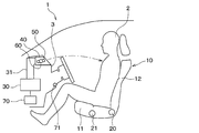
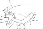
- FIG. 2 is a schematic view of the interior of the vehicle when the seat back is in an upright state in an automobile using the automotive air-conditioning control system according to the first embodiment.
- FIG. 3 is a schematic diagram of the interior of the vehicle when the seat back is in a backward state in an automobile using the automotive air-conditioning control system according to the first embodiment.
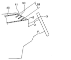
- FIG. 3 is a cross-sectional view around the air outlet according to the first embodiment.
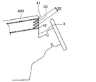
- FIG. 9 is a cross-sectional view around the outlet of Comparative Example 1. It is a mimetic diagram showing the direction of an air-conditioning style blown out from an outlet and an outlet of a 1st embodiment.
- FIG. 11 is a schematic diagram of a vehicle interior when a seat back in a comparative example 2 is in a backward position. It is sectional drawing of the periphery of the outlet of 2nd Embodiment. It is sectional drawing of the periphery of the outlet of 2nd Embodiment.
- FIG. 11 is a schematic diagram of the interior of the vehicle when the seat back is in a backward state in an automobile using the automotive air-conditioning control system according to the third embodiment.
- the vehicle 1 in which the vehicle air-conditioning control system is used includes, in addition to the vehicle in which the occupant 2 performs the driving operation, an automatic driving vehicle in which the automatic driving system performs all the driving operations such as acceleration, steering, braking, and surrounding monitoring.
- an occupant can ride in a state in which the seat back is tilted backward while the vehicle is running (hereinafter, referred to as a "rearward state").
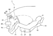
- the automotive air conditioning control system includes a seat 10, an inclination sensor 20, a front / rear position sensor 21, an air conditioner 30, an air outlet 40, a guide fin 50, a fin drive unit 60, a control device 70, and the like.
- a seat 10 an inclination sensor 20, a front / rear position sensor 21, an air conditioner 30, an air outlet 40, a guide fin 50, a fin drive unit 60, a control device 70, and the like.
- the seat 10 is arranged in the vehicle interior.
- the seat 10 is seated on an occupant.
- the seat 10 has a seat cushion 11 that supports the buttocks of the occupant 2 and a seat back 12 that supports the back of the occupant 2.
- the seat back 12 is provided so that the angle with respect to the seat cushion 11 can be changed. Further, the seat 10 is provided so as to be movable in the vehicle front-rear direction with respect to the vehicle cabin floor.
- the tilt sensor 20 is provided on the seat 10.
- the tilt sensor 20 is a seat back state detection unit that detects the state of the seat back 12.
- the tilt sensor 20 detects an angle of the seat back 12 with respect to the seat cushion 11.
- the tilt sensor 20 transmits the detected information to the control device 70.
- Control device 70 determines whether seatback 12 is in the upright state or the backward state based on information transmitted from tilt sensor 20.
- the backward state is a state in which the seat back 12 has fallen rearward of the vehicle from the standing state.
- the front / rear position sensor 21 is provided on the seat 10.
- the front / rear position sensor 21 detects the position of the seat cushion 11 in the vehicle front / rear direction.
- the front / rear position sensor 21 transmits the detected information to the control device 70.
- the air conditioner 30 is arranged inside the instrument panel 3.
- the instrument panel 3 is an entire panel disposed in front of a front seat in a vehicle compartment, including a portion for storing audio and an air conditioner, as well as a portion for disposing instruments.
- the air conditioner 30 generates the conditioned air whose temperature and humidity are adjusted. Specifically, the air conditioner 30 generates conditioned air that is lower in temperature than the vehicle interior air.
- the air conditioner 30 has an air conditioning case.
- a blower, a cooler, a heater, an air mix door, and the like are arranged inside the air conditioning case.
- the blower forms an airflow toward the passenger compartment.
- the cooler cools the air going into the cabin.
- the heater heats the air flowing out of the cooler.
- the air mix door adjusts the mixing ratio of the cool air flowing out of the cooler and the warm air flowing out of the heater. Thereby, the temperature and humidity of the conditioned air flowing into the vehicle cabin are adjusted.
- the outlet 40 is provided in the instrument panel 3.
- the outlet 40 is connected to the air conditioner 30 via a duct 31.
- the outlet 40 blows out the conditioned air generated by the air conditioner 30 into the vehicle interior.
- the outlet 40 of the present embodiment is a face outlet.
- the air outlet 40 blows out the conditioned air mainly toward the upper body of the occupant 2 and its surroundings.
- the automobile 1 is provided with a defroster outlet, a foot outlet, and the like in addition to the face outlet.
- the upper end 41 of the outlet 40 is located on the vehicle front side with respect to the lower end 42 of the outlet 40.
- an outlet 400 of Comparative Example 1 is shown in FIG. 4 for comparison with the outlet 40 of the present embodiment.
- the upper end portion 41 and the lower end portion 42 are located at substantially the same position in the vehicle front-rear direction.
- the substantial opening area S1 of the outlet 40 when the conditioned air is blown upward in the vehicle cabin is larger than the substantial opening area S2 of the outlet 400 of Comparative Example 1. Can be bigger. Thereby, the pressure loss of the conditioned air blown upward from the air outlet 40 into the vehicle cabin can be reduced.
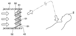
- the guide fin 50 is provided in the internal space of the outlet 40.
- the guide fin 50 is a wind direction variable mechanism that can change the direction of the conditioned air blown from the outlet 40 to an arbitrary vertical direction.
- the fin drive section 60 drives the guide fin 50. Therefore, the fin drive section 60 is a drive section that drives the wind direction variable mechanism.
- the operation of the fin drive unit 60 is controlled by the control device 70.
- the fin drive unit 60 can adjust the direction of the guide fin 50 to an arbitrary position and hold it.
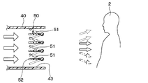
- the guide fin 50 is composed of a plurality of plate members 51.
- Each of the plurality of plate members 51 is vertically arranged with a space therebetween.
- Each of the plurality of plate members 51 is configured such that the angles with respect to the horizontal direction are the same.
- the position of the guide fins 50 is adjusted such that the upstream end 52 of some of the plate members 51 of the plurality of plate members 51 is Can be placed in an upward position that abuts against Some of the plate members 51 are the plate members 51 located at the lowermost side of the plurality of plate members 51.
- the conditioned air is blown toward the upper side in the vehicle cabin more than when the position of the guide fin 50 is the position shown by the broken line in FIG.
- the positioning of the upward position is realized by a part of the plate-like members 51 being in contact with the inner wall 43 of the flow path.
- the positioning of the upward position may be realized by another method.
- the positioning of the upward position may be realized by contacting a part of the plate-shaped members 51 with a structure (not shown) provided in the flow path.
- positioning of the upward position may be realized by a part of the part of the plate-like members 51 different from the end part 53 abutting on the inner wall 43 or the structure of the flow path.
- the guide fins 50 may also be capable of changing the direction of the conditioned air blown from the outlet 40 in the left-right direction.
- the control device 70 is arranged inside the instrument panel 3.
- the control device 70 is composed of a well-known microcomputer including a processor and a memory and its peripheral circuits. Note that the memory of the control device 70 is configured by a non-transitional and substantial storage medium.
- the tilt sensor 20 and the front / rear position sensor 21 are connected to the input side of the control device 70.
- various sensors used for controlling the air conditioner 30 such as an internal air temperature sensor 71 are connected to an input side of the control device 70.
- the inside air temperature sensor 71 detects the temperature of the air inside the vehicle.
- the control device 70 receives vehicle interior environment information such as vehicle interior temperature necessary for controlling the air conditioner 30.
- an operation unit (not shown) of the air conditioner is connected to an input side of the control device 70. When the occupant operates the operation unit, the temperature, air volume, and the like of the conditioned air are set. To the control device 70, setting information such as the temperature and air volume of the conditioned air set by the occupant is input.
- the fin drive unit 60, the blower of the air conditioner 30, the air mix door, and the like are connected to the output side of the control device 70.
- the control device 70 performs various calculations and processes based on a control program stored in the memory. Thereby, the control device 70 controls the operations of the fin drive unit 60 and the blower of the air conditioner 30 based on the detection results of various sensors such as the inclination sensor 20 and the setting information by the operation unit. As a result, the control device 70 controls the direction, temperature, and air volume of the conditioned air blown out from the outlet 40.
- the control device 70 is configured integrally with a control device that controls the air conditioner 30. However, control device 70 may be configured separately from a control device that controls air conditioner 30.
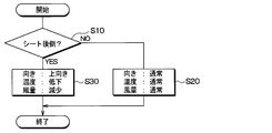
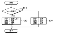
- Control processing executed by the control device 70 of the present embodiment will be described with reference to the flowchart of FIG. 7A.
- This control process is started when the ignition key of the automobile 1 is turned on.
- the automobile 1 is an autonomous vehicle, the operation is started when the traveling switch is turned on. Note that the steps shown in FIG. 7A correspond to functional units that realize various functions.
- step S10 the control device 70 determines whether or not the seat back 12 is in the backward state based on the information transmitted from the inclination sensor 20. Specifically, the control device 70 compares the information on the angle of the seat back 12 transmitted from the inclination sensor 20 with a threshold value stored in advance in the control device 70, and the seat back 12 is in a backward state. It is determined whether or not. When the control device 70 determines that the seat back 12 is not in the backward state (that is, when the determination is NO), the process proceeds to step S20.
- step S20 the control device 70 controls the fin drive unit 60 such that the position of the guide fin 50 is a position arbitrarily set by the occupant.
- the control device 70 does not change the position of the guide fin 50.
- the position of the guide fin 50 is set to a position corresponding to a predetermined portion of the occupant 2.
- the control device 70 changes the position to any position within the range between the broken line position and the dashed line position in FIG. For example, the position of the guide fin 50 in the upright state immediately before the seatback 12 switches from the upright state to the backward state is stored in the memory. The control device 70 changes the position of the guide fin 50 to the position in the upright state.
- the conditioned air blown out from the outlet 40 hits a predetermined portion of the occupant 2.
- the predetermined part of the occupant 2 is the chest.
- the position of the guide fin 50 in FIG. 1 is the position of the solid line in FIG.
- the position of the guide fin 50 can be arbitrarily changed by the operation of the occupant 2.
- control device 70 determines a target temperature and a target air volume of conditioned air blown out from air outlet 40 based on the set temperature, the vehicle interior temperature, and the like.
- the control device 70 controls the operation of the air conditioner 30 so that the temperature and air volume of the conditioned air blown out from the outlet 40 become the determined target temperature and target air volume.
- the control device 70 controls the door position of the air mix door and the air volume of the blower. The temperature and air volume of the conditioned air blown out from the air outlet 40 can be arbitrarily changed by the operation of the occupant 2.
- the direction, temperature, and air volume of the conditioned air blown out from the air outlet 40 are set to an arbitrary direction, an arbitrary temperature, and an arbitrary air volume.
- the conditioned air having an arbitrary temperature and an arbitrary air volume is sent from the air outlet 40 to a predetermined portion of the occupant 2.
- the direction, temperature, and air volume of the conditioned air set when the seat back 12 is in the upright state are referred to as a normal direction, a normal temperature, and a normal air volume.
- the control device 70 determines the blowing mode based on the set temperature, the vehicle interior temperature, and the like.
- the blowing mode include a face mode in which conditioned air is blown out from a face outlet, a defroster mode in which conditioned air is blown out from a defroster outlet, and a foot mode in which conditioned air is blown out from a foot outlet.
- the set temperature is lower than the temperature of the vehicle interior air.
- the blowing mode determined by the control device 70 is the face mode.
- the occupant 2 may select the face mode as the blowing mode.
- step S10 when controller 70 determines that seat back 12 is in the backward state (that is, when YES is determined), control unit 70 proceeds to step S30.
- step S30 the control device 70 controls the fin drive unit 60 such that the position of the guide fin 50 is the upward position shown in FIG.
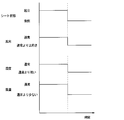
- the direction of the conditioned air blown out from the air outlet 40 is more upward than usual. That is, as shown in FIG. 2, the conditioned air is blown out from the outlet 40.
- the direction of the air-conditioning wind at this time is a direction toward the upper side in the vehicle compartment, as compared with the case where the seat back 12 is in the upright state immediately before switching to the backward state.
- the control device 70 changes the direction of the conditioned air blown out from the outlet 40 to the direction toward the upper side in the vehicle compartment based on the state of the seat back 12 being switched from the standing state to the backward state.
- the fin driving unit 60 is controlled.
- the temperature of the conditioned air is lower than the temperature of the vehicle interior air
- the density of the conditioned air is higher than that of the vehicle interior air.
- the conditioned air blown out toward the upper side of the passenger compartment falls toward the occupant while falling by gravity.
- the direction of the conditioned air flowing toward the occupant while falling is closer to the vertical direction than before the change in the direction of the conditioned air blown out from the outlet 40.
- control device 70 lowers the target temperature of the conditioned air blown out from blowout port 40.
- the control device 70 controls the air conditioner 30 so that the temperature of the conditioned air blown out from the outlet 40 becomes the lowered target temperature.
- the temperature of the conditioned air blown out from the air outlet 40 becomes lower than normal. More specifically, the temperature of the conditioned air blown out from the air outlet 40 is lower than when the seat back 12 is in the standing state immediately before switching to the backward state.
- the control device 70 lowers the temperature of the conditioned air blown out from the outlet 40 based on the switching of the state of the seat back 12 from the standing state to the backward state.
- the density of the conditioned air increases as compared to before the temperature of the conditioned air decreases. For this reason, the difference in density between the conditioned air and the vehicle interior air becomes larger, so that the direction of the conditioned air toward the occupant while falling is closer to the vertical direction.
- control device 70 controls air conditioner 30 so as to reduce the amount of conditioned air blown out from outlet 40.
- control of the air conditioner 30 is to reduce the air volume of the blower.
- the air volume of the conditioned air blown out from the air outlet 40 is smaller than usual. Specifically, the amount of conditioned air blown out from the outlet 40 is reduced as compared with the standing state immediately before the seat back 12 is switched to the backward state. As described above, the control device 70 reduces the amount of the conditioned air blown out from the outlet 40 based on the switching of the state of the seat back 12 from the standing state to the backward state.
- the control device 70 reduces the amount of the conditioned air blown out from the outlet 40.
- the amount of decrease in the air volume at this time is set in advance by an experiment or the like so that even when the seat back 12 is switched to the backward state, the conditioned air is applied to a predetermined portion of the same occupant as in the upright state. 70 is stored in the memory. In other words, the control device 70 reduces the amount of conditioned air blown out from the air outlet so that the conditioned air is applied to the same predetermined part of the occupant as when standing.
- the conditioned air can be applied to the same part of the occupant as when the seat back 12 is in the upright state.
- the control device 70 also determines whether the position of the seat cushion 11 in the vehicle longitudinal direction has been changed based on information transmitted from the longitudinal position sensor 21.
- control device 70 adjusts the amount of conditioned air blown out from the outlet according to the position of seat cushion 11.
- the adjustment amount of the air volume at this time is set in advance by an experiment or the like so that the conditioned air is applied to a predetermined portion of the occupant in the same state as in the standing state, and is stored in the memory of the control device 70.
- the conditioned air is applied to the same part of the occupant as when the seat back 12 was standing up. be able to.
- Comparative Example 2 corresponds to the case where the above-described combination device blows wind from the face outlet toward the occupant's chest when the seatback is in the backward state.
- the position of the guide fins 50 when the seat back 12 is in the backward position is the position where the wind is blown straight out from the outlet 40 toward the occupant's 2 chest.
- the linear shape means a state close to a straight line.
- the outlet is located at a lower position than in the device of Patent Document 1 described above. Furthermore, in Comparative Example 2, the direction of the conditioned air blown out from the air outlet 40 when the seat back 12 is in the backward state is a direction toward the lower side than when the seat back 12 is in the upright state. For this reason, when the seat back 12 is in the backward position, as shown in FIG. 8, the conditioned air blown out from the outlet 40 reaches the chest of the occupant 2 and then moves downward along the body of the occupant 2. Flows upward from. This may cause the occupant 2 to feel uncomfortable as described above.
- the conditioned air blown out from the air outlet 40 toward the occupant 2 is blown out from the air outlet 40 toward the upper side of the passenger compartment, so that The wind is like falling from above. Thereby, it is possible to suppress the occupant 2 from feeling uncomfortable.
- the conditioned air is blown to the chest of the occupant 2.
- the conditioned air may be applied to a predetermined portion other than the chest of the occupant 2. Examples of the predetermined portion other than the chest include a neck, an abdomen, and a thigh.
- the control device 70 controls the guide fins 50 and the air conditioning The device 30 is controlled.
- the control device 70 may control the guide fins 50 and the air conditioner 30 so as to blow the conditioned air to a part of the occupant different from that in the standing state.
- the reduction amount of the air flow when the control device 70 reduces the air flow of the conditioned air may be set so that the conditioned air is applied to the occupant 2 when the seat back 12 is switched to the backward state. . Thereby, even if the seat back 12 is in the backward state, the conditioned air of the occupant 2 can be blown to the predetermined portion.
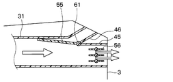
- the automotive air-conditioning control system includes a face outlet 45, a dedicated outlet 46, a switching door 55, and a door driving unit 61.
- the face outlet 45 corresponds to the outlet 40 of the first embodiment.
- Guide fins 56 are arranged in the internal space of the face outlet 45.
- the guide fins 56 change the direction of the conditioned air blown from the outlet 40 in the vertical direction, similarly to the guide fins 50 of the first embodiment.
- the range in which the guide fins 56 change the direction of the conditioned air does not include the direction of the conditioned air shown in FIG.
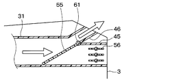
- the dedicated outlet 46 is provided above the face outlet 45 in the instrument panel 3.
- the dedicated outlet 46 is connected to the duct 31 that connects the air conditioner 30 and the face outlet 45.
- the dedicated air outlet 46 blows out the conditioned air toward the upper side of the vehicle interior than the face air outlet 45.
- the switching door 55 is disposed on the upstream side of the face outlet 45 and the dedicated outlet 46 in the duct 31.
- the switching door 55 switches between the airflow of the conditioned air generated by the air conditioner 30 toward the face outlet 45 and the airflow of the conditioned air generated by the air conditioner 30 toward the dedicated air outlet 46.
- the door driving unit 61 drives the switching door 55.
- the operation of the door drive unit 61 is controlled by the control device 70.
- the face air outlet 45 and the dedicated air outlet 46 are provided in the instrument panel 3 and correspond to air outlets for blowing the conditioned air generated by the air conditioner into the vehicle interior.
- the switching door 55 corresponds to a wind direction variable mechanism that can change the direction of the conditioned air blown out from the outlet in the up-down direction.
- the door drive unit 61 corresponds to a drive unit that drives the wind direction variable mechanism.
- control processing executed by the control device 70 of the first embodiment is changed as follows.
- step S20 the control device 70 sets the position of the switching door 55 to the position where the conditioned air generated by the air conditioner 30 goes to the face outlet 45 as shown in FIG.
- the conditioned air is blown from the face outlet 45 toward the upper body of the occupant 2.
- step S30 the control device 70 controls the door driving unit 61 so that the position of the switching door 55 is set to the position where the conditioned air generated by the air conditioner 30 is directed to the dedicated outlet 46 as shown in FIG. Control.
- the control device 70 controls the fin drive unit 60 so that the direction of the conditioned air blown out from the outlet changes to the direction toward the upper side in the vehicle interior.
- control process The other parts of the control process are the same as those of the first embodiment. Therefore, also in the present embodiment, the same effect as in the first embodiment can be obtained. Further, according to the present embodiment, the following effects can be obtained.
- the pressure loss of the conditioned air by the guide fins 56 of the face outlet 45 is eliminated by blowing the conditioned air from the dedicated outlet 46. Therefore, the conditioned air blown out from the dedicated air outlet 46 can be efficiently delivered to the occupant 2.
- step S30 in FIG. 7A is changed to step S40.
- step S40 the control device 70 does not change the direction of the conditioned air blown out from the outlet 40 from the normal direction.
- the control device 70 lowers the target temperature of the conditioned air blown out from the outlet 40.
- the control device 70 controls the air conditioner 30 so that the temperature of the conditioned air blown out from the outlet 40 becomes the lowered target temperature.
- the temperature of the conditioned air blown out from the outlet 40 is lower than usual. More specifically, the temperature of the conditioned air blown out from the air outlet 40 is lower than when the seat back 12 is in the standing state immediately before switching to the backward state. As described above, the control device 70 lowers the temperature of the conditioned air blown out from the outlet 40 based on the switching of the state of the seat back 12 from the standing state to the backward state.
- the temperature of the conditioned air generated by the air conditioner 30 is lower than the temperature of the vehicle interior air. Therefore, the conditioned air has a higher density than the vehicle interior air. Further, the temperature of the conditioned air blown from the outlet 40 is reduced by step S40. Thereby, the density of the conditioned air is further increased. Therefore, as shown in FIG. 12, the conditioned air blown out from the outlet 40 is directed toward the occupant while falling by gravity. The direction of the conditioned air heading toward the occupant while falling is closer to the vertical direction than before the temperature of the conditioned air is lowered. Therefore, according to the present embodiment, the same effect as that of the first embodiment can be obtained.
- control device 70 controls air conditioner 30 so as to increase the amount of conditioned air blown out from outlet 40.
- the control of the air conditioner 30 is, specifically, to increase the air volume of the blower.
- the control device 70 increases the amount of the conditioned air blown out from the outlet 40 based on the switching of the state of the seat back 12 from the standing state to the backward state.
- control device 70 increases the amount of the conditioned air blown out of the outlet 40.
- the amount of increase in the air volume at this time is set in advance by an experiment or the like so that even when the seat back 12 is switched to the backward state, the conditioned air is applied to a predetermined portion of the same occupant as in the upright state. 70 is stored in the memory. In other words, control device 70 increases the flow rate of the conditioned air blown out from the outlet so that the conditioned air blows on the same part of occupant 2 as when seatback 12 is in the upright state.
- the conditioned air can be applied to the same portion as when the seat back 12 is in the upright state.
- the control device 70 may increase the amount of the conditioned air so as to blow the conditioned air to a part of the occupant different from that in the upright state. .
- the amount of increase in the airflow is set so that the conditioned air is blown against the occupant 2 when the seat back 12 is switched to the backward state. Thereby, even if the seat back 12 is in the backward state, the conditioned air of the occupant 2 can be blown to the predetermined portion.
- step S30 of the control processing according to the first embodiment the control device 70 controls the fin drive unit 60 so that the position of the guide fin 50 is the upward position shown in FIG.
- the position of the guide fins 50 at this time may not be the upward position shown in FIG. 6 as long as the direction of the conditioned air blown out from the outlet 40 changes to the upward direction in the vehicle interior.
- the control device 70 may change the position of the guide fin 50 to the broken line position in FIG. Further, when the position of the guide fin 50 in the upright state is the position indicated by the one-dot chain line in FIG. 5, the control device 70 may change the position of the guide fin 50 to the solid line position in FIG. As described above, the control device 70 changes the direction of the conditioned air blown out from the outlet 40 to the direction toward the upper side in the vehicle compartment based on the state of the seat back 12 being switched from the standing state to the backward state. Thus, the fin drive unit 60 may be controlled.
- the direction of the conditioned air blown out from the air outlet 40 is the same as the direction toward the upper side of the vehicle compartment as compared with the standing state immediately before switching to the backward state. Become. Then, since the temperature of the conditioned air is lower than the temperature of the cabin air, the conditioned air blown out toward the upper side of the cabin goes toward the occupant while falling by gravity. The direction of the conditioned air flowing toward the occupant while falling is closer to the vertical direction than before the change in the direction of the conditioned air blown out from the outlet 40. Therefore, the same effect as in the first embodiment can be obtained.
- the inclination sensor 20 is used as the seat back state detection unit.
- a rotation angle sensor that detects the rotation angle of a motor that moves the seat back 12
- an in-vehicle camera that images the seat 10 or the occupant 2 on the seat 10 may be used as the seat back state detection unit.
- the control device 70 compares the information transmitted from the rotation angle sensor with a threshold value stored in advance in the control device 70 in step S10 of the control processing of the first embodiment, It is determined whether or not the seat back 12 is in the backward state.
- control device 70 analyzes the image captured by the in-vehicle camera in step S10 of the control processing of the first embodiment, and determines whether or not the seat back 12 is in a backward state. Is determined.
- the sleep switch may be used as the seat back state detecting unit. In this case, is transmitted to the control device 70.
- the control device 70 determines whether or not the seat back 12 is in the backward state based on the information on whether or not the sleep switch transmitted from the sleep switch is turned on.
- the control device 70 sets the target temperature of the conditioned air blown from the outlet 40 in order to reduce the temperature of the conditioned air blown from the outlet 40. Had been lowered. However, the control device 70 may operate the cooling device provided in the duct 31 instead of lowering the target temperature of the conditioned air.
- step S30 the control device 70 reduces the air volume of the blower in order to reduce the air volume of the conditioned air blown out from the air outlet 40.
- the control device 70 may lower the air distribution ratio of the air outlet 40 by moving the air outlet mode door that switches the air outlet mode of the air conditioner 30 instead of reducing the air volume of the blower.
- the control device 70 may narrow the opening of the outlet 40 by the opening adjusting mechanism.
- step S40 the control device 70 increases the air volume of the blower in order to increase the air volume of the conditioned air blown out from the air outlet 40.
- the control device 70 may increase the air distribution ratio of the air outlet 40 by moving the air outlet mode door that switches the air outlet mode of the air conditioner 30 instead of increasing the air volume of the blower.
- the controller 70 may widen the opening of the outlet 40 by the opening adjusting mechanism.
- the present disclosure is applied to a general face outlet.
- the present disclosure can be applied to an outlet different from a general face outlet as long as the outlet is an outlet provided in the instrument panel and blows conditioned air toward an occupant. is there.
- an air conditioning control system for a vehicle includes a seat disposed in a vehicle interior and an air conditioning system that generates conditioned air that is lower in temperature than the vehicle interior air.
- Device an air outlet provided on the instrument panel, for blowing air-conditioned air into the vehicle interior, a variable air direction mechanism capable of changing the direction of the air-conditioned air blown from the air outlet in the vertical direction, and a drive unit for driving the variable air direction mechanism
- a detection unit that detects a state of a seat back of the seat; and a control device that controls the driving unit based on a detection result of the detection unit.
- the control device controls the drive unit so that the direction of the conditioned air blown out from the outlet changes to the direction toward the upper side of the vehicle compartment based on the switching of the seat back state from the standing state to the backward state.
- control device changes the temperature of the conditioned air blown out from the outlet based on the fact that the state of the seat back has been switched from the standing state to the backward state. Lower.
- the temperature of the conditioned air blown out from the outlet decreases.
- the density of the conditioned air increases as compared to before the temperature of the conditioned air decreases. For this reason, the difference in density between the conditioned air and the vehicle interior air becomes larger, so that the direction of the conditioned air toward the occupant while falling is closer to the vertical direction.
- the wind blown out from the air outlet can be further suppressed from flowing upward along the occupant's body after reaching the occupant's predetermined portion. it can.
- control device may control the air-conditioning air blown out from the air outlet based on the fact that the state of the seat back is switched from the upright state to the backward state. To reduce the air volume.
- the control device is blown out from the outlet. Reduce the volume of air-conditioning air. Thereby, even if the seat back is in a backward state, air conditioning air can be blown to a predetermined part of the occupant.
- control device reduces the amount of conditioned air blown out from the air outlet so that the conditioned air blows to the same predetermined portion of the occupant as when standing. Thereby, even if the seat back is in the backward state, the conditioned air can be applied to the same predetermined portion of the occupant as when the seat back is in the upright state.
- an automotive air conditioning control system in an instrument panel, a seat disposed in a vehicle interior, an air conditioner that generates conditioned air that is lower in temperature than the vehicle interior air, An outlet for blowing the wind into the vehicle interior, a detecting unit for detecting a state of a seat back of the seat, and a control device for controlling the temperature of the conditioned air blown from the outlet based on a detection result of the detecting unit.
- the control device lowers the temperature of the conditioned air blown out from the air outlet based on the switching of the seat back state from the upright state to the backward state.
- control device changes the amount of air-conditioned air blown out from the outlet based on the fact that the state of the seat back has been switched from the standing state to the backward state. Increase.
- the control device increases the amount of conditioned air blown out from the outlet. Thereby, even if the seat back is in a backward state, air conditioning air can be blown to a predetermined part of the occupant.
- control device increases the amount of the conditioned air blown out from the air outlet so that the conditioned air is blown against the occupant at the same position as when the seat back is in the upright state. Thereby, even if the seat back is in the backward state, the air conditioning air can be applied to the same portion as when the seat back is in the upright state.
- the control device is used for air conditioning of an automobile.
- This vehicle has a seat disposed in a vehicle interior, an air conditioner that generates conditioned air that is lower in temperature than the vehicle interior air, an air outlet provided on an instrument panel, and an air outlet that blows the air conditioned air into the vehicle interior, and an air outlet.
- the air conditioner includes a wind direction variable mechanism that can change the direction of the conditioned air to be blown up and down, a drive unit that drives the wind direction variable mechanism, and a detection unit that detects the state of the seat back of the seat.
- the control device controls the drive unit so that the direction of the conditioned air blown out from the outlet changes to the direction toward the upper side of the vehicle compartment based on the switching of the seat back state from the standing state to the backward state. I do.
- the control device is used for air conditioning of an automobile.
- This vehicle has a seat disposed in a vehicle interior, an air conditioner that generates conditioned air that is lower in temperature than the vehicle interior air, an air outlet that is provided in an instrument panel and blows out the conditioned air into the vehicle interior, and a seat.
- a detection unit that detects a state of the seat back. The control device lowers the temperature of the conditioned air blown out from the air outlet based on the switching of the seat back state from the upright state to the backward state.
Abstract
This automobile air-conditioning control system comprises: a seat (10) which is disposed in the passenger compartment; an air conditioner (30) which generates air-conditioned air that is lower in temperature than the passenger compartment air; a blowout port (40) which is provided in an instrument panel (3) and blows the air-conditioned air into the passenger compartment; a wind direction variable mechanism (50) that can change the vertical direction of the air-conditioned air blown out from the blowout port; a drive unit (60) which drives the wind direction variable mechanism; a detection unit (20) which detects the state of the seat back (12) of the seat; and a control device (70) which controls the drive unit on the basis of the detection result of the detection unit. The control device controls the drive unit so that the direction of the air-conditioned air blown out from the blowout port changes to a direction facing the upper side of the passenger compartment in response to the switching of the seat back state from an upright position to a reclining position.
Description
本出願は、2018年10月4日に出願された日本特許出願番号2018-189328号に基づくもので、ここにその記載内容が参照により組み入れられる。
This application is based on Japanese Patent Application No. 2018-189328 filed on October 4, 2018, the disclosure of which is incorporated herein by reference.
本開示は、自動車用空調制御システムおよび制御装置に関するものである。
The present disclosure relates to a vehicle air conditioning control system and a control device.
特許文献1には、自動車のルームミラーに設けられた送風装置の吹出口の向きを、位置センサが検出したシートバックの角度に応じて可変することで、シートバックの角度によらず乗員の所定部位へ風を吹き出すものが記載されている。
Patent Literature 1 discloses that a direction of an air outlet of an air blower provided in a rearview mirror of an automobile is changed according to an angle of a seatback detected by a position sensor, so that a predetermined occupant of the occupant is independent of the angle of the seatback. What blows wind to a part is described.
ところで、一般的な自動車用空調装置においては、インストルメントパネル(以下「インパネ」という)に設けられたフェイス吹出口から乗員の上半身に向けて風を吹き出す。このような自動車用空調装置に対し特許文献1に記載の送風装置の考え方を適用したもの(以下、「組合せ装置」という)を考えた場合、フェイス吹出口から吹き出される風の向きを、シートバックの角度に応じて可変することになる。
By the way, in a general automotive air conditioner, a wind is blown out from a face outlet provided in an instrument panel (hereinafter referred to as an instrument panel) toward the upper body of the occupant. In a case where the concept of the blower described in Patent Document 1 is applied to such an automotive air conditioner (hereinafter, referred to as a “combination device”), the direction of the wind blown out from the face outlet is determined by a sheet. It will vary according to the angle of the back.
ここで、シートバックの角度によらず乗員の胸部へ風を吹き出すことを考えた場合、特許文献1の装置は、吹出口の位置が天井付近で高いため、シートバックが後方へ倒れた状態(以下「後倒状態」という)であっても、風を乗員胸部へ当てやすい。しかしながら、特許文献1の装置は、インパネの内側に配置されている空調装置から天井にダクトを持っていかなければならない、または、空調装置が有する送風機とは別に送風機を設置しなければならないという問題がある。
Here, when considering blowing the wind to the occupant's chest regardless of the angle of the seat back, the device of Patent Document 1 has a state in which the seat back falls down rearward because the position of the air outlet is high near the ceiling ( (Hereinafter referred to as "rearward state"), it is easy to blow the wind to the occupant's chest. However, the device of Patent Literature 1 has a problem that a duct must be taken from an air conditioner arranged inside the instrument panel to a ceiling, or a blower must be installed separately from a blower included in the air conditioner. There is.
組合せ装置の場合、インパネにフェイス吹出口が設けられているので上記問題はない。しかし、組合せ装置の場合、吹出口が、特許文献1の装置に比べて低い位置にある。さらに、組合せ装置では、シートバックが後倒状態のときに、フェイス吹出口から吹き出される風の向きを、フェイス吹出口から乗員の胸部に向けて直線状に風が吹き出される向きとする。このため、フェイス吹出口から吹き出された風は、乗員の胸部に到達した後、乗員の体に沿って下側から上側に向かって流れる。
In the case of a combination device, the above problem does not occur since the face outlet is provided in the instrument panel. However, in the case of the combination device, the outlet is located at a lower position than the device of Patent Document 1. Furthermore, in the combination device, when the seat back is in the backward state, the direction of the wind blown out from the face outlet is the direction in which the wind is blown straight out from the face outlet toward the occupant's chest. For this reason, the wind blown out from the face outlet reaches the chest of the occupant and then flows from the lower side to the upper side along the occupant's body.
乗員の胸部に到達した風が、乗員の体に沿って上側に向かって流れると、乗員が不快に感じる場合がある。例えば、乗員に到達した風が乗員の体に沿って上側に向かって風が流れることに対して、乗員が慣れていない場合、乗員は、その風の流れに対して不快に感じる。また、乗員が顔部に風が到達することを避けたい場合、乗員は、乗員の胸部に到達した風が顔部へ到達することに対して不快に感じる。また、乗員に到達した風が乗員の体に沿って流れることで、風の温度が乗員の体温によって変化する。このため、乗員の顔部に到達する風の温度が、吹出口から吹き出される風の温度と異なることで、乗員が不快に感じる。
風 When the wind that reaches the occupant's chest flows upward along the occupant's body, the occupant may feel uncomfortable. For example, if the occupant is not accustomed to the wind that has reached the occupant flowing upward along the occupant's body, the occupant feels uncomfortable with the flow of the wind. Further, when the occupant wants to avoid the wind from reaching the face, the occupant feels uncomfortable with the wind reaching the chest of the occupant reaching the face. Further, the wind that has reached the occupant flows along the occupant's body, so that the temperature of the wind changes according to the occupant's body temperature. Therefore, the occupant feels uncomfortable when the temperature of the wind reaching the occupant's face is different from the temperature of the wind blown out from the outlet.
このように、組合せ装置では、シートバックが後倒状態のときに、フェイス吹出口から吹き出される風が、乗員の胸部に到達した後、乗員の体に沿って上側に向かって流れる。このため、乗員が不快に感じてしまうという、特許文献1にはない新しい課題があることを本発明者らは見出した。なお、この新しい課題は、フェイス吹出口以外のインパネに設けられた吹出口から風を吹き出す場合においても、同様に生じる。また、この新しい課題は、乗員の胸部以外の所定部位に向けて吹出口から風を吹き出す場合においても、同様に生じる。
As described above, in the combination device, when the seat back is in the backward state, the wind blown out from the face air outlet reaches the chest of the occupant and then flows upward along the occupant's body. For this reason, the present inventors have found that there is a new problem that the occupant feels uncomfortable, which is not found in Patent Document 1. Note that this new problem also occurs when air is blown out from an outlet provided on an instrument panel other than the face outlet. This new problem also occurs when the air is blown out from the air outlet toward a predetermined portion other than the occupant's chest.
本開示は、シートバックが後倒状態のときに、吹出口から吹き出された風が、乗員の所定部位に到達した後、乗員の体に沿って上側に向かって流れることを抑制できる自動車用空調制御システムおよび制御装置を提供することを目的とする。
The present disclosure is directed to an automotive air conditioner that can suppress the wind blown from an air outlet from flowing upward along an occupant's body after reaching a predetermined portion of the occupant when the seat back is in a backward state. It is an object to provide a control system and a control device.
上記目的を達成するため、本開示の1つの観点によれば、
自動車用空調制御システムは、
車室内に配置されたシートと、
車室内空気よりも低温の空調風を生成する空調装置と、
インストルメントパネルに設けられ、空調風を車室内に吹き出す吹出口と、
吹出口から吹き出される空調風の向きを上下方向で変更できる風向可変機構と、
風向可変機構を駆動する駆動部と、
シートが有するシートバックの状態を検出する検出部と、
検出部の検出結果に基づいて、駆動部を制御する制御装置とを備え、
制御装置は、シートバックの状態が起立状態から後倒状態に切り替わったことに基づいて、吹出口から吹き出される空調風の向きが車室内の上側に向かう向きに変わるように、駆動部を制御する。 To achieve the above object, according to one aspect of the present disclosure,
Automotive air conditioning control systems
A seat placed in the passenger compartment,
An air conditioner that generates conditioned air that is lower in temperature than the cabin air;
An outlet provided on the instrument panel for blowing air-conditioned air into the vehicle interior;
A wind direction variable mechanism that can change the direction of the conditioned air blown out from the outlet in a vertical direction,
A drive unit for driving the wind direction variable mechanism,
A detection unit that detects a state of a seat back of the seat,
A control device that controls the drive unit based on the detection result of the detection unit,
The control device controls the drive unit so that the direction of the conditioned air blown out from the outlet changes to the direction toward the upper side of the vehicle compartment based on the switching of the seat back state from the standing state to the backward state. I do.
これによれば、シートバックの状態が起立状態から後倒状態に切り替わると、吹出口から吹き出される空調風の向きが車室内の上側に向かう向きに変わる。このとき、吹出口から吹き出される空調風の温度は車室内空気の温度よりも低いので、空調風の方が車室内空気よりも密度が大きい。このため、車室内の上側に向かって吹き出された空調風は、重力によって落下しながら乗員に向かう。この落下しながら乗員に向かう空調風の向きは、吹出口から吹き出される空調風の向きの変更前と比較して、鉛直方向に近い向きとなる。
According to this, when the state of the seat back is switched from the standing state to the backward state, the direction of the conditioned air blown out from the outlet changes to the direction toward the upper side in the vehicle interior. At this time, since the temperature of the conditioned air blown out from the outlet is lower than the temperature of the vehicle interior air, the conditioned air has a higher density than the vehicle interior air. For this reason, the conditioned air blown out toward the upper side of the passenger compartment falls toward the occupant while falling by gravity. The direction of the conditioned air flowing toward the occupant while falling is closer to the vertical direction than before the change in the direction of the conditioned air blown out from the outlet.
このように、吹出口から乗員に向けて吹き出された空調風は、吹出口から車室内の上側に向かって吹き出されることで、乗員に対して上方から降り注ぐような風となる。これにより、シートバックが後倒状態のときに、吹出口から吹き出された風が、乗員の所定部位に到達した後、乗員の体に沿って上側に向かって流れることを抑制することができる。
空調 In this way, the conditioned air blown out from the air outlet toward the occupant is blown out from the air outlet toward the upper side of the vehicle interior, so that the conditioned air flows downward from above toward the occupant. Thereby, when the seat back is in the backward state, the wind blown out from the outlet can be suppressed from flowing upward along the occupant's body after reaching the occupant's predetermined portion.
別の観点によれば、
自動車用空調制御システムは、
車室内に配置されたシートと、
車室内空気よりも低温の空調風を生成する空調装置と、
インストルメントパネルに設けられ、空調風を車室内に吹き出す吹出口と、
シートが有するシートバックの状態を検出する検出部と、
検出部の検出結果に基づいて、駆動部を制御する制御装置とを備え、
制御装置は、シートバックの状態が起立状態から後倒状態に切り替わったことに基づいて、吹出口から吹き出される空調風の温度を低下させる。 According to another perspective,
Automotive air conditioning control systems
A seat placed in the passenger compartment,
An air conditioner that generates conditioned air that is lower in temperature than the cabin air;
An outlet provided on the instrument panel for blowing air-conditioned air into the vehicle interior;
A detection unit that detects a state of a seat back of the seat,
A control device that controls the drive unit based on the detection result of the detection unit,
The control device lowers the temperature of the conditioned air blown out from the air outlet based on the switching of the seat back state from the upright state to the backward state.
これによれば、空調装置で生成される空調風の温度は車室内空気の温度よりも低いので、空調風の方が車室内空気よりも密度が大きい。さらに、シートバックの状態が起立状態から後倒状態に切り替わると、吹出口から吹き出される空調風の温度が低下する。これにより、空調風の密度がより大きくなる。このため、吹出口から吹き出された空調風は、重力によって落下しながら乗員に向かう。この落下しながら乗員に向かう空調風の向きは、空調風の温度を低下させる前と比較して、鉛直方向に近い向きとなる。この結果、シートバックが後倒状態のときに、吹出口から吹き出された風が、乗員の所定部位に到達した後、乗員の体に沿って上側に向かって流れることを抑制することができる。
According to this, since the temperature of the conditioned air generated by the air conditioner is lower than the temperature of the vehicle interior air, the conditioned air has a higher density than the vehicle interior air. Further, when the state of the seat back is switched from the standing state to the backward state, the temperature of the conditioned air blown out from the outlet decreases. Thereby, the density of the conditioned air is further increased. For this reason, the conditioned air blown out from the outlet exits toward the occupant while falling by gravity. The direction of the conditioned air heading toward the occupant while falling is closer to the vertical direction than before the temperature of the conditioned air is lowered. As a result, when the seat back is in the backward state, the wind blown out from the outlet can be suppressed from flowing upward along the occupant's body after reaching the occupant's predetermined portion.
さらに別の観点によれば、制御装置は、自動車の空調に用いられる。この自動車は、車室内に配置されたシートと、車室内空気よりも低温の空調風を生成する空調装置と、インストルメントパネルに設けられ、空調風を車室内に吹き出す吹出口と、吹出口から吹き出される空調風の向きを上下方向で変更できる風向可変機構と、風向可変機構を駆動する駆動部と、シートが有するシートバックの状態を検出する検出部と、を備える。
According to yet another aspect, the control device is used for air conditioning of an automobile. This vehicle has a seat disposed in a vehicle interior, an air conditioner that generates conditioned air that is lower in temperature than the vehicle interior air, an air outlet provided on an instrument panel, and an air outlet that blows the air conditioned air into the vehicle interior, and an air outlet. The air conditioner includes a wind direction variable mechanism that can change the direction of the conditioned air to be blown up and down, a drive unit that drives the wind direction variable mechanism, and a detection unit that detects the state of the seat back of the seat.
そして、制御装置は、シートバックの状態が起立状態から後倒状態に切り替わったことに基づいて、吹出口から吹き出される空調風の向きが車室内の上側に向かう向きに変わるように、駆動部を制御する。これによれば、上記した1つの観点の自動車用空調制御システムと同様の効果が得られる。
Then, the control device is configured to change the direction of the conditioned air blown from the air outlet to the direction toward the upper side of the vehicle interior based on the switching of the seat back state from the standing state to the backward state. Control. According to this, the same effect as the above-described vehicle air conditioning control system of one aspect can be obtained.
さらに別の観点によれば、制御装置は、自動車の空調に用いられる。この自動車は、車室内に配置されたシートと、車室内空気よりも低温の空調風を生成する空調装置と、インストルメントパネルに設けられ、空調風を車室内に吹き出す吹出口と、シートが有するシートバックの状態を検出する検出部と、を備える。
According to yet another aspect, the control device is used for air conditioning of an automobile. This vehicle has a seat disposed in a vehicle interior, an air conditioner that generates conditioned air that is lower in temperature than the vehicle interior air, an air outlet that is provided in an instrument panel and blows out the conditioned air into the vehicle interior, and a seat. A detection unit that detects a state of the seat back.
そして、制御装置は、シートバックの状態が起立状態から後倒状態に切り替わったことに基づいて、吹出口から吹き出される空調風の温度を低下させる。これによれば、上記した別の観点の自動車用空調制御システムと同様の効果が得られる。
{Circle around (5)} The control device lowers the temperature of the conditioned air blown out from the outlet based on the fact that the state of the seat back is switched from the upright state to the backward state. According to this, the same effect as the above-described vehicle air conditioning control system of another aspect can be obtained.
なお、各構成要素等に付された括弧付きの参照符号は、その構成要素等と後述する実施形態に記載の具体的な構成要素等との対応関係の一例を示すものである。
Note that the reference numerals in parentheses attached to the respective components and the like indicate an example of the correspondence between the components and the like and the specific components and the like described in the embodiments described later.
以下、本開示の実施形態について図に基づいて説明する。なお、以下の各実施形態相互において、互いに同一もしくは均等である部分には、同一符号を付して説明を行う。
Hereinafter, embodiments of the present disclosure will be described with reference to the drawings. In the following embodiments, parts that are the same or equivalent are denoted by the same reference numerals and described.
(第1実施形態)
図1、2に示す本実施形態の自動車用空調制御システムは、乗員が乗車する自動車1に用いられ、車室内の空調を制御する。具体的には、この自動車用空調制御システムは、吹出口から吹き出される空調風の向きを制御する。自動車用空調制御システムが用いられる自動車1は、乗員2が運転操作を行う自動車に加え、加速、操舵、制動、および周囲の監視などの全ての運転操作を自動運転システムが行う自動運転車を含んでいる。なお、自動運転車の場合、車両走行中にシートバックを後方へ倒した状態(以下「後倒状態」という)で乗員が乗車することも可能である。 (1st Embodiment)
The automotive air-conditioning control system of the present embodiment shown in FIGS. Specifically, this automotive air conditioning control system controls the direction of the conditioned air blown from the outlet. Thevehicle 1 in which the vehicle air-conditioning control system is used includes, in addition to the vehicle in which the occupant 2 performs the driving operation, an automatic driving vehicle in which the automatic driving system performs all the driving operations such as acceleration, steering, braking, and surrounding monitoring. In. In the case of an autonomous vehicle, an occupant can ride in a state in which the seat back is tilted backward while the vehicle is running (hereinafter, referred to as a "rearward state").
図1、2に示す本実施形態の自動車用空調制御システムは、乗員が乗車する自動車1に用いられ、車室内の空調を制御する。具体的には、この自動車用空調制御システムは、吹出口から吹き出される空調風の向きを制御する。自動車用空調制御システムが用いられる自動車1は、乗員2が運転操作を行う自動車に加え、加速、操舵、制動、および周囲の監視などの全ての運転操作を自動運転システムが行う自動運転車を含んでいる。なお、自動運転車の場合、車両走行中にシートバックを後方へ倒した状態(以下「後倒状態」という)で乗員が乗車することも可能である。 (1st Embodiment)
The automotive air-conditioning control system of the present embodiment shown in FIGS. Specifically, this automotive air conditioning control system controls the direction of the conditioned air blown from the outlet. The
図1、2に示すように、自動車用空調制御システムは、シート10、傾斜センサ20、前後位置センサ21、空調装置30、吹出口40、ガイドフィン50、フィン駆動部60および制御装置70等を備えている。
As shown in FIGS. 1 and 2, the automotive air conditioning control system includes a seat 10, an inclination sensor 20, a front / rear position sensor 21, an air conditioner 30, an air outlet 40, a guide fin 50, a fin drive unit 60, a control device 70, and the like. Have.
シート10は、車室内に配置されている。シート10は、乗員に着座される。シート10は、乗員2の臀部等を支持するシートクッション11と、乗員2の背中を支持するシートバック12とを有している。シートバック12は、シートクッション11に対する角度を変更可能に設けられている。また、シート10は、車室床面に対し車両前後方向に移動可能に設けられている。
The seat 10 is arranged in the vehicle interior. The seat 10 is seated on an occupant. The seat 10 has a seat cushion 11 that supports the buttocks of the occupant 2 and a seat back 12 that supports the back of the occupant 2. The seat back 12 is provided so that the angle with respect to the seat cushion 11 can be changed. Further, the seat 10 is provided so as to be movable in the vehicle front-rear direction with respect to the vehicle cabin floor.
傾斜センサ20は、シート10に設けられている。傾斜センサ20は、シートバック12の状態を検出するシートバック状態検出部である。傾斜センサ20は、シートクッション11に対するシートバック12の角度を検出する。傾斜センサ20は、検出した情報を制御装置70に伝送する。制御装置70は、傾斜センサ20から伝送される情報に基づいて、シートバック12が起立状態と後倒状態とのどちらの状態であるかを判定する。後倒状態とは、シートバック12が起立状態よりも車両の後方へ倒れた状態である。
The tilt sensor 20 is provided on the seat 10. The tilt sensor 20 is a seat back state detection unit that detects the state of the seat back 12. The tilt sensor 20 detects an angle of the seat back 12 with respect to the seat cushion 11. The tilt sensor 20 transmits the detected information to the control device 70. Control device 70 determines whether seatback 12 is in the upright state or the backward state based on information transmitted from tilt sensor 20. The backward state is a state in which the seat back 12 has fallen rearward of the vehicle from the standing state.
前後位置センサ21は、シート10に設けられている。前後位置センサ21は、シートクッション11の車両前後方向の位置を検出する。前後位置センサ21は、検出した情報を制御装置70に伝送する。
The front / rear position sensor 21 is provided on the seat 10. The front / rear position sensor 21 detects the position of the seat cushion 11 in the vehicle front / rear direction. The front / rear position sensor 21 transmits the detected information to the control device 70.
空調装置30は、インパネ3の内側に配置されている。インパネ3は、計器類が配置されている部分だけでなく、オーディオやエアコンを収納する部分を含む、車室内の前席正面に配置されたパネル全体である。空調装置30は、温度および湿度が調整された空調風を生成する。具体的には、空調装置30は、車室内空気よりも低温の空調風を生成する。空調装置30は、空調ケースを有する。空調ケースの内部に送風機、冷却器、加熱器、エアミックスドアなどが配置される。送風機は、車室内に向かう空気流れを形成する。冷却器は、車室内に向かう空気を冷却する。加熱器は、冷却器から流出した空気を加熱する。エアミックスドアは、冷却器から流出する冷風と、加熱器から流出する温風との混合比を調整する。これによって、車室内に向かう空調風の温度および湿度が調整される。
The air conditioner 30 is arranged inside the instrument panel 3. The instrument panel 3 is an entire panel disposed in front of a front seat in a vehicle compartment, including a portion for storing audio and an air conditioner, as well as a portion for disposing instruments. The air conditioner 30 generates the conditioned air whose temperature and humidity are adjusted. Specifically, the air conditioner 30 generates conditioned air that is lower in temperature than the vehicle interior air. The air conditioner 30 has an air conditioning case. A blower, a cooler, a heater, an air mix door, and the like are arranged inside the air conditioning case. The blower forms an airflow toward the passenger compartment. The cooler cools the air going into the cabin. The heater heats the air flowing out of the cooler. The air mix door adjusts the mixing ratio of the cool air flowing out of the cooler and the warm air flowing out of the heater. Thereby, the temperature and humidity of the conditioned air flowing into the vehicle cabin are adjusted.
吹出口40は、インパネ3に設けられている。吹出口40は、ダクト31を介して、空調装置30に接続されている。吹出口40は、空調装置30で生成された空調風を車室内に吹き出す。本実施形態の吹出口40は、フェイス吹出口である。吹出口40は、主に乗員2の上半身及びその周辺に向けて空調風を吹き出す。なお、自動車1には、フェイス吹出口の他に、デフロスタ吹出口およびフット吹出口などが設けられている。
The outlet 40 is provided in the instrument panel 3. The outlet 40 is connected to the air conditioner 30 via a duct 31. The outlet 40 blows out the conditioned air generated by the air conditioner 30 into the vehicle interior. The outlet 40 of the present embodiment is a face outlet. The air outlet 40 blows out the conditioned air mainly toward the upper body of the occupant 2 and its surroundings. The automobile 1 is provided with a defroster outlet, a foot outlet, and the like in addition to the face outlet.
図3に示すように、本実施形態では、吹出口40の上端部41が、吹出口40の下端部42よりも車両前方側に位置している。ここで、本実施形態の吹出口40との比較のために、比較例1の吹出口400を図4に示す。比較例1の吹出口400では、上端部41と下端部42とが、車両前後方向で、ほぼ同一の位置にある。
で は As shown in FIG. 3, in the present embodiment, the upper end 41 of the outlet 40 is located on the vehicle front side with respect to the lower end 42 of the outlet 40. Here, an outlet 400 of Comparative Example 1 is shown in FIG. 4 for comparison with the outlet 40 of the present embodiment. In the outlet 400 of Comparative Example 1, the upper end portion 41 and the lower end portion 42 are located at substantially the same position in the vehicle front-rear direction.
本実施形態によれば、空調風が車室内の上方に向けて吹き出されるときの吹出口40の実質的な開口面積S1を、比較例1の吹出口400の実質的な開口面積S2よりも大きくすることができる。これにより、吹出口40から車室内の上方に向けて吹き出される空調風の圧力損失を低減することができる。
According to the present embodiment, the substantial opening area S1 of the outlet 40 when the conditioned air is blown upward in the vehicle cabin is larger than the substantial opening area S2 of the outlet 400 of Comparative Example 1. Can be bigger. Thereby, the pressure loss of the conditioned air blown upward from the air outlet 40 into the vehicle cabin can be reduced.
ガイドフィン50は、吹出口40の内部空間に設けられている。ガイドフィン50は、吹出口40から吹き出される空調風の向きを上下方向で任意の向きに変更できる風向可変機構である。フィン駆動部60は、ガイドフィン50を駆動する。したがって、フィン駆動部60は、風向可変機構を駆動する駆動部である。フィン駆動部60の動作は、制御装置70により制御される。フィン駆動部60は、ガイドフィン50の向きを任意の位置に調整し、保持することが可能である。
The guide fin 50 is provided in the internal space of the outlet 40. The guide fin 50 is a wind direction variable mechanism that can change the direction of the conditioned air blown from the outlet 40 to an arbitrary vertical direction. The fin drive section 60 drives the guide fin 50. Therefore, the fin drive section 60 is a drive section that drives the wind direction variable mechanism. The operation of the fin drive unit 60 is controlled by the control device 70. The fin drive unit 60 can adjust the direction of the guide fin 50 to an arbitrary position and hold it.
図5に示すように、ガイドフィン50は、複数の板状部材51で構成されている。複数の板状部材51のそれぞれは、互いに間をあけて上下方向に配置されている。複数の板状部材51のそれぞれは、互いに水平方向に対する角度が同じとなるように、構成されている。
ガ イ ド As shown in FIG. 5, the guide fin 50 is composed of a plurality of plate members 51. Each of the plurality of plate members 51 is vertically arranged with a space therebetween. Each of the plurality of plate members 51 is configured such that the angles with respect to the horizontal direction are the same.
ガイドフィン50が図5の実線で示す実線位置にあるとき、図5の実線の矢印のように、シートバック12が起立状態のときの乗員2の胸部に向けて吹出口40から空調風が吹き出される。ガイドフィン50が図5の破線で示す破線位置にあるとき、図5の破線の矢印のように、シートバック12が起立状態のときの乗員2の顔部に向けて吹出口40から空調風が吹き出される。ガイドフィン50が図5の一点鎖線で示す一点鎖線位置にあるとき、図5の一点鎖線の矢印のように、シートバック12が起立状態のときの乗員2の腹部に向けて吹出口40から空調風が吹き出される。
When the guide fin 50 is at the solid line position shown by the solid line in FIG. 5, conditioned air is blown out from the air outlet 40 toward the chest of the occupant 2 when the seat back 12 is in the upright state, as indicated by the solid arrow in FIG. Is done. When the guide fin 50 is at the position indicated by the broken line in FIG. 5, the air-conditioned air flows from the air outlet 40 toward the face of the occupant 2 when the seat back 12 is in the upright state, as indicated by the broken arrow in FIG. Be blown out. When the guide fin 50 is at the position indicated by the dashed line in FIG. 5, the air conditioning is performed from the air outlet 40 toward the abdomen of the occupant 2 when the seat back 12 is in the upright state, as indicated by the dashed line arrow in FIG. The wind blows out.
さらに、図6に示すように、ガイドフィン50の位置を、複数の板状部材51のうち一部の板状部材51の上流側端部52が、吹出口40を構成する流路の内壁43に当接する上向き位置にすることができる。一部の板状部材51は、複数の板状部材51のうち最も下側に位置する板状部材51である。ガイドフィン50の位置が図6の上向き位置のとき、ガイドフィン50の位置が図5の破線位置のときよりも車室内の上側に向けて空調風が吹き出される。
Further, as shown in FIG. 6, the position of the guide fins 50 is adjusted such that the upstream end 52 of some of the plate members 51 of the plurality of plate members 51 is Can be placed in an upward position that abuts against Some of the plate members 51 are the plate members 51 located at the lowermost side of the plurality of plate members 51. When the position of the guide fin 50 is the upward position in FIG. 6, the conditioned air is blown toward the upper side in the vehicle cabin more than when the position of the guide fin 50 is the position shown by the broken line in FIG.
なお、本実施形態では、上向き位置のとき、一部の板状部材51が流路の内壁43に当接することで、上向き位置の位置決めが実現されていた。しかしながら、上向き位置の位置決めは、他の方法によって実現されていてもよい。例えば、一部の板状部材51が流路内に設けられた図示しない構造物に当接することによって、上向き位置の位置決めが実現されてもよい。また、一部の板状部材51のうち端部53とは別の部位が、流路の内壁43または構造物に当接することによって、上向き位置の位置決めが実現されてもよい。
According to the present embodiment, in the upward position, the positioning of the upward position is realized by a part of the plate-like members 51 being in contact with the inner wall 43 of the flow path. However, the positioning of the upward position may be realized by another method. For example, the positioning of the upward position may be realized by contacting a part of the plate-shaped members 51 with a structure (not shown) provided in the flow path. In addition, positioning of the upward position may be realized by a part of the part of the plate-like members 51 different from the end part 53 abutting on the inner wall 43 or the structure of the flow path.
また、ガイドフィン50は、吹出口40から吹き出される空調風の向きを左右方向にも変えることが可能なものであってもよい。
The guide fins 50 may also be capable of changing the direction of the conditioned air blown from the outlet 40 in the left-right direction.
制御装置70は、インパネ3の内側に配置されている。制御装置70は、プロセッサおよびメモリを含む周知のマイクロコンピュータとその周辺回路から構成されている。なお、制御装置70のメモリは、非遷移的かつ実体的な記憶媒体で構成されている。
The control device 70 is arranged inside the instrument panel 3. The control device 70 is composed of a well-known microcomputer including a processor and a memory and its peripheral circuits. Note that the memory of the control device 70 is configured by a non-transitional and substantial storage medium.
制御装置70の入力側には、傾斜センサ20および前後位置センサ21が接続されている。さらに、制御装置70の入力側には、内気温センサ71等の空調装置30の制御に利用される各種センサ類が接続されている。内気温センサ71は、車室内空気の温度を検出する。制御装置70には、車室内温度等の空調装置30の制御に必要な車室内の環境情報が入力される。さらに、制御装置70の入力側には、空調装置の図示しない操作部が接続されている。乗員が操作部を操作することによって、空調風の温度、風量等が設定される。制御装置70には、乗員が設定した空調風の温度、風量等の設定情報が入力される。
The tilt sensor 20 and the front / rear position sensor 21 are connected to the input side of the control device 70. Further, various sensors used for controlling the air conditioner 30 such as an internal air temperature sensor 71 are connected to an input side of the control device 70. The inside air temperature sensor 71 detects the temperature of the air inside the vehicle. The control device 70 receives vehicle interior environment information such as vehicle interior temperature necessary for controlling the air conditioner 30. Further, an operation unit (not shown) of the air conditioner is connected to an input side of the control device 70. When the occupant operates the operation unit, the temperature, air volume, and the like of the conditioned air are set. To the control device 70, setting information such as the temperature and air volume of the conditioned air set by the occupant is input.
また、制御装置70の出力側には、フィン駆動部60、空調装置30の送風機、エアミックスドア等が接続されている。制御装置70は、メモリに記憶された制御プログラムに基づいて各種演算、処理を行う。これにより、制御装置70は、傾斜センサ20等の各種センサの検出結果および操作部による設定情報等に基づいて、フィン駆動部60、空調装置30の送風機等の作動を制御する。この結果、制御装置70は、吹出口40から吹き出される空調風の向き、温度および風量を制御する。本実施形態では、制御装置70は、空調装置30の制御を行う制御装置と一体に構成されている。しかしながら、制御装置70は、空調装置30の制御を行う制御装置とは別体に構成されていてもよい。
The fin drive unit 60, the blower of the air conditioner 30, the air mix door, and the like are connected to the output side of the control device 70. The control device 70 performs various calculations and processes based on a control program stored in the memory. Thereby, the control device 70 controls the operations of the fin drive unit 60 and the blower of the air conditioner 30 based on the detection results of various sensors such as the inclination sensor 20 and the setting information by the operation unit. As a result, the control device 70 controls the direction, temperature, and air volume of the conditioned air blown out from the outlet 40. In the present embodiment, the control device 70 is configured integrally with a control device that controls the air conditioner 30. However, control device 70 may be configured separately from a control device that controls air conditioner 30.
本実施形態の制御装置70が実行する制御処理を、図7Aのフローチャートを参照しつつ説明する。この制御処理は、自動車1のイグニッションキーがオンされると開始される。或いは、自動車1が自動運転車である場合、走行スイッチがオンされると開始される。なお、図7A中に示したステップは、各種機能を実現する機能部に対応するものである。
{Control processing executed by the control device 70 of the present embodiment will be described with reference to the flowchart of FIG. 7A. This control process is started when the ignition key of the automobile 1 is turned on. Alternatively, when the automobile 1 is an autonomous vehicle, the operation is started when the traveling switch is turned on. Note that the steps shown in FIG. 7A correspond to functional units that realize various functions.
ステップS10では、制御装置70は、傾斜センサ20から伝送される情報に基づき、シートバック12が後倒状態であるか否かを判定する。具体的には、制御装置70は、傾斜センサ20から伝送されたシートバック12の角度に関する情報と、制御装置70に予め記憶された閾値とを比較して、シートバック12が後倒状態であるか否かを判定する。制御装置70は、シートバック12が後倒状態ではないと判定した場合(すなわち、NO判定した場合)、ステップS20に進む。
In step S10, the control device 70 determines whether or not the seat back 12 is in the backward state based on the information transmitted from the inclination sensor 20. Specifically, the control device 70 compares the information on the angle of the seat back 12 transmitted from the inclination sensor 20 with a threshold value stored in advance in the control device 70, and the seat back 12 is in a backward state. It is determined whether or not. When the control device 70 determines that the seat back 12 is not in the backward state (that is, when the determination is NO), the process proceeds to step S20.
ステップS20では、制御装置70は、ガイドフィン50の位置が乗員によって任意に設定される位置となるように、フィン駆動部60を制御する。乗員がガイドフィン50の位置を変更する操作をしない場合、制御装置70は、ガイドフィン50の位置を変更しない。本実施形態では、ガイドフィン50の位置は、乗員2の所定部位に当たる位置とされる。
In step S20, the control device 70 controls the fin drive unit 60 such that the position of the guide fin 50 is a position arbitrarily set by the occupant. When the occupant does not perform the operation of changing the position of the guide fin 50, the control device 70 does not change the position of the guide fin 50. In the present embodiment, the position of the guide fin 50 is set to a position corresponding to a predetermined portion of the occupant 2.
また、ガイドフィン50の位置が図6の上向き位置である場合、制御装置70は、図5の破線位置と一点鎖線位置の間の範囲内のいずれかの位置に変更する。例えば、シートバック12が起立状態から後倒状態に切り替わる直前の起立状態のときのガイドフィン50の位置がメモリに記憶されている。制御装置70は、ガイドフィン50の位置を、この起立状態のときの位置に変更する。
When the position of the guide fin 50 is the upward position in FIG. 6, the control device 70 changes the position to any position within the range between the broken line position and the dashed line position in FIG. For example, the position of the guide fin 50 in the upright state immediately before the seatback 12 switches from the upright state to the backward state is stored in the memory. The control device 70 changes the position of the guide fin 50 to the position in the upright state.
これにより、図1に示すように、シートバック12が起立状態のときでは、吹出口40から吹き出される空調風が、乗員2の所定部位に当たる。図1では、乗員2の所定部位は胸部である。図1のときのガイドフィン50の位置は、図5の実線位置である。なお、ガイドフィン50の位置は、乗員2の操作によって、任意に変更可能である。
Accordingly, as shown in FIG. 1, when the seat back 12 is in the upright state, the conditioned air blown out from the outlet 40 hits a predetermined portion of the occupant 2. In FIG. 1, the predetermined part of the occupant 2 is the chest. The position of the guide fin 50 in FIG. 1 is the position of the solid line in FIG. The position of the guide fin 50 can be arbitrarily changed by the operation of the occupant 2.
また、ステップS20では、制御装置70は、設定温度、車室内温度などに基づいて、吹出口40から吹き出される空調風の目標温度および目標風量を決定する。制御装置70は、吹出口40から吹き出される空調風の温度および風量が決定した目標温度および目標風量となるように、空調装置30の作動を制御する。具体的には、制御装置70は、エアミックスドアのドア位置、送風機の風量を制御する。なお、吹出口40から吹き出される空調風の温度、風量は、乗員2の操作によって、任意に変更可能である。
In addition, in step S20, control device 70 determines a target temperature and a target air volume of conditioned air blown out from air outlet 40 based on the set temperature, the vehicle interior temperature, and the like. The control device 70 controls the operation of the air conditioner 30 so that the temperature and air volume of the conditioned air blown out from the outlet 40 become the determined target temperature and target air volume. Specifically, the control device 70 controls the door position of the air mix door and the air volume of the blower. The temperature and air volume of the conditioned air blown out from the air outlet 40 can be arbitrarily changed by the operation of the occupant 2.
これらのように、シートバック12が起立状態のときでは、吹出口40から吹き出される空調風の向き、温度、風量は、任意の向き、任意の温度、任意の風量とされる。これにより、乗員2の所定部位に、任意の温度および任意の風量とされた空調風が、吹出口40から送られる。以下では、シートバック12が起立状態のときに設定される空調風の向き、温度、風量を、通常の向き、通常の温度、通常の風量と呼ぶ。
As described above, when the seat back 12 is in the upright state, the direction, temperature, and air volume of the conditioned air blown out from the air outlet 40 are set to an arbitrary direction, an arbitrary temperature, and an arbitrary air volume. Thereby, the conditioned air having an arbitrary temperature and an arbitrary air volume is sent from the air outlet 40 to a predetermined portion of the occupant 2. Hereinafter, the direction, temperature, and air volume of the conditioned air set when the seat back 12 is in the upright state are referred to as a normal direction, a normal temperature, and a normal air volume.
なお、制御装置70は、設定温度、車室内温度などに基づいて、吹出モードを決定する。吹出モードとしては、例えば、フェイス吹出口から空調風を吹き出すフェイスモード、デフロスタ吹出口から空調風を吹き出すデフロスタモード、フット吹出口から空調風を吹き出すフットモードなどがある。本実施形態では、設定温度は車室内空気の温度よりも低温である。このため、制御装置70が決定する吹出モードは、フェイスモードである。また、乗員2が、吹出モードとしてフェイスモードを選択していてもよい。
The control device 70 determines the blowing mode based on the set temperature, the vehicle interior temperature, and the like. Examples of the blowing mode include a face mode in which conditioned air is blown out from a face outlet, a defroster mode in which conditioned air is blown out from a defroster outlet, and a foot mode in which conditioned air is blown out from a foot outlet. In the present embodiment, the set temperature is lower than the temperature of the vehicle interior air. For this reason, the blowing mode determined by the control device 70 is the face mode. In addition, the occupant 2 may select the face mode as the blowing mode.
一方、ステップS10で、制御装置70は、シートバック12が後倒状態であると判定した場合(すなわち、YES判定した場合)、ステップS30に進む。
On the other hand, in step S10, when controller 70 determines that seat back 12 is in the backward state (that is, when YES is determined), control unit 70 proceeds to step S30.
ステップS30では、制御装置70は、ガイドフィン50の位置が、図6に示す上向き位置となるように、フィン駆動部60を制御する。
In step S30, the control device 70 controls the fin drive unit 60 such that the position of the guide fin 50 is the upward position shown in FIG.
これにより、シートバック12が起立状態から後倒状態に切り替えられたときでは、図7Bに示すように、吹出口40から吹き出される空調風の向きは、通常より上向きとされる。すなわち、図2に示すように、吹出口40から空調風が吹き出される。このときの空調風の向きは、シートバック12が後倒状態に切り替わる直前の起立状態のときと比較して、車室内の上側に向かう向きである。
Accordingly, when the seat back 12 is switched from the upright state to the backward state, as shown in FIG. 7B, the direction of the conditioned air blown out from the air outlet 40 is more upward than usual. That is, as shown in FIG. 2, the conditioned air is blown out from the outlet 40. The direction of the air-conditioning wind at this time is a direction toward the upper side in the vehicle compartment, as compared with the case where the seat back 12 is in the upright state immediately before switching to the backward state.
このように、制御装置70は、シートバック12の状態が起立状態から後倒状態に切り替わったことに基づいて、吹出口40から吹き出される空調風の向きが車室内の上側に向かう向きに変わるように、フィン駆動部60を制御する。空調風の温度が車室内空気の温度よりも低い場合、空調風の方が車室内空気よりも密度が大きい。このため、車室内の上側に向かって吹き出された空調風は、重力によって落下しながら乗員に向かう。この落下しながら乗員に向かう空調風の向きは、吹出口40から吹き出される空調風の向きの変更前と比較して、鉛直方向に近い向きとなる。
As described above, the control device 70 changes the direction of the conditioned air blown out from the outlet 40 to the direction toward the upper side in the vehicle compartment based on the state of the seat back 12 being switched from the standing state to the backward state. Thus, the fin driving unit 60 is controlled. When the temperature of the conditioned air is lower than the temperature of the vehicle interior air, the density of the conditioned air is higher than that of the vehicle interior air. For this reason, the conditioned air blown out toward the upper side of the passenger compartment falls toward the occupant while falling by gravity. The direction of the conditioned air flowing toward the occupant while falling is closer to the vertical direction than before the change in the direction of the conditioned air blown out from the outlet 40.
さらに、ステップS30では、制御装置70は、吹出口40から吹き出される空調風の目標温度を低下させる。制御装置70は、吹出口40から吹き出される空調風の温度が、低下後の目標温度となるように、空調装置30を制御する。
Further, in step S30, control device 70 lowers the target temperature of the conditioned air blown out from blowout port 40. The control device 70 controls the air conditioner 30 so that the temperature of the conditioned air blown out from the outlet 40 becomes the lowered target temperature.
これにより、図7Bに示すように、シートバック12が起立状態から後倒状態に切り替えられたときでは、吹出口40から吹き出される空調風の温度は、通常より低い温度となる。より具体的には、シートバック12が後倒状態に切り替わる直前の起立状態のときと比較して、吹出口40から吹き出される空調風の温度が低下する。
As a result, as shown in FIG. 7B, when the seat back 12 is switched from the upright state to the backward state, the temperature of the conditioned air blown out from the air outlet 40 becomes lower than normal. More specifically, the temperature of the conditioned air blown out from the air outlet 40 is lower than when the seat back 12 is in the standing state immediately before switching to the backward state.
このように、制御装置70は、シートバック12の状態が起立状態から後倒状態に切り替わったことに基づいて、吹出口40から吹き出される空調風の温度を低下させる。空調風の温度が低下することで、空調風の温度が低下する前と比較して、空調風の密度が大きくなる。このため、空調風と車室内空気との密度差がより大きくなることで、落下しながら乗員に向かう空調風の向きは、鉛直方向により近い向きとなる。
As described above, the control device 70 lowers the temperature of the conditioned air blown out from the outlet 40 based on the switching of the state of the seat back 12 from the standing state to the backward state. When the temperature of the conditioned air decreases, the density of the conditioned air increases as compared to before the temperature of the conditioned air decreases. For this reason, the difference in density between the conditioned air and the vehicle interior air becomes larger, so that the direction of the conditioned air toward the occupant while falling is closer to the vertical direction.
さらに、ステップS30では、制御装置70は、吹出口40から吹き出される空調風の風量を減少させるように、空調装置30を制御する。この空調装置30の制御は、具体的には、送風機の風量を減少させることである。
Furthermore, in step S30, control device 70 controls air conditioner 30 so as to reduce the amount of conditioned air blown out from outlet 40. Specifically, the control of the air conditioner 30 is to reduce the air volume of the blower.
これにより、図7Bに示すように、シートバック12が起立状態から後倒状態に切り替えられたときでは、吹出口40から吹き出される空調風の風量は、通常より少ない風量となる。具体的には、シートバック12が後倒状態に切り替わる直前の起立状態のときと比較して、吹出口40から吹き出される空調風の風量が減少する。このように、制御装置70は、シートバック12の状態が起立状態から後倒状態に切り替わったことに基づいて、吹出口40から吹き出される空調風の風量を減少させる。
As a result, as shown in FIG. 7B, when the seat back 12 is switched from the upright state to the backward state, the air volume of the conditioned air blown out from the air outlet 40 is smaller than usual. Specifically, the amount of conditioned air blown out from the outlet 40 is reduced as compared with the standing state immediately before the seat back 12 is switched to the backward state. As described above, the control device 70 reduces the amount of the conditioned air blown out from the outlet 40 based on the switching of the state of the seat back 12 from the standing state to the backward state.
ここで、吹出口40から吹き出される空調風の向きが、車室内の上側に向かう図6に示す向きに変わると、上側に向かう向きに変わる前と比較して、吹出口40からの空調風は、吹出口40からより遠くの位置まで届く。そこで、制御装置70は、吹出口40から吹き出される空調風の風量を減少させる。このときの風量の減少量は、シートバック12が後倒状態に切り替わったときでも、起立状態のときと同じ乗員の所定部位に、空調風が当たるように、実験などにより予め設定され、制御装置70のメモリに記憶されている。換言すると、制御装置70は、乗員のうち起立状態のときと同じ所定部位に空調風が当たるように、吹出口から吹き出される空調風の風量を減少させる。
Here, when the direction of the conditioned air blown out from the outlet 40 changes to the direction shown in FIG. 6 toward the upper side in the vehicle cabin, the conditioned air from the outlet 40 becomes larger than before changing to the direction toward the upper side. Reaches a position farther from the outlet 40. Therefore, the control device 70 reduces the amount of the conditioned air blown out from the outlet 40. The amount of decrease in the air volume at this time is set in advance by an experiment or the like so that even when the seat back 12 is switched to the backward state, the conditioned air is applied to a predetermined portion of the same occupant as in the upright state. 70 is stored in the memory. In other words, the control device 70 reduces the amount of conditioned air blown out from the air outlet so that the conditioned air is applied to the same predetermined part of the occupant as when standing.
これにより、シートバック12が後倒状態になっても、シートバック12が起立状態のときと同じ乗員の所定部位に、空調風を当てることができる。
Accordingly, even if the seat back 12 is in the backward state, the conditioned air can be applied to the same part of the occupant as when the seat back 12 is in the upright state.
また、制御装置70は、前後位置センサ21から伝送される情報に基づき、シートクッション11の車両前後方向の位置が変更されたか否かを判定する。制御装置70は、シートクッション11の車両前後方向の位置が変更された場合、シートクッション11の位置に応じて、吹出口から吹き出される空調風の風量を調整する。このときの風量の調整量は、起立状態のときと同じ乗員の所定部位に、空調風が当たるように、実験などにより予め設定され、制御装置70のメモリに記憶されている。これにより、シートバック12が後倒状態になり、かつ、シートクッション11の車両前後方向の位置が変更されても、シートバック12が起立状態のときと同じ乗員の所定部位に、空調風を当てることができる。
The control device 70 also determines whether the position of the seat cushion 11 in the vehicle longitudinal direction has been changed based on information transmitted from the longitudinal position sensor 21. When the position of seat cushion 11 in the vehicle front-rear direction is changed, control device 70 adjusts the amount of conditioned air blown out from the outlet according to the position of seat cushion 11. The adjustment amount of the air volume at this time is set in advance by an experiment or the like so that the conditioned air is applied to a predetermined portion of the occupant in the same state as in the standing state, and is stored in the memory of the control device 70. As a result, even if the seat back 12 falls backward and the position of the seat cushion 11 in the vehicle front-rear direction is changed, the conditioned air is applied to the same part of the occupant as when the seat back 12 was standing up. be able to.
ここで、本実施形態との比較のために、比較例2の場合に吹出口40から吹き出される空調風の流れを図8に示す。比較例2は、シートバックが後倒状態のときに、上述の組合せ装置がフェイス吹出口から乗員の胸部に向けて風を吹き出す場合に相当する。比較例2では、シートバック12が後倒状態のときのガイドフィン50の位置は、吹出口40から乗員2の胸部に向けて直線状に風が吹き出される位置である。直線状とは、直線に近い状態を意味する。
Here, for comparison with the present embodiment, the flow of the conditioned air blown out from the outlet 40 in the case of Comparative Example 2 is shown in FIG. Comparative Example 2 corresponds to the case where the above-described combination device blows wind from the face outlet toward the occupant's chest when the seatback is in the backward state. In Comparative Example 2, the position of the guide fins 50 when the seat back 12 is in the backward position is the position where the wind is blown straight out from the outlet 40 toward the occupant's 2 chest. The linear shape means a state close to a straight line.
比較例2では、本実施形態と同様に、上記の特許文献1の装置に比べて、吹出口が低い位置にある。さらに、比較例2では、シートバック12が後倒状態のときに吹出口40から吹き出される空調風の向きは、シートバック12が起立状態のときよりも、下側に向かう向きである。このため、シートバック12が後倒状態のときでは、図8に示すように、吹出口40から吹き出された空調風は、乗員2の胸部に到達した後、乗員2の体に沿って下側から上側に向かって流れる。これによって、上述の通り、乗員2が不快に感じる場合がある。
In Comparative Example 2, as in the present embodiment, the outlet is located at a lower position than in the device of Patent Document 1 described above. Furthermore, in Comparative Example 2, the direction of the conditioned air blown out from the air outlet 40 when the seat back 12 is in the backward state is a direction toward the lower side than when the seat back 12 is in the upright state. For this reason, when the seat back 12 is in the backward position, as shown in FIG. 8, the conditioned air blown out from the outlet 40 reaches the chest of the occupant 2 and then moves downward along the body of the occupant 2. Flows upward from. This may cause the occupant 2 to feel uncomfortable as described above.
これに対して、本実施形態によれば、吹出口40から乗員2に向けて吹き出された空調風は、吹出口40から車室内の上側に向かって吹き出されることで、乗員2に対して上方から降り注ぐような風となる。これにより、乗員2が不快に感じることを抑制することができる。
On the other hand, according to the present embodiment, the conditioned air blown out from the air outlet 40 toward the occupant 2 is blown out from the air outlet 40 toward the upper side of the passenger compartment, so that The wind is like falling from above. Thereby, it is possible to suppress the occupant 2 from feeling uncomfortable.
なお、本実施形態では、乗員2の胸部に空調風が当てられていた。しかしながら、乗員2の胸部以外の所定部位に空調風が当てられてもよい。胸部以外の所定部位としては、首部、腹部、大腿部等が挙げられる。
In the present embodiment, the conditioned air is blown to the chest of the occupant 2. However, the conditioned air may be applied to a predetermined portion other than the chest of the occupant 2. Examples of the predetermined portion other than the chest include a neck, an abdomen, and a thigh.
また、本実施形態では、制御装置70は、シートバック12が起立状態から後倒状態に切り替わったときに、起立状態のときと同じ乗員の部位に空調風を当てるように、ガイドフィン50および空調装置30を制御する。しかしながら、制御装置70は、起立状態のときと異なる乗員の部位に空調風を当てるように、ガイドフィン50および空調装置30を制御してもよい。この場合、制御装置70が空調風の風量を減少させるときの風量の減少量は、シートバック12が後倒状態に切り替わったときに、乗員2に空調風が当たるように設定されていればよい。これにより、シートバック12が後倒状態になっても、乗員2の所定部位に空調風を当てることができる。
Further, in the present embodiment, when the seat back 12 is switched from the upright state to the backward state, the control device 70 controls the guide fins 50 and the air conditioning The device 30 is controlled. However, the control device 70 may control the guide fins 50 and the air conditioner 30 so as to blow the conditioned air to a part of the occupant different from that in the standing state. In this case, the reduction amount of the air flow when the control device 70 reduces the air flow of the conditioned air may be set so that the conditioned air is applied to the occupant 2 when the seat back 12 is switched to the backward state. . Thereby, even if the seat back 12 is in the backward state, the conditioned air of the occupant 2 can be blown to the predetermined portion.
(第2実施形態)
図9および図10に示すように、本実施形態では、自動車用空調制御システムは、フェイス吹出口45と、専用吹出口46と、切替ドア55と、ドア駆動部61とを備えている。 (2nd Embodiment)
As shown in FIGS. 9 and 10, in the present embodiment, the automotive air-conditioning control system includes aface outlet 45, a dedicated outlet 46, a switching door 55, and a door driving unit 61.
図9および図10に示すように、本実施形態では、自動車用空調制御システムは、フェイス吹出口45と、専用吹出口46と、切替ドア55と、ドア駆動部61とを備えている。 (2nd Embodiment)
As shown in FIGS. 9 and 10, in the present embodiment, the automotive air-conditioning control system includes a
フェイス吹出口45は、第1実施形態の吹出口40に対応する。フェイス吹出口45の内部空間には、ガイドフィン56が配置されている。ガイドフィン56は、第1実施形態のガイドフィン50と同様に、吹出口40から吹き出される空調風の向きを上下方向で変更する。ただし、ガイドフィン56が空調風の向きを変更する範囲には、図6に示す空調風の向きは含まれない。
The face outlet 45 corresponds to the outlet 40 of the first embodiment. Guide fins 56 are arranged in the internal space of the face outlet 45. The guide fins 56 change the direction of the conditioned air blown from the outlet 40 in the vertical direction, similarly to the guide fins 50 of the first embodiment. However, the range in which the guide fins 56 change the direction of the conditioned air does not include the direction of the conditioned air shown in FIG.
専用吹出口46は、インパネ3のうちフェイス吹出口45の上側の位置に設けられている。専用吹出口46は、空調装置30とフェイス吹出口45とを連通するダクト31につながっている。専用吹出口46は、フェイス吹出口45よりも車室内の上側に向けて空調風を吹き出す。
The dedicated outlet 46 is provided above the face outlet 45 in the instrument panel 3. The dedicated outlet 46 is connected to the duct 31 that connects the air conditioner 30 and the face outlet 45. The dedicated air outlet 46 blows out the conditioned air toward the upper side of the vehicle interior than the face air outlet 45.
切替ドア55は、ダクト31の内部のうちフェイス吹出口45と専用吹出口46との上流側に配置されている。切替ドア55は、空調装置30で生成された空調風がフェイス吹出口45へ向かう風流れと、空調装置30で生成された空調風が専用吹出口46へ向かう風流れとを切り替える。
The switching door 55 is disposed on the upstream side of the face outlet 45 and the dedicated outlet 46 in the duct 31. The switching door 55 switches between the airflow of the conditioned air generated by the air conditioner 30 toward the face outlet 45 and the airflow of the conditioned air generated by the air conditioner 30 toward the dedicated air outlet 46.
ドア駆動部61は、切替ドア55を駆動する。ドア駆動部61の動作は、制御装置70により制御される。
The door driving unit 61 drives the switching door 55. The operation of the door drive unit 61 is controlled by the control device 70.
本実施形態では、フェイス吹出口45および専用吹出口46が、インパネ3に設けられ、空調装置で生成された空調風を車室内に吹き出す吹出口に相当する。切替ドア55が、吹出口から吹き出される空調風の向きを上下方向で変更できる風向可変機構に相当する。ドア駆動部61が、風向可変機構を駆動する駆動部に相当する。
In the present embodiment, the face air outlet 45 and the dedicated air outlet 46 are provided in the instrument panel 3 and correspond to air outlets for blowing the conditioned air generated by the air conditioner into the vehicle interior. The switching door 55 corresponds to a wind direction variable mechanism that can change the direction of the conditioned air blown out from the outlet in the up-down direction. The door drive unit 61 corresponds to a drive unit that drives the wind direction variable mechanism.
本実施形態では、第1実施形態の制御装置70が実行する制御処理が、次のように変更される。
In the present embodiment, the control processing executed by the control device 70 of the first embodiment is changed as follows.
ステップS20では、制御装置70は、図9に示すように、切替ドア55の位置を、空調装置30で生成された空調風がフェイス吹出口45へ向かう位置とする。これにより、シートバック12が起立状態のとき、乗員2の上半身に向けて、フェイス吹出口45から空調風が吹き出される。
In step S20, the control device 70 sets the position of the switching door 55 to the position where the conditioned air generated by the air conditioner 30 goes to the face outlet 45 as shown in FIG. Thus, when the seat back 12 is in the upright state, the conditioned air is blown from the face outlet 45 toward the upper body of the occupant 2.
ステップS30では、制御装置70は、図10に示すように、切替ドア55の位置が、空調装置30で生成された空調風が専用吹出口46へ向かう位置となるように、ドア駆動部61を制御する。シートバック12が起立状態から後倒状態に切り替えられたとき、専用吹出口46から車室内の上側に向けて、空調風が吹き出される。このように、制御装置70は、吹出口から吹き出される空調風の向きが車室内の上側に向かう向きに変わるように、フィン駆動部60を制御する。
In step S30, the control device 70 controls the door driving unit 61 so that the position of the switching door 55 is set to the position where the conditioned air generated by the air conditioner 30 is directed to the dedicated outlet 46 as shown in FIG. Control. When the seat back 12 is switched from the standing state to the backward state, the conditioned air is blown from the dedicated air outlet 46 toward the upper side in the vehicle interior. In this way, the control device 70 controls the fin drive unit 60 so that the direction of the conditioned air blown out from the outlet changes to the direction toward the upper side in the vehicle interior.
制御処理の上記以外の部分については、第1実施形態と同じである。よって、本実施形態においても、第1実施形態と同様の効果が得られる。さらに、本実施形態によれば、次の効果が得られる。
The other parts of the control process are the same as those of the first embodiment. Therefore, also in the present embodiment, the same effect as in the first embodiment can be obtained. Further, according to the present embodiment, the following effects can be obtained.
本実施形態では、シートバック12が後倒状態のとき、専用吹出口46から空調風を吹き出すことで、フェイス吹出口45のガイドフィン56による空調風の圧力損失がなくなる。そのため、専用吹出口46から吹き出される空調風を、乗員2に対して効率よく届けることができる。
In the present embodiment, when the seat back 12 is in the backward state, the pressure loss of the conditioned air by the guide fins 56 of the face outlet 45 is eliminated by blowing the conditioned air from the dedicated outlet 46. Therefore, the conditioned air blown out from the dedicated air outlet 46 can be efficiently delivered to the occupant 2.
(第3実施形態)
本実施形態の制御装置70が実行する制御処理を説明する。図11に示すように、本実施形態では、第1実施形態の制御装置70が実行する制御処理において、図7AのステップS30がステップS40に変更されている。 (Third embodiment)
Control processing executed by thecontrol device 70 of the present embodiment will be described. As shown in FIG. 11, in the present embodiment, in the control processing executed by the control device 70 of the first embodiment, step S30 in FIG. 7A is changed to step S40.
本実施形態の制御装置70が実行する制御処理を説明する。図11に示すように、本実施形態では、第1実施形態の制御装置70が実行する制御処理において、図7AのステップS30がステップS40に変更されている。 (Third embodiment)
Control processing executed by the
ステップS40では、制御装置70は、吹出口40から吹き出される空調風の向きを、通常の向きに対して、変更しない。制御装置70は、吹出口40から吹き出される空調風の目標温度を低下させる。制御装置70は、吹出口40から吹き出される空調風の温度が、低下後の目標温度となるように、空調装置30を制御する。
In step S40, the control device 70 does not change the direction of the conditioned air blown out from the outlet 40 from the normal direction. The control device 70 lowers the target temperature of the conditioned air blown out from the outlet 40. The control device 70 controls the air conditioner 30 so that the temperature of the conditioned air blown out from the outlet 40 becomes the lowered target temperature.
これにより、シートバック12が起立状態から後倒状態に切り替えられたときでは、吹出口40から吹き出される空調風の温度は、通常より低い温度となる。より具体的には、シートバック12が後倒状態に切り替わる直前の起立状態のときと比較して、吹出口40から吹き出される空調風の温度が低下する。このように、制御装置70は、シートバック12の状態が起立状態から後倒状態に切り替わったことに基づいて、吹出口40から吹き出される空調風の温度を低下させる。
Accordingly, when the seat back 12 is switched from the upright state to the backward state, the temperature of the conditioned air blown out from the outlet 40 is lower than usual. More specifically, the temperature of the conditioned air blown out from the air outlet 40 is lower than when the seat back 12 is in the standing state immediately before switching to the backward state. As described above, the control device 70 lowers the temperature of the conditioned air blown out from the outlet 40 based on the switching of the state of the seat back 12 from the standing state to the backward state.
ここで、空調装置30で生成される空調風の温度は車室内空気の温度よりも低い。このため、空調風の方が車室内空気よりも密度が大きい。さらに、ステップS40によって、吹出口40から吹き出される空調風の温度が低下する。これにより、空調風の密度がより大きくなる。このため、図12に示すように、吹出口40から吹き出された空調風は、重力によって落下しながら乗員に向かう。この落下しながら乗員に向かう空調風の向きは、空調風の温度を低下させる前と比較して、鉛直方向に近い向きとなる。よって、本実施形態によっても、第1実施形態と同様の効果が得らえる。
Here, the temperature of the conditioned air generated by the air conditioner 30 is lower than the temperature of the vehicle interior air. Therefore, the conditioned air has a higher density than the vehicle interior air. Further, the temperature of the conditioned air blown from the outlet 40 is reduced by step S40. Thereby, the density of the conditioned air is further increased. Therefore, as shown in FIG. 12, the conditioned air blown out from the outlet 40 is directed toward the occupant while falling by gravity. The direction of the conditioned air heading toward the occupant while falling is closer to the vertical direction than before the temperature of the conditioned air is lowered. Therefore, according to the present embodiment, the same effect as that of the first embodiment can be obtained.
さらに、ステップS40では、制御装置70は、吹出口40から吹き出される空調風の風量を増大させるように、空調装置30を制御する。空調装置30の制御は、具体的には、送風機の風量を増大させることである。これにより、シートバック12が起立状態から後倒状態に切り替えられたときでは、シートバック12が後倒状態に切り替わる直前の起立状態のときと比較して、吹出口40から吹き出される空調風の風量が増大する。このように、制御装置70は、シートバック12の状態が起立状態から後倒状態に切り替わったことに基づいて、吹出口40から吹き出される空調風の風量を増大させる。
Furthermore, in step S40, control device 70 controls air conditioner 30 so as to increase the amount of conditioned air blown out from outlet 40. The control of the air conditioner 30 is, specifically, to increase the air volume of the blower. Thus, when the seat back 12 is switched from the standing state to the backward state, the air-conditioning air blown out from the air outlet 40 is compared to the standing state immediately before the seat back 12 is switched to the backward state. The air volume increases. As described above, the control device 70 increases the amount of the conditioned air blown out from the outlet 40 based on the switching of the state of the seat back 12 from the standing state to the backward state.
ここで、吹出口40から吹き出される空調風の温度が低下すると、空調風の温度が低下する前と比較して、吹出口40からの空調風が届く距離が短くなる。そこで、吹出口40から吹き出される空調風の温度を低下させるときに、制御装置70は、吹出口40から吹き出される空調風の風量を増大させる。このときの風量の増大量は、シートバック12が後倒状態に切り替わったときでも、起立状態のときと同じ乗員の所定部位に、空調風が当たるように、実験などにより予め設定され、制御装置70のメモリに記憶されている。換言すると、制御装置70は、乗員2に対してシートバック12が起立状態のときと同じ部位に空調風が当たるように、吹出口から吹き出される空調風の風量を増大させる。
Here, if the temperature of the conditioned air blown out from the outlet 40 decreases, the distance that the conditioned air reaches from the outlet 40 becomes shorter than before the temperature of the conditioned air decreases. Therefore, when lowering the temperature of the conditioned air blown out of the outlet 40, the control device 70 increases the amount of the conditioned air blown out of the outlet 40. The amount of increase in the air volume at this time is set in advance by an experiment or the like so that even when the seat back 12 is switched to the backward state, the conditioned air is applied to a predetermined portion of the same occupant as in the upright state. 70 is stored in the memory. In other words, control device 70 increases the flow rate of the conditioned air blown out from the outlet so that the conditioned air blows on the same part of occupant 2 as when seatback 12 is in the upright state.
これにより、図12に示すように、シートバック12が後倒状態になっても、シートバック12が起立状態のときと同じ部位に、空調風を当てることができる。
Accordingly, as shown in FIG. 12, even when the seat back 12 is in the backward state, the conditioned air can be applied to the same portion as when the seat back 12 is in the upright state.
なお、シートバック12が起立状態から後倒状態に切り替わったときに、制御装置70は、起立状態のときと異なる乗員の部位に空調風を当てるように、空調風の風量を増大させてもよい。この場合の風量の増大量は、シートバック12が後倒状態に切り替わったときに、乗員2に空調風が当たるように設定される。これにより、シートバック12が後倒状態になっても、乗員2の所定部位に空調風を当てることができる。
Note that when the seat back 12 is switched from the upright state to the backward state, the control device 70 may increase the amount of the conditioned air so as to blow the conditioned air to a part of the occupant different from that in the upright state. . In this case, the amount of increase in the airflow is set so that the conditioned air is blown against the occupant 2 when the seat back 12 is switched to the backward state. Thereby, even if the seat back 12 is in the backward state, the conditioned air of the occupant 2 can be blown to the predetermined portion.
(他の実施形態)
(1)第1実施形態の制御処理のステップS30において、制御装置70は、ガイドフィン50の位置が図6に示す上向き位置となるように、フィン駆動部60を制御する。しかしながら、このときのガイドフィン50の位置は、吹出口40から吹き出される空調風の向きが車室内の上側に向かう向きに変われば、図6に示す上向き位置でなくてもよい。 (Other embodiments)
(1) In step S30 of the control processing according to the first embodiment, thecontrol device 70 controls the fin drive unit 60 so that the position of the guide fin 50 is the upward position shown in FIG. However, the position of the guide fins 50 at this time may not be the upward position shown in FIG. 6 as long as the direction of the conditioned air blown out from the outlet 40 changes to the upward direction in the vehicle interior.
(1)第1実施形態の制御処理のステップS30において、制御装置70は、ガイドフィン50の位置が図6に示す上向き位置となるように、フィン駆動部60を制御する。しかしながら、このときのガイドフィン50の位置は、吹出口40から吹き出される空調風の向きが車室内の上側に向かう向きに変われば、図6に示す上向き位置でなくてもよい。 (Other embodiments)
(1) In step S30 of the control processing according to the first embodiment, the
例えば、起立状態のときのガイドフィン50の位置が図5の実線位置のとき、制御装置70は、ガイドフィン50の位置を図5の破線位置に変更してもよい。また、起立状態のときのガイドフィン50の位置が図5の一点鎖線位置のとき、制御装置70は、ガイドフィン50の位置を図5の実線位置に変更してもよい。このように、制御装置70は、シートバック12の状態が起立状態から後倒状態に切り替わったことに基づいて、吹出口40から吹き出される空調風の向きが車室内の上側に向かう向きに変わるように、フィン駆動部60を制御すればよい。
For example, when the position of the guide fin 50 in the upright state is the solid line position in FIG. 5, the control device 70 may change the position of the guide fin 50 to the broken line position in FIG. Further, when the position of the guide fin 50 in the upright state is the position indicated by the one-dot chain line in FIG. 5, the control device 70 may change the position of the guide fin 50 to the solid line position in FIG. As described above, the control device 70 changes the direction of the conditioned air blown out from the outlet 40 to the direction toward the upper side in the vehicle compartment based on the state of the seat back 12 being switched from the standing state to the backward state. Thus, the fin drive unit 60 may be controlled.
これによっても、シートバック12が後倒状態ときでは、後倒状態に切り替わる直前の起立状態のときと比較して、吹出口40から吹き出される空調風の向きが車室内の上側に向かう向きとなる。そして、空調風の温度は車室内空気の温度よりも低いため、車室内の上側に向かって吹き出された空調風は、重力によって落下しながら乗員に向かう。この落下しながら乗員に向かう空調風の向きは、吹出口40から吹き出される空調風の向きの変更前と比較して、鉛直方向に近い向きとなる。よって、第1実施形態と同様の効果が得らえる。
Also in this case, when the seat back 12 is in the backward state, the direction of the conditioned air blown out from the air outlet 40 is the same as the direction toward the upper side of the vehicle compartment as compared with the standing state immediately before switching to the backward state. Become. Then, since the temperature of the conditioned air is lower than the temperature of the cabin air, the conditioned air blown out toward the upper side of the cabin goes toward the occupant while falling by gravity. The direction of the conditioned air flowing toward the occupant while falling is closer to the vertical direction than before the change in the direction of the conditioned air blown out from the outlet 40. Therefore, the same effect as in the first embodiment can be obtained.
(2)上記各実施形態では、シートバック状態検出部として、傾斜センサ20が用いられている。しかしながら、シートバック状態検出部として、シートバック12を動かすモータの回転角を検出する回転角センサ、シート10またはシート10上の乗員2を撮像する車内カメラ、等が用いられてもよい。
(2) In each of the above embodiments, the inclination sensor 20 is used as the seat back state detection unit. However, a rotation angle sensor that detects the rotation angle of a motor that moves the seat back 12, an in-vehicle camera that images the seat 10 or the occupant 2 on the seat 10 may be used as the seat back state detection unit.
回転角センサが用いられる場合、制御装置70は、第1実施形態の制御処理のステップS10において、回転角センサから伝送された情報と、制御装置70に予め記憶された閾値とを比較して、シートバック12が後倒状態であるか否かを判定する。
When the rotation angle sensor is used, the control device 70 compares the information transmitted from the rotation angle sensor with a threshold value stored in advance in the control device 70 in step S10 of the control processing of the first embodiment, It is determined whether or not the seat back 12 is in the backward state.
また、車内カメラが用いられる場合、制御装置70は、第1実施形態の制御処理のステップS10において、車内カメラにより撮像された画像を解析して、シートバック12が後倒状態であるか否かを判定する。
When an in-vehicle camera is used, the control device 70 analyzes the image captured by the in-vehicle camera in step S10 of the control processing of the first embodiment, and determines whether or not the seat back 12 is in a backward state. Is determined.
また、シートバック12をリクライニング状態にするための睡眠スイッチが設けられている場合、その睡眠スイッチをシートバック状態検出部として用いてもよい。この場合、は制御装置70に伝送される。制御装置70は、睡眠スイッチから伝送された睡眠スイッチがオンされたか否かの情報に基づいて、シートバック12が後倒状態であるか否かを判定する。
In the case where a sleep switch for setting the seat back 12 to the reclining state is provided, the sleep switch may be used as the seat back state detecting unit. In this case, is transmitted to the control device 70. The control device 70 determines whether or not the seat back 12 is in the backward state based on the information on whether or not the sleep switch transmitted from the sleep switch is turned on.
(3)上記各実施形態では、ステップS30、S40において、吹出口40から吹き出される空調風の温度を低下させるために、制御装置70は、吹出口40から吹き出される空調風の目標温度を低下させていた。しかしながら、制御装置70は、空調風の目標温度を低下させることに替えて、ダクト31に設けた冷却装置を作動させてもよい。
(3) In each of the above embodiments, in steps S30 and S40, the control device 70 sets the target temperature of the conditioned air blown from the outlet 40 in order to reduce the temperature of the conditioned air blown from the outlet 40. Had been lowered. However, the control device 70 may operate the cooling device provided in the duct 31 instead of lowering the target temperature of the conditioned air.
(4)第1実施形態では、ステップS30において、吹出口40から吹き出される空調風の風量を減少させるために、制御装置70は、送風機の風量を減少させていた。しかしながら、制御装置70は、送風機の風量を減少させることに替えて、空調装置30の吹出モードを切り替える吹出モードドアを動かして、吹出口40の配風比率を下げてもよい。また、吹出口40の開口の広さを調整する開口調整機構が吹出口40に設けられている場合、制御装置70は、開口調整機構により吹出口40の開口を狭くしてもよい。
(4) In the first embodiment, in step S30, the control device 70 reduces the air volume of the blower in order to reduce the air volume of the conditioned air blown out from the air outlet 40. However, the control device 70 may lower the air distribution ratio of the air outlet 40 by moving the air outlet mode door that switches the air outlet mode of the air conditioner 30 instead of reducing the air volume of the blower. When an opening adjusting mechanism for adjusting the width of the opening of the outlet 40 is provided in the outlet 40, the control device 70 may narrow the opening of the outlet 40 by the opening adjusting mechanism.
(5)第3実施形態では、ステップS40において、吹出口40から吹き出される空調風の風量を増大させるために、制御装置70は、送風機の風量を増大させていた。しかしながら、制御装置70は、送風機の風量を増大させることに替えて、空調装置30の吹出モードを切り替える吹出モードドアを動かして、吹出口40の配風比率を上げてもよい。また、吹出口40の開口の広さを調整する開口調整機構が吹出口40に設けられている場合、制御装置70は、開口調整機構により吹出口40の開口を広くしてもよい。
(5) In the third embodiment, in step S40, the control device 70 increases the air volume of the blower in order to increase the air volume of the conditioned air blown out from the air outlet 40. However, the control device 70 may increase the air distribution ratio of the air outlet 40 by moving the air outlet mode door that switches the air outlet mode of the air conditioner 30 instead of increasing the air volume of the blower. When an opening adjusting mechanism for adjusting the width of the opening of the outlet 40 is provided in the outlet 40, the controller 70 may widen the opening of the outlet 40 by the opening adjusting mechanism.
(6)上記各実施形態では、一般的なフェイス吹出口に対して、本開示を適用していた。しかしながら、インパネに設けられた吹出口であって、乗員に向けて空調風を吹き出す吹出口であれば、一般的なフェイス吹出口とは異なる吹出口に対しても、本開示の適用が可能である。
(6) In each of the above embodiments, the present disclosure is applied to a general face outlet. However, the present disclosure can be applied to an outlet different from a general face outlet as long as the outlet is an outlet provided in the instrument panel and blows conditioned air toward an occupant. is there.
(7)本開示は上記した実施形態に限定されるものではなく、請求の範囲に記載した範囲内において適宜変更が可能であり、様々な変形例や均等範囲内の変形をも包含する。また、上記各実施形態は、互いに無関係なものではなく、組み合わせが明らかに不可な場合を除き、適宜組み合わせが可能である。また、上記各実施形態において、実施形態を構成する要素は、特に必須であると明示した場合および原理的に明らかに必須であると考えられる場合等を除き、必ずしも必須のものではないことは言うまでもない。また、上記各実施形態において、実施形態の構成要素の個数、数値、量、範囲等の数値が言及されている場合、特に必須であると明示した場合および原理的に明らかに特定の数に限定される場合等を除き、その特定の数に限定されるものではない。また、上記各実施形態において、構成要素等の材質、形状、位置関係等に言及するときは、特に明示した場合および原理的に特定の材質、形状、位置関係等に限定される場合等を除き、その材質、形状、位置関係等に限定されるものではない。
(7) The present disclosure is not limited to the above-described embodiments, and can be appropriately modified within the scope described in the claims, and also includes various modified examples and modifications within an equivalent range. In addition, the above embodiments are not irrelevant to each other, and can be appropriately combined unless a combination is clearly impossible. In each of the above embodiments, it is needless to say that elements constituting the embodiments are not necessarily essential, unless otherwise clearly indicated as being essential or in principle considered to be clearly essential. No. In each of the above embodiments, when a numerical value such as the number, numerical value, amount, range, or the like of the constituent elements of the exemplary embodiment is mentioned, it is particularly limited to a specific number when it is clearly stated that it is essential and in principle. The number is not limited to the specific number unless otherwise specified. Further, in each of the above embodiments, when referring to the material, shape, positional relationship, and the like of the constituent elements, unless otherwise specified, and in principle, it is limited to a specific material, shape, positional relationship, and the like. It is not limited to the material, shape, positional relationship, and the like.
(まとめ)
上記各実施形態の一部または全部で示された第1の観点によれば、自動車用空調制御システムは、車室内に配置されたシートと、車室内空気よりも低温の空調風を生成する空調装置と、インストルメントパネルに設けられ、空調風を車室内に吹き出す吹出口と、吹出口から吹き出される空調風の向きを上下方向で変更できる風向可変機構と、風向可変機構を駆動する駆動部と、シートが有するシートバックの状態を検出する検出部と、検出部の検出結果に基づいて、駆動部を制御する制御装置とを備える。制御装置は、シートバックの状態が起立状態から後倒状態に切り替わったことに基づいて、吹出口から吹き出される空調風の向きが車室内の上側に向かう向きに変わるように、駆動部を制御する。 (Summary)
According to a first aspect shown in a part or all of the above embodiments, an air conditioning control system for a vehicle includes a seat disposed in a vehicle interior and an air conditioning system that generates conditioned air that is lower in temperature than the vehicle interior air. Device, an air outlet provided on the instrument panel, for blowing air-conditioned air into the vehicle interior, a variable air direction mechanism capable of changing the direction of the air-conditioned air blown from the air outlet in the vertical direction, and a drive unit for driving the variable air direction mechanism A detection unit that detects a state of a seat back of the seat; and a control device that controls the driving unit based on a detection result of the detection unit. The control device controls the drive unit so that the direction of the conditioned air blown out from the outlet changes to the direction toward the upper side of the vehicle compartment based on the switching of the seat back state from the standing state to the backward state. I do.
また、第2の観点によれば、第1の観点において、制御装置は、シートバックの状態が起立状態から後倒状態に切り替わったことに基づいて、吹出口から吹き出される空調風の温度を低下させる。
Further, according to the second aspect, in the first aspect, the control device changes the temperature of the conditioned air blown out from the outlet based on the fact that the state of the seat back has been switched from the standing state to the backward state. Lower.
これによれば、シートバックの状態が起立状態から後倒状態に切り替わると、吹出口から吹き出される空調風の温度が低下する。空調風の温度が低下することで、空調風の温度が低下する前と比較して、空調風の密度が大きくなる。このため、空調風と車室内空気との密度差がより大きくなることで、落下しながら乗員に向かう空調風の向きは、鉛直方向により近い向きとなる。
According to this, when the state of the seat back switches from the standing state to the backward state, the temperature of the conditioned air blown out from the outlet decreases. When the temperature of the conditioned air decreases, the density of the conditioned air increases as compared to before the temperature of the conditioned air decreases. For this reason, the difference in density between the conditioned air and the vehicle interior air becomes larger, so that the direction of the conditioned air toward the occupant while falling is closer to the vertical direction.
これにより、シートバックが後倒状態のときに、吹出口から吹き出された風が、乗員の所定部位に到達した後、乗員の体に沿って上側に向かって流れることをより一層抑制することができる。
Thereby, when the seat back is in the backward position, the wind blown out from the air outlet can be further suppressed from flowing upward along the occupant's body after reaching the occupant's predetermined portion. it can.
また、第3の観点によれば、第1、第2の観点において、制御装置は、シートバックの状態が起立状態から後倒状態に切り替わったことに基づいて、吹出口から吹き出される空調風の風量を減少させる。
According to a third aspect, in the first and second aspects, the control device may control the air-conditioning air blown out from the air outlet based on the fact that the state of the seat back is switched from the upright state to the backward state. To reduce the air volume.
吹出口から吹き出される空調風の向きが車室内の上側に向かう向きに変わると、上側に向かう向きに変わる前と比較して、吹出口からの空調風は、吹出口からより遠くの位置まで届く。そこで、シートバックの状態が起立状態から後倒状態に切り替わって、吹出口から吹き出される空調風の向きが車室内の上側に向かう向きに変わったときに、制御装置は、吹出口から吹き出される空調風の風量を減少させる。これにより、シートバックが後倒状態になっても、乗員の所定部位に空調風を当てることができる。
When the direction of the conditioned air blown out from the outlet changes to the direction toward the upper side of the vehicle interior, the conditioned air from the outlet increases to a position farther from the outlet than before changing to the direction toward the upper side. reach. Therefore, when the state of the seat back is switched from the standing state to the backward state and the direction of the conditioned air blown out from the outlet changes to the direction toward the upper side in the vehicle interior, the control device is blown out from the outlet. Reduce the volume of air-conditioning air. Thereby, even if the seat back is in a backward state, air conditioning air can be blown to a predetermined part of the occupant.
このとき、制御装置は、乗員のうち起立状態のときと同じ所定部位に空調風が当たるように、吹出口から吹き出される空調風の風量を減少させることが好ましい。これにより、シートバックが後倒状態になっても、乗員のうちシートバックが起立状態のときと同じ所定部位に、空調風を当てることができる。
と き At this time, it is preferable that the control device reduces the amount of conditioned air blown out from the air outlet so that the conditioned air blows to the same predetermined portion of the occupant as when standing. Thereby, even if the seat back is in the backward state, the conditioned air can be applied to the same predetermined portion of the occupant as when the seat back is in the upright state.
また、第4の観点によれば、自動車用空調制御システムは、車室内に配置されたシートと、車室内空気よりも低温の空調風を生成する空調装置と、インストルメントパネルに設けられ、空調風を車室内に吹き出す吹出口と、シートが有するシートバックの状態を検出する検出部と、検出部の検出結果に基づいて、吹出口から吹き出される空調風の温度を制御する制御装置とを備える。制御装置は、シートバックの状態が起立状態から後倒状態に切り替わったことに基づいて、吹出口から吹き出される空調風の温度を低下させる。
Further, according to a fourth aspect, an automotive air conditioning control system is provided in an instrument panel, a seat disposed in a vehicle interior, an air conditioner that generates conditioned air that is lower in temperature than the vehicle interior air, An outlet for blowing the wind into the vehicle interior, a detecting unit for detecting a state of a seat back of the seat, and a control device for controlling the temperature of the conditioned air blown from the outlet based on a detection result of the detecting unit. Prepare. The control device lowers the temperature of the conditioned air blown out from the air outlet based on the switching of the seat back state from the upright state to the backward state.
また、第5の観点によれば、第4の観点において、制御装置は、シートバックの状態が起立状態から後倒状態に切り替わったことに基づいて、吹出口から吹き出される空調風の風量を増大させる。
Further, according to a fifth aspect, in the fourth aspect, the control device changes the amount of air-conditioned air blown out from the outlet based on the fact that the state of the seat back has been switched from the standing state to the backward state. Increase.
吹出口から吹き出される空調風の温度が低下すると、空調風の温度が低下する前と比較して、吹出口からの空調風が届く距離が短くなる。そこで、吹出口から吹き出される空調風の温度を低下させるときに、制御装置は、吹出口から吹き出される空調風の風量を増大させる。これにより、シートバックが後倒状態になっても、乗員の所定部位に空調風を当てることができる。
距離 When the temperature of the conditioned air blown out from the outlet decreases, the distance that the conditioned air reaches from the outlet decreases as compared to before the temperature of the conditioned air decreases. Therefore, when decreasing the temperature of the conditioned air blown out from the outlet, the control device increases the amount of conditioned air blown out from the outlet. Thereby, even if the seat back is in a backward state, air conditioning air can be blown to a predetermined part of the occupant.
このとき、制御装置は、乗員に対してシートバックが起立状態のときと同じ部位に空調風が当たるように、吹出口から吹き出される空調風の風量を増大させることが好ましい。これにより、シートバックが後倒状態になっても、シートバックが起立状態のときと同じ部位に、空調風を当てることができる。
と き At this time, it is preferable that the control device increases the amount of the conditioned air blown out from the air outlet so that the conditioned air is blown against the occupant at the same position as when the seat back is in the upright state. Thereby, even if the seat back is in the backward state, the air conditioning air can be applied to the same portion as when the seat back is in the upright state.
また、第6の観点によれば、制御装置は、自動車の空調に用いられる。この自動車は、車室内に配置されたシートと、車室内空気よりも低温の空調風を生成する空調装置と、インストルメントパネルに設けられ、空調風を車室内に吹き出す吹出口と、吹出口から吹き出される空調風の向きを上下方向で変更できる風向可変機構と、風向可変機構を駆動する駆動部と、シートが有するシートバックの状態を検出する検出部と、を備える。制御装置は、シートバックの状態が起立状態から後倒状態に切り替わったことに基づいて、吹出口から吹き出される空調風の向きが車室内の上側に向かう向きに変わるように、駆動部を制御する。
According to the sixth aspect, the control device is used for air conditioning of an automobile. This vehicle has a seat disposed in a vehicle interior, an air conditioner that generates conditioned air that is lower in temperature than the vehicle interior air, an air outlet provided on an instrument panel, and an air outlet that blows the air conditioned air into the vehicle interior, and an air outlet. The air conditioner includes a wind direction variable mechanism that can change the direction of the conditioned air to be blown up and down, a drive unit that drives the wind direction variable mechanism, and a detection unit that detects the state of the seat back of the seat. The control device controls the drive unit so that the direction of the conditioned air blown out from the outlet changes to the direction toward the upper side of the vehicle compartment based on the switching of the seat back state from the standing state to the backward state. I do.
また、第7の観点によれば、制御装置は、自動車の空調に用いられる。この自動車は、車室内に配置されたシートと、車室内空気よりも低温の空調風を生成する空調装置と、インストルメントパネルに設けられ、空調風を車室内に吹き出す吹出口と、シートが有するシートバックの状態を検出する検出部と、を備える。制御装置は、シートバックの状態が起立状態から後倒状態に切り替わったことに基づいて、吹出口から吹き出される空調風の温度を低下させる。
According to the seventh aspect, the control device is used for air conditioning of an automobile. This vehicle has a seat disposed in a vehicle interior, an air conditioner that generates conditioned air that is lower in temperature than the vehicle interior air, an air outlet that is provided in an instrument panel and blows out the conditioned air into the vehicle interior, and a seat. A detection unit that detects a state of the seat back. The control device lowers the temperature of the conditioned air blown out from the air outlet based on the switching of the seat back state from the upright state to the backward state.
Claims (7)
- 自動車用空調制御システムであって、
車室内に配置されたシート(10)と、
車室内空気よりも低温の空調風を生成する空調装置(30)と、
インストルメントパネル(3)に設けられ、前記空調風を車室内に吹き出す吹出口(40、45、46)と、
前記吹出口から吹き出される前記空調風の向きを上下方向で変更できる風向可変機構(50、55)と、
前記風向可変機構を駆動する駆動部(60、61)と、
前記シートが有するシートバック(12)の状態を検出する検出部(20)と、
前記検出部の検出結果に基づいて、前記駆動部を制御する制御装置(70)とを備え、
前記制御装置は、前記シートバックの状態が起立状態から後倒状態に切り替わったことに基づいて、前記吹出口から吹き出される前記空調風の向きが車室内の上側に向かう向きに変わるように、前記駆動部を制御する、自動車用空調制御システム。 An automotive air conditioning control system,
A seat (10) arranged in the passenger compartment;
An air conditioner (30) for generating conditioned air that is lower in temperature than vehicle interior air;
Outlets (40, 45, 46) provided on the instrument panel (3) for blowing the conditioned air into the vehicle interior;
A wind direction variable mechanism (50, 55) capable of changing the direction of the conditioned air blown out from the outlet in a vertical direction;
A drive unit (60, 61) for driving the wind direction variable mechanism;
A detection unit (20) for detecting a state of a seat back (12) of the seat;
A control device (70) for controlling the drive unit based on a detection result of the detection unit,
The control device is configured such that, based on the state of the seat back being switched from the standing state to the backward state, the direction of the conditioned air blown out from the outlet is changed to a direction toward the upper side of the vehicle interior, An air conditioning control system for a vehicle, which controls the driving unit. - 前記制御装置は、前記シートバックの状態が前記起立状態から前記後倒状態に切り替わったことに基づいて、前記吹出口から吹き出される前記空調風の温度を低下させる、請求項1に記載の自動車用空調制御システム。 The vehicle according to claim 1, wherein the control device reduces the temperature of the conditioned air blown out from the air outlet based on the state of the seat back being switched from the standing state to the backward state. Air conditioning control system.
- 前記制御装置は、前記シートバックの状態が前記起立状態から前記後倒状態に切り替わったことに基づいて、前記吹出口から吹き出される前記空調風の風量を減少させる、請求項1または2に記載の自動車用空調制御システム。 3. The control device according to claim 1, wherein the control device reduces the amount of the conditioned air blown out from the air outlet based on the state of the seat back being switched from the standing state to the backward state. 4. Automotive air conditioning control system.
- 自動車用空調制御システムであって、
車室内に配置されたシート(10)と、
車室内空気よりも低温の空調風を生成する空調装置(30)と、
インストルメントパネル(3)に設けられ、前記空調風を車室内に吹き出す吹出口(40)と、
前記シートが有するシートバック(12)の状態を検出する検出部(20)と、
前記検出部の検出結果に基づいて、前記吹出口から吹き出される前記空調風の温度を制御する制御装置(70)とを備え、
前記制御装置は、前記シートバックの状態が起立状態から後倒状態に切り替わったことに基づいて、前記吹出口から吹き出される前記空調風の温度を低下させる、自動車用空調制御システム。 An automotive air conditioning control system,
A seat (10) arranged in the passenger compartment;
An air conditioner (30) for generating conditioned air that is lower in temperature than vehicle interior air;
An outlet (40) provided on the instrument panel (3) for blowing the conditioned air into the vehicle interior;
A detection unit (20) for detecting a state of a seat back (12) of the seat;
A control device (70) for controlling the temperature of the conditioned air blown out from the outlet based on a detection result of the detection unit,
The vehicle air conditioning control system, wherein the control device reduces the temperature of the conditioned air blown out from the air outlet based on the state of the seat back being switched from a standing state to a backward state. - 前記制御装置は、前記シートバックの状態が前記起立状態から前記後倒状態に切り替わったことに基づいて、前記吹出口から吹き出される前記空調風の風量を増大させる、請求項4に記載の自動車用空調制御システム。 5. The vehicle according to claim 4, wherein the control device increases the amount of the conditioned air blown out from the outlet based on the state of the seat back being switched from the standing state to the backward state. 6. Air conditioning control system.
- 自動車の空調に用いられる制御装置であって、
前記自動車は、
車室内に配置されたシート(10)と、
車室内空気よりも低温の空調風を生成する空調装置(30)と、
インストルメントパネル(3)に設けられ、前記空調風を車室内に吹き出す吹出口(40、45、46)と、
前記吹出口から吹き出される前記空調風の向きを上下方向で変更できる風向可変機構(50、55)と、
前記風向可変機構を駆動する駆動部(60、61)と、
前記シートが有するシートバック(12)の状態を検出する検出部(20)と、を備え、
前記制御装置は、前記シートバックの状態が起立状態から後倒状態に切り替わったことに基づいて、前記吹出口から吹き出される前記空調風の向きが車室内の上側に向かう向きに変わるように、前記駆動部を制御する、制御装置。 A control device used for air conditioning of an automobile,
The car is
A seat (10) arranged in the passenger compartment;
An air conditioner (30) for generating conditioned air that is lower in temperature than vehicle interior air;
Outlets (40, 45, 46) provided on the instrument panel (3) for blowing the conditioned air into the vehicle interior;
A wind direction variable mechanism (50, 55) capable of changing the direction of the conditioned air blown out from the outlet in a vertical direction;
A drive unit (60, 61) for driving the wind direction variable mechanism;
A detection unit (20) for detecting a state of a seat back (12) of the seat,
The control device is configured such that, based on the state of the seat back being switched from the standing state to the backward state, the direction of the conditioned air blown out from the outlet is changed to a direction toward the upper side of the vehicle interior, A control device for controlling the driving unit. - 自動車の空調に用いられる制御装置であって、
前記自動車は、
車室内に配置されたシート(10)と、
車室内空気よりも低温の空調風を生成する空調装置(30)と、
インストルメントパネル(3)に設けられ、前記空調風を車室内に吹き出す吹出口(40)と、
前記シートが有するシートバックの状態を検出する検出部(20)と、を備え、
前記制御装置は、前記シートバックの状態が起立状態から後倒状態に切り替わったことに基づいて、前記吹出口から吹き出される前記空調風の温度を低下させる、制御装置。 A control device used for air conditioning of an automobile,
The car is
A seat (10) arranged in the passenger compartment;
An air conditioner (30) for generating conditioned air that is lower in temperature than vehicle interior air;
An outlet (40) provided on the instrument panel (3) for blowing the conditioned air into the vehicle interior;
A detection unit (20) for detecting a state of a seat back of the seat,
The control device, wherein the temperature of the conditioned air blown out from the air outlet is reduced based on the state of the seat back being switched from a standing state to a backward state.
Priority Applications (1)
| Application Number | Priority Date | Filing Date | Title |
|---|---|---|---|
| US17/215,989 US20210213801A1 (en) | 2018-10-04 | 2021-03-29 | Air conditioning control system and control device for vehicle |
Applications Claiming Priority (2)
| Application Number | Priority Date | Filing Date | Title |
|---|---|---|---|
| JP2018-189328 | 2018-10-04 | ||
| JP2018189328A JP2020055501A (en) | 2018-10-04 | 2018-10-04 | Air conditioning control system for motor vehicle and control device |
Related Child Applications (1)
| Application Number | Title | Priority Date | Filing Date |
|---|---|---|---|
| US17/215,989 Continuation US20210213801A1 (en) | 2018-10-04 | 2021-03-29 | Air conditioning control system and control device for vehicle |
Publications (1)
| Publication Number | Publication Date |
|---|---|
| WO2020071248A1 true WO2020071248A1 (en) | 2020-04-09 |
Family
ID=70054477
Family Applications (1)
| Application Number | Title | Priority Date | Filing Date |
|---|---|---|---|
| PCT/JP2019/037979 WO2020071248A1 (en) | 2018-10-04 | 2019-09-26 | Automobile air-conditioning control system and control device |
Country Status (3)
| Country | Link |
|---|---|
| US (1) | US20210213801A1 (en) |
| JP (1) | JP2020055501A (en) |
| WO (1) | WO2020071248A1 (en) |
Families Citing this family (2)
| Publication number | Priority date | Publication date | Assignee | Title |
|---|---|---|---|---|
| JP7135555B2 (en) * | 2018-08-06 | 2022-09-13 | 株式会社デンソー | automotive air conditioning control system, automotive air conditioning system, controller |
| CN111572308A (en) * | 2020-04-29 | 2020-08-25 | 延锋汽车饰件系统有限公司 | Automobile cabin and temperature control method, system, equipment and storage medium thereof |
Citations (8)
| Publication number | Priority date | Publication date | Assignee | Title |
|---|---|---|---|---|
| JPS58133913A (en) * | 1982-02-01 | 1983-08-09 | Nippon Denso Co Ltd | Car air conditioner controller |
| JPS63243650A (en) * | 1987-03-30 | 1988-10-11 | Matsushita Electric Ind Co Ltd | Airflow direction deflecting device of air-conditioning machine |
| JPH03230043A (en) * | 1990-02-05 | 1991-10-14 | Matsushita Electric Ind Co Ltd | Control device for air conditioner |
| DE4229596A1 (en) * | 1992-09-04 | 1994-03-10 | Bayerische Motoren Werke Ag | Ventilating arrangement for passenger area of car - has roof plate alterable in its inclination angle which produces air current directable to rear seats |
| JP2007285562A (en) * | 2006-04-14 | 2007-11-01 | Matsushita Electric Ind Co Ltd | Air-conditioner control device |
| JP2015232421A (en) * | 2014-06-10 | 2015-12-24 | 日立アプライアンス株式会社 | Air conditioner |
| US20170101032A1 (en) * | 2015-10-07 | 2017-04-13 | Volvo Car Corporation | Seat system for autonomous vehicles |
| JP2018131196A (en) * | 2017-02-14 | 2018-08-23 | 株式会社デンソー | Air-conditioning unit for vehicle |
Family Cites Families (1)
| Publication number | Priority date | Publication date | Assignee | Title |
|---|---|---|---|---|
| JP2006264485A (en) * | 2005-03-23 | 2006-10-05 | Denso Corp | Vehicular air-conditioner |
-
2018
- 2018-10-04 JP JP2018189328A patent/JP2020055501A/en active Pending
-
2019
- 2019-09-26 WO PCT/JP2019/037979 patent/WO2020071248A1/en active Application Filing
-
2021
- 2021-03-29 US US17/215,989 patent/US20210213801A1/en active Pending
Patent Citations (8)
| Publication number | Priority date | Publication date | Assignee | Title |
|---|---|---|---|---|
| JPS58133913A (en) * | 1982-02-01 | 1983-08-09 | Nippon Denso Co Ltd | Car air conditioner controller |
| JPS63243650A (en) * | 1987-03-30 | 1988-10-11 | Matsushita Electric Ind Co Ltd | Airflow direction deflecting device of air-conditioning machine |
| JPH03230043A (en) * | 1990-02-05 | 1991-10-14 | Matsushita Electric Ind Co Ltd | Control device for air conditioner |
| DE4229596A1 (en) * | 1992-09-04 | 1994-03-10 | Bayerische Motoren Werke Ag | Ventilating arrangement for passenger area of car - has roof plate alterable in its inclination angle which produces air current directable to rear seats |
| JP2007285562A (en) * | 2006-04-14 | 2007-11-01 | Matsushita Electric Ind Co Ltd | Air-conditioner control device |
| JP2015232421A (en) * | 2014-06-10 | 2015-12-24 | 日立アプライアンス株式会社 | Air conditioner |
| US20170101032A1 (en) * | 2015-10-07 | 2017-04-13 | Volvo Car Corporation | Seat system for autonomous vehicles |
| JP2018131196A (en) * | 2017-02-14 | 2018-08-23 | 株式会社デンソー | Air-conditioning unit for vehicle |
Also Published As
| Publication number | Publication date |
|---|---|
| JP2020055501A (en) | 2020-04-09 |
| US20210213801A1 (en) | 2021-07-15 |
Similar Documents
| Publication | Publication Date | Title |
|---|---|---|
| US20190359028A1 (en) | Vehicle air conditioning unit | |
| JP4348847B2 (en) | Vehicle air conditioner and control method thereof | |
| JP6658679B2 (en) | Seat air conditioner | |
| JP7135555B2 (en) | automotive air conditioning control system, automotive air conditioning system, controller | |
| JP7020943B2 (en) | Vehicle air conditioner | |
| US20120129439A1 (en) | Air conditioning system for vehicle | |
| US20210213801A1 (en) | Air conditioning control system and control device for vehicle | |
| WO2020108856A1 (en) | A vehicle system | |
| JP4613718B2 (en) | Vehicle air conditioner and vehicle air conditioning control method | |
| US11247531B2 (en) | Vehicle air conditioning unit | |
| JP5125937B2 (en) | Vehicle air conditioner | |
| JP4935515B2 (en) | Air conditioner for vehicles | |
| US11052727B2 (en) | Vehicle air-conditioning device | |
| JP2006160024A (en) | Air conditioner for vehicle and air-conditioning control method for vehicle | |
| JP7031279B2 (en) | Vehicle air conditioner | |
| JP6958524B2 (en) | Automotive air conditioning system, control device | |
| JP2020029180A (en) | On-vehicle device, control method of on-vehicle device, control program of on-vehicle device, and surface temperature adjustment method of vehicle seat | |
| JP7031337B2 (en) | Vehicle air conditioner | |
| JP7064716B2 (en) | Vehicle air conditioning control device | |
| WO2018150805A1 (en) | Vehicle air conditioning unit | |
| JPH11189023A (en) | Air conditioner for vehicle | |
| JP6658898B2 (en) | Vehicle air conditioner | |
| JP2006232007A (en) | Air conditioner for vehicle | |
| JP7309324B2 (en) | vehicle air conditioning system | |
| WO2023021939A1 (en) | Heat sensation adjustment system |
Legal Events
| Date | Code | Title | Description |
|---|---|---|---|
| 121 | Ep: the epo has been informed by wipo that ep was designated in this application |
Ref document number: 19868555 Country of ref document: EP Kind code of ref document: A1 |
|
| NENP | Non-entry into the national phase |
Ref country code: DE |
|
| 122 | Ep: pct application non-entry in european phase |
Ref document number: 19868555 Country of ref document: EP Kind code of ref document: A1 |