WO2020071192A1 - マスタシリンダ - Google Patents
マスタシリンダInfo
- Publication number
- WO2020071192A1 WO2020071192A1 PCT/JP2019/037476 JP2019037476W WO2020071192A1 WO 2020071192 A1 WO2020071192 A1 WO 2020071192A1 JP 2019037476 W JP2019037476 W JP 2019037476W WO 2020071192 A1 WO2020071192 A1 WO 2020071192A1
- Authority
- WO
- WIPO (PCT)
- Prior art keywords
- master piston
- master
- cylinder
- peripheral wall
- distal end
- Prior art date
- Legal status (The legal status is an assumption and is not a legal conclusion. Google has not performed a legal analysis and makes no representation as to the accuracy of the status listed.)
- Ceased
Links
Images







Classifications
-
- B—PERFORMING OPERATIONS; TRANSPORTING
- B60—VEHICLES IN GENERAL
- B60T—VEHICLE BRAKE CONTROL SYSTEMS OR PARTS THEREOF; BRAKE CONTROL SYSTEMS OR PARTS THEREOF, IN GENERAL; ARRANGEMENT OF BRAKING ELEMENTS ON VEHICLES IN GENERAL; PORTABLE DEVICES FOR PREVENTING UNWANTED MOVEMENT OF VEHICLES; VEHICLE MODIFICATIONS TO FACILITATE COOLING OF BRAKES
- B60T11/00—Transmitting braking action from initiating means to ultimate brake actuator without power assistance or drive or where such assistance or drive is irrelevant
- B60T11/10—Transmitting braking action from initiating means to ultimate brake actuator without power assistance or drive or where such assistance or drive is irrelevant transmitting by fluid means, e.g. hydraulic
- B60T11/16—Master control, e.g. master cylinders
- B60T11/20—Tandem, side-by-side, or other multiple master cylinder units
-
- B—PERFORMING OPERATIONS; TRANSPORTING
- B60—VEHICLES IN GENERAL
- B60T—VEHICLE BRAKE CONTROL SYSTEMS OR PARTS THEREOF; BRAKE CONTROL SYSTEMS OR PARTS THEREOF, IN GENERAL; ARRANGEMENT OF BRAKING ELEMENTS ON VEHICLES IN GENERAL; PORTABLE DEVICES FOR PREVENTING UNWANTED MOVEMENT OF VEHICLES; VEHICLE MODIFICATIONS TO FACILITATE COOLING OF BRAKES
- B60T11/00—Transmitting braking action from initiating means to ultimate brake actuator without power assistance or drive or where such assistance or drive is irrelevant
- B60T11/10—Transmitting braking action from initiating means to ultimate brake actuator without power assistance or drive or where such assistance or drive is irrelevant transmitting by fluid means, e.g. hydraulic
- B60T11/16—Master control, e.g. master cylinders
- B60T11/228—Pressure-maintaining arrangements, e.g. for replenishing the master cylinder chamber with fluid from a reservoir
Definitions
- the present invention relates to a master cylinder.
- a master cylinder disclosed in Patent Document 1 below is known.
- This conventional master cylinder is provided in a housing, at least one piston movable in the housing and having a main body and an annular control element, a seal member for sealing the piston from a hydraulic chamber, and the control element.
- a control passage capable of connecting the hydraulic chamber to a reservoir tank that is not pressurized.
- the control element is arranged in an external groove provided in the main body of the piston.
- vehicles may be equipped with an automatic braking function for automatically braking the vehicle regardless of the driver's braking operation.
- this automatic brake function the hydraulic fluid in the hydraulic chamber of the master cylinder is sucked by a pump provided downstream of the master cylinder, and the sucked hydraulic fluid is pressurized and supplied to the wheel cylinder of each wheel. Is done.
- a piston in order to secure a so-called suction property, in which a pump sucks a hydraulic fluid, a piston is constituted by a main body and a control element having a control passage, and an external groove provided in the main body is provided.
- the control element is to be assembled to the.
- a dedicated tool, equipment, and process for temporarily expanding the diameter of the annular control element and then attaching the control element to the outer peripheral groove of the main body are required, and there is room for improving the assembling property.
- an object of the present invention is to provide a master cylinder that has a structure that is easy to assemble and that can improve the flow of hydraulic fluid inside.
- the master cylinder according to the present invention is a cylinder body having one end closed and the other end opened, and is slidably housed inside the cylinder body along the axial direction of the cylinder body,
- a bottomed cylindrical master piston having a bottom wall defining the hydraulic chamber together with the inner peripheral surface of the cylinder body and a peripheral wall connected to the bottom wall, and a hydraulic fluid provided on the cylinder body for storing hydraulic fluid.
- the master piston has a tip member attached to the tip of the peripheral wall, and the tip of the peripheral wall is fitted with the tip member along the axial direction.
- a mating portion is provided, and the distal end member has a larger diameter than the outer diameter of the fitting portion and the fitting portion to be fitted to the fitted portion, and the distal end member extends from the fitting portion in a direction orthogonal to the axial direction.
- the communication between the port and the hydraulic chamber is interrupted by the seal member when the master piston is at a second position advanced from the first position with respect to the cylinder body when the port is in the position.
- it has a plurality of communication passages provided along the circumferential direction of the master piston.
- the tip member can be assembled by inserting and fitting the fitting portion into the fitted portion provided at the tip of the peripheral wall portion.
- the assembling structure at the distal end member and the distal end of the peripheral wall portion can be simplified, and as a result, the assembly can be performed using general-purpose tools and equipment, and the assemblability can be improved.
- the distal end member since the distal end member has the communication passage, the flow of the hydraulic fluid inside the master cylinder can be improved.
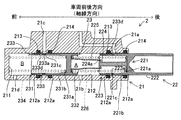
- FIG. 2 is a sectional view showing a configuration of a master cylinder of FIG. 1.
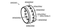
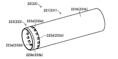
- FIG. 3 is a perspective view illustrating a configuration of a master piston of FIG. 2.
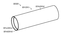
- FIG. 4 is a perspective view illustrating a detailed configuration of a peripheral wall portion that forms the master piston of FIG. 3. It is sectional drawing of the to-be-fitted part of FIG.
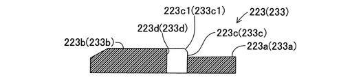
- FIG. 4 is a perspective view showing a detailed configuration of a distal end member constituting the master piston of FIG. 3.
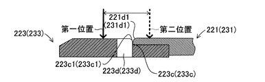
- FIG. 7 is a sectional view of the tip member of FIG. 6. It is sectional drawing which shows the state which attached the front-end member to the peripheral wall part.
- FIG. 10 is a cross-sectional view illustrating a configuration of a master cylinder according to a first modification. It is sectional drawing which shows the state which attached the front-end
- the vehicle brake device 1 includes a master cylinder 2, a brake booster 3, a wheel cylinder 4, a brake actuator 5, and a reservoir tank 6, as shown in FIG.
- the master cylinder 2 includes a cylinder main body 21 and a first master piston 22 and a second master piston 23 as master pistons, as described later in detail.
- the brake booster 3 is, for example, a booster of a negative pressure type, and boosts the pedaling force of the driver and transmits the boosted force to the first master piston 22 and the second master piston 23.
- the wheel cylinder 4 includes a wheel cylinder 41, a wheel cylinder 42, a wheel cylinder 43, and a wheel cylinder 44 provided for each wheel.
- Each of the wheel cylinders 41 to 44 is connected to the master cylinder 2 via a brake actuator 5 (hereinafter, also simply referred to as “actuator 5”).
- Wheel cylinder 41 is arranged on left rear wheel RL of the vehicle.
- the wheel cylinder 42 is disposed on the right rear wheel RR of the vehicle.
- the wheel cylinder 43 is arranged on the left front wheel FL of the vehicle.
- the wheel cylinder 44 is arranged on the right front wheel FR of the vehicle.
- the wheel cylinder 4 supplies the left rear wheel RL, the right rear wheel RR, and the left front wheel FL. And a braking force is generated on the right front wheel FR.
- the actuator 5 has a pipeline, a solenoid valve, a check valve, and the like provided corresponding to each of the wheel cylinders 41 to 44. Accordingly, when the control device (microcomputer) (not shown) controls the solenoid valve to switch to the open or closed state, the actuator 5 applies the brake fluid pressurized by the master cylinder 2 to each of the wheel cylinders 41 to 44. Or the brake fluid pressurized by a built-in pump is regulated and supplied to each of the wheel cylinders 41 to 44. Since the operation of the actuator 5 is not directly related to the present invention, a detailed description thereof will be omitted.
- the depression force is boosted by the negative pressure type brake booster 3 airtightly connected to the master cylinder 2, and the first master piston in the cylinder body 21 is increased. 22 and the second master piston 23 are pressed.
- the pressed first master piston 22 and second master piston 23 advance forward, for example, in the vehicle front-rear direction (axial direction), and are respectively inserted into the master cylinder 2 (more specifically, the cylinder body 21).
- the brake fluid supplied from the reservoir tank 6 is pressurized.
- a master cylinder pressure is generated, and the master cylinder pressure is supplied (transmitted) to each of the wheel cylinders 41 to 44 via the actuator 5.
- a pump built in the actuator 5 is operated in order to correct the behavior of the vehicle during the operation of the automatic braking function or during running or braking.
- the pump sucks the brake fluid stored in the reservoir tank 6 via the master cylinder 2 and generates a pump pressure by pressurizing the sucked brake fluid.
- the pump pressure is adjusted by the actuator 5 and supplied (transmitted) to each of the wheel cylinders 41 to 44.
- the master cylinder 2 includes a cylinder body 21 that slidably accommodates a first master piston 22 and a second master piston 23 that are master pistons.
- the cylinder body 21 is a closed-end cylindrical cylinder closed at one end and having a bottom 211 and open at one end.
- the brake booster 3 is airtightly connected to the opening side of the cylinder body 21 (see FIG. 1).
- the bottom 211 side of the cylinder main body 21 is referred to as “front”, and the opening side of the cylinder main body 21 is referred to as “rear”.
- the first master piston 22 and the second master piston 23 are in the “first position” where the master cylinder 2 (cylinder main body 21) has not advanced from the original position. is there.
- the first master piston 22 and the second master piston 23 are at the “second position” advanced from the first position.
- a housing groove 212 a formed along the circumferential direction is formed on the inner circumferential surface 212 of the cylinder body 21 so that the first master piston 22 and the second master piston 22 are formed along the axial direction of the cylinder body 21.
- the front receiving groove 212a with respect to each of the first master piston 22 and the second master piston 23 is referred to as a "front receiving groove 212a”
- the accommodation groove 212a on the rear side of each of the 22 and the second master piston 23 is referred to as a "rear accommodation groove 212a".
- a front seal member 213 serving as a seal member is housed in the front housing groove 212a. Further, the rear side sealing member 214 is accommodated in the rear side accommodation groove 212a.
- the front-side seal member 213 and the rear-side seal member 214 are formed of an elastic member (for example, a rubber material), and are, for example, U-shaped cup seals each having an open end. The outer peripheral edges of the front seal member 213 and the rear seal member 214 are in contact with the bottom surface (inner peripheral surface) of the accommodation groove 212a.
- the inner peripheral edge of the front seal member 213 contacts the outer peripheral surface of the distal member 223 and the distal member 233 described later.
- the front seal member 213 allows the flow of brake fluid through the communication passages 223d and 233d, as described later.
- the inner peripheral edge of the front seal member 213 is larger than the tip member 223 of the first master piston 22 and the second master piston 23. It comes into contact with the rear outer peripheral surface.
- the front seal member 213 prohibits the flow of the brake fluid through the communication passages 223d and 233d.
- the inner peripheral edge of the rear seal member 214 is located rearward of the distal ends of the first master piston 22 and the second master piston 23 regardless of the first position and the second position of the first master piston 22 and the second master piston 23. Abuts the outer peripheral surface of Therefore, the rear seal member 214 always prohibits the flow of the brake fluid.
- the first master piston 22 is airtightly connected to the brake booster 3, and is arranged coaxially inside the cylinder body 21 and capable of moving forward and backward along the axial direction (that is, the vehicle longitudinal direction). .
- the first master piston 22 includes a main body 221, a protrusion 222, and a tip member 223.
- the main body part 221 is formed in a bottomed cylindrical shape (hollow shape) having a front end opened at the front end, and has a bottom wall part 221a provided at the rear, and a peripheral wall part 221b connected to the bottom wall part 221a. , Is composed of.
- the protruding portion 222 is a cylindrical portion that protrudes rearward from the end surface of the bottom wall portion 221a of the main body portion 221.
- the protrusion 222 is hermetically accommodated inside the brake booster 3. The rear end of the protruding portion 222 comes into contact with and is pressed against an input member (not shown) of the brake booster 3.
- the distal end member 223 is fitted and fixed (attached) to the distal end of the first master piston 22, more specifically, the peripheral wall portion 221b constituting the main body portion 221.
- the distal end of the peripheral wall portion 221 b is connected to the small-diameter portion having a larger inner diameter than the base end (the bottom wall portion 221 a side) as the small-diameter portion of the peripheral wall portion 221 b.
- the fitted portion 221c is provided on the large diameter portion.
- the fitted portion 221c is formed to have the same inner diameter along the axial direction.
- the distal end member 223 includes an annular fitting portion 223a and an annular portion 223b having a larger diameter than the fitting portion 223a.
- the fitting portion 223a has the same or slightly larger outer diameter than the inner diameter of the fitted portion 221c, and is fitted to the fitted portion 221c provided on the peripheral wall portion 221b by, for example, press fitting. Are combined.
- the fitting portion 223a is formed to have the same outer diameter along the axial direction.
- the annular portion 223b has a larger diameter than the outer diameter of the fitting portion 223a, and has the same outer diameter as the outer diameter of the peripheral wall portion 221b.
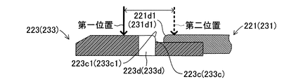
- the annular portion 223b has an end face 223c that stands upright from the fitting portion 223a in a direction orthogonal to the axial direction (hereinafter, this direction is referred to as a “radial direction”). As shown in FIG. 8, the end face 223c can be brought into contact with the tip end face 221d of the peripheral wall part 221b of the main body part 221. Further, as shown in FIG. 7, the outer peripheral edge 223c1 of the end face 223c has a curved shape in a cross section including the axial direction.
- the outer peripheral edge portion 221d1 of the distal end surface 221d of the main body portion 221 (peripheral wall portion 221b) that can contact the end surface 223c also has a curved shape in a cross section including the axial direction, as shown in FIG.
- the annular portion 223b has a plurality of communication passages 223d provided along the circumferential direction of the first master piston 22 (the main body 221).
- the communication passage 223d is a through hole formed along the radial direction as shown in FIGS.
- the communication passage 223d which is a through-hole, is formed along the mold cutting direction.
- the communication passage 223d is formed in a long hole shape along the circumferential direction.
- the communication passage 223d is formed so that a part of the end face 223c of the annular portion 223b is cut off to communicate the outer periphery and the inner periphery of the annular portion 223b.
- the cutout portion comes into contact with the distal end surface 221 d, so that it can be viewed from the radial direction. It is designed to be completed as a U-shaped flow path (through hole).
- the communication passage 223d has a thick solid line when the first master piston 22 is at the first position in a state where the distal end member 223 is attached to the distal end of the main body 221 (peripheral wall 221b). It is located behind the seal line of the front seal member 213 indicated by the arrow. Thereby, the communication passage 223d allows the flow of the brake fluid as described later.
- the first master piston 22 is advanced from the first position and is at the second position, the first master piston 22 is located forward of the seal line of the front seal member 213 indicated by a thick broken arrow in FIG. As a result, the communication passage 223d inhibits (blocks) the flow of the brake fluid, as described later.
- a pin member 224 is provided inside the main body 221. As shown in FIG. 2, the pin member 224 extends inside the main body 221 of the first master piston 22 along the axial direction (that is, the vehicle longitudinal direction).
- the pin member 224 has a large-diameter locking portion 224a that allows the sleeve member 225 to relatively move along the axial direction (that is, the vehicle front-rear direction) and prevents the sleeve member 225 from being pulled forward.
- the sleeve member 225 holds the spring 226, which is an elastic member, together with the pin member 224 (or the bottom wall portion 221a) so as to be able to expand and contract.
- the spring 226 is housed between the inside of the peripheral wall 221 b of the main body 221 and the outer periphery of the pin member 224.
- the spring 226 has one end abutting on a flange portion (or a bottom wall portion 221a) provided on the base end side of the pin member 224, and the other end having a second master piston 23 (more specifically, a bottom wall described later). It is housed so as to abut the flange of the sleeve member 225 abutting behind the part 231a).
- the spring 226 moves the first master piston 22 advanced in the axial direction (that is, the vehicle longitudinal direction) in the axial direction (that is, the vehicle longitudinal direction) so as to increase the hydraulic pressure of a first hydraulic chamber A described later.
- a biasing force is applied so as to retreat along.
- the second master piston 23 is disposed inside the cylinder body 21 so as to be able to move forward and backward along the axial direction (that is, the vehicle longitudinal direction) in front of the first master piston 22.
- the second master piston 23 includes a main body 231, a protrusion 232, and a tip member 233.
- the main body portion 231 is formed in a bottomed cylindrical shape (hollow shape) having an opening at the end facing the bottom portion 211 of the cylinder main body 21, and is connected to the bottom wall portion 231 a provided at the rear and the bottom wall portion 231 a. And a peripheral wall portion 231b.
- the peripheral wall portion 231b of the main body portion 231 is fitted to the distal end member 233, so that the peripheral wall portion 231b has a smaller diameter than the base end (the bottom wall portion 231a side) of the peripheral wall portion 231b.
- the fitted portion 231c is provided at the large diameter portion which is provided continuously at the small diameter portion with a large inside diameter and located at the tip.
- the fitted portion 231c is formed so as to have the same inner diameter along the axial direction.
- the outer peripheral edge 231d1 of the distal end surface 231d of the main body 231 also has a curved shape in a cross section including the axial direction, as shown in FIG.
- the protruding portion 232 is a cylindrical portion protruding rearward from an end surface of the bottom wall portion 231a of the main body portion 231.
- the tip member 233 has the same configuration as the tip member 223 provided on the first master piston 22. Accordingly, as shown in FIGS. 3 and 6 to 8, the fitting portion 233a, the annular portion 233b, the end surface 233c, the outer peripheral edge portion 233c1, and the communication path 233d of the tip member 233 form the fitting portion 223a of the tip member 223. It corresponds to the portion 223b, the end face 223c, the outer peripheral edge 223c1, and the communication passage 223d, and the description thereof will be omitted.
- a spring 234 is housed inside the peripheral wall part 231b of the main body part 231.
- the spring 234 is accommodated such that one end thereof contacts the bottom wall portion 231 a of the second master piston 23 and the other end thereof contacts the bottom portion 211 of the cylinder body 21.
- the spring 234 moves the second master piston 23 advanced in the axial direction (ie, the vehicle longitudinal direction) in the axial direction (ie, the vehicle longitudinal direction) so as to increase the hydraulic pressure of the second hydraulic chamber B described later.
- a biasing force is applied so as to retreat along.
- the first hydraulic chamber A is defined by the bottom wall 231 a and the inner surface of the protrusion 232 forming the second master piston 23, and the rear seal member 214 corresponding to the second master piston 23.
- the communication passage 223d of the tip member 223 communicates with the first hydraulic chamber A.
- the member 213 defines a “second hydraulic chamber B”.
- the communication passage 233d of the tip member 233 communicates with the second hydraulic chamber B.
- Port 21a, port 21b, port 21c and port 21d are formed in the cylinder body 21 of the master cylinder 2 to communicate the inside and the outside.
- each of the ports 21a to 21d will be specifically described.
- the port 21a is formed between the front seal member 213 and the rear seal member 214 corresponding to the first master piston 22, and communicates the reservoir tank 6 with the inside of the cylinder body 21. doing.
- the port 21a can communicate with the first hydraulic chamber A via a communication passage 223d formed in the distal end member 223 of the first master piston 22.
- the port 21b communicates the first hydraulic chamber A with the actuator 5 (see FIG. 1).
- the port 21 c is formed between the front seal member 213 and the rear seal member 214 corresponding to the second master piston 23, and communicates the reservoir tank 6 with the inside of the cylinder body 21. doing.
- the port 21c can communicate with the second hydraulic chamber B via a communication passage 233d formed in the distal end member 233 of the second master piston 23.
- the port 21d communicates the second hydraulic chamber B with the actuator 5 (see FIG. 1).
- the hydraulic pressures of the first hydraulic pressure chamber A and the second hydraulic pressure chamber B become lower than the reference hydraulic pressure. Pressure.
- the first master piston 22 and the second master piston 23 are at the first position (original position).
- the communication path 223d of the tip member 223 and the communication path 233d of the tip member 233 that is, the contact position is It is located behind the seal line of the member 213 (indicated by the thick solid line arrow in FIG. 8).
- the communication passage 223d communicates with the reservoir tank 6 via the port 21a, and the communication passage 233d communicates with the reservoir via the port 21c. It communicates with the tank 6.
- the communication passage 223d of the tip member 223 communicates with a first hydraulic chamber A formed inside the master cylinder 2.
- the communication passage 233d of the tip member 233 communicates with a second hydraulic chamber B formed inside the master cylinder 2.
- the pump sucks the brake fluid from the first hydraulic chamber A and the second hydraulic chamber B of the master cylinder 2 by the automatic brake function, so that the brake fluid flows from the reservoir tank 6 through the communication passages 223d and 233d. Flows smoothly by the necessary and sufficient amount. Therefore, the pump can quickly increase the pump pressure by quickly sucking a necessary and sufficient amount of brake fluid.
- each of the wheel cylinders 41 to 44 can generate a braking force corresponding to the supplied (transmitted) pump pressure to each of the wheels RL to FR with good responsiveness.
- the first master piston 22 and the second master piston 23 are moved from the first position by the driver's depression force on the brake pedal 7 and the boosting force of the brake booster 3. Advance to the second position.
- the communication path 223d of the tip member 223 and the communication path 233d of the tip member 233 are indicated by a thick chain line in FIG. Is located forward of the seal line of the front seal member 213 indicated by the arrow.
- the front-side seal member 213 has an inner peripheral edge that extends over the entire outer periphery of the main body portion 221 (peripheral wall portion 221b) of the first master piston 22 and an outer peripheral surface of the main body portion 231 (peripheral wall portion 231b) of the second master piston 23. Contact the surface and seal. Accordingly, the communication between the communication passage 223d and the port 21a and the communication between the communication passage 233d and the port 21c are interrupted, that is, the communication between the first hydraulic chamber A and the reservoir tank 6 and the communication between the second hydraulic chamber B and Since the communication with the reservoir tank 6 is interrupted, the hydraulic pressure in the first hydraulic chamber A and the second hydraulic chamber B becomes higher than the reference hydraulic pressure.
- each of the wheel cylinders 41 to 44 can generate a braking force on the wheels RL to FR according to the supplied (transmitted) master cylinder pressure.
- the inner peripheral edge of the seal member 213 determines the contact position between the end face 223c of the tip member 223 and the tip face 221d of the main body 221 and the contact position between the end face 233c of the tip member 233 and the tip face 231d of the main body 231. pass.
- the outer peripheral edge portion 223c1 of the end surface 223c and the outer peripheral edge portion 221d1 of the tip end surface 221d have curved cross-sectional shapes.
- the outer peripheral edge portion 233c1 of the end surface 233c and the outer peripheral edge portion 231d1 of the distal end surface 231d have curved cross-sectional shapes.
- the inner peripheral edge of the front seal member 213 has the outer peripheral edge portions 223c1 and 221d1 and The load due to contact with the outer peripheral edge portions 233c1 and 231d1 can be reduced. Thereby, the front side sealing member 213 can maintain good sealing performance.
- the master cylinder 2 of the above embodiment is slidably housed in the cylinder body 21 along the axial direction of the cylinder body 21 (vehicle longitudinal direction) inside the cylinder body 21.
- the cylinder body 21 includes a first master piston 22 and a second master piston 23 serving as master pistons, and has a bottom 211 at one end, and is open at the other end.
- the first master piston 22 and the second master piston 23 have a bottom wall 221a and a bottom wall 221a that define a first hydraulic chamber A and a second hydraulic chamber B, which are hydraulic chambers, together with the inner peripheral surface 212 of the cylinder body 21.
- the master cylinder 2 is provided in the cylinder body 21 and communicates with the reservoir tank 6 for storing brake fluid, which is a hydraulic fluid, through ports 21 a and 21 c, and ends of the first master piston 22 and the second master piston 23.
- brake fluid which is a hydraulic fluid
- a sealing member disposed between the portion and the ports 21a and 21c to seal between the inner peripheral surface 212 of the cylinder body 21 and the outer peripheral surfaces including the distal end portions of the first master piston 22 and the second master piston 23.
- the first master piston 22 and the second master piston 23 have tip members 223, 233 attached to the tips of the peripheral wall portions 221b, 231b, respectively.
- the tip members 223, 233 are attached to the tip ends of the peripheral wall portions 221b, 231b.
- 233 are fitted along the axial direction, and the tip members 223 and 233 are provided with fitting portions 223a and 233a fitted to the fitted portions 221c and 231c.
- the end faces 223c, 233c which are larger in diameter than the outer diameters of the fitting parts 223a, 233a, and which stand upright from the fitting parts 223a, 233a in the direction orthogonal to the axial direction, have the end faces 221d, 221d of the peripheral wall parts 221b, 231b.
- annular portions 223b and 233b provided so as to be in contact with each other, and the distal ends of the peripheral walls 221b and 231b and the annular portions 223b and 233b.
- the port 21a, the first hydraulic chamber A, the port 21c and the second When the first master piston 22 and the second master piston 23 are in the second position advanced from the first position with respect to the cylinder main body 21 with respect to the cylinder body 21, the port 21a is communicated with the two hydraulic chambers B by the front seal member 213.
- a plurality of communication ports provided along the circumferential direction of the first master piston 22 and the second master piston 23 so that communication between the first hydraulic chamber A and the port 21c and the second hydraulic chamber B is interrupted. It has passages 223d and 233d.
- the peripheral wall portions 221b and 231b of the first master piston 22 and the second master piston 23 are composed of a large diameter portion having a large diameter and a small diameter portion (base end) having a small diameter, and a large diameter portion is provided.
- the fitting portions 221c and 231c are located at the distal ends of the peripheral wall portions 221b and 231b and connected to the small diameter portion, and the fitting portions 223a and 233a of the distal end members 223 and 233 are fitted.
- the tip members 223 and 233 can be assembled by fitting the fitting portions 223a and 233a to the fitted portions 221c and 231c provided at the tips of the peripheral wall portions 221b and 231b.
- the assembling structure at the distal ends of the distal end members 223 and 233 and the peripheral wall portions 221b and 231b can be simplified, and as a result, it can be assembled using general-purpose tools and equipment, and the assembling property is improved. be able to.
- by improving the assemblability it is possible to reduce the manufacturing cost when manufacturing the master cylinder 2.
- the tip members 223 and 233 have the communication passages 223d and 233d, the flow of the hydraulic fluid inside the master cylinder 2 can be improved.
- the outer peripheral edges 223c1 and 233c1 of the end surfaces 223c and 233c of the annular portions 223b and 233b and the outer peripheral edges 221d1 and 231d1 of the distal end surfaces 221d and 231d of the peripheral wall portions 221b and 231b have curved shapes in a cross section including the axial direction. is there. According to this, the load generated on the inner peripheral edge of the front seal member 213 can be reduced by coming into contact with the outer peripheral edges 223c1, 221d1 and the outer peripheral edges 233c1, 231d1. Therefore, even when the first master piston 22 and the second master piston 23 move between the first position and the second position, the front seal member 213 can maintain good sealing performance. .
- the communication passages 223d and 233d may be through holes formed in a radial direction orthogonal to the axial direction. According to this, the communication paths 223d and 233d can be formed very easily in the tip members 223 and 233, and the flow of the hydraulic fluid inside the master cylinder 2 can be improved.
- the first master piston 22 in the master cylinder 2 has the pin member 224 for holding the sleeve member 225 so as to be relatively movable.
- the distal end member 223 may hold the sleeve member 225 so as to be relatively movable.
- a locking portion 223e protruding along the circumferential direction is provided on the inner peripheral surface of the tip member 223.
- the locking portion 223e locks with the locked portion 225a provided on the sleeve member 225, thereby prohibiting the sleeve member 225 from relatively moving forward along the axial direction.
- the locking portion 223e allows the sleeve member 225 to relatively move rearward along the axial direction. That is, the locking portion 223e provided on the tip member 223 exhibits the same function as the pin member 224 and the locking portion 224a in the above embodiment.
- the locking member 223e and the locked portion 225a are engaged by inserting the sleeve member 225 from the fitting portion 223a side of the tip member 223. To stop. Then, while inserting the spring 226 into the inside of the sleeve member 225 and compressing the spring 226, the tip member 223 is fitted to the tip of the main body 221 (peripheral wall portion 221b) of the first master piston 22, for example, by press-fitting. And fix it.
- the sleeve member 225 can hold the spring 226 without falling off from the tip member 223 by the locking portion 223e of the tip member 223. Then, in a state where the first master piston 22 to which the distal end member 223 is fixed is assembled inside the cylinder body 21, when the first master piston 22 advances from the first position to the second position, the sleeve member 225 is The spring 226 is compressed by abutting against the bottom wall portion 231a of the second master piston 23 and moving relative to the tip member 223. As a result, the spring 226 biases the first master piston 22 rearward. be able to. Therefore, in the assembling work of the master cylinder 2, extremely good workability can be secured.
- the first master piston in a state where the sleeve member 225 and the spring 226 are assembled in manufacturing. 22 can be made uniform in length. As a result, it is possible to reduce variations in the stepping amount of the brake pedal 7 and the generated master cylinder pressure. Further, since the pin member 224 can be omitted, the manufacturing cost can be reduced.
- the communication path 223d is formed in the annular portion 223b of the tip member 223, and the communication path 233d is formed in the annular portion 233b of the tip member 233.
- a flow path 221e may be provided in the main body 221 (peripheral wall 221b) and a flow path 231e may be provided in the main body 231 (peripheral wall 221b).
- the end members 223 and 233 are assembled to the ends of the main bodies 221 and 231, and the end surface 223c and the end surface 221d come into contact with each other, and the end surface 233c and the end surface 231d come into contact with each other.
- the communication path 223d and the communication path 233d are completed. Therefore, also in this case, the same effect as the above embodiment can be obtained.
- the front seal member 213 does not pass through the contact position T. Therefore, even when the cross-sectional shape of the outer peripheral edges 223c1, 233c1, 221d1, and 231d1 is not a curved shape, a load is not applied to the inner peripheral edge of the front seal member 213, and the front seal member 213 is a good seal. Sex can be maintained.
- the brake fluid flowing in the communication paths 223d and 233d flows to the communication paths 223d and 233d through the gap.
- the gap is partitioned from the inside of the main bodies 221 and 231 by the fitting portions 223a and 233a of the tip members 223 and 233, the brake fluid flowing in the gap flows toward the communication passages 223d and 233d. Therefore, also in the third modification, the same effect as in the above embodiment can be obtained.
- the communication passages 223d and 233d of the tip members 223 and 233 are formed as elongated through holes extending in the circumferential direction. Thereby, molding by a mold is facilitated.
- through holes formed radially from the centers of the tip members 223 and 233 may be used as the communication passages 223d and 233d.
- the communication passages 223d and 233d can be provided evenly along the circumferential direction of the tip members 223 and 233, as shown in FIG.
- the communication passages 223d and 233d of the tip members 223 and 233 are formed as elongated through holes extending in the circumferential direction.
- a plurality of communication paths 223f and 233f of grooves extending in the axial direction can be provided along the circumferential direction.
- the communication passages 223f and 233f are respectively connected to the first hydraulic chamber A in a state where the tip members 223 and 233 are fitted and fixed to the tips of the main bodies 221 and 231 (peripheral walls 221b and 231b).
- the second hydraulic chamber B is also connected to the first hydraulic chamber A in a state where the tip members 223 and 233 are fitted and fixed to the tips of the main bodies 221 and 231 (peripheral walls 221b and 231b).
- the fitting portions 223a and 233a of the tip members 233 and 233 are attached to the fitted portions 221c and 231c of the main body portions 221 and 231 (peripheral wall portions 221b and 231b), for example. It was fitted and fixed by press fitting.
- the fitting portions 223a and 233a may be fitted to the fitted portions 221c and 231c, and then firmly fixed by, for example, bonding.
- the fitting sections 223a and 233a and the fitting sections 221c and 231c can have a circular cross section in the radial direction.
- the tip members 233 and 233 can be easily fixed and assembled (attached) to the tips of the main bodies 221 and 231 (peripheral walls 221b and 231b).
- the fitting portions 223a and 233a of the tip members 233 and 233 are attached to the fitted portions 221c and 231c of the main body portions 221 and 231 (peripheral wall portions 221b and 231b), for example. It was fitted and fixed by press fitting.
- the fitting portions 223a and 233a are elastically deformed and assembled to the fitted portions 221c and 231c by so-called snap fitting. It is also possible to do so. This also allows the tip members 233 and 233 to be easily fixed and assembled to the tips of the main bodies 221 and 231 (peripheral walls 221b and 231b).
- the opening shapes of the communication passages 223d and 233d are rectangular.
- the shape of the openings of the communication passages 223d and 233d is not particularly limited, and it goes without saying that a round shape, an elliptical shape, or the like can be adopted.
Landscapes
- Engineering & Computer Science (AREA)
- Transportation (AREA)
- Mechanical Engineering (AREA)
- Transmission Of Braking Force In Braking Systems (AREA)
Abstract
マスタピストンは、先端部材(223),(233)を有している。先端部材(223),(233)は、マスタピストンの被嵌合部に対して嵌合される嵌合部(223a),(233a)と、環状部(223b),(233b)と、を有し、環状部(223b),(233b)に、周方向に沿って設けられた複数の連通路(223d),(233d)を有する。
Description
本発明は、マスタシリンダに関する。
従来から、例えば、下記特許文献1に開示されたマスタシリンダが知られている。この従来のマスタシリンダは、ハウジングと、ハウジング内を移動可能であり本体及び環状の制御要素を有する少なくとも一つのピストンと、ピストンを液圧室から密封するシール部材と、制御要素に設けられていて液圧室と加圧されていないリザーバタンクとを接続可能な制御通路と、を備えている。そして、従来のマスタシリンダにおいて、制御要素は、ピストンの本体に設けられた外部溝内に配置されるようになっている。
近年、車両においては、運転者によるブレーキ操作に拘わらず、自動的に車両を制動する自動ブレーキ機能が搭載される場合がある。この自動ブレーキ機能においては、マスタシリンダよりも下流側に設けられたポンプによってマスタシリンダの液圧室の作動液が吸引されて、吸引された作動液が加圧されて各車輪のホイールシリンダに供給される。このような自動ブレーキ機能においては、ポンプがマスタシリンダから作動液を速やかに且つ必要十分な量を吸引して、制動力を発生させる際の応答性を高める必要がある。
ところで、上記従来のマスタシリンダにおいては、ポンプが作動液を吸引する、所謂、吸い込み性を確保するために、ピストンを本体と制御通路を有する制御要素とから構成し、本体に設けた外部溝内に制御要素を組み付けるようになっている。この場合、環状の制御要素を一旦拡径してから本体の外周溝に取り付けるような専用の工具や設備、工程が必要であり、組み付け性を改善する余地がある。
本発明は、上記課題を解決するためになされたものである。即ち、本発明の目的は、組み付け容易な構造を有して内部における作動液の流れを改善することができるマスタシリンダを提供することにある。
上記の課題を解決するため、本発明に係るマスタシリンダは、一端が閉塞し且つ他端が開口したシリンダ本体と、シリンダ本体の内部にシリンダ本体の軸線方向に沿って摺動可能に収容され、且つ、シリンダ本体の内周面と共に液圧室を区画する底壁部及び底壁部に連結された周壁部を有する有底筒状のマスタピストンと、シリンダ本体に設けられて、作動液を貯留するリザーバタンクに連通するポートと、マスタピストンの先端部分とポートとの間に配置されて、シリンダ本体の内周面とマスタピストンの先端部分を含む外周面との間をシールするシール部材と、を備えたマスタシリンダであって、マスタピストンは、周壁部の先端に取り付けられる先端部材を有しており、周壁部の先端には、先端部材が軸線方向に沿って嵌合される被嵌合部が設けられ、先端部材は、被嵌合部に対して嵌合される嵌合部と、嵌合部の外径よりも大径であり、軸線方向に直交する方向に嵌合部から立設された端面が周壁部の先端面と当接可能に設けられた環状部と、を有し、周壁部の先端及び環状部の少なくとも一方に、マスタピストンがシリンダ本体に対して第一位置にある場合にポートと液圧室とを連通し、マスタピストンがシリンダ本体に対して第一位置よりも前進した第二位置にある場合にシール部材によりポートと液圧室との連通が遮断されるように、マスタピストンの周方向に沿って設けられた複数の連通路を有する。
これによれば、先端部材は、嵌合部を周壁部の先端に設けられた被嵌合部に挿入して嵌合することにより組み付けることができる。このため、先端部材及び周壁部の先端における組み付け構造を簡素化することができ、その結果、汎用の工具や設備を利用して組み付けることができて、組み付け性を改善することができる。又、先端部材が連通路を有することにより、マスタシリンダの内部における作動液の流れを改善することができる。
以下、本発明の実施形態について図面を参照しながら説明する。尚、以下の実施形態及び各変形例の相互において、互いに同一もしくは均等である部分には、図中、同一符号を付してある。又、説明に用いる各図は概念図であり、各部の形状は必ずしも厳密なものではない場合がある。
本実施形態における車両のブレーキ装置1は、図1に示すように、マスタシリンダ2、ブレーキブースタ3、ホイールシリンダ4、ブレーキアクチュエータ5及びリザーバタンク6を備えている。マスタシリンダ2は、後に詳述するように、シリンダ本体21、及び、マスタピストンとしての第一マスタピストン22及び第二マスタピストン23と、を含んで構成されている。ブレーキブースタ3は、例えば、負圧式の倍力装置であり、運転者による踏力を倍力して第一マスタピストン22及び第二マスタピストン23に伝達する。
ホイールシリンダ4は、各輪に設けられたホイールシリンダ41、ホイールシリンダ42、ホイールシリンダ43及びホイールシリンダ44から構成される。各ホイールシリンダ41~44は、ブレーキアクチュエータ5(以下、単に「アクチュエータ5」とも称呼する。)を介して、マスタシリンダ2に接続されている。ホイールシリンダ41は、車両の左後輪RLに配置されている。ホイールシリンダ42は、車両の右後輪RRに配置されている。ホイールシリンダ43は、車両の左前輪FLに配置されている。ホイールシリンダ44は、車両の右前輪FRに配置されている。これにより、ホイールシリンダ4は、作動液としてのブレーキフルードがマスタシリンダ2又は後述するポンプによって加圧されてアクチュエータ5を介して供給されると、左後輪RL、右後輪RR、左前輪FL及び右前輪FRに制動力を発生させる。
アクチュエータ5は、詳細な図示を省略するが、各ホイールシリンダ41~44に対応して設けられた管路、電磁弁及び逆止弁等を有している。これにより、アクチュエータ5は、図示を省略する制御装置(マイクロコンピュータ)によって電磁弁が連通状態又は遮断状態に切替制御されると、マスタシリンダ2によって加圧されたブレーキフルードを各ホイールシリンダ41~44に供給したり、内蔵するポンプによって加圧されたブレーキフルードを調圧して各ホイールシリンダ41~44に供給したりする。尚、アクチュエータ5の作動については、本発明に直接関係しないので、その詳細な説明を省略する。
車両のブレーキ装置1においては、運転者がブレーキペダル7を踏み込むと、マスタシリンダ2に気密的に連結された負圧式のブレーキブースタ3により踏力が倍力され、シリンダ本体21内の第一マスタピストン22及び第二マスタピストン23が押圧される。押圧された第一マスタピストン22及び第二マスタピストン23は、例えば、車両前後方向(軸線方向)にて前方に向けて前進し、それぞれ、マスタシリンダ2(より詳しくはシリンダ本体21)の内部にリザーバタンク6から供給されたブレーキフルードを加圧する。これにより、マスタシリンダ2においては、マスタシリンダ圧が発生し、マスタシリンダ圧がアクチュエータ5を介して各ホイールシリンダ41~44に供給(伝達)される。
又、車両のブレーキ装置1においては、例えば、自動ブレーキ機能の作動時や、走行中又は制動時の車両の挙動を修正するために、アクチュエータ5に内蔵したポンプを作動させる。これにより、ポンプは、例えば、自動ブレーキ機能の作動時においては、マスタシリンダ2を介してリザーバタンク6に貯留されているブレーキフルードを吸引し、吸引したブレーキフルードを加圧してポンプ圧を発生させる。そして、ポンプ圧は、アクチュエータ5によって調圧されて、各ホイールシリンダ41~44に供給(伝達)される。
(1.マスタシリンダ2の構成の詳細)
マスタシリンダ2は、図2に示すように、マスタピストンである第一マスタピストン22及び第二マスタピストン23を摺動可能に収容するシリンダ本体21を備えている。シリンダ本体21は、一端が底部211を有して閉塞し且つ一端が開口した有底筒状のシリンダである。シリンダ本体21の開口側には、ブレーキブースタ3が気密的に連結される(図1を参照)。
マスタシリンダ2は、図2に示すように、マスタピストンである第一マスタピストン22及び第二マスタピストン23を摺動可能に収容するシリンダ本体21を備えている。シリンダ本体21は、一端が底部211を有して閉塞し且つ一端が開口した有底筒状のシリンダである。シリンダ本体21の開口側には、ブレーキブースタ3が気密的に連結される(図1を参照)。
ここで、以下の説明では、シリンダ本体21の軸線方向即ち車両前後方向において、シリンダ本体21の底部211側を「前方」とし、シリンダ本体21の開口側を「後方」とする。又、第一マスタピストン22及び第二マスタピストン23は、ブレーキペダル7が操作されていない場合にはマスタシリンダ2(シリンダ本体21)に対して原位置から前進していない「第一位置」にある。更に、第一マスタピストン22及び第二マスタピストン23は、ブレーキペダル7が操作された場合には第一位置から前進した「第二位置」にある。
図2に示すように、シリンダ本体21の内周面212には、周方向に沿って形成された収容溝212aが、シリンダ本体21の軸線方向に沿って第一マスタピストン22及び第二マスタピストン23のそれぞれに対応して二つずつ、計四つ設けられている。尚、以下の説明において、特に区別する場合、第一マスタピストン22及び第二マスタピストン23のそれぞれに対して前方側の収容溝212aを「前方側収容溝212a」と称呼し、第一マスタピストン22及び第二マスタピストン23のそれぞれに対して後方側の収容溝212aを「後方側収容溝212a」と称呼する。
前方側収容溝212aには、シール部材である前方側シール部材213が収容される。又、後方側収容溝212aには、後方側シール部材214が収容される。前方側シール部材213及び後方側シール部材214は、弾性部材(例えば、ゴム材料)から形成されており、例えば、一端が開放された断面形状としてU字状のカップシールである。前方側シール部材213及び後方側シール部材214の外周縁は、収容溝212aの底面(内周面)と当接する。
前方側シール部材213の内周縁は、第一マスタピストン22及び第二マスタピストン23が第一位置にある場合には、後述する先端部材223及び先端部材233における外周面と当接する。これにより、前方側シール部材213は、後述するように、連通路223d,233dを介したブレーキフルードの流動を許容する。
又、前方側シール部材213の内周縁は、第一マスタピストン22及び第二マスタピストン23が第二位置にある場合には、第一マスタピストン22及び第二マスタピストン23の先端部材223よりも後方の外周面と当接する。これにより、前方側シール部材213は、連通路223d,233dを介したブレーキフルードの流動を禁止する。
後方側シール部材214の内周縁は、第一マスタピストン22及び第二マスタピストン23の第一位置及び第二位置に拘わらず、第一マスタピストン22及び第二マスタピストン23の先端部分よりも後方の外周面と当接する。従って、後方側シール部材214は、常に、ブレーキフルードの流動を禁止する。
第一マスタピストン22は、ブレーキブースタ3に気密的に連結されており、シリンダ本体21の内部にて同軸的且つ軸線方向(即ち、車両前後方向)に沿って前進及び後進可能に配置されている。第一マスタピストン22は、図2に示すように、本体部221と、突出部222と、先端部材223と、から構成されている。
本体部221は、前方に位置する先端が開口する有底筒状(中空状)に形成されており、後方に設けられた底壁部221aと、底壁部221aに連結された周壁部221bと、から構成されている。突出部222は、本体部221の底壁部221aの端面から後方に突出した円筒状の部分である。突出部222は、ブレーキブースタ3の内部に気密的に収容されている。突出部222の後方端部は、ブレーキブースタ3の図示を省略する入力部材と当接して押圧されるようになっている。
先端部材223は、図3に拡大して示すように、第一マスタピストン22、より詳しくは、本体部221を構成する周壁部221bの先端に嵌合されて固定される(取り付けられる)。このため、周壁部221bの先端には、図4及び図5に示すように、周壁部221bの小径部としての基端(底壁部221a側)よりも内径が大きく小径部に連設された大径部に被嵌合部221cが設けられている。被嵌合部221cは、軸線方向に沿って、内径が同一となるように形成される。
先端部材223は、図6及び図7に示すように、環状の嵌合部223aと、嵌合部223aよりも大径の環状部223bと、を備えている。嵌合部223aは、被嵌合部221cの内径に比べて同一又は僅かに大きな外径を有しており、周壁部221bに設けられた被嵌合部221cに対して、例えば、圧入により嵌合される。嵌合部223aは、図7に示すように、軸線方向に沿って、外径が同一となるように形成される。
環状部223bは、嵌合部223aの外径よりも大径であり、且つ、周壁部221bの外径と等しい外径を有している。環状部223bは、軸線方向に直交する方向(以下、この方向を「径方向」と称呼する。)に嵌合部223aから立設された端面223cを有している。端面223cは、図8に示すように、本体部221の周壁部221bの先端面221dと当接可能とされている。又、端面223cの外周縁部223c1は、図7に示すように、軸線方向を含む断面において曲線状となる。ここで、端面223cと当接可能な本体部221(周壁部221b)の先端面221dの外周縁部221d1も、図5に示すように、軸線方向を含む断面において曲線状となる。
又、環状部223bは、第一マスタピストン22(本体部221)の周方向に沿って設けられた複数の連通路223dを有している。連通路223dは、図6及び図7に示すように、径方向に沿って形成された貫通孔である。ここで、先端部材223が樹脂材料を用いて射出成形によって成形される場合、貫通孔である連通路223dは型割方向に沿って形成される。この場合、後述するように、ブレーキフルードの流れをスムーズにするために、図6に示すように、連通路223dは、周方向に沿って長孔状に形成される。
連通路223dは、図6及び図7に示すように、環状部223bの端面223cの一部を切り欠いて環状部223bの外周と内周とを連通するように形成される。これにより、図8に示すように、先端部材223が本体部221(周壁部221b)の先端に組み付けられた状態で、切り欠かれた部分が先端面221dと当接することにより、径方向から見てロ字状の流路(貫通孔)として完成するようになっている。
連通路223dは、図8に示すように、先端部材223が本体部221(周壁部221b)の先端に組み付けられた状態において、第一マスタピストン22が第一位置にある場合には、太実線の矢印により示す前方側シール部材213のシール線よりも後方になる。これにより、連通路223dは、後述するように、ブレーキフルードの流れを許容する。又、第一マスタピストン22が第一位置よりも前進して第二位置にある場合には、図8にて太破線の矢印により示す前方側シール部材213のシール線よりも前方になる。これにより、連通路223dは、後述するように、ブレーキフルードの流れを禁止(遮断)する。
又、本体部221の内部には、ピン部材224が設けられている。ピン部材224は、図2に示すように、第一マスタピストン22の本体部221の内部にて、軸線方向(即ち、車両前後方向)に沿って延設されている。ピン部材224は、スリーブ部材225を軸線方向(即ち、車両前後方向)に沿って相対移動可能とすると共にスリーブ部材225の前方への抜けを防止する大径の係止部224aを有している。スリーブ部材225は、ピン部材224(又は、底壁部221a)と共に弾性部材であるスプリング226を伸縮可能に保持するものである。
スプリング226は、本体部221の周壁部221bの内部とピン部材224の外周との間に収容されている。スプリング226は、一端がピン部材224の基端側に設けられるフランジ部に(又は、底壁部221a)に当接し、且つ、他端が第二マスタピストン23(より詳しくは、後述する底壁部231a)の後方に当接するスリーブ部材225のフランジ部に当接するように収容されている。スプリング226は、後述する第一液圧室Aの液圧を増大させるように軸線方向(即ち、車両前後方向)に沿って前進した第一マスタピストン22を軸線方向(即ち、車両前後方向)に沿って後退させるように付勢力を付与する。
第二マスタピストン23は、シリンダ本体21の内部において、第一マスタピストン22の前方にて同軸的且つ軸線方向(即ち、車両前後方向)に沿って前進及び後進可能に配置されている。第二マスタピストン23は、図2に示すように、本体部231と、突出部232と、先端部材233と、から構成されている。
本体部231は、シリンダ本体21の底部211に対向する先端が開口する有底筒状(中空状)に形成されており、後方に設けられた底壁部231aと、底壁部231aに連結された周壁部231bと、から構成されている。又、本体部231の周壁部231bは、先端部材233と嵌合するために、図4及び図5に示すように、周壁部231bの小径部としての基端(底壁部231a側)よりも内径が大きく小径部に連設されて先端に位置する大径部に被嵌合部231cが設けられている。被嵌合部231cは、軸線方向に沿って、内径が同一となるように形成される。尚、本体部231(周壁部231b)の先端面231dの外周縁部231d1も、図5に示すように、軸線方向を含む断面において曲線状となる。突出部232は、本体部231の底壁部231aの端面から後方に突出した円筒状の部分である。
先端部材233は、第一マスタピストン22に設けられる先端部材223を同一の構成を有する。従って、先端部材233における嵌合部233a、環状部233b、端面233c、外周縁部233c1、連通路233dは、図3及び図6~8に示すように、先端部材223における嵌合部223a、環状部223b、端面223c、外周縁部223c1、連通路223dに対応するものであり、その説明を省略する。
更に、本体部231の周壁部231bの内部には、スプリング234が収容されている。スプリング234は、一端が第二マスタピストン23の底壁部231aに当接し、且つ、他端がシリンダ本体21の底部211に当接するように収容されている。スプリング234は、後述する第二液圧室Bの液圧を増大させるように軸線方向(即ち、車両前後方向)に沿って前進した第二マスタピストン23を軸線方向(即ち、車両前後方向)に沿って後退させるように付勢力を付与する。
ここで、第一マスタピストン22の本体部221を形成する底壁部221a及び周壁部221bの内面と、シリンダ本体21の内周面212と、第一マスタピストン22に対応する前方側シール部材213と、第二マスタピストン23を形成する底壁部231a及び突出部232の内面と、第二マスタピストン23に対応する後方側シール部材214と、によって「第一液圧室A」が区画される。そして、先端部材223の連通路223dは、第一液圧室Aと連通する。
又、第二マスタピストン23の本体部231を形成する底壁部231a及び周壁部231bの内面と、シリンダ本体21の内周面212及び底部211と、第二マスタピストン23に対応する前方側シール部材213と、によって「第二液圧室B」が区画される。そして、先端部材233の連通路233dは、第二液圧室Bと連通する。
マスタシリンダ2のシリンダ本体21には、内部と外部とを連通するポート21a、ポート21b、ポート21c及びポート21dが形成されている。以下、各ポート21a~ポート21dを具体的に説明する。
ポート21aは、図2に示すように、第一マスタピストン22に対応する前方側シール部材213及び後方側シール部材214の間に形成されており、リザーバタンク6とシリンダ本体21の内部とを連通している。そして、ポート21aは、第一マスタピストン22の先端部材223に形成された連通路223dを介して第一液圧室Aに連通可能となっている。ポート21bは、第一液圧室Aとアクチュエータ5(図1を参照)とを連通する。
ポート21cは、図2に示すように、第二マスタピストン23に対応する前方側シール部材213及び後方側シール部材214の間に形成されており、リザーバタンク6とシリンダ本体21の内部とを連通している。そして、ポート21cは、第二マスタピストン23の先端部材233に形成された連通路233dを介して第二液圧室Bに連通可能となっている。ポート21dは、第二液圧室Bとアクチュエータ5(図1を参照)とを連通する。
(2.マスタシリンダ2の作動について)
次に、マスタシリンダ2の作動について具体的に説明する。車両のブレーキ装置1が自動ブレーキ機能により作動する場合、アクチュエータ5に内蔵されたポンプは、第一液圧室A及び第二液圧室Bに存在しているブレーキフルードを吸引する。そして、ポンプはブレーキフルードをポンプ圧まで加圧し、アクチュエータ5が調圧して各ホイールシリンダ41~44に供給(伝達)する。これにより、各ホイールシリンダ41~44は、それぞれ、対応する車輪RL~FRに制動力を発生させる。
次に、マスタシリンダ2の作動について具体的に説明する。車両のブレーキ装置1が自動ブレーキ機能により作動する場合、アクチュエータ5に内蔵されたポンプは、第一液圧室A及び第二液圧室Bに存在しているブレーキフルードを吸引する。そして、ポンプはブレーキフルードをポンプ圧まで加圧し、アクチュエータ5が調圧して各ホイールシリンダ41~44に供給(伝達)する。これにより、各ホイールシリンダ41~44は、それぞれ、対応する車輪RL~FRに制動力を発生させる。
このように、マスタシリンダ2の下流側に配置されたポンプがブレーキフルードを吸引すると、第一液圧室A及び第二液圧室Bの液圧は基準液圧よりも低下し、例えば、負圧になる。ところで、自動ブレーキ機能によってポンプが作動する場合、第一マスタピストン22及び第二マスタピストン23は、第一位置(原位置)にある。第一マスタピストン22及び第二マスタピストン23が第一位置にある場合、図8に示すように、先端部材223の連通路223d及び先端部材233の連通路233d即ち当接位置は、前方側シール部材213のシール線(図8にて太実線の矢印により示す)よりも後方に位置する。これにより、第一マスタピストン22及び第二マスタピストン23が第一位置にある場合には、連通路223dはポート21aを介してリザーバタンク6と連通し、連通路233dはポート21cを介してリザーバタンク6と連通している。
ところで、先端部材223の連通路223dはマスタシリンダ2の内部に形成された第一液圧室Aと連通している。又、先端部材233の連通路233dはマスタシリンダ2の内部に形成された第二液圧室Bと連通している。これにより、自動ブレーキ機能によりポンプがマスタシリンダ2の第一液圧室A及び第二液圧室Bからブレーキフルードを吸引することにより、連通路223d,233dを介して、リザーバタンク6からブレーキフルードが必要十分な量だけスムーズに流入する。従って、ポンプは必要十分な量のブレーキフルードを速やかに吸引してポンプ圧を増圧することができる。その結果、各ホイールシリンダ41~44は、供給(伝達)されたポンプ圧に応じた制動力を各車輪RL~FRに応答性良く発生させることができる。
ここで、ブレーキペダル7が踏み込み操作される通常ブレーキ時においては、運転者によるブレーキペダル7に対する踏力及びブレーキブースタ3による倍力によって、第一マスタピストン22及び第二マスタピストン23が第一位置から第二位置に前進する。そして、第一マスタピストン22及び第二マスタピストン23が第二位置にある場合には、先端部材223の連通路223d及び先端部材233の連通路233d即ち当接位置は、図8にて太鎖線の矢印により示す前方側シール部材213のシール線よりも前方に位置する。その結果、前方側シール部材213は、内周縁が全周にわたり第一マスタピストン22の本体部221(周壁部221b)の外周面及び第二マスタピストン23の本体部231(周壁部231b)の外周面に接触してシールする。従って、連通路223dとポート21aとの連通及び連通路233dとポート21cとの連通が遮断されるため、即ち、第一液圧室Aとリザーバタンク6との連通及び第二液圧室Bとリザーバタンク6との連通が遮断されるため、第一液圧室A及び第二液圧室Bの液圧が基準液圧よりも増大する。
これにより、第一液圧室A及び第二液圧室Bの液圧は、第一マスタピストン22及び第二マスタピストン23の前進に伴う体積の減少によって増大した状態、即ち、マスタシリンダ圧で適切に維持される。その結果、各ホイールシリンダ41~44は、供給(伝達)されたマスタシリンダ圧に応じた制動力を車輪RL~FRに発生させることができる。
ここで、第一マスタピストン22及び第二マスタピストン23が第一位置から第二位置に前進する場合、及び、第二位置から第一位置まで後進する場合、図8に示すように、前方側シール部材213の内周縁は、先端部材223の端面223cと本体部221の先端面221dとの当接位置、及び、先端部材233の端面233cと本体部231の先端面231dとの当接位置を通過する。ところで、端面223cの外周縁部223c1と先端面221dの外周縁部221d1とは断面形状が曲線とされている。同様に、端面233cの外周縁部233c1と先端面231dの外周縁部231d1とは断面形状が曲線とされている。
従って、第一マスタピストン22及び第二マスタピストン23が、第一位置と第二位置との間を移動した場合であっても、前方側シール部材213の内周縁は外周縁部223c1,221d1及び外周縁部233c1,231d1との接触による負荷を軽減することができる。これにより、前方側シール部材213は、良好なシール性能を維持することができる。
以上の説明からも理解できるように、上記実施形態のマスタシリンダ2は、シリンダ本体21と、シリンダ本体21の内部にてシリンダ本体21の軸線方向(車両前後方向)に沿って摺動可能に収容されたマスタピストンとしての第一マスタピストン22及び第二マスタピストン23と、を備える、シリンダ本体21は、一端が底部211を有して閉塞し且つ他端が開口する。第一マスタピストン22及び第二マスタピストン23は、シリンダ本体21の内周面212と共に液圧室である第一液圧室A及び第二液圧室Bを区画する底壁部221a、底壁部231a及び底壁部221a,231aに連結された周壁部221b、周壁部231bを有する有底筒状である。又、マスタシリンダ2は、シリンダ本体21に設けられて、作動液であるブレーキフルードを貯留するリザーバタンク6に連通するポート21a及びポート21cと、第一マスタピストン22及び第二マスタピストン23の先端部分とポート21a,21cとの間に配置されて、シリンダ本体21の内周面212と第一マスタピストン22及び第二マスタピストン23の先端部分を含む外周面との間をシールするシール部材である前方側シール部材213と、を備える。
そして、第一マスタピストン22及び第二マスタピストン23は、周壁部221b,231bの先端に取り付けられる先端部材223,233を有しており、周壁部221b,231bの先端には、先端部材223,233が軸線方向に沿って嵌合される被嵌合部221c,231cが設けられ、先端部材223,233は、被嵌合部221c,231cに対して嵌合される嵌合部223a,233aと、嵌合部223a,233aの外径よりも大径であり、軸線方向に直交する方向に嵌合部223a,233aから立設された端面223c,233cが周壁部221b,231bの先端面221d,231dと当接可能に設けられた環状部223b,233bと、を有し、周壁部221b,231bの先端及び環状部223b,233bの少なくとも一方である環状部223b,233bに、第一マスタピストン22及び第二マスタピストン23がシリンダ本体21に対して第一位置にある場合にポート21aと第一液圧室A及びポート21cと第二液圧室Bとを連通し、第一マスタピストン22及び第二マスタピストン23がシリンダ本体21に対して第一位置よりも前進した第二位置にある場合に前方側シール部材213によりポート21aと第一液圧室A及びポート21cと第二液圧室Bとの連通が遮断されるように、第一マスタピストン22及び第二マスタピストン23の周方向に沿って設けられた複数の連通路223d,233dを有する。この場合、第一マスタピストン22及び第二マスタピストン23の周壁部221b,231bは、内径が大径である大径部及び小径である小径部(基端)からなり、大径部である被嵌合部221c,231cは、周壁部221b,231bの先端に位置するとともに小径部に連設され、先端部材223,233の嵌合部223a,233aが嵌合される。
これらによれば、先端部材223,233は、嵌合部223a,233aを周壁部221b,231bの先端に設けられた被嵌合部221c,231cに嵌合することにより組み付けることができる。このため、先端部材223,233及び周壁部221b,231bの先端における組み付け構造を簡素化することができ、その結果、汎用の工具や設備を利用して組み付けることができて、組み付け性を改善することができる。そして、組み付け性を改善することにより、マスタシリンダ2を製造する際の製造コストを低減することができる。又、先端部材223,233が連通路223d,233dを有することにより、マスタシリンダ2の内部における作動液の流れを改善することができる。
この場合、環状部223b,233bの端面223c,233cの外周縁部223c1,233c1及び周壁部221b,231bの先端面221d,231dの外周縁部221d1,231d1は、軸線方向を含む断面において曲線形状である。これによれば、外周縁部223c1,221d1及び外周縁部233c1,231d1と接触することにより、前方側シール部材213の内周縁に生じる負荷を軽減することができる。従って、第一マスタピストン22及び第二マスタピストン23が、第一位置と第二位置との間を移動した場合であっても、前方側シール部材213は良好なシール性能を維持することができる。
又、この場合、連通路223d,233dは、軸線方向に直交する径方向に沿って形成された貫通孔とすることができる。これによれば、先端部材223,233に極めて容易に連通路223d,233dを形成することができ、マスタシリンダ2の内部における作動液の流れを改善することができる。
(3.第一変形例)
上記実施形態においては、マスタシリンダ2における第一マスタピストン22がスリーブ部材225を相対移動可能に保持するためにピン部材224を有するようにした。これに代えて、図9に示すように、先端部材223がスリーブ部材225を相対移動可能に保持するようにすることも可能である。
上記実施形態においては、マスタシリンダ2における第一マスタピストン22がスリーブ部材225を相対移動可能に保持するためにピン部材224を有するようにした。これに代えて、図9に示すように、先端部材223がスリーブ部材225を相対移動可能に保持するようにすることも可能である。
この第一変形例においては、図9に示すように、先端部材223の内周面に周方向に沿って突出した係止部223eを備えている。係止部223eは、スリーブ部材225に設けられた被係止部225aと係止することによってスリーブ部材225が軸線方向に沿って前方に相対移動することを禁止する。一方で、係止部223eは、スリーブ部材225が軸線方向に沿って後方に相対移動することを許容する。即ち、先端部材223に設けられた係止部223eは、上記実施形態におけるピン部材224及び係止部224aと同様の機能を発揮する。
従って、この第一変形例では、第一マスタピストン22を組み立てる際、例えば、先端部材223の嵌合部223a側からスリーブ部材225を挿入して係止部223eと被係止部225aとを係止させる。そして、スリーブ部材225の内部にスプリング226を挿入してスプリング226を圧縮しながら、先端部材223を第一マスタピストン22の本体部221(周壁部221b)の先端に、例えば、圧入により嵌合して固定する。
これにより、スリーブ部材225はスプリング226の付勢力が付与された場合であっても、先端部材223の係止部223eによって先端部材223から脱落することなくスプリング226を保持することができる。そして、先端部材223の固定された第一マスタピストン22をシリンダ本体21の内部に組み付けた状態において、第一マスタピストン22が第一位置から第二位置まで前進した場合には、スリーブ部材225が第二マスタピストン23の底壁部231aと当接して先端部材223に対して相対移動することによりスプリング226を圧縮し、その結果、スプリング226は第一マスタピストン22を後方に向けて付勢することができる。従って、マスタシリンダ2の組み立て作業において、極めて良好な作業性を確保することができる。
又、例えば、先端部材223の係止部223eの位置及びスリーブ部材225の軸線方向に沿った長さを設定することにより、製造において、スリーブ部材225及びスプリング226を組み付けた状態における第一マスタピストン22の全長を揃えることができる。これにより、ブレーキペダル7の踏み代や発生するマスタシリンダ圧のばらつきを小さくすることができる。更に、ピン部材224を省略することができるため、製造コストを低減することもできる。
(4.第二変形例)
上記実施形態においては、先端部材223の環状部223bに連通路223dが形成され、先端部材233の環状部233bに連通路233dが形成されるようにした。これに代えて、又は、加えて、図10に示すように、本体部221(周壁部221b)に流路221e及び本体部231(周壁部221b)に流路231eを設けるようにすることも可能である。この場合においても、先端部材223,233が本体部221,231の先端に組み付けられて、端面223cと先端面221dとが当接し、端面233cと先端面231dとが当接することにより、最終的に連通路223d及び連通路233dが完成する。従って、この場合においても、上記実施形態と同様の効果が得られる。
上記実施形態においては、先端部材223の環状部223bに連通路223dが形成され、先端部材233の環状部233bに連通路233dが形成されるようにした。これに代えて、又は、加えて、図10に示すように、本体部221(周壁部221b)に流路221e及び本体部231(周壁部221b)に流路231eを設けるようにすることも可能である。この場合においても、先端部材223,233が本体部221,231の先端に組み付けられて、端面223cと先端面221dとが当接し、端面233cと先端面231dとが当接することにより、最終的に連通路223d及び連通路233dが完成する。従って、この場合においても、上記実施形態と同様の効果が得られる。
ところで、この第二変形例のように、端面223c,233cの外周縁部223c1,233c1及び先端面221d,231dの外周縁部221d1,231d1の断面形状が曲線形状でない場合、図10にて太実線により示すように、端面223c,233cと先端面221d,231dとの当接位置Tは、第一位置における前方側シール部材213のシール線(太実線の矢印により示す)よりも前方となるように設けられる。これにより、第一マスタピストン22及び第二マスタピストン23が前進して第一位置から第二位置となる場合、又は、後進して第二位置から第一位置となる場合において、前方側シール部材213の内周縁は当接位置Tを通過しない。従って、外周縁部223c1,233c1,221d1,231d1の断面形状が曲線形状でない場合であっても、前方側シール部材213の内周縁に負荷を与えることがなく、前方側シール部材213は良好なシール性を維持することができる。
(5.第三変形例)
上記実施形態及び上記各変形例においては、先端部材223,233の端面223c,233cと本体部221,231の先端面221d,231dとが当接するようにした。これに代えて、図11に示すように、先端部材223,233の嵌合部223a,233aの端面と本体部221,231の被嵌合部221c,231cの立壁とが当接した結果、端面223c,233cと先端面221d,231dとの間に隙間が生じても良い。
上記実施形態及び上記各変形例においては、先端部材223,233の端面223c,233cと本体部221,231の先端面221d,231dとが当接するようにした。これに代えて、図11に示すように、先端部材223,233の嵌合部223a,233aの端面と本体部221,231の被嵌合部221c,231cの立壁とが当接した結果、端面223c,233cと先端面221d,231dとの間に隙間が生じても良い。
この場合には、連通路223d,233dに流れるブレーキフルードは、隙間を介して連通路223d,233dに流れる。このとき、隙間は先端部材223,233の嵌合部223a,233aによって本体部221,231の内部と区画されるため、隙間に流れたブレーキフルードは連通路223d,233dに向けて流れる。従って、この第三変形例においても、上記実施形態と同様の効果が得られる。
(6.第四変形例)
上記実施形態においては、先端部材223,233の連通路223d,233dが周方向に沿って延びた長孔状の貫通孔とした。これにより、型による成形が容易になるようにした。しかしながら、例えば、図12に示すように、先端部材223,233の中心から放射状に形成される貫通孔を連通路223d,233dとすることも可能である。この場合には、先端部材223,233の周方向に沿って均等に連通路223d,233dを設けることができるため、図13に示すように、先端部材223,233を本体部221,231(周壁部221b,231b)の先端に組み付ける際に、例えば、周方向における組み付け方向の確認を省略することができる。
上記実施形態においては、先端部材223,233の連通路223d,233dが周方向に沿って延びた長孔状の貫通孔とした。これにより、型による成形が容易になるようにした。しかしながら、例えば、図12に示すように、先端部材223,233の中心から放射状に形成される貫通孔を連通路223d,233dとすることも可能である。この場合には、先端部材223,233の周方向に沿って均等に連通路223d,233dを設けることができるため、図13に示すように、先端部材223,233を本体部221,231(周壁部221b,231b)の先端に組み付ける際に、例えば、周方向における組み付け方向の確認を省略することができる。
(7.第五変形例)
上記実施形態においては、先端部材223,233の連通路223d,233dが周方向に沿って延びた長孔状の貫通孔とした。これに代えて、図14に示すように、軸線方向に延設された溝の連通路223f,233fを周方向に沿って複数設けることも可能である。この場合においても、先端部材223,233が本体部221,231(周壁部221b,231b)の先端に嵌合されて固定された状態で、連通路223f,233fは、それぞれ第一液圧室A及び第二液圧室Bと連通する。従って、先端部材223,233に溝の連通路223f,233fを設けた場合においても、上記実施形態と同様の効果が得られる。
上記実施形態においては、先端部材223,233の連通路223d,233dが周方向に沿って延びた長孔状の貫通孔とした。これに代えて、図14に示すように、軸線方向に延設された溝の連通路223f,233fを周方向に沿って複数設けることも可能である。この場合においても、先端部材223,233が本体部221,231(周壁部221b,231b)の先端に嵌合されて固定された状態で、連通路223f,233fは、それぞれ第一液圧室A及び第二液圧室Bと連通する。従って、先端部材223,233に溝の連通路223f,233fを設けた場合においても、上記実施形態と同様の効果が得られる。
本発明の実施にあたっては、上記実施形態及び上記各変形例に限定されるものではなく、本発明の目的を逸脱しない限りにおいて種々の変更が可能である。
例えば、上記実施形態及び上記各変形例においては、先端部材233,233の嵌合部223a,233aを本体部221,231(周壁部221b,231b)の被嵌合部221c,231cに、例えば、圧入により嵌合して固定するようにした。これに代えて、嵌合部223a,233aを被嵌合部221c,231cに嵌合した上で、例えば、接着により強固に固定することも可能である。この場合、接着面積を大きくするために、嵌合部223a,233a及び被嵌合部221c,231cの径方向における断面形状として円弧状にすることができる。これによっても、先端部材233,233を本体部221,231(周壁部221b,231b)の先端に容易に固定して組み付ける(取り付ける)ことができる。
又、上記実施形態及び上記各変形例においては、先端部材233,233の嵌合部223a,233aを本体部221,231(周壁部221b,231b)の被嵌合部221c,231cに、例えば、圧入により嵌合して固定するようにした。これに代えて、例えば、先端部材233,233を樹脂材料から成形する場合、嵌合部223a,233aを弾発的に変形させて被嵌合部221c,231cに組み付ける、所謂、スナップフィットにより組み付けるようにすることも可能である。これによっても、先端部材233,233を本体部221,231(周壁部221b,231b)の先端に容易に固定して組み付けることができる。
更に、上記実施形態及び上記各変形例においては、連通路223d,233dの開口形状を矩形状とした。しかしながら、連通路223d,233dの開口形状については特に限定されるものではなく、丸形状や、楕円形状等を採用可能であることは言うまでもない。
Claims (6)
- 一端が閉塞し且つ他端が開口したシリンダ本体と、
前記シリンダ本体の内部に前記シリンダ本体の軸線方向に沿って摺動可能に収容され、且つ、前記シリンダ本体の内周面と共に液圧室を区画する底壁部及び前記底壁部に連結された周壁部を有する有底筒状のマスタピストンと、
前記シリンダ本体に設けられて、作動液を貯留するリザーバタンクに連通するポートと、
前記マスタピストンの先端部分と前記ポートとの間に配置されて、前記シリンダ本体の内周面と前記マスタピストンの前記先端部分を含む外周面との間をシールするシール部材と、を備えたマスタシリンダであって、
前記マスタピストンは、前記周壁部の先端に取り付けられる先端部材を有しており、
前記周壁部の前記先端には、前記先端部材が前記軸線方向に沿って嵌合される被嵌合部が設けられ、
前記先端部材は、
前記被嵌合部に対して嵌合される嵌合部と、
前記嵌合部の外径よりも大径であり、前記軸線方向に直交する方向に前記嵌合部から立設された端面が前記周壁部の先端面と当接可能に設けられた環状部と、を有し、
前記周壁部の前記先端及び前記環状部の少なくとも一方に、前記マスタピストンが前記シリンダ本体に対して第一位置にある場合に前記ポートと前記液圧室とを連通し、前記マスタピストンが前記シリンダ本体に対して前記第一位置よりも前進した第二位置にある場合に前記シール部材により前記ポートと前記液圧室との連通が遮断されるように、前記マスタピストンの周方向に沿って設けられた複数の連通路を有する、マスタシリンダ。 - 前記マスタピストンの前記周壁部は、
内径が大径である大径部及び小径である小径部からなり、
前記大径部は、
前記周壁部の前記先端に位置するとともに前記小径部に連設され、前記先端部材の前記嵌合部が嵌合される、請求項1に記載のマスタシリンダ。 - 前記周壁部の前記先端面及び前記環状部の前記端面の外周縁部は、前記軸線方向を含む断面において曲線形状である、請求項1又は請求項2に記載のマスタシリンダ。
- 前記周壁部の前記先端面と前記環状部の前記端面とが当接する当接位置は、前記マスタピストンが前記第一位置にある場合に、前記シール部材よりも前記軸線方向において後方となる、請求項1乃至請求項3のうちの何れか一項に記載のマスタシリンダ。
- 前記連通路は、
前記軸線方向に直交する方向に沿って形成された貫通孔、又は、前記軸線方向に沿って延設された溝である、請求項1乃至請求項4のうちの何れか一項に記載のマスタシリンダ。 - 前記先端部材は、
前進した前記マスタピストンを前記軸線方向に沿って後進させるように付勢力を付与する弾性部材を保持するスリーブ部材を前記マスタピストンに対して相対移動可能に係止する係止部を有する、請求項1乃至請求項5のうちの何れか一項に記載のマスタシリンダ。
Applications Claiming Priority (2)
| Application Number | Priority Date | Filing Date | Title |
|---|---|---|---|
| JP2018186647A JP2020055399A (ja) | 2018-10-01 | 2018-10-01 | マスタシリンダ |
| JP2018-186647 | 2018-10-01 |
Publications (1)
| Publication Number | Publication Date |
|---|---|
| WO2020071192A1 true WO2020071192A1 (ja) | 2020-04-09 |
Family
ID=70055024
Family Applications (1)
| Application Number | Title | Priority Date | Filing Date |
|---|---|---|---|
| PCT/JP2019/037476 Ceased WO2020071192A1 (ja) | 2018-10-01 | 2019-09-25 | マスタシリンダ |
Country Status (2)
| Country | Link |
|---|---|
| JP (1) | JP2020055399A (ja) |
| WO (1) | WO2020071192A1 (ja) |
Citations (6)
| Publication number | Priority date | Publication date | Assignee | Title |
|---|---|---|---|---|
| US20020020291A1 (en) * | 2000-06-09 | 2002-02-21 | Fte Automotive Gmbh | Piston for a hydraulic cylinder, in particular a clutch master cylinder for motor vehicles |
| JP2007517724A (ja) * | 2004-01-09 | 2007-07-05 | コンチネンタル・テベス・アーゲー・ウント・コンパニー・オーハーゲー | 特に制御ブレーキシステム用のマスターシリンダー |
| JP2009023431A (ja) * | 2007-07-18 | 2009-02-05 | Honda Motor Co Ltd | マスタシリンダ及び該マスタシリンダを備えるブレーキ装置 |
| JP2014513007A (ja) * | 2011-05-05 | 2014-05-29 | コンチネンタル・テベス・アーゲー・ウント・コンパニー・オーハーゲー | 特に、制御されたブレーキ装置用のマスタシリンダ |
| US20170106844A1 (en) * | 2014-06-13 | 2017-04-20 | Erae Automotive Systems Co., Ltd. | Piston for master cylinder |
| JP2017177835A (ja) * | 2016-03-28 | 2017-10-05 | 日立オートモティブシステムズ株式会社 | マスタシリンダ |
-
2018
- 2018-10-01 JP JP2018186647A patent/JP2020055399A/ja active Pending
-
2019
- 2019-09-25 WO PCT/JP2019/037476 patent/WO2020071192A1/ja not_active Ceased
Patent Citations (6)
| Publication number | Priority date | Publication date | Assignee | Title |
|---|---|---|---|---|
| US20020020291A1 (en) * | 2000-06-09 | 2002-02-21 | Fte Automotive Gmbh | Piston for a hydraulic cylinder, in particular a clutch master cylinder for motor vehicles |
| JP2007517724A (ja) * | 2004-01-09 | 2007-07-05 | コンチネンタル・テベス・アーゲー・ウント・コンパニー・オーハーゲー | 特に制御ブレーキシステム用のマスターシリンダー |
| JP2009023431A (ja) * | 2007-07-18 | 2009-02-05 | Honda Motor Co Ltd | マスタシリンダ及び該マスタシリンダを備えるブレーキ装置 |
| JP2014513007A (ja) * | 2011-05-05 | 2014-05-29 | コンチネンタル・テベス・アーゲー・ウント・コンパニー・オーハーゲー | 特に、制御されたブレーキ装置用のマスタシリンダ |
| US20170106844A1 (en) * | 2014-06-13 | 2017-04-20 | Erae Automotive Systems Co., Ltd. | Piston for master cylinder |
| JP2017177835A (ja) * | 2016-03-28 | 2017-10-05 | 日立オートモティブシステムズ株式会社 | マスタシリンダ |
Also Published As
| Publication number | Publication date |
|---|---|
| JP2020055399A (ja) | 2020-04-09 |
Similar Documents
| Publication | Publication Date | Title |
|---|---|---|
| CN101332811B (zh) | 包括补给促进密封件的主缸 | |
| CN102072147B (zh) | 旋转式泵装置以及车辆制动控制系统 | |
| CN101529141A (zh) | 皮碗密封件及使用此皮碗密封件的主缸 | |
| JP5105601B2 (ja) | マスタシリンダ | |
| US8936323B2 (en) | Brake apparatus | |
| CN118159456A (zh) | 衰减装置、液压控制单元及制动系统 | |
| CN1623828A (zh) | 车辆用制动装置 | |
| JP2005075258A (ja) | ブレーキマスタシリンダ及びその製造方法 | |
| JP2020055399A (ja) | マスタシリンダ | |
| US7987671B2 (en) | Master cylinder comprising a helical resupply groove | |
| JP2010126091A (ja) | マスタシリンダ | |
| JP4586222B2 (ja) | 高圧流体供給装置及びその高圧流体供給装置を備えた車両の液圧ブレーキ装置 | |
| JP2001301603A (ja) | マスタシリンダ | |
| JP2020082933A (ja) | マスタシリンダ | |
| CN211778637U (zh) | 离合器分泵 | |
| JP2011136602A (ja) | マスタシリンダ | |
| JP4501191B2 (ja) | 車両の液圧ブレーキ装置 | |
| JP2020055397A (ja) | マスタシリンダ | |
| JP4461309B2 (ja) | ブレーキ作動装置とその構成要素 | |
| JP2002002475A (ja) | マスタシリンダ | |
| JP2020019332A (ja) | マスタシリンダ | |
| JP4501190B2 (ja) | 車両の液圧ブレーキ装置 | |
| JP4392494B2 (ja) | ブレーキ作動装置 | |
| JP2020082973A (ja) | マスタシリンダ | |
| KR20180039857A (ko) | 자동차용 마스터 실린더의 프라이머리 핀 가이드 부싱 |
Legal Events
| Date | Code | Title | Description |
|---|---|---|---|
| 121 | Ep: the epo has been informed by wipo that ep was designated in this application |
Ref document number: 19869988 Country of ref document: EP Kind code of ref document: A1 |
|
| NENP | Non-entry into the national phase |
Ref country code: DE |
|
| 122 | Ep: pct application non-entry in european phase |
Ref document number: 19869988 Country of ref document: EP Kind code of ref document: A1 |