WO2020070980A1 - 軸受構造 - Google Patents
軸受構造Info
- Publication number
- WO2020070980A1 WO2020070980A1 PCT/JP2019/031719 JP2019031719W WO2020070980A1 WO 2020070980 A1 WO2020070980 A1 WO 2020070980A1 JP 2019031719 W JP2019031719 W JP 2019031719W WO 2020070980 A1 WO2020070980 A1 WO 2020070980A1
- Authority
- WO
- WIPO (PCT)
- Prior art keywords
- shaft
- bearing
- bearing member
- exhaust gas
- main body
- Prior art date
- Legal status (The legal status is an assumption and is not a legal conclusion. Google has not performed a legal analysis and makes no representation as to the accuracy of the status listed.)
- Ceased
Links
Images






Classifications
-
- F—MECHANICAL ENGINEERING; LIGHTING; HEATING; WEAPONS; BLASTING
- F01—MACHINES OR ENGINES IN GENERAL; ENGINE PLANTS IN GENERAL; STEAM ENGINES
- F01D—NON-POSITIVE DISPLACEMENT MACHINES OR ENGINES, e.g. STEAM TURBINES
- F01D25/00—Component parts, details, or accessories, not provided for in, or of interest apart from, other groups
- F01D25/16—Arrangement of bearings; Supporting or mounting bearings in casings
- F01D25/166—Sliding contact bearing
- F01D25/168—Sliding contact bearing for axial load mainly
-
- F—MECHANICAL ENGINEERING; LIGHTING; HEATING; WEAPONS; BLASTING
- F02—COMBUSTION ENGINES; HOT-GAS OR COMBUSTION-PRODUCT ENGINE PLANTS
- F02B—INTERNAL-COMBUSTION PISTON ENGINES; COMBUSTION ENGINES IN GENERAL
- F02B37/00—Engines characterised by provision of pumps driven at least for part of the time by exhaust
- F02B37/12—Control of the pumps
- F02B37/18—Control of the pumps by bypassing exhaust from the inlet to the outlet of turbine or to the atmosphere
- F02B37/183—Arrangements of bypass valves or actuators therefor
- F02B37/186—Arrangements of actuators or linkage for bypass valves
-
- F—MECHANICAL ENGINEERING; LIGHTING; HEATING; WEAPONS; BLASTING
- F01—MACHINES OR ENGINES IN GENERAL; ENGINE PLANTS IN GENERAL; STEAM ENGINES
- F01D—NON-POSITIVE DISPLACEMENT MACHINES OR ENGINES, e.g. STEAM TURBINES
- F01D17/00—Regulating or controlling by varying flow
- F01D17/10—Final actuators
- F01D17/105—Final actuators by passing part of the fluid
-
- F—MECHANICAL ENGINEERING; LIGHTING; HEATING; WEAPONS; BLASTING
- F02—COMBUSTION ENGINES; HOT-GAS OR COMBUSTION-PRODUCT ENGINE PLANTS
- F02B—INTERNAL-COMBUSTION PISTON ENGINES; COMBUSTION ENGINES IN GENERAL
- F02B37/00—Engines characterised by provision of pumps driven at least for part of the time by exhaust
- F02B37/12—Control of the pumps
- F02B37/18—Control of the pumps by bypassing exhaust from the inlet to the outlet of turbine or to the atmosphere
-
- F—MECHANICAL ENGINEERING; LIGHTING; HEATING; WEAPONS; BLASTING
- F16—ENGINEERING ELEMENTS AND UNITS; GENERAL MEASURES FOR PRODUCING AND MAINTAINING EFFECTIVE FUNCTIONING OF MACHINES OR INSTALLATIONS; THERMAL INSULATION IN GENERAL
- F16C—SHAFTS; FLEXIBLE SHAFTS; ELEMENTS OR CRANKSHAFT MECHANISMS; ROTARY BODIES OTHER THAN GEARING ELEMENTS; BEARINGS
- F16C17/00—Sliding-contact bearings for exclusively rotary movement
- F16C17/04—Sliding-contact bearings for exclusively rotary movement for axial load only
-
- F—MECHANICAL ENGINEERING; LIGHTING; HEATING; WEAPONS; BLASTING
- F16—ENGINEERING ELEMENTS AND UNITS; GENERAL MEASURES FOR PRODUCING AND MAINTAINING EFFECTIVE FUNCTIONING OF MACHINES OR INSTALLATIONS; THERMAL INSULATION IN GENERAL
- F16C—SHAFTS; FLEXIBLE SHAFTS; ELEMENTS OR CRANKSHAFT MECHANISMS; ROTARY BODIES OTHER THAN GEARING ELEMENTS; BEARINGS
- F16C23/00—Bearings for exclusively rotary movement adjustable for aligning or positioning
- F16C23/02—Sliding-contact bearings
- F16C23/04—Sliding-contact bearings self-adjusting
- F16C23/043—Sliding-contact bearings self-adjusting with spherical surfaces, e.g. spherical plain bearings
- F16C23/048—Sliding-contact bearings self-adjusting with spherical surfaces, e.g. spherical plain bearings for axial load mainly
-
- F—MECHANICAL ENGINEERING; LIGHTING; HEATING; WEAPONS; BLASTING
- F05—INDEXING SCHEMES RELATING TO ENGINES OR PUMPS IN VARIOUS SUBCLASSES OF CLASSES F01-F04
- F05D—INDEXING SCHEME FOR ASPECTS RELATING TO NON-POSITIVE-DISPLACEMENT MACHINES OR ENGINES, GAS-TURBINES OR JET-PROPULSION PLANTS
- F05D2220/00—Application
- F05D2220/40—Application in turbochargers
-
- F—MECHANICAL ENGINEERING; LIGHTING; HEATING; WEAPONS; BLASTING
- F05—INDEXING SCHEMES RELATING TO ENGINES OR PUMPS IN VARIOUS SUBCLASSES OF CLASSES F01-F04
- F05D—INDEXING SCHEME FOR ASPECTS RELATING TO NON-POSITIVE-DISPLACEMENT MACHINES OR ENGINES, GAS-TURBINES OR JET-PROPULSION PLANTS
- F05D2240/00—Components
- F05D2240/50—Bearings
-
- F—MECHANICAL ENGINEERING; LIGHTING; HEATING; WEAPONS; BLASTING
- F05—INDEXING SCHEMES RELATING TO ENGINES OR PUMPS IN VARIOUS SUBCLASSES OF CLASSES F01-F04
- F05D—INDEXING SCHEME FOR ASPECTS RELATING TO NON-POSITIVE-DISPLACEMENT MACHINES OR ENGINES, GAS-TURBINES OR JET-PROPULSION PLANTS
- F05D2240/00—Components
- F05D2240/60—Shafts
-
- F—MECHANICAL ENGINEERING; LIGHTING; HEATING; WEAPONS; BLASTING
- F05—INDEXING SCHEMES RELATING TO ENGINES OR PUMPS IN VARIOUS SUBCLASSES OF CLASSES F01-F04
- F05D—INDEXING SCHEME FOR ASPECTS RELATING TO NON-POSITIVE-DISPLACEMENT MACHINES OR ENGINES, GAS-TURBINES OR JET-PROPULSION PLANTS
- F05D2260/00—Function
- F05D2260/50—Kinematic linkage, i.e. transmission of position
-
- F—MECHANICAL ENGINEERING; LIGHTING; HEATING; WEAPONS; BLASTING
- F05—INDEXING SCHEMES RELATING TO ENGINES OR PUMPS IN VARIOUS SUBCLASSES OF CLASSES F01-F04
- F05D—INDEXING SCHEME FOR ASPECTS RELATING TO NON-POSITIVE-DISPLACEMENT MACHINES OR ENGINES, GAS-TURBINES OR JET-PROPULSION PLANTS
- F05D2260/00—Function
- F05D2260/60—Fluid transfer
- F05D2260/606—Bypassing the fluid
Definitions
- Patent Document 1 discloses an exhaust gas seal structure of a turbine housing.
- the exhaust gas seal structure includes a turbine housing, a bearing member, a shaft, and a seal member.
- the bearing member is provided on the turbine housing.
- the bearing member rotatably supports the shaft.
- the bearing member has an end surface orthogonal to the axial direction of the shaft.
- the shaft has a seat surface facing the end surface of the bearing member.
- the seal member includes a spring member. The spring member urges the bearing member toward the side that presses the end surface of the bearing member against the bearing surface of the shaft.
- High-temperature exhaust gas of 500 ° C. or higher flows in the turbine housing. Therefore, the spring member is disposed under a high temperature environment of 500 ° C. or higher. When the spring member is disposed in a high-temperature environment, there is a case where a set occurs due to high temperature. In this case, the spring member reduces the urging force for pressing the end surface of the bearing member against the bearing surface of the shaft. When the urging force of the spring member is reduced, the exhaust gas may leak out of the turbine housing through a gap between the shaft and the bearing member.
- the present disclosure has an object to provide a bearing structure capable of suppressing leakage of exhaust gas.
- a bearing structure of the present disclosure includes a shaft portion and a plurality of extensions that extend radially outward from the shaft portion and that are provided to be spaced apart from each other in the axial direction of the shaft portion.
- a rotating member having a portion, and one or more body portions into which the shaft portion is inserted, and an opposing surface axially facing any one of the plurality of extending portions is provided in the one or more body portions.
- a bearing member, and a turbine housing having a through hole in which the bearing member is provided are provided.
- the rotating member may include a pair of extending portions provided in directions facing each other in the axial direction.
- the bearing member may include a main body that is located between a pair of extending portions provided in a direction facing each other in the axial direction, and has a pair of opposing surfaces facing each of the pair of extending portions.
- the bearing member may include a pair of opposing surfaces provided to face each other in the axial direction.
- the rotating member includes a large diameter portion having a diameter larger than that of the shaft portion and extending portions provided on one side and the other side in the axial direction, respectively, and the bearing member has an opposing surface, and has a shaft larger than the large diameter portion. It may include a plurality of main bodies provided on one side and the other side in the direction.
- the bearing member may include a main body that is provided to be movable in the axial direction, and a main body that is restricted from moving in the axial direction.
- the bearing member may include a main body composed of a plurality of members divided in the axial direction.
- leakage of exhaust gas can be suppressed.
- FIG. 1 is a schematic sectional view of the supercharger.
- FIG. 2 is an external view of the turbine housing.
- FIG. 3 is a view taken in the direction of the arrow III in FIG.
- FIG. 4 is a perspective view of the mounting plate.
- FIG. 5 is a side view of the mounting plate.
- FIG. 6 is a top view of the mounting plate.
- FIG. 7 is an explanatory diagram for explaining a connection structure between the valve and the mounting plate.
- FIG. 8 is an explanatory diagram for explaining the configuration of the bearing structure of the present embodiment.
- FIG. 9 is an explanatory diagram for explaining the configuration of the bearing structure of the comparative example.
- FIG. 10 is an explanatory diagram for explaining a flow path of exhaust gas.
- FIG. 10 is an explanatory diagram for explaining a flow path of exhaust gas.
- FIG. 11 is an explanatory diagram for explaining the axial length of the bearing member and the turbine housing.
- FIG. 12 is a diagram illustrating a state of the bearing member when the pressure of the exhaust gas in the internal space is lower than a predetermined pressure.
- FIG. 13 is a diagram illustrating a state of the bearing member when the pressure of the exhaust gas in the internal space is equal to or higher than a predetermined pressure.
- FIG. 14 is an explanatory diagram for describing the configuration of the bearing structure of the first modification.
- FIG. 15 is an explanatory diagram for describing a configuration of a bearing structure according to a second modification.
- FIG. 16 is an explanatory diagram for describing a configuration of a bearing structure according to a third modification.
- FIG. 1 is a schematic sectional view of the supercharger T.
- the direction of arrow L shown in FIG. 1 will be described as the left side of the turbocharger T. 1 will be described as the right side of the supercharger T.
- the supercharger T includes a supercharger main body 1.
- the supercharger main body 1 includes a bearing housing 3, a turbine housing 5, and a compressor housing 7.
- the turbine housing 5 is connected to the left side of the bearing housing 3 by a fastening mechanism 9.
- the compressor housing 7 is connected to the right side of the bearing housing 3 by a fastening bolt 11.
- a projection 3a is provided on the outer peripheral surface of the bearing housing 3.
- the protrusion 3a is provided on the turbine housing 5 side.
- the projection 3a projects in the radial direction of the bearing housing 3.
- a protrusion 5 a is provided on the outer peripheral surface of the turbine housing 5.
- the protrusion 5a is provided on the bearing housing 3 side.
- the projection 5a projects in the radial direction of the turbine housing 5.
- the bearing housing 3 and the turbine housing 5 are band-fastened by a fastening mechanism 9.
- the fastening mechanism 9 is composed of, for example, a G coupling.
- the fastening mechanism 9 holds the protrusions 3a, 5a.
- a rotary shaft hole 3b is formed in the bearing housing 3.
- the rotation shaft hole 3b penetrates the supercharger T in the left-right direction.
- the rotation shaft hole 3b rotatably supports the rotation shaft 13 via a slide bearing.
- a turbine impeller 15 is provided at the left end of the rotating shaft 13.
- the turbine impeller 15 is rotatably housed in the turbine housing 5.
- a compressor impeller 17 is provided at the right end of the rotating shaft 13.
- the compressor impeller 17 is rotatably accommodated in the compressor housing 7.
- An intake port 19 is formed in the compressor housing 7.
- the intake port 19 opens to the right of the turbocharger T.
- the intake port 19 is connected to an air cleaner (not shown).
- a diffuser channel 21 is formed by the facing surfaces of the bearing housing 3 and the compressor housing 7.
- the diffuser channel 21 pressurizes air.
- the diffuser channel 21 is formed in an annular shape.
- the diffuser flow path 21 communicates with the intake port 19 via the compressor impeller 17 on the radially inner side.
- a compressor scroll channel 23 is provided in the compressor housing 7.
- the compressor scroll passage 23 is formed in an annular shape.
- the compressor scroll passage 23 is located, for example, radially outward of the rotary shaft 13 from the diffuser passage 21.
- the compressor scroll passage 23 communicates with an intake port of an engine (not shown) and the diffuser passage 21.
- the intake air is pressurized and accelerated in a process of flowing between the blades of the compressor impeller 17.
- the pressurized and accelerated air is pressurized in the diffuser passage 21 and the compressor scroll passage 23.
- the pressurized air is led to the intake port of the engine.
- a discharge port 25 is formed in the turbine housing 5.
- the discharge port 25 opens on the left side of the supercharger T.
- the discharge port 25 is connected to an exhaust gas purification device (not shown).
- the turbine housing 5 has an internal space S1 formed on the discharge port 25 side.
- a valve 27 described later is arranged in the internal space S1.
- a communication path 29 and a turbine scroll flow path 31 are formed in the turbine housing 5.
- the turbine scroll channel 31 is formed in an annular shape.
- the turbine scroll passage 31 is located, for example, radially outside the turbine impeller 15 with respect to the communication passage 29.
- the turbine scroll passage 31 communicates with a gas inlet 33 (see FIG. 2). Exhaust gas discharged from an exhaust manifold (not shown) of the engine is guided to the gas inlet 33.
- the communication passage 29 connects the turbine scroll flow path 31 and the discharge port 25 via the turbine impeller 15.
- the exhaust gas guided from the gas inlet 33 to the turbine scroll flow path 31 is guided to the discharge port 25 via the communication passage 29, the turbine impeller 15, and the internal space S1.
- the exhaust gas guided to the discharge port 25 rotates the turbine impeller 15 in the flow process.
- FIG. 2 is an external view of the turbine housing 5.
- a drive mechanism D is disposed outside the turbine housing 5.
- the driving mechanism D includes an actuator rod 35 and an actuator AC.
- the actuator rod 35 has one end connected to the actuator AC and the other end connected to the rotating member RM.
- the actuator AC moves the actuator rod 35 in the axial direction of the actuator rod 35 (the directions of arrows a and c in FIG. 2).
- Rotating member RM includes shaft 37 and link plate 39.
- One end of the shaft 37 is disposed in the internal space S ⁇ b> 1 of the turbine housing 5, and the other end is disposed outside the turbine housing 5.
- the link plate 39 is a plate member and is provided outside the turbine housing 5.
- the link plate 39 has a rod hole 39a and a shaft hole 39b.
- the rod hole 39a and the shaft hole 39b are through holes penetrating the link plate 39 in the plate thickness direction.
- the shaft hole 39b is formed at the center of the link plate 39.
- the rod hole 39a is formed at an end of the link plate 39 that is separated from the center.
- the actuator rod 35 is provided with a pin rod 35a.
- the pin rod 35a is provided at an end of the actuator rod 35 opposite to the end connected to the actuator AC.
- the pin rod 35a is rotatably inserted into the rod hole 39a of the link plate 39.
- An end of the shaft 37 disposed outside the turbine housing 5 is non-rotatably inserted into a shaft hole 39 b of the link plate 39.
- the shaft 37 is welded to a link plate 39, for example.
- the shaft 37 rotates integrally with the link plate 39.
- the gas inlet 33 opens substantially downward in the turbine housing 5 in FIG.
- the gas inlet 33 communicates with the turbine scroll passage 31 (see FIG. 1).
- a bypass passage 41 (see FIG. 1) is formed in the turbine housing 5.
- the bypass passage 41 allows the turbine scroll passage 31 to communicate with the internal space S1 (see FIG. 1).
- the exhaust gas flowing into the gas inlet 33 branches into exhaust gas flowing through the turbine scroll passage 31 and exhaust gas flowing through the bypass passage 41.
- the bypass passage 41 guides a part of the exhaust gas flowing through the turbine scroll passage 31 to the internal space S1 bypassing the turbine impeller 15 (see FIG. 1).
- the turbine housing 5 has an outlet end 41 a of the bypass flow passage 41 opened on a wall surface forming the internal space S ⁇ b> 1.
- the outlet end 41a is formed downstream of the turbine impeller 15.
- the outlet end 41a communicates the bypass flow passage 41 with the internal space S1 downstream of the turbine impeller 15.
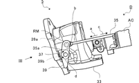
- FIG. 3 is a view on arrow III in FIG.
- a valve a waste gate valve
- the valve 27 is a valve body whose outer diameter is larger than the inner diameter of the outlet end 41a.
- the mounting plate 43 has one end connected to the shaft 37 and the other end connected to the valve 27. Details of the connection structure between the valve 27 and the mounting plate 43 will be described later.
- the valve 27 and the mounting plate 43 rotate integrally with the shaft 37.
- the valve 27 opens and closes the outlet end 41 a of the bypass flow passage 41 by rotating integrally with the shaft 37.
- the valve 27 closes the outlet end 41a of the bypass passage 41 when it comes into contact with a seat surface 41b (see FIG. 1) formed around the outlet end 41a of the bypass passage 41.
- the valve 27 opens the outlet end 41a of the bypass passage 41 when being separated from the seat surface 41b.
- a shaft hole 5b is formed in the turbine housing 5.
- the shaft hole 5b is a through hole extending in the axial direction of the shaft 37 (hereinafter, also simply referred to as the axial direction).
- the shaft hole 5b communicates the outside of the turbine housing 5 with the internal space S1 of the turbine housing 5.
- a part of the shaft 37 and the bearing member 45 are arranged in the shaft hole 5b.
- the bearing member 45 has a cylindrical shape.
- the bearing member 45 has a bearing hole 45a on the inner peripheral surface side.
- the shaft 37 is inserted into the bearing hole 45a.
- the bearing member 45 has one end disposed in the shaft hole 5 b and the other end disposed outside the turbine housing 5.
- the bearing member 45 rotatably supports the shaft 37. The details of the bearing structure that supports the shaft 37 will be described later.
- FIG. 4 is a perspective view of the mounting plate 43.
- FIG. 5 is a side view of the mounting plate 43.
- FIG. 6 is a top view of the mounting plate 43.
- the mounting plate 43 includes a main body 43a and a cylindrical portion 43b.
- the main body 43a has an annular shape.
- a cylindrical portion 43b is connected to an outer peripheral portion of the main body portion 43a.
- the cylindrical portion 43b has a cylindrical shape.
- the cylindrical portion 43b has an insertion hole 43c formed on the inner peripheral surface side. The shaft 37 is inserted into the insertion hole 43c.
- An exposed hole 43d is formed in the cylindrical portion 43b.
- the exposed hole 43d is a through hole that passes through the cylindrical portion 43b in the radial direction.
- the cylindrical portion 43b exposes a part of the shaft 37 from the exposure hole 43d.
- the shaft 37 is, for example, welded to the cylindrical portion 43b via the exposed hole 43d.
- the shaft 37 is attached to the attachment plate 43 by welding the shaft 37 to the cylindrical portion 43b.
- a main body hole 43e is formed in the main body 43a on the inner peripheral surface side.
- the main body hole 43e is a through hole that penetrates the main body 43a in a direction orthogonal to the central axis of the insertion hole 43c. A part of the valve 27 is inserted into the main body hole 43e.
- FIG. 7 is an explanatory diagram for explaining a connection structure between the valve 27 and the mounting plate 43.
- the valve 27 includes a main body 27a and a protrusion 27b.
- the main body 27a has a contact surface 27c.
- the contact surface 27c is configured to be able to contact a sheet surface 41b (see FIG. 1) formed around the outlet end 41a (see FIG. 1).
- the protrusion 27b is formed on the side opposite to the side on which the contact surface 27c of the main body 27a is formed.
- the protrusion 27b extends in a direction orthogonal to the surface direction of the contact surface 27c.
- the protrusion 27b may be formed integrally with the main body 27a, or may be formed as a separate member.
- the main body hole 43e of the mounting plate 43 is inserted into the protrusion 27b.
- a washer 47 is inserted into the protrusion 27b.
- the mounting plate 43 is sandwiched between the main body 27 a of the valve 27 and the washer 47.
- the tip of the protruding portion 27b protruding from the washer 47 is deformed under pressure.
- the bulb 27 is attached to the attachment plate 43 by pressurizing and deforming the tip of the projection 27b.
- FIG. 8 is an explanatory diagram for explaining the configuration of the bearing structure 100 of the present embodiment.
- the bearing structure 100 includes the turbine housing 5, a rotating member RM (the link plate 39 and the shaft 37), and a bearing member 45.
- the shaft hole 5b of the turbine housing 5 accommodates a part of the shaft 37 and the bearing member 45.
- the shaft hole 5b has a circular cross section perpendicular to the axial direction, and has a constant inner diameter.
- the portion below the turbine housing 5 represents the inside of the turbine housing 5 (internal space S1).
- the portion above the turbine housing 5 indicates the outside (external space S2) of the turbine housing 5.
- the upper part in FIG. 8 is the upper part in the vertical direction when the supercharger T is installed, and the lower part in FIG. 8 is the lower part in the vertical direction when the supercharger T is installed.
- the shaft 37 includes a small diameter portion (shaft portion) 37a, a tapered portion (extended portion) 37b, a large diameter portion 37c, and a flange portion 37d.
- the small diameter portion 37a has a columnar shape. One end of the small diameter portion 37a is connected to the link plate 39, and the other end is connected to the tapered portion 37b.
- the small diameter portion 37a has a constant outer diameter. The outer diameter of the small diameter portion 37a is smaller than the inner diameter of the bearing hole 45a of the bearing member 45.
- the tapered portion 37b has a truncated cone shape. One end of the tapered portion 37b is continuous with the small diameter portion 37a, and the other end is continuous with the large diameter portion 37c.
- the tapered portion 37b has an outer diameter that gradually increases from the small diameter portion 37a toward the large diameter portion 37c.
- the smallest outer diameter of the tapered portion 37b is approximately equal to the outer diameter of the small diameter portion 37a. That is, the smallest outer diameter of the tapered portion 37b is smaller than the inner diameter of the bearing hole 45a of the bearing member 45.
- the largest outer diameter of the tapered portion 37b is larger than the inner diameter of the bearing hole 45a of the bearing member 45.
- the outer peripheral surface of the tapered portion 37b has a straight section including the central axis of the shaft 37.
- the present invention is not limited thereto, and the outer peripheral surface of the tapered portion 37b may have a curved section, an arc-shaped section, a stepped section, or a corrugated section including the central axis of the shaft 37.
- the large diameter portion 37c has a cylindrical shape. One end of the large diameter portion 37c is continuous with the tapered portion 37b, and the other end is continuous with the flange portion 37d.
- the large diameter portion 37c has a constant outer diameter.
- the outer diameter of the large diameter portion 37c is substantially equal to the largest outer diameter of the tapered portion 37b.
- the outer diameter of the large diameter portion 37c is larger than the outer diameter of the small diameter portion 37a.
- the outer diameter of the large diameter portion 37c is smaller than the inner diameter of the shaft hole 5b of the turbine housing 5.
- the flange portion 37d has a cylindrical shape.
- the flange portion 37d is continuous with the large diameter portion 37c.
- the flange portion 37d is arranged in the internal space S1 of the turbine housing 5.
- the flange portion 37d has a constant outer diameter.
- the outer diameter of the flange portion 37d is larger than the outer diameter of the large diameter portion 37c.
- the outer diameter of the flange portion 37d is larger than the inner diameter of the shaft hole 5b of the turbine housing 5.
- the bearing member 45 includes one main body 45b into which the small diameter portion 37a is inserted.
- the main body 45b has a cylindrical portion 45c, a flange 45d, and a tapered portion 45e.
- the cylindrical portion 45c has a cylindrical shape. One end of the cylindrical portion 45c is continuous with the tapered portion 45e, and the other end is continuous with the flange portion 45d.
- the cylindrical portion 45c has a tapered portion 45e at an end (hereinafter, referred to as a distal end) opposite to the flange 45d.
- the cylindrical portion 45c faces the small-diameter portion 37a in the radial direction of the shaft 37.
- the tapered portion 45e is disposed in the shaft hole 5b.
- the tapered portion 45e has an annular shape.
- the tapered portion 45e faces the tapered portion 37b in the axial direction of the shaft 37. Therefore, the bearing member 45 can receive a radial load (radial load) of the shaft 37 by the cylindrical portion 45c. The bearing member 45 can receive a load (axial load) in the axial direction of the shaft 37 by the tapered portion 45e.
- the tapered portion 45e has an inner diameter that gradually increases in a direction away from the flange portion 45d.
- the smallest inside diameter of the tapered portion 45e is larger than the outside diameter of the small diameter portion 37a.
- the largest inner diameter of the tapered portion 45e is approximately equal to the largest outer diameter of the tapered portion 37b of the shaft 37.
- the tapered portion (opposed surface) 45e is axially opposed to the tapered portion 37b of the shaft 37.
- the inner diameter of the cylindrical portion 45c has a constant inner diameter.
- the inner diameter of the cylindrical portion 45c is approximately equal to the smallest inner diameter of the tapered portion 45e. That is, the inner diameter of the cylindrical portion 45c is larger than the outer diameter of the small diameter portion 37a.
- the outer diameter of the cylindrical portion 45c is approximately equal to the largest outer diameter of the tapered portion 37b of the shaft 37.
- the outer diameter of the cylindrical portion 45c is smaller than the inner diameter of the shaft hole 5b.
- the flange portion 45d is arranged in the external space S2 (outside the shaft hole 5b).
- the flange portion 45d has an annular shape.
- the flange portion 45d is continuous with the cylindrical portion 45c.
- the inner peripheral surface of the flange portion 45d is flush with the inner peripheral surface of the cylindrical portion 45c.
- the inner peripheral surface of the flange portion 45d may have a smaller diameter than the inner peripheral surface of the cylindrical portion 45c, or may have a larger diameter.
- the outer diameter of the flange portion 45d is larger than the outer diameter of the cylindrical portion 45c.
- the outer diameter of the flange portion 45d is larger than the inner diameter of the shaft hole 5b.
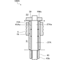
- FIG. 9 is an explanatory diagram for describing the configuration of the bearing structure 100A of the comparative example.
- the bearing structure 100A includes the turbine housing 5, a rotating member RMa (the link plate 39 and the shaft 37A), and a bearing member 45A.
- the bearing structure 100A of the comparative example is different from the bearing structure 100 of the present embodiment in the configuration of the shaft 37A and the bearing member 45A.
- the bearing member 45A is pressed into the shaft hole 5b of the turbine housing 5. One end of the bearing member 45A is disposed in the internal space S1, and the other end is disposed in the external space S2.
- the bearing member 45A has a bearing hole 45Aa.
- the bearing hole 45Aa connects the internal space S1 and the external space S2.
- the bearing hole 45Aa has a constant inner diameter.
- the shaft 37A has a small diameter portion 37Aa.
- the small diameter portion 37Aa is inserted into the bearing hole 45Aa.
- the small diameter portion 37Aa has a constant outer diameter.
- the outer diameter of the small diameter portion 37Aa is smaller than the inner diameter of the bearing hole 45Aa. That is, a gap is formed between the inner peripheral surface of the bearing member 45A and the outer peripheral surface of the small diameter portion 37Aa of the shaft 37A.
- the rotating member RM of the present embodiment is provided with an extending portion extending radially outward of the shaft 37.
- the bearing member 45 of this embodiment is provided with a facing surface that faces the extending portion in the axial direction.
- the rotating member RM of the present embodiment has a tapered portion (extended portion) 37b extending radially outward of the shaft 37.
- the bearing member 45 of the present embodiment has a tapered portion (opposed surface) 45e that faces the tapered portion 37b in the axial direction.
- the rotating member RM of the present embodiment has the lower surface (extending portion) 39c of the link plate 39 extending radially outward of the shaft 37.
- the lower surface 39c is a lower flat surface of the link plate 39 in FIG.
- the bearing member 45 of the present embodiment has an upper surface (opposing surface) 45da of a flange portion 45d axially facing the lower surface 39c of the link plate 39.
- the upper surface 45da is the upper flat surface in FIG. 8 of the flange portion 45d.
- the rotating member RM of the present embodiment extends radially outward from the small diameter portion 37a and has a plurality of extending portions (tapered portions 37b and the lower surface 39c) provided apart from each other in the axial direction. .
- the tapered portion 37b and the lower surface 39c are provided in directions facing each other in the axial direction of the small diameter portion 37a.
- an opposing surface (tapered portion 45e and upper surface 45da) axially opposing any one of the plurality of extending portions (tapered portion 37b and lower surface 39c) is provided in the main body portion 45b.
- the bearing member 45 has a main body 45b located between the pair of extending portions (the tapered portion 37b and the lower surface 39c).
- the main body 45b has a pair of opposing surfaces (tapered portion 45e and upper surface 45da) opposed to a pair of extended portions (tapered portion 37b and lower surface 39c).
- the exhaust gas presses the flange 37d of the shaft 37 in a direction approaching the turbine housing 5.
- the flange portion 37 d approaches the inner peripheral surface of the turbine housing 5. Since the flange portion 37d is close to the inner peripheral surface of the turbine housing 5, the gap between the flange portion 37d and the turbine housing 5 is narrowed. Therefore, it becomes difficult for the exhaust gas to flow into the shaft hole 5b of the turbine housing 5 from the internal space S1.
- the exhaust gas flowing into the shaft hole 5b passes through a gap between the shaft hole 5b and the large diameter portion 37c.
- the exhaust gas that has passed through the gap between the shaft hole 5b and the large-diameter portion 37c passes through the gap between the tapered portion 45e of the bearing member 45 and the tapered portion 37b of the shaft 37.
- the exhaust gas that has passed through the gap between the tapered portion 45e and the tapered portion 37b passes through the gap between the cylindrical portion 45c and the small diameter portion 37a.
- the exhaust gas that has passed through the gap between the cylindrical portion 45c and the small diameter portion 37a passes through the gap between the upper surface 45da of the flange 45d and the lower surface 39c of the link plate 39.
- the exhaust gas that has passed through the gap between the upper surface 45da of the flange portion 45d and the lower surface 39c of the link plate 39 finally flows into the external space S2.
- the exhaust gas passes through the gap between the tapered portion (extended portion) 37b and the tapered portion (opposed surface) 45e.
- the exhaust gas passes through a gap between the lower surface (extending portion) 39c of the link plate 39 and the upper surface (opposing surface) 45da of the flange portion 45d.
- the bearing structure 100 of the present embodiment can have a longer flow path length for exhaust gas flow than the bearing structure 100A of the comparative example.
- exhaust is more exhausted than a structure that does not have the extending portion extending radially outward of the shaft 37 and a facing surface that faces the extending portion in the axial direction.
- the gas flow path length can be increased.
- the flow direction of the exhaust gas changes when the exhaust gas flows from the gap between the flange portion 37d and the turbine housing 5 into the gap between the shaft hole 5b and the large-diameter portion 37c. .
- the flow direction changes.
- the flow direction changes.
- the direction of flow of the exhaust gas changes when flowing into the gap between the upper surface 45da and the lower surface 39c from the gap between the cylindrical portion 45c and the small diameter portion 37a.
- the bearing structure 100 of the present embodiment can increase the pressure loss of the exhaust gas by changing the direction of the flow of the exhaust gas flowing in the shaft hole 5b. Therefore, the bearing structure 100 of the present embodiment can increase the pressure loss of the exhaust gas as compared with the bearing structure 100A of the comparative example (that is, a structure that does not change the direction of the exhaust gas flow).
- the bearing structure 100 of the present embodiment can suppress (reduce) the amount of exhaust gas leaking from the internal space S1 to the external space S2 as compared with the bearing structure 100A of the comparative example.
- the bearing member 45A of the comparative example is press-fitted into the shaft hole 5b of the turbine housing 5, whereas the bearing member 45 of the present embodiment is not press-fitted into the shaft hole 5b. That is, the outer peripheral surface of the bearing member 45 of the present embodiment is separated from the turbine housing 5 (the inner peripheral surface of the shaft hole 5b). Therefore, a gap is formed between the bearing member 45 of the present embodiment and the turbine housing 5.
- the bearing member 45 of the present embodiment is rotatably provided in the shaft hole 5 b of the turbine housing 5.
- the bearing member 45 of the present embodiment is provided movably with respect to the shaft hole 5b of the turbine housing 5 in the central axis direction of the shaft hole 5b (the axial direction of the shaft 37). Thereby, the bearing member 45 of the present embodiment floats in the shaft hole 5b of the turbine housing 5.
- the bearing member 45 of the present embodiment is configured to float in the shaft hole 5b.
- the relative speed and the load (contact pressure) when the shaft 37 and the bearing member 45 collide with each other are reduced.
- the amount of wear of the shaft 37 and the bearing member 45 decreases because the relative speed and the load (contact pressure) at the time of collision with each other decrease.
- the relative speed and load (contact pressure) of the shaft 37 and the bearing member 45 when they collide with each other are reduced, so that noise is reduced.
- the distance between the inner peripheral surface of the shaft hole 5b and the outer peripheral surface of the bearing member 45 is determined by the distance between the inner peripheral surface of the bearing member 45 and the outer periphery of the shaft 37 (small diameter portion 37a). Shorter than the distance between the plane.
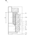
- FIG. 10 is an explanatory diagram for explaining a flow path of exhaust gas.
- FIG. 10 is an extraction diagram of a broken line portion shown in FIG.
- the flow path cross-sectional area Sa between the inner peripheral surface of the shaft hole 5b and the outer peripheral surface of the bearing member 45 is determined by the inner peripheral surface of the bearing member 45 and the outer peripheral surface of the shaft 37 (small diameter portion 37a). Is smaller than the flow path cross-sectional area Sb. That is, the relational expression of the flow path cross-sectional areas Sa and Sb is Sa ⁇ Sb.
- the exhaust gas flows between the inner peripheral surface of the shaft hole 5b and the outer peripheral surface of the bearing member 45 as shown by a two-dot chain line in FIG. Flow through the gap (flow path). Exhaust gas easily flows through a gap (flow path) between the inner peripheral surface of the bearing member 45 and the outer peripheral surface of the shaft 37 (small-diameter portion 37a), as indicated by a chain line in FIG.
- the difficulty of flowing exhaust gas varies according to the length of the flow path (flow path length). Exhaust gas becomes more difficult to flow as the flow path length increases.
- the axial flow path length of the gap (flow path) between the inner peripheral surface of the shaft hole 5b and the outer peripheral surface of the bearing member 45 is defined as L1.
- the axial flow path length of the gap (flow path) between the inner peripheral surface of the bearing member 45 and the outer peripheral surface of the shaft 37 (small diameter portion 37a) is defined as L2.
- the value (Sa / L1) obtained by dividing the flow path cross-sectional area Sa by the flow path length L1 is smaller than the value (Sb / L2) obtained by dividing the flow path cross-sectional area Sb by the flow path length L2. That is, the relational expression between the flow path cross-sectional areas Sa and Sb and the flow path lengths L1 and L2 is (Sa / L1) ⁇ (Sb / L2).
- FIG. 11 is an explanatory diagram for explaining the axial length of the bearing member 45 and the turbine housing 5.
- FIG. 11 is an extraction diagram of a broken line portion shown in FIG.
- a distance from the upper end 5UE of the turbine housing 5 to the lower end 45LE of the inner peripheral surface of the bearing member 45 in the axial direction of the shaft 37 is represented by L3.
- the distance from the upper end 5UE of the turbine housing 5 to the lower end 5LE of the turbine housing 5 in the axial direction of the shaft 37 (that is, the thickness of the turbine housing 5) is L4.
- the distance L3 has a length equal to or more than half of the distance L4. Since the distance L3 is at least half the length of the distance L4, the bearing member 45 can stably support the shaft 37, and eventually the valve 27 (see FIG. 3).
- FIG. 12 is a view showing a state of the bearing member 45 when the pressure of the exhaust gas in the internal space S1 is lower than a predetermined pressure.
- the bearing member 45 of the present embodiment is not pressed into the shaft hole 5b. Therefore, when the pressure of the exhaust gas in the internal space S1 is lower than the predetermined pressure, the bearing member 45 of the present embodiment moves vertically downward (downward in FIG. 12) due to gravity.
- the tapered portion (extended portion) 37b of the shaft 37 approaches the tapered portion (opposed surface) 45e of the bearing member 45.
- the tapered portion (extended portion) 37b of the shaft 37 comes into contact with the tapered portion (opposed surface) 45e of the bearing member 45.
- the gap between the bearing member 45 and the shaft 37 is sealed (closed) by the contact between the tapered portion (opposing surface) 45e and the tapered portion (extended portion) 37b.
- the bearing structure 100 of the present embodiment when the pressure of the exhaust gas in the internal space S1 is lower than the predetermined pressure, the gap between the bearing member 45 and the shaft 37 (the bearing member 45 and the turbine housing 5) is reduced. Can be sealed. Therefore, the bearing structure 100 of the present embodiment can suppress (reduce) the amount of exhaust gas leaking from the internal space S1 to the external space S2.
- FIG. 13 is a view showing a state of the bearing member 45 when the pressure of the exhaust gas in the internal space S1 is equal to or higher than a predetermined pressure.
- the bearing member 45 of the present embodiment is pressed by the exhaust gas and moves vertically upward (upward in FIG. 13).
- the upper surface (facing surface) 45da of the flange portion 45d contacts the lower surface (extending portion) 39c of the link plate 39. That is, the gap between the bearing member 45 and the link plate 39 is sealed by the upper surface (opposed surface) 45da and the lower surface (extended portion) 39c.
- the bearing structure 100 of the present embodiment can seal the gap between the bearing member 45 and the link plate 39 when the pressure of the exhaust gas in the internal space S1 is equal to or higher than the predetermined pressure. Therefore, the bearing structure 100 of the present embodiment can suppress (reduce) the amount of exhaust gas leaking from the internal space S1 to the external space S2.
- FIG. 14 is an explanatory diagram for describing the configuration of the bearing structure 200 according to the first modification. Components that are substantially the same as the supercharger T of the above embodiment are given the same reference numerals, and description thereof is omitted.
- the bearing structure 200 of the first modified example includes a rotating member RMb instead of the rotating member RM of the above embodiment.
- the rotation member RMb includes a link plate 39 and a shaft 137.
- the bearing structure 200 of the first modified example includes a bearing member 145 instead of the bearing member 45 of the above embodiment.
- the shaft 137 of the first modified example has a first small diameter portion (shaft portion) 137a, a first tapered portion (extended portion) 137b, a large diameter portion 137c, and a second tapered portion 137d. And a second small diameter portion (shaft portion) 137e.
- the first small diameter portion 137a has a columnar shape. One end of the first small diameter portion 137a is connected to the link plate 39, and the other end is continuous with the first tapered portion 137b.
- the first small diameter portion 137a has a constant outer diameter. The outer diameter of the first small diameter portion 137a is smaller than the inner diameter of the bearing hole 45a of the bearing member 145.
- the first tapered portion (first extending portion) 137b has a truncated cone shape. One end of the first tapered portion 137b is continuous with the first small diameter portion 137a, and the other end is continuous with the large diameter portion 137c.
- the first tapered portion 137b has an outer diameter that gradually increases from the first small diameter portion 137a to the large diameter portion 137c.
- the smallest outer diameter of the first tapered portion 137b is substantially equal to the outer diameter of the first small diameter portion 137a. That is, the smallest outer diameter of the first tapered portion 137b is smaller than the inner diameter of the bearing hole 45a of the bearing member 145.
- the largest outer diameter of the first tapered portion 137b is larger than the inner diameter of the bearing hole 45a of the bearing member 145.
- the large-diameter portion 137c has a cylindrical shape. One end of the large diameter portion 137c is continuous with the first tapered portion 137b, and the other end is continuous with the second tapered portion 137d.
- the large diameter portion 137c has a constant outer diameter.
- the outer diameter of the large diameter portion 137c is substantially equal to the largest outer diameter of the first tapered portion 137b.
- the outer diameter of the large diameter part 137c is larger than the outer diameter of the first small diameter part 137a.
- the outer diameter of the large diameter portion 137c is smaller than the inner diameter of the shaft hole 5b of the turbine housing 5.
- the second tapered portion (second extending portion) 137d has a truncated cone shape. One end of the second tapered portion 137d is continuous with the large diameter portion 137c, and the other end is continuous with the second small diameter portion 137e.
- the second tapered portion 137d has an outer diameter that gradually decreases from the large diameter portion 137c to the second small diameter portion 137e.
- the smallest outer diameter of the second tapered portion 137d is smaller than the inner diameter of the bearing hole 45a of the bearing member 145.
- the largest outer diameter of the second tapered portion 137d is larger than the inner diameter of the bearing hole 45a of the bearing member 145.
- the large diameter portion 137c has the extending portions (the first tapered portion 137b and the second tapered portion 137d) on one side and the other side in the axial direction of the shaft 137, respectively. Provided.
- the second small diameter portion 137e has a columnar shape. One end of the second small diameter portion 137e is continuous with the second tapered portion 137d, and the other end is disposed in the internal space S1 of the turbine housing 5.
- the second small diameter portion 137e has a constant outer diameter.
- the outer diameter of the second small diameter portion 137e is smaller than the inner diameter of the bearing hole 45a of the bearing member 145.
- the outer diameter of the second small diameter part 137e is substantially equal to the outer diameter of the first small diameter part 137a.
- the bearing member 145 of the first modification includes a first main body 145a and a second main body 145b.
- the first main body 145a is inserted through the first small diameter portion 137a.
- the first main body 145a includes the cylindrical portion 45c of the above embodiment, a flange 45d, and a tapered portion 45e.
- the second main body 145b is inserted through the second small diameter portion 137e.
- the second main body 145b includes the cylindrical portion 45c, the flange 45d, and the tapered portion 45e of the above embodiment.
- the first main body 145a is disposed on the first tapered portion 137b side (upper side in FIG. 14) with respect to the large diameter portion 137c.
- the second main body 145b is disposed on the second tapered portion 137d side (the lower side in FIG. 14) with respect to the large diameter portion 137c. That is, the bearing member 145 of the first modified example includes a plurality of main bodies (first main body 145a and second main body 145b) provided on one side and the other side in the axial direction of the large diameter section 137c. .
- the first main body 145a and the second main body 145b have a pair of tapered portions (first opposing surfaces) 45e and tapered portions (second opposing surfaces) 45e provided in directions facing each other in the axial direction of the shaft 137. Including.
- the tapered portion 45e of the first main body 145a is axially opposed to the tapered portion 45e of the second main body 145b via the large-diameter portion 137c.
- the bearing member 145 (the first main body 145a and the second main body 145b) floats in the shaft hole 5b.
- the inner diameter of the second main body 145b is smaller than the outer diameter of the cylindrical portion 43b of the mounting plate 43.
- the cylindrical portion 43b of the mounting plate 43 can support the second main body 145b.
- the rotation member RMb of the first modification includes a plurality of extending portions extending radially outward of the shaft 137.
- the bearing member 145 of the first modified example has a plurality of opposing surfaces that oppose the plurality of extending portions in the axial direction.
- the rotating member RMb of the first modified example has a first tapered portion (first extending portion) 137b extending radially outward of the shaft 137 and a second tapered portion (second extending portion). 137d).
- the bearing member 145 of the first modified example has a tapered portion (first facing surface) 45e of a first main body portion 145a axially facing the first tapered portion 137b.
- the bearing member 145 of the first modified example has a tapered portion (second facing surface) 45e of a second main body portion 145b axially facing the second tapered portion 137d.
- the exhaust gas presses the flange 45d of the second main body 145b in a direction approaching the turbine housing 5.
- the flange portion 45 d approaches the inner peripheral surface of the turbine housing 5. Since the flange 45d is close to the inner peripheral surface of the turbine housing 5, the gap between the flange 45d and the turbine housing 5 is narrowed. Therefore, it becomes difficult for the exhaust gas to flow into the shaft hole 5b from the gap between the flange portion 45d and the turbine housing 5.
- the exhaust gas that has passed through the gap between the second tapered portion 137d and the tapered portion 45e of the second main body 145b passes through the gap between the shaft hole 5b and the large diameter portion 137c.
- Exhaust gas that has passed through the gap between the shaft hole 5b and the large diameter portion 137c passes through the gap between the first tapered portion 137b and the tapered portion 45e of the first main body 145a.
- the exhaust gas that has passed through the gap between the first tapered portion 137b and the tapered portion 45e of the first main body 145a passes through the gap between the first small diameter portion 137a and the first main body 145a.
- the exhaust gas that has passed through the gap between the first small diameter portion 137a and the first main body 145a passes through the gap between the upper surface 45da of the flange 45d of the first main body 145a and the lower surface 39c of the link plate 39.
- the exhaust gas that has passed through the gap between the upper surface 45da of the flange 45d and the lower surface 39c of the link plate 39 flows out to the external space S2.
- the exhaust gas flows between the first tapered portion (first extending portion) 137b and the tapered portion (first facing surface) 45e of the first main body portion 145a. Pass through the gap.
- the exhaust gas passes through a gap between the second tapered portion (second extending portion) 137d and the tapered portion (second facing surface) 45e of the second main body 145b.
- the bearing structure 200 of the first modified example can have a longer flow path length for exhaust gas flow than the bearing structure 100A of the comparative example. That is, the bearing structure 200 includes an extending portion (first extending portion, second extending portion) extending radially outward of the shaft 137, and a facing surface axially facing the extending portion.
- the flow path length of the exhaust gas can be made longer as compared with a structure having no (first facing surface, second facing surface).
- the direction of the flow of exhaust gas changes when flowing through the gap between the first tapered portion 137b and the tapered portion 45e of the first main body 145a. Further, the direction of the flow of the exhaust gas changes when flowing through the gap between the second tapered portion 137d and the tapered portion 45e of the second main body 145b. The direction of the flow of the exhaust gas changes when flowing through the gap between the upper surface 45da of the flange portion 45d of the first main body 145a and the lower surface 39c of the link plate 39.
- the bearing structure 200 of the first modification can increase the pressure loss of the exhaust gas as compared with the bearing structure 100A of the comparative example (that is, a structure that does not change the direction of the exhaust gas flow).
- the bearing structure 200 of the first modification can suppress (reduce) the amount of exhaust gas leaking from the internal space S1 to the external space S2 as compared with the bearing structure 100A of the comparative example.
- the flow path cross-sectional areas Sa and Sb and the flow path lengths L1 and L2 have the above-described relationship.
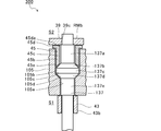
- FIG. 15 is an explanatory diagram for describing a configuration of a bearing structure 300 according to a second modification. Constituent elements that are substantially the same as the supercharger T of the above-described embodiment and the first modified example are denoted by the same reference numerals, and description thereof is omitted.
- the bearing structure 300 of the second modified example includes a rotating member RMb of the first modified example instead of the rotating member RM of the above embodiment.
- the bearing structure 300 of the second modification includes a turbine housing 105 instead of the turbine housing 5 of the above embodiment.
- the turbine housing 105 of the second modification has a shaft hole 105b.
- the shaft hole 105b has a large-diameter hole 105c, a reduced-diameter hole 105d, and a small-diameter hole 105e.
- the large diameter hole 105c has a circular cross section perpendicular to the axial direction. One end of the large diameter hole 105c is open to the external space S2, and the other end is continuous with the reduced diameter hole 105d.
- the large diameter hole 105c has a constant inner diameter.
- the inner diameter of the large-diameter hole portion 105c is larger than the outer diameter of the cylindrical portion 45c of the bearing member 45.
- the inner diameter of the large diameter hole portion 105c is larger than the outer diameter of the large diameter portion 137c of the shaft 137.
- the reduced diameter hole portion 105d has a circular cross section orthogonal to the axial direction. One end of the reduced diameter hole portion 105d is continuous with the large diameter hole portion 105c, and the other end is continuous with the small diameter hole portion 105e.
- the reduced diameter hole portion 105d has a tapered shape in which the inner diameter gradually decreases from the large diameter hole portion 105c toward the small diameter hole portion 105e.
- the largest inner diameter of the reduced diameter holes 105d is larger than the largest outer diameter of the second tapered portion 137d.
- the smallest inner diameter of the reduced diameter hole portion 105d is smaller than the largest outer diameter of the second tapered portion 137d.
- the small diameter hole 105e has a circular cross section perpendicular to the axial direction. One end of the small diameter hole 105e is continuous with the reduced diameter hole 105d, and the other end is open to the internal space S1.
- the small diameter hole 105e has a constant inner diameter.
- the inner diameter of the small diameter portion 105e is larger than the outer diameter of the second small diameter portion 137e.
- the inner diameter of the small-diameter hole portion 105e is smaller than the largest outer diameter of the second tapered portion 137d.
- Rotating member RMb of the second modified example includes an extending portion extending radially outward of shaft 137.
- the bearing member 45 of the second modified example has a facing surface that faces the extending portion in the axial direction.
- the rotating member RMb of the second modified example has a first tapered portion (extended portion) 137b extending radially outward of the shaft 137.
- the bearing member 45 of the second modified example has a tapered portion (opposed surface) 45e that faces the first tapered portion 137b in the axial direction.
- the rotating member RMb of the second modification has a lower surface (extending portion) 39c of a link plate 39 extending radially outward of the shaft 137.
- the bearing member 45 of the second modified example has an upper surface (opposing surface) 45da of a flange portion 45d axially facing the lower surface 39c of the link plate 39.
- the rotation member RMb of the second modification has a second tapered portion 137d extending radially outward of the shaft 137.
- the turbine housing 105 of the second modified example has a reduced diameter hole portion 105d that faces the second tapered portion 137d in the axial direction.
- the exhaust gas passes through the gap between the first tapered portion (extended portion) 137b and the tapered portion (opposed surface) 45e.
- the exhaust gas passes through a gap between the second tapered portion 137d and the reduced diameter hole portion 105d.
- the exhaust gas passes through a gap between the lower surface (extending portion) 39c of the link plate 39 and the upper surface (opposing surface) 45da of the flange portion 45d.
- the bearing structure 300 of the second modified example can make the flow path length of the exhaust gas flow longer than the bearing structure 100A of the comparative example.
- the bearing structure 300 has a flow path of the exhaust gas as compared with a structure that does not have the extending portion extending outward in the radial direction of the shaft 137 and the facing surface that faces the extending portion in the axial direction. The length can be lengthened.
- the direction of the flow of the exhaust gas changes when flowing through the gap between the first tapered portion 137b and the tapered portion 45e of the bearing member 45.
- the direction of the flow of the exhaust gas changes when flowing through the gap between the second tapered portion 137d and the reduced diameter hole portion 105d.
- the flow direction of the exhaust gas changes when flowing through the gap between the upper surface 45da of the flange portion 45d and the lower surface 39c of the link plate 39.
- the bearing structure 300 of the second modification can increase the pressure loss of the exhaust gas as compared with the bearing structure 100A of the comparative example (that is, a structure that does not change the direction of the flow of the exhaust gas).
- the bearing structure 300 of the second modification can suppress (reduce) the amount of exhaust gas leaking from the internal space S1 to the external space S2, as compared with the bearing structure 100A of the comparative example.
- the flow path cross-sectional areas Sa and Sb and the flow path lengths L1 and L2 have the above-described relationship.
- FIG. 16 is an explanatory diagram for describing a configuration of a bearing structure 400 according to the third modification. Constituent elements that are substantially the same as the supercharger T of the above-described embodiment and the first modified example are denoted by the same reference numerals, and description thereof is omitted.
- the bearing structure 400 of the third modified example includes the rotating member RMb of the first modified example, instead of the rotating member RM of the above embodiment.
- the bearing structure 400 of the third modification includes a bearing member 245 instead of the bearing member 45 of the above embodiment.
- the bearing member 245 includes main bodies 245a, 245b, and 245c formed of a plurality of members divided in the axial direction.
- the bearing structure 400 of the third modified example includes a positioning bearing member 345 press-fitted into the shaft hole 5b of the turbine housing 5.
- the bearing structure 400 of the third modified example includes a bearing member 245 and a positioning bearing member 345.
- the bearing member 245 is not pressed into the shaft hole 5b of the turbine housing 5.
- the bearing member 245 is rotatable with respect to the shaft hole 5b of the turbine housing 5.
- the bearing member 245 is movable with respect to the shaft hole 5b of the turbine housing 5 in the central axis direction of the shaft hole 5b (the axial direction of the shaft 137).
- the bearing member 245 includes a plurality of members (main body portions 245a, 245b, 245c) through which the first small diameter portion 137a is inserted.
- the bearing member 245 has a shape obtained by dividing the bearing member 45 of the above embodiment in the axial direction.
- the main body part 245a includes a part of the flange part 45d and the cylindrical part 45c of the bearing member 45 of the above embodiment.
- the main body 245b includes a part of the cylindrical portion 45c of the bearing member 45 of the above embodiment.
- the main body 245c includes a part of the cylindrical portion 45c of the bearing member 45 of the above embodiment and a tapered portion 45e.
- the exhaust gas flows between the main body portion 245a and the main body portion 245b and between the main body portion 245b and the main body portion 245c. Can be distributed. This complicates the flow path of the exhaust gas.
- the number of times of changing the direction of the flow of the exhaust gas flowing in the shaft hole 5b increases.
- the pressure loss of the exhaust gas can be increased by increasing the number of times of changing the direction of the flow of the exhaust gas.
- the positioning bearing member 345 has the main body 45b, the cylindrical portion 45c, the flange 45d, and the tapered portion 45e of the bearing member 45 of the above embodiment. However, the positioning bearing member 345 is press-fitted into the shaft hole 5b of the turbine housing 5. That is, the outer peripheral surface of the positioning bearing member 345 is in contact with the inner peripheral surface of the shaft hole 5b.
- the positioning bearing member 345 cannot rotate with respect to the shaft hole 5b of the turbine housing 5.
- the positioning bearing member 345 cannot move with respect to the shaft hole 5b of the turbine housing 5 in the central axis direction of the shaft hole 5b (the axial direction of the shaft 137). That is, the axial movement of the shaft 137 of the positioning bearing member 345 (the main body 45b) is restricted.
- the positioning bearing member 345 can support the second tapered portion 137d of the shaft 137 via the tapered portion 45e. Therefore, the bearing structure 400 of the third modified example can easily position the shaft 137 by adjusting the press-fit position of the positioning bearing member 345. By positioning the shaft 137, the assemblability of the bearing structure 400 can be improved. Specifically, by positioning the shaft 137, the operator can easily attach (for example, weld) the attachment plate 43 to the shaft 137. By positioning the shaft 137, the operator can easily attach (for example, weld) the link plate 39 to the shaft 137.
- the rotating member RMb of the third modified example includes an extending portion extending radially outward of the shaft 137.
- the bearing member 245 of the third modified example has an opposing surface that opposes the extending portion in the axial direction.
- the rotating member RMb of the third modified example has a first tapered portion (extended portion) 137b extending radially outward of the shaft 137.
- the bearing member 245 of the third modified example has a tapered portion (opposed surface) 45e that faces the first tapered portion 137b in the axial direction.
- the rotating member RMb of the third modification has a lower surface (extending portion) 39c of a link plate 39 extending radially outward of the shaft 137.
- the bearing member 245 of the third modified example has an upper surface (opposed surface) 45da of a flange portion 45d axially facing the lower surface 39c of the link plate 39.
- the rotating member RMb of the third modified example has a second tapered portion 137d extending radially outward of the shaft 137.
- the positioning bearing member 345 of the third modified example has a tapered portion 45e that faces the second tapered portion 137d in the axial direction.
- the exhaust gas passes through the gap between the first tapered portion (extended portion) 137b and the tapered portion (opposing surface) 45e.
- the exhaust gas passes through a gap between the second tapered portion 137d and the tapered portion 45e.
- the exhaust gas passes through a gap between the lower surface (extending portion) 39c of the link plate 39 and the upper surface (opposing surface) 45da of the flange portion 45d.
- the bearing structure 400 of the third modified example can make the flow path length of the exhaust gas flow longer than the bearing structure 100A of the comparative example.
- the bearing structure 400 has a flow path of exhaust gas as compared with a structure that does not have the extending portion that extends outward in the radial direction of the shaft 137 and a structure that does not have the facing surface that faces the extending portion in the axial direction. The length can be lengthened.
- the direction of the flow of the exhaust gas changes when flowing through the gap between the first tapered portion 137b and the main body 245c.
- the direction of the flow of the exhaust gas changes when flowing through the gap between the second tapered portion 137d and the flange portion 45d of the positioning bearing member 345.
- the direction of the flow of the exhaust gas changes when flowing through the gap between the upper surface 45da of the flange portion 45d and the lower surface 39c of the link plate 39.
- the direction of flow of the exhaust gas changes when flowing through the gap between the main body 245a and the main body 245b.
- the exhaust gas changes its flow direction when flowing through the gap between the main body 245b and the main body 245c.
- the bearing structure 400 of the third modification can increase the pressure loss of the exhaust gas as compared with the bearing structure 100A of the comparative example (that is, a structure that does not change the direction of the exhaust gas flow).
- the bearing structure 400 of the third modified example can suppress (reduce) the amount of exhaust gas leaking from the internal space S1 to the external space S2 as compared with the bearing structure 100A of the comparative example.
- the flow path cross-sectional areas Sa and Sb and the flow path lengths L1 and L2 have the above-described relationship.
- the bearing structures 100, 200, 300, and 400 that operate the valve 27 that opens and closes the outlet end 41a of the bypass flow passage 41 have been described.
- the present invention is not limited to this, and the bearing structures 100, 200, 300, and 400 may be applied to a bearing structure that supports another shaft that passes through the inside and outside of the housing of the turbocharger T.
- the bearing structures 100, 200, 300, and 400 may be applied to the bearing structure of a twin scroll supercharger.
- the bearing structure 100, 200, 300, 400 may operate a valve that opens and closes a communication hole that communicates the two turbine scroll flow paths.
- the bearing structures 100, 200, 300, and 400 may be applied to a bearing structure of a series-type multi-stage supercharger in which a low-pressure stage and a high-pressure stage supercharger are connected in series to an exhaust manifold of an engine.
- the bearing structures 100, 200, 300, and 400 may be applied to a bearing structure of a parallel-type multi-stage supercharger in which a plurality of superchargers are connected in parallel to an exhaust manifold of an engine.
- the bearing structure 100, 200, 300, 400 may operate an adjusting member that adjusts the flow rate of the exhaust gas flowing into the turbine housing of one of the superchargers constituting the multi-stage supercharger.
- the bearing structures 100, 200, 300, and 400 may be applied to a bearing structure of a variable vane mechanism that changes the degree of communication between the turbine scroll flow path and the discharge port.
- the bearing structure 100, 200, 300, 400 may operate a rotating member that rotates the nozzle vane of the variable vane mechanism.
- the bearing members 45, 145, and 245 floating in the shaft hole 5b pivotally support the shafts 37 and 137 provided with the extending portions.
- the present invention is not limited to this, and the bearing members 45, 145, and 245 floating in the shaft hole 5b may support a shaft having no extending portion.
- the bearing members 45, 145, and 245 floating in the shaft hole 5b may support a straight shaft having a constant outer diameter (hereinafter, simply referred to as a straight shaft).
- the shaft when the shaft (straight shaft) is rotationally driven by the drive mechanism, a force may act on the shaft in a direction in which the central axis is inclined.
- the shaft collides with the bearing member.
- the bearing member if the bearing member is pressed into the turbine housing, the shaft and the bearing member may generate wear and noise when they collide with each other.
- the bearing members 45, 145, 245 are rotatably provided in the shaft hole 5b of the turbine housing 5.
- the bearing members 45, 145, 245 are provided movably with respect to the shaft hole 5 b of the turbine housing 5 in the center axis direction of the shaft hole 5 b (the axial direction of the straight shaft).
- the bearing members 45, 145, and 245 are configured to support the straight shaft and float in the shaft hole 5b. Thereby, the relative speed and the load (contact pressure) when the straight shaft and the bearing members 45, 145, 245 collide with each other are reduced. The amount of wear of the straight shaft and the bearing members 45, 145, and 245 decreases because the relative speed and the load (contact pressure) at the time of collision with each other decrease. The straight shaft and the bearing members 45, 145, and 245 reduce the relative speed and load (contact pressure) when they collide with each other, so that noise is reduced.
- the present disclosure can be used for a bearing structure.
- Rotating member 5 Turbine housing b5b: Shaft hole (through hole) 37a: Small diameter portion (shaft portion) 37b: Tapered portion (extended portion) 37c: Large diameter portion 39: Link plate 39c: Lower surface (extended portion) 45: bearing member 45b: body portion 45d: flange portion 45da: upper surface (opposing surface) 45e: tapered portion (opposing surface, first opposing surface, second opposing surface) 100: bearing structure 105: turbine housing 137a: first small diameter Part (shaft part) 137b: First taper part (first extension part) 137d: Second taper part (second extension part) 145: Bearing member 200: Bearing structure 245: Bearing member 45 245a: Body part 245b: Body Part 245c: Body part 300: Bearing structure 345: Positioning bearing member 400: Bearing structure
Landscapes
- Engineering & Computer Science (AREA)
- General Engineering & Computer Science (AREA)
- Mechanical Engineering (AREA)
- Chemical & Material Sciences (AREA)
- Combustion & Propulsion (AREA)
- Supercharger (AREA)
Abstract
軸受構造100は、軸部から径方向外方に向けて延在し、軸部の軸方向に互いに離隔して設けられる複数の延在部(テーパ部37bおよびリンク板39)を有する回転部材RMと、複数の延在部のいずれかと軸方向に対向する対向面(テーパ部45e)が、1または複数の本体部45bに設けられた軸受部材45と、を備える。
Description
本開示は、軸受構造に関する。本出願は2018年10月5日に提出された日本特許出願第2018-190453号に基づく優先権の利益を主張するものであり、その内容は本出願に援用される。
特許文献1には、タービンハウジングの排気ガスシール構造について開示がある。排気ガスシール構造は、タービンハウジングと、軸受部材と、シャフトと、シール部材とを備える。軸受部材は、タービンハウジングに設けられる。軸受部材は、シャフトを回転自在に支持する。軸受部材は、シャフトの軸方向と直交する端面を有する。シャフトは、軸受部材の端面と対向する座面を有する。シール部材は、バネ部材を備える。バネ部材は、軸受部材に対して、軸受部材の端面をシャフトの座面に押し付ける側に付勢する。
タービンハウジング内は、500℃以上となる高温の排気ガスが流通している。そのため、バネ部材は、500℃以上となる高温環境下に配される。バネ部材は、高温環境下に配されると、高温によるへたりが生じる場合がある。その場合、バネ部材は、軸受部材の端面をシャフトの座面に押し付ける付勢力が低減する。バネ部材の付勢力が低減すると、排気ガスがシャフトと軸受部材の隙間を通ってタービンハウジング外に漏出するおそれがある。
本開示は、排気ガスの漏出を抑制することが可能な軸受構造を提供することを目的とする。
上記課題を解決するために、本開示の軸受構造は、軸部、および、軸部から径方向外方に向けて延在し、軸部の軸方向に互いに離隔して設けられる複数の延在部を有する回転部材と、軸部が挿通される1または複数の本体部を有し、複数の延在部のいずれかと軸方向に対向する対向面が、1または複数の本体部に設けられた軸受部材と、軸受部材が設けられる貫通孔が形成されたタービンハウジングと、を備える。
回転部材は、軸方向に互いに対向する向きに設けられる一対の延在部を含んでもよい。
軸受部材は、軸方向に互いに対向する向きに設けられる一対の延在部の間に位置し、一対の延在部それぞれに対向する一対の対向面を有する本体部を含んでもよい。
軸受部材は、軸方向に互いに対向する向きに設けられる一対の対向面を含んでもよい。
回転部材は、軸部よりも径が大きく、軸方向の一方側および他方側にそれぞれ延在部が設けられる大径部を備え、軸受部材は、対向面を有し、大径部よりも軸方向の一方側および他方側のそれぞれに設けられる複数の本体部を含んでもよい。
軸受部材は、軸方向に移動可能に設けられる本体部と、軸方向の移動が規制された本体部とを含んでもよい。
軸受部材は、軸方向に分割された複数の部材で構成される本体部を含んでもよい。
本開示によれば、排気ガスの漏出を抑制することができる。
以下に添付図面を参照しながら、本開示の一実施形態について説明する。実施形態に示す寸法、材料、その他具体的な数値等は、理解を容易とするための例示にすぎず、特に断る場合を除き、本開示を限定するものではない。なお、本明細書および図面において、実質的に同一の機能、構成を有する要素については、同一の符号を付することにより重複説明を省略し、また本開示に直接関係のない要素は図示を省略する。
図1は、過給機Tの概略断面図である。以下では、図1に示す矢印L方向を過給機Tの左側として説明する。図1に示す矢印R方向を過給機Tの右側として説明する。図1に示すように、過給機Tは、過給機本体1を備えて構成される。過給機本体1は、ベアリングハウジング3と、タービンハウジング5と、コンプレッサハウジング7とを含んで構成される。タービンハウジング5は、ベアリングハウジング3の左側に締結機構9によって連結される。コンプレッサハウジング7は、ベアリングハウジング3の右側に締結ボルト11によって連結される。
ベアリングハウジング3の外周面には、突起3aが設けられる。突起3aは、タービンハウジング5側に設けられる。突起3aは、ベアリングハウジング3の径方向に突出する。タービンハウジング5の外周面には、突起5aが設けられる。突起5aは、ベアリングハウジング3側に設けられる。突起5aは、タービンハウジング5の径方向に突出する。ベアリングハウジング3とタービンハウジング5は、締結機構9によってバンド締結される。締結機構9は、例えば、Gカップリングで構成される。締結機構9は、突起3a、5aを挟持する。
ベアリングハウジング3には、回転軸孔3bが形成される。回転軸孔3bは、過給機Tの左右方向に貫通する。回転軸孔3bは、すべり軸受を介して回転軸13を回転自在に軸支する。回転軸13の左端部には、タービンインペラ15が設けられる。タービンインペラ15は、タービンハウジング5に回転自在に収容される。回転軸13の右端部には、コンプレッサインペラ17が設けられる。コンプレッサインペラ17は、コンプレッサハウジング7に回転自在に収容される。
コンプレッサハウジング7には、吸気口19が形成される。吸気口19は、過給機Tの右側に開口する。吸気口19は、不図示のエアクリーナに接続される。ベアリングハウジング3とコンプレッサハウジング7の対向面によって、ディフューザ流路21が形成される。ディフューザ流路21は、空気を昇圧する。ディフューザ流路21は、環状に形成される。ディフューザ流路21は、径方向内側において、コンプレッサインペラ17を介して吸気口19に連通している。
コンプレッサハウジング7には、コンプレッサスクロール流路23が設けられる。コンプレッサスクロール流路23は、環状に形成される。コンプレッサスクロール流路23は、例えば、ディフューザ流路21よりも回転軸13の径方向外側に位置する。コンプレッサスクロール流路23は、不図示のエンジンの吸気口と、ディフューザ流路21とに連通している。コンプレッサインペラ17が回転すると、吸気口19からコンプレッサハウジング7内に空気が吸気される。吸気された空気は、コンプレッサインペラ17の翼間を流通する過程において加圧加速される。加圧加速された空気は、ディフューザ流路21およびコンプレッサスクロール流路23で昇圧される。昇圧された空気は、エンジンの吸気口に導かれる。
タービンハウジング5には、吐出口25が形成される。吐出口25は、過給機Tの左側に開口する。吐出口25は、不図示の排気ガス浄化装置に接続される。タービンハウジング5は、吐出口25側に内部空間S1が形成される。内部空間S1には、後述するバルブ27が配される。タービンハウジング5には、連通路29と、タービンスクロール流路31とが形成される。タービンスクロール流路31は、環状に形成される。タービンスクロール流路31は、例えば、連通路29よりもタービンインペラ15の径方向外側に位置する。タービンスクロール流路31は、ガス流入口33(図2参照)と連通する。ガス流入口33には、不図示のエンジンの排気マニホールドから排出される排気ガスが導かれる。連通路29は、タービンインペラ15を介してタービンスクロール流路31と吐出口25とを連通させる。ガス流入口33からタービンスクロール流路31に導かれた排気ガスは、連通路29、タービンインペラ15、および、内部空間S1を介して吐出口25に導かれる。吐出口25に導かれる排気ガスは、流通過程においてタービンインペラ15を回転させる。
タービンインペラ15の回転力は、回転軸13を介してコンプレッサインペラ17に伝達される。コンプレッサインペラ17が回転すると、上記のとおりに空気が昇圧される。こうして、空気がエンジンの吸気口に導かれる。
図2は、タービンハウジング5の外観図である。図2に示すように、タービンハウジング5の外部には、駆動機構Dが配される。駆動機構Dは、アクチュエータロッド35と、アクチュエータACとを備える。アクチュエータロッド35は、一端がアクチュエータACに接続され、他端が回転部材RMに接続される。アクチュエータACは、アクチュエータロッド35を、アクチュエータロッド35の軸方向(図2中、矢印a、c方向)に移動させる。
回転部材RMは、シャフト37と、リンク板39とを備える。シャフト37は、一端がタービンハウジング5の内部空間S1に配され、他端がタービンハウジング5の外部に配される。リンク板39は、板部材であり、タービンハウジング5の外部に設けられる。リンク板39には、ロッド孔39aと、シャフト孔39bとが形成される。ロッド孔39aおよびシャフト孔39bは、リンク板39を板厚方向に貫通する貫通孔である。シャフト孔39bは、リンク板39の中央部に形成される。ロッド孔39aは、リンク板39の中央部から離隔した端部に形成される。
アクチュエータロッド35には、ピンロッド35aが設けられる。ピンロッド35aは、アクチュエータロッド35のうちアクチュエータACに接続する端部とは反対側の端部に設けられる。ピンロッド35aは、リンク板39のロッド孔39aに回転自在に挿通される。シャフト37は、タービンハウジング5の外部に配される端部が、リンク板39のシャフト孔39bに回転不能に挿通される。シャフト37は、例えば、リンク板39に溶接される。シャフト37は、リンク板39と一体的に回転する。
アクチュエータACが駆動すると、アクチュエータロッド35は、図2中、矢印a、または、矢印cの向きに移動する。アクチュエータロッド35が図2中、矢印aの向きに移動すると、リンク板39は、シャフト37の回転軸を中心として、図2中、矢印bの向きに回転する。アクチュエータロッド35が、図2中、矢印cの向きに移動すると、リンク板39は、シャフト37の回転軸を中心として、図2中、矢印dの向きに回転する。
図2に示すように、ガス流入口33は、タービンハウジング5のうち、図2中、大凡下側に開口している。ガス流入口33は、タービンスクロール流路31(図1参照)と連通する。タービンハウジング5には、バイパス流路41(図1参照)が形成される。バイパス流路41は、タービンスクロール流路31と内部空間S1(図1参照)とを連通させる。ガス流入口33に流入した排気ガスは、タービンスクロール流路31を流通する排気ガスと、バイパス流路41を流通する排気ガスとに分岐する。バイパス流路41は、タービンスクロール流路31を流通する排気ガスの一部を、タービンインペラ15(図1参照)を迂回して内部空間S1に導く。
図1に示すように、タービンハウジング5は、内部空間S1を形成する壁面に、バイパス流路41の出口端41aが開口する。出口端41aは、タービンインペラ15より下流側に形成される。出口端41aは、バイパス流路41と、タービンインペラ15より下流側の内部空間S1とを連通する。
図3は、図2のIII矢視図である。タービンハウジング5の内部空間S1には、バルブ(ウェイストゲートバルブ)27と、取付板43と、シャフト37の端部が配される。バルブ27は、出口端41aの内径よりも外径が大きい弁体である。取付板43は、一端がシャフト37に接続され、他端がバルブ27に接続される。バルブ27と取付板43の接続構造の詳細については、後述する。バルブ27および取付板43は、シャフト37と一体的に回転する。
バルブ27は、シャフト37と一体的に回転することで、バイパス流路41の出口端41aを開閉する。バルブ27は、バイパス流路41の出口端41aの周囲に形成されたシート面41b(図1参照)に当接する際に、バイパス流路41の出口端41aを閉塞する。バルブ27は、シート面41bから離隔する際に、バイパス流路41の出口端41aを開放する。
図3に示すように、タービンハウジング5には、軸孔5bが形成される。軸孔5bは、シャフト37の軸方向(以下、単に軸方向ともいう)に延在する貫通孔である。軸孔5bは、タービンハウジング5の外部と、タービンハウジング5の内部空間S1とを連通する。軸孔5b内には、シャフト37の一部と、軸受部材45が配される。
軸受部材45は、円筒形状である。軸受部材45は、内周面側に軸受孔45aを有する。軸受孔45aには、シャフト37が挿通される。軸受部材45は、一端が軸孔5b内に配され、他端がタービンハウジング5の外部に配される。軸受部材45は、シャフト37を回転自在に軸支する。シャフト37を軸支する軸受構造の詳細については、後述する。
図4は、取付板43の斜視図である。図5は、取付板43の側面図である。図6は、取付板43の上面図である。図4に示すように、取付板43は、本体部43aと、円筒部43bとを備える。本体部43aは、円環形状である。本体部43aの外周部には、円筒部43bが接続される。円筒部43bは、円筒形状である。円筒部43bは、内周面側に挿通孔43cが形成される。挿通孔43cには、シャフト37が挿通される。
円筒部43bには、露出孔43dが形成される。露出孔43dは、円筒部43bを径方向に貫通する貫通孔である。円筒部43bは、挿通孔43cにシャフト37が挿通されると、露出孔43dからシャフト37の一部を露出させる。シャフト37は、例えば、露出孔43dを介して円筒部43bに溶接される。シャフト37が円筒部43bに溶接されることにより、シャフト37は、取付板43に取り付けられる。
本体部43aには、内周面側に本体孔43eが形成される。本体孔43eは、挿通孔43cの中心軸と直交する方向に本体部43aを貫通する貫通孔である。本体孔43eには、バルブ27の一部が挿通される。
図7は、バルブ27と取付板43の接続構造を説明するための説明図である。図7に示すように、バルブ27は、本体部27aと、突起部27bとを備える。本体部27aは、当接面27cを有する。当接面27cは、出口端41a(図1参照)の周囲に形成されたシート面41b(図1参照)と当接可能に構成される。突起部27bは、本体部27aの当接面27cが形成される側とは反対側に形成される。突起部27bは、当接面27cの面方向と直交する方向に延在する。なお、突起部27bは、本体部27aと一体形成されてもよいし、別部材で形成されてもよい。
図7に示すように、突起部27bには、取付板43の本体孔43eが挿通される。突起部27bには、座金47が挿通される。取付板43は、バルブ27の本体部27aと座金47により挟まれる。取付板43が本体部27aと座金47の間に挟まれた状態で、突起部27bの座金47から突出した先端部は、加圧変形される。突起部27bの先端部が加圧変形されることにより、バルブ27は、取付板43に取り付けられる。
図8は、本実施形態の軸受構造100の構成を説明するための説明図である。軸受構造100は、タービンハウジング5と、回転部材RM(リンク板39およびシャフト37)と、軸受部材45とを備える。タービンハウジング5の軸孔5bには、シャフト37および軸受部材45の一部が収容されている。軸孔5bは、軸方向と直交する断面が円形状であり、一定の内径を有する。
図8中、タービンハウジング5より下方は、タービンハウジング5の内部(内部空間S1)を表す。図8中、タービンハウジング5より上方は、タービンハウジング5の外部(外部空間S2)を表す。本実施形態において、図8中上方は、過給機Tの設置時における鉛直方向上方であり、図8中下方は、過給機Tの設置時における鉛直方向下方である。
図8に示すように、シャフト37は、小径部(軸部)37aと、テーパ部(延在部)37bと、大径部37cと、フランジ部37dとを備える。小径部37aは、円柱形状である。小径部37aは、一端がリンク板39に接続され、他端がテーパ部37bに連続する。小径部37aは、一定の外径を有する。小径部37aの外径は、軸受部材45の軸受孔45aの内径より小さい。
テーパ部37bは、円錐台形状である。テーパ部37bは、一端が小径部37aに連続し、他端が大径部37cに連続している。テーパ部37bは、小径部37aから大径部37cに向かって漸増する外径を有する。テーパ部37bのうち最も小さい外径は、小径部37aの外径と大凡等しい。つまり、テーパ部37bのうち最も小さい外径は、軸受部材45の軸受孔45aの内径より小さい。テーパ部37bのうち最も大きい外径は、軸受部材45の軸受孔45aの内径より大きい。
ここでテーパ部37bの外周面は、シャフト37の中心軸を含む断面が直線形状となっている。しかし、これに限定されず、テーパ部37bの外周面は、シャフト37の中心軸を含む断面が曲線形状、円弧形状、段形状、あるいは、波形状であってもよい。
大径部37cは、円柱形状である。大径部37cは、一端がテーパ部37bに連続し、他端がフランジ部37dに連続している。大径部37cは、一定の外径を有する。大径部37cの外径は、テーパ部37bのうち最も大きい外径と大凡等しい。大径部37cの外径は、小径部37aの外径より大きい。大径部37cの外径は、タービンハウジング5の軸孔5bの内径より小さい。
フランジ部37dは、円柱形状である。フランジ部37dは、大径部37cに連続する。フランジ部37dは、タービンハウジング5の内部空間S1に配される。フランジ部37dは、一定の外径を有する。フランジ部37dの外径は、大径部37cの外径より大きい。フランジ部37dの外径は、タービンハウジング5の軸孔5bの内径より大きい。
軸受部材45は、小径部37aが挿通される1つの本体部45bを備える。本体部45bは、円筒部45cと、フランジ部45dと、テーパ部45eとを有する。円筒部45cは、円筒形状である。円筒部45cは、一端がテーパ部45eに連続し、他端がフランジ部45dに連続する。円筒部45cは、フランジ部45dと反対側の端部(以下、先端部という)にテーパ部45eを有する。円筒部45cは、シャフト37の径方向において、小径部37aと対向する。テーパ部45eは、軸孔5b内に配される。テーパ部45eは、円環形状である。テーパ部45eは、シャフト37の軸方向において、テーパ部37bと対向する。そのため、軸受部材45は、円筒部45cによりシャフト37の径方向の荷重(ラジアル荷重)を受けることができる。軸受部材45は、テーパ部45eによりシャフト37の軸方向の荷重(アキシャル荷重)を受けることができる。
テーパ部45eは、フランジ部45dから離隔する方向に向かって漸増する内径を有する。テーパ部45eのうち最も小さい内径は、小径部37aの外径より大きい。テーパ部45eのうち最も大きい内径は、シャフト37のテーパ部37bのうち最も大きい外径と大凡等しい。テーパ部(対向面)45eは、シャフト37のテーパ部37bと軸方向に対向している。
円筒部45cの内径は、一定の内径を有する。円筒部45cの内径は、テーパ部45eのうち最も小さい内径と大凡等しい。つまり、円筒部45cの内径は、小径部37aの外径より大きい。円筒部45cの外径は、シャフト37のテーパ部37bのうち最も大きい外径と大凡等しい。円筒部45cの外径は、軸孔5bの内径より小さい。
フランジ部45dは、外部空間S2(軸孔5b外)に配される。フランジ部45dは、円環形状である。フランジ部45dは、円筒部45cに連続する。フランジ部45dの内周面は、円筒部45cの内周面と面一である。ただし、フランジ部45dの内周面は、円筒部45cの内周面より小さい径を有してもよいし、大きい径を有してもよい。フランジ部45dの外径は、円筒部45cの外径より大きい。フランジ部45dの外径は、軸孔5bの内径より大きい。
図9は、比較例の軸受構造100Aの構成を説明するための説明図である。軸受構造100Aは、タービンハウジング5と、回転部材RMa(リンク板39およびシャフト37A)と、軸受部材45Aとを備える。比較例の軸受構造100Aは、本実施形態の軸受構造100とシャフト37Aおよび軸受部材45Aの構成が異なる。
軸受部材45Aは、タービンハウジング5の軸孔5bに圧入される。軸受部材45Aは、一端が内部空間S1に配され、他端が外部空間S2に配される。軸受部材45Aは、軸受孔45Aaを備える。軸受孔45Aaは、内部空間S1と外部空間S2を連通する。軸受孔45Aaは、一定の内径を有する。
シャフト37Aは、小径部37Aaを有する。小径部37Aaは、軸受孔45Aaに挿通される。小径部37Aaは、一定の外径を有する。小径部37Aaの外径は、軸受孔45Aaの内径より小さい。つまり、軸受部材45Aの内周面とシャフト37Aの小径部37Aaの外周面との間には、隙間が形成される。
タービンハウジング5の内部空間S1には、排気ガスが流通する。このとき、内部空間S1の圧力は、外部空間S2の圧力(例えば、大気圧)より大きくなる。したがって、比較例の軸受構造100Aによれば、排気ガスが、図9中、一点鎖線で示すように、軸受部材45Aとシャフト37Aの間の隙間を通って、内部空間S1から外部空間S2に漏出する。
図8に示すように、本実施形態の回転部材RMは、シャフト37の径方向外方に向けて延在する延在部を設けている。本実施形態の軸受部材45は、延在部と軸方向に対向する対向面を設けている。具体的に、本実施形態の回転部材RMは、シャフト37の径方向外方に向けて延在するテーパ部(延在部)37bを有する。本実施形態の軸受部材45は、テーパ部37bと軸方向に対向するテーパ部(対向面)45eを有する。
本実施形態の回転部材RMは、シャフト37の径方向外方に向けて延在するリンク板39の下面(延在部)39cを有する。下面39cは、リンク板39のうち、図8中下側の平面である。本実施形態の軸受部材45は、リンク板39の下面39cと軸方向に対向するフランジ部45dの上面(対向面)45daを有する。上面45daは、フランジ部45dのうち、図8中上側の平面である。
すなわち、本実施形態の回転部材RMは、小径部37aから径方向外方に向けて延在し、軸方向に互いに離隔して設けられる複数の延在部(テーパ部37bおよび下面39c)を有する。テーパ部37bおよび下面39c(一対の延在部)は、小径部37aの軸方向に互いに対向する向きに設けられる。
本実施形態の軸受部材45は、複数の延在部(テーパ部37bおよび下面39c)のいずれかと軸方向に対向する対向面(テーパ部45eおよび上面45da)が、本体部45bに設けられる。軸受部材45は、一対の延在部(テーパ部37bおよび下面39c)の間に位置する本体部45bを有する。本体部45bは、一対の延在部(テーパ部37bおよび下面39c)それぞれに対向する一対の対向面(テーパ部45eおよび上面45da)を有する。
本実施形態では、内部空間S1の圧力が外部空間S2の圧力より大きくなると、排気ガスは、シャフト37のフランジ部37dをタービンハウジング5に近接する方向に押圧する。フランジ部37dは、排気ガスにより押圧されると、タービンハウジング5の内周面に近接する。フランジ部37dがタービンハウジング5の内周面に近接することで、フランジ部37dとタービンハウジング5との間の隙間が狭くなる。したがって、排気ガスは、内部空間S1からタービンハウジング5の軸孔5b内に流入し難くなる。
しかし、フランジ部37dがタービンハウジング5の内周面に近接しても、フランジ部37dとタービンハウジング5の内周面との間には、僅かながら隙間が形成される。そのため、排気ガスは、内部空間S1からタービンハウジング5とフランジ部37dとの間の隙間に僅かながら流入する。タービンハウジング5とフランジ部37dの間の隙間に流入した排気ガスは、軸孔5b内に流入する。
軸孔5b内に流入した排気ガスは、軸孔5bと大径部37cとの間の隙間を通過する。軸孔5bと大径部37cとの間の隙間を通過した排気ガスは、軸受部材45のテーパ部45eとシャフト37のテーパ部37bとの間の隙間を通過する。
テーパ部45eとテーパ部37bとの間の隙間を通過した排気ガスは、円筒部45cと小径部37aとの間の隙間を通過する。円筒部45cと小径部37aとの間の隙間を通過した排気ガスは、フランジ部45dの上面45daとリンク板39の下面39cとの間の隙間を通過する。フランジ部45dの上面45daとリンク板39の下面39cとの隙間を通過した排気ガスは、最終的に、外部空間S2に流出する。
このように、本実施形態の軸受構造100では、排気ガスは、テーパ部(延在部)37bとテーパ部(対向面)45eとの間の隙間を通過する。排気ガスは、リンク板39の下面(延在部)39cとフランジ部45dの上面(対向面)45daとの隙間を通過する。
したがって、本実施形態の軸受構造100は、比較例の軸受構造100Aに比べ、排気ガスが流通する流路長を長くすることができる。つまり、本実施形態の軸受構造100では、シャフト37の径方向外方に向けて延在する延在部、および、延在部と軸方向に対向する対向面を有さない構造に比べ、排気ガスの流路長を長くすることができる。
本実施形態の軸受構造100では、排気ガスは、フランジ部37dとタービンハウジング5との間の隙間から軸孔5bと大径部37cとの間の隙間に流入する際に流れの向きが変化する。排気ガスは、軸孔5bと大径部37cとの間の隙間からテーパ部(延在部)37bとテーパ部(対向面)45eとの間の隙間に流入する際に流れの向きが変化する。排気ガスは、テーパ部(延在部)37bとテーパ部(対向面)45eとの間の隙間から円筒部45cと小径部37aとの間の隙間に流出する際に流れの向きが変化する。排気ガスは、円筒部45cと小径部37aとの間の隙間から上面45daと下面39cとの隙間に流入する際に流れの向きが変化する。
このように、本実施形態の軸受構造100は、軸孔5b内を流通する排気ガスの流れの向きを変化させることで、排気ガスの圧力損失を大きくすることができる。したがって、本実施形態の軸受構造100は、比較例の軸受構造100A(すなわち、排気ガスの流れの向きを変化させない構造)に比べ、排気ガスの圧力損失を大きくすることができる。
以上により、本実施形態の軸受構造100は、比較例の軸受構造100Aに比べ、内部空間S1から外部空間S2に漏出する排気ガスの量を抑制(低減)することができる。
比較例の軸受部材45Aは、タービンハウジング5の軸孔5bに圧入されているのに対し、本実施形態の軸受部材45は、軸孔5bに対し、圧入されていない。つまり、本実施形態の軸受部材45の外周面は、タービンハウジング5(軸孔5bの内周面)から離隔している。したがって、本実施形態の軸受部材45とタービンハウジング5との間には隙間が形成される。
本実施形態の軸受部材45は、タービンハウジング5の軸孔5bに対し、回転自在に設けられる。本実施形態の軸受部材45は、タービンハウジング5の軸孔5bに対し、軸孔5bの中心軸方向(シャフト37の軸方向)に移動可能に設けられる。これにより、本実施形態の軸受部材45は、タービンハウジング5の軸孔5b内で浮動する。
駆動機構D(図2参照)によりリンク板39が駆動されると、シャフト37に対して、その中心軸が傾く方向に力が作用する場合がある。シャフト37は、その中心軸が軸孔5bの中心軸に対し傾斜すると、軸受部材45と衝突する。シャフト37および軸受部材45は、互いに衝突すると摩耗するおそれがある。シャフト37および軸受部材45は、互いに衝突すると騒音を発生させるおそれがある。
そこで、本実施形態の軸受部材45は、軸孔5b内を浮動するように構成される。これにより、シャフト37および軸受部材45は、互いに衝突した際の相対速度および荷重(接触圧)が低下する。シャフト37および軸受部材45は、互いに衝突した際の相対速度および荷重(接触圧)が低下することで、摩耗量が減少する。シャフト37および軸受部材45は、互いに衝突した際の相対速度および荷重(接触圧)が低下することで、騒音が低減される。
上述したように、本実施形態の軸受部材45とタービンハウジング5との間には隙間が形成される。ここで、本実施形態の軸受構造100では、軸孔5bの内周面と軸受部材45の外周面との間の距離は、軸受部材45の内周面とシャフト37(小径部37a)の外周面との間の距離よりも短い。
図10は、排気ガスの流通経路を説明するための説明図である。図10は、図8に示す破線部分の抽出図である。図10に示すように、軸孔5bの内周面と軸受部材45の外周面との間の流路断面積Saは、軸受部材45の内周面とシャフト37(小径部37a)の外周面との間の流路断面積Sbよりも小さい。すなわち、流路断面積Sa、Sbの関係式は、Sa<Sbとなる。
流路断面積Saを流路断面積Sbより小さくすることで、排気ガスは、図10中、二点鎖線で示すように、軸孔5bの内周面と軸受部材45の外周面との間の隙間(流路)を流通し難くなる。排気ガスは、図10中、一点鎖線で示すように、軸受部材45の内周面とシャフト37(小径部37a)の外周面との間の隙間(流路)を流通し易くなる。
排気ガスは、流路の長さ(流路長)に応じて流通し難さが変化する。排気ガスは、流路長が長くなるほど流通し難くなる。ここで、図10に示すように、軸孔5bの内周面と軸受部材45の外周面との間の隙間(流路)の軸方向の流路長をL1とする。軸受部材45の内周面とシャフト37(小径部37a)の外周面との間の隙間(流路)の軸方向の流路長をL2とする。
このとき、流路断面積Saを流路長L1で除した値(Sa/L1)は、流路断面積Sbを流路長L2で除した値(Sb/L2)より小さい。すなわち、流路断面積Sa、Sbおよび流路長L1、L2の関係式は、(Sa/L1)<(Sb/L2)となる。値(Sa/L1)を値(Sb/L2)より小さくすることで、排気ガスは、図10中、二点鎖線で示す流路よりも、一点鎖線で示す流路の方が流通し易くなる。
図11は、軸受部材45とタービンハウジング5の軸方向の長さを説明するための説明図である。図11は、図8に示す破線部分の抽出図である。図11に示すように、シャフト37の軸方向におけるタービンハウジング5の上端5UEから軸受部材45の内周面の下端45LEまでの距離をL3とする。シャフト37の軸方向におけるタービンハウジング5の上端5UEからタービンハウジング5の下端5LEまでの距離(すなわち、タービンハウジング5の肉厚)をL4とする。
このとき、距離L3は、距離L4の半分以上の長さを有する。距離L3が距離L4の半分以上の長さを有することで、軸受部材45は、シャフト37、ひいては、バルブ27(図3参照)を安定して支持することができる。
図12は、内部空間S1内の排気ガスの圧力が所定圧力未満である場合の軸受部材45の状態を示す図である。上述したように、本実施形態の軸受部材45は、軸孔5bに圧入されていない。そのため、本実施形態の軸受部材45は、内部空間S1内の排気ガスの圧力が所定圧力未満である場合、重力により鉛直方向下方(図12中、下側)に移動する。
軸受部材45が鉛直方向下方に移動すると、軸受部材45のテーパ部(対向面)45eは、シャフト37のテーパ部(延在部)37bと近接する。シャフト37は、排気ガスの圧力により、内部空間S1側から外部空間S2側(鉛直方向上方)に押圧される。シャフト37は、排気ガスに押圧されると、鉛直方向上方(図12中、上側)に移動する。
シャフト37が鉛直方向上方に移動すると、シャフト37のテーパ部(延在部)37bは、軸受部材45のテーパ部(対向面)45eと近接する。その結果、シャフト37のテーパ部(延在部)37bは、軸受部材45のテーパ部(対向面)45eと当接する。テーパ部(対向面)45eおよびテーパ部(延在部)37bが当接することにより、軸受部材45とシャフト37との間の隙間がシール(密閉)される。
また、軸受部材45が鉛直方向下方に移動すると、軸受部材45のフランジ部45dは、タービンハウジング5の上端(外面)と当接する。つまり、フランジ部45dおよびタービンハウジング5の上端が当接することにより、軸受部材45とタービンハウジング5との間の隙間がシールされる。
このように、本実施形態の軸受構造100は、内部空間S1の排気ガスの圧力が所定圧力未満である場合、軸受部材45とシャフト37(軸受部材45とタービンハウジング5)との間の隙間をシールすることができる。そのため、本実施形態の軸受構造100は、内部空間S1から外部空間S2に漏出する排気ガスの量を抑制(低減)することができる。
図13は、内部空間S1内の排気ガスの圧力が所定圧力以上である場合の軸受部材45の状態を示す図である。本実施形態の軸受部材45は、内部空間S1内の排気ガスの圧力が所定圧力以上である場合、排気ガスに押圧され鉛直方向上方(図13中、上側)に移動する。
軸受部材45が鉛直方向上方に移動すると、フランジ部45dの上面(対向面)45daは、リンク板39の下面(延在部)39cと当接する。つまり、上面(対向面)45daおよび下面(延在部)39cにより、軸受部材45とリンク板39の間の隙間がシールされる。
このように、本実施形態の軸受構造100は、内部空間S1の排気ガスの圧力が所定圧力以上である場合、軸受部材45とリンク板39の間の隙間をシールすることができる。そのため、本実施形態の軸受構造100は、内部空間S1から外部空間S2に漏出する排気ガスの量を抑制(低減)することができる。
(第1変形例)
図14は、第1変形例の軸受構造200の構成を説明するための説明図である。上記実施形態の過給機Tと実質的に等しい構成要素については、同一符号を付して説明を省略する。第1変形例の軸受構造200は、上記実施形態の回転部材RMに代えて、回転部材RMbを備える。回転部材RMbは、リンク板39と、シャフト137を備える。また、第1変形例の軸受構造200は、上記実施形態の軸受部材45に代えて、軸受部材145を備える。
図14は、第1変形例の軸受構造200の構成を説明するための説明図である。上記実施形態の過給機Tと実質的に等しい構成要素については、同一符号を付して説明を省略する。第1変形例の軸受構造200は、上記実施形態の回転部材RMに代えて、回転部材RMbを備える。回転部材RMbは、リンク板39と、シャフト137を備える。また、第1変形例の軸受構造200は、上記実施形態の軸受部材45に代えて、軸受部材145を備える。
図14に示すように、第1変形例のシャフト137は、第1小径部(軸部)137aと、第1テーパ部(延在部)137bと、大径部137cと、第2テーパ部137dと、第2小径部(軸部)137eとを備える。
第1小径部137aは、円柱形状である。第1小径部137aは、一端がリンク板39に接続され、他端が第1テーパ部137bに連続する。第1小径部137aは、一定の外径を有する。第1小径部137aの外径は、軸受部材145の軸受孔45aの内径より小さい。
第1テーパ部(第1延在部)137bは、円錐台形状である。第1テーパ部137bは、一端が第1小径部137aに連続し、他端が大径部137cに連続する。第1テーパ部137bは、第1小径部137aから大径部137cに向かって漸増する外径を有する。第1テーパ部137bのうち最も小さい外径は、第1小径部137aの外径と大凡等しい。つまり、第1テーパ部137bのうち最も小さい外径は、軸受部材145の軸受孔45aの内径より小さい。第1テーパ部137bのうち最も大きい外径は、軸受部材145の軸受孔45aの内径より大きい。
大径部137cは、円柱形状である。大径部137cは、一端が第1テーパ部137bに連続し、他端が第2テーパ部137dに連続する。大径部137cは、一定の外径を有する。大径部137cの外径は、第1テーパ部137bのうち最も大きい外径と大凡等しい。大径部137cの外径は、第1小径部137aの外径より大きい。大径部137cの外径は、タービンハウジング5の軸孔5bの内径より小さい。
第2テーパ部(第2延在部)137dは、円錐台形状である。第2テーパ部137dは、一端が大径部137cに連続し、他端が第2小径部137eに連続する。第2テーパ部137dは、大径部137cから第2小径部137eに向かって漸減する外径を有する。第2テーパ部137dのうち最も小さい外径は、軸受部材145の軸受孔45aの内径より小さい。第2テーパ部137dのうち最も大きい外径は、軸受部材145の軸受孔45aの内径より大きい。
このように、第1変形例の回転部材RMbでは、大径部137cは、シャフト137の軸方向の一方側および他方側にそれぞれ延在部(第1テーパ部137bおよび第2テーパ部137d)が設けられる。
第2小径部137eは、円柱形状である。第2小径部137eは、一端が第2テーパ部137dに連続し、他端がタービンハウジング5の内部空間S1に配される。第2小径部137eは、一定の外径を有する。第2小径部137eの外径は、軸受部材145の軸受孔45aの内径より小さい。第2小径部137eの外径は、第1小径部137aの外径と大凡等しい。
第1変形例の軸受部材145は、第1本体部145aと、第2本体部145bを備える。第1本体部145aは、第1小径部137aに挿通される。第1本体部145aは、上記実施形態の円筒部45cと、フランジ部45dと、テーパ部45eを備える。第2本体部145bは、第2小径部137eに挿通される。第2本体部145bは、上記実施形態の円筒部45cと、フランジ部45dと、テーパ部45eを備える。
第1本体部145aは、大径部137cに対し第1テーパ部137b側(図14中、上側)に配される。第2本体部145bは、大径部137cに対し第2テーパ部137d側(図14中、下側)に配される。つまり、第1変形例の軸受部材145は、大径部137cよりも軸方向の一方側および他方側のそれぞれに設けられる複数の本体部(第1本体部145aおよび第2本体部145b)を含む。第1本体部145aおよび第2本体部145bは、シャフト137の軸方向に互いに対向する向きに設けられる一対のテーパ部(第1対向面)45e、および、テーパ部(第2対向面)45eを含む。第1本体部145aのテーパ部45eは、大径部137cを介して、第2本体部145bのテーパ部45eと軸方向に対向している。
なお、上記実施形態で説明した通り、軸受部材145(第1本体部145aおよび第2本体部145b)は、軸孔5b内を浮動する。第2本体部145bの内径は、取付板43の円筒部43bの外径より小さい。取付板43の円筒部43bは、第2本体部145bを支持可能である。
第1変形例の回転部材RMbは、シャフト137の径方向外方に向けて延在する複数の延在部を備えている。第1変形例の軸受部材145は、複数の延在部と軸方向に対向する複数の対向面を備えている。
具体的に、第1変形例の回転部材RMbは、シャフト137の径方向外方に向けて延在する第1テーパ部(第1延在部)137b、および、第2テーパ部(第2延在部)137dを有する。第1変形例の軸受部材145は、第1テーパ部137bと軸方向に対向する第1本体部145aのテーパ部(第1対向面)45eを有する。第1変形例の軸受部材145は、第2テーパ部137dと軸方向に対向する第2本体部145bのテーパ部(第2対向面)45eを有する。
第1変形例では、内部空間S1の圧力が外部空間S2の圧力より大きくなると、排気ガスは、第2本体部145bのフランジ部45dをタービンハウジング5に近接する方向に押圧する。フランジ部45dは、排気ガスにより押圧されると、タービンハウジング5の内周面に近接する。フランジ部45dがタービンハウジング5の内周面に近接することで、フランジ部45dとタービンハウジング5との間の隙間が狭くなる。したがって、排気ガスは、フランジ部45dとタービンハウジング5との隙間から軸孔5b内に流入し難くなる。
しかし、フランジ部45dがタービンハウジング5の内周面に近接すると、フランジ部45dと取付板43の円筒部43bとの間には、僅かながら隙間が形成される。そのため、排気ガスは、内部空間S1から第2本体部145bと第2小径部137eとの間の隙間に僅かながら流入する。第2本体部145bと第2小径部137eとの間の隙間に流入した排気ガスは、第2テーパ部137dと第2本体部145bのテーパ部45eとの間の隙間を通過する。
第2テーパ部137dと第2本体部145bのテーパ部45eとの間の隙間を通過した排気ガスは、軸孔5bと大径部137cとの間の隙間を通過する。軸孔5bと大径部137cとの間の隙間を通過した排気ガスは、第1テーパ部137bと第1本体部145aのテーパ部45eとの間の隙間を通過する。
第1テーパ部137bと第1本体部145aのテーパ部45eとの間の隙間を通過した排気ガスは、第1小径部137aと第1本体部145aとの間の隙間を通過する。第1小径部137aと第1本体部145aとの間の隙間を通過した排気ガスは、第1本体部145aのフランジ部45dの上面45daとリンク板39の下面39cとの隙間を通過する。フランジ部45dの上面45daとリンク板39の下面39cとの隙間を通過した排気ガスは、外部空間S2に流出する。
このように、第1変形例の軸受構造200では、排気ガスは、第1テーパ部(第1延在部)137bと第1本体部145aのテーパ部(第1対向面)45eとの間の隙間を通過する。排気ガスは、第2テーパ部(第2延在部)137dと第2本体部145bのテーパ部(第2対向面)45eとの間の隙間を通過する。
したがって、第1変形例の軸受構造200は、比較例の軸受構造100Aに比べ、排気ガスが流通する流路長を長くすることができる。つまり、軸受構造200は、シャフト137の径方向外方に向けて延在する延在部(第1延在部、第2延在部)、および、延在部と軸方向に対向する対向面(第1対向面、第2対向面)を有さない構造に比べ、排気ガスの流路長を長くすることができる。
第1変形例の軸受構造200では、排気ガスは、第1テーパ部137bと第1本体部145aのテーパ部45eとの間の隙間を流通する際に流れの向きが変化する。また、排気ガスは、第2テーパ部137dと第2本体部145bのテーパ部45eとの間の隙間を流通する際に流れの向きが変化する。排気ガスは、第1本体部145aのフランジ部45dの上面45daとリンク板39の下面39cとの隙間を流通する際に流れの向きが変化する。
このように、軸孔5b内を流通する排気ガスの流れの向きを変化させることで、排気ガスの圧力損失を大きくすることができる。したがって、第1変形例の軸受構造200は、比較例の軸受構造100A(すなわち、排気ガスの流れの向きを変化させない構造)に比べ、排気ガスの圧力損失を大きくすることができる。
以上により、第1変形例の軸受構造200は、比較例の軸受構造100Aに比べ、内部空間S1から外部空間S2に漏出する排気ガスの量を抑制(低減)することができる。なお、上記実施形態で説明した通り、流路断面積Sa、Sbおよび流路長L1、L2は、上述した関係を有する。
したがって、排気ガスは、軸受部材145の外周面とタービンハウジング5の軸孔5bの内周面との間の隙間を流通し難い。排気ガスは、軸受部材145の内周面とシャフト137(第1小径部137aおよび第2小径部137e)の外周面との間の隙間を流通し易い。
(第2変形例)
図15は、第2変形例の軸受構造300の構成を説明するための説明図である。上記実施形態および第1変形例の過給機Tと実質的に等しい構成要素については、同一符号を付して説明を省略する。第2変形例の軸受構造300は、上記実施形態の回転部材RMに代えて、第1変形例の回転部材RMbを備える。また、第2変形例の軸受構造300は、上記実施形態のタービンハウジング5に代えて、タービンハウジング105を備える。
図15は、第2変形例の軸受構造300の構成を説明するための説明図である。上記実施形態および第1変形例の過給機Tと実質的に等しい構成要素については、同一符号を付して説明を省略する。第2変形例の軸受構造300は、上記実施形態の回転部材RMに代えて、第1変形例の回転部材RMbを備える。また、第2変形例の軸受構造300は、上記実施形態のタービンハウジング5に代えて、タービンハウジング105を備える。
図15に示すように、第2変形例のタービンハウジング105は、軸孔105bを備える。軸孔105bは、大径穴部105cと、縮径穴部105dと、小径穴部105eとを有する。
大径穴部105cは、軸方向と直交する断面が円形状である。大径穴部105cは、一端が外部空間S2に開口し、他端が縮径穴部105dに連続する。大径穴部105cは、一定の内径を有する。大径穴部105cの内径は、軸受部材45の円筒部45cの外径より大きい。大径穴部105cの内径は、シャフト137の大径部137cの外径より大きい。
縮径穴部105dは、軸方向と直交する断面が円形状である。縮径穴部105dは、一端が大径穴部105cに連続し、他端が小径穴部105eに連続する。縮径穴部105dは、大径穴部105cから小径穴部105eに向かって内径が漸減するテーパ形状である。縮径穴部105dのうち最も大きい内径は、第2テーパ部137dのうち最も大きい外径より大きい。縮径穴部105dのうち最も小さい内径は、第2テーパ部137dのうち最も大きい外径より小さい。
小径穴部105eは、軸方向と直交する断面が円形状である。小径穴部105eは、一端が縮径穴部105dに連続し、他端が内部空間S1に開口する。小径穴部105eは、一定の内径を有する。小径穴部105eの内径は、第2小径部137eの外径より大きい。小径穴部105eの内径は、第2テーパ部137dのうち最も大きい外径より小さい。
第2変形例の回転部材RMbは、シャフト137の径方向外方に向けて延在する延在部を備えている。第2変形例の軸受部材45は、延在部と軸方向に対向する対向面を備えている。
具体的に、第2変形例の回転部材RMbは、シャフト137の径方向外方に向けて延在する第1テーパ部(延在部)137bを有する。第2変形例の軸受部材45は、第1テーパ部137bと軸方向に対向するテーパ部(対向面)45eを有する。
第2変形例の回転部材RMbは、シャフト137の径方向外方に向けて延在するリンク板39の下面(延在部)39cを有する。第2変形例の軸受部材45は、リンク板39の下面39cと軸方向に対向するフランジ部45dの上面(対向面)45daを有する。
第2変形例の回転部材RMbは、シャフト137の径方向外方に向けて延在する第2テーパ部137dを有する。第2変形例のタービンハウジング105は、第2テーパ部137dと軸方向に対向する縮径穴部105dを有する。
第2変形例の軸受構造300では、排気ガスは、第1テーパ部(延在部)137bとテーパ部(対向面)45eとの間の隙間を通過する。排気ガスは、第2テーパ部137dと縮径穴部105dとの間の隙間を通過する。排気ガスは、リンク板39の下面(延在部)39cとフランジ部45dの上面(対向面)45daとの隙間を通過する。
したがって、第2変形例の軸受構造300は、比較例の軸受構造100Aに比べ、排気ガスが流通する流路長を長くすることができる。つまり、軸受構造300は、シャフト137の径方向外方に向けて延在する延在部、および、延在部と軸方向に対向する対向面を有さない構造に比べ、排気ガスの流路長を長くすることができる。
第2変形例の軸受構造300では、排気ガスは、第1テーパ部137bと軸受部材45のテーパ部45eの間の隙間を流通する際に流れの向きが変化する。排気ガスは、第2テーパ部137dと縮径穴部105dの間の隙間を流通する際に流れの向きが変化する。排気ガスは、フランジ部45dの上面45daとリンク板39の下面39cの隙間を流通する際に流れの向きが変化する。
このように、軸孔5b内を流通する排気ガスの流れの向きを変化させることで、排気ガスの圧力損失を大きくすることができる。したがって、第2変形例の軸受構造300は、比較例の軸受構造100A(すなわち、排気ガスの流れの向きを変化させない構造)に比べ、排気ガスの圧力損失を大きくすることができる。
以上により、第2変形例の軸受構造300は、比較例の軸受構造100Aに比べ、内部空間S1から外部空間S2に漏出する排気ガスの量を抑制(低減)することができる。なお、上記実施形態で説明した通り、流路断面積Sa、Sbおよび流路長L1、L2は、上述した関係を有する。
したがって、排気ガスは、軸受部材45の外周面とタービンハウジング5の軸孔105bの内周面との間の隙間を流通し難い。排気ガスは、軸受部材45の内周面とシャフト137(第1小径部137a)の外周面との間の隙間を流通し易い。
(第3変形例)
図16は、第3変形例の軸受構造400の構成を説明するための説明図である。上記実施形態および第1変形例の過給機Tと実質的に等しい構成要素については、同一符号を付して説明を省略する。第3変形例の軸受構造400は、上記実施形態の回転部材RMに代えて、第1変形例の回転部材RMbを備える。また、第3変形例の軸受構造400は、上記実施形態の軸受部材45に代えて、軸受部材245を備える。軸受部材245は、軸方向に分割された複数の部材で構成される本体部245a、245b、245cを備える。第3変形例の軸受構造400は、タービンハウジング5の軸孔5bに圧入された位置決め用軸受部材345を備える。
図16は、第3変形例の軸受構造400の構成を説明するための説明図である。上記実施形態および第1変形例の過給機Tと実質的に等しい構成要素については、同一符号を付して説明を省略する。第3変形例の軸受構造400は、上記実施形態の回転部材RMに代えて、第1変形例の回転部材RMbを備える。また、第3変形例の軸受構造400は、上記実施形態の軸受部材45に代えて、軸受部材245を備える。軸受部材245は、軸方向に分割された複数の部材で構成される本体部245a、245b、245cを備える。第3変形例の軸受構造400は、タービンハウジング5の軸孔5bに圧入された位置決め用軸受部材345を備える。
図16に示すように、第3変形例の軸受構造400は、軸受部材245と、位置決め用軸受部材345を備える。軸受部材245は、タービンハウジング5の軸孔5bに圧入されていない。軸受部材245は、タービンハウジング5の軸孔5bに対し、回転自在である。軸受部材245は、タービンハウジング5の軸孔5bに対し、軸孔5bの中心軸方向(シャフト137の軸方向)に移動可能である。
軸受部材245は、第1小径部137aが挿通される複数の部材(本体部245a、245b、245c)を備える。軸受部材245は、上記実施形態の軸受部材45を軸方向に分割した形状である。本体部245aは、上記実施形態の軸受部材45のフランジ部45dおよび円筒部45cの一部を備える。本体部245bは、上記実施形態の軸受部材45の円筒部45cの一部を備える。本体部245cは、上記実施形態の軸受部材45の円筒部45cの一部およびテーパ部45eを備える。
上記実施形態の軸受部材45を本体部245a、245b、245cに分割することで、排気ガスが、本体部245aと本体部245bとの間、および、本体部245bと本体部245cとの間の隙間を流通可能となる。これにより、排気ガスの流通経路が複雑化する。排気ガスの流通経路が複雑化することにより、軸孔5b内を流通する排気ガスの流れの向きを変化させる回数が増大する。排気ガスの流れの向きを変化させる回数が増大することで、排気ガスの圧力損失を大きくすることができる。
位置決め用軸受部材345は、上記実施形態の軸受部材45の本体部45bと、円筒部45cと、フランジ部45dと、テーパ部45eとを有する。ただし、位置決め用軸受部材345は、タービンハウジング5の軸孔5bに圧入される。すなわち、位置決め用軸受部材345の外周面は、軸孔5bの内周面と当接している。
したがって、位置決め用軸受部材345は、タービンハウジング5の軸孔5bに対し、回転不能である。位置決め用軸受部材345は、タービンハウジング5の軸孔5bに対し、軸孔5bの中心軸方向(シャフト137の軸方向)に移動不能である。つまり、位置決め用軸受部材345(本体部45b)は、シャフト137の軸方向の移動が規制される。
位置決め用軸受部材345は、テーパ部45eを介してシャフト137の第2テーパ部137dを支持可能である。したがって、第3変形例の軸受構造400は、位置決め用軸受部材345の圧入位置を調整することで、シャフト137の位置決めを容易にすることができる。シャフト137が位置決めされることで、軸受構造400の組立性を向上させることができる。具体的に、シャフト137が位置決めされることで、作業者は、シャフト137に取付板43を容易に取り付ける(例えば、溶接する)ことができる。シャフト137が位置決めされることで、作業者は、シャフト137にリンク板39を容易に取り付ける(例えば、溶接する)ことができる。
第3変形例の回転部材RMbは、シャフト137の径方向外方に向けて延在する延在部を備えている。第3変形例の軸受部材245は、延在部と軸方向に対向する対向面を備えている。
具体的に、第3変形例の回転部材RMbは、シャフト137の径方向外方に向けて延在する第1テーパ部(延在部)137bを有する。また、第3変形例の軸受部材245は、第1テーパ部137bと軸方向に対向するテーパ部(対向面)45eを有する。
第3変形例の回転部材RMbは、シャフト137の径方向外方に向けて延在するリンク板39の下面(延在部)39cを有する。第3変形例の軸受部材245は、リンク板39の下面39cと軸方向に対向するフランジ部45dの上面(対向面)45daを有する。
第3変形例の回転部材RMbは、シャフト137の径方向外方に向けて延在する第2テーパ部137dを有する。第3変形例の位置決め用軸受部材345は、第2テーパ部137dと軸方向に対向するテーパ部45eを有する。
第3変形例の軸受構造400では、排気ガスは、第1テーパ部(延在部)137bとテーパ部(対向面)45eとの間の隙間を通過する。排気ガスは、第2テーパ部137dとテーパ部45eとの間の隙間を通過する。排気ガスは、リンク板39の下面(延在部)39cとフランジ部45dの上面(対向面)45daとの隙間を通過する。
したがって、第3変形例の軸受構造400は、比較例の軸受構造100Aに比べ、排気ガスが流通する流路長を長くすることができる。つまり、軸受構造400は、シャフト137の径方向外方に向けて延在する延在部、および、延在部と軸方向に対向する対向面を有さない構造に比べ、排気ガスの流路長を長くすることができる。
第3変形例の軸受構造400では、排気ガスは、第1テーパ部137bと本体部245cとの間の隙間を流通する際に流れの向きが変化する。排気ガスは、第2テーパ部137dと位置決め用軸受部材345のフランジ部45dとの間の隙間を流通する際に流れの向きが変化する。排気ガスは、フランジ部45dの上面45daとリンク板39の下面39cとの隙間を流通する際に流れの向きが変化する。
排気ガスは、本体部245aと本体部245bとの間の隙間を流通する際に流れの向きが変化する。排気ガスは、本体部245bと本体部245cとの間の隙間を流通する際に流れの向きが変化する。
このように、軸孔5b内を流通する排気ガスの流れの向きを変化させることで、排気ガスの圧力損失を大きくすることができる。したがって、第3変形例の軸受構造400は、比較例の軸受構造100A(すなわち、排気ガスの流れの向きを変化させない構造)に比べ、排気ガスの圧力損失を大きくすることができる。
以上により、第3変形例の軸受構造400は、比較例の軸受構造100Aに比べ、内部空間S1から外部空間S2に漏出する排気ガスの量を抑制(低減)することができる。なお、上記実施形態で説明した通り、流路断面積Sa、Sbおよび流路長L1、L2は、上述した関係を有する。
したがって、排気ガスは、本体部245a、245b、245cの外周面とタービンハウジング5の軸孔5bの内周面との間の隙間を流通し難い。排気ガスは、本体部245a、245b、245cの内周面とシャフト137(第1小径部137a)の外周面との間の隙間を流通し易い。
以上、添付図面を参照しながら本開示の実施形態について説明したが、本開示はかかる実施形態に限定されないことは言うまでもない。当業者であれば、特許請求の範囲に記載された範疇において、各種の変更例または修正例に想到し得ることは明らかであり、それらについても当然に本開示の技術的範囲に属するものと了解される。
上述した実施形態および変形例では、バイパス流路41の出口端41aを開閉するバルブ27を作動させる軸受構造100、200、300、400について説明した。しかし、これに限定されず、軸受構造100、200、300、400は、過給機Tのハウジングの内外を貫通する他のシャフトを軸支する軸受構造に適用させてもよい。
例えば、軸受構造100、200、300、400は、ツインスクロール型過給機の軸受構造に適用させてもよい。その場合、軸受構造100、200、300、400は、2つのタービンスクロール流路を連通する連通孔を開閉するバルブを作動させてもよい。
軸受構造100、200、300、400は、エンジンの排気マニホールドに低圧段と高圧段の過給機が直列に接続される直列型の多段式過給機の軸受構造に適用させてもよい。軸受構造100、200、300、400は、エンジンの排気マニホールドに複数の過給機が並列に接続される並列型の多段式過給機の軸受構造に適用させてもよい。その場合、軸受構造100、200、300、400は、多段式過給機を構成する1つの過給機のタービンハウジングに流入する排気ガスの流量を調整する調整部材を作動させてもよい。
軸受構造100、200、300、400は、タービンスクロール流路と吐出口との連通開度を可変とする可変静翼機構の軸受構造に適用させてもよい。その場合、軸受構造100、200、300、400は、可変静翼機構のノズルベーンを回転させる回転部材を作動させてもよい。
上述した実施形態および変形例では、軸孔5b内で浮動する軸受部材45、145、245が、延在部を設けたシャフト37、137を軸支する構成について説明した。しかし、これに限定されず、軸孔5b内で浮動する軸受部材45、145、245は、延在部が設けられていないシャフトを軸支してもよい。例えば、軸孔5b内で浮動する軸受部材45、145、245は、一定の外径を有するストレートなシャフト(以下、単にストレートシャフトという)を軸支してもよい。
ここで、駆動機構によりシャフト(ストレートシャフト)が回転駆動されると、シャフトに対して、その中心軸が傾く方向に力が作用する場合がある。シャフトは、その中心軸がタービンハウジングの軸孔の中心軸に対し傾斜すると、軸受部材と衝突する。このとき、軸受部材がタービンハウジングに圧入されていると、シャフトおよび軸受部材は、互いに衝突した際に摩耗および騒音を発生させるおそれがある。
そこで、軸受部材45、145、245は、タービンハウジング5の軸孔5bに対し、回転自在に設けられる。また、軸受部材45、145、245は、タービンハウジング5の軸孔5bに対し、軸孔5bの中心軸方向(ストレートシャフトの軸方向)に移動可能に設けられる。
つまり、軸受部材45、145、245は、ストレートシャフトを軸支し、軸孔5b内を浮動するように構成される。これにより、ストレートシャフトおよび軸受部材45、145、245は、互いに衝突した際の相対速度および荷重(接触圧)が低下する。ストレートシャフトおよび軸受部材45、145、245は、互いに衝突した際の相対速度および荷重(接触圧)が低下することで、摩耗量が減少する。ストレートシャフトおよび軸受部材45、145、245は、互いに衝突した際の相対速度および荷重(接触圧)が低下することで、騒音が低減される。
本開示は、軸受構造に利用することができる。
RM:回転部材 5:タービンハウジング 5b:軸孔(貫通孔) 37a:小径部(軸部) 37b:テーパ部(延在部) 37c:大径部 39:リンク板 39c:下面(延在部) 45:軸受部材 45b:本体部 45d:フランジ部 45da:上面(対向面) 45e:テーパ部(対向面、第1対向面、第2対向面) 100:軸受構造 105:タービンハウジング 137a:第1小径部(軸部) 137b:第1テーパ部(第1延在部) 137d:第2テーパ部(第2延在部) 145:軸受部材 200:軸受構造 245:軸受部材 245a:本体部 245b:本体部 245c:本体部 300:軸受構造 345:位置決め用軸受部材 400:軸受構造
Claims (7)
- 軸部、および、前記軸部から径方向外方に向けて延在し、前記軸部の軸方向に互いに離隔して設けられる複数の延在部を有する回転部材と、
前記軸部が挿通される1または複数の本体部を有し、複数の前記延在部のいずれかと前記軸方向に対向する対向面が、1または複数の前記本体部に設けられた軸受部材と、
前記軸受部材が設けられる貫通孔が形成されたタービンハウジングと、
を備える軸受構造。 - 前記回転部材は、前記軸方向に互いに対向する向きに設けられる一対の前記延在部を含む請求項1に記載の軸受構造。
- 前記軸受部材は、前記軸方向に互いに対向する向きに設けられる一対の前記延在部の間に位置し、一対の前記延在部それぞれに対向する一対の対向面を有する前記本体部を含む請求項1または2に記載の軸受構造。
- 前記軸受部材は、前記軸方向に互いに対向する向きに設けられる一対の前記対向面を含む請求項1から3のいずれか1項に記載の軸受構造。
- 前記回転部材は、
前記軸部よりも径が大きく、前記軸方向の一方側および他方側にそれぞれ前記延在部が設けられる大径部を備え、
前記軸受部材は、
前記対向面を有し、前記大径部よりも前記軸方向の一方側および他方側のそれぞれに設けられる複数の前記本体部を含む請求項4に記載の軸受構造。 - 前記軸受部材は、前記軸方向に移動可能に設けられる前記本体部と、前記軸方向の移動が規制された前記本体部とを含む請求項1から5のいずれか1項に記載の軸受構造。
- 前記軸受部材は、前記軸方向に分割された複数の部材で構成される前記本体部を含む請求項1から6のいずれか1項に記載の軸受構造。
Priority Applications (4)
| Application Number | Priority Date | Filing Date | Title |
|---|---|---|---|
| DE112019004994.1T DE112019004994T5 (de) | 2018-10-05 | 2019-08-09 | Lagerstruktur |
| CN201980046687.3A CN112424457B (zh) | 2018-10-05 | 2019-08-09 | 轴承构造 |
| JP2020549999A JP7047928B2 (ja) | 2018-10-05 | 2019-08-09 | 軸受構造 |
| US17/142,311 US11434783B2 (en) | 2018-10-05 | 2021-01-06 | Bearing structure including a rotation member with a plurality of extended portions and a bearing member having a plurality of main bodies each including a counterface surface facing one of the plurality of extended portions in an axial direction |
Applications Claiming Priority (2)
| Application Number | Priority Date | Filing Date | Title |
|---|---|---|---|
| JP2018-190453 | 2018-10-05 | ||
| JP2018190453 | 2018-10-05 |
Related Child Applications (1)
| Application Number | Title | Priority Date | Filing Date |
|---|---|---|---|
| US17/142,311 Continuation US11434783B2 (en) | 2018-10-05 | 2021-01-06 | Bearing structure including a rotation member with a plurality of extended portions and a bearing member having a plurality of main bodies each including a counterface surface facing one of the plurality of extended portions in an axial direction |
Publications (1)
| Publication Number | Publication Date |
|---|---|
| WO2020070980A1 true WO2020070980A1 (ja) | 2020-04-09 |
Family
ID=70055755
Family Applications (1)
| Application Number | Title | Priority Date | Filing Date |
|---|---|---|---|
| PCT/JP2019/031719 Ceased WO2020070980A1 (ja) | 2018-10-05 | 2019-08-09 | 軸受構造 |
Country Status (5)
| Country | Link |
|---|---|
| US (1) | US11434783B2 (ja) |
| JP (1) | JP7047928B2 (ja) |
| CN (1) | CN112424457B (ja) |
| DE (1) | DE112019004994T5 (ja) |
| WO (1) | WO2020070980A1 (ja) |
Cited By (2)
| Publication number | Priority date | Publication date | Assignee | Title |
|---|---|---|---|---|
| JP2022140035A (ja) * | 2021-03-12 | 2022-09-26 | 三菱重工エンジン&ターボチャージャ株式会社 | ターボチャージャ用のシャフト支持装置、およびターボチャージャ用のシャフト支持装置の組立方法 |
| JP2023537324A (ja) * | 2020-10-27 | 2023-08-31 | 三菱重工エンジン&ターボチャージャ株式会社 | ターボチャージャのウエストゲートシステムのウエストゲートアクチュエータ機構 |
Families Citing this family (1)
| Publication number | Priority date | Publication date | Assignee | Title |
|---|---|---|---|---|
| EP4047197A1 (de) * | 2021-02-18 | 2022-08-24 | BMTS Technology GmbH & Co. KG | Wastegate-anordnung für einen abgasturbolader |
Citations (5)
| Publication number | Priority date | Publication date | Assignee | Title |
|---|---|---|---|---|
| WO2004053299A1 (en) * | 2003-05-06 | 2004-06-24 | Honeywell International Inc. | Tamperproof and calibration device, especially for a turbocharger with a variable nozzle device |
| JP2004278793A (ja) * | 2003-03-14 | 2004-10-07 | Man B & W Diesel Gmbh | 高速回転軸用軸受 |
| WO2014069109A1 (ja) * | 2012-11-02 | 2014-05-08 | トヨタ自動車 株式会社 | ターボチャージャーの軸受構造 |
| US20150097345A1 (en) * | 2012-05-17 | 2015-04-09 | Borgwarner Inc. | Shaft sealing system for a turbocharger |
| WO2015190362A1 (ja) * | 2014-06-11 | 2015-12-17 | 株式会社Ihi | 過給機 |
Family Cites Families (16)
| Publication number | Priority date | Publication date | Assignee | Title |
|---|---|---|---|---|
| JPH0230926A (ja) | 1988-07-20 | 1990-02-01 | Hitachi Ltd | 排気タービン式過給機の排気バイパス装置 |
| US6079210A (en) | 1998-07-16 | 2000-06-27 | Woodward Governor Company | Continuously variable electrically actuated flow control valve for high temperature applications |
| JP2005113797A (ja) | 2003-10-08 | 2005-04-28 | Aisin Seiki Co Ltd | ターボチャージャの排気ガスシール構造 |
| JP4556501B2 (ja) * | 2004-06-08 | 2010-10-06 | 株式会社Ihi | 過給機およびシール装置 |
| JP4735455B2 (ja) | 2006-07-13 | 2011-07-27 | 株式会社Ihi | 過給機 |
| EP2253816B1 (de) * | 2009-05-20 | 2016-02-10 | ElringKlinger AG | Drehdurchführung mit geringer Gasdurchlässigkeit |
| WO2011149867A2 (en) | 2010-05-27 | 2011-12-01 | Borgwarner Inc. | Control shaft seal |
| DE102010052892A1 (de) * | 2010-12-01 | 2012-06-06 | Voith Patent Gmbh | Lageranordnung für eine Welle eines Turbinenrades |
| JP5889629B2 (ja) | 2011-12-22 | 2016-03-22 | 株式会社デンソー | 内燃機関の排気装置 |
| CN104685183B (zh) * | 2012-10-17 | 2017-11-03 | 博格华纳公司 | 一种适合用于支持可旋转轴的气体动压箔片轴承组件 |
| JP2016011640A (ja) | 2014-06-30 | 2016-01-21 | 株式会社Ihi | 流量可変バルブ機構及び過給機 |
| CN110242665A (zh) * | 2015-03-18 | 2019-09-17 | Bmts科技有限两合公司 | 涡轮增压机、流体动力滑动轴承和轴承组件 |
| JP2016186241A (ja) | 2015-03-27 | 2016-10-27 | 株式会社デンソー | バルブ装置 |
| CN106150675B (zh) * | 2015-03-30 | 2020-02-04 | 长城汽车股份有限公司 | 涡轮增压器及汽车 |
| JP5907298B2 (ja) * | 2015-04-16 | 2016-04-26 | 株式会社デンソー | 内燃機関の排気装置 |
| JP6566134B2 (ja) | 2016-06-07 | 2019-08-28 | 株式会社Ihi | 流量可変バルブ機構及び過給機 |
-
2019
- 2019-08-09 WO PCT/JP2019/031719 patent/WO2020070980A1/ja not_active Ceased
- 2019-08-09 DE DE112019004994.1T patent/DE112019004994T5/de active Granted
- 2019-08-09 JP JP2020549999A patent/JP7047928B2/ja active Active
- 2019-08-09 CN CN201980046687.3A patent/CN112424457B/zh active Active
-
2021
- 2021-01-06 US US17/142,311 patent/US11434783B2/en active Active
Patent Citations (5)
| Publication number | Priority date | Publication date | Assignee | Title |
|---|---|---|---|---|
| JP2004278793A (ja) * | 2003-03-14 | 2004-10-07 | Man B & W Diesel Gmbh | 高速回転軸用軸受 |
| WO2004053299A1 (en) * | 2003-05-06 | 2004-06-24 | Honeywell International Inc. | Tamperproof and calibration device, especially for a turbocharger with a variable nozzle device |
| US20150097345A1 (en) * | 2012-05-17 | 2015-04-09 | Borgwarner Inc. | Shaft sealing system for a turbocharger |
| WO2014069109A1 (ja) * | 2012-11-02 | 2014-05-08 | トヨタ自動車 株式会社 | ターボチャージャーの軸受構造 |
| WO2015190362A1 (ja) * | 2014-06-11 | 2015-12-17 | 株式会社Ihi | 過給機 |
Cited By (5)
| Publication number | Priority date | Publication date | Assignee | Title |
|---|---|---|---|---|
| JP2023537324A (ja) * | 2020-10-27 | 2023-08-31 | 三菱重工エンジン&ターボチャージャ株式会社 | ターボチャージャのウエストゲートシステムのウエストゲートアクチュエータ機構 |
| JP7450802B2 (ja) | 2020-10-27 | 2024-03-15 | 三菱重工エンジン&ターボチャージャ株式会社 | ターボチャージャのウエストゲートシステムのウエストゲートアクチュエータ機構 |
| US12264614B2 (en) | 2020-10-27 | 2025-04-01 | Mitsubishi Heavy Industries Engine & Turbocharger, Ltd. | Wastegate actuator mechanism of a wastegate system of a turbocharger |
| JP2022140035A (ja) * | 2021-03-12 | 2022-09-26 | 三菱重工エンジン&ターボチャージャ株式会社 | ターボチャージャ用のシャフト支持装置、およびターボチャージャ用のシャフト支持装置の組立方法 |
| JP7514786B2 (ja) | 2021-03-12 | 2024-07-11 | 三菱重工エンジン&ターボチャージャ株式会社 | ターボチャージャ用のシャフト支持装置、およびターボチャージャ用のシャフト支持装置の組立方法 |
Also Published As
| Publication number | Publication date |
|---|---|
| CN112424457B (zh) | 2022-06-28 |
| US20210123360A1 (en) | 2021-04-29 |
| DE112019004994T5 (de) | 2021-07-01 |
| JP7047928B2 (ja) | 2022-04-05 |
| US11434783B2 (en) | 2022-09-06 |
| CN112424457A (zh) | 2021-02-26 |
| JPWO2020070980A1 (ja) | 2021-09-02 |
Similar Documents
| Publication | Publication Date | Title |
|---|---|---|
| US10161305B2 (en) | Turbocharger | |
| JP3682976B2 (ja) | 軸方向に開口する円筒ブリーダーバルブ | |
| EP2044294B1 (en) | Turbocharger with dualwastegate | |
| US11434783B2 (en) | Bearing structure including a rotation member with a plurality of extended portions and a bearing member having a plurality of main bodies each including a counterface surface facing one of the plurality of extended portions in an axial direction | |
| US10907496B2 (en) | Turbocharger | |
| KR20140012725A (ko) | 액추에이터 샤프트 부트 | |
| US20140311159A1 (en) | Variable nozzle mechanism | |
| JP4556501B2 (ja) | 過給機およびシール装置 | |
| WO2014109210A1 (ja) | 過給機 | |
| US20180328271A1 (en) | Nozzle drive mechanism, turbocharger, variable capacity turbocharger | |
| US20190107052A1 (en) | Turbocharger | |
| CN106894888A (zh) | 多级涡轮增压器的排放物旁通阀 | |
| CN117529606A (zh) | 涡轮以及增压器 | |
| US11378094B2 (en) | Centrifugal compressor | |
| US12078097B2 (en) | Turbine and turbocharger | |
| JPWO2019004228A1 (ja) | 遠心圧縮機 | |
| US12012958B2 (en) | Centrifugal compressor | |
| US20250137483A1 (en) | Rotation device | |
| GB2548393A (en) | Turbine | |
| US11885343B2 (en) | Centrifugal compressor | |
| US11781473B2 (en) | Turbine | |
| US11821432B2 (en) | Centrifugal compressor and turbocharger | |
| CN111108274A (zh) | 可变喷嘴涡轮增压器 | |
| WO2025041333A1 (ja) | 過給機 | |
| CN114787533A (zh) | 连杆机构 |
Legal Events
| Date | Code | Title | Description |
|---|---|---|---|
| 121 | Ep: the epo has been informed by wipo that ep was designated in this application |
Ref document number: 19868993 Country of ref document: EP Kind code of ref document: A1 |
|
| ENP | Entry into the national phase |
Ref document number: 2020549999 Country of ref document: JP Kind code of ref document: A |
|
| 122 | Ep: pct application non-entry in european phase |
Ref document number: 19868993 Country of ref document: EP Kind code of ref document: A1 |