WO2020067307A1 - 鉛フリーはんだ合金 - Google Patents
鉛フリーはんだ合金 Download PDFInfo
- Publication number
- WO2020067307A1 WO2020067307A1 PCT/JP2019/037903 JP2019037903W WO2020067307A1 WO 2020067307 A1 WO2020067307 A1 WO 2020067307A1 JP 2019037903 W JP2019037903 W JP 2019037903W WO 2020067307 A1 WO2020067307 A1 WO 2020067307A1
- Authority
- WO
- WIPO (PCT)
- Prior art keywords
- mass
- lead
- free solder
- solder alloy
- bonding
- Prior art date
- Legal status (The legal status is an assumption and is not a legal conclusion. Google has not performed a legal analysis and makes no representation as to the accuracy of the status listed.)
- Ceased
Links
Images
Classifications
-
- B—PERFORMING OPERATIONS; TRANSPORTING
- B23—MACHINE TOOLS; METAL-WORKING NOT OTHERWISE PROVIDED FOR
- B23K—SOLDERING OR UNSOLDERING; WELDING; CLADDING OR PLATING BY SOLDERING OR WELDING; CUTTING BY APPLYING HEAT LOCALLY, e.g. FLAME CUTTING; WORKING BY LASER BEAM
- B23K35/00—Rods, electrodes, materials, or media, for use in soldering, welding, or cutting
- B23K35/22—Rods, electrodes, materials, or media, for use in soldering, welding, or cutting characterised by the composition or nature of the material
- B23K35/24—Selection of soldering or welding materials proper
- B23K35/26—Selection of soldering or welding materials proper with the principal constituent melting at less than 400 degrees C
- B23K35/268—Pb as the principal constituent
-
- B—PERFORMING OPERATIONS; TRANSPORTING
- B23—MACHINE TOOLS; METAL-WORKING NOT OTHERWISE PROVIDED FOR
- B23K—SOLDERING OR UNSOLDERING; WELDING; CLADDING OR PLATING BY SOLDERING OR WELDING; CUTTING BY APPLYING HEAT LOCALLY, e.g. FLAME CUTTING; WORKING BY LASER BEAM
- B23K35/00—Rods, electrodes, materials, or media, for use in soldering, welding, or cutting
- B23K35/22—Rods, electrodes, materials, or media, for use in soldering, welding, or cutting characterised by the composition or nature of the material
- B23K35/24—Selection of soldering or welding materials proper
- B23K35/26—Selection of soldering or welding materials proper with the principal constituent melting at less than 400 degrees C
-
- C—CHEMISTRY; METALLURGY
- C22—METALLURGY; FERROUS OR NON-FERROUS ALLOYS; TREATMENT OF ALLOYS OR NON-FERROUS METALS
- C22C—ALLOYS
- C22C13/00—Alloys based on tin
-
- C—CHEMISTRY; METALLURGY
- C22—METALLURGY; FERROUS OR NON-FERROUS ALLOYS; TREATMENT OF ALLOYS OR NON-FERROUS METALS
- C22C—ALLOYS
- C22C13/00—Alloys based on tin
- C22C13/02—Alloys based on tin with antimony or bismuth as the next major constituent
Definitions
- the present invention relates to a lead-free solder alloy excellent in long-term reliability, and a solder joint using the alloy.
- Lead-free solder is widely used as a bonding material for electronic components arranged inside electronic devices such as mobile phones, smartphones, automobiles, aircraft, etc., in order to reduce the burden on the global environment, and Sn-Ag-Cu solder alloys And Sn-Cu-Ni-based solder alloys are typical compositions.
- Sn-Ag-Cu-based solder alloys and Sn-Cu-Ni-based solder alloys it has been applied to joining applications and properties of lead-free solder alloys and Sn-Zn-based solder alloys added with Bi, In, Sb, etc. Lead-free solder alloys have been proposed.
- Patent Document 1 based on Sn—Cu—Ni, 1.0 (excluding 1.0) to less than 2.0% by mass of Bi and 0.001 to 1.0% by mass of Ge are used.
- a lead-free solder alloy has been disclosed that has an effect of suppressing a decrease in bonding strength even when added and exposed for a long time at a high temperature.
- Patent Document 2 the basic composition of Sn-Cu-Ni-Bi- Ge, Pb-free solder alloy to achieve the effect of having a high creep characteristics by suppressing the formation of Cu 3 Sn at after high temperature aging treatment is disclosed Have been.
- 10% by weight or less of Ag, 10% by weight or less of Bi, and 3% by weight or less of Cu contain at least one element selected from Ni, Ti, Co, In, Zn, and As. And adding one or more of Mn, Cr, Ge, Fe, Al, P, Au, Ga, Te, Se, Ca, V, Mo, Pt, Mg, and a rare earth element as necessary.
- a lead-free solder alloy having an effect of improving high-temperature reliability that can be added is disclosed.
- the lead-free solder alloy described in Patent Document 1 contains 0.1 to 2.0% by mass of Cu, 0.01 to 0.5% by mass of Ni, and 1.0 to less than 2.0% by mass of Bi (not including 1.0).
- the lead-free solder alloy described in Patent Document 2 contains 0.1 to 2.0% by mass of Cu, 0.05 to 0.5% by mass of Ni, 0.1 to 8% by mass of Bi, and 0.006 to 0.1% by mass of Ge. It is a lead-free solder alloy having a basic composition, which is said to have an effect of having high creep characteristics even after high-temperature aging treatment.
- the reliability of the electrical joining state of the solder portion is improved. Therefore, there is a need for a lead-free solder alloy having even higher creep characteristics.
- Patent Document 3 at least one element selected from Ni, Ti, Co, In, Zn, and As is added to 10% by weight or less of Ag, 10% by weight or less of Bi, and 3% by weight or less of Cu. It can be added by selecting one or more of Mn, Cr, Ge, Fe, Al, P, Au, Ga, Te, Se, Ca, V, Mo, Pt, Mg, and rare earth elements as necessary.
- a lead-free solder alloy is said to have the effect of improving high-temperature reliability.
- the preferred compounding amount is 3 to 5% by weight of Ag.
- a less expensive lead-free solder alloy containing no Ag is required. Have been.
- Patent Document 4 describes a lead-free solder comprising 0.1 to 2.0% by weight of Cu, 0.002 to 1% by weight of Ni, 0.001 to 1% by weight of Ge, and the balance of Sn.
- a technique of obtaining fluidity suitable for jet soldering by adding Ni thereby suppressing generation of an intermetallic compound, avoiding a bridge at the time of soldering, and preventing a soldering defect. .
- Ge has a melting point of 936 ° C., dissolves only a trace amount in the Sn—Cu alloy, and has a function of refining crystals when solidified. It is described that it has a function of preventing the crystal from coarsening and suppressing the formation of oxides when the alloy is melted, but does not disclose improving the creep characteristics and the joining strength.
- the present invention provides a lead-free solder capable of maintaining the bonding characteristics of having a small decrease in bonding strength and excellent creep characteristics even in a severe use environment, for example, when exposed to a high temperature condition of 150 ° C. or more for a long time. It is an object of the present invention to provide an alloy and a solder joint using the lead-free solder alloy.
- the present inventors have conducted intensive studies focusing on the lead-free solder alloy composition in order to achieve the above object, and as a result, added a certain amount of Ge to a lead-free solder alloy having a basic composition of Sn-Cu-Ni. As a result, they have found that they have extremely excellent bonding characteristics, and have completed the present invention.
- the addition amount of Cu is 0.1 to 2.0% by mass
- the addition amount of Ni is 0.01 to 1.0% by mass
- the addition amount of Ge is 0.001%.
- the balance containing Sn and unavoidable impurities is small, and the bonding characteristics such as excellent creep characteristics are maintained. Can be.
- 0.1 to 8.0% by mass of Bi and / or 0.1 to 6.5% by mass of Sb may be added to the above-mentioned composition instead of Sn. With such a composition, it is possible to achieve highly reliable solder bonding in which the bonding strength is synergistically improved among the bonding characteristics.
- the lead-free solder alloy according to the present invention by adjusting the content ratio of Ge to Cu (Ge / Cu) to 0.005 to 0.5, more excellent bonding characteristics can be obtained.
- the lead-free solder alloy containing Bi and Sb contains 0.1 to 8.0% by mass of Bi and 0.1 to 6.5% by mass of Sb, and the ratio of the content of Bi to Sb (Bi / Sb) Is adjusted to 0.02 to 50, more excellent bonding characteristics can be obtained.
- solder joint according to the present invention is characterized by using the lead-free solder alloy, under severe use environment, for example, even when exposed to high temperature conditions of 150 ° C. or more, for a long time, Since the joining characteristics such that the joining strength is small and the creep characteristics are excellent are maintained, a highly reliable joint is obtained.
- the present invention is a versatile lead-free solder alloy that is not limited to the form of a solder product, and has excellent creep characteristics even under severe use environments and high bonding strength, so that it can be used for mobile phones, smartphones, and automobiles. It can be used for soldering electronic components arranged inside a variety of electronic devices such as aircraft, and the reliability of the electronic devices can be improved.
- the lead-free solder alloy according to the present invention contains Sn as a main component, the addition amount of Cu is 0.1 to 2.0% by mass, the addition amount of Ni is 0.01 to 1.0% by mass, and the addition amount of Ge is Is 0.001 to 2.0% by mass, and the balance contains Sn and unavoidable impurities.
- solder alloy according to the present invention in a severe use environment, for example, even when exposed for a long time under a high temperature condition of 150 ° C. or more, a decrease in bonding strength is small, and from the viewpoint of bonding characteristics that it is excellent in creep characteristics.
- Cu are preferably adjusted to 0.3 to 1.0% by mass, and the Ni amount is preferably adjusted to 0.03 to 0.1% by mass.
- Cu is 0.1 to 2.0% by mass, preferably 0.3 to 1.0% by mass
- Ni is 0.01 to 1.0% by mass, preferably 0.03 to 1.0% by mass.
- the value to 0.5, preferably 0.006 to 0.6 more excellent bonding characteristics can be obtained.
- the shear strength does not decrease or is small as compared with before the processing.
- the present invention is an invention that has been found by focusing on solid solution strengthening by Ge, an additive element having a small solid solubility limit with respect to Sn as a main component.
- Ge is dissolved only in a small amount with respect to Sn, and it is expected that elements exceeding the solid solubility limit are precipitated during solidification, contributing to strengthening of the alloy and improvement of bonding strength. It is thought that it is.
- intermetallic compounds such as Ag 3 Sn and Cu 6 Sn 5 and Bi and Sb are also precipitated in the crystal to strengthen the alloy. Is considered to have the effect of improving the bonding strength.
- the lead-free solder alloy according to the present invention at least one of Bi and / or Sb may be added to the above-described composition instead of Sn.
- the Bi and Sb may be either one type or both types may be added. Further, the content of Bi is more preferably 0.1 to 5.0% by mass. The content of Sb is more preferably 0.1 to 5.0% by mass.
- Bi 0.1 to 8.0% by mass preferably 0.1 to 5.0% by mass
- Sb 0.1 to 6.5% by mass preferably 0.1 to 5.0% by mass.
- the ratio of the Bi content to Sb (Bi / Sb) is adjusted to 0.02 to 50, preferably 0.05 to 10, so that more excellent results can be obtained. Bonding characteristics are exhibited.
- Bi / Sb is adjusted to 0.02 to 50 in the range of the contents of Cu, Ni, and Ge, even after aging treatment at 150 ° C.
- the solder joint according to the present invention is characterized by using the lead-free solder alloy.
- the solder joint portion can be formed in a desired shape at a desired position on a substrate or the like, for example, by a general soldering method using the lead-free solder alloy.
- solder joints have a low joining strength, and even if they are exposed for a long time under a severe use environment, for example, a high temperature condition of 150 ° C. or more, the joining characteristics such as excellent creep characteristics are maintained. It becomes a joint having high performance.
- the lead-free solder alloy of the present invention is not limited in shape and method of use as long as the effects of the present invention are obtained, and can be used for flow and reflow soldering. In addition to a bar type for follow-up, it can be used after being processed into various forms such as a solder paste, a cored solder, a powder form, a preform form, and a ball form according to the intended use. And the solder joint part which solder-joined using the lead-free solder alloy of this invention processed into various shapes also has the effect of this invention, and is also the object of this invention.
- the lead-free solder alloy of the present invention can be used for home appliances and in-vehicle use, especially in harsh environments, because it can perform highly reliable solder bonding with excellent creep characteristics and strong bonding strength. It is also advantageous in joining electronic components and electronic devices used in aircraft.
- Examples 1 to 10 Comparative Example 1
- Each metal component was mixed using a conventional method so that the composition shown in Table 1 was obtained to prepare a lead-free solder alloy.
- the obtained lead-free solder alloy was tested and evaluated by the method described below.
- Example 9 has about 4 times or more the effect of Comparative Example 1
- Example 10 has an effect of 10 times or more.
- the amount of Ge added is 0.1% by mass or more, extremely excellent creep resistance characteristics are obtained. It can be seen that it has.
- the measurement sample and the aging-treated measurement sample are set in an impact share tester (4000HS, manufactured by DAGE). 6) The measurement was performed at three different speeds of 10 mm / sec, 1000 mm / sec, and 2000 mm / sec, and the shear load stress was measured. Further, the maximum value (Max force) of the shear load stress was evaluated as the bonding strength. (Evaluation methods) When the measured value without aging treatment was 7N or more, and the rate of change after aging treatment was 60% or more, it was judged as pass ( ⁇ ), and when less than 60%, it was judged as unacceptable (x). (result) Table 3 shows the results.
- the lead-free solder alloys obtained in Examples 1 to 10 satisfy the acceptance criteria.
- the measured value was 12.2 N or more without aging treatment and 8.4 N or more after aging treatment.
- Examples 1 to 10 of the present invention have high bonding strength.
- the joint strength was further increased and a synergistic effect was exhibited as compared with the case in which the same amount of Ge was added, as compared with Examples 1 to 5. I understand.
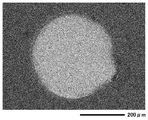
- FIG. 2 is an SEM photograph of the copper foil substrate side after the impact share test before the aging treatment of Example 10
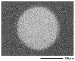
- FIG. 3 is an SEM photograph of the copper foil substrate side after the impact share test after 100 hours of the aging treatment of Example 10.
- the aging treatment does not significantly change the state of the sheared surface of the solder joint.
- Ge having a small solid solubility with respect to Sn which is a main component of the lead-free solder alloy at the time of joining has a solid solubility limit at the time of solidification of the solder alloy. It is assumed that the above elements are precipitated and contribute to strengthening of the alloy and improvement of the bonding strength, the state is maintained even after aging treatment at a high temperature, the reduction of the bonding strength is small, and it is assumed that it is strongly maintained. .
- Test Example 3 Impact Share Test 2
- Method 1 1) In the same procedure as in Test Example 1, a part of the measurement sample manufactured using the 0.5 mm-diameter spherical solder balls made of the lead-free solder alloy obtained in Examples 1 to 10 was kept at 150 ° C. Aged for 100 hours in an electric furnace. 2) The measurement sample and the measurement sample subjected to the aging treatment are set in an impact share tester (4000HS, manufactured by DAGE). 3) The measurement was performed at three different speeds of 10 mm / sec, 1000 mm / sec, and 2000 mm / sec, and the shear load stress was measured. Further, the maximum value (Max force) of the shear load stress was evaluated as the bonding strength.
- An impact share tester 4000HS, manufactured by DAGE
- the lead-free solder alloys obtained in Examples 1 to 10 all meet the acceptance criteria, and have a high shear rate of 1000 mm / s after aging treatment under a high temperature environment of 150 ° C. It can be seen that the bonding strength is high and maintained even at the speed.
- the joining characteristics of the lead-free solder alloys of Examples 2 to 5 are excellent, and these are all 0.1 to 2.0% by mass of Cu, 0.01 to 1.0% by mass of Ni, and 0.001 to 2.
- Pb-free solder that satisfies these contents because it contains 0% by mass and the ratio of Ge content to Cu (Ge / Cu) is adjusted to the range of 0.005 to 0.5. It can be seen that the joining characteristics of the alloy are excellent.
- the lead-free solder alloys of Examples 6 to 10 all had Cu of 0.1 to 2.0% by mass, Ni of 0.01 to 1.0% by mass, Ge of 0.001 to 2.0% by mass, and Bi of 0.1 to 2.0% by mass. These are contained in an amount of 8.0% by mass, 0.1 to 6.5% by mass of Sb, and the ratio of Bi to Sb (Bi / Sb) adjusted to 0.02 to 50. It can be understood that the lead-free solder alloy satisfying the content of the alloy also has excellent bonding characteristics.
- each metal component was mixed to prepare a lead-free solder alloy so that the composition shown in Table 5 was obtained.
- the obtained lead-free solder alloy was evaluated in the same manner as in Test Example 3 and evaluated according to the following criteria.
- evaluation methods When the measured value without aging treatment was 7N or more, and the rate of change after aging treatment was 60% or more, it was judged as pass ( ⁇ ), and when less than 60%, it was judged as unacceptable (x).
- the standard ( ⁇ ) was defined as a value less than 7N measured without aging or a change of less than 60% after aging.
- Table 6 shows the results.
- the present invention has excellent creep characteristics, further has a strong bonding strength, and has a high bonding reliability even under a severe use environment exposed to a high temperature for a long time. It can be expected to be widely applied to electronic devices and the like that are used in a strong bonding strength and in a severe use environment, as well as the bonding.
Landscapes
- Chemical & Material Sciences (AREA)
- Engineering & Computer Science (AREA)
- Mechanical Engineering (AREA)
- Materials Engineering (AREA)
- Metallurgy (AREA)
- Organic Chemistry (AREA)
- Electric Connection Of Electric Components To Printed Circuits (AREA)
Priority Applications (2)
| Application Number | Priority Date | Filing Date | Title |
|---|---|---|---|
| CN201980062723.5A CN112752630A (zh) | 2018-08-10 | 2019-09-26 | 无铅焊料合金 |
| KR1020217011906A KR102853795B1 (ko) | 2018-08-10 | 2019-09-26 | 무연땜납합금 |
Applications Claiming Priority (3)
| Application Number | Priority Date | Filing Date | Title |
|---|---|---|---|
| JP2018151991 | 2018-08-10 | ||
| JP2018181045A JP7287606B2 (ja) | 2018-08-10 | 2018-09-26 | 鉛フリーはんだ合金 |
| JP2018-181045 | 2018-09-26 |
Publications (1)
| Publication Number | Publication Date |
|---|---|
| WO2020067307A1 true WO2020067307A1 (ja) | 2020-04-02 |
Family
ID=69620807
Family Applications (1)
| Application Number | Title | Priority Date | Filing Date |
|---|---|---|---|
| PCT/JP2019/037903 Ceased WO2020067307A1 (ja) | 2018-08-10 | 2019-09-26 | 鉛フリーはんだ合金 |
Country Status (4)
| Country | Link |
|---|---|
| JP (1) | JP7287606B2 (enExample) |
| KR (1) | KR102853795B1 (enExample) |
| CN (1) | CN112752630A (enExample) |
| WO (1) | WO2020067307A1 (enExample) |
Cited By (1)
| Publication number | Priority date | Publication date | Assignee | Title |
|---|---|---|---|---|
| EP4140636A1 (en) * | 2021-08-27 | 2023-03-01 | Senju Metal Industry Co., Ltd. | Solder alloy and solder joint |
Families Citing this family (2)
| Publication number | Priority date | Publication date | Assignee | Title |
|---|---|---|---|---|
| JP2023060639A (ja) * | 2021-10-18 | 2023-04-28 | Tdk株式会社 | はんだ組成物および電子部品 |
| CN114055010A (zh) * | 2021-11-05 | 2022-02-18 | 安徽工业大学 | 一种含微量Ge的铜基合金钎料、制备方法及其钎焊方法 |
Citations (5)
| Publication number | Priority date | Publication date | Assignee | Title |
|---|---|---|---|---|
| JP2016129908A (ja) * | 2014-04-30 | 2016-07-21 | 株式会社日本スペリア社 | 鉛フリーはんだ合金 |
| JP2017087248A (ja) * | 2015-11-08 | 2017-05-25 | 株式会社日本スペリア社 | はんだペースト組成物 |
| JP2018043265A (ja) * | 2016-09-13 | 2018-03-22 | 千住金属工業株式会社 | はんだ合金、はんだボールおよびはんだ継手 |
| WO2018174162A1 (ja) * | 2017-03-23 | 2018-09-27 | 株式会社日本スペリア社 | はんだ継手 |
| JP2019141881A (ja) * | 2018-02-21 | 2019-08-29 | 千住金属工業株式会社 | 鉛フリーはんだ合金 |
Family Cites Families (6)
| Publication number | Priority date | Publication date | Assignee | Title |
|---|---|---|---|---|
| WO1999048639A1 (en) | 1998-03-26 | 1999-09-30 | Nihon Superior Sha Co., Ltd. | Leadless solder |
| CN101288923A (zh) * | 2008-02-27 | 2008-10-22 | 重庆机电职业技术学院 | 一种低铜亚共晶Sn-Cu无铅钎料 |
| JP4968381B2 (ja) * | 2008-04-23 | 2012-07-04 | 千住金属工業株式会社 | 鉛フリーはんだ |
| JP2011156558A (ja) * | 2010-01-30 | 2011-08-18 | Nihon Superior Co Ltd | 鉛フリーはんだ合金 |
| WO2012131861A1 (ja) * | 2011-03-28 | 2012-10-04 | 千住金属工業株式会社 | 鉛フリーはんだボール |
| GR1009565B (el) | 2016-07-14 | 2019-08-06 | Galenica Α.Ε. | Νεα παραγωγα 1,2,4-τριαζολο-[3,4-b]-1,3,4-θειαδιαζολιων |
-
2018
- 2018-09-26 JP JP2018181045A patent/JP7287606B2/ja active Active
-
2019
- 2019-09-26 KR KR1020217011906A patent/KR102853795B1/ko active Active
- 2019-09-26 WO PCT/JP2019/037903 patent/WO2020067307A1/ja not_active Ceased
- 2019-09-26 CN CN201980062723.5A patent/CN112752630A/zh active Pending
Patent Citations (5)
| Publication number | Priority date | Publication date | Assignee | Title |
|---|---|---|---|---|
| JP2016129908A (ja) * | 2014-04-30 | 2016-07-21 | 株式会社日本スペリア社 | 鉛フリーはんだ合金 |
| JP2017087248A (ja) * | 2015-11-08 | 2017-05-25 | 株式会社日本スペリア社 | はんだペースト組成物 |
| JP2018043265A (ja) * | 2016-09-13 | 2018-03-22 | 千住金属工業株式会社 | はんだ合金、はんだボールおよびはんだ継手 |
| WO2018174162A1 (ja) * | 2017-03-23 | 2018-09-27 | 株式会社日本スペリア社 | はんだ継手 |
| JP2019141881A (ja) * | 2018-02-21 | 2019-08-29 | 千住金属工業株式会社 | 鉛フリーはんだ合金 |
Cited By (2)
| Publication number | Priority date | Publication date | Assignee | Title |
|---|---|---|---|---|
| EP4140636A1 (en) * | 2021-08-27 | 2023-03-01 | Senju Metal Industry Co., Ltd. | Solder alloy and solder joint |
| US11992902B2 (en) | 2021-08-27 | 2024-05-28 | Senju Metal Industry Co., Ltd. | Solder alloy and solder joint |
Also Published As
| Publication number | Publication date |
|---|---|
| JP7287606B2 (ja) | 2023-06-06 |
| KR20210062060A (ko) | 2021-05-28 |
| JP2020025982A (ja) | 2020-02-20 |
| KR102853795B1 (ko) | 2025-09-01 |
| CN112752630A (zh) | 2021-05-04 |
Similar Documents
| Publication | Publication Date | Title |
|---|---|---|
| JP6624322B1 (ja) | はんだ合金、はんだボール、はんだプリフォーム、はんだペースト及びはんだ継手 | |
| JP6339993B2 (ja) | 鉛フリーはんだ合金 | |
| KR102207301B1 (ko) | 고신뢰성의 무연 납땜 합금 | |
| WO2017164194A1 (ja) | 鉛フリーはんだ合金、フラックス組成物、ソルダペースト組成物、電子回路基板および電子制御装置 | |
| KR20180006928A (ko) | 가혹한 환경의 전자장치 적용을 위한 고신뢰성 무연 땜납 합금 | |
| WO2012056753A1 (ja) | 低銀はんだ合金およびはんだペースト組成物 | |
| JP2006524572A (ja) | Sn、AgおよびCuからなるはんだ物質 | |
| WO2018174162A1 (ja) | はんだ継手 | |
| EP3590652B1 (en) | Solder alloy, solder junction material, and electronic circuit substrate | |
| JP2002018589A (ja) | 鉛フリーはんだ合金 | |
| CN111683785A (zh) | 焊料合金、焊膏、焊球、带芯焊料及焊接接头 | |
| WO2020067307A1 (ja) | 鉛フリーはんだ合金 | |
| JP4135268B2 (ja) | 無鉛はんだ合金 | |
| TWI695893B (zh) | 銲錫膏 | |
| JP2006255784A (ja) | 無鉛ハンダ合金 | |
| JP4770733B2 (ja) | はんだ及びそれを使用した実装品 | |
| JP3673021B2 (ja) | 電子部品実装用無鉛はんだ | |
| JP2016215277A (ja) | はんだ合金およびそれを用いた実装構造体 | |
| JP4359983B2 (ja) | 電子部品の実装構造体およびその製造方法 | |
| JP2008221330A (ja) | はんだ合金 | |
| JP2019136776A (ja) | はんだ接合方法 | |
| JP2019081201A (ja) | 鉛フリーはんだ合金、ソルダペースト組成物、電子回路基板および電子制御装置 | |
| JP3423387B2 (ja) | 電子部品用はんだ合金 | |
| KR20190028985A (ko) | 납 프리 땜납 합금, 전자 회로 기판 및 전자 제어 장치 | |
| WO2016185674A1 (ja) | はんだ合金およびそれを用いた実装構造体 |
Legal Events
| Date | Code | Title | Description |
|---|---|---|---|
| 121 | Ep: the epo has been informed by wipo that ep was designated in this application |
Ref document number: 19865485 Country of ref document: EP Kind code of ref document: A1 |
|
| NENP | Non-entry into the national phase |
Ref country code: DE |
|
| ENP | Entry into the national phase |
Ref document number: 20217011906 Country of ref document: KR Kind code of ref document: A |
|
| 122 | Ep: pct application non-entry in european phase |
Ref document number: 19865485 Country of ref document: EP Kind code of ref document: A1 |
|
| WWG | Wipo information: grant in national office |
Ref document number: 1020217011906 Country of ref document: KR |