WO2020066419A1 - ロボットシステム - Google Patents
ロボットシステム Download PDFInfo
- Publication number
- WO2020066419A1 WO2020066419A1 PCT/JP2019/033354 JP2019033354W WO2020066419A1 WO 2020066419 A1 WO2020066419 A1 WO 2020066419A1 JP 2019033354 W JP2019033354 W JP 2019033354W WO 2020066419 A1 WO2020066419 A1 WO 2020066419A1
- Authority
- WO
- WIPO (PCT)
- Prior art keywords
- holding
- held
- unit
- hands
- hand
- Prior art date
- Legal status (The legal status is an assumption and is not a legal conclusion. Google has not performed a legal analysis and makes no representation as to the accuracy of the status listed.)
- Ceased
Links
Images


Classifications
-
- B—PERFORMING OPERATIONS; TRANSPORTING
- B25—HAND TOOLS; PORTABLE POWER-DRIVEN TOOLS; MANIPULATORS
- B25J—MANIPULATORS; CHAMBERS PROVIDED WITH MANIPULATION DEVICES
- B25J9/00—Program-controlled manipulators
- B25J9/16—Program controls
- B25J9/1612—Program controls characterised by the hand, wrist, grip control
-
- B—PERFORMING OPERATIONS; TRANSPORTING
- B25—HAND TOOLS; PORTABLE POWER-DRIVEN TOOLS; MANIPULATORS
- B25J—MANIPULATORS; CHAMBERS PROVIDED WITH MANIPULATION DEVICES
- B25J13/00—Controls for manipulators
- B25J13/08—Controls for manipulators by means of sensing devices, e.g. viewing or touching devices
-
- B—PERFORMING OPERATIONS; TRANSPORTING
- B25—HAND TOOLS; PORTABLE POWER-DRIVEN TOOLS; MANIPULATORS
- B25J—MANIPULATORS; CHAMBERS PROVIDED WITH MANIPULATION DEVICES
- B25J15/00—Gripping heads and other end effectors
- B25J15/02—Gripping heads and other end effectors servo-actuated
- B25J15/0253—Gripping heads and other end effectors servo-actuated comprising parallel grippers
- B25J15/0293—Gripping heads and other end effectors servo-actuated comprising parallel grippers having fingers directly connected to actuator
-
- B—PERFORMING OPERATIONS; TRANSPORTING
- B25—HAND TOOLS; PORTABLE POWER-DRIVEN TOOLS; MANIPULATORS
- B25J—MANIPULATORS; CHAMBERS PROVIDED WITH MANIPULATION DEVICES
- B25J15/00—Gripping heads and other end effectors
- B25J15/06—Gripping heads and other end effectors with vacuum or magnetic holding means
- B25J15/0616—Gripping heads and other end effectors with vacuum or magnetic holding means with vacuum
- B25J15/0691—Suction pad made out of porous material, e.g. sponge or foam
-
- B—PERFORMING OPERATIONS; TRANSPORTING
- B25—HAND TOOLS; PORTABLE POWER-DRIVEN TOOLS; MANIPULATORS
- B25J—MANIPULATORS; CHAMBERS PROVIDED WITH MANIPULATION DEVICES
- B25J15/00—Gripping heads and other end effectors
- B25J15/08—Gripping heads and other end effectors having finger members
-
- B—PERFORMING OPERATIONS; TRANSPORTING
- B25—HAND TOOLS; PORTABLE POWER-DRIVEN TOOLS; MANIPULATORS
- B25J—MANIPULATORS; CHAMBERS PROVIDED WITH MANIPULATION DEVICES
- B25J19/00—Accessories fitted to manipulators, e.g. for monitoring, for viewing; Safety devices combined with or specially adapted for use in connection with manipulators
- B25J19/02—Sensing devices
- B25J19/021—Optical sensing devices
- B25J19/023—Optical sensing devices including video camera means
-
- B—PERFORMING OPERATIONS; TRANSPORTING
- B25—HAND TOOLS; PORTABLE POWER-DRIVEN TOOLS; MANIPULATORS
- B25J—MANIPULATORS; CHAMBERS PROVIDED WITH MANIPULATION DEVICES
- B25J9/00—Program-controlled manipulators
- B25J9/0084—Program-controlled manipulators comprising a plurality of manipulators
- B25J9/0087—Dual arms
-
- B—PERFORMING OPERATIONS; TRANSPORTING
- B25—HAND TOOLS; PORTABLE POWER-DRIVEN TOOLS; MANIPULATORS
- B25J—MANIPULATORS; CHAMBERS PROVIDED WITH MANIPULATION DEVICES
- B25J9/00—Program-controlled manipulators
- B25J9/02—Program-controlled manipulators characterised by movement of the arms, e.g. cartesian coordinate type
- B25J9/04—Program-controlled manipulators characterised by movement of the arms, e.g. cartesian coordinate type by rotating at least one arm, excluding the head movement itself, e.g. cylindrical coordinate type or polar coordinate type
- B25J9/041—Cylindrical coordinate type
- B25J9/042—Cylindrical coordinate type comprising an articulated arm
- B25J9/043—Cylindrical coordinate type comprising an articulated arm double selective compliance articulated robot arms [SCARA]
-
- B—PERFORMING OPERATIONS; TRANSPORTING
- B25—HAND TOOLS; PORTABLE POWER-DRIVEN TOOLS; MANIPULATORS
- B25J—MANIPULATORS; CHAMBERS PROVIDED WITH MANIPULATION DEVICES
- B25J9/00—Program-controlled manipulators
- B25J9/16—Program controls
- B25J9/1679—Program controls characterised by the tasks executed
- B25J9/1682—Dual arm manipulator; Coordination of several manipulators
-
- B—PERFORMING OPERATIONS; TRANSPORTING
- B25—HAND TOOLS; PORTABLE POWER-DRIVEN TOOLS; MANIPULATORS
- B25J—MANIPULATORS; CHAMBERS PROVIDED WITH MANIPULATION DEVICES
- B25J9/00—Program-controlled manipulators
- B25J9/16—Program controls
- B25J9/1694—Program controls characterised by use of sensors other than normal servo-feedback from position, speed or acceleration sensors, perception control, multi-sensor controlled systems, sensor fusion
- B25J9/1697—Vision controlled systems
-
- G—PHYSICS
- G06—COMPUTING OR CALCULATING; COUNTING
- G06T—IMAGE DATA PROCESSING OR GENERATION, IN GENERAL
- G06T7/00—Image analysis
- G06T7/60—Analysis of geometric attributes
-
- G—PHYSICS
- G05—CONTROLLING; REGULATING
- G05B—CONTROL OR REGULATING SYSTEMS IN GENERAL; FUNCTIONAL ELEMENTS OF SUCH SYSTEMS; MONITORING OR TESTING ARRANGEMENTS FOR SUCH SYSTEMS OR ELEMENTS
- G05B2219/00—Program-control systems
- G05B2219/30—Nc systems
- G05B2219/39—Robotics, robotics to robotics hand
- G05B2219/39109—Dual arm, multiarm manipulation, object handled in cooperation
-
- G—PHYSICS
- G05—CONTROLLING; REGULATING
- G05B—CONTROL OR REGULATING SYSTEMS IN GENERAL; FUNCTIONAL ELEMENTS OF SUCH SYSTEMS; MONITORING OR TESTING ARRANGEMENTS FOR SUCH SYSTEMS OR ELEMENTS
- G05B2219/00—Program-control systems
- G05B2219/30—Nc systems
- G05B2219/40—Robotics, robotics mapping to robotics vision
- G05B2219/40607—Fixed camera to observe workspace, object, workpiece, global
Definitions
- the present invention relates to a robot system for performing a position change and the like by holding a holding object such as a box with a robot hand.
- both arms are provided with a five-fingered hand portion, and one or two arms, one or several fingers or the whole of one arm, and several fingers of both arms are provided in accordance with an object to be held.
- a device that selects holding by both arms as a whole for example, see Patent Document 1.
- Patent Document 2 there is a technique in which one or a plurality of articles are picked up from an article transport tray by one or both hands of a double arm in an articulated dual arm robot (see, for example, Patent Document 2). .
- Patent Document 1 since the number of fingers and the number of arms are properly used depending on the size of the holding object, it is necessary to finely control the movement of the finger according to the holding object. It is difficult to efficiently hold and transfer the.
- Patent Document 2 describes that one or a plurality of components are picked up from a component transport tray by one or both of the dual-arm hands, but does not disclose the efficient use of the dual-arm hands. .
- an object of the present invention is to provide a robot system that can appropriately use two hands and appropriately hold holding objects having different sizes to perform a position change or the like.
- a robot system includes two arms each having a hand at a tip thereof, and a robot control unit that controls a movement of the arm, wherein the hand can be opened and closed.
- a holding unit wherein the robot control unit determines a number of the hands that hold the holding object based on a size of the holding object; and a hand number determination unit that determines the number of hands that hold the holding object.
- the number of the hands is 1, the holding unit is opened to hold the held object on the inner surface of one hand, and when the number of the hands determined by the hand number determination unit is 2, the holding is performed.
- a holding control unit that controls to close the unit and hold the holding object on the outer surfaces of the two hands.
- the robot control unit determines the number of hands holding the held object by the hand number determination unit based on the size of the held object.
- the holding part of one hand is opened to hold the held object on the inner surface of the holding part, and when the number of hands is two, the holding parts of the two hands are closed and two hands are held.
- the holding control unit controls the holding object to be held on the outer surfaces of the two holding units. Therefore, it is possible to quickly hold and change the position using different surfaces of the holding unit according to the size of the held object.
- the image processing apparatus further includes: a camera configured to capture the held object; and an image processing unit configured to analyze an image captured by the camera, wherein the robot control unit determines at least a size of the held object based on the image processed by the image processing unit.
- the number of hands may be determined by the hand number determination unit based on the calculated size of the held object.
- the size of the held object is calculated from the analysis result of the image captured by the camera, and one hand or two hands is determined according to the size of the held object, and the held object is efficiently determined.
- the position can be changed while being held.
- the holding unit includes two holding plates that open and close in parallel in an opposed state, and when the robot control unit determines that the number of hands determination unit determines to hold the held object with the one hand, 1
- the holding plate of one of the hands may be opened to hold the holding object on the inner surface of the holding plate.
- the holding portion can be opened and the holding object can be efficiently held on the inner surface of the holding plate. Moreover, even in a state where a plurality of holding objects are arranged, the holding plate can be inserted and held between the holding objects.
- the holding unit includes two holding plates that open and close in parallel in an opposed state, and when the robot control unit determines that the hand number determination unit determines to hold the held object with the two hands, The holding plate of one of the hands may be closed to hold the holding object on an outer surface of the holding plate.
- the holding portion can be closed and the holding object can be efficiently held on the outer surface of the holding plate. Moreover, even in a state where a plurality of holding objects are arranged, the holding plate can be inserted and held between the holding objects.
- an adsorbing section for adsorbing the holding object may be further provided near the holding section.
- This “holding” includes holding by holding the holding object by the suction unit, holding by holding the holding object by the holding unit, and holding by holding the holding object by the suction unit.
- the suction unit may include a suction pad provided on a surface of the holding unit that holds the holding object, and may further include a suction device that suctions from the suction pad.
- the suction unit may include a suction hole provided on a surface of the holding unit that holds the holding object, and further include a suction device that suctions from the suction hole.
- the holding portion has a fixed plate and a movable plate arranged in parallel on both sides of the fixed plate, and the movable plate opens and closes in parallel with the fixed plate, and is closed.
- the fixed plate may be configured to be in a state of being juxtaposed on both sides of the fixed plate, and the fixed plate may include the suction portion in a direction in which the movable plate opens and closes.
- the holding portion is arranged in parallel with the fixed plate when the movable plate is closed, and the holding object can be suctioned and held by the suction portion provided on the fixed plate between the movable plates. Moreover, even when the movable plate is opened, the holding object can be sucked and held by the suction portion provided on the fixed plate. Therefore, the holding object can be held by suction by the suction unit using either the two hands or the one hand.
- the suction unit includes a suction nozzle that can move forward and backward in a direction that intersects the opening and closing direction of the holding unit, and moves the suction nozzle according to the weight of the holding object held by the holding unit. May be configured to advance toward and to suck the holding object.
- the two arms may be configured as a double-armed type that can pivot around a first axis provided on a base.
- the dual-arm robot provided on one base opens one holding unit provided on one of the two arms to hold the holding object,
- the operation of closing the holding portion and holding the holding object with the two provided on both of the arms can be efficiently performed, and the holding object having a different size can be quickly held and the position can be changed.
- the holding unit when the number of hands determined based on the size of the held object is 1, the holding unit is opened to hold the held object, and when the number of hands is 2, the holding unit is closed. Is controlled so that the holding object is held by the two holding units. This makes it possible to quickly hold and change positions according to the size of the held object using the holding units of the two hands.
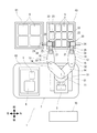
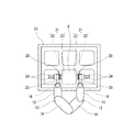
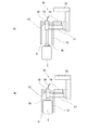
- FIG. 1 is a plan view showing a robot system according to one embodiment of the present invention.
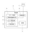
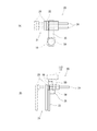
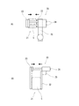
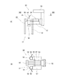
- FIG. 2 is a block diagram showing functions provided in the control device in the robot system shown in FIG. 3A and 3B are drawings showing a first hand of the robot system shown in FIG. 1, wherein FIG. 3A is a plan view and FIG. 3B is a front view.
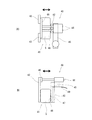
- FIG. 4 is a plan view showing a state in which a small holding object is held with one hand of the robot system shown in FIG. 5A and 5B are detailed views of a state in which the holding object is held by one hand shown in FIG. 4, in which FIG. 5A is a plan view and FIG. 5B is a front view.
- FIG. 5A is a plan view
- FIG. 5B is a front view.
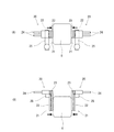
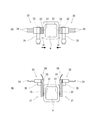
- FIG. 6 is a plan view showing a state where a large holding object is held by both hands of the robot system shown in FIG. 7A and 7B are detailed views of a state where the holding object is held by both hands shown in FIG. 6, where FIG. 7A is a plan view and FIG. 7B is a front view.
- FIG. 8 is a front view showing a third hand obtained by adding a suction function to the first hand shown in FIG.
- FIG. 9 is an enlarged view showing the suction mechanism of the third hand in FIG. 8, (A) is a front view of the first example, and (B) is a front view of the second example.
- FIGS. 10A and 10B are diagrams showing a state in which the third hand shown in FIG. 8 holds a holding object, wherein FIG.
- FIGS. 11A and 11B are diagrams showing a fifth hand having a suction function in a form different from that of FIG. 8, in which FIG. 11A is a plan view and FIG. 11B is a front view.
- 12A and 12B are diagrams illustrating a state in which the fifth hand illustrated in FIG. 11 holds a held object, wherein FIG. 12A is a plan view and FIG. 12B is a front view.
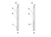
- FIGS. 13A and 13B are views showing a fifth hand having a suction function in a different form from FIG. 8, in which FIG. 13A is a front view, and FIG.
- FIG. 13B is a cross-sectional view taken along the line XIII-XIII shown in FIG.
- FIGS. 14A and 14B are diagrams showing a state in which the fifth hand (one hand) shown in FIG. 13 holds the held object.
- FIG. 14A is a front view showing a state in which the held object is held only by the suction function, and FIG. It is a front view showing the state where it holds by both holding functions.
- FIGS. 15A and 15B are diagrams showing a state in which the holding object is held by the fifth hand (both hands) shown in FIG. 13.
- FIG. 15A is a front view showing a state in which the holding object is held only by the suction function, and FIG. It is a front view showing the state where it holds by both holding functions.
- a robot system 1 including a dual-arm robot 10 will be described as an example.
- a small holding object 5 held by one hand (hereinafter, also referred to as “first holding object 5”) and a large holding object 6 held by both hands (hereinafter, referred to as “second holding object 6”)
- the types of the holding objects may be two or more types, and are not limited to two types.
- one arm 12 (13) is also referred to as "one arm”
- the two arms 12, 13 are also referred to as “both arms”
- one hand 20 is referred to as "one hand”
- the two hands 20 are referred to as "both hands”.
- the concept of the front, rear, left, and right directions in the specification and the claims is the same as the concept of the front, rear, left, and right directions in plan view shown in FIG.
- FIG. 1 is a plan view showing a robot system 1 according to one embodiment.
- FIG. 2 is a block diagram showing functions provided in the control device 70 in the robot system 1 shown in FIG. 3A and 3B are drawings showing the hand 20 of the robot system 1 shown in FIG. 1, wherein FIG. 3A is a plan view and FIG. 3B is a front view.
- the robot 10 in this embodiment has two arms, a first arm 12 (right arm) and a second arm 13 (left arm).
- the two arms 12 and 13 are configured as a double-arm type that can turn around a first axis S1 in the vertical direction provided on the base 11.
- the two arms 12, 13 have a first link 14, a second link 15, and a third link 16, respectively.
- the first link 14 is rotatable in a horizontal direction about a first axis S1 of the base 11.
- the second link 15 is rotatable in the horizontal direction about a vertical second axis S2 at the distal end of the first link 14.
- the third link 16 is provided below the distal end of the second link 15.
- the third link 16 is formed of a member that can swing about a third axis S3 in a horizontal direction orthogonal to the paper surface. (FIG. 3).
- the number of movable axes of the robot 10 is not limited to this example.
- the first hand 20 is provided at the tip of the third link 16.
- the vertical position of the first hand 20 can be adjusted by swinging the components of the third link 16 in the vertical direction about the third axis S3.
- the first hand 20 is rotatable horizontally with respect to the third link 16 about a fourth axis S4 in the vertical direction. Since the first hand 20 of the first arm 12 and the first hand 20 of the second arm 13 are symmetrical and have the same configuration, they are denoted by the same reference numerals. Details of the first hand 20 will be described later.
- one of the two first arms 12 or the second arms 13 can be used depending on the size of the holding objects 5, 6, and the like.
- the operation of holding the first holding object 5 and the operation of holding the second holding object 6 with the first arm 12 and the second arm 13 can be efficiently performed in a small installation space.
- the stereo camera 3 is provided near the robot 10.
- the stereo camera 3 is provided at a position where the holding objects 5 and 6 can be imaged.
- the stereo camera 3 can be provided above the rear side of the base 11.
- the control device 70 includes a processor, a volatile memory, a nonvolatile memory, and an I / O interface serving as a receiving unit and an output unit.
- the control device 70 has a storage unit 71 and a robot control unit 72.
- the storage unit 71 is realized by a volatile memory and a nonvolatile memory.
- the robot control unit 72 is realized by the processor performing arithmetic processing of the coordinates of the links 14 to 16 and the reference position of the first hand 20 using a volatile memory based on a program stored in a nonvolatile memory. .
- the robot control unit 72 outputs an operation amount to each drive unit of the first arm 12 and the second arm 13 based on the coordinate position subjected to the arithmetic processing, and receives the operation amount from the drive unit of the first arm 12 and the second arm 13. Each coordinate position is calculated based on the obtained operation signal.
- the control device 70 also controls turning of the base 11.
- the robot control unit 72 includes a hand number determination unit 73 that determines the number of the first hands 20 that hold the holding objects 5 and 6 based on the sizes of the holding objects 5 and 6.
- the robot control unit 72 includes a holding control unit 74.
- the holding control unit 74 opens the holding unit 21 and holds the first held object 5 with one first hand 20;
- the control is performed so that the holding unit 21 is closed and the second holding object 6 is held by the two first hands 20.
- the holding control unit 74 controls opening and closing of each holding unit 21.
- the image processing unit 75 further performs an analysis process on the image of the held object captured by the stereo camera 3.
- the robot control unit 72 calculates at least the size of the held objects 5 and 6 from the image processed by the image processing unit 75 by the held object information calculation unit 76, and based on the calculated sizes of the held objects 5 and 6.
- the number of first hands 20 can be determined by the hand number determination unit 73.
- the image processing unit 75 can also calculate the shapes of the held objects 5 and 6. With this configuration, the size of the holding objects 5 and 6 is calculated based on the image captured by the stereo camera 3, and is held by one first hand 20 according to the size of the holding objects 5 and 6.
- the robot control unit 72 determines whether to hold the holding objects 5 and 6 efficiently by holding the two first hands 20.
- the robot 10 takes out one small first holding object 5 from the first tray 60 and one large second holding object 6 from the second tray 61, and takes out the third holding object 5 from the second tray 61.
- An example in which the position is changed (transferred) to the tray 62 is shown.
- a plurality of first holding objects 5 are arranged on the first tray 60, and a plurality of second holding objects 6 are arranged on the second tray 61.
- the holding part 21 of the robot 10 of this embodiment is a plate material such that the tip can be inserted between the holding objects 5 and 6 arranged.
- the robot 10 and the third tray 62 are provided on the automatic guided vehicle 2, and after the predetermined holding objects 5 and 6 are placed on the third tray 62, the robot 10 and the third tray 62 can be moved by the automatic guided vehicle 2. ing. The operator can remotely operate the two first hands 20 while watching the image captured by the stereo camera 3.
- the first hand 20 has a base attached to the third link 16 and has a fourth link 25 rotatable in a horizontal direction about a fourth axis S4.
- the fourth link 25 is provided with a holding portion 21 at a distal end.
- the holding section 21 has a fixed plate 22 as a holding plate provided on the fourth link 25 and a movable plate 23 as a holding plate opened to be separated from the fixed plate 22.
- the fixed plate 22 and the movable plate 23 are plate members each having a tip portion formed in a spatula shape.
- the movable plate 23 opens and closes in parallel in a state facing the fixed plate 22.
- the movable plate 23 is opened and closed by a holding cylinder 24 provided on the fourth link 25.
- the movable plate 23 can be in an open state separated from the fixed plate 22 by extending the holding cylinder 24 (a state shown by a two-dot chain line).
- the movable plate 23 can be brought into a closed state in which the movable cylinder 23 is brought into close proximity to (including a state in contact with) the fixed plate 22 by reducing the holding cylinder 24.
- the robot system 1 when holding the holding objects 5 and 6 having different sizes, by using one first hand 20 or two first hands 20 properly, the holding is efficiently performed as follows. Position change or the like can be performed.
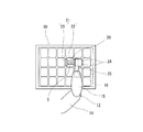
- FIG. 4 is a plan view showing a state where the small first holding object 5 is held by one hand of the robot system 1 shown in FIG. 5A and 5B are detailed views of a state where the first holding object 5 is held with one hand shown in FIG. 4, where FIG. 5A is a plan view and FIG. 5B is a front view.
- the side surface is held by the holding unit 21 provided in one first hand 20.
- the movable plate 23 in the holding unit 21 is separated from the fixed plate 22 by the holding cylinder 24 and opened, so that the movable plate 23 and the fixed plate 22 can sandwich the first holding object 5 from the side. Be placed.
- the first holding object 5 is sandwiched and held by reducing the holding cylinder 24.
- the holding force for holding the first holding object 5 can be made an appropriate force by feeding back the reaction force of the holding cylinder 24.
- the holding portion 21 is a plate-shaped fixed plate 22 and a movable plate 23, the thickness is small, and even when a plurality of first held objects 5 are arranged, the fixed plate 22 and the movable plate can be moved between the first held objects 5.
- the plate 23 can be inserted and held. That is, even when the gap between the arranged first holding objects 5 is narrow, the first holding object 5 can be appropriately held by inserting the plate-shaped fixed plate 22 and the movable plate 23 into the gap.
- the first holding object 5 held by the holding part 21 of one hand is moved to a predetermined position by one arm 12 (13).
- the holding unit 21 is opened and the first holding object 5 is held on the inner surface between the fixed plate 22 and the movable plate 23. It is sandwiched and held. Therefore, quick holding and position change of the first holding object 5 can be performed.
- the first holding object 5 is held by the first arm 12 (right hand) has been described, but even if the first holding object 5 is held by the second arm 13 (left hand), the first arm 12 and the first The first holding object 5 may be held by both arms of the two arms 13.
- FIG. 6 is a plan view showing a state where the large second holding object 6 is held by both hands of the robot system 1 shown in FIG. 7A and 7B are detailed views of a state in which the second holding object 6 is held by both hands shown in FIG. 6, where FIG. 7A is a plan view and FIG. 7B is a front view.
- the holding units provided on the two first arms 12 and the second arms 13 21 holds the side surface.
- the movable plate 23 in each holding unit 21 is closed by being brought close to the fixed plate 22 by the holding cylinder 24, and the two holding units 21 hold the second holding object 6 on the outer surface of the movable plate 23 from the side. It is arranged so that it can be pinched. Thereafter, the holding portions 21 of the first arm 12 and the second arm 13 are closed, and the second holding object 6 is sandwiched and held by the holding portions 21.
- the holding force for holding the second holding object 6 can be made an appropriate force by feeding back the reaction force of the second link 15.
- the holding portion 21 is a plate-like fixed plate 22 and a movable plate 23, the thickness is small even in the closed state, and even when the plurality of second holding objects 6 are arranged, The holding portion 21 can be inserted and held. That is, even when the gap between the arranged second holding objects 6 is narrow, the second holding object 6 can be appropriately held by inserting the plate-shaped holding portion 21 into the gap.
- the second holding object 6 held by the holding portions 21 of both hands is moved to a predetermined position by the two first arms 12 and the second arms 13.
- the holding unit 21 is closed, and the second holding object 6 is held on the outer surfaces of the two movable plates 23. Therefore, quick holding and position change of the second holding object 6 can be performed.
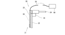
- FIG. 8 is a front view showing a second hand 30 obtained by adding a suction function to the first hand 20 shown in FIG. 9A and 9B are enlarged views showing the suction mechanism of the second hand 30 shown in FIG. 8, wherein FIG. 9A is a front view of the first example, and FIG. 9B is a front view of the second example.
- FIGS. 10A and 10B are diagrams showing a state in which the second holding object 6 is held by the second hand 30 shown in FIG. 8, in which FIG. 10A is a plan view and FIG. 10B is a front view.
- a suction hole 36 is provided in a movable plate 33 provided in the holding portion 31, and a suction pad 37 serving as a suction portion is provided at a tip portion thereof in the outer surface direction of the movable plate 33. Is provided.
- the suction pad 37 and the suction hole 36 communicate with each other, and a suction pipe 39 for suctioning in a vacuum state is connected to a rear end of the suction hole 36.
- the suction pipe 39 is connected to a suction device 80.
- a plurality of suction holes 38 communicating with the suction holes 36 may be provided instead of the suction pads 37.
- the configuration of the suction function is not limited to these.
- the "holding" of the holding object 6 (5) by suction in the documents in the specification and the claims means that the holding object 6 (5) is held by a suction unit (suction pad 37, suction hole 38, suction pad 48 described later). And holding by holding the holding object 6 (5) with the holding portions 31 (41) and holding by the suction portions (37, 38, 48).
- the suction pad 37 provided on the outer surface of the movable plate 33 allows the second hand 30.
- the second holding object 6 can be sucked and held.
- the holding state can be stably maintained even if the surface of the second holding object 6 is deformed during the position change.
- the suction pad 37 is provided on the movable plate 33, but the suction pad 37 may be provided on the movable plate 33 side of the fixed plate 22. In this way, when holding the first holding object 5 with one hand as shown in FIG. 5, the first holding object 5 can be sucked.
- FIGS. 11A and 11B are diagrams showing the third hand 40 having a suction function in a form different from that of FIG. 8, in which FIG. 11A is a plan view and FIG. 11B is a front view.
- FIGS. 12A and 12B are diagrams showing a state where the first holding object 5 is held by the third hand 40 shown in FIG. 11, in which FIG. 12A is a plan view and FIG. 12B is a front view.
- the holding portion 41 of the third hand 40 has a configuration in which the movable plate 43 is provided adjacent to both sides of the fixed plate 42.
- the movable plate 43 is connected by a connecting member 46, and the connecting member 46 is configured to be able to advance and retreat by a holding cylinder 44.
- the movable plate 43 opens and closes in parallel with the fixed plate 42.
- the fixing plate 42 is provided with a suction function.
- a suction hole 47 is provided at a central portion of the fixed plate 42, and a suction pad 48 as a suction portion is provided at a tip end of the suction hole 47 in a direction in which the movable plate 43 of the fixed plate 42 opens and closes.
- a suction pipe 49 for sucking in a vacuum state is connected to the rear end of the suction hole 47.
- the first plate is formed by the inner surfaces of the fixed plate 42 and the movable plate 43 with the movable plate 43 of one hand opened.
- the holding object 5 can be held.
- the first holding object 5 can be sucked by the suction pad 48 by sucking from the suction pipe 49 provided on the fixing plate 42 to make the inside of the suction pad 48 in a vacuum state. Therefore, according to this example, even the first holding object 5 having a soft surface can be held with one hand.
- FIGS. 13A and 13B are views showing a fourth hand 50 having a suction function in a form different from that of FIG. 8, in which FIG. 13A is a front view, and FIG. FIGS. 14A and 14B are diagrams showing a state in which the holding object is held by one hand of the fourth hand 50 shown in FIG. 13, wherein FIG. 14A is a front view showing a state in which the holding object is held only by the suction function, and FIG. It is a front view showing the state where it holds by both holding functions.
- 15A and 15B are diagrams showing a state in which the holding object is held by both hands of the fourth hand 50 shown in FIG. 13, wherein FIG. 15A is a front view showing a state in which the holding object is held only by the suction function, and FIG. It is a front view showing the state where it holds by both holding functions.
- the fourth hand 50 of this embodiment has the same configuration as the first hand 20 in which the movable plate 53 opens and closes with respect to the fixed plate 52.
- a suction nozzle 56 is provided in the front-rear direction of the movable plate 53 as a suction unit that can move up and down toward the first holding object 5 in the vertical direction.
- the suction nozzle 56 has a tip formed of a flexible material, and can suction the holding objects 5 and 6.
- the suction nozzle 56 is provided on a protruding portion 57 that protrudes forward from the fourth link 55 provided with the holding cylinder 54.
- the suction nozzle 56 can be moved up and down in the vertical direction intersecting the opening and closing direction of the movable plate 53 by the moving cylinder 58.
- the suction nozzle 56 is moved by the reciprocating cylinder 58 with the movable plate 53 opened. It is advanced toward the first holding object 5. Then, the first holding object 5 is sucked by the suction nozzle 56. Then, as shown in FIG. 14B, the reciprocating cylinder 58 is retracted to bring the first holding object 5 into a state between the fixed plate 52 and the movable plate 53. After that, the holding cylinder 54 is retracted, and the first holding object 5 is held between the fixed plate 52 and the movable plate 53.
- the suction force of the suction nozzle 56 and the holding force of the fixed plate 52 and the movable plate 53 can be appropriately held with one hand by the suction force of the suction nozzle 56 and the holding force of the fixed plate 52 and the movable plate 53.
- the suction nozzle 56 of both hands is extended, and The second holding object 6 can be held by being sucked by the suction nozzle 56.
- the movable plate 53 of both hands is retracted to a closed state, and both hands are moved.
- the second holding object 6 can be held by the outer surfaces of the movable plates 53 of both hands.
- the holding force of the suction nozzle 56 and the holding force of the holding unit 51 can be appropriately held by both hands.
- the illustrated usage of the fourth hand 50 is an example, and the suction by the suction nozzle 56 and the holding by the holding unit 51 can be combined according to the holding objects 5 and 6.
- the hands 20, 30, 40, 50 having the plate-like fixed plates 22, 2, 42, 52 and the movable plates 23, 33, 43, 53 in the holding portions 21, 31, 41, 51 are used.
- the configuration of the holding portions 21, 31, 41, and 51 is not limited to a plate shape, but may be any opening / closing holding portion, and is not limited to the above embodiment.
- a material for example, a rubber material that increases the frictional resistance may be provided on the surfaces of the holding portions 21, 31, 41, and 51 that hold the holding objects 5, 6.
- the robot 10 is an example, and is not limited to the dual-arm robot 10.
- a configuration having two robots 10 that can respectively control the two hands 20 and 30 may be employed.
Landscapes
- Engineering & Computer Science (AREA)
- Robotics (AREA)
- Mechanical Engineering (AREA)
- Physics & Mathematics (AREA)
- Health & Medical Sciences (AREA)
- General Health & Medical Sciences (AREA)
- Orthopedic Medicine & Surgery (AREA)
- Multimedia (AREA)
- Computer Vision & Pattern Recognition (AREA)
- General Physics & Mathematics (AREA)
- Theoretical Computer Science (AREA)
- Chemical & Material Sciences (AREA)
- Dispersion Chemistry (AREA)
- Geometry (AREA)
- Human Computer Interaction (AREA)
- Manipulator (AREA)
Abstract
先端にハンドを備えた2本のアームと、アームの動きを制御するロボット制御部とを備え、ハンドは、開閉可能な保持部を有し、ロボット制御部は、保持物体の大きさに基づいて保持物体を保持するハンドの数を決定するハンド数決定部と、ハンド数決定部で決定されたハンドの数が1の場合には保持部を開放して1つのハンドの内面で保持物体を保持し、ハンド数決定部で決定されたハンドの数が2の場合には保持部を閉鎖して2つのハンドの外面で保持物体を保持するように制御する保持制御部と、を有するようにする。これにより、2つのハンドを適切に使い分けて保持物体を効率良く保持して位置換えなどができるロボットシステムを提供する。
Description
本発明は、箱体などの保持物体をロボットハンドで保持して位置換えなどを行うロボットシステムに関する。
従来、箱体や梱包物などの保持物体をロボットハンドで保持して位置換えなどを行うロボットシステムがある。例えば、一方のトレイ上に並べられた保持物体を保持して他方のトレイ上に移し換えるようなロボットシステムがある。
このようなロボットシステムの先行技術として、例えば、両腕に5本指のハンド部を備えさせ、保持物体に応じて片腕又は両腕、片腕の数本指又は片腕全体、両腕の数本指、又は両腕全体による保持を選択するものがある(例えば、特許文献1参照)。
また、他の先行技術として、多関節型双腕ロボットにおける双腕のハンドの一方又は両方により、物品搬送トレイから一又は複数の物品を取り上げて作業するものもある(例えば、特許文献2参照)。
ところで、例えば、物流倉庫などにおいてロボットシステムによって位置換えなどを行う保持物体には、様々な大きさや形状の物がある。そして、例えば、大きな保持物体が並べられたトレイと小さな保持物体が並べられたトレイとから、それぞれの保持物体を別のトレイに移し換えるような作業もある。
しかし、上記特許文献1では、保持物体の大きさなどに応じて指の本数、腕の本数を使い分けるため、保持物体に応じて指の動作を細かく制御する必要があり、大きさの異なる保持物体を効率良く保持して移し換えることは難しい。
また、上記特許文献2では、双腕のハンドの一方又は両方で部品搬送トレイから一又は複数の部品を取り上げることは記載されているが、効率良く双腕のハンドを使い分けることについて記載されていない。
そこで、本発明は、2つのハンドを適切に使い分けて大きさの異なる保持物体を効率良く保持して位置換えなどが行えるロボットシステムを提供することを目的とする。
上記目的を達成するために、本発明に係るロボットシステムは、先端にハンドを備えた2本のアームと、前記アームの動きを制御するロボット制御部と、を備え、前記ハンドは、開閉可能な保持部を有し、前記ロボット制御部は、保持物体の大きさに基づいて該保持物体を保持する前記ハンドの数を決定するハンド数決定部と、前記ハンド数決定部で決定された前記ハンドの数が1の場合には前記保持部を開放して1つの前記ハンドの内面で前記保持物体を保持し、前記ハンド数決定部で決定された前記ハンドの数が2の場合には前記保持部を閉鎖して2つの前記ハンドの外面で前記保持物体を保持するように制御する保持制御部と、を有している。
この構成により、ロボット制御部が保持物体の大きさに基づいてハンド数決定部で保持物体を保持するハンド数を決定する。そして、ハンドの数が1の場合は1つのハンドの保持部を開放して保持部の内面で保持物体を保持し、ハンドの数が2の場合は2つのハンドの保持部を閉鎖して2つの保持部の外面で保持物体を保持するように保持制御部で制御される。よって、保持物体の大きさに応じて保持部の異なる面を用いて迅速に保持して位置換えなどが行える。
また、前記保持物体を撮像するカメラと、前記カメラで撮像した画像を解析処理する画像処理部と、を備え、前記ロボット制御部は、前記画像処理部で処理した画像から少なくとも前記保持物体の大きさを保持物体情報算出部で算出し、算出した前記保持物体の大きさに基づいて前記ハンド数決定部で前記ハンドの数を決定するように構成されていてもよい。
このように構成すれば、カメラで撮像した画像の解析結果から保持物体の大きさを算出し、保持物体の大きさに応じて1つのハンドか2つのハンドかを決定して効率良く保持物体を保持して位置換えなどを行うことができる。
また、前記保持部は、対向した状態で平行に開閉する2つの保持板を備え、前記ロボット制御部が、前記ハンド数決定部で前記保持物体を1の前記ハンドで保持すると決定した場合、1つの前記ハンドの前記保持板を開放して該保持板の内面で前記保持物体を保持するように構成されていてもよい。
このように構成すれば、保持物体を1つのハンドで保持する場合、保持部を開放して保持板の内面で保持物体を効率良く保持することができる。しかも、複数の保持物体が並んでいる状態でも、保持物体の間に保持板を挿入して保持することができる。
また、前記保持部は、対向した状態で平行に開閉する2つの保持板を備え、前記ロボット制御部が、前記ハンド数決定部で前記保持物体を2の前記ハンドで保持すると決定した場合、2つの前記ハンドの前記保持板を閉鎖して該保持板の外面で前記保持物体を保持するように構成されていてもよい。
このように構成すれば、保持物体を2つのハンドで保持する場合、保持部を閉鎖して保持板の外面で保持物体を効率良く保持することができる。しかも、複数の保持物体が並んでいる状態でも、保持物体の間に保持板を挿入して保持することができる。
また、前記保持部の近傍に前記保持物体を吸着する吸着部をさらに備えていてもよい。
このように構成すれば、保持物体の表面材質が柔軟な場合でも、吸着部に吸着させて保持することができる。この「保持」は、保持物体を吸着部で吸着することによる保持、保持物体を保持部で保持することに加えて吸着部で吸着することによる保持を含む。
また、前記吸着部は、前記保持部の前記保持物体を保持する面に設けられた吸着パッドを有し、前記吸着パッドから吸引する吸引機をさらに備えていてもよい。
このように構成すれば、保持物体を保持部で保持する動作時に、吸着パッドから吸引することで表面が変形するような保持物体であっても適切に保持することができる。
また、前記吸着部は、前記保持部の前記保持物体を保持する面に設けられた吸着穴を有し、前記吸着穴から吸引する吸引機をさらに備えていてもよい。
このように構成すれば、保持物体を保持部で保持する動作時に、吸着穴から吸引することで表面が変形するような保持物体であっても適切に保持することができる。
また、前記保持部は、固定板と、前記固定板の両側方に並列するように配置された可動板と、を有し、前記可動板は、前記固定板に対して平行に開閉し、閉鎖した状態で前記固定板の両側方に並列した状態となるように構成され、前記固定板は、前記可動板が開閉する方向に前記吸着部を備えていてもよい。
このように構成すれば、可動板を閉鎖した状態で固定板と並列した状態の保持部となり、可動板の間の固定板に備えられた吸着部によって保持物体を吸着して保持することができる。しかも、可動板を開放した状態でも、固定板に備えられた吸着部によって保持物体を吸着して保持することができる。よって、保持物体を、2つのハンド及び1つのハンドのいずれでも吸着部による吸着で保持することができる。
また、前記吸着部は、前記保持部の開閉方向に対して交差する方向に進退可能な吸着ノズルを有し、前記保持部で保持した前記保持物体の重量に応じて前記吸着ノズルを前記保持物体に向けて進出させて該保持物体を吸着するように構成されていてもよい。
このように構成すれば、保持物体が大重量である場合などには、保持物体を保持部で保持した状態で吸着ノズルによって保持物体を吸着することで、大きな力で保持物体を保持して位置換えなどを行うことができる。
また、2本の前記アームは基台に備えられた第1軸の回りで旋回可能な双腕型で構成されていてもよい。
このように構成すれば、1つの基台に備えられた双腕型ロボットにより、2本のアームの一方に備えられた1つの保持部を開放して保持物体を保持する動作と、2本のアームの両方に備えられた2つで保持部を閉鎖して保持物体を保持する動作とを効率良く行って、異なる大きさの保持物体を迅速に保持して位置換えなどを行うことができる。
本発明によれば、保持物体の大きさに基づいて決定されたハンドの数が1の場合は保持部を開放して保持物体を保持し、ハンドの数が2の場合は保持部を閉鎖して2つの保持部で保持物体を保持するように制御される。これにより、2つのハンドの保持部を用いて、保持物体の大きさに応じた迅速な保持と位置換えなどが可能となる。
以下、本発明の実施形態を図面に基づいて説明する。以下の実施形態では、双腕型のロボット10を備えたロボットシステム1を例に説明する。また、以下の例では、片手で保持する小さな保持物体5(以下、「第1保持物体5」ともいう)と、両手で保持する大きな保持物体6(以下、「第2保持物体6」という)を例に説明する。保持物体の種類は、2種類以上でもよく、2種類に限定されるものではない。さらに、1本のアーム12(13)を「片腕」、2本のアーム12,13を「両腕」、1つのハンド20を「片手」、2つのハンド20を「両手」ともいう。この明細書及び特許請求の範囲の書類中における前後左右方向の概念は、図1に示す平面視における前後左右方向の概念と一致するものとする。
(ロボットシステムの構成)
図1は、一実施形態に係るロボットシステム1を示す平面図である。図2は、図1に示すロボットシステム1における制御装置70が備える機能を示すブロック図である。図3は、図1に示すロボットシステム1のハンド20を示す図面であり、(A)は平面図、(B)は正面図である。
図1は、一実施形態に係るロボットシステム1を示す平面図である。図2は、図1に示すロボットシステム1における制御装置70が備える機能を示すブロック図である。図3は、図1に示すロボットシステム1のハンド20を示す図面であり、(A)は平面図、(B)は正面図である。
この実施形態におけるロボット10は、第1アーム12(右腕)と第2アーム13(左腕)の2本を備えている。2本のアーム12,13は基台11に備えられた上下方向の第1軸S1の回りで旋回可能な双腕型で構成されている。2本のアーム12,13は、それぞれ第1リンク14、第2リンク15、第3リンク16を有している。第1リンク14は、基台11の第1軸S1を中心にして水平方向に回動可能となっている。第2リンク15は、第1リンク14の先端部における上下方向の第2軸S2を中心にして水平方向に回動可能となっている。第3リンク16は、第2リンク15の先端部における下方に設けられている。第3リンク16は、紙面に対して直交する水平方向の第3軸S3を中心に揺動可能な部材で構成されている。(図3)。ロボット10の可動軸数は、この例に限定されるものではない。
そして、第3リンク16の先端部に、第1ハンド20が備えられている。第1ハンド20は、第3リンク16の構成部材が第3軸S3を中心に上下方向に揺動することによって上下位置の調節が可能となっている。第1ハンド20は、第3リンク16に対して上下方向の第4軸S4を中心にして水平方向に回動可能となっている。第1アーム12の第1ハンド20と、第2アーム13の第1ハンド20は、対称形状で構成は同一で有るため、同一符号を付している。第1ハンド20の詳細は、後述する。
ロボット10を1つの基台11に備えられた双腕型とすることで、保持物体5,6の大きさ等に応じて、2本の第1アーム12又は第2アーム13のいずれか一方で第1保持物体5を保持する動作と、第1アーム12と第2アーム13の2本で第2保持物体6を保持する動作とを、小さな設置スペースで効率良く行うことができる。
また、この実施形態では、ロボット10の近傍にステレオカメラ3が備えられている。ステレオカメラ3は、保持物体5,6を撮像することができる位置に備えられている。例えば、ステレオカメラ3を基台11の後側における上方に備えさせることができる。ステレオカメラ3を備えさせることで、保持物体5,6を立体的に撮像することができる。保持物体5,6を立体的に撮像することで、以下に説明するように、画像解析によって保持物体5,6の大きさを算出することができる。
さらに、ロボットシステム1を制御する制御装置70が備えられている。制御装置70は、プロセッサ、揮発性メモリ、不揮発性メモリ及び受信部及び出力部となるI/Oインターフェース等を有する。
図2に示すように、制御装置70は、記憶部71、ロボット制御部72を有する。記憶部71は、揮発性メモリ及び不揮発性メモリにより実現される。ロボット制御部72は、各リンク14~16及び第1ハンド20の基準位置の座標を、不揮発性メモリに保存されたプログラムに基づいてプロセッサが揮発性メモリを用いて演算処理することで実現される。ロボット制御部72は、演算処理した座標位置に基づいて、第1アーム12と第2アーム13のそれぞれの駆動部に動作量を出力し、第1アーム12と第2アーム13の駆動部から受信した動作信号に基づいて各座標位置を算出する。制御装置70は、基台11の旋回制御も行う。
また、ロボット制御部72は、保持物体5,6の大きさに基づいて、その保持物体5,6を保持する第1ハンド20の数を決定するハンド数決定部73を備えている。ロボット制御部72は、保持制御部74を備えている。保持制御部74は、ハンド数決定部73で決定された第1ハンド20の数が1の場合には保持部21を開放して1つの第1ハンド20で第1保持物体5を保持し、ハンド数決定部73で決定された第1ハンド20の数が2の場合には保持部21を閉鎖して2つの第1ハンド20で第2保持物体6を保持するように制御する。保持制御部74により、各保持部21の開閉制御が行われる。
また、ステレオカメラ3で撮像した保持物体の画像を解析処理する画像処理部75を備えている。ロボット制御部72は、画像処理部75で処理された画像から少なくとも保持物体5,6の大きさを保持物体情報算出部76で算出し、算出された保持物体5,6の大きさに基づいてハンド数決定部73で第1ハンド20の数を決定することができる。画像処理部75により、保持物体5,6の形状を算出することもできる。このようにすれば、ステレオカメラ3で撮像された画像に基づいて保持物体5,6の大きさを算出し、保持物体5,6の大きさに応じて1つの第1ハンド20で保持するか、2つの第1ハンド20で保持するかをロボット制御部72で決定して効率良く保持物体5,6を保持することができる。
図1に示すように、この実施形態では、ロボット10によって、小さな第1保持物体5を第1トレイ60から1個、大きな第2保持物体6を第2トレイ61から1個取り出して、第3トレイ62に位置換え(移し替え)する例を示している。第1トレイ60には、複数の第1保持物体5が並べられており、第2トレイ61には、複数の第2保持物体6が並べられている。このため、この実施形態のロボット10の保持部21は、並べられた保持物体5,6の間に先端部が挿入できるような板材となっている。この実施形態では、ロボット10と第3トレイ62とが無人搬送車2に備えられており、第3トレイ62に所定の保持物体5,6を載せた後、無人搬送車2によって移動可能となっている。なお、ステレオカメラ3で撮像された画像を作業者が見ながら、2つの第1ハンド20を遠隔操作することもできる。
図3(A)、(B)に基づいて第1ハンド20の詳細を説明する。なお、以下の説明では、第1アーム12の第1ハンド20を例に説明する。第1ハンド20は、基部が上記第3リンク16に取り付けられており、第4軸S4を中心にして水平方向に回動可能な第4リンク25を有している。第4リンク25は、先端部に保持部21が設けられている。
保持部21は、第4リンク25に設けられた保持板たる固定板22と、この固定板22から離間するように開放される保持板たる可動板23とを有している。この実施形態では、固定板22及び可動板23は、先端部がへら状に形成された板材となっている。可動板23は、固定板22と対向した状態で平行に開閉する。可動板23は、第4リンク25に設けられた保持シリンダ24によって開閉される。可動板23は、保持シリンダ24を伸長することで固定板22から離間させた開放状態にできる(二点鎖線の状態)。可動板23は、保持シリンダ24を縮小することで固定板22と近接(接した状態を含む)させた閉鎖状態にできる。
このロボットシステム1によれば、大きさの異なる保持物体5,6を保持するときに、1つの第1ハンド20又は2つの第1ハンド20を使い分けることで、以下のように効率良く保持して位置換えなどを行うことができる。
(1本のアームの使用形態)
図4は、図1に示すロボットシステム1の片手で小さな第1保持物体5を保持する状態を示す平面図である。図5は、図4に示す片手で第1保持物体5を保持する状態の詳細図であり、(A)は平面図、(B)は正面図である。
図4は、図1に示すロボットシステム1の片手で小さな第1保持物体5を保持する状態を示す平面図である。図5は、図4に示す片手で第1保持物体5を保持する状態の詳細図であり、(A)は平面図、(B)は正面図である。
図示するように、第1トレイ60に並べられた小さな第1保持物体5(例えば、携帯電話などの箱体)の場合、1つの第1ハンド20に備えられた保持部21によって側面が保持される。具体的には、保持部21における可動板23が保持シリンダ24によって固定板22から離間させられて開放され、可動板23と固定板22が第1保持物体5を側面から挟むことができるように配置される。その後、保持シリンダ24を縮小させることで第1保持物体5が挟まれて保持される。第1保持物体5を保持する保持力は、保持シリンダ24の反力をフィードバックすることで適切な力にできる。しかも、保持部21が板状の固定板22と可動板23であるため厚みが薄く、複数の第1保持物体5が並んでいる状態でも、第1保持物体5の間に固定板22と可動板23とを挿入して保持することができる。すなわち、並んだ第1保持物体5の隙間が狭い場合でも、板状の固定板22と可動板23とを隙間に挿入して第1保持物体5を適切に保持することができる。
片手の保持部21で保持された第1保持物体5は、1本のアーム12(13)によって所定位置まで移動させられる。
このように、1本のアーム12(13)で小さな第1保持物体5を保持する場合、保持部21が開放されて固定板22と可動板23との間の内面で第1保持物体5が挟まれて保持される。よって、第1保持物体5の迅速な保持と位置換えなどができる。図では、第1アーム12(右手)で第1保持物体5を保持する例を説明したが、第2アーム13(左手)で第1保持物体5を保持しても、第1アーム12と第2アーム13の両腕でそれぞれ第1保持物体5を保持するようにしてもよい。
(2本のアームの使用形態)
図6は、図1に示すロボットシステム1の両手で大きな第2保持物体6を保持する状態を示す平面図である。図7は、図6に示す両手で第2保持物体6を保持する状態の詳細図であり、(A)は平面図、(B)は正面図である。
図6は、図1に示すロボットシステム1の両手で大きな第2保持物体6を保持する状態を示す平面図である。図7は、図6に示す両手で第2保持物体6を保持する状態の詳細図であり、(A)は平面図、(B)は正面図である。
図示するように、第2トレイ61に並べられた大きな第2保持物体6(例えば、靴などの箱体)の場合、2本の第1アーム12と第2アーム13とに備えられた保持部21によって側面が保持される。具体的には、それぞれの保持部21における可動板23が保持シリンダ24によって固定板22に近接させられて閉鎖され、2つの保持部21が可動板23の外面で第2保持物体6を側面から挟むことができるように配置される。その後、第1アーム12と第2アーム13の保持部21が閉じられて、保持部21によって第2保持物体6が挟まれて保持される。第2保持物体6を保持する保持力は、第2リンク15の反力をフィードバックすることで適切な力にできる。しかも、保持部21が板状の固定板22と可動板23であるため、閉鎖した状態でも厚みが薄く、複数の第2保持物体6が並んでいる状態でも、第2保持物体6の間に保持部21を挿入して保持することができる。すなわち、並んだ第2保持物体6の隙間が狭い場合でも、板状の保持部21を隙間に挿入して第2保持物体6を適切に保持することができる。両手の保持部21で保持された第2保持物体6は、2本の第1アーム12と第2アーム13とによって所定位置まで移動させられる。
このように、2本のアーム12,13で第2保持物体6を保持する場合、保持部21が閉鎖されて、2つの可動板23の外面で第2保持物体6が保持される。よって、第2保持物体6の迅速な保持と位置換えなどができる。
(吸着機能を備えた第2ハンドの例)
図8は、図3に示す第1ハンド20に吸着機能を付加した第2ハンド30を示す正面図である。図9は、図8に示す第2ハンド30の吸着機構を示す拡大図面であり、(A)は第1例の正面図であり、(B)は第2例の正面図である。図10は、図8に示す第2ハンド30で第2保持物体6を保持する状態を示す図面であり、(A)は平面図、(B)は正面図である。
図8は、図3に示す第1ハンド20に吸着機能を付加した第2ハンド30を示す正面図である。図9は、図8に示す第2ハンド30の吸着機構を示す拡大図面であり、(A)は第1例の正面図であり、(B)は第2例の正面図である。図10は、図8に示す第2ハンド30で第2保持物体6を保持する状態を示す図面であり、(A)は平面図、(B)は正面図である。
図8,図9(A)に示す例では、保持部31に設けられた可動板33の内部に吸引穴36が設けられ、その先端部分に可動板33の外面方向に吸着部たる吸着パッド37が設けられている。吸着パッド37と吸引穴36は連通しており、吸引穴36の後端部には真空状態で吸引する吸引パイプ39が接続されている。吸引パイプ39は、吸引機80に接続されている。このようにすることで、可動板33の外面で第2保持物体6を保持する場合、第2保持物体6の表面が柔らかい素材の場合(例えば、ナイロンなど)でも、吸着パッド37による吸着で適切に保持することができる。
なお、図9(B)に示すように、吸着パッド37の代わりに吸引穴36と連通する複数の吸着穴38を設けるようにしてもよい。吸着機能の構成は、これらに限定されるものではない。
この明細書及び特許請求の範囲の書類中における吸着による保持物体6(5)の「保持」は、保持物体6(5)を吸着部(吸着パッド37、吸着穴38、後述する吸着パッド48)で吸着することによる保持、保持物体6(5)を保持部31(41)で保持することに加えて吸着部(37,38,48)で吸着することによる保持を含む。
図10(A)、(B)に示すように、第2ハンド30によれば、表面が柔らかい素材の第2保持物体6であっても、可動板33の外面に設けられた吸着パッド37によって第2保持物体6を吸着して保持することができる。この実施形態では、吸着パッド37によって第2保持物体6を吸着しているため、位置換え中に第2保持物体6の表面が変形しても保持状態を安定して保つことができる。
なお、この例では可動板33に吸着パッド37を設けているが、固定板22の可動板33側に吸着パッド37を設けるようにしてもよい。このようにすれば、上記図5で示すように片手で第1保持物体5を保持するときに、第1保持物体5を吸着することができる。
(吸着機能を備えた第3ハンドの例)
図11は、図8とは異なる形態の吸着機能を備えた第3ハンド40を示す図面であり、(A)は平面図、(B)は正面図である。図12は、図11に示す第3ハンド40で第1保持物体5を保持する状態を示す図面であり、(A)は平面図、(B)は正面図である。
図11は、図8とは異なる形態の吸着機能を備えた第3ハンド40を示す図面であり、(A)は平面図、(B)は正面図である。図12は、図11に示す第3ハンド40で第1保持物体5を保持する状態を示す図面であり、(A)は平面図、(B)は正面図である。
図11に示すように、第3ハンド40の保持部41は、固定板42の両側方に隣接するように可動板43が設けられた構成となっている。可動板43は、連結部材46で連結され、この連結部材46が保持シリンダ44によって進退可能に構成されている。これにより、可動板43は固定板42に対して平行に開閉するようになっている。可動板43を保持シリンダ44で後退させると、固定板42の両側方に並列した状態となる。すなわち、可動板43は、閉鎖した状態では固定板42の両側方に並列した状態となる。そして、固定板42に吸着機能が備えられている。この例では、固定板42の中央部分に吸引穴47が設けられ、固定板42の可動板43が開閉する方向における吸引穴47の先端部に、吸着部たる吸着パッド48が設けられている。吸引穴47の後端部には、真空状態で吸引する吸引パイプ49が接続されている。
図12(A)、(B)に示すように、この実施形態の第3ハンド40によれば、片手の可動板43を開放した状態で、固定板42と可動板43との内面によって第1保持物体5を保持することができる。しかも、固定板42に設けられた吸引パイプ49から吸引して吸着パッド48の内部を真空状態とすることで、吸着パッド48による第1保持物体5の吸着もできる。従って、この例によれば、表面が柔らかい第1保持物体5であっても、片手で保持することができる。
(吸着機能を備えた第4ハンドの例)
図13は、図8とは異なる形態の吸着機能を備えた第4ハンド50を示す図面であり、(A)は正面図、(B)は(A)に示すXIII-XIII断面図である。図14は、図13に示す第4ハンド50の片手で保持物体を保持する状態を示す図面であり、(A)は吸着機能のみで保持する状態を示す正面図、(B)は吸着機能と保持機能の両方で保持する状態を示す正面図である。図15は、図13に示す第4ハンド50の両手で保持物体を保持する状態を示す図面であり、(A)は吸着機能のみで保持する状態を示す正面図、(B)は吸着機能と保持機能の両方で保持する状態を示す正面図である。
図13は、図8とは異なる形態の吸着機能を備えた第4ハンド50を示す図面であり、(A)は正面図、(B)は(A)に示すXIII-XIII断面図である。図14は、図13に示す第4ハンド50の片手で保持物体を保持する状態を示す図面であり、(A)は吸着機能のみで保持する状態を示す正面図、(B)は吸着機能と保持機能の両方で保持する状態を示す正面図である。図15は、図13に示す第4ハンド50の両手で保持物体を保持する状態を示す図面であり、(A)は吸着機能のみで保持する状態を示す正面図、(B)は吸着機能と保持機能の両方で保持する状態を示す正面図である。
図13(A)、(B)に示すように、この実施形態の第4ハンド50は、固定板52に対して可動板53が開閉する構成は第1ハンド20と同一である。そして、可動板53の前後方向に、第1保持物体5に向けて上下方向に進退可能な吸着部たる吸着ノズル56が備えられている。吸着ノズル56は、先端が柔軟な材料で形成されており、保持物体5,6を吸着することができる。吸着ノズル56は、保持シリンダ54が備えられた第4リンク55から前方に突出する突出部57に設けられている。吸着ノズル56は、進退シリンダ58によって可動板53の開閉方向と交差する上下方向に進退可能となっている。
この第4ハンド50によれば、図14(A)に示すように、小さな第1保持物体5であっても重量が大きい場合、可動板53を開放した状態で吸着ノズル56を進退シリンダ58で第1保持物体5に向けて進出させる。そして、吸着ノズル56で第1保持物体5を吸着する。そして、図14(B)に示すように、進退シリンダ58を後退させて、第1保持物体5が固定板52と可動板53との間に位置する状態とする。その後、保持シリンダ54を後退させて固定板52と可動板53とによって第1保持物体5を挟んで保持する。これにより、重量が大きな第1保持物体5であっても、吸着ノズル56による吸着力と固定板52と可動板53による保持力とによって、片手で適切に保持することができる。
また、図15(A)に示すように、上記第4ハンド50によれば、厚みが薄く、表面が柔らかい大きな第2保持物体6であっても、両手の吸着ノズル56を伸長し、これらの吸着ノズル56で第2保持物体6を吸着することで保持することができる。
さらに、図15(B)に示すように、上記第4ハンド50によれば、重量が大きな第2保持物体6であっても、両手の可動板53を後退させて閉じた状態とし、両手の吸着ノズル56で第1保持物体5を吸着した状態で、両手の可動板53の外面によって第2保持物体6を保持することができる。これにより、重量が大きな第2保持物体6であっても、吸着ノズル56による吸着力と保持部51による保持力とによって、両手で適切に保持することができる。図示する第4ハンド50の使用形態は一例であり、保持物体5,6に応じて吸着ノズル56による吸着と保持部51による保持とを組み合わせることができる。
(総括)
以上のように、上記したロボットシステム1によれば、保持物体5,6の大きさに基づいて決定されたハンド20,30,40,50の数が1の場合は保持部21,31,41,51を開放して1つの保持部21,31,41,51の内面で保持物体5,6を保持するように制御される。そして、ハンド20,30,40,50の数が2の場合は保持部21,31,41,51を閉鎖して2つの保持部21,31,41,51の外面で保持物体5,6を保持するように制御される。これにより、2つの保持部21,31,41,51を用いて保持物体5,6の大きさに応じて迅速な保持と位置換えなどが可能となる。よって、大きさの異なる保持物体5,6の位置換え作業などを効率良くを行うことが可能となる。
以上のように、上記したロボットシステム1によれば、保持物体5,6の大きさに基づいて決定されたハンド20,30,40,50の数が1の場合は保持部21,31,41,51を開放して1つの保持部21,31,41,51の内面で保持物体5,6を保持するように制御される。そして、ハンド20,30,40,50の数が2の場合は保持部21,31,41,51を閉鎖して2つの保持部21,31,41,51の外面で保持物体5,6を保持するように制御される。これにより、2つの保持部21,31,41,51を用いて保持物体5,6の大きさに応じて迅速な保持と位置換えなどが可能となる。よって、大きさの異なる保持物体5,6の位置換え作業などを効率良くを行うことが可能となる。
(その他の変形例)
上記した実施形態では、保持部21,31,41,51に板状の固定板22,2,42,52と可動板23,33,43,53を備えたハンド20,30,40,50を例に説明した。しかし、保持部21,31,41,51の構成は板状に限定されるものではなく、開閉可能な保持部であればよく、上記実施形態に限定されるものではない。
上記した実施形態では、保持部21,31,41,51に板状の固定板22,2,42,52と可動板23,33,43,53を備えたハンド20,30,40,50を例に説明した。しかし、保持部21,31,41,51の構成は板状に限定されるものではなく、開閉可能な保持部であればよく、上記実施形態に限定されるものではない。
また、保持部21,31,41,51の保持物体5,6を保持する面に、摩擦抵抗を上げる材料(例えば、ゴム材)を設けてもよい。
さらに、ロボット10は一例を示しており、双腕型のロボット10に限定されるものではない。例えば、2つのハンド20,30をそれぞれ制御できる2台のロボット10を有する構成であってもよい。
また、上記した実施形態は一例を示しており、本発明の要旨を損なわない範囲での種々の変更は可能であり、本発明は上記した実施形態に限定されるものではない。
1 ロボットシステム
2 無人搬送車
3 ステレオカメラ
5 第1保持物体
6 第2保持物体
10 ロボット
11 基台
12 第1アーム
13 第2アーム
20 第1ハンド
21 保持部
22 固定板
23 可動板
24 保持シリンダ
30 第2ハンド
31 保持部
32 固定板
33 可動板
34 保持シリンダ
36 吸引穴
37 吸着パッド
38 吸着穴
40 第3ハンド
41 保持部
42 固定板
43 可動板
44 保持シリンダ
47 吸引穴
48 吸着パッド
50 第4ハンド
51 保持部
52 固定板
53 可動板
54 保持シリンダ
56 吸着ノズル
58 進退シリンダ
70 制御装置
71 記憶部
72 ロボット制御部
73 ハンド数決定部
74 保持制御部
75 画像処理部
76 保持物体情報算出部
Claims (10)
- 先端にハンドを備えた2本のアームと、
前記アームの動きを制御するロボット制御部と、を備え、
前記ハンドは、開閉可能な保持部を有し、
前記ロボット制御部は、保持物体の大きさに基づいて該保持物体を保持する前記ハンドの数を決定するハンド数決定部と、前記ハンド数決定部で決定された前記ハンドの数が1の場合には前記保持部を開放して1つの前記ハンドの内面で前記保持物体を保持し、
前記ハンド数決定部で決定された前記ハンドの数が2の場合には前記保持部を閉鎖して2つの前記ハンドの外面で前記保持物体を保持するように制御する保持制御部と、を有している、
ことを特徴とするロボットシステム。 - 前記保持物体を撮像するカメラと、
前記カメラで撮像した画像を解析処理する画像処理部と、を備え、
前記ロボット制御部は、前記画像処理部で処理した画像から少なくとも前記保持物体の大きさを保持物体情報算出部で算出し、算出した前記保持物体の大きさに基づいて前記ハンド数決定部で前記ハンドの数を決定するように構成されている、
請求項1に記載のロボットシステム。 - 前記保持部は、対向した状態で平行に開閉する2つの保持板を備え、
前記ロボット制御部が、前記ハンド数決定部で前記保持物体を1の前記ハンドで保持すると決定した場合、1つの前記ハンドの前記保持板を開放して該保持板の内面で前記保持物体を保持するように構成されている、
請求項1又は2に記載のロボットシステム。 - 前記保持部は、対向した状態で平行に開閉する2つの保持板を備え、
前記ロボット制御部が、前記ハンド数決定部で前記保持物体を2の前記ハンドで保持すると決定した場合、2つの前記ハンドの前記保持板を閉鎖して該保持板の外面で前記保持物体を保持するように構成されている、
請求項1又は2に記載のロボットシステム。 - 前記保持部の近傍に前記保持物体を吸着する吸着部をさらに備えている、
請求項1~4のいずれか1項に記載のロボットシステム。 - 前記吸着部は、前記保持部の前記保持物体を保持する面に設けられた吸着パッドを有し、
前記吸着パッドから吸引する吸引機をさらに備えている、
請求項5に記載のロボットシステム。 - 前記吸着部は、前記保持部の前記保持物体を保持する面に設けられた吸着穴を有し、
前記吸着穴から吸引する吸引機をさらに備えている、
請求項5に記載のロボットシステム。 - 前記保持部は、固定板と、前記固定板の両側方に並列するように配置された可動板と、を有し、
前記可動板は、前記固定板に対して平行に開閉し、閉鎖した状態で前記固定板の両側方に並列した状態となるように構成され、
前記固定板は、前記可動板が開閉する方向に前記吸着部を備えている、
請求項5に記載のロボットシステム。 - 前記吸着部は、前記保持部の開閉方向に対して交差する方向に進退可能な吸着ノズルを有し、
前記保持部で保持した前記保持物体の重量に応じて前記吸着ノズルを前記保持物体に向けて進出させて該保持物体を吸着するように構成されている、
請求項5に記載のロボットシステム。 - 2本の前記アームは基台に備えられた第1軸の回りで旋回可能な双腕型で構成されている、
請求項1~9のいずれか1項に記載のロボットシステム。
Priority Applications (4)
| Application Number | Priority Date | Filing Date | Title |
|---|---|---|---|
| DE112019004797.3T DE112019004797B4 (de) | 2018-09-25 | 2019-08-26 | Robotersystem |
| KR1020217010756A KR20210057131A (ko) | 2018-09-25 | 2019-08-26 | 로봇 시스템 |
| CN201980062299.4A CN112752635B (zh) | 2018-09-25 | 2019-08-26 | 机器人系统 |
| US17/211,827 US12023808B2 (en) | 2018-09-25 | 2021-03-25 | Robot system |
Applications Claiming Priority (2)
| Application Number | Priority Date | Filing Date | Title |
|---|---|---|---|
| JP2018178814A JP7141288B2 (ja) | 2018-09-25 | 2018-09-25 | ロボットシステム |
| JP2018-178814 | 2018-09-25 |
Related Child Applications (1)
| Application Number | Title | Priority Date | Filing Date |
|---|---|---|---|
| US17/211,827 Continuation US12023808B2 (en) | 2018-09-25 | 2021-03-25 | Robot system |
Publications (1)
| Publication Number | Publication Date |
|---|---|
| WO2020066419A1 true WO2020066419A1 (ja) | 2020-04-02 |
Family
ID=69949587
Family Applications (1)
| Application Number | Title | Priority Date | Filing Date |
|---|---|---|---|
| PCT/JP2019/033354 Ceased WO2020066419A1 (ja) | 2018-09-25 | 2019-08-26 | ロボットシステム |
Country Status (7)
| Country | Link |
|---|---|
| US (1) | US12023808B2 (ja) |
| JP (1) | JP7141288B2 (ja) |
| KR (1) | KR20210057131A (ja) |
| CN (1) | CN112752635B (ja) |
| DE (1) | DE112019004797B4 (ja) |
| TW (1) | TWI734192B (ja) |
| WO (1) | WO2020066419A1 (ja) |
Cited By (2)
| Publication number | Priority date | Publication date | Assignee | Title |
|---|---|---|---|---|
| JP7330344B1 (ja) | 2022-10-31 | 2023-08-21 | カワダロボティクス株式会社 | スティック状梱包品のピッキングシステムおよび二次梱包システム |
| WO2023188001A1 (ja) * | 2022-03-29 | 2023-10-05 | 日本電気株式会社 | ロボットシステム、処理方法、および記録媒体 |
Families Citing this family (3)
| Publication number | Priority date | Publication date | Assignee | Title |
|---|---|---|---|---|
| JP7223655B2 (ja) | 2019-07-05 | 2023-02-16 | 川崎重工業株式会社 | 搬送ロボット |
| TWI775525B (zh) * | 2021-07-09 | 2022-08-21 | 群邁通訊股份有限公司 | 零部件識別方法及系統 |
| JP7521075B1 (ja) * | 2023-06-23 | 2024-07-23 | 株式会社安川電機 | ロボット制御システム、ロボット制御方法、及びプログラム |
Citations (4)
| Publication number | Priority date | Publication date | Assignee | Title |
|---|---|---|---|---|
| WO2006006624A1 (ja) * | 2004-07-13 | 2006-01-19 | Matsushita Electric Industrial Co., Ltd. | 物品保持システム、ロボット及びロボット制御方法 |
| JP2007222951A (ja) * | 2005-12-06 | 2007-09-06 | Sony Corp | ロボット装置 |
| JP2013146798A (ja) * | 2012-01-17 | 2013-08-01 | Seiko Epson Corp | ロボットハンド及びロボット装置 |
| WO2018043358A1 (ja) * | 2016-08-30 | 2018-03-08 | 川崎重工業株式会社 | 食品の保持装置 |
Family Cites Families (18)
| Publication number | Priority date | Publication date | Assignee | Title |
|---|---|---|---|---|
| CN101282824B (zh) * | 2005-10-18 | 2012-09-05 | 平田机工株式会社 | 吸头装置 |
| WO2007088735A1 (ja) | 2006-02-02 | 2007-08-09 | Kabushiki Kaisha Yaskawa Denki | ロボットシステム |
| JP2007260837A (ja) | 2006-03-28 | 2007-10-11 | Brother Ind Ltd | 搬送ロボット及び搬送プログラム |
| KR100879434B1 (ko) | 2007-06-25 | 2009-01-20 | 후지쯔 가부시끼가이샤 | 네트워크 서비스 제어 방법 |
| JP5505138B2 (ja) * | 2010-07-05 | 2014-05-28 | 株式会社安川電機 | ロボット装置およびロボット装置による把持方法 |
| EP2572837B1 (en) * | 2010-08-31 | 2014-06-11 | Kabushiki Kaisha Yaskawa Denki | Robot, robot system, robot control device, and state determining method |
| JP5685027B2 (ja) * | 2010-09-07 | 2015-03-18 | キヤノン株式会社 | 情報処理装置、物体把持システム、ロボットシステム、情報処理方法、物体把持方法およびプログラム |
| JP5776772B2 (ja) * | 2011-06-28 | 2015-09-09 | 株式会社安川電機 | ロボットハンド及びロボット |
| JP5917386B2 (ja) | 2012-12-20 | 2016-05-11 | 川田工業株式会社 | 多関節型双腕ロボットによる生産システムおよび生産ライン |
| JP2014176926A (ja) * | 2013-03-14 | 2014-09-25 | Yaskawa Electric Corp | ロボットシステムおよびワークの搬送方法 |
| KR20140121742A (ko) | 2013-04-08 | 2014-10-16 | 김지수 | 스푼이 구비된 종이 과자 용기 |
| JP2015168039A (ja) * | 2014-03-07 | 2015-09-28 | ファナック株式会社 | 対象物を保持するロボットハンド、ロボット、ロボットシステム、および対象物を保持する方法 |
| CN204160486U (zh) * | 2014-07-28 | 2015-02-18 | 广州南联实业有限公司 | 用于搬运码垛机器人的真空式机械夹持手 |
| JP2016068192A (ja) * | 2014-09-30 | 2016-05-09 | セイコーエプソン株式会社 | ロボットハンド及びロボット |
| US10329042B2 (en) | 2015-03-20 | 2019-06-25 | Seiko Epson Corporation | Packing apparatus and packing method |
| DE102015216550A1 (de) | 2015-08-28 | 2017-03-02 | Kuka Roboter Gmbh | Robotergreifer |
| CN106737801B (zh) * | 2017-02-04 | 2019-06-11 | 桐庐中浩塑料机械有限公司 | 一种应用于置件设备上的机械手夹爪 |
| CN207273251U (zh) * | 2017-05-10 | 2018-04-27 | 苏州赛腾精密电子股份有限公司 | 一种夹爪装置及应用其的夹持机 |
-
2018
- 2018-09-25 JP JP2018178814A patent/JP7141288B2/ja active Active
-
2019
- 2019-08-26 KR KR1020217010756A patent/KR20210057131A/ko not_active Withdrawn
- 2019-08-26 CN CN201980062299.4A patent/CN112752635B/zh active Active
- 2019-08-26 DE DE112019004797.3T patent/DE112019004797B4/de not_active Expired - Fee Related
- 2019-08-26 WO PCT/JP2019/033354 patent/WO2020066419A1/ja not_active Ceased
- 2019-09-11 TW TW108132754A patent/TWI734192B/zh not_active IP Right Cessation
-
2021
- 2021-03-25 US US17/211,827 patent/US12023808B2/en active Active
Patent Citations (4)
| Publication number | Priority date | Publication date | Assignee | Title |
|---|---|---|---|---|
| WO2006006624A1 (ja) * | 2004-07-13 | 2006-01-19 | Matsushita Electric Industrial Co., Ltd. | 物品保持システム、ロボット及びロボット制御方法 |
| JP2007222951A (ja) * | 2005-12-06 | 2007-09-06 | Sony Corp | ロボット装置 |
| JP2013146798A (ja) * | 2012-01-17 | 2013-08-01 | Seiko Epson Corp | ロボットハンド及びロボット装置 |
| WO2018043358A1 (ja) * | 2016-08-30 | 2018-03-08 | 川崎重工業株式会社 | 食品の保持装置 |
Cited By (5)
| Publication number | Priority date | Publication date | Assignee | Title |
|---|---|---|---|---|
| WO2023188001A1 (ja) * | 2022-03-29 | 2023-10-05 | 日本電気株式会社 | ロボットシステム、処理方法、および記録媒体 |
| JPWO2023188001A1 (ja) * | 2022-03-29 | 2023-10-05 | ||
| JP7835273B2 (ja) | 2022-03-29 | 2026-03-25 | 日本電気株式会社 | ロボットシステム、処理方法、およびプログラム |
| JP7330344B1 (ja) | 2022-10-31 | 2023-08-21 | カワダロボティクス株式会社 | スティック状梱包品のピッキングシステムおよび二次梱包システム |
| JP2024065921A (ja) * | 2022-10-31 | 2024-05-15 | カワダロボティクス株式会社 | スティック状梱包品のピッキングシステムおよび二次梱包システム |
Also Published As
| Publication number | Publication date |
|---|---|
| US20210205989A1 (en) | 2021-07-08 |
| US12023808B2 (en) | 2024-07-02 |
| CN112752635B (zh) | 2024-03-22 |
| DE112019004797B4 (de) | 2023-06-01 |
| JP2020049560A (ja) | 2020-04-02 |
| TWI734192B (zh) | 2021-07-21 |
| DE112019004797T5 (de) | 2021-07-01 |
| KR20210057131A (ko) | 2021-05-20 |
| CN112752635A (zh) | 2021-05-04 |
| TW202015870A (zh) | 2020-05-01 |
| JP7141288B2 (ja) | 2022-09-22 |
Similar Documents
| Publication | Publication Date | Title |
|---|---|---|
| JP7141288B2 (ja) | ロボットシステム | |
| JP6560752B2 (ja) | ロボットおよびその制御方法 | |
| KR101634463B1 (ko) | 부품 공급 장치 | |
| CN102837316B (zh) | 拾取系统 | |
| US20190337164A1 (en) | Transferring system and method of operating the same | |
| JP6838895B2 (ja) | ワーク搬送装置およびその運転方法 | |
| JP6506233B2 (ja) | 成形品に形成されたゲート部を切断する方法 | |
| JP7107300B2 (ja) | 移載装置 | |
| CN110461552A (zh) | 机械手装置、用于电子设备的生产装置和生产方法 | |
| JP2015168021A (ja) | ワーク位置決め機能を有するロボットハンド、ロボットシステム、及びワークの位置決め把持方法 | |
| KR20200045523A (ko) | 파지 장치 | |
| JP7415538B2 (ja) | 移載装置 | |
| JP2015150673A (ja) | 制御装置、ロボット、ロボットシステムおよび制御方法 | |
| CN111278612B (zh) | 元件移载装置 | |
| JP2022070311A (ja) | ロボットハンド及びピッキングシステム | |
| JP2014046445A (ja) | ワーク加工装置及び該ワーク加工装置における金型の移動方法 | |
| JP2018122367A (ja) | 搬送システム及びその運転方法 | |
| WO2023120476A1 (ja) | ロボット制御装置、ロボットシステム、ロボット制御プログラム | |
| JP2011194493A (ja) | カメラ脱着ロボット装置 | |
| JP6287803B2 (ja) | ロボットシステム、ワークの姿勢調整装置及びワークの搬送方法 | |
| WO2018117229A1 (ja) | 搬送システム及びその運転方法 | |
| CN118804825A (zh) | 手 | |
| JP7048252B2 (ja) | ロボットハンド、ロボットおよび把持方法 | |
| US20200061836A1 (en) | Lid-closing apparatus and lid-closing method | |
| JP7413756B2 (ja) | 移載装置 |
Legal Events
| Date | Code | Title | Description |
|---|---|---|---|
| 121 | Ep: the epo has been informed by wipo that ep was designated in this application |
Ref document number: 19865334 Country of ref document: EP Kind code of ref document: A1 |
|
| ENP | Entry into the national phase |
Ref document number: 20217010756 Country of ref document: KR Kind code of ref document: A |
|
| 122 | Ep: pct application non-entry in european phase |
Ref document number: 19865334 Country of ref document: EP Kind code of ref document: A1 |