WO2020066140A1 - Dispositif de formation d'image - Google Patents
Dispositif de formation d'image Download PDFInfo
- Publication number
- WO2020066140A1 WO2020066140A1 PCT/JP2019/022497 JP2019022497W WO2020066140A1 WO 2020066140 A1 WO2020066140 A1 WO 2020066140A1 JP 2019022497 W JP2019022497 W JP 2019022497W WO 2020066140 A1 WO2020066140 A1 WO 2020066140A1
- Authority
- WO
- WIPO (PCT)
- Prior art keywords
- handle
- cartridge
- axial direction
- main body
- drum
- Prior art date
Links
Images


Classifications
-
- G—PHYSICS
- G03—PHOTOGRAPHY; CINEMATOGRAPHY; ANALOGOUS TECHNIQUES USING WAVES OTHER THAN OPTICAL WAVES; ELECTROGRAPHY; HOLOGRAPHY
- G03G—ELECTROGRAPHY; ELECTROPHOTOGRAPHY; MAGNETOGRAPHY
- G03G21/00—Arrangements not provided for by groups G03G13/00 - G03G19/00, e.g. cleaning, elimination of residual charge
- G03G21/16—Mechanical means for facilitating the maintenance of the apparatus, e.g. modular arrangements
- G03G21/1642—Mechanical means for facilitating the maintenance of the apparatus, e.g. modular arrangements for connecting the different parts of the apparatus
- G03G21/1647—Mechanical connection means
-
- G—PHYSICS
- G03—PHOTOGRAPHY; CINEMATOGRAPHY; ANALOGOUS TECHNIQUES USING WAVES OTHER THAN OPTICAL WAVES; ELECTROGRAPHY; HOLOGRAPHY
- G03G—ELECTROGRAPHY; ELECTROPHOTOGRAPHY; MAGNETOGRAPHY
- G03G21/00—Arrangements not provided for by groups G03G13/00 - G03G19/00, e.g. cleaning, elimination of residual charge
- G03G21/16—Mechanical means for facilitating the maintenance of the apparatus, e.g. modular arrangements
- G03G21/1661—Mechanical means for facilitating the maintenance of the apparatus, e.g. modular arrangements means for handling parts of the apparatus in the apparatus
- G03G21/1671—Mechanical means for facilitating the maintenance of the apparatus, e.g. modular arrangements means for handling parts of the apparatus in the apparatus for the photosensitive element
-
- G—PHYSICS
- G03—PHOTOGRAPHY; CINEMATOGRAPHY; ANALOGOUS TECHNIQUES USING WAVES OTHER THAN OPTICAL WAVES; ELECTROGRAPHY; HOLOGRAPHY
- G03G—ELECTROGRAPHY; ELECTROPHOTOGRAPHY; MAGNETOGRAPHY
- G03G21/00—Arrangements not provided for by groups G03G13/00 - G03G19/00, e.g. cleaning, elimination of residual charge
- G03G21/16—Mechanical means for facilitating the maintenance of the apparatus, e.g. modular arrangements
- G03G21/1661—Mechanical means for facilitating the maintenance of the apparatus, e.g. modular arrangements means for handling parts of the apparatus in the apparatus
- G03G21/1676—Mechanical means for facilitating the maintenance of the apparatus, e.g. modular arrangements means for handling parts of the apparatus in the apparatus for the developer unit
Definitions
- the present disclosure relates to an image forming apparatus including a detachable drum cartridge and a developing cartridge.
- the drum cartridge and the developing cartridge can be individually attached to and detached from the main body housing in the axial direction, the developing cartridge is more frequently replaced than the drum cartridge. It is required that the developing cartridge which is frequently exchanged can be easily and easily taken out.
- the present disclosure provides an image forming apparatus in which, when the drum cartridge and the developing cartridge are detachable in the axial direction with respect to the main body housing, the developing cartridge can be more easily taken out of the main body housing than the drum cartridge. With the goal.
- an image forming apparatus includes a drum cartridge, a developing cartridge, and a main body housing.
- the drum cartridge includes a photosensitive drum rotatable about a first shaft extending in the axial direction, a frame rotatably supporting the photosensitive drum, and a first handle located on an outer surface of the frame in the axial direction.
- the developing cartridge has a developing roller rotatable about a second shaft extending in the axial direction, a developing housing capable of storing toner, and a second handle located on an outer surface of the developing housing in the axial direction.
- the main body housing has a first end face in the axial direction, a second end face facing the first end face in the axial direction, and a slot.
- the slot extends from the first end face toward the second end face, and allows the drum cartridge to be attached and detached in the axial direction, and allows the developer cartridge to be attached and detached in the axial direction.
- the first handle and the second handle are exposed from the slots.
- the second handle is located farther from the second end face than the first handle in the axial direction.
- the developing cartridge can be more easily taken out of the main body casing than the drum cartridge. Therefore, the developing cartridge that is frequently exchanged can be easily and easily attached and detached.
- At least a part of the first handle and at least a part of the second handle may be arranged in the axial direction.
- the user can be prompted to take out the developing cartridge before the drum cartridge.
- the first handle in a state where the drum cartridge and the developing cartridge are attached to the main body case, when the second handle is pulled out from the main body case in the axial direction, only the developing cartridge is taken out from the main body case, In a state where the drum cartridge and the developing cartridge are mounted on the main body case, when the first handle is pulled out from the main body case in the axial direction, the first handle may be in contact with the second handle.
- the user can be prompted to take out the developing cartridge before the drum cartridge.
- the first handle when the first handle is pulled out of the main body case in the axial direction, the first handle comes into contact with the second handle, and the drum cartridge is drawn out of the main body case in the axial direction.
- the developing cartridge may also be configured to be drawn out of the main body housing in the axial direction.
- both the drum cartridge and the developing cartridge can be pulled out from the main body casing.
- a part of the first handle and a part of the second handle may be arranged in the axial direction.
- the user can be prompted to take out the developing cartridge before the drum cartridge.
- the first handle has a first opening that allows a user's finger to be hooked, and the first opening has at least a first opening in a direction in which the first axis and the second axis are aligned. It may be configured to be open to the shaft side.
- the developing cartridge does not become an obstacle, and the user can easily catch a finger on the first opening.
- all of the first handles may be arranged in at least a part of the second handles in the axial direction.
- the user can be prompted to take out the developing cartridge before the drum cartridge.
- the first handle has a first opening that allows a user's finger to be hooked, and the first opening is on a second axis side in a direction in which the first axis and the second axis are aligned. It may be configured to be open.
- the user can easily put his / her finger into the first opening after taking out the developing cartridge.
- the intermediate transfer belt located above the drum cartridge and the developing cartridge when the drum cartridge and the developing cartridge are mounted on the main body housing, wherein the drum cartridge and the developing cartridge are attached to the main body housing.
- the image forming apparatus may further include an intermediate transfer belt that makes contact with the surface of the photosensitive drum.
- the image forming apparatus may be configured to include a discharge unit that is located above the intermediate transfer belt and discharges the sheet.
- the first handle has a first opening that allows a user's finger to be hooked, and when the drum cartridge is mounted on the main body housing, the first opening is at least upward. It is good also as a structure opened to.
- the first opening is opened upward, it is possible to prevent the drum cartridge from being pushed upward when the user's finger is hooked on the first handle. For this reason, contact of the photosensitive drum with the intermediate transfer belt can be suppressed.
- the first handle has a first opening that allows a user's finger to be hooked, and when the drum cartridge is mounted on the main body case, the first opening is downward. It is good also as a structure which does not open.
- the first opening does not open downward, it is possible to prevent the user from hooking the finger from below the first handle. Therefore, it is possible to prevent the drum cartridge from being pulled out while being pushed upward. For this reason, when taking out a drum cartridge, it can control that a photosensitive drum contacts an intermediate transfer belt.
- the developing cartridge when the drum cartridge and the developing cartridge can be attached to and detached from the main housing in the axial direction, the developing cartridge can be more easily taken out of the main housing than the drum cartridge.
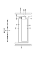
- FIG. 1 is a diagram illustrating a schematic configuration of an image forming apparatus according to a first embodiment of the present disclosure.
- FIG. 4 is a perspective view showing the main body housing with a cover opened.
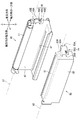
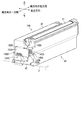
- FIG. 2 is a perspective view illustrating a developing cartridge and a drum cartridge according to the first embodiment.
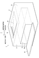
- FIG. 4 is a diagram of the drum cartridge and the developing cartridge mounted in the main body housing according to the first embodiment as viewed from above.
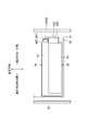
- FIG. 4 is a diagram illustrating a state in which the drum cartridge and the developing cartridge according to the first embodiment are mounted on a main body casing, as viewed from a cover side.
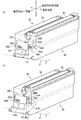
- FIG. 3A is a diagram illustrating a state in which a developing cartridge is pulled out in the first embodiment, and FIG. FIG.
- FIG. 9 is a view of a drum cartridge and a developing cartridge mounted in a main body housing according to a second embodiment as viewed from above.
- FIG. 9 is a diagram illustrating a state in which a drum cartridge and a developing cartridge according to a second embodiment are mounted on a main body casing, as viewed from a cover side.
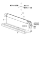
- FIG. 10 is a diagram illustrating a state in which a developing cartridge is pulled out in the second embodiment. It is a perspective view showing a drum cartridge in a 3rd embodiment.
- the image forming apparatus 1 is a color printer.
- the image forming apparatus 1 includes a main body casing 2, a supply unit 3, an image forming unit 4, and a discharge roller 9.
- the supply unit 3 supplies the sheet S to the image forming unit 4.
- the image forming unit 4 forms an image on the sheet S.
- the discharge roller 9 discharges the sheet S.
- the main body casing 2 has a discharge unit 20 at the top.
- the sheet S is discharged to the discharge unit 20.
- the discharge unit 20 is located above an intermediate transfer belt 63 described later.
- the supply unit 3 is located at a lower part in the main body housing 2.
- the supply unit 3 includes a supply tray 31 and a supply mechanism 32.
- the supply tray 31 is detachable from the main housing 2.
- the supply mechanism 32 conveys the sheet S from the supply tray 31 to the image forming unit 4.
- the image forming unit 4 includes a drum cartridge 40, a developing cartridge 50, an exposure device SU, a transfer unit 60, and a fixing unit 70.
- a plurality of drum cartridges 40 and developing cartridges 50 are arranged corresponding to the number of toner colors. In the present embodiment, four drum cartridges 40 and four developing cartridges 50 are arranged side by side.
- Each drum cartridge 40 has a photosensitive drum 41, a frame 42, and a charger (not shown).
- the photoconductor drum 41 is rotatable about a first axis X1 extending in the axial direction.
- the four photosensitive drums 41 are arranged in an orthogonal direction orthogonal to the axial direction and the vertical direction (hereinafter, simply referred to as “orthogonal direction”).
- the frame 42 rotatably supports the photosensitive drum 41.
- Each of the drum cartridges 40 is independently attachable to and detachable from the main housing 2 in the axial direction.
- the frame 42 has a slit 47.
- the slit 47 penetrates the frame 42.
- the laser beam emitted from the exposure device SU which will be described later, is emitted to the surface of the photosensitive drum 41 through the slit 47.
- the drum cartridge 40 is aligned with the developing cartridge 50 in the orthogonal direction.
- Each developing cartridge 50 contains a different color toner.
- Each developing cartridge 50 has a developing roller 51 and a developing case 52.
- the developing roller 51 is rotatable about a second axis X2 extending in the axial direction.
- the developing case 52 contains toner.
- the four developing rollers 51 are arranged in an orthogonal direction.
- the developing cartridges 50 are independently detachable in the axial direction with respect to the main body housing 2.
- the exposure apparatus SU is located below each drum cartridge 40. Exposure device SU emits a laser beam (not shown) to each photosensitive drum 41.
- the transfer unit 60 is located between the four photosensitive drums 41 and the discharge unit 20.
- the transfer unit 60 includes a drive roller 61, a driven roller 62, an intermediate transfer belt 63, four primary transfer rollers 64, and a secondary transfer roller 65.
- the intermediate transfer belt 63 is an endless belt.
- the intermediate transfer belt 63 is located above the drum cartridge 40 and the developing cartridge 50 when the drum cartridge 40 and the developing cartridge 50 are mounted on the main body housing 2.
- the surface of the photosensitive drum 41 contacts the intermediate transfer belt 63 in a state where the drum cartridge 40 and the developing cartridge 50 are mounted on the main body housing 2.
- the intermediate transfer belt 63 is stretched between the driving roller 61 and the driven roller 62.
- the primary transfer roller 64 is located inside the intermediate transfer belt 63.
- the primary transfer roller 64 sandwiches the intermediate transfer belt 63 between the primary transfer roller 64 and the photosensitive drum 41.
- the secondary transfer roller 65 is located outside the intermediate transfer belt 63.
- the secondary transfer roller 65 sandwiches the intermediate transfer belt 63 with the drive roller 61.
- the fixing unit 70 is located above the intermediate transfer belt 63.
- the fixing unit 70 includes a heating roller 71 and a pressure roller 72.
- the pressure roller 72 is pressed by the heating roller 71.
- the image forming unit 4 first, the surface of the photosensitive drum 41 is charged by the charger. After that, the exposure device SU exposes the surface of the photosensitive drum 41 to light. Thus, an electrostatic latent image is formed on the photosensitive drum 41.
- the developing roller 51 supplies toner to the electrostatic latent image on the photosensitive drum 41. As a result, a toner image is formed on the photosensitive drum 41. Then, the toner image on the photosensitive drum 41 is transferred onto the intermediate transfer belt 63.
- the main body casing 2 has a first end face 21, a second end face 22, a slot 23, and a cover 24.
- the first end face 21 is a face located at one end in the axial direction of the main body housing 2.
- the second end surface 22 is a surface located at the other end in the axial direction of the main body housing 2.
- the second end surface 22 is a surface facing the first end surface 21 in the axial direction.
- the slot 23 extends from the first end face 21 to the second end face 22.
- the slots 23 allow the drum cartridge 40 to be attached and detached in the axial direction, and allow the developing cartridge 50 to be attached and detached in the axial direction.
- the slot 23 has an opening 23A for attaching and detaching the drum cartridge 40 and the developing cartridge.
- the cover 24 is a member for opening and closing the opening 23A of the slot 23.
- the drum cartridge 40 has a first handle 43A.
- the first handle 43A is located on the outer surface of the frame 42 in the axial direction.
- the first handle 43A has a rectangular plate shape.
- the first handle 43A is located at a predetermined distance from the outer surface of the frame 42 in the axial direction.
- the drum cartridge 40 further has a first connecting portion 43B.
- the first connecting portion 43B connects the outer surface of the frame 42 in the axial direction and one end of the first handle 43A.
- the first handle 43A has a first opening 45.
- the first opening 45 is an opening located between the outer surface of the frame 42 in the axial direction and the first handle 43A.
- the first opening 45 opens at least on the first axis X1 side in the direction D1 (see FIG. 5) in which the first axis X1 and the second axis X2 are arranged.
- the first openings 45 are opened in three directions.
- the first opening 45 includes a first axis X1 side (first opening 45A) and a second axis X2 side (first opening 45B) in a direction D1 in which the first axis X1 and the second axis X2 are arranged. It opens in three lower directions (first opening 45C).
- the first opening 45 allows a user's finger to be hooked.
- the user can pull out the drum cartridge 40 from the main body housing 2 by putting a finger through the first opening 45 and pulling the first handle 43A.
- the developing cartridge 50 has the second handle 53A.
- the second handle 53A is located on the outer surface of the developing case 52 in the axial direction.
- the second handle 53A has a rectangular plate shape.
- the second handle 53A is located at a predetermined distance from the outer surface of the developing case 52 in the axial direction.
- the developing cartridge 50 further has a second connecting portion 53B.
- the second connecting portion 53B connects the outer surface of the developing case 52 in the axial direction and one end of the second handle 53A.
- the second handle 53A has the second opening 55.
- the second opening 55 is an opening located between the outer surface of the developing case 52 in the axial direction and the second handle 53A.
- the second openings 55 are open in three directions.
- the second opening 55 includes a first axis X1 side (second opening 55A) and a second axis X2 side (second opening 55B) in a direction D1 in which the first axis X1 and the second axis X2 are arranged. It opens in three directions below (second opening 55C).
- the second opening 55 allows a user's finger to be hooked.
- the user can pull out the developing cartridge 50 from the main body casing 2 by putting his / her finger through the second opening 55 and pulling the second handle 53A.
- the first handle 43A and the second handle 53A are exposed from the slot 23 when the drum cartridge 40 and the developing cartridge 50 are mounted on the main body casing 2.
- the second handle 53A is located farther from the second end surface 22 than the first handle 43A in the axial direction.
- At least a part of the first handle 43A and at least a part of the second handle 53A are arranged in the axial direction.
- a part of the first handle 43A and a part of the second handle 53A overlap when viewed from the axial direction.
- the user When removing the developing cartridge 50 from the main body housing 2, the user puts a finger into the second opening 55 and pulls the second handle 53A of the developing cartridge 50 as shown in FIG. Then, the drum cartridge 40 is not taken out, and only the developing cartridge 50 is taken out of the main body casing 2. In this way, when the second handle 53A is pulled out in the axial direction from the main housing 2 in a state where the drum cartridge 40 and the developing cartridge 50 are mounted on the main housing 2, only the developing cartridge 50 is Take out from 2.
- the user When removing the drum cartridge 40 from the main body housing 2, the user puts a finger into the first opening 45 and pulls the first handle 43A of the drum cartridge 40 as shown in FIG. 6B. Then, the first handle 43A comes into contact with the second handle 53A. When the user further pulls the first handle 43A after the first handle 43A contacts the second handle 53A, the first handle 43A pushes the second handle 53A. Pulled out of body 2. In this way, when the first handle 43A is pulled out from the main housing 2 in the axial direction in a state where the drum cartridge 40 and the developing cartridge 50 are mounted on the main housing 2, the first handle 43A is Contact with 53A. When the first handle 43A comes into contact with the second handle 53A, the drum cartridge 40 is pulled out from the main body 2 in the axial direction, and the developing cartridge 50 is also drawn out from the main body 2 in the axial direction.
- the drum cartridge 40 and the developing cartridge 50 are mounted on the main body case 2
- the drum cartridge 40 may be inserted into the main body case 2 first.
- the second handle 53A is more axially than the first handle 43A. It is located far from the second end face 22. For this reason, it is easier to take out the developing cartridge 50 from the main housing 2 than the drum cartridge 40.
- At least a part of the first handle 43A and at least a part of the second handle 53A are arranged in the axial direction.
- the second handle 53 ⁇ / b> A is pulled out of the main housing 2 in the axial direction in a state where the drum cartridge 40 and the developing cartridge 50 are mounted on the main housing 2, only the developing cartridge 50 is removed from the main housing 2. It is.
- the first handle 43A is pulled out from the main body 2 in the axial direction, the first handle 43A comes into contact with the second handle 53A. Therefore, it is possible to prompt the user to take out the developing cartridge 50 before the drum cartridge 40.
- the first handle 43A has a first opening 45 that opens on the first axis X1 side in the direction D1 in which the first axis X1 and the second axis X2 are arranged. For this reason, even when the drum cartridge 40 and the developing cartridge 50 are mounted on the main body housing 2, the developing cartridge 50 does not interfere, and the user can easily catch a finger on the first opening 45.
- the drum cartridge 140 has a first handle 143A.
- the first handle 143A is located at a predetermined distance from the outer surface of the frame 42 in the axial direction.
- the drum cartridge 140 further has a first connecting portion 143B.
- the first connection portion 143B connects the outer surface of the frame 42 in the axial direction and the first handle 143A.
- the first connection portion 143B connects one end of the first handle 143A to the outer surface of the frame 42 in the axial direction.
- the first connecting portion 143B connects the other end of the first handle 143A and the outer surface of the frame 42 in the axial direction.
- the developing cartridge 150 has a second handle 153A.
- the second handle 153A is located at a predetermined distance from the outer surface of the developing case 52 in the axial direction.
- the developing cartridge 150 further has a second connecting portion 153B.
- the second connecting portion 153B connects the outer surface of the developing case 52 in the axial direction and one end of the second handle 153A.
- All of the first handle 143A is axially aligned with at least a part of the second handle 153A. When viewed from the cover 24 side (one end side in the axial direction), all of the first handle 143A overlaps at least a part of the second handle 153A.
- the first handle 143A has the first opening 145.
- the first opening 145 allows a user's finger to be hooked.
- the first opening 145 opens in two directions. Specifically, the first opening 145 is opened on the first axis X1 side (first opening 145A) and the second axis X2 side (first opening 145B) in the direction D1 in which the first axis X1 and the second axis X2 are arranged. doing.
- the user puts a finger through the second opening 155 and pulls the second handle 153A of the developing cartridge 150 as shown in FIG. Then, the drum cartridge 140 is not taken out, and only the developing cartridge 150 is taken out of the main housing 2.
- the first handle 143A has a first opening 145 that opens on the second axis X2 side in the direction D1 in which the first axis X1 and the second axis X2 are aligned. That is, since the first opening 145 is opened on the side of the developing cartridge 150, the user can easily put his / her finger after taking out the developing cartridge 150.
- the drum cartridge 240 has a first handle 243A.
- the first handle 243A is located a predetermined distance away from the outer surface of the frame 42 in the axial direction.
- the drum cartridge 240 further has a first connecting portion 243B.
- the first connecting portion 243B connects the outer surface of the frame 42 in the axial direction and one end of the first handle 243A.
- the first handle 243A has the first opening 245.
- the first opening 245 is located between the outer surface of the frame 42 in the axial direction and the first handle 243A.
- the first opening 245 opens at least upward.
- the first opening 245 does not open downward.
- the first opening 245 opens in three directions.
- the first opening 245 includes a first axis X1 side (first opening 245A) and a second axis X2 side (first opening 245B) in a direction D1 in which the first axis X1 and the second axis X2 are arranged. It opens in three upward directions (first opening 245C).
- the drum cartridge 240 since the first opening 245 opens upward and does not open downward, when the user's finger is hooked on the first handle 243A, the drum cartridge 40 is pushed upward. Can be suppressed. Therefore, contact between the photosensitive drum 41 and the intermediate transfer belt 63 can be suppressed.
- the grips and the connecting portions constituting the first handle and the second handle have rectangular plate shapes.
- each grip portion and each connecting portion need not be rectangular, and the plate shape may be different. It is not necessary.
- the image forming apparatus 1 is a color printer.
- the present invention is not limited to this. May be.
Landscapes
- Physics & Mathematics (AREA)
- General Physics & Mathematics (AREA)
- Electrophotography Configuration And Component (AREA)
Abstract
La présente invention concerne un dispositif de formation d'image qui permet d'extraire une cartouche de développement avant d'extraire une cartouche de tambour. Un dispositif de formation d'image (1) comprend une cartouche de tambour (40), une cartouche de développement (50) et un boîtier de corps (2). La cartouche de tambour 40 comprend un tambour photosensible 41 pouvant tourner autour d'un premier axe X1 qui définit une direction axiale, un cadre 42, et une première poignée 43A. La cartouche de développement 50 comprend un rouleau de développement 51, un boîtier de développement 52 et une seconde poignée 53A. Le boîtier de corps 2 comprend une première face d'extrémité 21 dans la direction axiale, une seconde face d'extrémité 22 faisant face à la première face d'extrémité 21 dans la direction axiale, et une fente 23. La fente 23 permet à la cartouche de tambour 40 et à la cartouche de développement 50 d'être fixées à celle-ci et détachées de celle-ci. La seconde poignée 53A est positionnée plus loin de la seconde face d'extrémité 22 que la première poignée 43A dans la direction axiale, la cartouche de tambour 40 et la cartouche de développement 50 étant montées sur le boîtier de corps 2.
Priority Applications (4)
| Application Number | Priority Date | Filing Date | Title |
|---|---|---|---|
| US16/803,329 US10866557B2 (en) | 2018-09-28 | 2020-02-27 | Image forming apparatus |
| US17/117,419 US11249438B2 (en) | 2018-09-28 | 2020-12-10 | Image forming apparatus |
| US17/591,278 US11740583B2 (en) | 2018-09-28 | 2022-02-02 | Image forming apparatus |
| US18/364,673 US20240027951A1 (en) | 2018-09-28 | 2023-08-03 | Image forming apparatus |
Applications Claiming Priority (2)
| Application Number | Priority Date | Filing Date | Title |
|---|---|---|---|
| JP2018-184040 | 2018-09-28 | ||
| JP2018184040A JP6950655B2 (ja) | 2018-09-28 | 2018-09-28 | 画像形成装置 |
Related Child Applications (1)
| Application Number | Title | Priority Date | Filing Date |
|---|---|---|---|
| US16/803,329 Continuation US10866557B2 (en) | 2018-09-28 | 2020-02-27 | Image forming apparatus |
Publications (1)
| Publication Number | Publication Date |
|---|---|
| WO2020066140A1 true WO2020066140A1 (fr) | 2020-04-02 |
Family
ID=69951847
Family Applications (1)
| Application Number | Title | Priority Date | Filing Date |
|---|---|---|---|
| PCT/JP2019/022497 WO2020066140A1 (fr) | 2018-09-28 | 2019-06-06 | Dispositif de formation d'image |
Country Status (3)
| Country | Link |
|---|---|
| US (4) | US10866557B2 (fr) |
| JP (2) | JP6950655B2 (fr) |
| WO (1) | WO2020066140A1 (fr) |
Citations (5)
| Publication number | Priority date | Publication date | Assignee | Title |
|---|---|---|---|---|
| JP2010102303A (ja) * | 2008-09-29 | 2010-05-06 | Canon Inc | 電子写真画像形成装置 |
| JP2013182103A (ja) * | 2012-03-01 | 2013-09-12 | Sharp Corp | 画像形成装置 |
| JP2013257490A (ja) * | 2012-06-14 | 2013-12-26 | Kyocera Document Solutions Inc | 画像形成装置 |
| US20150139690A1 (en) * | 2013-11-19 | 2015-05-21 | Samsung Electronics Co., Ltd. | Developing device and electrophotographic image forming apparatus having the same |
| JP2018072677A (ja) * | 2016-11-01 | 2018-05-10 | キヤノン株式会社 | 画像形成装置 |
Family Cites Families (9)
| Publication number | Priority date | Publication date | Assignee | Title |
|---|---|---|---|---|
| KR100814425B1 (ko) * | 2003-02-20 | 2008-03-18 | 삼성전자주식회사 | 프로세스 카트리지 및 화상형성장치 |
| JP4664656B2 (ja) * | 2004-11-30 | 2011-04-06 | 京セラミタ株式会社 | 画像形成装置 |
| JP4669358B2 (ja) * | 2005-09-13 | 2011-04-13 | キヤノン株式会社 | 画像形成装置 |
| JP4347331B2 (ja) * | 2005-11-08 | 2009-10-21 | キヤノン株式会社 | 現像剤補給容器 |
| US9104169B2 (en) * | 2013-01-24 | 2015-08-11 | Samsung Electronics Co., Ltd. | Electrophotographic image forming apparatus |
| JP6274162B2 (ja) * | 2015-07-21 | 2018-02-07 | 京セラドキュメントソリューションズ株式会社 | 現像装置及びそれを備えた画像形成装置 |
| JP2018049198A (ja) | 2016-09-23 | 2018-03-29 | キヤノン株式会社 | 画像形成装置及び装置本体 |
| JP7046537B2 (ja) | 2016-11-01 | 2022-04-04 | キヤノン株式会社 | 画像形成装置 |
| US10496034B2 (en) | 2016-11-01 | 2019-12-03 | Canon Kabushiki Kaisha | Image forming apparatus |
-
2018
- 2018-09-28 JP JP2018184040A patent/JP6950655B2/ja active Active
-
2019
- 2019-06-06 WO PCT/JP2019/022497 patent/WO2020066140A1/fr active Application Filing
-
2020
- 2020-02-27 US US16/803,329 patent/US10866557B2/en active Active
- 2020-12-10 US US17/117,419 patent/US11249438B2/en active Active
-
2021
- 2021-09-17 JP JP2021151898A patent/JP7095794B2/ja active Active
-
2022
- 2022-02-02 US US17/591,278 patent/US11740583B2/en active Active
-
2023
- 2023-08-03 US US18/364,673 patent/US20240027951A1/en active Pending
Patent Citations (5)
| Publication number | Priority date | Publication date | Assignee | Title |
|---|---|---|---|---|
| JP2010102303A (ja) * | 2008-09-29 | 2010-05-06 | Canon Inc | 電子写真画像形成装置 |
| JP2013182103A (ja) * | 2012-03-01 | 2013-09-12 | Sharp Corp | 画像形成装置 |
| JP2013257490A (ja) * | 2012-06-14 | 2013-12-26 | Kyocera Document Solutions Inc | 画像形成装置 |
| US20150139690A1 (en) * | 2013-11-19 | 2015-05-21 | Samsung Electronics Co., Ltd. | Developing device and electrophotographic image forming apparatus having the same |
| JP2018072677A (ja) * | 2016-11-01 | 2018-05-10 | キヤノン株式会社 | 画像形成装置 |
Also Published As
| Publication number | Publication date |
|---|---|
| US10866557B2 (en) | 2020-12-15 |
| US20200192274A1 (en) | 2020-06-18 |
| JP7095794B2 (ja) | 2022-07-05 |
| US20220155720A1 (en) | 2022-05-19 |
| US11740583B2 (en) | 2023-08-29 |
| US11249438B2 (en) | 2022-02-15 |
| JP2021192124A (ja) | 2021-12-16 |
| JP6950655B2 (ja) | 2021-10-13 |
| JP2020052332A (ja) | 2020-04-02 |
| US20240027951A1 (en) | 2024-01-25 |
| US20210088962A1 (en) | 2021-03-25 |
Similar Documents
| Publication | Publication Date | Title |
|---|---|---|
| CN107132747B (zh) | 显像装置、处理盒以及图像形成装置 | |
| JP6990822B2 (ja) | 現像装置、プロセスカートリッジおよび画像形成装置 | |
| JP5920070B2 (ja) | 画像形成装置 | |
| JP6833362B2 (ja) | 画像形成装置 | |
| JP2013186336A (ja) | 画像形成装置 | |
| WO2020066140A1 (fr) | Dispositif de formation d'image | |
| JP7168117B2 (ja) | 画像形成装置 | |
| JP7468597B2 (ja) | 画像形成装置 | |
| US9164476B2 (en) | Toner cartridge having structure for minimizing deformation when gripped | |
| JP5610740B2 (ja) | 現像カートリッジ | |
| JP4100698B2 (ja) | 画像形成装置 | |
| JPH07325534A (ja) | プロセスカートリッジおよび画像形成装置 | |
| JP2014102522A (ja) | 画像形成装置 | |
| JP5360433B2 (ja) | 画像形成装置 | |
| JP4569645B2 (ja) | 画像形成装置 | |
| JP2018077321A (ja) | 画像形成装置 | |
| JP6378586B2 (ja) | 機械部品、トナーカートリッジ及び画像形成装置 | |
| JP2005298217A5 (fr) | ||
| JP4440660B2 (ja) | スナップ嵌合機構、プロセスカートリッジおよび画像形成装置 | |
| JP6291980B2 (ja) | 給紙カセット、及び、画像形成装置 | |
| JP2012068671A (ja) | 画像形成装置 | |
| JP2019152840A (ja) | 画像形成装置 | |
| JP2008275929A (ja) | 画像形成装置 | |
| JP2020052356A (ja) | 画像形成装置 | |
| JP2010096794A (ja) | 画像形成装置 |
Legal Events
| Date | Code | Title | Description |
|---|---|---|---|
| 121 | Ep: the epo has been informed by wipo that ep was designated in this application |
Ref document number: 19865192 Country of ref document: EP Kind code of ref document: A1 |
|
| NENP | Non-entry into the national phase |
Ref country code: DE |
|
| 122 | Ep: pct application non-entry in european phase |
Ref document number: 19865192 Country of ref document: EP Kind code of ref document: A1 |