WO2020066140A1 - Image formation device - Google Patents
Image formation device Download PDFInfo
- Publication number
- WO2020066140A1 WO2020066140A1 PCT/JP2019/022497 JP2019022497W WO2020066140A1 WO 2020066140 A1 WO2020066140 A1 WO 2020066140A1 JP 2019022497 W JP2019022497 W JP 2019022497W WO 2020066140 A1 WO2020066140 A1 WO 2020066140A1
- Authority
- WO
- WIPO (PCT)
- Prior art keywords
- handle
- cartridge
- axial direction
- main body
- drum
- Prior art date
Links
Images


Classifications
-
- G—PHYSICS
- G03—PHOTOGRAPHY; CINEMATOGRAPHY; ANALOGOUS TECHNIQUES USING WAVES OTHER THAN OPTICAL WAVES; ELECTROGRAPHY; HOLOGRAPHY
- G03G—ELECTROGRAPHY; ELECTROPHOTOGRAPHY; MAGNETOGRAPHY
- G03G21/00—Arrangements not provided for by groups G03G13/00 - G03G19/00, e.g. cleaning, elimination of residual charge
- G03G21/16—Mechanical means for facilitating the maintenance of the apparatus, e.g. modular arrangements
- G03G21/1642—Mechanical means for facilitating the maintenance of the apparatus, e.g. modular arrangements for connecting the different parts of the apparatus
- G03G21/1647—Mechanical connection means
-
- G—PHYSICS
- G03—PHOTOGRAPHY; CINEMATOGRAPHY; ANALOGOUS TECHNIQUES USING WAVES OTHER THAN OPTICAL WAVES; ELECTROGRAPHY; HOLOGRAPHY
- G03G—ELECTROGRAPHY; ELECTROPHOTOGRAPHY; MAGNETOGRAPHY
- G03G21/00—Arrangements not provided for by groups G03G13/00 - G03G19/00, e.g. cleaning, elimination of residual charge
- G03G21/16—Mechanical means for facilitating the maintenance of the apparatus, e.g. modular arrangements
- G03G21/1661—Mechanical means for facilitating the maintenance of the apparatus, e.g. modular arrangements means for handling parts of the apparatus in the apparatus
- G03G21/1671—Mechanical means for facilitating the maintenance of the apparatus, e.g. modular arrangements means for handling parts of the apparatus in the apparatus for the photosensitive element
-
- G—PHYSICS
- G03—PHOTOGRAPHY; CINEMATOGRAPHY; ANALOGOUS TECHNIQUES USING WAVES OTHER THAN OPTICAL WAVES; ELECTROGRAPHY; HOLOGRAPHY
- G03G—ELECTROGRAPHY; ELECTROPHOTOGRAPHY; MAGNETOGRAPHY
- G03G21/00—Arrangements not provided for by groups G03G13/00 - G03G19/00, e.g. cleaning, elimination of residual charge
- G03G21/16—Mechanical means for facilitating the maintenance of the apparatus, e.g. modular arrangements
- G03G21/1661—Mechanical means for facilitating the maintenance of the apparatus, e.g. modular arrangements means for handling parts of the apparatus in the apparatus
- G03G21/1676—Mechanical means for facilitating the maintenance of the apparatus, e.g. modular arrangements means for handling parts of the apparatus in the apparatus for the developer unit
Definitions
- the present disclosure relates to an image forming apparatus including a detachable drum cartridge and a developing cartridge.
- the drum cartridge and the developing cartridge can be individually attached to and detached from the main body housing in the axial direction, the developing cartridge is more frequently replaced than the drum cartridge. It is required that the developing cartridge which is frequently exchanged can be easily and easily taken out.
- the present disclosure provides an image forming apparatus in which, when the drum cartridge and the developing cartridge are detachable in the axial direction with respect to the main body housing, the developing cartridge can be more easily taken out of the main body housing than the drum cartridge. With the goal.
- an image forming apparatus includes a drum cartridge, a developing cartridge, and a main body housing.
- the drum cartridge includes a photosensitive drum rotatable about a first shaft extending in the axial direction, a frame rotatably supporting the photosensitive drum, and a first handle located on an outer surface of the frame in the axial direction.
- the developing cartridge has a developing roller rotatable about a second shaft extending in the axial direction, a developing housing capable of storing toner, and a second handle located on an outer surface of the developing housing in the axial direction.
- the main body housing has a first end face in the axial direction, a second end face facing the first end face in the axial direction, and a slot.
- the slot extends from the first end face toward the second end face, and allows the drum cartridge to be attached and detached in the axial direction, and allows the developer cartridge to be attached and detached in the axial direction.
- the first handle and the second handle are exposed from the slots.
- the second handle is located farther from the second end face than the first handle in the axial direction.
- the developing cartridge can be more easily taken out of the main body casing than the drum cartridge. Therefore, the developing cartridge that is frequently exchanged can be easily and easily attached and detached.
- At least a part of the first handle and at least a part of the second handle may be arranged in the axial direction.
- the user can be prompted to take out the developing cartridge before the drum cartridge.
- the first handle in a state where the drum cartridge and the developing cartridge are attached to the main body case, when the second handle is pulled out from the main body case in the axial direction, only the developing cartridge is taken out from the main body case, In a state where the drum cartridge and the developing cartridge are mounted on the main body case, when the first handle is pulled out from the main body case in the axial direction, the first handle may be in contact with the second handle.
- the user can be prompted to take out the developing cartridge before the drum cartridge.
- the first handle when the first handle is pulled out of the main body case in the axial direction, the first handle comes into contact with the second handle, and the drum cartridge is drawn out of the main body case in the axial direction.
- the developing cartridge may also be configured to be drawn out of the main body housing in the axial direction.
- both the drum cartridge and the developing cartridge can be pulled out from the main body casing.
- a part of the first handle and a part of the second handle may be arranged in the axial direction.
- the user can be prompted to take out the developing cartridge before the drum cartridge.
- the first handle has a first opening that allows a user's finger to be hooked, and the first opening has at least a first opening in a direction in which the first axis and the second axis are aligned. It may be configured to be open to the shaft side.
- the developing cartridge does not become an obstacle, and the user can easily catch a finger on the first opening.
- all of the first handles may be arranged in at least a part of the second handles in the axial direction.
- the user can be prompted to take out the developing cartridge before the drum cartridge.
- the first handle has a first opening that allows a user's finger to be hooked, and the first opening is on a second axis side in a direction in which the first axis and the second axis are aligned. It may be configured to be open.
- the user can easily put his / her finger into the first opening after taking out the developing cartridge.
- the intermediate transfer belt located above the drum cartridge and the developing cartridge when the drum cartridge and the developing cartridge are mounted on the main body housing, wherein the drum cartridge and the developing cartridge are attached to the main body housing.
- the image forming apparatus may further include an intermediate transfer belt that makes contact with the surface of the photosensitive drum.
- the image forming apparatus may be configured to include a discharge unit that is located above the intermediate transfer belt and discharges the sheet.
- the first handle has a first opening that allows a user's finger to be hooked, and when the drum cartridge is mounted on the main body housing, the first opening is at least upward. It is good also as a structure opened to.
- the first opening is opened upward, it is possible to prevent the drum cartridge from being pushed upward when the user's finger is hooked on the first handle. For this reason, contact of the photosensitive drum with the intermediate transfer belt can be suppressed.
- the first handle has a first opening that allows a user's finger to be hooked, and when the drum cartridge is mounted on the main body case, the first opening is downward. It is good also as a structure which does not open.
- the first opening does not open downward, it is possible to prevent the user from hooking the finger from below the first handle. Therefore, it is possible to prevent the drum cartridge from being pulled out while being pushed upward. For this reason, when taking out a drum cartridge, it can control that a photosensitive drum contacts an intermediate transfer belt.
- the developing cartridge when the drum cartridge and the developing cartridge can be attached to and detached from the main housing in the axial direction, the developing cartridge can be more easily taken out of the main housing than the drum cartridge.
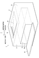
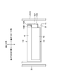
- FIG. 1 is a diagram illustrating a schematic configuration of an image forming apparatus according to a first embodiment of the present disclosure.
- FIG. 4 is a perspective view showing the main body housing with a cover opened.
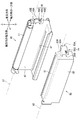
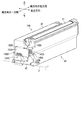
- FIG. 2 is a perspective view illustrating a developing cartridge and a drum cartridge according to the first embodiment.
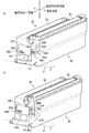
- FIG. 4 is a diagram of the drum cartridge and the developing cartridge mounted in the main body housing according to the first embodiment as viewed from above.
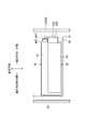
- FIG. 4 is a diagram illustrating a state in which the drum cartridge and the developing cartridge according to the first embodiment are mounted on a main body casing, as viewed from a cover side.
- FIG. 3A is a diagram illustrating a state in which a developing cartridge is pulled out in the first embodiment, and FIG. FIG.
- FIG. 9 is a view of a drum cartridge and a developing cartridge mounted in a main body housing according to a second embodiment as viewed from above.
- FIG. 9 is a diagram illustrating a state in which a drum cartridge and a developing cartridge according to a second embodiment are mounted on a main body casing, as viewed from a cover side.
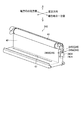
- FIG. 10 is a diagram illustrating a state in which a developing cartridge is pulled out in the second embodiment. It is a perspective view showing a drum cartridge in a 3rd embodiment.
- the image forming apparatus 1 is a color printer.
- the image forming apparatus 1 includes a main body casing 2, a supply unit 3, an image forming unit 4, and a discharge roller 9.
- the supply unit 3 supplies the sheet S to the image forming unit 4.
- the image forming unit 4 forms an image on the sheet S.
- the discharge roller 9 discharges the sheet S.
- the main body casing 2 has a discharge unit 20 at the top.
- the sheet S is discharged to the discharge unit 20.
- the discharge unit 20 is located above an intermediate transfer belt 63 described later.
- the supply unit 3 is located at a lower part in the main body housing 2.
- the supply unit 3 includes a supply tray 31 and a supply mechanism 32.
- the supply tray 31 is detachable from the main housing 2.
- the supply mechanism 32 conveys the sheet S from the supply tray 31 to the image forming unit 4.
- the image forming unit 4 includes a drum cartridge 40, a developing cartridge 50, an exposure device SU, a transfer unit 60, and a fixing unit 70.
- a plurality of drum cartridges 40 and developing cartridges 50 are arranged corresponding to the number of toner colors. In the present embodiment, four drum cartridges 40 and four developing cartridges 50 are arranged side by side.
- Each drum cartridge 40 has a photosensitive drum 41, a frame 42, and a charger (not shown).
- the photoconductor drum 41 is rotatable about a first axis X1 extending in the axial direction.
- the four photosensitive drums 41 are arranged in an orthogonal direction orthogonal to the axial direction and the vertical direction (hereinafter, simply referred to as “orthogonal direction”).
- the frame 42 rotatably supports the photosensitive drum 41.
- Each of the drum cartridges 40 is independently attachable to and detachable from the main housing 2 in the axial direction.
- the frame 42 has a slit 47.
- the slit 47 penetrates the frame 42.
- the laser beam emitted from the exposure device SU which will be described later, is emitted to the surface of the photosensitive drum 41 through the slit 47.
- the drum cartridge 40 is aligned with the developing cartridge 50 in the orthogonal direction.
- Each developing cartridge 50 contains a different color toner.
- Each developing cartridge 50 has a developing roller 51 and a developing case 52.
- the developing roller 51 is rotatable about a second axis X2 extending in the axial direction.
- the developing case 52 contains toner.
- the four developing rollers 51 are arranged in an orthogonal direction.
- the developing cartridges 50 are independently detachable in the axial direction with respect to the main body housing 2.
- the exposure apparatus SU is located below each drum cartridge 40. Exposure device SU emits a laser beam (not shown) to each photosensitive drum 41.
- the transfer unit 60 is located between the four photosensitive drums 41 and the discharge unit 20.
- the transfer unit 60 includes a drive roller 61, a driven roller 62, an intermediate transfer belt 63, four primary transfer rollers 64, and a secondary transfer roller 65.
- the intermediate transfer belt 63 is an endless belt.
- the intermediate transfer belt 63 is located above the drum cartridge 40 and the developing cartridge 50 when the drum cartridge 40 and the developing cartridge 50 are mounted on the main body housing 2.
- the surface of the photosensitive drum 41 contacts the intermediate transfer belt 63 in a state where the drum cartridge 40 and the developing cartridge 50 are mounted on the main body housing 2.
- the intermediate transfer belt 63 is stretched between the driving roller 61 and the driven roller 62.
- the primary transfer roller 64 is located inside the intermediate transfer belt 63.
- the primary transfer roller 64 sandwiches the intermediate transfer belt 63 between the primary transfer roller 64 and the photosensitive drum 41.
- the secondary transfer roller 65 is located outside the intermediate transfer belt 63.
- the secondary transfer roller 65 sandwiches the intermediate transfer belt 63 with the drive roller 61.
- the fixing unit 70 is located above the intermediate transfer belt 63.
- the fixing unit 70 includes a heating roller 71 and a pressure roller 72.
- the pressure roller 72 is pressed by the heating roller 71.
- the image forming unit 4 first, the surface of the photosensitive drum 41 is charged by the charger. After that, the exposure device SU exposes the surface of the photosensitive drum 41 to light. Thus, an electrostatic latent image is formed on the photosensitive drum 41.
- the developing roller 51 supplies toner to the electrostatic latent image on the photosensitive drum 41. As a result, a toner image is formed on the photosensitive drum 41. Then, the toner image on the photosensitive drum 41 is transferred onto the intermediate transfer belt 63.
- the main body casing 2 has a first end face 21, a second end face 22, a slot 23, and a cover 24.
- the first end face 21 is a face located at one end in the axial direction of the main body housing 2.
- the second end surface 22 is a surface located at the other end in the axial direction of the main body housing 2.
- the second end surface 22 is a surface facing the first end surface 21 in the axial direction.
- the slot 23 extends from the first end face 21 to the second end face 22.
- the slots 23 allow the drum cartridge 40 to be attached and detached in the axial direction, and allow the developing cartridge 50 to be attached and detached in the axial direction.
- the slot 23 has an opening 23A for attaching and detaching the drum cartridge 40 and the developing cartridge.
- the cover 24 is a member for opening and closing the opening 23A of the slot 23.
- the drum cartridge 40 has a first handle 43A.
- the first handle 43A is located on the outer surface of the frame 42 in the axial direction.
- the first handle 43A has a rectangular plate shape.
- the first handle 43A is located at a predetermined distance from the outer surface of the frame 42 in the axial direction.
- the drum cartridge 40 further has a first connecting portion 43B.
- the first connecting portion 43B connects the outer surface of the frame 42 in the axial direction and one end of the first handle 43A.
- the first handle 43A has a first opening 45.
- the first opening 45 is an opening located between the outer surface of the frame 42 in the axial direction and the first handle 43A.
- the first opening 45 opens at least on the first axis X1 side in the direction D1 (see FIG. 5) in which the first axis X1 and the second axis X2 are arranged.
- the first openings 45 are opened in three directions.
- the first opening 45 includes a first axis X1 side (first opening 45A) and a second axis X2 side (first opening 45B) in a direction D1 in which the first axis X1 and the second axis X2 are arranged. It opens in three lower directions (first opening 45C).
- the first opening 45 allows a user's finger to be hooked.
- the user can pull out the drum cartridge 40 from the main body housing 2 by putting a finger through the first opening 45 and pulling the first handle 43A.
- the developing cartridge 50 has the second handle 53A.
- the second handle 53A is located on the outer surface of the developing case 52 in the axial direction.
- the second handle 53A has a rectangular plate shape.
- the second handle 53A is located at a predetermined distance from the outer surface of the developing case 52 in the axial direction.
- the developing cartridge 50 further has a second connecting portion 53B.
- the second connecting portion 53B connects the outer surface of the developing case 52 in the axial direction and one end of the second handle 53A.
- the second handle 53A has the second opening 55.
- the second opening 55 is an opening located between the outer surface of the developing case 52 in the axial direction and the second handle 53A.
- the second openings 55 are open in three directions.
- the second opening 55 includes a first axis X1 side (second opening 55A) and a second axis X2 side (second opening 55B) in a direction D1 in which the first axis X1 and the second axis X2 are arranged. It opens in three directions below (second opening 55C).
- the second opening 55 allows a user's finger to be hooked.
- the user can pull out the developing cartridge 50 from the main body casing 2 by putting his / her finger through the second opening 55 and pulling the second handle 53A.
- the first handle 43A and the second handle 53A are exposed from the slot 23 when the drum cartridge 40 and the developing cartridge 50 are mounted on the main body casing 2.
- the second handle 53A is located farther from the second end surface 22 than the first handle 43A in the axial direction.
- At least a part of the first handle 43A and at least a part of the second handle 53A are arranged in the axial direction.
- a part of the first handle 43A and a part of the second handle 53A overlap when viewed from the axial direction.
- the user When removing the developing cartridge 50 from the main body housing 2, the user puts a finger into the second opening 55 and pulls the second handle 53A of the developing cartridge 50 as shown in FIG. Then, the drum cartridge 40 is not taken out, and only the developing cartridge 50 is taken out of the main body casing 2. In this way, when the second handle 53A is pulled out in the axial direction from the main housing 2 in a state where the drum cartridge 40 and the developing cartridge 50 are mounted on the main housing 2, only the developing cartridge 50 is Take out from 2.
- the user When removing the drum cartridge 40 from the main body housing 2, the user puts a finger into the first opening 45 and pulls the first handle 43A of the drum cartridge 40 as shown in FIG. 6B. Then, the first handle 43A comes into contact with the second handle 53A. When the user further pulls the first handle 43A after the first handle 43A contacts the second handle 53A, the first handle 43A pushes the second handle 53A. Pulled out of body 2. In this way, when the first handle 43A is pulled out from the main housing 2 in the axial direction in a state where the drum cartridge 40 and the developing cartridge 50 are mounted on the main housing 2, the first handle 43A is Contact with 53A. When the first handle 43A comes into contact with the second handle 53A, the drum cartridge 40 is pulled out from the main body 2 in the axial direction, and the developing cartridge 50 is also drawn out from the main body 2 in the axial direction.
- the drum cartridge 40 and the developing cartridge 50 are mounted on the main body case 2
- the drum cartridge 40 may be inserted into the main body case 2 first.
- the second handle 53A is more axially than the first handle 43A. It is located far from the second end face 22. For this reason, it is easier to take out the developing cartridge 50 from the main housing 2 than the drum cartridge 40.
- At least a part of the first handle 43A and at least a part of the second handle 53A are arranged in the axial direction.
- the second handle 53 ⁇ / b> A is pulled out of the main housing 2 in the axial direction in a state where the drum cartridge 40 and the developing cartridge 50 are mounted on the main housing 2, only the developing cartridge 50 is removed from the main housing 2. It is.
- the first handle 43A is pulled out from the main body 2 in the axial direction, the first handle 43A comes into contact with the second handle 53A. Therefore, it is possible to prompt the user to take out the developing cartridge 50 before the drum cartridge 40.
- the first handle 43A has a first opening 45 that opens on the first axis X1 side in the direction D1 in which the first axis X1 and the second axis X2 are arranged. For this reason, even when the drum cartridge 40 and the developing cartridge 50 are mounted on the main body housing 2, the developing cartridge 50 does not interfere, and the user can easily catch a finger on the first opening 45.
- the drum cartridge 140 has a first handle 143A.
- the first handle 143A is located at a predetermined distance from the outer surface of the frame 42 in the axial direction.
- the drum cartridge 140 further has a first connecting portion 143B.
- the first connection portion 143B connects the outer surface of the frame 42 in the axial direction and the first handle 143A.
- the first connection portion 143B connects one end of the first handle 143A to the outer surface of the frame 42 in the axial direction.
- the first connecting portion 143B connects the other end of the first handle 143A and the outer surface of the frame 42 in the axial direction.
- the developing cartridge 150 has a second handle 153A.
- the second handle 153A is located at a predetermined distance from the outer surface of the developing case 52 in the axial direction.
- the developing cartridge 150 further has a second connecting portion 153B.
- the second connecting portion 153B connects the outer surface of the developing case 52 in the axial direction and one end of the second handle 153A.
- All of the first handle 143A is axially aligned with at least a part of the second handle 153A. When viewed from the cover 24 side (one end side in the axial direction), all of the first handle 143A overlaps at least a part of the second handle 153A.
- the first handle 143A has the first opening 145.
- the first opening 145 allows a user's finger to be hooked.
- the first opening 145 opens in two directions. Specifically, the first opening 145 is opened on the first axis X1 side (first opening 145A) and the second axis X2 side (first opening 145B) in the direction D1 in which the first axis X1 and the second axis X2 are arranged. doing.
- the user puts a finger through the second opening 155 and pulls the second handle 153A of the developing cartridge 150 as shown in FIG. Then, the drum cartridge 140 is not taken out, and only the developing cartridge 150 is taken out of the main housing 2.
- the first handle 143A has a first opening 145 that opens on the second axis X2 side in the direction D1 in which the first axis X1 and the second axis X2 are aligned. That is, since the first opening 145 is opened on the side of the developing cartridge 150, the user can easily put his / her finger after taking out the developing cartridge 150.
- the drum cartridge 240 has a first handle 243A.
- the first handle 243A is located a predetermined distance away from the outer surface of the frame 42 in the axial direction.
- the drum cartridge 240 further has a first connecting portion 243B.
- the first connecting portion 243B connects the outer surface of the frame 42 in the axial direction and one end of the first handle 243A.
- the first handle 243A has the first opening 245.
- the first opening 245 is located between the outer surface of the frame 42 in the axial direction and the first handle 243A.
- the first opening 245 opens at least upward.
- the first opening 245 does not open downward.
- the first opening 245 opens in three directions.
- the first opening 245 includes a first axis X1 side (first opening 245A) and a second axis X2 side (first opening 245B) in a direction D1 in which the first axis X1 and the second axis X2 are arranged. It opens in three upward directions (first opening 245C).
- the drum cartridge 240 since the first opening 245 opens upward and does not open downward, when the user's finger is hooked on the first handle 243A, the drum cartridge 40 is pushed upward. Can be suppressed. Therefore, contact between the photosensitive drum 41 and the intermediate transfer belt 63 can be suppressed.
- the grips and the connecting portions constituting the first handle and the second handle have rectangular plate shapes.
- each grip portion and each connecting portion need not be rectangular, and the plate shape may be different. It is not necessary.
- the image forming apparatus 1 is a color printer.
- the present invention is not limited to this. May be.
Abstract
The present invention provides an image formation device that allows for extracting a development cartridge before extracting a drum cartridge. An image formation device 1 includes a drum cartridge 40, a development cartridge 50, and a body housing 2. The drum cartridge 40 includes a photosensitive drum 41 rotatable about a first axis X1 which defines an axial direction, a frame 42, and a first handle 43A. The development cartridge 50 includes a development roller 51, a development housing 52, and a second handle 53A. The body housing 2 includes a first end face 21 in the axial direction, a second end face 22 facing the first end face 21 in the axial direction, and a slot 23. The slot 23 allows the drum cartridge 40 and the development cartridge 50 to be attached thereto and detached therefrom. The second handle 53A is positioned further away from the second end face 22 than the first handle 43A in the axial direction with the drum cartridge 40 and the development cartridge 50 mounted on the body housing 2.
Description
本開示は、着脱可能なドラムカートリッジおよび現像カートリッジを備える画像形成装置に関する。
The present disclosure relates to an image forming apparatus including a detachable drum cartridge and a developing cartridge.
従来、本体筐体に対してドラムカートリッジおよび現像カートリッジを、感光体ドラムの回転軸に沿った方向である軸方向に着脱可能な画像形成装置が知られている(特許文献1参照)。この技術では、ドラムカートリッジおよび現像カートリッジは、それぞれ本体筐体に対して個別に着脱可能となっている。各カートリッジの軸方向端部の側面には、使用者によって掴むことが可能なハンドルが設けられている。使用者は、ハンドルを指で挟持して各カートリッジを引き出すことが可能となっている。
Conventionally, there has been known an image forming apparatus in which a drum cartridge and a developing cartridge can be attached to and detached from a main body housing in an axial direction which is a direction along a rotation axis of a photosensitive drum (see Patent Document 1). In this technique, the drum cartridge and the developing cartridge are individually detachable from the main body housing. A handle that can be gripped by a user is provided on the side surface of the axial end of each cartridge. The user can pull out each cartridge while holding the handle between fingers.
ところで、ドラムカートリッジおよび現像カートリッジが、本体筐体に対して軸方向に個別に着脱可能な場合、現像カートリッジは、ドラムカートリッジに比べて交換頻度が高い。交換頻度の高い現像カートリッジは、簡易かつ容易に取り出せることが求められる。
By the way, when the drum cartridge and the developing cartridge can be individually attached to and detached from the main body housing in the axial direction, the developing cartridge is more frequently replaced than the drum cartridge. It is required that the developing cartridge which is frequently exchanged can be easily and easily taken out.
そこで、本開示は、ドラムカートリッジおよび現像カートリッジが、本体筐体に対して軸方向に着脱可能な場合に、本体筐体からドラムカートリッジよりも現像カートリッジを先に取り出しやすい画像形成装置を提供することを目的とする。
Therefore, the present disclosure provides an image forming apparatus in which, when the drum cartridge and the developing cartridge are detachable in the axial direction with respect to the main body housing, the developing cartridge can be more easily taken out of the main body housing than the drum cartridge. With the goal.
上述の課題を解決するため、本発明に係る画像形成装置は、ドラムカートリッジと、現像カートリッジと、本体筐体と、を備える。ドラムカートリッジは、軸方向に延びる第1軸について回転可能な感光体ドラムと、感光体ドラムを回転可能に支持するフレームと、軸方向におけるフレームの外表面に位置する第1ハンドルと、を有する。現像カートリッジは、軸方向に延びる第2軸について回転可能な現像ローラと、トナーを収容可能な現像筐体と、軸方向における現像筐体の外表面に位置する第2ハンドルと、を有する。本体筐体は、軸方向における第1端面と、軸方向において第1端面と向かい合う第2端面と、スロットを有する。スロットは、第1端面から第2端面に向けて延び、軸方向にドラムカートリッジが着脱されることを許容し、且つ、軸方向に現像カートリッジが着脱されることを許容する。ドラムカートリッジおよび現像カートリッジが本体筐体に装着された状態において、第1ハンドルと第2ハンドルは、スロットから露出される。ドラムカートリッジおよび現像カートリッジが本体筐体に装着された状態において、第2ハンドルは、軸方向において、第1ハンドルよりも第2端面から遠くに位置する。
In order to solve the above problems, an image forming apparatus according to the present invention includes a drum cartridge, a developing cartridge, and a main body housing. The drum cartridge includes a photosensitive drum rotatable about a first shaft extending in the axial direction, a frame rotatably supporting the photosensitive drum, and a first handle located on an outer surface of the frame in the axial direction. The developing cartridge has a developing roller rotatable about a second shaft extending in the axial direction, a developing housing capable of storing toner, and a second handle located on an outer surface of the developing housing in the axial direction. The main body housing has a first end face in the axial direction, a second end face facing the first end face in the axial direction, and a slot. The slot extends from the first end face toward the second end face, and allows the drum cartridge to be attached and detached in the axial direction, and allows the developer cartridge to be attached and detached in the axial direction. When the drum cartridge and the developing cartridge are mounted on the main body case, the first handle and the second handle are exposed from the slots. In a state where the drum cartridge and the developing cartridge are mounted on the main body case, the second handle is located farther from the second end face than the first handle in the axial direction.
この構成によれば、本体筐体からドラムカートリッジよりも現像カートリッジを先に取り出しやすい。このため、交換頻度の高い現像カートリッジは、簡易かつ容易に着脱できる。
According to this configuration, the developing cartridge can be more easily taken out of the main body casing than the drum cartridge. Therefore, the developing cartridge that is frequently exchanged can be easily and easily attached and detached.
前記した画像形成装置において、第1ハンドルの少なくとも一部と、第2ハンドルの少なくとも一部とは、軸方向に並んでいる構成としてもよい。
In the above-described image forming apparatus, at least a part of the first handle and at least a part of the second handle may be arranged in the axial direction.
これによれば、現像カートリッジを、ドラムカートリッジよりに先に取り出すことを使用者に促すことができる。
According to this, the user can be prompted to take out the developing cartridge before the drum cartridge.
前記した画像形成装置において、ドラムカートリッジおよび現像カートリッジが本体筐体に装着された状態において、第2ハンドルが、本体筐体から軸方向に引き出される場合、現像カートリッジのみが本体筐体から取り出され、ドラムカートリッジおよび現像カートリッジが本体筐体に装着された状態において、第1ハンドルが、本体筐体から軸方向に引き出される場合、第1ハンドルが第2ハンドルと接触する構成としてもよい。
In the above-described image forming apparatus, in a state where the drum cartridge and the developing cartridge are attached to the main body case, when the second handle is pulled out from the main body case in the axial direction, only the developing cartridge is taken out from the main body case, In a state where the drum cartridge and the developing cartridge are mounted on the main body case, when the first handle is pulled out from the main body case in the axial direction, the first handle may be in contact with the second handle.
これによれば、現像カートリッジを、ドラムカートリッジよりに先に取り出すことを使用者に促すことができる。
According to this, the user can be prompted to take out the developing cartridge before the drum cartridge.
前記した画像形成装置において、第1ハンドルが、本体筐体から軸方向に引き出される場合、第1ハンドルが第2ハンドルと接触して、ドラムカートリッジが、本体筐体から軸方向に引き出されると共に、現像カートリッジも本体筐体から軸方向に引き出される構成としてもよい。
In the above-described image forming apparatus, when the first handle is pulled out of the main body case in the axial direction, the first handle comes into contact with the second handle, and the drum cartridge is drawn out of the main body case in the axial direction. The developing cartridge may also be configured to be drawn out of the main body housing in the axial direction.
これによれば、第1ハンドルを引き出せば、ドラムカートリッジと現像カートリッジを両方とも本体筐体から引き出すことができる。
According to this, by pulling out the first handle, both the drum cartridge and the developing cartridge can be pulled out from the main body casing.
前記した画像形成装置において、第1ハンドルの一部と、第2ハンドルの一部とは、軸方向に並んでいる構成としてもよい。
In the image forming apparatus described above, a part of the first handle and a part of the second handle may be arranged in the axial direction.
これによれば、現像カートリッジを、ドラムカートリッジよりに先に取り出すことを使用者に促すことができる。
According to this, the user can be prompted to take out the developing cartridge before the drum cartridge.
前記した画像形成装置において、第1ハンドルは、使用者の指が引っかけられることを許容する第1開口を有し、第1開口は、少なくとも、第1軸と第2軸が並ぶ方向の第1軸側に開口している構成としてもよい。
In the above-described image forming apparatus, the first handle has a first opening that allows a user's finger to be hooked, and the first opening has at least a first opening in a direction in which the first axis and the second axis are aligned. It may be configured to be open to the shaft side.
これによれば、ドラムカートリッジおよび現像カートリッジが本体筐体に装着されている状態であっても、現像カートリッジが邪魔にならず、使用者は、第1開口に指をひっかけやすい。
According to this, even when the drum cartridge and the developing cartridge are mounted on the main body case, the developing cartridge does not become an obstacle, and the user can easily catch a finger on the first opening.
前記した画像形成装置において、第1ハンドルの全ては、第2ハンドルの少なくとも一部と、軸方向に並んでいる構成としてもよい。
In the image forming apparatus described above, all of the first handles may be arranged in at least a part of the second handles in the axial direction.
これによれば、現像カートリッジを、ドラムカートリッジよりに先に取り出すことを使用者に促すことができる。
According to this, the user can be prompted to take out the developing cartridge before the drum cartridge.
前記画像形成装置において、第1ハンドルは、使用者の指が引っかけられることを許容する第1開口を有し、第1開口は、第1軸と第2軸が並ぶ方向の第2軸側に開口している構成としてもよい。
In the image forming apparatus, the first handle has a first opening that allows a user's finger to be hooked, and the first opening is on a second axis side in a direction in which the first axis and the second axis are aligned. It may be configured to be open.
これによれば、第1ハンドルの第1開口が現像カートリッジ側に開口しているので、現像カートリッジを取り出した後は、ユーザは第1開口に指を入れやすい。
According to this, since the first opening of the first handle is open toward the developing cartridge, the user can easily put his / her finger into the first opening after taking out the developing cartridge.
前記した画像形成装置において、ドラムカートリッジおよび現像カートリッジが本体筐体に装着された状態において、ドラムカートリッジおよび現像カートリッジの上方に位置する中間転写ベルトであって、ドラムカートリッジおよび現像カートリッジが本体筐体に装着された状態において、感光体ドラムの表面が接触する中間転写ベルトをさらに備える構成としてもよい。
In the above-described image forming apparatus, the intermediate transfer belt located above the drum cartridge and the developing cartridge when the drum cartridge and the developing cartridge are mounted on the main body housing, wherein the drum cartridge and the developing cartridge are attached to the main body housing. In the mounted state, the image forming apparatus may further include an intermediate transfer belt that makes contact with the surface of the photosensitive drum.
前記した画像形成装置において、中間転写ベルトの上方に位置し、シートが排出される排出部を備える構成としてもよい。
In the above-described image forming apparatus, the image forming apparatus may be configured to include a discharge unit that is located above the intermediate transfer belt and discharges the sheet.
前記した画像形成装置において、第1ハンドルは、使用者の指が引っかけられることを許容する第1開口を有し、ドラムカートリッジが本体筐体に装着された状態において、第1開口は、少なくとも上方に開口している構成としてもよい。
In the above-described image forming apparatus, the first handle has a first opening that allows a user's finger to be hooked, and when the drum cartridge is mounted on the main body housing, the first opening is at least upward. It is good also as a structure opened to.
これによれば、第1開口が上方に開口しているので、使用者の指が第1ハンドルに引っかけられた場合に、ドラムカートリッジが上方へ押されてしまうことを抑制することができる。このため、感光体ドラムが中間転写ベルトに接触することを抑制することができる。
According to this, since the first opening is opened upward, it is possible to prevent the drum cartridge from being pushed upward when the user's finger is hooked on the first handle. For this reason, contact of the photosensitive drum with the intermediate transfer belt can be suppressed.
前記した画像形成装置において、第1ハンドルは、使用者の指が引っかけられることを許容する第1開口を有し、ドラムカートリッジが本体筐体に装着された状態において、第1開口は、下方に開口していない構成としてもよい。
In the above-described image forming apparatus, the first handle has a first opening that allows a user's finger to be hooked, and when the drum cartridge is mounted on the main body case, the first opening is downward. It is good also as a structure which does not open.
これによれば、第1開口が下方に開口していないので、使用者が指を第1ハンドルの下方から引っ掛けることを抑制することができる。このため、ドラムカートリッジが上方へ押されながら引き出されることを抑制することができる。このため、ドラムカートリッジを取り出すときに、感光体ドラムが中間転写ベルトに接触することを抑制することができる。
According to this, since the first opening does not open downward, it is possible to prevent the user from hooking the finger from below the first handle. Therefore, it is possible to prevent the drum cartridge from being pulled out while being pushed upward. For this reason, when taking out a drum cartridge, it can control that a photosensitive drum contacts an intermediate transfer belt.
本開示によれば、ドラムカートリッジおよび現像カートリッジが、本体筐体に対して軸方向に着脱可能な場合、本体筐体からドラムカートリッジよりも現像カートリッジを先に取り出しやすい。
According to the present disclosure, when the drum cartridge and the developing cartridge can be attached to and detached from the main housing in the axial direction, the developing cartridge can be more easily taken out of the main housing than the drum cartridge.
次に、本発明の第1実施形態について、適宜図面を参照しながら詳細に説明する。
図1に示すように、画像形成装置1は、カラープリンタである。画像形成装置1は、本体筐体2と、供給部3と、画像形成部4と、排出ローラ9と、を備える。供給部3は、画像形成部4にシートSを供給する。画像形成部4は、シートSに画像を形成する。排出ローラ9は、シートSを排出する。 Next, a first embodiment of the present invention will be described in detail with reference to the drawings as appropriate.
As shown in FIG. 1, theimage forming apparatus 1 is a color printer. The image forming apparatus 1 includes a main body casing 2, a supply unit 3, an image forming unit 4, and a discharge roller 9. The supply unit 3 supplies the sheet S to the image forming unit 4. The image forming unit 4 forms an image on the sheet S. The discharge roller 9 discharges the sheet S.
図1に示すように、画像形成装置1は、カラープリンタである。画像形成装置1は、本体筐体2と、供給部3と、画像形成部4と、排出ローラ9と、を備える。供給部3は、画像形成部4にシートSを供給する。画像形成部4は、シートSに画像を形成する。排出ローラ9は、シートSを排出する。 Next, a first embodiment of the present invention will be described in detail with reference to the drawings as appropriate.
As shown in FIG. 1, the
本体筐体2は、上部に排出部20を有する。シートSは、排出部20に排出される。排出部20は、後述する中間転写ベルト63の上方に位置する。
The main body casing 2 has a discharge unit 20 at the top. The sheet S is discharged to the discharge unit 20. The discharge unit 20 is located above an intermediate transfer belt 63 described later.
供給部3は、本体筐体2内の下部に位置する。供給部3は、供給トレイ31と、供給機構32と、を備える。供給トレイ31は、本体筐体2に着脱可能である。供給機構32は、シートSを供給トレイ31から画像形成部4に搬送する。
The supply unit 3 is located at a lower part in the main body housing 2. The supply unit 3 includes a supply tray 31 and a supply mechanism 32. The supply tray 31 is detachable from the main housing 2. The supply mechanism 32 conveys the sheet S from the supply tray 31 to the image forming unit 4.
画像形成部4は、ドラムカートリッジ40と、現像カートリッジ50と、露光装置SUと、転写ユニット60と、定着ユニット70と、を備える。ドラムカートリッジ40および現像カートリッジ50は、トナーの色の数に対応して複数配置されている。本実施形態では、ドラムカートリッジ40および現像カートリッジ50は、4つ並んで配置されている。
The image forming unit 4 includes a drum cartridge 40, a developing cartridge 50, an exposure device SU, a transfer unit 60, and a fixing unit 70. A plurality of drum cartridges 40 and developing cartridges 50 are arranged corresponding to the number of toner colors. In the present embodiment, four drum cartridges 40 and four developing cartridges 50 are arranged side by side.
各ドラムカートリッジ40は、感光体ドラム41と、フレーム42と、図示せぬ帯電器と、を有する。感光体ドラム41は、軸方向に延びる第1軸X1について回転可能である。4つの感光体ドラム41は、軸方向および上下方向に直交する直交方向(以下の説明では単に「直交方向」という。)に並んでいる。フレーム42は、感光体ドラム41を回転可能に支持している。各ドラムカートリッジ40は、それぞれ独立して、本体筐体2に対して軸方向に着脱可能となっている。また、図3に示すように、フレーム42は、スリット47を有する。スリット47は、フレーム42を貫通する。なお、後述する露光装置SUから出射されたレーザ光が、スリット47を通って、感光体ドラム41の表面に出射される。
Each drum cartridge 40 has a photosensitive drum 41, a frame 42, and a charger (not shown). The photoconductor drum 41 is rotatable about a first axis X1 extending in the axial direction. The four photosensitive drums 41 are arranged in an orthogonal direction orthogonal to the axial direction and the vertical direction (hereinafter, simply referred to as “orthogonal direction”). The frame 42 rotatably supports the photosensitive drum 41. Each of the drum cartridges 40 is independently attachable to and detachable from the main housing 2 in the axial direction. Further, as shown in FIG. 3, the frame 42 has a slit 47. The slit 47 penetrates the frame 42. The laser beam emitted from the exposure device SU, which will be described later, is emitted to the surface of the photosensitive drum 41 through the slit 47.
図1に戻り、ドラムカートリッジ40および現像カートリッジ50が本体筐体2に装着された状態において、ドラムカートリッジ40は、直交方向において、現像カートリッジ50と並んでいる。
Returning to FIG. 1, in a state where the drum cartridge 40 and the developing cartridge 50 are mounted on the main body housing 2, the drum cartridge 40 is aligned with the developing cartridge 50 in the orthogonal direction.
各現像カートリッジ50は、それぞれ異なる色のトナーを収容している。各現像カートリッジ50は、現像ローラ51と、現像筐体52と、を有している。現像ローラ51は、軸方向に延びる第2軸X2について回転可能である。現像筐体52は、トナーを収容している。4つの現像ローラ51は、直交方向に並んでいる。現像カートリッジ50は、それぞれ独立して、本体筐体2に対して軸方向に着脱可能となっている。
現 像 Each developing cartridge 50 contains a different color toner. Each developing cartridge 50 has a developing roller 51 and a developing case 52. The developing roller 51 is rotatable about a second axis X2 extending in the axial direction. The developing case 52 contains toner. The four developing rollers 51 are arranged in an orthogonal direction. The developing cartridges 50 are independently detachable in the axial direction with respect to the main body housing 2.
露光装置SUは、各ドラムカートリッジ40の下に位置する。露光装置SUは、図示せぬレーザ光を各感光体ドラム41に出射する。
The exposure apparatus SU is located below each drum cartridge 40. Exposure device SU emits a laser beam (not shown) to each photosensitive drum 41.
転写ユニット60は、4つの感光体ドラム41と排出部20との間に位置する。転写ユニット60は、駆動ローラ61と、従動ローラ62と、中間転写ベルト63と、4つの1次転写ローラ64と、2次転写ローラ65と、を備える。
(4) The transfer unit 60 is located between the four photosensitive drums 41 and the discharge unit 20. The transfer unit 60 includes a drive roller 61, a driven roller 62, an intermediate transfer belt 63, four primary transfer rollers 64, and a secondary transfer roller 65.
中間転写ベルト63は、無端状のベルトである。中間転写ベルト63は、ドラムカートリッジ40および現像カートリッジ50が本体筐体2に装着された状態において、ドラムカートリッジ40および現像カートリッジ50の上方に位置する。中間転写ベルト63は、ドラムカートリッジ40および現像カートリッジ50が本体筐体2に装着された状態において、感光体ドラム41の表面が接触する。中間転写ベルト63は、駆動ローラ61および従動ローラ62の間に張設されている。
The intermediate transfer belt 63 is an endless belt. The intermediate transfer belt 63 is located above the drum cartridge 40 and the developing cartridge 50 when the drum cartridge 40 and the developing cartridge 50 are mounted on the main body housing 2. The surface of the photosensitive drum 41 contacts the intermediate transfer belt 63 in a state where the drum cartridge 40 and the developing cartridge 50 are mounted on the main body housing 2. The intermediate transfer belt 63 is stretched between the driving roller 61 and the driven roller 62.
1次転写ローラ64は、中間転写ベルト63の内側に位置する。1次転写ローラ64は、感光体ドラム41との間で中間転写ベルト63を挟む。
(5) The primary transfer roller 64 is located inside the intermediate transfer belt 63. The primary transfer roller 64 sandwiches the intermediate transfer belt 63 between the primary transfer roller 64 and the photosensitive drum 41.
2次転写ローラ65は、中間転写ベルト63の外側に位置する。2次転写ローラ65は、駆動ローラ61との間で中間転写ベルト63を挟む。
(4) The secondary transfer roller 65 is located outside the intermediate transfer belt 63. The secondary transfer roller 65 sandwiches the intermediate transfer belt 63 with the drive roller 61.
定着ユニット70は、中間転写ベルト63の上方に位置する。定着ユニット70は、加熱ローラ71と、加圧ローラ72と、を備える。加圧ローラ72は、加熱ローラ71に押圧される。
The fixing unit 70 is located above the intermediate transfer belt 63. The fixing unit 70 includes a heating roller 71 and a pressure roller 72. The pressure roller 72 is pressed by the heating roller 71.
画像形成部4では、まず、感光体ドラム41の表面が、帯電器で帯電される。その後、露光装置SUが、感光体ドラム41の表面を露光する。これにより、感光体ドラム41上に静電潜像が形成される。
In the image forming unit 4, first, the surface of the photosensitive drum 41 is charged by the charger. After that, the exposure device SU exposes the surface of the photosensitive drum 41 to light. Thus, an electrostatic latent image is formed on the photosensitive drum 41.
次いで、現像ローラ51が、感光体ドラム41上の静電潜像にトナーを供給する。これにより、感光体ドラム41上にトナー像が形成される。そして、感光体ドラム41上のトナー像は、中間転写ベルト63上に転写される。
Next, the developing roller 51 supplies toner to the electrostatic latent image on the photosensitive drum 41. As a result, a toner image is formed on the photosensitive drum 41. Then, the toner image on the photosensitive drum 41 is transferred onto the intermediate transfer belt 63.
シートSが中間転写ベルト63と2次転写ローラ65の間を通過するときに、中間転写ベルト63上のトナー像は、シートS上に転写される。その後、シートS上のトナー像は、定着ユニット70で定着される。次いで、シートSは、排出ローラ9によって排出部20に排出される。
(4) When the sheet S passes between the intermediate transfer belt 63 and the secondary transfer roller 65, the toner image on the intermediate transfer belt 63 is transferred onto the sheet S. After that, the toner image on the sheet S is fixed by the fixing unit 70. Next, the sheet S is discharged to the discharge unit 20 by the discharge roller 9.
図2に示すように、本体筐体2は、第1端面21と、第2端面22と、スロット23と、カバー24と、を有している。
本体 As shown in FIG. 2, the main body casing 2 has a first end face 21, a second end face 22, a slot 23, and a cover 24.
第1端面21は、本体筐体2の軸方向における一方側の端部に位置する面である。第2端面22は、本体筐体2の軸方向における他方側の端部に位置する面である。第2端面22は、軸方向において第1端面21と向かい合う面である。
The first end face 21 is a face located at one end in the axial direction of the main body housing 2. The second end surface 22 is a surface located at the other end in the axial direction of the main body housing 2. The second end surface 22 is a surface facing the first end surface 21 in the axial direction.
スロット23は、第1端面21から第2端面22に向けて延びている。スロット23は、軸方向にドラムカートリッジ40が着脱されることを許容し、且つ、軸方向に現像カートリッジ50が着脱されることを許容する。スロット23は、ドラムカートリッジ40および現像カートリッジを着脱するための開口23Aを有している。
The slot 23 extends from the first end face 21 to the second end face 22. The slots 23 allow the drum cartridge 40 to be attached and detached in the axial direction, and allow the developing cartridge 50 to be attached and detached in the axial direction. The slot 23 has an opening 23A for attaching and detaching the drum cartridge 40 and the developing cartridge.
カバー24は、スロット23の開口23Aを開閉するための部材である。
The cover 24 is a member for opening and closing the opening 23A of the slot 23.
図3に示すように、ドラムカートリッジ40は、第1ハンドル43Aを有している。第1ハンドル43Aは、軸方向におけるフレーム42の外表面に位置している。第1ハンドル43Aは、矩形の板形状を有している。第1ハンドル43Aは、フレーム42の軸方向における外表面から、所定距離離れて位置している。なお、ドラムカートリッジ40は、さらに、第1連結部43Bを有する。第1連結部43Bは、フレーム42の軸方向における外表面と第1ハンドル43Aの一端部とを連結している。
ド ラ ム As shown in FIG. 3, the drum cartridge 40 has a first handle 43A. The first handle 43A is located on the outer surface of the frame 42 in the axial direction. The first handle 43A has a rectangular plate shape. The first handle 43A is located at a predetermined distance from the outer surface of the frame 42 in the axial direction. The drum cartridge 40 further has a first connecting portion 43B. The first connecting portion 43B connects the outer surface of the frame 42 in the axial direction and one end of the first handle 43A.
第1ハンドル43Aは、第1開口45を有している。第1開口45は、フレーム42の軸方向における外表面と第1ハンドル43Aとの間に位置する開口である。第1開口45は、少なくとも、第1軸X1と第2軸X2が並ぶ方向D1(図5参照)の第1軸X1側に開口している。本実施形態では、第1開口45は、3つの方向に開口している。具体的には、第1開口45は、第1軸X1と第2軸X2が並ぶ方向D1の第1軸X1側(第1開口45A)および第2軸X2側(第1開口45B)と、下方の3つの方向(第1開口45C)に開口している。
The first handle 43A has a first opening 45. The first opening 45 is an opening located between the outer surface of the frame 42 in the axial direction and the first handle 43A. The first opening 45 opens at least on the first axis X1 side in the direction D1 (see FIG. 5) in which the first axis X1 and the second axis X2 are arranged. In the present embodiment, the first openings 45 are opened in three directions. Specifically, the first opening 45 includes a first axis X1 side (first opening 45A) and a second axis X2 side (first opening 45B) in a direction D1 in which the first axis X1 and the second axis X2 are arranged. It opens in three lower directions (first opening 45C).
第1開口45は、使用者の指が引っかけられることを許容する。使用者は、第1開口45から指を入れて、第1ハンドル43Aを引っ張ることで、ドラムカートリッジ40を本体筐体2から引き出すことができるようになっている。
The first opening 45 allows a user's finger to be hooked. The user can pull out the drum cartridge 40 from the main body housing 2 by putting a finger through the first opening 45 and pulling the first handle 43A.
現像カートリッジ50は、第2ハンドル53Aを有している。第2ハンドル53Aは、軸方向における現像筐体52の外表面に位置している。第2ハンドル53Aは、矩形の板形状を有している。第2ハンドル53Aは、現像筐体52の軸方向における外表面から所定距離離れて位置している。なお、現像カートリッジ50は、さらに、第2連結部53Bを有する。第2連結部53Bは、現像筐体52の軸方向における外表面と第2ハンドル53Aの一端部とを連結している。
The developing cartridge 50 has the second handle 53A. The second handle 53A is located on the outer surface of the developing case 52 in the axial direction. The second handle 53A has a rectangular plate shape. The second handle 53A is located at a predetermined distance from the outer surface of the developing case 52 in the axial direction. The developing cartridge 50 further has a second connecting portion 53B. The second connecting portion 53B connects the outer surface of the developing case 52 in the axial direction and one end of the second handle 53A.
第2ハンドル53Aは、第2開口55を有している。第2開口55は、現像筐体52の軸方向における外表面と第2ハンドル53Aとの間に位置する開口である。本実施形態では、第2開口55は、3つの方向に開口している。具体的には、第2開口55は、第1軸X1と第2軸X2が並ぶ方向D1の第1軸X1側(第2開口55A)および第2軸X2側(第2開口55B)と、下方(第2開口55C)の3つの方向に開口している。
The second handle 53A has the second opening 55. The second opening 55 is an opening located between the outer surface of the developing case 52 in the axial direction and the second handle 53A. In the present embodiment, the second openings 55 are open in three directions. Specifically, the second opening 55 includes a first axis X1 side (second opening 55A) and a second axis X2 side (second opening 55B) in a direction D1 in which the first axis X1 and the second axis X2 are arranged. It opens in three directions below (second opening 55C).
第2開口55は、使用者の指が引っかけられることを許容する。使用者は、第2開口55から指を入れて、第2ハンドル53Aを引っ張ることで、現像カートリッジ50を本体筐体2から引き出すことができるようになっている。
The second opening 55 allows a user's finger to be hooked. The user can pull out the developing cartridge 50 from the main body casing 2 by putting his / her finger through the second opening 55 and pulling the second handle 53A.
図4に示すように、ドラムカートリッジ40および現像カートリッジ50が本体筐体2に装着された状態において、第1ハンドル43Aと第2ハンドル53Aは、スロット23から露出されている。また、ドラムカートリッジ40および現像カートリッジ50が本体筐体2に装着された状態において、第2ハンドル53Aは、軸方向において、第1ハンドル43Aよりも第2端面22から遠くに位置している。第1ハンドル43Aの少なくとも一部と、第2ハンドル53Aの少なくとも一部とは、軸方向に並んでいる。図5に示すように、第1ハンドル43Aの一部と、第2ハンドル53Aの一部とは、軸方向から見て重なっている。
As shown in FIG. 4, the first handle 43A and the second handle 53A are exposed from the slot 23 when the drum cartridge 40 and the developing cartridge 50 are mounted on the main body casing 2. In a state where the drum cartridge 40 and the developing cartridge 50 are mounted on the main body housing 2, the second handle 53A is located farther from the second end surface 22 than the first handle 43A in the axial direction. At least a part of the first handle 43A and at least a part of the second handle 53A are arranged in the axial direction. As shown in FIG. 5, a part of the first handle 43A and a part of the second handle 53A overlap when viewed from the axial direction.
次に、ドラムカートリッジ40および現像カートリッジ50の着脱方法について説明する。
Next, a method of attaching and detaching the drum cartridge 40 and the developing cartridge 50 will be described.
図4に示すように、ドラムカートリッジ40および現像カートリッジ50が本体筐体2に装着された状態において、カバー24を開けると、第1ハンドル43Aと第2ハンドル53Aは、スロット23から露出される。
As shown in FIG. 4, when the cover 24 is opened in a state where the drum cartridge 40 and the developing cartridge 50 are mounted on the main body housing 2, the first handle 43 </ b> A and the second handle 53 </ b> A are exposed from the slot 23.
現像カートリッジ50を本体筐体2から取り外す場合には、使用者は、図6(a)に示すように、第2開口55に指を入れて、現像カートリッジ50の第2ハンドル53Aを引っ張る。すると、ドラムカートリッジ40が取り出されず、現像カートリッジ50のみが本体筐体2から取り出される。
このようにして、ドラムカートリッジ40および現像カートリッジ50が本体筐体2に装着された状態において、第2ハンドル53Aが、本体筐体2から軸方向に引き出される場合、現像カートリッジ50のみが本体筐体2から取り出される。 When removing the developingcartridge 50 from the main body housing 2, the user puts a finger into the second opening 55 and pulls the second handle 53A of the developing cartridge 50 as shown in FIG. Then, the drum cartridge 40 is not taken out, and only the developing cartridge 50 is taken out of the main body casing 2.
In this way, when thesecond handle 53A is pulled out in the axial direction from the main housing 2 in a state where the drum cartridge 40 and the developing cartridge 50 are mounted on the main housing 2, only the developing cartridge 50 is Take out from 2.
このようにして、ドラムカートリッジ40および現像カートリッジ50が本体筐体2に装着された状態において、第2ハンドル53Aが、本体筐体2から軸方向に引き出される場合、現像カートリッジ50のみが本体筐体2から取り出される。 When removing the developing
In this way, when the
ドラムカートリッジ40を本体筐体2から取り外す場合には、使用者は、図6(b)に示すように、第1開口45に指を入れて、ドラムカートリッジ40の第1ハンドル43Aを引っ張る。すると、第1ハンドル43Aが第2ハンドル53Aと接触する。第1ハンドル43Aが第2ハンドル53Aと接触してから、さらに使用者が第1ハンドル43Aを引っ張ると、第1ハンドル43Aが第2ハンドル53Aを押すので、ドラムカートリッジ40と共に現像カートリッジ50が本体筐体2から引き出される。
このようにして、ドラムカートリッジ40および現像カートリッジ50が本体筐体2に装着された状態において、第1ハンドル43Aが、本体筐体2から軸方向に引き出される場合、第1ハンドル43Aが第2ハンドル53Aと接触する。そして、第1ハンドル43Aが第2ハンドル53Aと接触すると、ドラムカートリッジ40が、本体筐体2から軸方向に引き出されると共に、現像カートリッジ50も本体筐体2から軸方向に引き出される。 When removing thedrum cartridge 40 from the main body housing 2, the user puts a finger into the first opening 45 and pulls the first handle 43A of the drum cartridge 40 as shown in FIG. 6B. Then, the first handle 43A comes into contact with the second handle 53A. When the user further pulls the first handle 43A after the first handle 43A contacts the second handle 53A, the first handle 43A pushes the second handle 53A. Pulled out of body 2.
In this way, when thefirst handle 43A is pulled out from the main housing 2 in the axial direction in a state where the drum cartridge 40 and the developing cartridge 50 are mounted on the main housing 2, the first handle 43A is Contact with 53A. When the first handle 43A comes into contact with the second handle 53A, the drum cartridge 40 is pulled out from the main body 2 in the axial direction, and the developing cartridge 50 is also drawn out from the main body 2 in the axial direction.
このようにして、ドラムカートリッジ40および現像カートリッジ50が本体筐体2に装着された状態において、第1ハンドル43Aが、本体筐体2から軸方向に引き出される場合、第1ハンドル43Aが第2ハンドル53Aと接触する。そして、第1ハンドル43Aが第2ハンドル53Aと接触すると、ドラムカートリッジ40が、本体筐体2から軸方向に引き出されると共に、現像カートリッジ50も本体筐体2から軸方向に引き出される。 When removing the
In this way, when the
ドラムカートリッジ40と現像カートリッジ50を本体筐体2に装着する場合には、ドラムカートリッジ40を先に本体筐体2に挿入するとよい。
In the case where the drum cartridge 40 and the developing cartridge 50 are mounted on the main body case 2, the drum cartridge 40 may be inserted into the main body case 2 first.
以上のように説明した、画像形成装置1によれば、ドラムカートリッジ40および現像カートリッジ50が本体筐体2に装着された状態において、第2ハンドル53Aは、軸方向において、第1ハンドル43Aよりも第2端面22から遠くに位置する。このため、本体筐体2からドラムカートリッジ40よりも現像カートリッジ50を先に取り出しやすい。
According to the image forming apparatus 1 described above, in a state where the drum cartridge 40 and the developing cartridge 50 are mounted on the main body casing 2, the second handle 53A is more axially than the first handle 43A. It is located far from the second end face 22. For this reason, it is easier to take out the developing cartridge 50 from the main housing 2 than the drum cartridge 40.
また、第1ハンドル43Aの少なくとも一部と、第2ハンドル53Aの少なくとも一部とは、軸方向に並んでいる。そして、ドラムカートリッジ40および現像カートリッジ50が本体筐体2に装着された状態において、第2ハンドル53Aが、本体筐体2から軸方向に引き出される場合、現像カートリッジ50のみが本体筐体2から取り出される。また、第1ハンドル43Aが、本体筐体2から軸方向に引き出される場合、第1ハンドル43Aが第2ハンドル53Aと接触する。このため、現像カートリッジ50を、ドラムカートリッジ40より先に取り出すことを、使用者に促すことができる。
少 な く と も At least a part of the first handle 43A and at least a part of the second handle 53A are arranged in the axial direction. When the second handle 53 </ b> A is pulled out of the main housing 2 in the axial direction in a state where the drum cartridge 40 and the developing cartridge 50 are mounted on the main housing 2, only the developing cartridge 50 is removed from the main housing 2. It is. When the first handle 43A is pulled out from the main body 2 in the axial direction, the first handle 43A comes into contact with the second handle 53A. Therefore, it is possible to prompt the user to take out the developing cartridge 50 before the drum cartridge 40.
また、第1ハンドル43Aが、本体筐体2から軸方向に引き出される場合、第1ハンドル43Aが第2ハンドル53Aと接触して、ドラムカートリッジ40が、本体筐体2から軸方向に引き出されると共に、現像カートリッジ50も本体筐体2から軸方向に引き出される。このため、第1ハンドル43Aを引き出せば、ドラムカートリッジ40と現像カートリッジ50を両方とも本体筐体2から引き出すことができる。
When the first handle 43A is pulled out of the main body 2 in the axial direction, the first handle 43A comes into contact with the second handle 53A, and the drum cartridge 40 is drawn out of the main body 2 in the axial direction. The developing cartridge 50 is also pulled out from the main body housing 2 in the axial direction. Therefore, if the first handle 43A is pulled out, both the drum cartridge 40 and the developing cartridge 50 can be pulled out from the main body casing 2.
また、第1ハンドル43Aは、第1軸X1と第2軸X2が並ぶ方向D1の第1軸X1側に開口する第1開口45を有する。このため、ドラムカートリッジ40および現像カートリッジ50が本体筐体2に装着されている状態であっても、現像カートリッジ50が邪魔にならず、使用者は、第1開口45に指をひっかけやすい。
The first handle 43A has a first opening 45 that opens on the first axis X1 side in the direction D1 in which the first axis X1 and the second axis X2 are arranged. For this reason, even when the drum cartridge 40 and the developing cartridge 50 are mounted on the main body housing 2, the developing cartridge 50 does not interfere, and the user can easily catch a finger on the first opening 45.
次に、本開示の第2実施形態について説明する。以下の説明においては、第1実施形態と略同様の構造となる部材には同一の符号を付し、その説明は省略する。
Next, a second embodiment of the present disclosure will be described. In the following description, members having substantially the same structure as in the first embodiment are denoted by the same reference numerals, and description thereof will be omitted.
図7、図8に示すように、第2実施形態におけるドラムカートリッジ140は、第1ハンドル143Aを有している。第1ハンドル143Aは、フレーム42の軸方向における外表面から、所定距離離れて位置している。なお、ドラムカートリッジ140は、さらに、第1連結部143Bを有する。第1連結部143Bは、フレーム42の軸方向における外表面と第1ハンドル143Aを連結している。第1連結部143Bは、第1ハンドル143Aの一端部とフレーム42の軸方向における外表面を連結している。また、第1連結部143Bは、第1ハンドル143Aの他端部とフレーム42の軸方向における外表面とを連結している。
ド ラ ム As shown in FIGS. 7 and 8, the drum cartridge 140 according to the second embodiment has a first handle 143A. The first handle 143A is located at a predetermined distance from the outer surface of the frame 42 in the axial direction. Note that the drum cartridge 140 further has a first connecting portion 143B. The first connection portion 143B connects the outer surface of the frame 42 in the axial direction and the first handle 143A. The first connection portion 143B connects one end of the first handle 143A to the outer surface of the frame 42 in the axial direction. The first connecting portion 143B connects the other end of the first handle 143A and the outer surface of the frame 42 in the axial direction.
現像カートリッジ150は、第2ハンドル153Aを有している。第2ハンドル153Aは、現像筐体52の軸方向における外表面から、所定距離離れて位置している。なお、現像カートリッジ150は、さらに、第2連結部153Bを有する。第2連結部153Bは、現像筐体52の軸方向における外表面と第2ハンドル153Aの一端部を連結している。
The developing cartridge 150 has a second handle 153A. The second handle 153A is located at a predetermined distance from the outer surface of the developing case 52 in the axial direction. The developing cartridge 150 further has a second connecting portion 153B. The second connecting portion 153B connects the outer surface of the developing case 52 in the axial direction and one end of the second handle 153A.
第1ハンドル143Aの全ては、第2ハンドル153Aの少なくとも一部と、軸方向に並んでいる。カバー24側(軸方向の一端側)から見ると、第1ハンドル143Aの全ては、第2ハンドル153Aの少なくとも一部と重なっている。
All of the first handle 143A is axially aligned with at least a part of the second handle 153A. When viewed from the cover 24 side (one end side in the axial direction), all of the first handle 143A overlaps at least a part of the second handle 153A.
第1ハンドル143Aは、第1開口145を有している。第1開口145は、使用者の指が引っかけられることを許容する。第1開口145は、2つの方向に開口している。具体的には、第1開口145は、第1軸X1と第2軸X2が並ぶ方向D1の第1軸X1側(第1開口145A)と第2軸X2側(第1開口145B)に開口している。
The first handle 143A has the first opening 145. The first opening 145 allows a user's finger to be hooked. The first opening 145 opens in two directions. Specifically, the first opening 145 is opened on the first axis X1 side (first opening 145A) and the second axis X2 side (first opening 145B) in the direction D1 in which the first axis X1 and the second axis X2 are arranged. doing.
現像カートリッジ150のみを本体筐体2から取り外す場合には、使用者は、図9に示すように、第2開口155から指を入れて、現像カートリッジ150の第2ハンドル153Aを引っ張る。すると、ドラムカートリッジ140が取り出されず、現像カートリッジ150のみが本体筐体2から取り出される。
To remove only the developing cartridge 150 from the main body case 2, the user puts a finger through the second opening 155 and pulls the second handle 153A of the developing cartridge 150 as shown in FIG. Then, the drum cartridge 140 is not taken out, and only the developing cartridge 150 is taken out of the main housing 2.
一方、図8に示すように、ドラムカートリッジ140を本体筐体2から取り外そうとしても、ユーザは、第1ハンドル143Aが見えないため、ドラムカートリッジ140よりも、現像カートリッジ150を先に取り外すことになる。
On the other hand, as shown in FIG. 8, even if the user attempts to remove the drum cartridge 140 from the main body housing 2, the user cannot remove the developing cartridge 150 before the drum cartridge 140 because the first handle 143 </ b> A cannot be seen. become.
以上に説明した第2実施形態によれば、現像カートリッジ150を、ドラムカートリッジ140より先に取り出すことを、使用者に促すことができる。
According to the second embodiment described above, it is possible to prompt the user to remove the developing cartridge 150 before the drum cartridge 140.
また、第1ハンドル143Aは、第1軸X1と第2軸X2が並ぶ方向D1の第2軸X2側に開口する第1開口145を有している。すなわち、この第1開口145は、現像カートリッジ150側に開口しているので、現像カートリッジ150を取り出した後は、ユーザは指を入れやすい。
The first handle 143A has a first opening 145 that opens on the second axis X2 side in the direction D1 in which the first axis X1 and the second axis X2 are aligned. That is, since the first opening 145 is opened on the side of the developing cartridge 150, the user can easily put his / her finger after taking out the developing cartridge 150.
次に、本開示の第3実施形態について説明する。以下の説明においては、第1実施形態と略同様の構造となる部材には同一の符号を付し、その説明は省略する。
Next, a third embodiment of the present disclosure will be described. In the following description, members having substantially the same structure as in the first embodiment are denoted by the same reference numerals, and description thereof will be omitted.
図10に示すように、第3実施形態におけるドラムカートリッジ240は、第1ハンドル243Aを有している。第1ハンドル243Aは、フレーム42の軸方向における外表面から、所定距離離れて位置している。なお、ドラムカートリッジ240は、さらに、第1連結部243Bを有する。第1連結部243Bは、フレーム42の軸方向における外表面と第1ハンドル243Aの一端部を連結している。
ド ラ ム As shown in FIG. 10, the drum cartridge 240 according to the third embodiment has a first handle 243A. The first handle 243A is located a predetermined distance away from the outer surface of the frame 42 in the axial direction. Note that the drum cartridge 240 further has a first connecting portion 243B. The first connecting portion 243B connects the outer surface of the frame 42 in the axial direction and one end of the first handle 243A.
第1ハンドル243Aは、第1開口245を有する。第1開口245は、フレーム42の軸方向における外表面と第1ハンドル243Aとの間に位置する。ドラムカートリッジ240が本体筐体2に装着された状態において、第1開口245は、少なくとも上方に開口している。そして、ドラムカートリッジ240が本体筐体2に装着された状態において、第1開口245は、下方に開口していない。具体的には、第1開口245は、3つの方向に開口している。具体的には、第1開口245は、第1軸X1と第2軸X2が並ぶ方向D1の第1軸X1側(第1開口245A)および第2軸X2側(第1開口245B)と、上方の3つの方向(第1開口245C)に開口している。
The first handle 243A has the first opening 245. The first opening 245 is located between the outer surface of the frame 42 in the axial direction and the first handle 243A. When the drum cartridge 240 is mounted on the main body housing 2, the first opening 245 opens at least upward. When the drum cartridge 240 is mounted on the main housing 2, the first opening 245 does not open downward. Specifically, the first opening 245 opens in three directions. Specifically, the first opening 245 includes a first axis X1 side (first opening 245A) and a second axis X2 side (first opening 245B) in a direction D1 in which the first axis X1 and the second axis X2 are arranged. It opens in three upward directions (first opening 245C).
ドラムカートリッジ240によれば、第1開口245が上方に開口し、下方に開口していないので、使用者の指が第1ハンドル243Aに引っかけられた場合に、ドラムカートリッジ40が上方へ押されてしまうことを抑制することができる。このため、感光体ドラム41と中間転写ベルト63と接触することを抑制することができる。
According to the drum cartridge 240, since the first opening 245 opens upward and does not open downward, when the user's finger is hooked on the first handle 243A, the drum cartridge 40 is pushed upward. Can be suppressed. Therefore, contact between the photosensitive drum 41 and the intermediate transfer belt 63 can be suppressed.
上述の各実施形態では、第1ハンドルと第2ハンドルを構成する把持部と連結部が矩形の板形状を有していたが、各把持部と各連結部は矩形でなくともよく、板形状でなくともよい。
In each of the above-described embodiments, the grips and the connecting portions constituting the first handle and the second handle have rectangular plate shapes. However, each grip portion and each connecting portion need not be rectangular, and the plate shape may be different. It is not necessary.
上述の各実施形態では、画像形成装置1がカラープリンタであったが、本発明はこれに限定されず、その他の画像形成装置、例えばモノクロのプリンタ、複写機、複合機などに本発明を適用してもよい。
In each of the above embodiments, the image forming apparatus 1 is a color printer. However, the present invention is not limited to this. May be.
上述した実施形態および変形例で説明した各要素を、任意に組み合わせて実施してもよい。
各 The components described in the above-described embodiment and modified examples may be implemented in any combination.
1 画像形成装置
2 本体筐体
20 排出部
21 第1端面
22 第2端面
23 スロット
24 カバー
40 ドラムカートリッジ
41 感光体ドラム
42 フレーム
43A 第1ハンドル
45 第1開口
50 現像カートリッジ
51 現像ローラ
52 現像筐体
53A 第2ハンドル
55 第2開口
63 中間転写ベルト
X1 第1軸
X2 第2軸 DESCRIPTION OFSYMBOLS 1 Image forming apparatus 2 Main body housing 20 Discharge part 21 1st end surface 22 2nd end surface 23 Slot 24 Cover 40 Drum cartridge 41 Photosensitive drum 42 Frame 43A 1st handle 45 1st opening 50 Developing cartridge 51 Developing roller 52 Developing case 53A second handle 55 second opening 63 intermediate transfer belt X1 first axis X2 second axis
2 本体筐体
20 排出部
21 第1端面
22 第2端面
23 スロット
24 カバー
40 ドラムカートリッジ
41 感光体ドラム
42 フレーム
43A 第1ハンドル
45 第1開口
50 現像カートリッジ
51 現像ローラ
52 現像筐体
53A 第2ハンドル
55 第2開口
63 中間転写ベルト
X1 第1軸
X2 第2軸 DESCRIPTION OF
Claims (12)
- ドラムカートリッジであって、
軸方向に延びる第1軸について回転可能な感光体ドラムと、
前記感光体ドラムを回転可能に支持するフレームと、
前記軸方向における前記フレームの外表面に位置する第1ハンドルと、を有するドラムカートリッジと、
現像カートリッジであって、
前記軸方向に延びる第2軸について回転可能な現像ローラと、
トナーを収容可能な現像筐体と、
前記軸方向における前記現像筐体の外表面に位置する第2ハンドルと、
を有する現像カートリッジと、
前記軸方向における第1端面と、前記軸方向において前記第1端面と向かい合う第2端面とを有する本体筐体であって、前記第1端面から前記第2端面に向けて延びるスロットであり、前記軸方向に前記ドラムカートリッジが着脱されることを許容し、且つ、前記軸方向に前記現像カートリッジが着脱されることを許容するスロットを有する本体筐体と、
を備え、
前記ドラムカートリッジおよび前記現像カートリッジが前記本体筐体に装着された状態において、前記第1ハンドルと前記第2ハンドルは、前記スロットから露出され、
前記ドラムカートリッジおよび前記現像カートリッジが前記本体筐体に装着された状態において、前記第2ハンドルは、前記軸方向において、前記第1ハンドルよりも前記第2端面から遠くに位置することを特徴とする画像形成装置。 A drum cartridge,
A photosensitive drum rotatable about a first axis extending in the axial direction;
A frame that rotatably supports the photoconductor drum,
A drum handle having a first handle located on an outer surface of the frame in the axial direction;
A developing cartridge,
A developing roller rotatable about a second axis extending in the axial direction;
A developing housing capable of storing toner,
A second handle located on the outer surface of the developing housing in the axial direction;
A developing cartridge having
A main body housing having a first end face in the axial direction and a second end face facing the first end face in the axial direction, wherein the main body casing is a slot extending from the first end face toward the second end face; A main body housing having a slot that allows the drum cartridge to be attached and detached in the axial direction and that allows the developer cartridge to be attached and detached in the axial direction;
With
In a state where the drum cartridge and the developing cartridge are mounted on the main body housing, the first handle and the second handle are exposed from the slot,
In a state where the drum cartridge and the developing cartridge are mounted on the main body casing, the second handle is located farther from the second end face than the first handle in the axial direction. Image forming device. - 前記第1ハンドルの少なくとも一部と、前記第2ハンドルの少なくとも一部とは、前記軸方向に並んでいることを特徴とする請求項1に記載の画像形成装置。 The image forming apparatus according to claim 1, wherein at least a part of the first handle and at least a part of the second handle are arranged in the axial direction.
- 前記ドラムカートリッジおよび前記現像カートリッジが前記本体筐体に装着された状態において、前記第2ハンドルが、前記本体筐体から前記軸方向に引き出される場合、前記現像カートリッジのみが前記本体筐体から取り出され、
前記ドラムカートリッジおよび前記現像カートリッジが前記本体筐体に装着された状態において、前記第1ハンドルが、前記本体筐体から前記軸方向に引き出される場合、前記第1ハンドルが前記第2ハンドルと接触することを特徴とする請求項1または請求項2に記載の画像形成装置。 In a state where the drum cartridge and the developing cartridge are mounted on the main housing, when the second handle is pulled out from the main housing in the axial direction, only the developing cartridge is removed from the main housing. ,
In a state where the drum cartridge and the developing cartridge are mounted on the main body case, when the first handle is pulled out from the main body case in the axial direction, the first handle comes into contact with the second handle. The image forming apparatus according to claim 1 or 2, wherein: - 前記第1ハンドルが、前記本体筐体から前記軸方向に引き出される場合、前記第1ハンドルが前記第2ハンドルと接触して、前記ドラムカートリッジが、前記本体筐体から前記軸方向に引き出されると共に、前記現像カートリッジも前記本体筐体から前記軸方向に引き出されることを特徴とする請求項3に記載の画像形成装置。 When the first handle is withdrawn from the main body casing in the axial direction, the first handle contacts the second handle, and the drum cartridge is withdrawn from the main body casing in the axial direction. The image forming apparatus according to claim 3, wherein the developing cartridge is also drawn out of the main body casing in the axial direction.
- 前記第1ハンドルの一部と、前記第2ハンドルの一部とは、前記軸方向に並んでいることを特徴とする請求項1から請求項4にいずれか1項に記載の画像形成装置。
The image forming apparatus according to any one of claims 1 to 4, wherein a part of the first handle and a part of the second handle are arranged in the axial direction.
- 前記第1ハンドルは、使用者の指が引っかけられることを許容する第1開口を有し、
前記第1開口は、少なくとも、前記第1軸と前記第2軸が並ぶ方向の前記第1軸側に開口していることを特徴とする請求項2に記載の画像形成装置。 The first handle has a first opening that allows a user's finger to be hooked,
The image forming apparatus according to claim 2, wherein the first opening is opened at least on the first axis side in a direction in which the first axis and the second axis are aligned. - 前記第1ハンドルの全ては、前記第2ハンドルの少なくとも一部と、前記軸方向に並んでいることを特徴とする請求項1から請求項4のいずれか1項に記載の画像形成装置。 5. The image forming apparatus according to claim 1, wherein all of the first handle is aligned with at least a part of the second handle in the axial direction. 6.
- 前記第1ハンドルは、使用者の指が引っかけられることを許容する第1開口を有し、
前記第1開口は、前記第1軸と前記第2軸が並ぶ方向の前記第2軸側に開口していることを特徴とする請求項7に記載の画像形成装置。 The first handle has a first opening that allows a user's finger to be hooked,
The image forming apparatus according to claim 7, wherein the first opening is opened on the second axis side in a direction in which the first axis and the second axis are aligned. - 前記画像形成装置は、前記ドラムカートリッジおよび前記現像カートリッジが前記本体筐体に装着された状態において、前記ドラムカートリッジおよび前記現像カートリッジの上方に位置する中間転写ベルトであって、前記ドラムカートリッジおよび前記現像カートリッジが前記本体筐体に装着された状態において、前記感光体ドラムの表面が接触する中間転写ベルトをさらに備えることを特徴とする請求項1から請求項8のいずれか1項に記載の画像形成装置。 The image forming apparatus is an intermediate transfer belt located above the drum cartridge and the developing cartridge in a state where the drum cartridge and the developing cartridge are mounted on the main body housing, wherein the drum cartridge and the developing device 9. The image forming apparatus according to claim 1, further comprising an intermediate transfer belt that contacts a surface of the photosensitive drum when the cartridge is mounted on the main body housing. 10. apparatus.
- 前記中間転写ベルトの上方に位置し、シートが排出される排出部を備えた請求項9に記載の画像形成装置。 10. The image forming apparatus according to claim 9, further comprising a discharge unit that is located above the intermediate transfer belt and discharges a sheet.
- 前記第1ハンドルは、使用者の指が引っかけられることを許容する第1開口を有し、
前記ドラムカートリッジが前記本体筐体に装着された状態において、前記第1開口は、少なくとも上方に開口していることを特徴とする請求項9または請求項10に記載の画像形成装置。 The first handle has a first opening that allows a user's finger to be hooked,
The image forming apparatus according to claim 9, wherein the first opening is open at least upward when the drum cartridge is mounted on the main body housing. - 前記第1ハンドルは、使用者の指が引っかけられることを許容する第1開口を有し、
前記ドラムカートリッジが前記本体筐体に装着された状態において、前記第1開口は、下方に開口していないことを特徴とする請求項9または請求項10に記載の画像形成装置。 The first handle has a first opening that allows a user's finger to be hooked,
11. The image forming apparatus according to claim 9, wherein the first opening does not open downward when the drum cartridge is mounted on the main body housing.
Priority Applications (4)
| Application Number | Priority Date | Filing Date | Title |
|---|---|---|---|
| US16/803,329 US10866557B2 (en) | 2018-09-28 | 2020-02-27 | Image forming apparatus |
| US17/117,419 US11249438B2 (en) | 2018-09-28 | 2020-12-10 | Image forming apparatus |
| US17/591,278 US11740583B2 (en) | 2018-09-28 | 2022-02-02 | Image forming apparatus |
| US18/364,673 US20240027951A1 (en) | 2018-09-28 | 2023-08-03 | Image forming apparatus |
Applications Claiming Priority (2)
| Application Number | Priority Date | Filing Date | Title |
|---|---|---|---|
| JP2018184040A JP6950655B2 (en) | 2018-09-28 | 2018-09-28 | Image forming device |
| JP2018-184040 | 2018-09-28 |
Related Child Applications (1)
| Application Number | Title | Priority Date | Filing Date |
|---|---|---|---|
| US16/803,329 Continuation US10866557B2 (en) | 2018-09-28 | 2020-02-27 | Image forming apparatus |
Publications (1)
| Publication Number | Publication Date |
|---|---|
| WO2020066140A1 true WO2020066140A1 (en) | 2020-04-02 |
Family
ID=69951847
Family Applications (1)
| Application Number | Title | Priority Date | Filing Date |
|---|---|---|---|
| PCT/JP2019/022497 WO2020066140A1 (en) | 2018-09-28 | 2019-06-06 | Image formation device |
Country Status (3)
| Country | Link |
|---|---|
| US (4) | US10866557B2 (en) |
| JP (2) | JP6950655B2 (en) |
| WO (1) | WO2020066140A1 (en) |
Citations (5)
| Publication number | Priority date | Publication date | Assignee | Title |
|---|---|---|---|---|
| JP2010102303A (en) * | 2008-09-29 | 2010-05-06 | Canon Inc | Electrophotographic image forming apparatus |
| JP2013182103A (en) * | 2012-03-01 | 2013-09-12 | Sharp Corp | Image forming apparatus |
| JP2013257490A (en) * | 2012-06-14 | 2013-12-26 | Kyocera Document Solutions Inc | Image-forming device |
| US20150139690A1 (en) * | 2013-11-19 | 2015-05-21 | Samsung Electronics Co., Ltd. | Developing device and electrophotographic image forming apparatus having the same |
| JP2018072677A (en) * | 2016-11-01 | 2018-05-10 | キヤノン株式会社 | Image formation device |
Family Cites Families (9)
| Publication number | Priority date | Publication date | Assignee | Title |
|---|---|---|---|---|
| KR100814425B1 (en) * | 2003-02-20 | 2008-03-18 | 삼성전자주식회사 | Process cartridge and image forming machine |
| JP4664656B2 (en) * | 2004-11-30 | 2011-04-06 | 京セラミタ株式会社 | Image forming apparatus |
| JP4669358B2 (en) * | 2005-09-13 | 2011-04-13 | キヤノン株式会社 | Image forming apparatus |
| JP4347331B2 (en) * | 2005-11-08 | 2009-10-21 | キヤノン株式会社 | Developer supply container |
| US9104169B2 (en) * | 2013-01-24 | 2015-08-11 | Samsung Electronics Co., Ltd. | Electrophotographic image forming apparatus |
| JP6274162B2 (en) * | 2015-07-21 | 2018-02-07 | 京セラドキュメントソリューションズ株式会社 | Developing device and image forming apparatus including the same |
| JP2018049198A (en) | 2016-09-23 | 2018-03-29 | キヤノン株式会社 | Image forming apparatus and apparatus body |
| JP7046537B2 (en) | 2016-11-01 | 2022-04-04 | キヤノン株式会社 | Image forming device |
| US10496034B2 (en) | 2016-11-01 | 2019-12-03 | Canon Kabushiki Kaisha | Image forming apparatus |
-
2018
- 2018-09-28 JP JP2018184040A patent/JP6950655B2/en active Active
-
2019
- 2019-06-06 WO PCT/JP2019/022497 patent/WO2020066140A1/en active Application Filing
-
2020
- 2020-02-27 US US16/803,329 patent/US10866557B2/en active Active
- 2020-12-10 US US17/117,419 patent/US11249438B2/en active Active
-
2021
- 2021-09-17 JP JP2021151898A patent/JP7095794B2/en active Active
-
2022
- 2022-02-02 US US17/591,278 patent/US11740583B2/en active Active
-
2023
- 2023-08-03 US US18/364,673 patent/US20240027951A1/en active Pending
Patent Citations (5)
| Publication number | Priority date | Publication date | Assignee | Title |
|---|---|---|---|---|
| JP2010102303A (en) * | 2008-09-29 | 2010-05-06 | Canon Inc | Electrophotographic image forming apparatus |
| JP2013182103A (en) * | 2012-03-01 | 2013-09-12 | Sharp Corp | Image forming apparatus |
| JP2013257490A (en) * | 2012-06-14 | 2013-12-26 | Kyocera Document Solutions Inc | Image-forming device |
| US20150139690A1 (en) * | 2013-11-19 | 2015-05-21 | Samsung Electronics Co., Ltd. | Developing device and electrophotographic image forming apparatus having the same |
| JP2018072677A (en) * | 2016-11-01 | 2018-05-10 | キヤノン株式会社 | Image formation device |
Also Published As
| Publication number | Publication date |
|---|---|
| US10866557B2 (en) | 2020-12-15 |
| JP2020052332A (en) | 2020-04-02 |
| JP6950655B2 (en) | 2021-10-13 |
| US11249438B2 (en) | 2022-02-15 |
| JP2021192124A (en) | 2021-12-16 |
| US20240027951A1 (en) | 2024-01-25 |
| US20210088962A1 (en) | 2021-03-25 |
| US11740583B2 (en) | 2023-08-29 |
| US20200192274A1 (en) | 2020-06-18 |
| US20220155720A1 (en) | 2022-05-19 |
| JP7095794B2 (en) | 2022-07-05 |
Similar Documents
| Publication | Publication Date | Title |
|---|---|---|
| CN107132747B (en) | Developing device, process cartridge, and image forming apparatus | |
| JP6990822B2 (en) | Develop equipment, process cartridges and image forming equipment | |
| JP5920070B2 (en) | Image forming apparatus | |
| JP6833362B2 (en) | Image forming device | |
| JP2011033924A (en) | Cartridge and electrophotographic image forming apparatus | |
| JP2013186336A (en) | Image forming apparatus | |
| WO2020066140A1 (en) | Image formation device | |
| JP7168117B2 (en) | image forming device | |
| JP7468597B2 (en) | Image forming device | |
| US9164476B2 (en) | Toner cartridge having structure for minimizing deformation when gripped | |
| JP5610740B2 (en) | Developer cartridge | |
| JP4100698B2 (en) | Image forming apparatus | |
| JPH07325534A (en) | Process cartridge and image forming device | |
| JP5339822B2 (en) | Developing cartridge and electrophotographic image forming apparatus | |
| JP4569645B2 (en) | Image forming apparatus | |
| JP2018077321A (en) | Image forming apparatus | |
| JP6378586B2 (en) | Mechanical parts, toner cartridge, and image forming apparatus | |
| JP2005298217A5 (en) | ||
| JP4440660B2 (en) | Snap fitting mechanism, process cartridge, and image forming apparatus | |
| JP6291980B2 (en) | Paper feed cassette and image forming apparatus | |
| JP2010204694A (en) | Image forming apparatus | |
| JP2012068671A (en) | Image forming apparatus | |
| JP2019152840A (en) | Image forming apparatus | |
| JP2008275929A (en) | Image forming device | |
| JP2011175269A (en) | Image forming apparatus |
Legal Events
| Date | Code | Title | Description |
|---|---|---|---|
| 121 | Ep: the epo has been informed by wipo that ep was designated in this application |
Ref document number: 19865192 Country of ref document: EP Kind code of ref document: A1 |
|
| NENP | Non-entry into the national phase |
Ref country code: DE |
|
| 122 | Ep: pct application non-entry in european phase |
Ref document number: 19865192 Country of ref document: EP Kind code of ref document: A1 |