WO2020059558A1 - リアクトル - Google Patents
リアクトル Download PDFInfo
- Publication number
- WO2020059558A1 WO2020059558A1 PCT/JP2019/035364 JP2019035364W WO2020059558A1 WO 2020059558 A1 WO2020059558 A1 WO 2020059558A1 JP 2019035364 W JP2019035364 W JP 2019035364W WO 2020059558 A1 WO2020059558 A1 WO 2020059558A1
- Authority
- WO
- WIPO (PCT)
- Prior art keywords
- core portion
- resin
- outer core
- winding
- reactor
- Prior art date
Links
Images


Classifications
-
- H—ELECTRICITY
- H01—ELECTRIC ELEMENTS
- H01F—MAGNETS; INDUCTANCES; TRANSFORMERS; SELECTION OF MATERIALS FOR THEIR MAGNETIC PROPERTIES
- H01F27/00—Details of transformers or inductances, in general
- H01F27/24—Magnetic cores
- H01F27/26—Fastening parts of the core together; Fastening or mounting the core on casing or support
-
- H—ELECTRICITY
- H01—ELECTRIC ELEMENTS
- H01F—MAGNETS; INDUCTANCES; TRANSFORMERS; SELECTION OF MATERIALS FOR THEIR MAGNETIC PROPERTIES
- H01F37/00—Fixed inductances not covered by group H01F17/00
-
- H—ELECTRICITY
- H01—ELECTRIC ELEMENTS
- H01F—MAGNETS; INDUCTANCES; TRANSFORMERS; SELECTION OF MATERIALS FOR THEIR MAGNETIC PROPERTIES
- H01F27/00—Details of transformers or inductances, in general
- H01F27/24—Magnetic cores
- H01F27/255—Magnetic cores made from particles
-
- H—ELECTRICITY
- H01—ELECTRIC ELEMENTS
- H01F—MAGNETS; INDUCTANCES; TRANSFORMERS; SELECTION OF MATERIALS FOR THEIR MAGNETIC PROPERTIES
- H01F27/00—Details of transformers or inductances, in general
- H01F27/24—Magnetic cores
- H01F27/26—Fastening parts of the core together; Fastening or mounting the core on casing or support
- H01F27/263—Fastening parts of the core together
-
- H—ELECTRICITY
- H01—ELECTRIC ELEMENTS
- H01F—MAGNETS; INDUCTANCES; TRANSFORMERS; SELECTION OF MATERIALS FOR THEIR MAGNETIC PROPERTIES
- H01F27/00—Details of transformers or inductances, in general
- H01F27/28—Coils; Windings; Conductive connections
- H01F27/2823—Wires
-
- H—ELECTRICITY
- H01—ELECTRIC ELEMENTS
- H01F—MAGNETS; INDUCTANCES; TRANSFORMERS; SELECTION OF MATERIALS FOR THEIR MAGNETIC PROPERTIES
- H01F3/00—Cores, Yokes, or armatures
- H01F3/10—Composite arrangements of magnetic circuits
- H01F3/14—Constrictions; Gaps, e.g. air-gaps
-
- H—ELECTRICITY
- H01—ELECTRIC ELEMENTS
- H01F—MAGNETS; INDUCTANCES; TRANSFORMERS; SELECTION OF MATERIALS FOR THEIR MAGNETIC PROPERTIES
- H01F41/00—Apparatus or processes specially adapted for manufacturing or assembling magnets, inductances or transformers; Apparatus or processes specially adapted for manufacturing materials characterised by their magnetic properties
- H01F41/02—Apparatus or processes specially adapted for manufacturing or assembling magnets, inductances or transformers; Apparatus or processes specially adapted for manufacturing materials characterised by their magnetic properties for manufacturing cores, coils, or magnets
- H01F41/0206—Manufacturing of magnetic cores by mechanical means
- H01F41/0246—Manufacturing of magnetic circuits by moulding or by pressing powder
-
- H—ELECTRICITY
- H01—ELECTRIC ELEMENTS
- H01F—MAGNETS; INDUCTANCES; TRANSFORMERS; SELECTION OF MATERIALS FOR THEIR MAGNETIC PROPERTIES
- H01F27/00—Details of transformers or inductances, in general
- H01F27/28—Coils; Windings; Conductive connections
- H01F27/30—Fastening or clamping coils, windings, or parts thereof together; Fastening or mounting coils or windings on core, casing, or other support
- H01F27/306—Fastening or mounting coils or windings on core, casing or other support
Definitions
- the present disclosure relates to a reactor.
- This application claims priority based on Japanese Patent Application No. 2018-178045 filed on Sep. 21, 2018, and incorporates all the contents described in the Japanese application.
- the reactor of Patent Document 1 includes a coil, a magnetic core, and an inner resin portion.
- the coil has a pair of windings.
- the magnetic core has an inner core portion disposed inside each winding portion, and an outer core portion disposed outside the winding portions.
- Each core portion is made of a green compact containing magnetic powder or a composite material in which soft magnetic powder is dispersed in resin.
- the inner resin portion is filled between the inner peripheral surface of the winding portion and the outer peripheral surface of the inner core portion.
- the inner resin is placed between the winding part and the inner core from the outer side of the outer core (the side opposite to the inner core). This is done by filling the component resin.
- the outer core portion has an inner core portion side (inner side). A through-hole that opens on the opposite side (outward side) is formed.
- the reactor according to the present disclosure is: A coil having a winding portion formed by winding a winding, An inner core portion disposed inside the winding portion, and a magnetic core having an outer core portion disposed outside the winding portion, An inner resin portion filled between the inner peripheral surface of the winding portion and the outer peripheral surface of the inner core portion, a reactor comprising: The side of the outer core portion facing the inner core portion is defined as an inner side, and the side opposite to the inner side is defined as an outer side, and both directions of the inner and outer directions and the direction of magnetic flux excited in the outer core portion are provided.
- the outer core portion has a plurality of core pieces that are connected in the up-down direction through divided surfaces that intersect in the up-down direction,
- the inner core portion does not have a divided surface that extends from the surface on one end side in the inward and outward directions toward the surface on the other end side.
- FIG. 1 is an overall perspective view schematically showing a reactor according to the first embodiment.
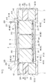
- FIG. 2 is a cross-sectional view schematically showing the reactor cut along a cutting line (II)-(II) in FIG.
- FIG. 3 is a partially exploded perspective view showing a part of a combination provided in the reactor according to the first embodiment.
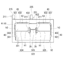
- FIG. 4 is a front view schematically showing a combined body provided in the reactor according to the first embodiment as viewed from the outside of the outer core portion.
- FIG. 5 is a front view schematically showing a combined body provided in the reactor according to the second embodiment as viewed from the outside of the outer core portion.
- FIG. 6 is a front view schematically showing a combined body provided in the reactor according to the third embodiment as viewed from the outside of the outer core portion.
- FIG. 7 is a front view schematically showing a combined body provided in the reactor according to the fourth embodiment as viewed from the outside of the outer core portion.
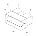
- FIG. 8 is a perspective view schematically illustrating a divided form of an outer core portion provided in a reactor according to the fifth embodiment.
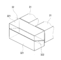
- FIG. 9 is a perspective view schematically showing a division form of an outer core portion provided in a reactor according to the sixth embodiment.
- the gap is reduced, it is difficult to fill the constituent resin of the inner resin portion between the winding portion and the inner core portion from the outer side of the outer core portion with respect to the combination of the coil and the magnetic core. Become.
- the outer core portion is arranged in the middle of the filling path of the constituent resin. Therefore, if the filling pressure or the holding pressure of the constituent resin is increased, the load on the outer core portion due to contact with the constituent resin increases. When a large load acts on the outer core, the outer core may be broken or damaged.
- an object of the present disclosure is to provide a reactor in which the gap is sufficiently filled with the resin without damaging the outer core even if the gap between the coil and the inner core is small. I do.
- the inventor of the present invention has proposed a method of filling a combination of a coil and a magnetic core with a component resin of an inner resin portion between a winding portion and an inner core portion from the outer side of an outer core portion. Increased pressure and holding pressure. As a result, it was found that the outer core portion may be split so as to be divided in the vertical direction (hereinafter, sometimes simply referred to as a crack of the outer core portion).
- the vertical direction refers to the side facing the inner core portion of the outer core portion as the inner side, the opposite side to the inner side as the outer side, and the inner and outer directions and the direction of the magnetic flux excited in the outer core portion. It refers to the direction orthogonal to both directions.
- the outer core portion is easily broken.
- the outer core portion is made of a green compact or a composite material. These materials are vulnerable to bending stress and tensile stress. A large bending stress acts on the outer core part due to contact with the constituent resin of the inner resin part at the time of filling, or the resin filled in the through hole pushes the inner surface of the through hole to the outside, so that the outer core part has a large bending stress. This is probably because tensile stress acts.
- the inventor of the present invention has studied diligently to prevent the outer core portion from cracking even when the filling pressure or the holding pressure is increased. As a result, the present inventor has proposed that the outer core portion be divided vertically by dividing the outer core portion in the vertical direction, so that the outer core portion is increased even when the filling pressure or the holding pressure is increased. It has been found that cracks can be suppressed.
- the reactor according to one embodiment of the present disclosure is: A coil having a winding portion formed by winding a winding, An inner core portion disposed inside the winding portion, and a magnetic core having an outer core portion disposed outside the winding portion, An inner resin portion filled between the inner peripheral surface of the winding portion and the outer peripheral surface of the inner core portion, a reactor comprising: The side of the outer core portion facing the inner core portion is defined as an inner side, and the side opposite to the inner side is defined as an outer side, and both directions of the inner and outer directions and the direction of magnetic flux excited in the outer core portion are provided.
- the outer core portion has a plurality of core pieces that are connected in the up-down direction through divided surfaces that intersect in the up-down direction,
- the inner core portion does not have a dividing surface that extends from one end side to the other end side in the inside and outside directions.
- the gap can be sufficiently filled with the constituent resin of the inner resin portion.
- the inner resin part is formed by filling the constituent resin of the inner resin part between the winding part and the inner core part from the outer side of the outer core part for the combined body that combines the coil and the magnetic core. it can.
- the reason that the gap can be sufficiently filled with the constituent resin is that the filling pressure and the holding pressure of the constituent resin can be increased. Even when the filling pressure and the holding pressure are increased, each core piece can behave individually with the divided surface interposed therebetween since the outer core portion has the divided surface that intersects in the vertical direction. Therefore, the load acting on the outer core portion due to contact with the constituent resin of the inner resin portion at the time of filling can be reduced. Therefore, it is possible to prevent the outer core portion from breaking so as to be divided in the vertical direction.
- the inner core portion does not have a split surface extending from one end in the inward / outward direction to the other end, a decrease in magnetic characteristics can be suppressed. If the inner core portion has the split surface, the inner core portion may be displaced inward and outward with the contact of the inner resin portion with the constituent resin when the inner resin portion is formed. However, the inner core portion does not have the above dividing surface. That is, the inner core portion is not divided in any of the vertical direction and the horizontal direction.
- the left-right direction refers to a direction orthogonal to both the vertical direction of the inner core portion and the direction of magnetic flux in the inner core portion (inward and outward directions). This is because there is no risk of the inner core portion shifting in the inward and outward directions when the inner resin portion is formed.
- the gap between the coil and the inner core can be reduced.
- the gap can be sufficiently filled with the constituent resin of the inner resin portion. Therefore, if the size of the inner core portion is fixed, the size of the coil can be reduced, so that the size of the reactor can be reduced. Alternatively, if the size of the coil is fixed, the magnetic path area of the inner core portion can be increased, so that the magnetic characteristics can be improved.
- the division surface of the outer core portion may include a surface parallel to the inward and outward directions.
- the coil and the inner core portion are compared with a case where the split surface has a surface (non-parallel surface) intersecting the outer core portion in the vertical direction and intersecting the inner and outer directions of the outer core portion. Is small, it is easy to sufficiently fill the gap with the constituent resin of the inner resin portion.
- the division surface is parallel to the filling direction of the resin, the core pieces are more likely to behave in a direction in which the core pieces are separated from each other than in a case where they are not parallel. For this reason, even if the filling pressure or the holding pressure is increased, the load acting on the outer core portion due to contact with the constituent resin of the inner resin portion at the time of filling is easily reduced. That is, cracks in the outer core portion are easily suppressed.
- the division surface of the outer core portion may include a surface orthogonal to the vertical direction.
- the gap between the coil and the inner core portion is smaller than that in a case where the divided surfaces intersect non-perpendicularly in the vertical direction of the outer core portion and have surfaces parallel to the inner and outer directions.
- the division planes are perpendicular to the vertical direction, it is easier to cause the core pieces to behave in a direction in which the core pieces are separated from each other as compared with a case where they intersect non-orthogonally. For this reason, even if the filling pressure or the holding pressure is increased, the load acting on the outer core portion due to contact with the constituent resin of the inner resin portion at the time of filling is easily reduced. That is, cracks in the outer core portion are easily suppressed.
- the outer core portion has a hole penetrating in the inward and outward directions,
- the division surface of the outer core portion may divide the hole portion in the vertical direction.
- the filling pressure and the holding pressure can be increased even with the hole.
- the constituent resin of the inner resin portion filled in the hole causes the inner surface of the hole to face outward. It is easy to ease the tensile stress acting on the outer core portion by expanding. That is, even if it has a hole, it is easy to suppress cracking of the outer core.
- the provision of the intermediate resin portion enables the hole portion to be sealed. Therefore, it is easy to prevent water droplets or the like from entering between the coil and the inner core portion through the hole. Further, by providing the outer resin portion, the outer core portion is easily protected from the external environment. Furthermore, the mechanical strength of the reactor (magnetic core) can be increased by connecting the inner resin portion and the outer resin portion via the intermediate resin portion in the hole.
- the inner resin portion and the outer resin portion are connected via an intermediate resin portion in the hole.
- the inner resin portion, the intermediate resin portion, and the outer resin portion can be formed by one molding. That is, it can be obtained by one resin molding despite having an intermediate resin portion and an outer resin portion in addition to the inner resin portion.
- Each of the core pieces may be formed of either a green compact containing soft magnetic powder or a composite material in which soft magnetic powder is dispersed in a resin.
- the outer core portion is provided with the divided surface, It is easy to suppress cracking.
- the green compact can increase the ratio of the soft magnetic powder in the core piece as compared with the composite material. For this reason, the green compact easily increases the magnetic properties (relative magnetic permeability and saturation magnetic flux density).
- the content of the soft magnetic powder in the resin can be easily adjusted. Therefore, the composite material can easily adjust the magnetic properties (the relative magnetic permeability and the saturation magnetic flux density). In addition, the composite material can be easily formed even in a complicated shape as compared with a green compact.
- Reactor 1 includes combination 10 and inner resin portion 5.
- the combination 10 is formed by combining the coil 2 and the magnetic core 3.
- the coil 2 has winding portions 21 and 22 formed by winding the windings 211 and 221.
- the magnetic core 3 has an inner core part 31 and an outer core part 32.
- the inner core part 31 is arranged inside the winding parts 21 and 22.
- the outer core part 32 is arranged outside the winding parts 21 and 22.
- the inner resin portion 5 is filled between the inner peripheral surfaces of the winding portions 21 and 22 and the outer peripheral surface of the inner core portion 31.
- the inner core portion 31 does not have a specific division surface, and a plurality of core pieces 321 in which the outer core portion 32 is connected in a specific direction via a specific division surface 322. And the point.
- a main characteristic portion of the reactor 1 a configuration of a portion related to the characteristic portion, and a main effect will be sequentially described. Thereafter, each configuration will be described in detail. Finally, a method for manufacturing the reactor 1 will be described.
- FIG. 3 omits a part of the configuration of the combination 10 (the winding portion 22 in FIG. 1 and the like) for convenience of explanation.
- the coil 2 includes a pair of winding portions 21 and 22 (FIG. 1).
- Each of the winding portions 21 and 22 is formed by spirally winding separate windings 211 and 221. Adjacent turns in each of the winding portions 21 and 22 in this example are in contact with each other. Adjacent turns in the winding portions 21 and 22 are not in contact with each other if the space between adjacent turns is so small that the inner resin portion 5 described below does not leak out from between adjacent turns. Is also good.
- the pair of winding portions 21 and 22 are electrically connected to each other. The details of the windings 211 and 221 and the manner of electrical connection will be described later.
- Each of the winding portions 21 and 22 is a hollow cylindrical body.
- each of the winding portions 21 and 22 in the present example is a rectangular tube shape.
- the square tubular shape refers to a shape in which the end surfaces of the winding portions 21 and 22 are rectangular (including a square shape) with rounded corners.
- the sizes of the winding portions 21 and 22 are the same as each other.
- the number of turns of each winding part 21 and 22 is the same as each other.
- the winding directions of the winding portions 21 and 22 are the same.
- the cross-sectional areas and the number of windings of the windings 211 and 221 of the winding portions 21 and 22 may be different from each other.
- the winding portions 21 and 22 are arranged side by side (parallel) such that the axial directions are parallel to each other.
- the magnetic core 3 includes a pair of inner core portions 31 and a pair of outer core portions 32. Each inner core portion 31 is disposed inside each of the winding portions 21 and 22.
- the inner core portion 31 means a portion of the magnetic core 3 along the axial direction of the winding portions 21 and 22. In this example, both ends of the portion of the magnetic core 3 along the axial direction of the winding portions 21 and 22 protrude outside the winding portions 21 and 22.
- the protruding part is also a part of the inner core part 31.
- the outer core part 32 is arranged outside each of the winding parts 21 and 22. That is, the coil 2 is not disposed on the outer core portion 32, and is projected (exposed) from the coil 2.
- the magnetic core 3 has an outer core portion 32 disposed so as to sandwich the inner core portion 31 that is spaced apart, and is formed in an annular shape by contacting an end surface of the inner core portion 31 and an inner end surface of the outer core portion 32. You. When the coil 2 is excited by the inner core portion 31 and the outer core portion 32, a closed magnetic path is formed.
- the shape of the outer core portion 32 is a columnar body having a substantially dome-shaped upper surface and a lower surface in this example (FIGS. 1 and 3).
- the shape of the outer core portion 32 may be a rectangular parallelepiped or the like.
- the side of the outer core portion 32 facing the inner core portion 31 is defined as an inner side, and the side opposite to the inner side is defined as an outer side.
- a direction perpendicular to both the inside and outside directions of the outer core portion 32 and the direction of the magnetic flux in the outer core portion 32 is defined as a vertical direction (height direction).
- the direction of the magnetic flux in the outer core portion 32 is a direction along the parallel direction of the pair of winding portions 21 and 22 (the left-right direction in FIG. 4).
- the height of the outer core part 32 is larger than the inner core part 31 (FIG. 2).
- the upper surface of the outer core portion 32 is substantially flush with the upper surface of the inner core portion 31.
- the lower surface of the outer core portion 32 is substantially flush with the lower surface of the coil 2.
- the outer core 32 may have the same height as the inner core 31.
- Each outer core part 32 has a plurality of columnar core pieces 321 (Figs. 3 and 4).
- the plurality of core pieces 321 are connected via divided surfaces 322 that intersect in the vertical direction. That is, the division surface 322 divides the outer core portion 32 in the up-down direction.
- the connection between the plurality of core pieces 321 is performed by an outer resin portion 7 described later in this example (FIGS. 1 and 2).
- the split surface 322 is a surface that passes through the outer core portion 32 from the outer side toward the inner side (FIG. 2). 1 to 4 exaggerate the division surface 322 for convenience of explanation.
- the core pieces 321 are preferably in direct contact with substantially no gap.
- the core piece 321 is formed of a green compact or a composite material. The material of the core piece 321 will be described later.
- the inner resin portion 5 is formed by filling the resin of the inner resin portion 5 between the winding portions 21 and 22 and the inner core portion 31 from the outer side of the outer core portion 32 in the combined body 10. It can.
- the reason for sufficiently filling the gap with the constituent resin is that the filling pressure and holding pressure of the constituent resin in the inner resin portion 5 can be increased.
- the number of divided surfaces of each outer core portion 32 and the number of core pieces 321 can be appropriately selected.
- the number of the division planes 322 in this example is one. That is, the number of the core pieces 321 in this example is two. Note that the number of the divided surfaces 322 may be two or more. That is, the number of core pieces 321 may be three or more.
- Examples of the division surface 322 that intersects the outer core portion 32 in the vertical direction and divides the plurality of core pieces 321 in the vertical direction include the following (1) or (2).
- the division surface 322 has a surface (non-parallel surface) that intersects the inner and outer directions of the outer core portion 32. That is, the division surface 322 has a surface (non-parallel surface) that intersects in the vertical direction of the outer core portion 32 and intersects inward and outward of the outer core portion 32.
- the dividing surface 322 has a surface parallel to the inside and outside directions of the outer core portion 32. That is, the split surface 322 has a surface that intersects the upper and lower directions of the outer core portion 32 and is parallel to the inner and outer directions of the outer core portion 32.
- the cross-sectional shape of the dividing surface 322 may be a polygonal line shape, a curved shape, an inclined shape, or the like.
- the polygonal line shape include a V shape, an N shape, and a W shape.
- the curved shape include an arc shape, an S shape, and a sine wave shape.
- the cross-sectional shape of the division surface 322 refers to the shape of a line represented by the edge of the division surface 322 on the first cut surface of the outer core portion 32.
- the first cut surface of the outer core portion 32 refers to a surface orthogonal to the direction of magnetic flux in the outer core portion 32 (the parallel direction of the pair of winding portions 21 and 22).
- each end of the division surface 322 intersects each of the left and right sides of the outer core portion 32.
- the division surface 322 satisfies the above-described mode (2). Even if the gap between the winding portions 21 and 22 and the inner core portion 31 is smaller than that in the case where the division surface 322 satisfies the above-described mode (1), the constituent resin of the inner resin portion 5 is filled in the gap. This is because it is easy to sufficiently fill. Even when the filling pressure and the holding pressure at the time of forming the inner resin portion 5 are increased, compared with the case where the division surface 322 satisfies the above-described mode (1), the difference between the divided surface 322 and the constituent resin of the inner resin portion 5 at the time of filling is increased. It is easy to reduce the load acting on the outer core portion 32 due to contact or the like.
- Examples of the above-mentioned form (2) include any of the following forms (2-1) to (2-3).
- the split surface 322 has a surface that intersects the outer core portion 32 in a non-perpendicular direction in the vertical direction.
- the division surface 322 has a surface that intersects non-perpendicularly in the vertical direction of the outer core portion 32 and is parallel to the inner and outer directions of the outer core portion 32.
- This division surface 322 is a surface that intersects the magnetic flux in the outer core portion 32.
- the dividing surface 322 has a surface perpendicular to the vertical direction of the outer core portion 32. This orthogonal surface is a surface parallel to the inward and outward directions of the outer core portion 32.
- the division surface 322 is a surface parallel to the magnetic flux in the outer core portion 32.
- the division surface 322 has a surface that intersects the outer core 32 non-perpendicularly in the vertical direction and a surface that intersects the outer core 32 vertically. That is, the division surface 322 has a surface that intersects non-perpendicularly in the vertical direction of the outer core portion 32 and is parallel to the inside and outside directions of the outer core portion 32 and a surface that is perpendicular to the vertical direction of the outer core portion 32.
- the division surface 322 satisfies the above-mentioned form (2-2). Even if the gap between the winding portions 21 and 22 and the inner core portion 31 is smaller than the case where the division surface 322 satisfies the above (2-1) and (2-3), This is because it is easy to sufficiently fill the constituent resin of the inner resin portion 5. Even when the filling pressure and the holding pressure at the time of forming the inner resin portion 5 are increased, the inner surface at the time of filling is smaller than the case where the division surface 322 satisfies the above (2-1) and (2-3). The load acting on the outer core portion 32 due to contact with the constituent resin of the resin portion 5 or the like is easily reduced. That is, cracking of the outer core portion 32 is easily suppressed.
- the vertical sectional shape of the division surface 322 may be a polygonal line shape, a curved shape, an inclined shape, or the like.
- the polygonal line shape include a V shape, an N shape, and a W shape.
- the curved shape include an arc shape, an S shape, and a sine wave shape.
- the vertical cross-sectional shape of the division surface 322 refers to the shape of a line represented by the edge of the division surface 322 on the second cut surface of the outer core portion 32.
- the second cut surface of the outer core portion 32 is a surface parallel to both the vertical direction of the outer core portion 32 and the direction of the magnetic flux in the outer core portion 32 (the parallel direction of the pair of winding portions 21 and 22).
- each end of the divided surface 322 may intersect with each of the left and right sides of the outer core portion 32, or the upper side, the lower side, and the upper corner of the outer core portion 32. Part or the lower corner may be crossed.
- the vertical cross-sectional shape of the division surface 322 may be a flat shape. In this case, since the division surface 322 is parallel without crossing the magnetic path, the magnetic characteristics are excellent.
- the outer core portion 32 is divided into three in the direction of the magnetic path, and the division surface 322 is divided into a central division surface 323, a left division surface 324, and a right division surface 325.
- the central split surface 323 is formed of a surface that intersects the outer core portion 32 in a non-perpendicular direction in the vertical direction and that is parallel to the inner and outer directions of the outer core portion 32, for example, a V-shaped surface.
- the left divided surface 324 and the right divided surface 325 are formed by surfaces perpendicular to the vertical direction of the outer core portion 32.
- left divided surface 324 and the right divided surface 325 intersect non-perpendicularly in the vertical direction of the outer core portion 32 and are parallel to the inner and outer directions of the outer core portion 32, for example, inclined surfaces. I do.
- the central divided surface 323 is configured by a surface orthogonal to the vertical direction of the outer core portion 32.
- the dividing surface 322 of this example has the form of the above (2-2). That is, the division surface 322 is configured by a surface orthogonal to the vertical direction of the outer core portion 32.
- the vertical cross-sectional shape of the division surface 322 is a plane shape.
- the position where the division surface 322 is formed in the vertical direction is preferably a position at which the hole 35 is divided.
- the resin filled in the hole 35 pushes the inner peripheral surface of the hole 35 outward, so that a large tensile stress acts on the outer core 32.
- each of the core pieces 321 can behave individually by dividing the hole 35 by the division surface 322, the force for pushing and expanding the inner peripheral surface of the hole 35 can be reduced. That is, the tensile stress acting on the outer core portion 32 can be reduced. Therefore, it is easy to suppress the damage of the outer core portion 32 due to the filling of the constituent resin when the inner resin portion 5 is formed.
- the vertical formation position of the division surface 322 is a position that divides the center of the hole 35 in the vertical direction.
- the divided surface 322 has a central divided surface 323 provided between the holes 35, a left divided surface 324 and a right divided surface 325 provided outside the holes 35.
- the center division surface 323, the left division surface 324, and the right division surface 325 are located on the same plane.
- at least one of the center division surface 323, the left division surface 324, and the right division surface 325 may be located on a plane different from other division surfaces. .
- the outer core 32 has a hole 35 penetrating in and out of the outer core 32. That is, the opening of the hole 35 is formed on the outer surface and the inner surface of the outer core portion 32.
- the hole 35 serves as a filling path for filling the constituent resin of the inner resin portion 5 into the winding portions 21 and 22 when the inner resin portion 5 is formed.
- the number of the holes 35 can be appropriately selected, and may be a single number or a plurality. The number of the holes 35 in this example is two.
- each hole 35 The opening on the inner side of each hole 35 is open at a position facing the gap h1 (FIG. 4) between the inner peripheral surfaces of the winding portions 21 and 22 and the outer peripheral surface of the inner core portion 31.
- the gap h1 is formed in the cylindrical space between the inner peripheral surface of each of the winding portions 21 and 22 and the outer peripheral surface of each of the inner core portions 31 near the center in the parallel direction of each of the winding portions 21 and 22. This is a gap between the peripheral surface and the inner core portion 31 disposed inside each of the winding portions 21 and 22.
- each hole 35 can be appropriately selected so that the magnetic path of the outer core 32 is not excessively narrowed.
- the length of each hole 35 along the vertical direction of the outer core portion 32 is preferably 10% or more and 50% or less of the length (height) of the outer core portion 32 in the vertical direction. If the length of each hole 35 is 10% or more of the height of the outer core 32, it is easy to provide a path for filling the constituent resin of the inner resin 5. If the length of each hole 35 is 50% or less of the height of the outer core 32, the magnetic path of the outer core 32 will not be too narrow.
- the lower limit of the length of each hole 35 can be 20% or more of the height of the outer core 32, and can be 25% or more.
- the upper limit of the length of each hole 35 can be 40% or less of the height of the outer core portion 32, and can be 30% or less.
- the length (width) of each hole 35 along the magnetic path direction affects the magnetic characteristics and strength of the outer core 32. Therefore, the length (width) of each hole 35 can be appropriately selected so that the magnetic characteristics and strength of the outer core 32 do not decrease.
- the edge of the opening on the outer side of each hole 35 is chamfered.
- the edge of the opening on the outer side of each hole 35 is chamfered.
- each inner core portion 31 be a shape that matches the inner peripheral shape of the winding portions 21 and 22.
- the shape of the inner core portion 31 of the present example is a rectangular parallelepiped. The corners of the inner core portion 31 are rounded along the inner peripheral surfaces of the winding portions 21 and 22.
- Each inner core portion 31 has a plurality of columnar core pieces 311 (FIG. 2).
- the direction along the up-down direction of the outer core part 32 in the inner core part 31 is called the up-down direction.
- a direction orthogonal to both the vertical direction of the inner core portion 31 and the direction of the magnetic flux in the inner core portion 31 is defined as a left-right direction.
- the direction of the magnetic flux in the inner core portion 31 is a direction along the axial direction of the winding portions 21 and 22.
- the plurality of core pieces 311 are divided surfaces that intersect the direction of the magnetic flux in the inner core portion 31 and are connected via a divided surface that passes from the upper surface of the inner core portion 31 to the lower surface (from the left side to the right side). . That is, the division surface divides the inner core portion 31 in the direction of the magnetic flux.
- the number of core pieces 311 in each inner core portion 31 can be appropriately selected.
- the number of core pieces 311 in this example is three.
- the number of the division planes is two.
- Each division surface in this example is orthogonal to the magnetic flux in the inner core portion 31. That is, the shape of each core piece 311 is the same prismatic shape.
- each of the inner core portions 31 is configured by a laminated body in which the core pieces 311 and the gaps 312 and 313 are laminated and arranged along the axial direction of the coil 2 (the magnetic flux direction in the inner core portion 31).
- the core piece 311 is made of a green compact or a composite material. The materials of the core piece 311 and the gaps 312 and 313 will be described later.
- Each inner core portion 31 does not have a split surface extending from one end surface to the other end surface in the direction along the magnetic flux in the inner core portion 31.
- the one end surface and the other end surface in the direction along the magnetic flux in the inner core portion 31 are surfaces orthogonal to the magnetic flux in this example. That is, this division surface is a surface that divides the inner core portion 31 in the up-down direction or the left-right direction. Having no division surface, the inner core portion 31 is not divided in any of the vertical direction and the horizontal direction. That is, the inner core portion 31 does not have a plurality of core pieces divided in the vertical direction and the horizontal direction. Since the inner core portion 31 does not have the division surface, a decrease in magnetic characteristics can be suppressed. This is because, when the inner resin portion 5 is formed, the inner core portion 31 does not shift in the above-described inner and outer directions due to contact with the constituent resin of the inner resin portion 5.
- each inner core portion 31 may be formed of a single columnar core piece having no division surface.
- the core piece has substantially the entire axial length of the winding portions 21 and 22 without a gap.
- the inner resin portion 5 joins the inner peripheral surface of the winding portion 22 and the outer peripheral surface of the inner core portion 31 (core piece 311). Although not shown, the same applies to the winding part 21 (FIG. 1).
- the inner resin portion 5 is interposed in a cylindrical space between the inner peripheral surface of each of the winding portions 21 and 22 and the outer peripheral surface of each of the inner core portions 31.
- the inner resin portion 5 is formed over substantially the entire area of the cylindrical space.
- the inner resin portion 5 of this example remains inside each of the winding portions 21 and 22 and does not overflow into the outer periphery of each of the winding portions 21 and 22 from between the turns.
- a part of the inner resin portion 5 can be less likely to overflow from between the turns to the outer periphery of the winding portions 21 and 22.
- a part of the inner resin portion 5 of the present example enters between the core pieces 311 in the inner core portion 31 and between the core piece 311 and the outer core portion 32 to form gaps 312 and 313.
- thermosetting resin examples include an epoxy resin, a phenol resin, a silicone resin, and a urethane resin.
- examples of the thermoplastic resin include polyphenylene sulfide (PPS) resin, polyamide (PA) resin (for example, nylon 6, nylon 66, nylon 9T, etc.), liquid crystal polymer (LCP), polyimide resin, and fluororesin.
- PPS polyphenylene sulfide
- PA polyamide
- LCP liquid crystal polymer
- polyimide resin polyimide resin
- fluororesin examples include fluororesin.
- these resins may contain a ceramic filler. Examples of the ceramic filler include alumina and silica. The inner resin portion 5 containing the ceramic filler can improve the heat dissipation of the inner resin portion 5.
- the reactor 1 according to the first embodiment has the following effects.
- the gap can be sufficiently filled with the constituent resin of the inner resin portion 5. This is because the filling pressure and the holding pressure at the time of forming the inner resin portion 5 can be increased. Even if the filling pressure and the holding pressure are increased, the outer core portion 32 has the dividing surface 322 perpendicular to the vertical direction, so that the outer core portion 32 contacts the constituent resin of the inner resin portion 5 at the time of filling, and so on. The acting load can be reduced. In particular, the dividing surface 322 vertically divides the hole 35 so that the constituent resin of the inner resin portion 5 filled in the hole 35 pushes the inner surface of the hole 35 outward to spread the outer core portion 32. It is easy to reduce the tensile stress acting on the surface. For this reason, it is possible to suppress the outer core portion 32 from splitting vertically.
- the gap between the winding portions 21 and 22 and the inner core portion 31 can be reduced. This is because, as in the above (1), even if the gap between the winding portions 21 and 22 and the inner core portion 31 is small, the gap can be sufficiently filled with the constituent resin of the inner resin portion 5. Therefore, if the size of the inner core portion 31 is fixed, the size of the coil 2 can be reduced, so that the size of the reactor 1 can be reduced. Alternatively, if the size of the coil 2 is fixed, the magnetic path area of the inner core portion 31 can be increased, so that the magnetic characteristics can be improved.
- a covered wire having an insulating coating on the outer periphery of the conductor wire can be used.
- the material of the conductor wire include copper, aluminum, magnesium, and alloys thereof.
- Examples of the type of the conductor wire include a flat wire and a round wire.
- Examples of the insulating coating include enamel (typically, polyamideimide).
- a conductor wire is a rectangular wire made of copper, and an insulating coating is a rectangular wire coated with enamel (typically, polyamideimide).
- Each of the winding portions 21 and 22 is constituted by an edgewise coil formed by edgewise winding the covered rectangular wire.
- Both ends 215 and 225 of each of the windings 211 and 221 are extended upward at both axial ends of the coil 2. Both ends 215 and 225 of each of the windings 211 and 221 have their conductors exposed by removing the insulation coating.
- the conductors at the ends 215 and 225 at one end in the axial direction of the coil 2 (the right side in FIG. 1) are directly connected to each other. More specifically, the winding portion 22 is bent at the end 225 side of the winding 221 and stretched and connected to the end 215 side of the winding 211 of the winding portion 21.
- the connection between the conductors may be performed via a connection member independent of the pair of winding portions 21 and 22.
- the connecting member is made of, for example, the same member as the windings 211 and 221. This connection can be made by welding or pressure welding.
- a terminal member (not shown) is connected to the conductors at the ends 215 and 225 on the other end side (left side in FIG. 1) of the coil 2 in the axial direction.
- the coil 2 is connected to an external device (not shown) such as a power supply for supplying power to the coil 2 via the terminal member.
- the winding portions 21 and 22 may be individually integrated by an integrated resin (not shown).
- the integrated resin covers the outer peripheral surface, the inner peripheral surface, and the end surface of each of the winding portions 21 and 22, and joins adjacent turns.
- As the integrated resin one having a coating layer of a heat-sealing resin formed on the outer periphery of the windings 211 and 221 (further outer periphery of the insulating coating) is used, and after winding the windings 211 and 221, heating is performed. And melting the coating layer.
- the type of the heat sealing resin include a thermosetting resin such as an epoxy resin, a silicone resin, and an unsaturated polyester.
- the pair of winding portions 21 and 22 provided in the coil 2 may be formed by a single winding.
- the shape of the winding portions 21 and 22 may be cylindrical.
- the term “cylindrical” means that the end faces of the winding portions 21 and 22 have an elliptical shape, a perfect circle shape, a race track shape, or the like.
- the core piece 311 of the inner core part 31 and the core piece 321 of the outer core part 32 are formed of a green compact or a composite material.
- the green compact is formed by compression molding a soft magnetic powder.
- the green compact can increase the ratio of the soft magnetic powder in the core piece as compared with the composite material. For this reason, the green compact easily increases the magnetic properties (relative magnetic permeability and saturation magnetic flux density).
- the composite material has a soft magnetic powder dispersed in a resin.
- the composite material is obtained by filling a mold with a fluid material in which soft magnetic powder is dispersed in an unsolidified resin, and curing the resin. The composite material can easily adjust the content of the soft magnetic powder in the resin.
- the composite material can easily adjust the magnetic properties (the relative magnetic permeability and the saturation magnetic flux density).
- the composite material can be easily formed even in a complicated shape as compared with a green compact.
- the core pieces 311 and 321 may be hybrid cores in which the outer periphery of the green compact is covered with a composite material.
- the particles constituting the soft magnetic powder include soft magnetic metal particles, coated particles having an insulating coating on the outer periphery of the soft magnetic metal particles, and soft magnetic non-metal particles.
- the soft magnetic metal include pure iron and iron-based alloys (Fe—Si alloy, Fe—Ni alloy, etc.).
- the insulating coating include phosphate.
- Soft magnetic non-metals include ferrite and the like.
- the resin of the composite material for example, the same resin as the above-described inner resin portion 5 can be used.
- the gaps 312 and 313 are made of a material having a lower relative magnetic permeability than the core piece 311.
- the gaps 312 and 313 in the present example are formed by the inner resin portion 5.
- (Intermediate resin part) Reactor 1 may have intermediate resin portion 6 (FIG. 2).
- the intermediate resin portion 6 is filled in the hole 35 of the outer core portion 32.
- the intermediate resin portion 6 can seal the inside of the hole 35. For this reason, the intermediate resin portion 6 easily prevents intrusion of water droplets and the like between the coil 2 and the inner core portion 31 through the hole 35.
- the intermediate resin part 6 is connected to the inner resin part 5.
- the intermediate resin portion 6 is formed by filling a part of the inner resin portion 5 into the hole portion 35 when the hole portion 35 is used as a filling path of the inner resin portion 5 when the inner resin portion 5 is formed. You. That is, the intermediate resin part 6 and the inner resin part 5 are formed of the same resin at one time.
- (Outer resin part) Reactor 1 may have outer resin portion 7.
- the outer resin portion 7 protects the outer core portion 32 from the external environment (FIGS. 1 and 2).
- the outer resin portion 7 covers a region of the outer peripheral surface of each outer core portion 32 except for a connection surface with the inner core portion 31.
- the lower surface of the outer core portion 32 may be exposed from the outer resin portion 7.
- the lower surface of the outer core portion 32 is made to protrude below the lower surface of the coil 2, or when the reactor 1 includes an end member 41 described below, the lower surface of the outer member 32 is substantially flush with the lower surface of the end member 41. It is preferable to make them protrude.
- the heat radiation of the magnetic core 3 including the outer core portion 32 can be enhanced.
- the heat radiation of the magnetic core 3 including the outer core portion 32 can be enhanced by interposing an adhesive or a heat radiation sheet between the lower surface of the outer core portion 32 and the installation target surface of the reactor 1.
- the outer resin portion 7 can fix each outer core portion 32 to the end face member 41.
- the outer resin portion 7 is connected to the inner resin portion 5 via the intermediate resin portion 6 in the hole 35 of the outer core portion 32.
- the outer resin portion 7 can be formed by covering the outer periphery of the outer core portion 32 with the constituent resin of the inner resin portion 5 when the inner resin portion 5 is formed.
- the outer resin portion 7, the intermediate resin portion 6, and the inner resin portion 5 are formed of the same resin at one time. Note that the outer resin portion 7 can be formed separately from the inner resin portion 5.
- a fixing portion 71 may be formed on the outer resin portion 7 (FIG. 1).
- the fixing unit 71 fixes the reactor 1 to a surface to be installed (for example, a bottom surface of a case).
- the fixing portion 71 is formed integrally with the outer resin portion 7 using the constituent material of the outer resin portion 7.
- the formation part of the fixing part 71 can be appropriately selected according to the position of the attachment part in the installation target of the reactor 1.
- the fixing portion 71 of this example is provided in a flange shape so as to protrude from the outer end surface of the outer resin portion 7 in the parallel direction of the coil 2.
- a collar made of a highly rigid metal or resin is embedded. With this collar, it is easy to suppress creep deformation due to a fastening member (for example, a bolt) that fixes the reactor 1 to the installation target surface.
- the collar has an insertion hole for the fastening member.
- the union 10 may include the intervening member 4 (FIGS. 1 to 4).
- the interposition member 4 secures insulation between the coil 2 and the magnetic core 3.
- the intervening member 4 of this example has a pair of end surface members 41 and a number of inner members 42 corresponding to the number of the inner core portions 31.
- Each end face member 41 secures insulation between each end surface of the coil 2 and each outer core portion 32.
- the shape of each end face member 41 is the same.
- Each end face member 41 is a frame-shaped plate member in which two through holes 410 are provided along the direction in which the winding portions 21 and 22 are arranged in parallel. In each through hole 410, a combination of the inner core portion 31 (core piece 311) and the inner member 42 is fitted.
- a braid in which the outer core portion 32 is fitted into a concave portion 412 (described later) of the end face member 41 is viewed from the outside of the outer core portion 32 (FIG. 4).
- a gap h3 exposed from the outer core portion 32 is formed on the upper side and the outer side of each through hole 410 (see also FIG. 2).
- the gap h3 communicates with a gap h2 (FIG. 2) formed between the inner peripheral surface of the connecting portion 432 and the outer peripheral surface of the inner core portion 31 (core piece 311) in the end piece 43 described later. . That is, the gap h3 communicates with the space between the inner peripheral surfaces of the winding portions 21 and 22 and the outer peripheral surface of the inner core portion 31 (core piece 311).
- This gap h3 can be used for the filling path of the inner resin portion 5.
- Each concave portion 411 for accommodating the end surfaces of the winding portions 21 and 22 are formed in the surface of each end surface member 41 on the coil 2 side (see the right side of FIG. 3).
- Each concave portion 411 on the coil 2 side brings the entire end surface of the winding portion 21 or 22 into surface contact with the end member 41.
- Each recess 411 is formed in a rectangular ring shape so as to surround the periphery of the through hole 410.
- the right side portion of each recess 411 reaches the upper end of the end face member 41 so that the ends 215 and 225 of the winding portions 21 and 22 can be pulled out upward.
- One concave portion 412 into which the outer core portion 32 is fitted is formed on the surface of each end surface member 41 on the side of the outer core portion 32 (see the left side of FIG. 3).
- the inner member 42 secures insulation between the outer peripheral surfaces of the inner core portions 31 and the inner peripheral surfaces of the winding portions 21 and 22 (FIG. 3).
- Each inner member 42 has the same configuration.
- Each of the inner members 42 of the present example includes a pair of end pieces 43 for each of the inner core portions 31 and a plurality (two in this example) of intermediate pieces 44 for each of the inner core portions 31.
- the end piece 43 is interposed between each outer core part 32 and each core piece 311.
- Each end piece 43 is a rectangular frame-shaped member.
- Each end piece 43 has an abutment portion 431 and a connecting portion 432.
- the abutment portion 431 abuts the core piece 311 and forms a predetermined length of a separation portion between the core piece 311 and the outer core portion 32.
- the contact stoppers 431 are provided at the four corners of the end piece 43.
- the width of the abutment portion 431 in the axial direction of the inner core portion 31 is wider than the width of the connecting portion 432.
- the connecting portion 432 connects the contact stoppers 431 to each other.
- the outer peripheral surface of the connecting portion 432 contacts the inner peripheral surfaces of the winding portions 21 and 22.
- the inner peripheral surface of the connecting portion 432 does not contact the outer peripheral surface of the core piece 311 and forms gaps h1 and h2 with the core piece 311 (FIGS. 2 and 4).
- the gaps h ⁇ b> 1 and h ⁇ b> 2 serve as a filling path for the inner resin portion 5.
- the intermediate piece 44 is interposed between the adjacent core pieces 311.
- Each intermediate piece 44 is a substantially U-shaped member.
- Each intermediate piece 44 is provided with an abutment portion 441 (see FIG. 2) for abutting the core piece 311.
- the abutment portion 441 forms a separation portion having a predetermined length between the adjacent core pieces 311.
- the inner resin portion 5 enters these separated portions.
- the inner resin portion 5 that has entered the separation portion forms gaps 312 and 313 (see FIG. 2).
- Examples of the material of the interposed member 4 include insulating materials such as various resins.
- the resin for example, the same resin as the above-described inner resin portion 5 can be used.
- Other thermoplastic resins include, for example, polytetrafluoroethylene (PTFE) resin, polybutylene terephthalate (PBT) resin, acrylonitrile butadiene styrene (ABS) resin, and the like.
- thermosetting resins include, for example, unsaturated polyester resins.
- the material of the interposition member 4 is preferably the same as the material of the inner resin portion 5. This is because the linear expansion coefficients of the interposed member 4 and the inner resin portion 5 can be made the same, and damage to each member due to thermal expansion and contraction can be suppressed.
- the reactor 1 can be used as a component of a power conversion device such as a bidirectional DC-DC converter mounted on an electric vehicle such as a hybrid vehicle, an electric vehicle, or a fuel cell vehicle.
- a power conversion device such as a bidirectional DC-DC converter mounted on an electric vehicle such as a hybrid vehicle, an electric vehicle, or a fuel cell vehicle.
- the reactor 1 of this example can be used in a state of being immersed in a liquid refrigerant.
- the type of the liquid refrigerant is not particularly limited, but when the reactor 1 is used in a hybrid vehicle, an ATF (Automatic Transmission Transmission) or the like may be used.
- a fluorine-based inert liquid a chlorofluorocarbon-based refrigerant, an alcohol-based refrigerant, a ketone-based refrigerant, or the like can be used.
- the fluorinated inert liquid include Fluorinert (registered trademark).
- Examples of the CFC-based refrigerant include HCFC-123 and HFC-134a.
- Examples of the alcohol-based refrigerant include methanol and alcohol.
- Examples of the ketone-based refrigerant include acetone.
- the winding portions 21 and 22 are exposed to the outside. Therefore, when cooling reactor 1 with a cooling medium such as a liquid refrigerant, winding portions 21 and 22 can be brought into direct contact with the cooling medium. Therefore, the reactor 1 of this example is excellent in heat dissipation.
- the reactor 1 is prepared by preparing a combined body 10 in which the coil 2, the core pieces 311, 321 and the interposition member 4 are combined, filling resin between the winding parts 21, 22 and the core piece 311 and curing the resin. Can be manufactured.
- the assembly is placed in a molding die (not shown), and injection molding is performed to inject resin into the molding die.
- the resin is injected from two injection holes of a molding die. Each injection hole is provided at a position corresponding to both holes 35 of each outer core portion 32. That is, the resin is injected by filling both sides of the outer core 32 from the outside (the side opposite to the coil 2).
- the resin filled in the molding die covers the outer periphery of the outer core portion 32 and flows into the winding portions 21 and 22 through the holes 35 of the outer core portion 32.
- the resin flows around the outer peripheral surface of the outer core portion 32 and flows into the winding portions 21 and 22 through the gap h3 (filling path) of the end face member 41.
- the resin filled in the winding portions 21 and 22 not only enters between the inner peripheral surfaces of the winding portions 21 and 22 and the outer peripheral surface of the core piece 311, but also between adjacent core pieces 311. And it enters also between the core piece 311 and the outer core part 32. Resin mixed between the adjacent core pieces 311 and between the core piece 311 and the outer core portion 32 forms gaps 312 and 313.
- the resin filled in the winding portions 21 and 22 by applying pressure by injection molding sufficiently spreads into a narrow gap between the winding portions 21 and 22 and the inner core portion 31. However, the resin hardly leaks outside the winding portions 21 and 22. This is because adjacent turns in the winding portions 21 and 22 are in contact with each other.
- the resin is filled in the winding portions 21 and 22, the resin is cured by heat treatment or the like.
- the resin inside the winding portions 21 and 22 becomes the inner resin portion 5 as shown in FIG.
- the resin in the hole 35 of the outer core portion 32 becomes the intermediate resin portion 6.
- the resin covering the outer core portion 32 becomes the outer resin portion 7.
- Embodiment 2 >> (Reactor)
- a reactor according to the second embodiment will be described with reference to FIG.
- the reactor according to the second embodiment among the division surfaces 322 of the outer core portion 32, at least one of the central division surface 323, the left division surface 324, and the right division surface 325 is different from the other division surfaces. The difference is that it is located above.
- the differences will be mainly described. The description of the same configuration is omitted.
- the center division surface 323, the left division surface 324, and the right division surface 325 are all formed of surfaces perpendicular to the outer core portion 32 in the up-down direction.
- the vertical division positions of the center division surface 323, the left division surface 324, and the right division surface 325 are positions that divide the hole 35 in the vertical direction of the outer core portion 32.
- the center division surface 323 is located on a plane different from the left division surface 324 and the right division surface 325.
- the left division surface 324 and the right division surface 325 are located on the same plane.
- the center division surface 323 is located above the left division surface 324 and the right division surface 325. Specifically, the central dividing surface 323 is formed above the center of the hole 35 in the vertical direction.
- the left divided surface 324 and the right divided surface 325 are formed below the center of the hole 35 in the vertical direction.
- the center division surface 323 may be located below the left division surface 324 and the right division surface 325. All of the center division surface 323, the left division surface 324, and the right division surface 325 may be located on different planes.
- the reactor of the present embodiment is excellent in manufacturability. Since the left dividing surface 324 and the right dividing surface 325 and the central dividing surface 323 are located on different planes, the upper and lower core pieces 321 can be easily fitted by the unevenness of the dividing surface 322. Therefore, the reactor of the present embodiment is easy to position the upper and lower core pieces 321 of the outer core portion 32.
- Embodiment 3 >> (Reactor)
- the reactor according to the third embodiment will be described with reference to FIG.
- the reactor according to the third embodiment differs from the first embodiment in that the outer core portion 32 has no hole 35 (FIGS. 1 to 4).
- the division surface 322 of the outer core portion 32 is constituted only by a surface orthogonal to the vertical direction.
- the vertical cross-sectional shape of the division surface 322 is a plane shape.
- the division surface 322 is located on the same plane.
- the vertical formation position of the division surface 322 is, for example, the vertical position of the outer core portion 32 below the vertical center of the outer core portion 32.
- Embodiment 4 (Reactor)
- the reactor according to the fourth embodiment will be described with reference to FIG.
- the reactor according to the fourth embodiment is different from the first embodiment in that the outer core portion 32 does not have the hole 35 (FIGS. 1 to 4) and the vertical cross-sectional shape of the dividing surface 322 of the outer core portion 32. I do. That is, the reactor according to the fourth embodiment is different from the reactor according to the third embodiment in the vertical cross-sectional shape of the divided surface 322 of the outer core portion 32.
- the division surface 322 of the outer core portion 32 is formed of only a surface that intersects the outer core portion 32 vertically and non-orthogonally and is parallel to the inner and outer directions of the outer core portion 32.
- the divided surface 322 has a V-shape.
- each end of the V-shaped divided surface 322 intersects each of the left and right sides of the outer core portion 32.
- the vertical formation position of the division surface 322 refers to a region from the vertical center of the outer core portion 32 to ⁇ 20% of the vertical length of the outer core portion 32 as in the third embodiment. In this example, this area includes all of the division planes 322.
- the reactor of the present embodiment is excellent in manufacturability. Since the vertical cross-sectional shape of the divided surface 322 is a V-shape, the core pieces 321 in the vertical direction can be fitted to each other by the unevenness of the divided surface 322. Therefore, the reactor of the present embodiment is easy to position the upper and lower core pieces 321 of the outer core portion 32.
- Embodiment 5 (Reactor)
- the reactor according to the fifth embodiment will be described with reference to FIG.
- the reactor according to the fifth embodiment differs from the first embodiment in that the outer core portion 32 does not have the hole 35 (FIGS. 1 to 4) and the form of the division surface 322 of the outer core portion 32.
- FIG. 8 shows the shapes of the inner core portion 31 and the outer core portion 32 in a simplified manner, unlike FIG. This is the same in FIG. 9 described later.
- the split surface 322 of the outer core portion 32 has a surface (a non-parallel surface) that intersects the outer core portion 32 in the vertical direction and intersects the inner and outer directions of the outer core portion 32.
- the cross-sectional shape of the divided surface 322 is V-shaped.
- each end of the V-shaped split surface 322 intersects each of the left and right (inward and outward) sides of the outer core portion 32.
- the vertical formation position of the division surface 322 is, as in the third and fourth embodiments described above, a region from the vertical center of the outer core portion 32 to ⁇ 20% of the vertical length of the outer core portion 32. To tell. In this example, this area includes all of the division planes 322. In this example, the V-shaped division surface 322 is formed so as to protrude upward in the outer core portion 32, but may be formed so as to protrude downward.
- Embodiment 6 (Reactor)
- a reactor according to the sixth embodiment will be described with reference to FIG.
- the reactor according to the sixth embodiment is different from the first embodiment in that the outer core portion 32 does not have the hole 35 (FIGS. 1 to 4) and the form of the dividing surface 322 of the outer core portion 32.
- the reactor according to the sixth embodiment is different from the reactor of the fifth embodiment in the cross-sectional shape of the divided surface 322 of the outer core portion 32.
- the cross-sectional shape of the divided surface 322 of the outer core portion 32 is inclined.
- each end of the inclined divided surface 322 intersects each side of the outer core portion 32 on the left and right (inward and outward directions).
- the vertical formation position of the division surface 322 is, as in the above-described third to fifth embodiments, a region from the vertical center of the outer core portion 32 to ⁇ 20% of the vertical length of the outer core portion 32. To tell. In this example, this area includes all of the division planes 322.
- the inclined divided surface 322 is formed so that the height decreases from the outer side to the inner side of the outer core portion 32, but the inclined divided surface 322 is formed from the outer side of the outer core portion 32 It may be formed so that the height increases toward the side.
- a hole 35 (see FIGS. 1 to 4) may be formed in the outer core portion 32.
- the division surface 322 may be formed at a position that divides the hole 35 in the vertical direction.
Landscapes
- Engineering & Computer Science (AREA)
- Power Engineering (AREA)
- Manufacturing & Machinery (AREA)
- Chemical & Material Sciences (AREA)
- Composite Materials (AREA)
- Insulating Of Coils (AREA)
- Coils Or Transformers For Communication (AREA)
- Coils Of Transformers For General Uses (AREA)
Abstract
巻線を巻回してなる巻回部を有するコイルと、前記巻回部の内部に配置される内側コア部と、前記巻回部の外部に配置される外側コア部とを有する磁性コアと、前記巻回部の内周面と前記内側コア部の外周面との間に充填される内側樹脂部と、を備えるリアクトルであって、前記外側コア部における前記内側コア部に面する側を内方側とし、前記内方側との反対側を外方側とし、その内外方向と前記外側コア部内に励磁される磁束の方向の両方向に直交する方向を上下方向とするとき、前記外側コア部は、前記上下方向に交差する分割面を介して、前記上下方向に連結される複数のコア片を有し、前記内側コア部は、前記内外方向の一端側の面から他端側の面に向かって抜ける分割面を有さない、リアクトル。
Description
本開示は、リアクトルに関する。
本出願は、2018年9月21日付の日本国出願の特願2018-178045に基づく優先権を主張し、前記日本国出願に記載された全ての記載内容を援用するものである。
本出願は、2018年9月21日付の日本国出願の特願2018-178045に基づく優先権を主張し、前記日本国出願に記載された全ての記載内容を援用するものである。
特許文献1のリアクトルは、コイルと磁性コアと内側樹脂部とを備える。コイルは、一対の巻回部を有する。磁性コアは、各巻回部の内部に配置される内側コア部と、巻回部の外部に配置される外側コア部とを有する。各コア部は、磁性粉末を含む圧粉成形体、又は樹脂中に軟磁性粉末が分散された複合材料で構成されている。内側樹脂部は、巻回部の内周面と内側コア部の外周面との間に充填される。
このリアクトルの製造は、コイルと磁性コアとを組み合わせた組合体に対して、外側コア部の外方側(内側コア部とは反対側)から巻回部と内側コア部との間に内側樹脂部の構成樹脂を充填することで行われている。外側コア部の外方側から巻回部と内側コア部との間に内側樹脂部の構成樹脂を充填し易くするために、外側コア部には、その内側コア部側(内方側)とその反対側(外方側)とに開口する貫通孔が形成されている。
本開示に係るリアクトルは、
巻線を巻回してなる巻回部を有するコイルと、
前記巻回部の内部に配置される内側コア部と、前記巻回部の外部に配置される外側コア部とを有する磁性コアと、
前記巻回部の内周面と前記内側コア部の外周面との間に充填される内側樹脂部と、を備えるリアクトルであって、
前記外側コア部における前記内側コア部に面する側を内方側とし、前記内方側との反対側を外方側とし、その内外方向と前記外側コア部内に励磁される磁束の方向の両方向に直交する方向を上下方向とするとき、
前記外側コア部は、前記上下方向に交差する分割面を介して、前記上下方向に連結される複数のコア片を有し、
前記内側コア部は、前記内外方向の一端側の面から他端側の面に向かって抜ける分割面を有さない。
[本開示が解決しようとする課題]
コイルと内側コア部との間の隙間を小さくすることが望まれている。内側コア部の大きさを一定とすれば、コイルの大きさを小さくできるので、リアクトルを小型化できるからである。或いは、コイルの大きさを一定とすれば、内側コア部の磁路面積を大きくできるので、磁気特性を向上できるからである。
コイルと内側コア部との間の隙間を小さくすることが望まれている。内側コア部の大きさを一定とすれば、コイルの大きさを小さくできるので、リアクトルを小型化できるからである。或いは、コイルの大きさを一定とすれば、内側コア部の磁路面積を大きくできるので、磁気特性を向上できるからである。
上記隙間を小さくすれば、コイルと磁性コアとを組み合わせた組合体に対して、外側コア部の外方側から内側樹脂部の構成樹脂を巻回部と内側コア部との間に充填し難くなる。構成樹脂を充填し易くするためには、構成樹脂の充填圧力や保圧力を高める必要がある。外側コア部は、構成樹脂の充填経路の途中に配置される。そのため、構成樹脂の充填圧力や保圧力を高めれば、構成樹脂との接触による外側コア部への負荷が大きくなる。大きな負荷が外側コア部へ作用すると、外側コア部が割れるなど損傷するおそれがある。
そこで、本開示は、コイルと内側コア部との間の隙間が小さくても、外側コア部が損傷することなく、上記隙間に樹脂が十分に充填されたリアクトルを提供することを目的の一つとする。
[本開示の効果]
本開示のリアクトルは、コイルと内側コア部との間の隙間が小さくても、外側コア部が損傷することなく、上記隙間に樹脂を十分に充填させられる。
本開示のリアクトルは、コイルと内側コア部との間の隙間が小さくても、外側コア部が損傷することなく、上記隙間に樹脂を十分に充填させられる。
《本開示の実施形態の説明》
本発明者は、コイルと磁性コアとを組み合わせた組合体に対して、外側コア部の外方側から巻回部と内側コア部との間に内側樹脂部の構成樹脂を充填する際の充填圧力や保圧力を高くした。その結果、外側コア部は、上下方向に分割するように割れる(以下、単に外側コア部の割れということがある)場合があることが分かった。上下方向とは、外側コア部における内側コア部に面する側を内方側とし、内方側との反対側を外方側とし、その内外方向と外側コア部内に励磁される磁束の方向の両方向に直交する方向をいう。特に、特許文献1のように外側コア部に内側樹脂部の構成樹脂の充填経路となる貫通孔を設けた場合には、外側コア部が割れ易いことが分かった。外側コア部は、圧粉成形体や複合材料で構成される。これらの材質は、曲げ応力や引張応力に弱い。充填時の内側樹脂部の構成樹脂との接触によって外側コア部に大きな曲げ応力が作用したり、貫通孔内に充填された樹脂が貫通孔の内面を外側に押し広げることで外側コア部に大きな引張応力が作用したりするからだと考えられる。
本発明者は、コイルと磁性コアとを組み合わせた組合体に対して、外側コア部の外方側から巻回部と内側コア部との間に内側樹脂部の構成樹脂を充填する際の充填圧力や保圧力を高くした。その結果、外側コア部は、上下方向に分割するように割れる(以下、単に外側コア部の割れということがある)場合があることが分かった。上下方向とは、外側コア部における内側コア部に面する側を内方側とし、内方側との反対側を外方側とし、その内外方向と外側コア部内に励磁される磁束の方向の両方向に直交する方向をいう。特に、特許文献1のように外側コア部に内側樹脂部の構成樹脂の充填経路となる貫通孔を設けた場合には、外側コア部が割れ易いことが分かった。外側コア部は、圧粉成形体や複合材料で構成される。これらの材質は、曲げ応力や引張応力に弱い。充填時の内側樹脂部の構成樹脂との接触によって外側コア部に大きな曲げ応力が作用したり、貫通孔内に充填された樹脂が貫通孔の内面を外側に押し広げることで外側コア部に大きな引張応力が作用したりするからだと考えられる。
本発明者は、上記充填圧力や上記保圧力を高くしても、外側コア部の割れを抑制することを鋭意検討した。その結果、本発明者は、外側コア部に上下方向に分断する分断面を形成して外側コア部を上下方向に分割することで、上記充填圧力や上記保圧力を高くしても外側コア部の割れを抑制できる、との知見を得た。
本開示は、これらの知見に基づくものである。最初に本開示の実施態様を列記して説明する。
(1)本開示の一形態に係るリアクトルは、
巻線を巻回してなる巻回部を有するコイルと、
前記巻回部の内部に配置される内側コア部と、前記巻回部の外部に配置される外側コア部とを有する磁性コアと、
前記巻回部の内周面と前記内側コア部の外周面との間に充填される内側樹脂部と、を備えるリアクトルであって、
前記外側コア部における前記内側コア部に面する側を内方側とし、前記内方側との反対側を外方側とし、その内外方向と前記外側コア部内に励磁される磁束の方向の両方向に直交する方向を上下方向とするとき、
前記外側コア部は、前記上下方向に交差する分割面を介して、前記上下方向に連結される複数のコア片を有し、
前記内側コア部は、前記内外方向の一端側から他端側に向かって抜ける分割面を有さない。
上記の構成によれば、コイルと内側コア部との間の隙間が小さくても、その隙間に内側樹脂部の構成樹脂を十分に充填させられる。内側樹脂部は、コイルと磁性コアとを組み合わせた組合体に対して、外側コア部の外方側から巻回部と内側コア部との間に内側樹脂部の構成樹脂を充填することで形成できる。上記隙間に上記構成樹脂を十分に充填させられる理由は、上記構成樹脂の充填圧力や保圧力を高められるからである。上記充填圧力や上記保圧力を高めても、外側コア部が上下方向に交差する分割面を有することで、各コア片が分割面を挟んで個別に挙動できる。そのため、充填時の内側樹脂部の構成樹脂との接触などにより外側コア部に作用する負荷を緩和させられる。よって、外側コア部が上下方向に分割するように割れることを抑制できる。
また、上記の構成によれば、内側コア部が内外方向の一端側から他端側に向かって抜ける分割面を有さないことで、磁気特性の低下を抑制できる。内側コア部が上記分割面を有していれば、内側樹脂部の形成時、内側樹脂部の構成樹脂との接触に伴って内側コア部が上記内外方向へズレるおそれがある。しかし、内側コア部が上記分割面を有さない。即ち、内側コア部は、上下方向、及び左右方向のいずれにも分割されていない。左右方向とは、内側コア部の上下方向と内側コア部内の磁束の方向(内外方向)との両方向に直交する方向をいう。そのため、内側樹脂部の形成時における内側コア部の上記内外方向へのズレの心配がないからである。
更に、上記の構成によれば、コイルと内側コア部との間の隙間を小さくできる。上述のように、コイルと内側コア部との間の隙間が小さくても、その隙間に内側樹脂部の構成樹脂を十分に充填させられるからである。そのため、内側コア部の大きさを一定とすれば、コイルの大きさを小さくできるので、リアクトルの小型化を図れる。或いは、コイルの大きさを一定とすれば、内側コア部の磁路面積を大きくできるので、磁気特性の向上を図れる。
(2)上記リアクトルの一形態として、
前記外側コア部の前記分割面は、前記内外方向に平行な面を有することが挙げられる。
前記外側コア部の前記分割面は、前記内外方向に平行な面を有することが挙げられる。
上記の構成によれば、分割面が外側コア部の上下方向に交差し、かつ外側コア部の内外方向に交差する面(非平行な面)を有する場合に比較して、コイルと内側コア部との間の隙間が小さくても、その隙間に内側樹脂部の構成樹脂を十分に充填させ易い。分割面が樹脂の充填方向に平行であると、非平行である場合に比較して、コア片同士を互いに分離する方向に挙動させ易い。そのため、上記充填圧力や上記保圧力を高めても、充填時の内側樹脂部の構成樹脂との接触などにより外側コア部に作用する負荷を緩和し易いからである。即ち、外側コア部の割れを抑制し易いからである。
(3)上記リアクトルの一形態として、
前記外側コア部の前記分割面は、前記上下方向に直交する面を有することが挙げられる。
前記外側コア部の前記分割面は、前記上下方向に直交する面を有することが挙げられる。
上記の構成によれば、分割面が外側コア部の上下方向に非直交に交差し、かつ内外方向に平行な面を有する場合に比較して、コイルと内側コア部との間の隙間が小さくても、その隙間に内側樹脂部の構成樹脂を十分に充填させ易い。分割面が上下方向に直交であると、非直交に交差する場合に比較して、コア片同士を互いに分離する方向に挙動させ易い。そのため、上記充填圧力や上記保圧力を高めても、充填時の内側樹脂部の構成樹脂との接触などにより外側コア部に作用する負荷を緩和し易いからである。即ち、外側コア部の割れを抑制し易いからである。
(4)上記リアクトルの一形態として、
前記外側コア部は、前記内外方向に貫通する孔部を有し、
前記外側コア部の前記分割面は、前記孔部を前記上下方向に分断することが挙げられる。
前記外側コア部は、前記内外方向に貫通する孔部を有し、
前記外側コア部の前記分割面は、前記孔部を前記上下方向に分断することが挙げられる。
上記の構成によれば、コイルと内側コア部との間の隙間が小さくても、その隙間に内側樹脂部の構成樹脂を十分に充填させ易い。孔部を有していても上記充填圧力や上記保圧力を高められるからである。外側コア部の分割面が孔部を上下方向に分断することで、上記充填圧力や上記保圧力を高めても、孔部内に充填された内側樹脂部の構成樹脂が孔部の内面を外側に押し広げることで外側コア部に作用する引張応力を緩和し易い。即ち、孔部を有していても外側コア部の割れを抑制し易い。
(5)上記孔部を有する上記リアクトルの一形態として、
前記孔部内に充填される中間樹脂部と、
前記外側コア部の外側を覆う外側樹脂部とを有し、
前記内側樹脂部と前記外側樹脂部とが前記中間樹脂部を介して連結されていることが挙げられる。
前記孔部内に充填される中間樹脂部と、
前記外側コア部の外側を覆う外側樹脂部とを有し、
前記内側樹脂部と前記外側樹脂部とが前記中間樹脂部を介して連結されていることが挙げられる。
上記の構成によれば、中間樹脂部を備えることで、孔部を封止できる。そのため、孔部を通ってコイルと内側コア部との間への水滴などの侵入を防止し易い。また、外側樹脂部を備えることで、外側コア部を外部環境から保護し易い。更に、内側樹脂部と外側樹脂部とが孔部内の中間樹脂部を介して連結されていることで、リアクトル(磁性コア)の機械的強度を高められる。
また、上記の構成によれば、リアクトルの生産性に優れる。内側樹脂部と外側樹脂部とが孔部内の中間樹脂部を介して連結されている。この内側樹脂部と中間樹脂部と外側樹脂部とは、1回の成形によって形成できる。即ち、内側樹脂部に加えて中間樹脂部と外側樹脂部とを有するにも関わらず、1回の樹脂成形にて得ることができる。
(6)上記リアクトルの一形態として、
前記各コア片は、軟磁性粉末を含む圧粉成形体、又は樹脂中に軟磁性粉末が分散された複合材料のいずれか一方で構成されていることが挙げられる。
前記各コア片は、軟磁性粉末を含む圧粉成形体、又は樹脂中に軟磁性粉末が分散された複合材料のいずれか一方で構成されていることが挙げられる。
上記の構成によれば、上記充填圧力や上記保圧力が高いと割れ易い圧粉成形体や複合材料でコア片が構成されていても、外側コア部が分割面を備えることで外側コア部の割れを抑制し易い。
圧粉成形体は、複合材料に比較して、コア片に占める軟磁性粉末の割合を高くできる。そのため、圧粉成形体は、磁気特性(比透磁率や飽和磁束密度)を高め易い。
複合材料は、樹脂中の軟磁性粉末の含有量を容易に調整できる。そのため、複合材料は、磁気特性(比透磁率や飽和磁束密度)を調整し易い。その上、複合材料は、圧粉成形体に比較して、複雑な形状でも形成し易い。
《本開示の実施形態の詳細》
本開示の実施形態の詳細を、以下に図面を参照しつつ説明する。図中の同一符号は同一名称物を示す。
本開示の実施形態の詳細を、以下に図面を参照しつつ説明する。図中の同一符号は同一名称物を示す。
《実施形態1》
〔リアクトル〕
図1~図4を参照して、実施形態1に係るリアクトル1を説明する。リアクトル1は、組合体10と内側樹脂部5とを備える。組合体10は、コイル2と磁性コア3とを組み合わせてなる。コイル2は、巻線211,221を巻回してなる巻回部21,22を有する。磁性コア3は、内側コア部31と外側コア部32とを有する。内側コア部31は、巻回部21,22の内部に配置される。外側コア部32は、巻回部21,22の外部に配置される。内側樹脂部5は、巻回部21,22の内周面と内側コア部31の外周面との間に充填される。リアクトル1の特徴の一つは、内側コア部31が特定の分割面を有さない点と、外側コア部32が特定の分割面322を介して特定の方向に連結される複数のコア片321を有する点と、にある。以下、リアクトル1の主たる特徴部分、特徴部分に関連する部分の構成、及び主要な効果を順に説明する。その後、各構成を詳細に説明する。最後に、リアクトル1の製造方法を説明する。図3は、説明の便宜上、組合体10の一部の構成(図1の巻回部22など)を省略している。
[主たる特徴部分及び関連する部分の構成]
(コイル)
コイル2は、一対の巻回部21,22を備える(図1)。各巻回部21,22は、別々の巻線211,221を螺旋状に巻回してなる。本例の各巻回部21,22における隣り合うターン同士は、接触している。なお、巻回部21,22における隣り合うターン同士は、後述する内側樹脂部5が隣り合うターン同士の間から漏れ出ない程度に隣り合うターン同士の間が狭ければ、接触していなくてもよい。一対の巻回部21,22は、互いに電気的に接続されている。巻線211,221の詳細と電気的な接続の仕方とは後述する。各巻回部21,22は、中空の筒状体である。本例の各巻回部21,22の形状は角筒状である。角筒状とは、各巻回部21,22の端面形状が矩形状(正方形状を含む)の角を丸めた形状を言う。各巻回部21,22の大きさは、互いに同一である。各巻回部21,22の巻数は互いに同一数である。各巻回部21,22の巻回方向は、同一方向である。なお、各巻回部21,22の巻線211,221の断面積や巻数が互いに異なっていてもよい。各巻回部21,22の配置は、各軸方向が平行するように横並び(並列)した状態としている。
(磁性コア)
磁性コア3は、一対の内側コア部31と、一対の外側コア部32とを備える。各内側コア部31は、各巻回部21,22の内部に配置される。内側コア部31とは、磁性コア3のうち、巻回部21,22の軸方向に沿った部分を意味する。本例では、磁性コア3のうち、巻回部21,22の軸方向に沿った部分の両端部が巻回部21,22の外側に突出している。その突出する部分も内側コア部31の一部である。外側コア部32は、各巻回部21,22の外部に配置される。即ち、外側コア部32は、コイル2が配置されず、コイル2から突出(露出)される。磁性コア3は、離間して配置される内側コア部31を挟むように外側コア部32が配置され、内側コア部31の端面と外側コア部32の内端面とを接触させて環状に形成される。これら内側コア部31及び外側コア部32により、コイル2を励磁したとき、閉磁路が形成される。
磁性コア3は、一対の内側コア部31と、一対の外側コア部32とを備える。各内側コア部31は、各巻回部21,22の内部に配置される。内側コア部31とは、磁性コア3のうち、巻回部21,22の軸方向に沿った部分を意味する。本例では、磁性コア3のうち、巻回部21,22の軸方向に沿った部分の両端部が巻回部21,22の外側に突出している。その突出する部分も内側コア部31の一部である。外側コア部32は、各巻回部21,22の外部に配置される。即ち、外側コア部32は、コイル2が配置されず、コイル2から突出(露出)される。磁性コア3は、離間して配置される内側コア部31を挟むように外側コア部32が配置され、内側コア部31の端面と外側コア部32の内端面とを接触させて環状に形成される。これら内側コア部31及び外側コア部32により、コイル2を励磁したとき、閉磁路が形成される。
〈外側コア部〉
外側コア部32の形状は、本例では略ドーム形状の上面と下面を有する柱状体である(図1,図3)。なお、外側コア部32の形状は、直方体状などでもよい。外側コア部32における内側コア部31に面する側を内方側とし、内方側との反対側を外方側とする。外側コア部32の内外方向と外側コア部32内の磁束の方向との両方向に直交する方向を上下方向(高さ方向)とする。外側コア部32内の磁束の方向とは、一対の巻回部21,22の並列方向に沿った方向(図4紙面左右方向)とする。外側コア部32の高さは、内側コア部31よりも大きい(図2)。外側コア部32の上面は、内側コア部31の上面と略面一である。外側コア部32の下面は、コイル2の下面と略面一である。なお、外側コア部32の高さは、内側コア部31と同じ高さでもよい。
外側コア部32の形状は、本例では略ドーム形状の上面と下面を有する柱状体である(図1,図3)。なお、外側コア部32の形状は、直方体状などでもよい。外側コア部32における内側コア部31に面する側を内方側とし、内方側との反対側を外方側とする。外側コア部32の内外方向と外側コア部32内の磁束の方向との両方向に直交する方向を上下方向(高さ方向)とする。外側コア部32内の磁束の方向とは、一対の巻回部21,22の並列方向に沿った方向(図4紙面左右方向)とする。外側コア部32の高さは、内側コア部31よりも大きい(図2)。外側コア部32の上面は、内側コア部31の上面と略面一である。外側コア部32の下面は、コイル2の下面と略面一である。なお、外側コア部32の高さは、内側コア部31と同じ高さでもよい。
・分割面
各外側コア部32は、複数の柱状のコア片321を有する(図3,図4)。複数のコア片321は、上下方向に交差する分割面322を介して連結される。即ち、分割面322は、外側コア部32を上下方向に分割する。複数のコア片321同士の連結は、本例では後述する外側樹脂部7により行われる(図1、図2)。この分割面322は、外側コア部32における外方側から内方側に向かって抜ける面である(図2)。図1~図4は、説明の便宜上、分割面322を誇張して示している。コア片321同士は、実質的に隙間なく直接接触していることが好ましい。但し、磁気特性にあまり影響を与えない程度であれば、後述する内側樹脂部5の一部がコア片321同士の間に介在されることを許容する。これらの点は、後述する図5から図9でも同様である。コア片321は、圧粉成形体、又は複合材料で構成される。コア片321の材質は後述する。
各外側コア部32は、複数の柱状のコア片321を有する(図3,図4)。複数のコア片321は、上下方向に交差する分割面322を介して連結される。即ち、分割面322は、外側コア部32を上下方向に分割する。複数のコア片321同士の連結は、本例では後述する外側樹脂部7により行われる(図1、図2)。この分割面322は、外側コア部32における外方側から内方側に向かって抜ける面である(図2)。図1~図4は、説明の便宜上、分割面322を誇張して示している。コア片321同士は、実質的に隙間なく直接接触していることが好ましい。但し、磁気特性にあまり影響を与えない程度であれば、後述する内側樹脂部5の一部がコア片321同士の間に介在されることを許容する。これらの点は、後述する図5から図9でも同様である。コア片321は、圧粉成形体、又は複合材料で構成される。コア片321の材質は後述する。
外側コア部32が分割面322を有することで、巻回部21,22と内側コア部31との間の隙間が小さくても、その隙間に内側樹脂部5の構成樹脂を十分に充填させられる。内側樹脂部5は、組合体10に対して、外側コア部32の外方側から巻回部21,22と内側コア部31との間に内側樹脂部5の構成樹脂を充填することで形成できる。上記隙間に上記構成樹脂を十分に充填させられる理由は、内側樹脂部5の構成樹脂の充填圧力や保圧力を高められるからである。上記充填圧力や上記保圧力を高めても、外側コア部32が分割面322を有することで、充填時の内側樹脂部5の構成樹脂との接触などにより外側コア部32に作用する負荷を緩和させられる。各コア片321が独立して挙動できるからである。そのため、外側コア部32が上下方向に分割するように割れる(以下、単に外側コア部32の割れということがある)ことを抑制できる。
各外側コア部32の分割面の数、及びコア片321の数は、適宜選択できる。本例の分割面322の数は、一つである。即ち、本例のコア片321の数は、二つである。なお、分割面322の数は、二つ以上とすることもできる。即ち、コア片321の数は、三つ以上とすることもできる。
外側コア部32の上下方向に交差して複数のコア片321を上下方向に分割する分割面322としては、以下の(1)又は(2)の形態が挙げられる。
(1)分割面322は、外側コア部32の内外方向に交差する面(非平行な面)を有する。即ち、分割面322は、外側コア部32の上下方向に交差し、かつ外側コア部32の内外方向に交差する面(非平行な面)を有する。
(2)分割面322は、外側コア部32の内外方向に平行な面を有する。即ち、分割面322は、外側コア部32の上下方向に交差し、かつ外側コア部32の内外方向に平行な面を有する。
(1)分割面322は、外側コア部32の内外方向に交差する面(非平行な面)を有する。即ち、分割面322は、外側コア部32の上下方向に交差し、かつ外側コア部32の内外方向に交差する面(非平行な面)を有する。
(2)分割面322は、外側コア部32の内外方向に平行な面を有する。即ち、分割面322は、外側コア部32の上下方向に交差し、かつ外側コア部32の内外方向に平行な面を有する。
上記(1)の形態とする場合、分割面322の横断面形状は、折れ線形状、湾曲状、傾斜状、などが挙げられる。折れ線形状としては、V字状、N字状、W字状などが挙げられる。湾曲状としては、円弧状、S字状、正弦波状などが挙げられる。分割面322の横断面形状とは、外側コア部32の第一切断面に分割面322の縁で表される線の形状を言う。外側コア部32の第一切断面とは、外側コア部32内の磁束の方向(一対の巻回部21,22の並列方向)に直交する面を言う。中でも、分割面322の横断面形状がV字状、N字状、W字状、湾曲状であれば、上下方向のコア片321同士を分割面322の凹凸で嵌め合わせることができる。そのため、コア片321同士の位置決めが容易である。外側コア部32の第一切断面において、分割面322の各端部は、外側コア部32の左右の各辺に交差している。
分割面322は、上記(2)の形態を満たすことが好ましい。分割面322が上記(1)の形態を満たす場合に比較して、巻回部21,22と内側コア部31との間の隙間が小さくても、その隙間に内側樹脂部5の構成樹脂を十分に充填させ易いからである。内側樹脂部5の形成時の上記充填圧力や上記保圧力を高めても、分割面322が上記(1)の形態を満たす場合に比較して、充填時の内側樹脂部5の構成樹脂との接触などにより外側コア部32に作用する負荷を緩和し易い。分割面322が樹脂の充填方向に平行であると、非平行である場合に比較して、コア片321同士を互いに分離する方向に挙動させ易いからである。即ち、外側コア部32の割れを抑制し易い。
上記(2)の形態としては、以下の(2-1)~(2-3)のいずれかの形態が挙げられる。
(2-1)分割面322は、外側コア部32の上下方向に非直交に交差する面を有する。即ち、分割面322は、外側コア部32の上下方向に非直交に交差し、かつ外側コア部32の内外方向に平行な面を有する。この分割面322は、外側コア部32内の磁束に交差する面である。
(2-2)分割面322は、外側コア部32の上下方向に直交する面を有する。この直交する面は、外側コア部32の内外方向に平行な面である。即ち、分割面322は、外側コア部32内の磁束に平行な面である。
(2-3)分割面322は、外側コア部32の上下方向に非直交に交差する面と、外側コア部32の上下方向に直交する面とを有する。即ち、分割面322は、外側コア部32の上下方向に非直交に交差し、かつ外側コア部32の内外方向に平行な面と、外側コア部32の上下方向に直交する面とを有する。
分割面322は、上記(2-2)の形態を満たすことが好ましい。分割面322が上記(2-1)、(2-3)の形態を満たす場合に比較して、巻回部21,22と内側コア部31との間の隙間が小さくても、その隙間に内側樹脂部5の構成樹脂を十分に充填させ易いからである。内側樹脂部5の形成時の上記充填圧力や上記保圧力を高めても、分割面322が上記(2-1)、(2-3)の形態を満たす場合に比較して、充填時の内側樹脂部5の構成樹脂との接触などにより外側コア部32に作用する負荷を緩和し易い。即ち、外側コア部32の割れを抑制し易い。
上記(2-1)の形態とする場合、分割面322の縦断面形状は、折れ線形状、湾曲状、傾斜状などが挙げられる。折れ線形状としては、V字状、N字状、W字状などが挙げられる。湾曲状としては、円弧状、S字状、正弦波状などが挙げられる。分割面322の縦断面形状とは、外側コア部32の第二切断面に分割面322の縁で表される線の形状を言う。外側コア部32の第二切断面とは、外側コア部32の上下方向と外側コア部32内の磁束の方向(一対の巻回部21,22の並列方向)との両方向に平行な面を言う。中でも、分割面322の縦断面形状がV字状、N字状、W字状、湾曲状であれば、上下方向のコア片321同士を分割面322の凹凸で嵌め合わせることができる。そのため、コア片321同士の位置決めが容易である。外側コア部32の第二切断面において、分割面322の各端部は、外側コア部32の左右の各辺に交差していてもよいし、外側コア部32の上辺、下辺、上側の角部、及び下側の角部のいずれかに交差していてもよい。
上記(2-2)の形態とする場合、分割面322の縦断面形状は、平面状が挙げられる。この場合、分割面322が磁路に交差せず平行であるため、磁気特性に優れる。
上記(2-3)の形態とする場合、分割面322は、例えば、次の組み合わせが挙げられる。外側コア部32を磁路の方向に三分割して、分割面322を中央の分割面323と、左側の分割面324と、右側の分割面325とする。中央の分割面323は、外側コア部32の上下方向に非直交に交差し、かつ外側コア部32の内外方向に平行な面、例えばV字状の面で構成する。左側の分割面324と右側の分割面325とは、外側コア部32の上下方向に直交する面で構成する。或いは、左側の分割面324と右側の分割面325とは、外側コア部32の上下方向に非直交に交差し、かつ外側コア部32の内外方向に平行な面、例えば傾斜状の面で構成する。中央の分割面323は、外側コア部32の上下方向に直交する面で構成する。
本例の分割面322は、上記(2-2)の形態としている。即ち、分割面322は、外側コア部32の上下方向に直交する面で構成されている。分割面322の縦断面形状は、平面状である。
分割面322の上下方向の形成位置は、外側コア部32が本例のように後述する孔部35を有する場合、孔部35を分断する位置が好ましい。孔部35に充填された樹脂が孔部35の内周面を外側に押し広げることで、外側コア部32に大きな引張応力が作用する。しかし、分割面322が孔部35を分断することで、各コア片321が個別に挙動できるため、孔部35の内周面を押し広げる力を緩和させられる。即ち、外側コア部32に作用する引張応力を低減できる。よって、内側樹脂部5の形成時の構成樹脂の充填に伴う外側コア部32の損傷を抑制し易い。分割面322の上下方向の形成位置は、本例では、孔部35の上下方向の中心を分断する位置としている。
分割面322は、孔部35同士の間に設けられる中央の分割面323と、孔部35よりも外側に設けられる左側の分割面324と右側の分割面325とを有する。本例では、中央の分割面323と左側の分割面324と右側の分割面325とが、同一平面上に位置する。なお、後述する実施形態2に説明するが、中央の分割面323と左側の分割面324と右側の分割面325の少なくとも一つの分割面が他の分割面と異なる平面上に位置してもよい。
・孔部
外側コア部32は、外側コア部32の内外方向に貫通する孔部35を有する。即ち、孔部35の開口部は、外側コア部32の外方側の面と内方側の面とに形成されている。孔部35は、内側樹脂部5の形成時、内側樹脂部5の構成樹脂を巻回部21,22の内部に充填する充填経路となる。孔部35の数は、適宜選択でき、単数でもよいし複数でもよい。本例の孔部35の数は、二つとしている。
外側コア部32は、外側コア部32の内外方向に貫通する孔部35を有する。即ち、孔部35の開口部は、外側コア部32の外方側の面と内方側の面とに形成されている。孔部35は、内側樹脂部5の形成時、内側樹脂部5の構成樹脂を巻回部21,22の内部に充填する充填経路となる。孔部35の数は、適宜選択でき、単数でもよいし複数でもよい。本例の孔部35の数は、二つとしている。
各孔部35の内方側の開口部は、巻回部21,22の内周面と内側コア部31の外周面との間の隙間h1(図4)に臨む位置に開口している。この隙間h1は、各巻回部21,22の内周面と各内側コア部31の外周面との間の筒状の空間のうち、各巻回部21、22における並列方向の中央部寄りの内周面と、各巻回部21,22の内部に配置される内側コア部31との間の隙間である。各孔部35の内方側の開口部が隙間h1に開口することで、内側樹脂部5の形成時、巻回部21,22の内部に確実に内側樹脂部5の構成樹脂を充填できる。
各孔部35の大きさは、外側コア部32の磁路を狭め過ぎない程度に適宜選択できる。例えば、外側コア部32の上下方向に沿った各孔部35の長さは、外側コア部32の上下方向の長さ(高さ)の10%以上50%以下の長さが好ましい。各孔部35の上記長さが外側コア部32の高さの10%以上であれば、内側樹脂部5の構成樹脂の充填経路にし易い。各孔部35の上記長さが外側コア部32の高さの50%以下であれば、外側コア部32の磁路を狭め過ぎない。各孔部35の上記長さの下限値は、外側コア部32の高さの20%以上とすることができ、更には25%以上とすることができる。各孔部35の上記長さの上限値は、外側コア部32の高さの40%以下とすることができ、更には30%以下とすることができる。一方、各孔部35の磁路方向に沿った長さ(幅)の長短は、外側コア部32の磁気特性及び強度に影響を与える。そのため、各孔部35の上記長さ(幅)は、外側コア部32の磁気特性及び強度が低下しない程度に適宜選択できる。
各孔部35の外方側の開口部の縁部は、面取りされていることが好ましい。上記縁部を面取りすることで、外側コア部32の外方側から両孔部35を介して巻回部21,22の内部に樹脂を充填するとき、両孔部35に樹脂が流入し易くなる。面取りとしては、R面取りやC面取りが挙げられる。
〈内側コア部〉
各内側コア部31の形状は、巻回部21,22の内周形状に合わせた形状とすることが好ましい。本例の内側コア部31の形状は、直方体状である。この内側コア部31の角部は、巻回部21,22の内周面に沿うように丸めている。
各内側コア部31の形状は、巻回部21,22の内周形状に合わせた形状とすることが好ましい。本例の内側コア部31の形状は、直方体状である。この内側コア部31の角部は、巻回部21,22の内周面に沿うように丸めている。
各内側コア部31は複数の柱状のコア片311を有する(図2)。内側コア部31における外側コア部32の上下方向に沿った方向を上下方向とする。内側コア部31の上下方向と内側コア部31内の磁束の方向との両方向に直交する方向を左右方向とする。内側コア部31内の磁束の方向は、巻回部21,22の軸方向に沿った方向とする。複数のコア片311は、内側コア部31内の磁束の方向に交差する分割面であって、内側コア部31の上面から下面(左側面から右側面)に抜ける分割面を介して連結される。即ち、分割面は、内側コア部31を磁束の方向に分割する。
各内側コア部31におけるコア片311の数は、適宜選択できる。本例のコア片311の数は、三つである。上記分割面の数は、二つである。本例の各分割面は、内側コア部31内の磁束に直交している。即ち、各コア片311の形状は、互いに同一の角柱状である。
隣り合うコア片311同士は、直接連結されておらず、ギャップ312を介して連結されている。また、コア片311と外側コア部32とは、直接連結されておらず、ギャップ313を介して連結されている。即ち、各内側コア部31は、コア片311とギャップ312、313とがコイル2の軸方向(内側コア部31内の磁束方向)に沿って積層配置された積層体で構成している。コア片311は、圧粉成形体、又は複合材料で構成される。コア片311とギャップ312,313の材質は後述する。
各内側コア部31は、内側コア部31内の磁束に沿った方向の一端側の面から他端側の面に抜ける分割面を有さない。内側コア部31内の磁束に沿った方向の一端側の面と他端側の面とは、本例では磁束に直交する面である。即ち、この分割面は、内側コア部31を上下方向、又は左右方向に分割する面である。この分割面を有さないとは、内側コア部31は、上下方向、及び左右方向のいずれにも分割されていない。即ち、内側コア部31は、上下方向、及び左右方向に分割された複数のコア片を有していない。内側コア部31が上記分割面を有さないことで、磁気特性の低下を抑制できる。内側樹脂部5の形成時、内側樹脂部5の構成樹脂との接触に伴って内側コア部31が上記内外方向へズレないからである。
なお、各内側コア部31は、いずれの分割面も有さない一つの柱状のコア片で構成してもよい。このコア片は、ギャップを介さず、巻回部21,22の軸方向の略全長の長さを有する。
(内側樹脂部)
内側樹脂部5は、図2に示すように、巻回部22の内周面と内側コア部31(コア片311)の外周面とを接合する。図示は省略しているが、巻回部21(図1)側でも同様である。内側樹脂部5は、各巻回部21,22の内周面と各内側コア部31の外周面との間の筒状の空間に介在される。この筒状の空間の略全域にわたって内側樹脂部5が形成されている。
内側樹脂部5は、図2に示すように、巻回部22の内周面と内側コア部31(コア片311)の外周面とを接合する。図示は省略しているが、巻回部21(図1)側でも同様である。内側樹脂部5は、各巻回部21,22の内周面と各内側コア部31の外周面との間の筒状の空間に介在される。この筒状の空間の略全域にわたって内側樹脂部5が形成されている。
本例の内側樹脂部5は、各巻回部21,22の内部に留まり、ターン同士の間から各巻回部21,22の外周に溢れ出ていない。本例のように各巻回部21,22における隣り合うターン同士が接触している場合、内側樹脂部5の一部がターン同士の間から各巻回部21,22の外周に溢れ難くできる。なお、隣り合うターン同士が接触せず隣り合うターン同士の間が十分に狭い場合や各巻回部21,22が後述する一体化樹脂を有する場合でも同様に内側樹脂部5の一部が溢れ難い。本例の内側樹脂部5の一部は、内側コア部31におけるコア片311同士の間と、コア片311と外側コア部32との間とに入り込み、ギャップ312,313を形成している。
内側樹脂部5の内部には、大きな空隙が殆ど形成されておらず、更には小さな空隙も殆ど形成されていない。上述したように、外側コア部32が分割面322を備えることで、内側樹脂部5の形成時の上記充填圧力や上記保圧力を高められるからである。そのため、巻回部21,22の内部には十分な樹脂を充填できる。よって、巻回部21,22の内部に形成される内側樹脂部5に大きな空隙ができ難い。空隙が少ない内側樹脂部5は強度に優れる。そのため、リアクトル1の使用時の振動などによって内側樹脂部5が損傷し難い。よって、リアクトル1の動作が安定する。
内側樹脂部5の材質には、例えば、熱硬化性樹脂や熱可塑性樹脂が利用できる。熱硬化性樹脂は、例えば、エポキシ樹脂、フェノール樹脂、シリコーン樹脂、ウレタン樹脂などが挙げられる。熱可塑性樹脂は、例えば、ポリフェニレンスルフィド(PPS)樹脂、ポリアミド(PA)樹脂(例えば、ナイロン6、ナイロン66、ナイロン9Tなど)、液晶ポリマー(LCP)、ポリイミド樹脂、フッ素樹脂などが挙げられる。これらの樹脂は、セラミックスフィラーを含有してもよい。セラミックスフィラーは、アルミナやシリカなどが挙げられる。セラミックスフィラーを含有する内側樹脂部5は、内側樹脂部5の放熱性を向上させられる。
[リアクトルの主たる特徴部分における作用効果]
実施形態1に係るリアクトル1は、以下の効果を奏することができる。
実施形態1に係るリアクトル1は、以下の効果を奏することができる。
(1)各巻回部21,22と各内側コア部31との間の隙間が小さくても、その隙間に内側樹脂部5の構成樹脂を十分に充填させられる。内側樹脂部5の形成時の上記充填圧力や上記保圧力を高められるからである。上記充填圧力や上記保圧力を高めても、外側コア部32が上下方向に直交する分割面322を有することで、充填時の内側樹脂部5の構成樹脂との接触などにより外側コア部32に作用する負荷を緩和させられる。特に、分割面322が孔部35を上下方向に分断することで、孔部35内に充填された内側樹脂部5の構成樹脂が孔部35の内面を外側に押し広げることで外側コア部32に作用する引張応力を緩和し易い。そのため、外側コア部32が上下方向に分割するように割れることを抑制できる。
(2)巻回部21,22と内側コア部31との間の隙間を小さくできる。上記(1)のように、巻回部21,22と内側コア部31との間の隙間が小さくても、その隙間に内側樹脂部5の構成樹脂を十分に充填させられるからである。そのため、内側コア部31の大きさを一定とすれば、コイル2の大きさを小さくできるので、リアクトル1の小型化を図れる。或いは、コイル2の大きさを一定とすれば、内側コア部31の磁路面積を大きくできるので、磁気特性の向上を図れる。
[その他の特徴部分を含む各構成の説明]
(コイル)
コイル2の各巻回部21,22を構成する巻線211,221は、導体線の外周に絶縁被覆を備える被覆線を利用できる。導体線の材質は、銅やアルミニウム、マグネシウム、或いはその合金が挙げられる。導体線の種類は、平角線や丸線が挙げられる。絶縁被覆は、エナメル(代表的にはポリアミドイミド)などが挙げられる。本例の各巻線211,221には、導体線が銅製の平角線からなり、絶縁被覆がエナメル(代表的にはポリアミドイミド)からなる被覆平角線を用いている。この被覆平角線をエッジワイズ巻きしたエッジワイズコイルで各巻回部21,22を構成している。
(コイル)
コイル2の各巻回部21,22を構成する巻線211,221は、導体線の外周に絶縁被覆を備える被覆線を利用できる。導体線の材質は、銅やアルミニウム、マグネシウム、或いはその合金が挙げられる。導体線の種類は、平角線や丸線が挙げられる。絶縁被覆は、エナメル(代表的にはポリアミドイミド)などが挙げられる。本例の各巻線211,221には、導体線が銅製の平角線からなり、絶縁被覆がエナメル(代表的にはポリアミドイミド)からなる被覆平角線を用いている。この被覆平角線をエッジワイズ巻きしたエッジワイズコイルで各巻回部21,22を構成している。
各巻線211,221の両端部215,225は、コイル2の軸方向の両端で上方へ引き伸ばされている。各巻線211,221の両端部215,225は、絶縁被覆が剥がされて導体が露出している。コイル2の軸方向の一端側(図1紙面右側)における端部215,225の導体同士は、直接接続されている。具体的には、巻回部22の巻線221の端部225側を曲げて、巻回部21の巻線211の端部215側に引き伸ばして接続している。なお、この導体同士の接続は、一対の巻回部21,22とは独立する接続部材を介して行ってもよい。連結部材は、例えば、巻線211,221と同一部材で構成する。この接続は、溶接や圧接で行える。一方、コイル2の軸方向の他端側(図1紙面左側)における端部215,225の導体は、端子部材(図示略)が接続される。コイル2は、この端子部材を介してコイル2に電力供給を行なう電源などの外部装置(図示略)が接続される。
各巻回部21,22は、一体化樹脂(図示略)によって個別に一体化されていてもよい。一体化樹脂は、各巻回部21,22の外周面、内周面、及び端面を覆うと共に、隣り合うターン同士を接合する。一体化樹脂は、巻線211、221の外周(絶縁被覆のさらに外周)に形成される熱融着樹脂の被覆層を有するものを利用し、巻線211,221を巻回した後、加熱して被覆層を溶融することで形成できる。熱融着樹脂の種類は、例えば、エポキシ樹脂、シリコーン樹脂、不飽和ポリエステルなどの熱硬化性樹脂が挙げられる。
なお、コイル2に備わる一対の巻回部21,22は、一本の巻線で形成することもできる。巻回部21,22の形状は円筒状でもよい。円筒状とは、各巻回部21,22の端面形状が楕円形状や真円形状、レーストラック形状などをいう。
(磁性コア)
〈材質〉
内側コア部31のコア片311、及び外側コア部32のコア片321は、圧粉成形体、又は複合材料で構成される。圧粉成形体は、軟磁性粉末を圧縮成形してなる。圧粉成形体は、複合材料に比較して、コア片に占める軟磁性粉末の割合を高くできる。そのため、圧粉成形体は、磁気特性(比透磁率や飽和磁束密度)を高め易い。複合材料は、樹脂中に軟磁性粉末が分散されてなる。複合材料は、未固化の樹脂中に軟磁性粉末を分散した流動性の素材を金型に充填し、樹脂を硬化させることで得られる。複合材料は、樹脂中の軟磁性粉末の含有量を容易に調整できる。そのため、複合材料は、磁気特性(比透磁率や飽和磁束密度)を調整し易い。その上、複合材料は、圧粉成形体に比較して、複雑な形状でも形成し易い。なお、コア片311,321は、圧粉成形体の外周が複合材料で覆われたハイブリッドコアとすることもできる。
軟磁性粉末を構成する粒子は、軟磁性金属の粒子や、軟磁性金属の粒子の外周に絶縁被覆を備える被覆粒子、軟磁性非金属の粒子などが挙げられる。軟磁性金属は、純鉄や鉄基合金(Fe-Si合金、Fe-Ni合金など)などが挙げられる。絶縁被覆は、リン酸塩などが挙げられる。軟磁性非金属は、フェライトなどが挙げられる。複合材料の樹脂は、例えば、上述の内側樹脂部5と同様の樹脂が挙げられる。ギャップ312,313は、コア片311よりも比透磁率が小さい材料からなる。本例のギャップ312,313は、内側樹脂部5で構成されている。
(中間樹脂部)
リアクトル1は、中間樹脂部6を有していてもよい(図2)。中間樹脂部6は、外側コア部32の孔部35の内部に充填される。中間樹脂部6は、孔部35内を封止できる。そのため、中間樹脂部6は、孔部35を通ってコイル2と内側コア部31との間への水滴などの侵入を防止し易い。中間樹脂部6は、内側樹脂部5と連結されている。この中間樹脂部6は、内側樹脂部5の形成時、孔部35を内側樹脂部5の充填経路として利用した際に内側樹脂部5の一部が孔部35に充填されることで形成される。即ち、中間樹脂部6と内側樹脂部5とは、同じ樹脂で一度に形成されたものである。
リアクトル1は、中間樹脂部6を有していてもよい(図2)。中間樹脂部6は、外側コア部32の孔部35の内部に充填される。中間樹脂部6は、孔部35内を封止できる。そのため、中間樹脂部6は、孔部35を通ってコイル2と内側コア部31との間への水滴などの侵入を防止し易い。中間樹脂部6は、内側樹脂部5と連結されている。この中間樹脂部6は、内側樹脂部5の形成時、孔部35を内側樹脂部5の充填経路として利用した際に内側樹脂部5の一部が孔部35に充填されることで形成される。即ち、中間樹脂部6と内側樹脂部5とは、同じ樹脂で一度に形成されたものである。
(外側樹脂部)
リアクトル1は、外側樹脂部7を有していてもよい。外側樹脂部7は、外側コア部32を外部環境から保護する(図1,図2)。外側樹脂部7は、本例では各外側コア部32の外周面のうち、内側コア部31との連結面を除く領域を覆う。
リアクトル1は、外側樹脂部7を有していてもよい。外側樹脂部7は、外側コア部32を外部環境から保護する(図1,図2)。外側樹脂部7は、本例では各外側コア部32の外周面のうち、内側コア部31との連結面を除く領域を覆う。
なお、外側コア部32の下面は、外側樹脂部7から露出していても構わない。その場合、外側コア部32の下面を、コイル2の下面よりも下方に突出させる、或いはリアクトル1が後述する端面部材41を備える場合には、端面部材41の下面と略面一となるように突出させることが好ましい。リアクトル1の設置対象面に外側コア部32の下面を直接接触させることで、外側コア部32を含む磁性コア3の放熱性を高められる。或いは、外側コア部32の下面とリアクトル1の設置対象面との間に接着剤や放熱シートを介在させることで、外側コア部32を含む磁性コア3の放熱性を高められる。本例のように、後述する端面部材41を備える場合、外側樹脂部7は、各外側コア部32を端面部材41に固定できる。
外側樹脂部7は、図2に示すように、外側コア部32の孔部35の中間樹脂部6を介して内側樹脂部5に連結されている。この外側樹脂部7は、内側樹脂部5の形成時に内側樹脂部5の構成樹脂で外側コア部32の外周を合わせて覆うことで形成できる。その場合、外側樹脂部7と中間樹脂部6と内側樹脂部5とは同じ樹脂で一度に形成されたものである。なお、外側樹脂部7は、内側樹脂部5と別個に形成することもできる。
その他、外側樹脂部7には、固定部71が形成されていてもよい(図1)。固定部71は、リアクトル1を設置対象面(例えば、ケースの底面など)に固定する。この固定部71は、外側樹脂部7の構成材料で外側樹脂部7と一体に形成されている。固定部71の形成箇所は、リアクトル1の設置対象における取付箇所の位置に合わせて適宜選択できる。本例の固定部71は、外側樹脂部7の外端面からコイル2の並列方向に張り出すようにフランジ状に設けられている。この固定部71は、高剛性の金属や樹脂で構成されるカラーが埋設されている。このカラーにより、リアクトル1を設置対象面に固定する締付部材(例えば、ボルト)によるクリープ変形を抑制し易い。このカラーには、締付け部材の挿通孔が形成されている。
(介在部材)
組合体10は、介在部材4を備えていてもよい(図1~図4)。介在部材4は、コイル2と磁性コア3との間の絶縁を確保する。本例の介在部材4は、一対の端面部材41と、内側コア部31の数に応じた数の内側部材42とを有する。
組合体10は、介在部材4を備えていてもよい(図1~図4)。介在部材4は、コイル2と磁性コア3との間の絶縁を確保する。本例の介在部材4は、一対の端面部材41と、内側コア部31の数に応じた数の内側部材42とを有する。
〈端面部材〉
端面部材41は、コイル2の各端面と各外側コア部32との間の絶縁を確保する。各端面部材41の形状は、同一形状である。各端面部材41は、二つの貫通孔410が巻回部21,22の並列方向に沿って設けられた枠状の板材である。各貫通孔410には、内側コア部31(コア片311)と内側部材42との組物が嵌め込まれる。
端面部材41は、コイル2の各端面と各外側コア部32との間の絶縁を確保する。各端面部材41の形状は、同一形状である。各端面部材41は、二つの貫通孔410が巻回部21,22の並列方向に沿って設けられた枠状の板材である。各貫通孔410には、内側コア部31(コア片311)と内側部材42との組物が嵌め込まれる。
外側コア部32を端面部材41の凹部412(後述)に嵌め込んだ組物を外側コア部32の外方側から見る(図4)。このとき、各貫通孔410の上方側と外方側とには、外側コア部32から露出する隙間h3が形成されている(図2を併せて参照)。この隙間h3は、後述する端部片43における連結部432の内周面と内側コア部31(コア片311)の外周面との間に形成される隙間h2(図2)に連通している。即ち、この隙間h3は、巻回部21,22の内周面と内側コア部31(コア片311)の外周面との間の空間に連通している。この隙間h3は、内側樹脂部5の充填経路に利用できる。
各端面部材41におけるコイル2側の面には、巻回部21,22の端面を収納する二つの凹部411が形成されている(図3紙面右側参照)。コイル2側の各凹部411は、巻回部21,22の端面全体を端面部材41に面接触させる。各凹部411は、貫通孔410の周囲を囲むように矩形環状に形成されている。各凹部411における右辺部分は、端面部材41の上端にまで達していて、巻回部21,22の端部215,225を上方に引き出せるようになっている。各端面部材41における外側コア部32側の面には、外側コア部32を嵌め込むための一つの凹部412が形成されている(図3紙面左側参照)。
〈内側部材〉
内側部材42は、各内側コア部31の外周面と巻回部21,22の内周面との間の絶縁を確保する(図3)。各内側部材42は、同一の構成を備える。本例の各内側部材42は、各内側コア部31ごとに一対ずつの端部片43と、各内側コア部31ごとに複数(本例では二つずつ)の中間片44とを備える。
内側部材42は、各内側コア部31の外周面と巻回部21,22の内周面との間の絶縁を確保する(図3)。各内側部材42は、同一の構成を備える。本例の各内側部材42は、各内側コア部31ごとに一対ずつの端部片43と、各内側コア部31ごとに複数(本例では二つずつ)の中間片44とを備える。
端部片43は、各外側コア部32と各コア片311との間に介在される。各端部片43は、矩形枠状の部材である。各端部片43は、当て止め部431と連結部432とを有する。当て止め部431は、コア片311を当て止めし、コア片311と外側コア部32との間に所定長の離隔部を形成する。当て止め部431は端部片43の四隅に設けられる。内側コア部31の軸方向における当て止め部431の幅は、連結部432の幅よりも広い。連結部432は、当て止め部431同士を連結する。連結部432の外周面は、巻回部21,22の内周面に接触する。連結部432の内周面は、コア片311の外周面と接触せず、コア片311との間に隙間h1、h2を形成する(図2、図4)。この隙間h1、h2は、内側樹脂部5の充填経路となる。
中間片44は、隣り合うコア片311同士の間に介在される。各中間片44は、概略U字状の部材である。各中間片44には、コア片311を当て止めする当て止め部441(図2参照)が設けられている。当て止め部441は、隣り合うコア片311同士の間に所定長の離隔部を形成する。
これら離隔部には、内側樹脂部5が入り込む。離隔部に入り込んだ内側樹脂部5が、ギャップ312,313(図2参照)を形成している。
〈材質〉
介在部材4(端面部材41および内側部材42)の材質は、各種の樹脂等の絶縁材料が挙げられる。樹脂としては、例えば、上述した内側樹脂部5と同様の樹脂が挙げられる。その他の熱可塑性樹脂としては、例えば、ポリテトラフルオロエチレン(PTFE)樹脂、ポリブチレンテレフタレート(PBT)樹脂、アクリロニトリル・ブタジエン・スチレン(ABS)樹脂などが挙げられる。その他の熱硬化性樹脂としては、例えば、不飽和ポリエステル樹脂などが挙げられる。特に、介在部材4の材質は、内側樹脂部5と同じ材質とすることが好ましい。介在部材4と内側樹脂部5の線膨張係数を同じにすることができ、熱膨張・収縮に伴う各部材の損傷を抑制できるからである。
介在部材4(端面部材41および内側部材42)の材質は、各種の樹脂等の絶縁材料が挙げられる。樹脂としては、例えば、上述した内側樹脂部5と同様の樹脂が挙げられる。その他の熱可塑性樹脂としては、例えば、ポリテトラフルオロエチレン(PTFE)樹脂、ポリブチレンテレフタレート(PBT)樹脂、アクリロニトリル・ブタジエン・スチレン(ABS)樹脂などが挙げられる。その他の熱硬化性樹脂としては、例えば、不飽和ポリエステル樹脂などが挙げられる。特に、介在部材4の材質は、内側樹脂部5と同じ材質とすることが好ましい。介在部材4と内側樹脂部5の線膨張係数を同じにすることができ、熱膨張・収縮に伴う各部材の損傷を抑制できるからである。
[使用態様]
リアクトル1は、ハイブリッド自動車や電気自動車、燃料電池自動車といった電動車両に搭載される双方向DC-DCコンバータなどの電力変換装置の構成部材に利用することができる。
リアクトル1は、ハイブリッド自動車や電気自動車、燃料電池自動車といった電動車両に搭載される双方向DC-DCコンバータなどの電力変換装置の構成部材に利用することができる。
本例のリアクトル1は、液体冷媒に浸漬された状態で使用することができる。液体冷媒の種類は、特に限定されないが、ハイブリッド自動車でリアクトル1を利用する場合、ATF(Automatic Transmission Fluid)などが挙げられる。その他、液体冷媒には、フッ素系不活性液体、フロン系冷媒、アルコール系冷媒、ケトン系冷媒などが利用できる。フッ素系不活性液体は、フロリナート(登録商標)などが挙げられる。フロン系冷媒は、HCFC-123やHFC-134aなどが挙げられる。アルコール系冷媒は、メタノールやアルコールなどが挙げられる。ケトン系冷媒は、アセトンなどが挙げられる。本例のリアクトル1では、巻回部21,22が外部に露出している。そのため、リアクトル1を液体冷媒等の冷却媒体で冷却する場合には、巻回部21,22を冷却媒体に直接接触させられる。よって、本例のリアクトル1は放熱性に優れる。
〔リアクトルの製造方法〕
リアクトル1は、コイル2とコア片311,321と介在部材4とを組み合わせた組合体10を用意し、巻回部21,22とコア片311との間に樹脂を充填して硬化することで製造できる。
リアクトル1は、コイル2とコア片311,321と介在部材4とを組み合わせた組合体10を用意し、巻回部21,22とコア片311との間に樹脂を充填して硬化することで製造できる。
本例では、組物を成形金型(図示略)内に配置し、成形金型内に樹脂を注入する射出成形を行う。樹脂の注入は、成形金型の二つの注入孔から行なう。各注入孔は、各外側コア部32の両孔部35に対応する位置に設けられている。即ち、樹脂の注入は、各外側コア部32の外方側(コイル2の反対側)から充填する両側充填で行う。成形金型内に充填された樹脂は、外側コア部32の外周を覆うと共に、外側コア部32の孔部35を介して巻回部21,22の内部に流入する。また、樹脂は、外側コア部32の外周面を回り込んで、端面部材41の隙間h3(充填経路)を介しても巻回部21,22の内部に流入する。
巻回部21,22の内部に充填された樹脂は、巻回部21,22の内周面とコア片311の外周面との間に入り込むだけでなく、隣り合うコア片311同士の間、及びコア片311と外側コア部32との間にも入り込む。隣り合うコア片311同士の間、及びコア片311と外側コア部32との間に入り混んだ樹脂がギャップ312,313を形成する。射出成形によって圧力をかけて巻回部21,22内に充填された樹脂は、巻回部21,22と内側コア部31との狭い隙間に十分に行き渡る。但し、樹脂は、巻回部21,22の外部に漏れることは殆どない。各巻回部21,22における隣り合うターン同士が接触しているからである。
巻回部21,22の内部に樹脂が充填されたら、熱処理などで樹脂を硬化させる。硬化した樹脂のうち、巻回部21,22の内部の樹脂は図2に示すように内側樹脂部5となる。また、外側コア部32の孔部35内の樹脂は、中間樹脂部6となる。そして、外側コア部32を覆う樹脂は、外側樹脂部7となる。
《実施形態2》
〔リアクトル〕
図5を参照して、実施形態2に係るリアクトルを説明する。実施形態2に係るリアクトルは、外側コア部32の分割面322のうち、中央の分割面323と左側の分割面324と右側の分割面325の少なくとも一つの分割面が他の分割面と異なる平面上に位置する点が相違する。以下、相違点を中心に説明する。同様の構成については説明を省略する。これらの点は、後述する実施形態3~実施形態6でも同様である。
〔リアクトル〕
図5を参照して、実施形態2に係るリアクトルを説明する。実施形態2に係るリアクトルは、外側コア部32の分割面322のうち、中央の分割面323と左側の分割面324と右側の分割面325の少なくとも一つの分割面が他の分割面と異なる平面上に位置する点が相違する。以下、相違点を中心に説明する。同様の構成については説明を省略する。これらの点は、後述する実施形態3~実施形態6でも同様である。
本例では、中央の分割面323と左側の分割面324と右側の分割面325はいずれも、外側コア部32の上下方向に直交する面で構成されている。中央の分割面323と左側の分割面324と右側の分割面325の上下方向の形成位置は、孔部35を外側コア部32の上下方向に分断する位置にある。中央の分割面323は、左側の分割面324及び右側の分割面325と異なる平面上に位置する。左側の分割面324と右側の分割面325とは、同一平面上に位置する。中央の分割面323が、左側の分割面324及び右側の分割面325よりも上方に位置する。具体的には、中央の分割面323が、孔部35の上下方向の中央よりも上方側に形成されている。左側の分割面324及び右側の分割面325が、孔部35の上下方向の中央よりも下方側に形成されている。なお、中央の分割面323が、左側の分割面324及び右側の分割面325よりも下方に位置していてもよい。中央の分割面323と左側の分割面324と右側の分割面325のいずれもが異なる平面上に位置していてもよい。
〔作用効果〕
実施形態2に係るリアクトルは、実施形態1と同様、各巻回部21,22と各内側コア部31との間の隙間が小さくても、その隙間に内側樹脂部5の構成樹脂を十分に充填させられる。その上、本形態のリアクトルは、製造性に優れる。左側の分割面324及び右側の分割面325と中央の分割面323とが異なる平面上に位置するため、上下のコア片321を分割面322の凹凸で嵌め合わせ易い。そのため、本形態のリアクトルは、外側コア部32の上下のコア片321同士の位置決めを行い易いからである。
実施形態2に係るリアクトルは、実施形態1と同様、各巻回部21,22と各内側コア部31との間の隙間が小さくても、その隙間に内側樹脂部5の構成樹脂を十分に充填させられる。その上、本形態のリアクトルは、製造性に優れる。左側の分割面324及び右側の分割面325と中央の分割面323とが異なる平面上に位置するため、上下のコア片321を分割面322の凹凸で嵌め合わせ易い。そのため、本形態のリアクトルは、外側コア部32の上下のコア片321同士の位置決めを行い易いからである。
《実施形態3》
〔リアクトル〕
図6を参照して、実施形態3に係るリアクトルを説明する。実施形態3に係るリアクトルは、外側コア部32が孔部35(図1~図4)を有さない点が、実施形態1と相違する。
〔リアクトル〕
図6を参照して、実施形態3に係るリアクトルを説明する。実施形態3に係るリアクトルは、外側コア部32が孔部35(図1~図4)を有さない点が、実施形態1と相違する。
外側コア部32の分割面322は、実施形態1と同様、上下方向に直交する面のみで構成されている。分割面322の縦断面形状は、平面状である。分割面322は、同一平面上に位置する。本例のように外側コア部32が孔部35を有さない場合、分割面322の上下方向の形成位置は、例えば、外側コア部32の上下方向の中心から下方に外側コア部32の上下方向の長さの20%までの領域と、同中心から上方に同長さの20%までの領域とが挙げられる。即ち、外側コア部32の上下方向において外側コア部32の上下方向の中心を含む40%の領域が挙げられる。本例では、この領域内に、分割面322のすべてが含まれている。
〔作用効果〕
実施形態3のリアクトルは、実施形態1と同様、巻回部21,22と内側コア部31との間の隙間が小さくても、その隙間に内側樹脂部5の構成樹脂を十分に充填させられる。外側コア部32が孔部35を有さなくても、内側樹脂部5の形成時に、外側コア部32が割れるおそれがある。内側樹脂部5の構成樹脂との接触により外側コア部32に大きな曲げ応力が作用することがあるからである。しかし、外側コア部32が分割面322を有することで、内側樹脂部5の形成時に外側コア部32に作用する負荷を緩和させられる。そのため、内側樹脂部5の形成時の上記充填圧力や上記保圧力を高められる。
実施形態3のリアクトルは、実施形態1と同様、巻回部21,22と内側コア部31との間の隙間が小さくても、その隙間に内側樹脂部5の構成樹脂を十分に充填させられる。外側コア部32が孔部35を有さなくても、内側樹脂部5の形成時に、外側コア部32が割れるおそれがある。内側樹脂部5の構成樹脂との接触により外側コア部32に大きな曲げ応力が作用することがあるからである。しかし、外側コア部32が分割面322を有することで、内側樹脂部5の形成時に外側コア部32に作用する負荷を緩和させられる。そのため、内側樹脂部5の形成時の上記充填圧力や上記保圧力を高められる。
《実施形態4》
〔リアクトル〕
図7を参照して、実施形態4に係るリアクトルを説明する。実施形態4に係るリアクトルは、外側コア部32が孔部35(図1~図4)を有さない点と、外側コア部32の分割面322の縦断面形状と、が実施形態1と相違する。即ち、実施形態4に係るリアクトルは、外側コア部32の分割面322の縦断面形状が、実施形態3のリアクトルと相違する。
〔リアクトル〕
図7を参照して、実施形態4に係るリアクトルを説明する。実施形態4に係るリアクトルは、外側コア部32が孔部35(図1~図4)を有さない点と、外側コア部32の分割面322の縦断面形状と、が実施形態1と相違する。即ち、実施形態4に係るリアクトルは、外側コア部32の分割面322の縦断面形状が、実施形態3のリアクトルと相違する。
外側コア部32の分割面322は、実施形態1とは異なり、外側コア部32の上下方向に非直交に交差し、かつ外側コア部32の内外方向に平行な面のみで構成されている。具体的には、外側コア部32の上下方向と外側コア部32内の磁束の方向(一対の巻回部21,22の並列方向)との両方向に平行な第二切断面において、分割面322の縦断面形状は、V字状である。外側コア部32の第二切断面において、V字状の分割面322の各端部は、外側コア部32の左右の各辺に交差する。分割面322の上下方向の形成位置は、上述の実施形態3と同様、外側コア部32の上下方向の中心から、外側コア部32の上下方向の長さの±20%までの領域を言う。本例では、この領域内に、分割面322のすべてが含まれている。
〔作用効果〕
実施形態4に係るリアクトルは、実施形態1と同様、巻回部21,22と内側コア部31との間の隙間が小さくても、その隙間に内側樹脂部5の構成樹脂を十分に充填させられる。その上、本形態のリアクトルは、製造性に優れる。分割面322の縦断面形状はV字状であるため、上下方向のコア片321同士を分割面322の凹凸で嵌め合わせることができる。そのため、本形態のリアクトルは、外側コア部32の上下のコア片321同士の位置決めを行い易いからである。
実施形態4に係るリアクトルは、実施形態1と同様、巻回部21,22と内側コア部31との間の隙間が小さくても、その隙間に内側樹脂部5の構成樹脂を十分に充填させられる。その上、本形態のリアクトルは、製造性に優れる。分割面322の縦断面形状はV字状であるため、上下方向のコア片321同士を分割面322の凹凸で嵌め合わせることができる。そのため、本形態のリアクトルは、外側コア部32の上下のコア片321同士の位置決めを行い易いからである。
《実施形態5》
〔リアクトル〕
図8を参照して、実施形態5に係るリアクトルを説明する。実施形態5に係るリアクトルは、外側コア部32が孔部35(図1~図4)を有さない点と、外側コア部32の分割面322の形態と、が実施形態1と相違する。図8は、図1などとは違って、内側コア部31と外側コア部32の形状を簡略化して示している。この点は、後述する図9でも同様である。
〔リアクトル〕
図8を参照して、実施形態5に係るリアクトルを説明する。実施形態5に係るリアクトルは、外側コア部32が孔部35(図1~図4)を有さない点と、外側コア部32の分割面322の形態と、が実施形態1と相違する。図8は、図1などとは違って、内側コア部31と外側コア部32の形状を簡略化して示している。この点は、後述する図9でも同様である。
外側コア部32の分割面322は、外側コア部32の上下方向に交差し、かつ外側コア部32の内外方向に交差する面(非平行な面)を有する。外側コア部32内の磁束の方向(一対の内側コア部31の並列方向)に直交する第一切断面において、分割面322の横断面形状は、V字状である。外側コア部32の第一切断面において、V字状の分割面322の各端部は、外側コア部32の左右(内外方向)の各辺に交差する。分割面322の上下方向の形成位置は、上述の実施形態3、4と同様、外側コア部32の上下方向の中心から、外側コア部32の上下方向の長さの±20%までの領域を言う。本例では、この領域内に、分割面322のすべてが含まれている。V字状の分割面322は、本例では外側コア部32の上方向に凸となるように形成されているが、下方向に凸となるように形成されていてもよい。
〔作用効果〕
実施形態5に係るリアクトルは、実施形態1と同様、巻回部21,22と内側コア部31との間の隙間が小さくても、その隙間に内側樹脂部5の構成樹脂を十分に充填させられる。その上、本形態のリアクトルは、分割面322により、充填時の内側樹脂部5の構成樹脂との接触などにより外側コア部32に作用する負荷を緩和し易い。そのため、本形態のリアクトルは、外側コア部32の割れを抑制し易い。そして、実施形態4と同様、本形態のリアクトルは、製造性に優れる。
実施形態5に係るリアクトルは、実施形態1と同様、巻回部21,22と内側コア部31との間の隙間が小さくても、その隙間に内側樹脂部5の構成樹脂を十分に充填させられる。その上、本形態のリアクトルは、分割面322により、充填時の内側樹脂部5の構成樹脂との接触などにより外側コア部32に作用する負荷を緩和し易い。そのため、本形態のリアクトルは、外側コア部32の割れを抑制し易い。そして、実施形態4と同様、本形態のリアクトルは、製造性に優れる。
《実施形態6》
〔リアクトル〕
図9を参照して、実施形態6に係るリアクトルを説明する。実施形態6に係るリアクトルは、外側コア部32が孔部35(図1~図4)を有さない点と、外側コア部32の分割面322の形態と、が実施形態1と相違する。この実施形態6に係るリアクトルは、外側コア部32の分割面322の横断面形状が、実施形態5のリアクトルと相違する。
〔リアクトル〕
図9を参照して、実施形態6に係るリアクトルを説明する。実施形態6に係るリアクトルは、外側コア部32が孔部35(図1~図4)を有さない点と、外側コア部32の分割面322の形態と、が実施形態1と相違する。この実施形態6に係るリアクトルは、外側コア部32の分割面322の横断面形状が、実施形態5のリアクトルと相違する。
外側コア部32内の磁束の方向(一対の内側コア部31の並列方向)に直交する第一切断面において、外側コア部32の分割面322の横断面形状は、傾斜状である。外側コア部32の第一切断面において、傾斜状の分割面322の各端部は、外側コア部32の左右(内外方向)の各辺に交差する。分割面322の上下方向の形成位置は、上述の実施形態3~5と同様、外側コア部32の上下方向の中心から、外側コア部32の上下方向の長さの±20%までの領域を言う。本例では、この領域内に、分割面322のすべてが含まれている。傾斜状の分割面322は、本例では外側コア部32の外方側から内方側に向かって高さが低くなるように形成されているが、外側コア部32の外方側から内方側に向かって高さが高くなるように形成されていてもよい。
〔作用効果〕
実施形態6に係るリアクトルは、実施形態1と同様、巻回部21,22と内側コア部31との間の隙間が小さくても、その隙間に内側樹脂部5の構成樹脂を十分に充填させられる。その上、本形態のリアクトルは、分割面322により、充填時の内側樹脂部5の構成樹脂との接触などにより外側コア部32に作用する負荷を緩和し易い。そのため、本形態のリアクトルは、外側コア部32の割れを抑制し易い。
実施形態6に係るリアクトルは、実施形態1と同様、巻回部21,22と内側コア部31との間の隙間が小さくても、その隙間に内側樹脂部5の構成樹脂を十分に充填させられる。その上、本形態のリアクトルは、分割面322により、充填時の内側樹脂部5の構成樹脂との接触などにより外側コア部32に作用する負荷を緩和し易い。そのため、本形態のリアクトルは、外側コア部32の割れを抑制し易い。
本発明はこれらの例示に限定されるものではなく、請求の範囲によって示され、請求の範囲と均等の意味および範囲内でのすべての変更が含まれることが意図される。例えば、実施形態4~実施形態6に係るリアクトルにおいて、外側コア部32には孔部35(図1~図4を参照)が形成されていてもよい。その場合、実施形態1と同様、孔部35を上下方向に分断する位置に分割面322を形成することが挙げられる。
1 リアクトル
10 組合体
2 コイル
21,22 巻回部
211,221 巻線
215,225 端部
3 磁性コア
31 内側コア部
311 コア片
312、313 ギャップ
32 外側コア部
321 コア片
322 分割面
323 中央の分割面
324 左側の分割面
325 右側の分割面
35 孔部
4 介在部材
41 端面部材
410 貫通孔
411,412 凹部
42 内側部材
43 端部片
431 当て止め部
432 連結部
44 中間片
441 当て止め部
5 内側樹脂部
6 中間樹脂部
7 外側樹脂部
71 固定部
h1,h2,h3 隙間
10 組合体
2 コイル
21,22 巻回部
211,221 巻線
215,225 端部
3 磁性コア
31 内側コア部
311 コア片
312、313 ギャップ
32 外側コア部
321 コア片
322 分割面
323 中央の分割面
324 左側の分割面
325 右側の分割面
35 孔部
4 介在部材
41 端面部材
410 貫通孔
411,412 凹部
42 内側部材
43 端部片
431 当て止め部
432 連結部
44 中間片
441 当て止め部
5 内側樹脂部
6 中間樹脂部
7 外側樹脂部
71 固定部
h1,h2,h3 隙間
Claims (6)
- 巻線を巻回してなる巻回部を有するコイルと、
前記巻回部の内部に配置される内側コア部と、前記巻回部の外部に配置される外側コア部とを有する磁性コアと、
前記巻回部の内周面と前記内側コア部の外周面との間に充填される内側樹脂部と、を備えるリアクトルであって、
前記外側コア部における前記内側コア部に面する側を内方側とし、前記内方側との反対側を外方側とし、その内外方向と前記外側コア部内に励磁される磁束の方向の両方向に直交する方向を上下方向とするとき、
前記外側コア部は、前記上下方向に交差する分割面を介して、前記上下方向に連結される複数のコア片を有し、
前記内側コア部は、前記内外方向の一端側の面から他端側の面に向かって抜ける分割面を有さない、
リアクトル。 - 前記外側コア部の前記分割面は、前記内外方向に平行な面を有する請求項1に記載のリアクトル。
- 前記外側コア部の前記分割面は、前記上下方向に直交する面を有する請求項1又は請求項2に記載のリアクトル。
- 前記外側コア部は、前記内外方向に貫通する孔部を有し、
前記外側コア部の前記分割面は、前記孔部を前記上下方向に分断する請求項1から請求項3のいずれか1項に記載のリアクトル。 - 前記孔部内に充填される中間樹脂部と、
前記外側コア部の外側を覆う外側樹脂部とを有し、
前記内側樹脂部と前記外側樹脂部とが前記中間樹脂部を介して連結されている請求項4に記載のリアクトル。 - 前記各コア片は、軟磁性粉末を含む圧粉成形体、又は樹脂中に軟磁性粉末が分散された複合材料のいずれか一方で構成されている請求項1から請求項5のいずれか1項に記載のリアクトル。
Priority Applications (2)
| Application Number | Priority Date | Filing Date | Title |
|---|---|---|---|
| CN201980057534.9A CN112640015B (zh) | 2018-09-21 | 2019-09-09 | 电抗器 |
| US17/277,110 US20220115175A1 (en) | 2018-09-21 | 2019-09-09 | Reactor |
Applications Claiming Priority (2)
| Application Number | Priority Date | Filing Date | Title |
|---|---|---|---|
| JP2018-178045 | 2018-09-21 | ||
| JP2018178045A JP7215036B2 (ja) | 2018-09-21 | 2018-09-21 | リアクトル |
Publications (1)
| Publication Number | Publication Date |
|---|---|
| WO2020059558A1 true WO2020059558A1 (ja) | 2020-03-26 |
Family
ID=69887435
Family Applications (1)
| Application Number | Title | Priority Date | Filing Date |
|---|---|---|---|
| PCT/JP2019/035364 WO2020059558A1 (ja) | 2018-09-21 | 2019-09-09 | リアクトル |
Country Status (4)
| Country | Link |
|---|---|
| US (1) | US20220115175A1 (ja) |
| JP (1) | JP7215036B2 (ja) |
| CN (1) | CN112640015B (ja) |
| WO (1) | WO2020059558A1 (ja) |
Families Citing this family (2)
| Publication number | Priority date | Publication date | Assignee | Title |
|---|---|---|---|---|
| JP7371423B2 (ja) * | 2019-09-30 | 2023-10-31 | 株式会社村田製作所 | コイル部品 |
| JP2022144625A (ja) * | 2021-03-19 | 2022-10-03 | 株式会社オートネットワーク技術研究所 | リアクトル、コンバータ、及び電力変換装置 |
Citations (2)
| Publication number | Priority date | Publication date | Assignee | Title |
|---|---|---|---|---|
| US20160314888A1 (en) * | 2013-12-12 | 2016-10-27 | Eaton Corporation | Integrated inductor |
| JP2017212346A (ja) * | 2016-05-25 | 2017-11-30 | 株式会社オートネットワーク技術研究所 | リアクトル、およびリアクトルの製造方法 |
Family Cites Families (15)
| Publication number | Priority date | Publication date | Assignee | Title |
|---|---|---|---|---|
| JP2005142459A (ja) * | 2003-11-10 | 2005-06-02 | Toko Inc | 面実装型インダクタ |
| JP2010219378A (ja) * | 2009-03-18 | 2010-09-30 | Toyota Motor Corp | リアクトル |
| CN201820603U (zh) * | 2010-10-25 | 2011-05-04 | 上海鹰峰电子科技有限公司 | 低噪音电抗器 |
| CN102479602A (zh) * | 2010-11-29 | 2012-05-30 | 汪正新 | 一种电抗器 |
| JP5096605B2 (ja) * | 2011-03-30 | 2012-12-12 | 住友電気工業株式会社 | 外側コアの製造方法、外側コア、およびリアクトル |
| CN202167333U (zh) * | 2011-05-07 | 2012-03-14 | 苏州达方电子有限公司 | 低厚度的变压器 |
| JP2013026492A (ja) * | 2011-07-22 | 2013-02-04 | Ishikawa Electric Co Ltd | リアクトル及びこのリアクトルを搭載したパワーコンディショナ |
| JP2013179259A (ja) * | 2012-02-08 | 2013-09-09 | Sumitomo Electric Ind Ltd | リアクトル、コンバータ及び電力変換装置、並びにリアクトル用コア材料 |
| CN202796345U (zh) * | 2012-07-16 | 2013-03-13 | 安徽迪维乐普非晶器材有限公司 | 一种抗震保护的磁性铁芯 |
| JP6098870B2 (ja) * | 2012-12-27 | 2017-03-22 | 株式会社オートネットワーク技術研究所 | リアクトル、コンバータ、及び電力変換装置 |
| CN203386574U (zh) * | 2013-05-22 | 2014-01-08 | 安徽中变变压器有限公司 | 一种变压器铁芯 |
| JP6315256B2 (ja) * | 2013-12-26 | 2018-04-25 | 住友電装株式会社 | リアクトル |
| JP6380753B2 (ja) * | 2014-12-25 | 2018-08-29 | 株式会社オートネットワーク技術研究所 | リアクトル |
| JP6436016B2 (ja) * | 2015-08-20 | 2018-12-12 | 株式会社オートネットワーク技術研究所 | 複合材料成形体、及びリアクトル |
| JP6474469B2 (ja) * | 2016-09-08 | 2019-02-27 | ファナック株式会社 | 第一端板および第二端板を備えたリアクトル |
-
2018
- 2018-09-21 JP JP2018178045A patent/JP7215036B2/ja active Active
-
2019
- 2019-09-09 CN CN201980057534.9A patent/CN112640015B/zh active Active
- 2019-09-09 WO PCT/JP2019/035364 patent/WO2020059558A1/ja active Application Filing
- 2019-09-09 US US17/277,110 patent/US20220115175A1/en active Pending
Patent Citations (2)
| Publication number | Priority date | Publication date | Assignee | Title |
|---|---|---|---|---|
| US20160314888A1 (en) * | 2013-12-12 | 2016-10-27 | Eaton Corporation | Integrated inductor |
| JP2017212346A (ja) * | 2016-05-25 | 2017-11-30 | 株式会社オートネットワーク技術研究所 | リアクトル、およびリアクトルの製造方法 |
Also Published As
| Publication number | Publication date |
|---|---|
| JP2020053432A (ja) | 2020-04-02 |
| CN112640015A (zh) | 2021-04-09 |
| JP7215036B2 (ja) | 2023-01-31 |
| US20220115175A1 (en) | 2022-04-14 |
| CN112640015B (zh) | 2022-09-13 |
Similar Documents
| Publication | Publication Date | Title |
|---|---|---|
| JP6358565B2 (ja) | リアクトル、およびリアクトルの製造方法 | |
| JP6478065B2 (ja) | リアクトル、およびリアクトルの製造方法 | |
| US10096420B2 (en) | Reactor | |
| WO2020059558A1 (ja) | リアクトル | |
| JP6621056B2 (ja) | リアクトル、およびリアクトルの製造方法 | |
| WO2018193853A1 (ja) | リアクトル | |
| JP6870975B2 (ja) | リアクトル | |
| JP6651879B2 (ja) | リアクトル | |
| US11462354B2 (en) | Reactor | |
| US10600557B2 (en) | Reactor having air discharge paths | |
| WO2015178208A1 (ja) | リアクトル | |
| US11521781B2 (en) | Reactor | |
| WO2019168151A1 (ja) | リアクトル | |
| WO2017213196A1 (ja) | リアクトル、およびリアクトルの製造方法 | |
| JP2020043355A (ja) | リアクトル | |
| JP6578157B2 (ja) | 樹脂モールドコア、リアクトル | |
| JP2018139332A (ja) | リアクトル、およびリアクトルの製造方法 | |
| JP6936372B2 (ja) | リアクトルの製造方法 | |
| CN111656470B (zh) | 电抗器 | |
| WO2019171940A1 (ja) | リアクトル | |
| JP2016100538A (ja) | チョークコイル | |
| JP2019145832A (ja) | リアクトル | |
| JP2019145831A (ja) | リアクトル |
Legal Events
| Date | Code | Title | Description |
|---|---|---|---|
| 121 | Ep: the epo has been informed by wipo that ep was designated in this application |
Ref document number: 19863181 Country of ref document: EP Kind code of ref document: A1 |
|
| NENP | Non-entry into the national phase |
Ref country code: DE |
|
| 122 | Ep: pct application non-entry in european phase |
Ref document number: 19863181 Country of ref document: EP Kind code of ref document: A1 |