WO2020054831A1 - 締結部材および締結構造 - Google Patents
締結部材および締結構造 Download PDFInfo
- Publication number
- WO2020054831A1 WO2020054831A1 PCT/JP2019/036020 JP2019036020W WO2020054831A1 WO 2020054831 A1 WO2020054831 A1 WO 2020054831A1 JP 2019036020 W JP2019036020 W JP 2019036020W WO 2020054831 A1 WO2020054831 A1 WO 2020054831A1
- Authority
- WO
- WIPO (PCT)
- Prior art keywords
- flat head
- plate portion
- tire
- fastening member
- fastening
- Prior art date
- Legal status (The legal status is an assumption and is not a legal conclusion. Google has not performed a legal analysis and makes no representation as to the accuracy of the status listed.)
- Ceased
Links
Images


Classifications
-
- F—MECHANICAL ENGINEERING; LIGHTING; HEATING; WEAPONS; BLASTING
- F16—ENGINEERING ELEMENTS AND UNITS; GENERAL MEASURES FOR PRODUCING AND MAINTAINING EFFECTIVE FUNCTIONING OF MACHINES OR INSTALLATIONS; THERMAL INSULATION IN GENERAL
- F16B—DEVICES FOR FASTENING OR SECURING CONSTRUCTIONAL ELEMENTS OR MACHINE PARTS TOGETHER, e.g. NAILS, BOLTS, CIRCLIPS, CLAMPS, CLIPS OR WEDGES; JOINTS OR JOINTING
- F16B35/00—Screw-bolts; Stay-bolts; Screw-threaded studs; Screws; Set screws
-
- F—MECHANICAL ENGINEERING; LIGHTING; HEATING; WEAPONS; BLASTING
- F16—ENGINEERING ELEMENTS AND UNITS; GENERAL MEASURES FOR PRODUCING AND MAINTAINING EFFECTIVE FUNCTIONING OF MACHINES OR INSTALLATIONS; THERMAL INSULATION IN GENERAL
- F16B—DEVICES FOR FASTENING OR SECURING CONSTRUCTIONAL ELEMENTS OR MACHINE PARTS TOGETHER, e.g. NAILS, BOLTS, CIRCLIPS, CLAMPS, CLIPS OR WEDGES; JOINTS OR JOINTING
- F16B35/00—Screw-bolts; Stay-bolts; Screw-threaded studs; Screws; Set screws
- F16B35/04—Screw-bolts; Stay-bolts; Screw-threaded studs; Screws; Set screws with specially-shaped head or shaft in order to fix the bolt on or in an object
- F16B35/06—Specially-shaped heads
-
- F—MECHANICAL ENGINEERING; LIGHTING; HEATING; WEAPONS; BLASTING
- F16—ENGINEERING ELEMENTS AND UNITS; GENERAL MEASURES FOR PRODUCING AND MAINTAINING EFFECTIVE FUNCTIONING OF MACHINES OR INSTALLATIONS; THERMAL INSULATION IN GENERAL
- F16B—DEVICES FOR FASTENING OR SECURING CONSTRUCTIONAL ELEMENTS OR MACHINE PARTS TOGETHER, e.g. NAILS, BOLTS, CIRCLIPS, CLAMPS, CLIPS OR WEDGES; JOINTS OR JOINTING
- F16B43/00—Washers or equivalent devices; Other devices for supporting bolt-heads or nuts
Definitions
- This disclosure relates to a fastening member and a fastening structure.
- FIG. 1 is a view showing an example of a conventional mudguard fastening structure.
- FIG. 1 shows an outer diameter portion of the tire 1 by a dashed line.
- mudguards A and B are arranged near the tire 1. Mudguards A and B are fastened to each other by bolts 2 and nuts 3.
- a cap nut having a rounded tip portion as a fastening member has an effect of suppressing damage to the tire 1 when the tip portion hits the tire 1.
- this does not solve the situation where the tip of the fastening member may hit the tire, and there is room for improvement as a fastening member that can be provided in a place where the clearance is narrow.
- An object of the present disclosure is to provide a fastening member and a fastening structure that can be provided in a place where a clearance is small.
- a fastening member includes: A screw portion arranged at one end in the axial direction, A flat head arranged on the other end side in the axial direction and having a flat top surface, A plate portion disposed between the screw portion and the flat head, the plate portion having an area larger than an area of a seating surface of the flat head; Prepare.
- a fastening structure including the fastening member, The fastening member is arranged at a position near the rotating body with the flat head facing the rotating body.
- the clearance can be provided in a narrow place.
- FIG. 1 is a diagram showing an example of a conventional mudguard fastening structure.
- FIG. 2 is a diagram schematically illustrating a fastening structure of the mudguard according to the embodiment of the present disclosure.
- FIG. 3 is a partial perspective view illustrating the fastening structure of the mudguard according to the embodiment of the present disclosure.
- FIG. 4 is a sectional view taken along line IV-IV of FIG.
- FIG. 2 is a diagram schematically illustrating the fastening structure 100 of the mudguard according to the embodiment of the present disclosure.
- FIG. 2 shows an outer diameter portion of the tire 1 by a chain line.
- FIG. 1 illustrates the X axis.
- the radial direction of the tire 1 in FIG. 1 is referred to as an X direction or an axial direction
- a direction away from the rotation center of the tire 1 is defined as one end in the X1 direction or the axial direction
- a direction approaching the rotation center of the tire 1. Is referred to as the other end in the X2 direction or the axial direction.
- the mudguard fastening structure 100 is configured to fasten the mudguards A and B to each other by a fastening member 200.
- Mudguards A and B are formed of, for example, a resin material.
- the mudguards A and B are mounted on a vehicle body (not shown).
- the fastening member 200 is disposed at a position near the tire 1 with the flat head 22 (described later) facing the outer diameter side of the tire 1.
- the fastening member 200 includes a bolt 2 and a nut 3.
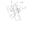
- FIG. 3 is a partial perspective view showing the fastening structure 100 of the mudguard according to the embodiment of the present disclosure.
- FIG. 4 is a sectional view taken along line IV-IV of FIG.
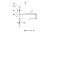
- the bolt 2 has a screw portion 21, a flat head 22, and a plate portion 23.
- the screw portion 21 is disposed on one end side in the axial direction (X1 direction).
- the flat head 22 is arranged on the other end side in the axial direction (X2 direction).
- the top surface 24 of the flat head 22 is flat. That is, the crown surface 24 is a plane orthogonal to the axial direction (X direction).
- the plate part 23 is arranged between the screw part 21 and the flat head 22.
- the plate portion 23 is welded to the seating surface 25 of the flat head 22 (the surface on the opposite side to the top surface 24 in the X direction).
- Known means such as projection welding is used for welding.
- a projection is provided on one of the flat head portion 22 and the plate portion 23.
- FIG. 4 shows the welded portion 26.
- the plate portion 23 has a function as a washer (flat washer).
- the plate portion 23 is fitted around the neck of the bolt 2 and is welded to the bearing surface 25 of the flat head 22.
- a standardized washer may be used as the plate portion 23, for example.
- a plate that matches the outer shape and thickness of the plate 23 may be selected from the standardized washers as the plate 23.
- the nut 3 is screwed into the screw portion 21. As shown in FIG. 2, the nut 3 is disposed in the X1 direction from the mudguards A and B. The flat head 22 and the plate 23 are arranged in the X2 direction from the mudguards A and B. Mudguards A and B are fastened by the nut 3 screwed into the screw portion 21, the flat head portion 22 and the plate portion 23.
- the mudguard A is provided with a counterbore A1 as shown in FIGS.
- the flat head portion 22 and the plate portion 23 are arranged so as to be fitted into the counterbore portion A1.
- the depth of the spot facing portion A1 is equal to the total thickness of the flat head portion 22 and the plate portion 23.
- the depth of the counterbore portion A1 is made equal to the combined thickness of the flat head portion 22 and the plate portion 23.
- the flat head 22 is directed toward the outer diameter portion of the tire 1.
- the radial clearance (X direction) between the flat head 22 and the tire 1 is made wider than the standardized radial clearance between the head of the bolt and the tire 1.
- the fastening member 200 can be provided in a place where the clearance between the tire 1 and the tire 1 is narrow.
- the plate portion 23 is pressed against the mudguards A and B. Since the plate portion 23 has an area larger than the area of the seating surface 25 of the flat head 22 and also has a function as a washer, the surface pressure on the mudguards A and B during fastening can be reduced. It becomes possible.
- the depth of the counterbore A1 is equal to the total thickness of the flat head 22 and the plate 23.
- the radial position (X direction) P3 of the top surface 24 of the flat head 22 is equal to the radial position P2 of the mudguard A.
- the radial clearance ⁇ between the tire 1 and the flat head 22 is substantially the same as the radial clearance ⁇ 1 between the tire 1 and the mudguard A.
- the flat head 22 does not protrude toward the tire 1 from the mudguard A, and the flat head 22 and the mudguard A smoothly continue in the outer circumferential direction of the tire 1. Can be reduced.
- the flat head 22 is not regarded as a projection, it is possible to satisfy, for example, laws and regulations concerning external projections.
- the fastening member 200 arranged near the tire 1 with the flat head 22 facing the tire 1 has been described.
- the present disclosure is not limited to this, and the flat head 22 is not limited thereto.
- the rotating body is not limited to the tire 1, but may be any rotating body disposed with a narrow clearance between the tire and the fastening member.
- a narrow clearance between the rotating member and the fastening member disposed in the housing may be used. Turbine.
- the plate portion 23 may be formed integrally with the flat head 22.
- the plate portion 23 may be formed integrally with the flat head 22.
- the plate portion 23 may be formed integrally with the screw portion 21 and the flat head portion 22.
- Known means such as laser processing is used for integral molding.
- the integral molding is employed, for example, when the outer shape and thickness of the plate portion 23 are special and a standardized washer cannot be used, that is, when a dedicated component is used. Since the plate portion 23 is formed integrally with the flat head portion 22, it is possible to prevent the plate portion 23 from being mixed up.
- the counterbore portion A1 is provided on the mudguard A.
- a clearance ⁇ in the radial direction (X direction) between the flat head 22 and the tire 1 can be sufficiently secured, In some cases, it is not necessary to provide the spot facing portion A1.
- the present disclosure is suitably used for a fastening member and a fastening structure that are required to be provided in a place where a clearance is narrow.
Landscapes
- Engineering & Computer Science (AREA)
- General Engineering & Computer Science (AREA)
- Mechanical Engineering (AREA)
- Body Structure For Vehicles (AREA)
- Bolts, Nuts, And Washers (AREA)
Abstract
クリアランスが狭い場所に設けることができる締結部材および締結構造を提供する。締結部材は、軸方向の一端側に配置されたネジ部と、軸方向の他端側に配置され、頭頂面が平らな平頭部と、ネジ部と平頭部との間に配置され、平頭部の座面の面積より広い面積を有するプレート部と、備える。たとえば、プレート部は、平頭部と一体的に構成されている。また、たとえば、プレート部は、平頭部に溶接されている。また、たとえば、プレート部は、平頭部と一体成形される。
Description
この開示は、締結部材および締結構造に関る。
従来、たとえば、タイヤの近傍位置に配置され、タイヤから跳ね上がる水滴や、小石などの飛散を防止するマッドガードを、ボルトおよびナットによって締結するマッドガードの締結構造がある(たとえば、特許文献1を参照)。
図1は、従来のマッドガードの締結構造の一例を示す図である。図1に、タイヤ1の外径部を一点鎖線で示す。図1に示すように、タイヤ1の近傍位置にマッドガードA,Bが配置されている。マッドガードA,Bは、ボルト2およびナット3によって相互に締結されている。
図1に示すように、タイヤ1とボルト2の頭部2a(締結部材の先端部)との間のクリアランスδが狭い場合、走行時の車両の揺れや懸架装置の伸縮、タイヤ1の膨張などによって、ボルト2の頭部2aがタイヤ1に当たるおそれがある。その結果、タイヤ1を傷める場合がある。
なお、締結部材として、たとえば、先端部を丸くした袋ナットのようなものを用いることは、先端部がタイヤ1に当たった場合にタイヤ1を傷めるのを抑える効果を奏する。しかしながら、締結部材の先端部がタイヤに当たるおそれがある状況を解消できるものではなく、クリアランスが狭い場所に設けることができる締結部材としては改善の余地がある。
本開示の目的は、クリアランスが狭い場所に設けることができる締結部材および締結構造を提供することである。
上記の目的を達成するため、本開示における締結部材は、
軸方向の一端側に配置されたネジ部と、
前記軸方向の他端側に配置され、頭頂面が平らな平頭部と、
前記ネジ部と前記平頭部との間に配置され、前記平頭部の座面の面積より広い面積を有するプレート部と、
備える。
軸方向の一端側に配置されたネジ部と、
前記軸方向の他端側に配置され、頭頂面が平らな平頭部と、
前記ネジ部と前記平頭部との間に配置され、前記平頭部の座面の面積より広い面積を有するプレート部と、
備える。
また、本開示における締結構造は、
上記締結部材を備えた締結構造であって、
前記締結部材は、前記平頭部を回転体側に向けて、前記回転体の近傍位置に配置される。
上記締結部材を備えた締結構造であって、
前記締結部材は、前記平頭部を回転体側に向けて、前記回転体の近傍位置に配置される。
本開示によれば、クリアランスが狭い場所に設けることができる。
以下、本開示の実施の形態について、図面を参照しながら説明する。
図2は、本開示の実施の形態に係るマッドガードの締結構造100を概略的に示す図である。図2にタイヤ1の外径部を一点鎖線で示す。なお、図1にはX軸が描かれている。以下の説明では、図1におけるタイヤ1の径方向を、X方向又は軸方向といい、タイヤ1の回転中心から離れる方向を、X1方向又は軸方向の一端側、タイヤ1の回転中心に近づく方向を、X2方向又は軸方向の他端側という。
図2は、本開示の実施の形態に係るマッドガードの締結構造100を概略的に示す図である。図2にタイヤ1の外径部を一点鎖線で示す。なお、図1にはX軸が描かれている。以下の説明では、図1におけるタイヤ1の径方向を、X方向又は軸方向といい、タイヤ1の回転中心から離れる方向を、X1方向又は軸方向の一端側、タイヤ1の回転中心に近づく方向を、X2方向又は軸方向の他端側という。
図2に示すように、マッドガードの締結構造100は、締結部材200によって、マッドガードA,Bを相互に締結するものである。マッドガードA,Bは、たとえば、樹脂材により成形されている。なお、マッドガードA,Bは、車体(不図示)側に装着されている。
締結部材200は、平頭部22(後述する)をタイヤ1の外径部側に向けて、タイヤ1の近傍位置に配置されている。締結部材200は、ボルト2およびナット3を備える。
図3は、本開示の実施の形態に係るマッドガードの締結構造100を示す部分斜視図である。図4は、図3のIV-IV線断面図である。
図4に示すように、ボルト2は、ネジ部21、平頭部22、および、プレート部23を有している。
ネジ部21は、軸方向の一端側(X1方向)に配置されている。
平頭部22は、軸方向の他端側(X2方向)に配置されている。平頭部22の頭頂面24は、平らである。つまり、頭頂面24は、軸方向(X方向)に対して直交する平面である。
プレート部23は、ネジ部21と平頭部22との間に配置されている。プレート部23は、平頭部22の座面25(頭頂面24とはX方向で反対側の面)に溶接されている。溶接には、プロジェクション溶接などの公知の手段が用いられる。この場合、平頭部22およびプレート部23のいずれか一方にプロジェクション(突起物)が設けられる。図4に、溶着部26を示す。
プレート部23は、ワッシャー(平座金)としての機能を有する。プレート部23は、ボルト2の首部に外嵌し、平頭部22の座面25に溶接される。プレート部23として、たとえば、規格化されたワッシャーを用いてもよい。換言すれば、規格化されたワッシャーの中から、プレート部23の外形形状や厚さと一致するものを、プレート部23として選択すればよい。
ナット3は、ネジ部21に螺合する。図2に示すように、ナット3は、マッドガードA,BよりX1方向に配置されている。平頭部22およびプレート部23は、マッドガードA,BよりX2方向に配置されている。ネジ部21に螺合するナット3と、平頭部22およびプレート部23とにより、マッドガードA,Bが締結される。
マッドガードAには、図2および図3に示すように、座ぐり部A1が設けられている。座ぐり部A1に、平頭部22およびプレート部23が嵌め込まれるように配置されている。座ぐり部A1の深さは、平頭部22およびプレート部23を合わせた厚さと等しい。たとえば、プレート部23の厚さを適宜変更することにより、座ぐり部A1の深さと、平頭部22およびプレート部23を合わせた厚さとを等しくする。これにより、平頭部22の厚さが決められているボルト2に規格品を用いることが可能となる。
本実施の形態に係る締結構造100によれば、平頭部22は、タイヤ1の外径部側に向けられる。これにより、平頭部22とタイヤ1との間の径方向(X方向)のクリアランスδを、規格化されたボルトの頭部とタイヤ1との間の径方向のクリアランスに比べて、広くすることができ、たとえば、走行時に車両が揺れても、平頭部22がタイヤ1に当たらないようになるため、タイヤ1との間のクリアランスが狭い場所に、締結部材200を設けることが可能となる。
また、本実施の形態に係る締結構造100によれば、プレート部23は、マッドガードA,Bに圧接されている。プレート部23は、平頭部22の座面25の面積より広い面積を有するため、また、ワッシャーとしての機能を有しているため、締結時におけるマッドガードA,Bに対する面圧を低下させることが可能となる。
また、本実施の形態に係る締結構造100によれば、座ぐり部A1の深さは、平頭部22およびプレート部23を合わせた厚さと等しい。換言すれば、平頭部22の頭頂面24の径方向(X方向)の位置P3と、マッドガードAの径方向の位置P2とは、等しい。これにより、タイヤ1と平頭部22との間の径方向のクリアランスδと、タイヤ1とマッドガードAとの間の径方向のクリアランスδ1とは、ほぼ同じになる。その結果、平頭部22がマッドガードAよりタイヤ1側に突出しないで、平頭部22とマッドガードAとがタイヤ1の外周方向に対して滑らかに連続するため、走行中にタイヤ1とマッドガードAとの間の隙間に流れる空気抵抗を低減させることができる。また、平頭部22が突起としてみなされないため、たとえば、外部突起に係る法規制を満たすことが可能となる。
また、タイヤ1の交換を行うことで、タイヤ1の外径が大きくなった場合であっても、タイヤ1と平頭部22と間の径方向のクリアランスδを広くしているため、平頭部22がタイヤ1に当たらないようにすることが可能となる。
なお、上記実施の形態においては、平頭部22をタイヤ1側に向けて、タイヤ1の近傍位置に配置される締結部材200について説明したが、本開示はこれに限らず、平頭部22を回転体側に向けて、回転体の近傍位置に配置される締結部材に適用できる。回転体としては、タイヤ1に限定されるものではなく、締結部材との間に狭いクリアランスで配置される回転体であればよく、たとえば、ハウジング内に配置される締結部材との間に狭いクリアランスで配置されるタービンである。
また、上記実施の形態では、プレート部23は、平頭部22と一体的に構成されていればよい。例えば、プレート部23は、平頭部22と一体成形されてもよい。また、プレート部23は、ネジ部21および平頭部22と一体成形されてもよい。一体成形には、レーザー加工などの公知の手段が用いられる。一体成形は、たとえば、プレート部23の外形形状や厚さが特殊であって、規格化されたワッシャーを利用できない場合、つまり、専用部品の場合に採用される。プレート部23が平頭部22と一体的に構成されることで、プレート部23の取り違えを防止することができる。
また、上記実施の形態では、マッドガードAに座ぐり部A1を設けたが、平頭部22とタイヤ1との間の径方向(X方向)のクリアランスδを十分に確保することができる場合、座ぐり部A1を設けなくてもよい場合がある。
その他、上記実施の形態は、何れも本開示の実施するにあたっての具体化の一例を示したものに過ぎず、これらによって本開示の技術的範囲が限定的に解釈されてはならないものである。すなわち、本開示はその要旨、またはその主要な特徴から逸脱することなく、様々な形で実施することができる。
本開示は、クリアランスが狭い場所に設けることが要求される締結部材および締結構造に好適に利用される。
本出願は、2018年9月13日付けで出願された日本国特許出願(特願2018-171661)に基づくものであり、その内容はここに参照として取り込まれる。
δ,δ1 クリアランス
1 タイヤ
2 ボルト
3 ナット
21 ネジ部
22 平頭部
23 プレート部
24 頭頂面
25 座面
26 溶着部
100 締結構造
200 締結部材
1 タイヤ
2 ボルト
3 ナット
21 ネジ部
22 平頭部
23 プレート部
24 頭頂面
25 座面
26 溶着部
100 締結構造
200 締結部材
Claims (6)
- 軸方向の一端側に配置されたネジ部と、
前記軸方向の他端側に配置され、頭頂面が平らな平頭部と、
前記ネジ部と前記平頭部との間に配置され、前記平頭部の座面の面積より広い面積を有するプレート部と、
を備える、
締結部材。 - 前記プレート部は、前記平頭部と一体的に構成されている、
請求項1に記載の締結部材。 - 前記プレート部は、前記平頭部に溶接されている、
請求項2に記載の締結部材。 - 前記プレート部は、前記平頭部と一体成形される、
請求項2に記載の締結部材。 - 前記プレート部は、ワッシャーとしての機能を有する、
請求項1から4のいずれか一項に記載の締結部材。 - 請求項1から5のいずれか一項に記載の締結部材を備えた締結構造であって、
前記締結部材は、前記平頭部を回転体側に向けて、前記回転体の近傍位置に配置される、
締結構造。
Applications Claiming Priority (2)
| Application Number | Priority Date | Filing Date | Title |
|---|---|---|---|
| JP2018-171661 | 2018-09-13 | ||
| JP2018171661A JP2020041668A (ja) | 2018-09-13 | 2018-09-13 | 締結部材および締結構造 |
Publications (1)
| Publication Number | Publication Date |
|---|---|
| WO2020054831A1 true WO2020054831A1 (ja) | 2020-03-19 |
Family
ID=69776816
Family Applications (1)
| Application Number | Title | Priority Date | Filing Date |
|---|---|---|---|
| PCT/JP2019/036020 Ceased WO2020054831A1 (ja) | 2018-09-13 | 2019-09-13 | 締結部材および締結構造 |
Country Status (2)
| Country | Link |
|---|---|
| JP (1) | JP2020041668A (ja) |
| WO (1) | WO2020054831A1 (ja) |
Citations (3)
| Publication number | Priority date | Publication date | Assignee | Title |
|---|---|---|---|---|
| JPS56124065U (ja) * | 1980-02-22 | 1981-09-21 | ||
| JP2017219062A (ja) * | 2016-06-03 | 2017-12-14 | 三菱電機株式会社 | ボルト締結構造および屋外設置筐体 |
| JP3214339U (ja) * | 2017-10-23 | 2018-01-11 | 株式会社協栄製作所 | フランジボルトと皿ばねナットからなる連結具 |
-
2018
- 2018-09-13 JP JP2018171661A patent/JP2020041668A/ja active Pending
-
2019
- 2019-09-13 WO PCT/JP2019/036020 patent/WO2020054831A1/ja not_active Ceased
Patent Citations (3)
| Publication number | Priority date | Publication date | Assignee | Title |
|---|---|---|---|---|
| JPS56124065U (ja) * | 1980-02-22 | 1981-09-21 | ||
| JP2017219062A (ja) * | 2016-06-03 | 2017-12-14 | 三菱電機株式会社 | ボルト締結構造および屋外設置筐体 |
| JP3214339U (ja) * | 2017-10-23 | 2018-01-11 | 株式会社協栄製作所 | フランジボルトと皿ばねナットからなる連結具 |
Also Published As
| Publication number | Publication date |
|---|---|
| JP2020041668A (ja) | 2020-03-19 |
Similar Documents
| Publication | Publication Date | Title |
|---|---|---|
| US9809261B2 (en) | Vehicle body lateral structure | |
| EP3246180B1 (en) | Non-pneumatic wheel | |
| US6575536B2 (en) | Bolt structure for fastening a truck wheel | |
| KR101819143B1 (ko) | 베어링이 구비된 일체형 더스트 커버 | |
| US10486629B2 (en) | Vehicle front portion structure | |
| US10293858B2 (en) | Vehicle substructure | |
| KR101601470B1 (ko) | 공력 개선 구조를 갖는 스포크 휠 | |
| JP2020041668A (ja) | 締結部材および締結構造 | |
| JP6653566B2 (ja) | フランジの固定構造 | |
| JP2017219052A (ja) | ボルト締結構造 | |
| JP7363827B2 (ja) | 脱輪防止構造および車輪装置 | |
| JP6376089B2 (ja) | フューエルインレットパイプ固定構造 | |
| JP7017332B2 (ja) | ストラットマウント | |
| WO2021020053A1 (ja) | 車両用ホイール | |
| JP6291428B2 (ja) | クランプインバルブ付きホイール | |
| JP2008196515A (ja) | ポップナット | |
| JP6197396B2 (ja) | 車両用部品 | |
| JP2005172033A (ja) | ナット | |
| JP3169950U (ja) | レンチ用ソケット | |
| JP2021046885A (ja) | 固定用構造 | |
| US20080018169A1 (en) | Wheel for a vehicle | |
| JP2009274465A (ja) | 車両の脱輪防止具 | |
| JP5183929B2 (ja) | アンダーカバーの組み付け構造 | |
| JPS6333008B2 (ja) | ||
| JP2008014361A (ja) | 部材のビス止め構造 |
Legal Events
| Date | Code | Title | Description |
|---|---|---|---|
| 121 | Ep: the epo has been informed by wipo that ep was designated in this application |
Ref document number: 19860729 Country of ref document: EP Kind code of ref document: A1 |
|
| NENP | Non-entry into the national phase |
Ref country code: DE |
|
| 122 | Ep: pct application non-entry in european phase |
Ref document number: 19860729 Country of ref document: EP Kind code of ref document: A1 |