WO2020054677A1 - 乗物用シート - Google Patents
乗物用シート Download PDFInfo
- Publication number
- WO2020054677A1 WO2020054677A1 PCT/JP2019/035409 JP2019035409W WO2020054677A1 WO 2020054677 A1 WO2020054677 A1 WO 2020054677A1 JP 2019035409 W JP2019035409 W JP 2019035409W WO 2020054677 A1 WO2020054677 A1 WO 2020054677A1
- Authority
- WO
- WIPO (PCT)
- Prior art keywords
- seat
- frame
- vehicle seat
- bracket
- mounting bracket
- Prior art date
- Legal status (The legal status is an assumption and is not a legal conclusion. Google has not performed a legal analysis and makes no representation as to the accuracy of the status listed.)
- Ceased
Links
Images








Classifications
-
- B—PERFORMING OPERATIONS; TRANSPORTING
- B60—VEHICLES IN GENERAL
- B60N—SEATS SPECIALLY ADAPTED FOR VEHICLES; VEHICLE PASSENGER ACCOMMODATION NOT OTHERWISE PROVIDED FOR
- B60N2/00—Seats specially adapted for vehicles; Arrangement or mounting of seats in vehicles
- B60N2/24—Seats specially adapted for vehicles; Arrangement or mounting of seats in vehicles for particular purposes or particular vehicles
- B60N2/30—Non-dismountable or dismountable seats storable in a non-use position, e.g. foldable spare seats
- B60N2/3002—Non-dismountable or dismountable seats storable in a non-use position, e.g. foldable spare seats back-rest movements
- B60N2/3004—Non-dismountable or dismountable seats storable in a non-use position, e.g. foldable spare seats back-rest movements by rotation only
- B60N2/3009—Non-dismountable or dismountable seats storable in a non-use position, e.g. foldable spare seats back-rest movements by rotation only about transversal axis
- B60N2/3011—Non-dismountable or dismountable seats storable in a non-use position, e.g. foldable spare seats back-rest movements by rotation only about transversal axis the back-rest being hinged on the cushion, e.g. "portefeuille movement"
-
- B—PERFORMING OPERATIONS; TRANSPORTING
- B60—VEHICLES IN GENERAL
- B60N—SEATS SPECIALLY ADAPTED FOR VEHICLES; VEHICLE PASSENGER ACCOMMODATION NOT OTHERWISE PROVIDED FOR
- B60N2/00—Seats specially adapted for vehicles; Arrangement or mounting of seats in vehicles
- B60N2/64—Back-rests or cushions
-
- B—PERFORMING OPERATIONS; TRANSPORTING
- B60—VEHICLES IN GENERAL
- B60N—SEATS SPECIALLY ADAPTED FOR VEHICLES; VEHICLE PASSENGER ACCOMMODATION NOT OTHERWISE PROVIDED FOR
- B60N2/00—Seats specially adapted for vehicles; Arrangement or mounting of seats in vehicles
- B60N2/68—Seat frames
-
- B—PERFORMING OPERATIONS; TRANSPORTING
- B60—VEHICLES IN GENERAL
- B60N—SEATS SPECIALLY ADAPTED FOR VEHICLES; VEHICLE PASSENGER ACCOMMODATION NOT OTHERWISE PROVIDED FOR
- B60N2/00—Seats specially adapted for vehicles; Arrangement or mounting of seats in vehicles
- B60N2/90—Details or parts not otherwise provided for
- B60N2/919—Positioning and locking mechanisms
- B60N2002/952—Positioning and locking mechanisms characterised by details of the locking system
Definitions
- the present invention relates to a vehicle seat having a seat back that can be tilted with respect to a seat cushion, and particularly to a vehicle including a lock unit that engages with an engaged portion provided on a vehicle body to lock the tilt of the seat back.
- the present invention relates to a vehicle seat.
- Patent Literature 1 discloses a seatback frame in which a bracket is provided at a side corner of a frame member formed by bending a pipe into a frame shape, and a lock unit that is detachably attached to a striker supported by a vehicle body. Is described. When the occupant is seated, the lock unit is engaged with the striker, and the bracket and the seat back frame are fixed to the vehicle body.
- the present invention has been made in view of the above problems, and an object of the present invention is to improve strength around a side frame to which a lock unit is attached in a seat back frame and stably support the lock unit. It is to provide a possible vehicle seat.
- a vehicle seat including a seat back which can be tilted with respect to a seat cushion, wherein the seat back includes a seat back frame and a cover provided on a vehicle body.
- a lock unit that engages with an engaging portion to lock the tilt of the seat back frame, wherein the seat back frame includes a side frame extending in a vertical direction of the vehicle seat;
- a mounting bracket attached to the outside in the width direction of the vehicle seat, wherein the lock unit is attached to an outer side surface of the mounting bracket in the width direction of the vehicle seat, and the side frame and the The problem is solved by the mounting bracket being connected by a reinforcing bracket.
- the strength around the side frame to which the lock unit is attached is improved by the reinforcing bracket, so that the lock unit can be stably supported.
- the mounting bracket includes a front surface and a rear surface in a front-rear direction of the vehicle seat, the front surface and the rear surface are connected by the outer surface, and the reinforcing bracket includes the side frame. And the front surface of the mounting bracket.
- the rear surface of the mounting bracket has a protrusion that projects forward in the front-rear direction of the vehicle seat, and the mounting bracket is attached to the side frame at the protrusion. Good.
- the lock unit can be more stably supported.
- the mounting bracket may include an opening that straddles the rear surface and the outer surface.
- the mounting bracket includes an upper surface and a lower surface in a vertical direction of the vehicle seat, the upper surface includes a first concave portion that engages with the side frame, and the lower surface includes the side surface. It is good to have a 2nd crevice engaged with a frame, and the above-mentioned attachment bracket is attached to the side frame in the 1st crevice and the 2nd crevice. In the above configuration, since the mounting bracket is mounted on the side frame in the first concave portion on the upper surface and the second concave portion on the lower surface in the vertical direction of the seat, mounting of the mounting bracket on the side frame is further stabilized. .
- the mounting bracket may include a slit on each of the upper surface and the lower surface.
- the upper surface and the lower surface of the mounting bracket are each provided with a slit, it is possible to form the upper surface and the lower surface having the slit by bending a plate material or the like. Work becomes easy.
- the reinforcing bracket includes a front end and a rear end in the front-rear direction of the vehicle seat, and a reinforcing bead extending between the front end and the rear end is formed. Good. In the above configuration, by providing the reinforcing beads, the rigidity of the reinforcing bracket can be improved.
- the reinforcing bead has an upper reinforcing bead at an upper end portion of the reinforcing bracket, a lower reinforcing bead at a lower end portion of the reinforcing bracket, and in a front-rear direction of the vehicle seat, It is preferable that the distance between the upper reinforcing bead and the lower reinforcing bead increases from the front to the rear.
- the reinforcing bracket since the reinforcing bracket has the upper reinforcing bead and the lower reinforcing bead that increase in distance as going from the front to the rear, it is possible to improve the strength of the vehicle seat against impact applied from the front-rear direction. Become.
- an unlocking member for unlocking the tilt of the seat back frame a support bracket for supporting the unlocking member, and a wire member attached to the support bracket, the wire member includes One end is attached to the outer surface of the mounting bracket, and the other end is attached to the seat back frame.
- the support bracket includes a front portion and a rear portion in a front-rear direction of the vehicle seat, the front portion is attached to the mounting bracket, and the rear portion is connected to the wire member. It should be attached. With the above configuration, the lock release member can be stably fixed.
- the vehicle seat of the present invention it is possible to stably support the lock unit by improving the strength around the side frame to which the lock unit is attached by the reinforcing bracket. Further, according to the vehicle seat of the present invention, by appropriately improving the strength of the mounting bracket, it is possible to more stably support the lock unit. According to the vehicle seat of the present invention, since the mounting bracket is stably mounted on the side frame, the lock unit can be more stably supported. Further, according to the vehicle seat of the present invention, it is possible to secure the outer surface on which the lock unit is to be mounted, and to reduce the weight without reducing the rigidity of the mounting bracket.
- the mounting bracket since the mounting bracket is mounted on the side frame in the first concave portion on the upper surface and the second concave portion on the lower surface in the vertical direction of the seat, the mounting bracket can be mounted on the side frame. It will be more stable. Further, according to the vehicle seat of the present invention, since the upper surface and the lower surface of the mounting bracket are each provided with a slit, it is possible to form the upper surface and the lower surface having the slit by bending a plate material or the like, The work at the time of forming the mounting bracket becomes easy. Further, according to the vehicle seat of the present invention, it is possible to improve the rigidity of the reinforcing bracket by providing the reinforcing bead.
- the reinforcing bracket has the upper reinforcing bead and the lower reinforcing bead that increase in distance from the front to the rear, the strength of the vehicle seat against impact applied from the front-rear direction is provided. Can be improved.
- the lock release member can be fixed by a simple structure. Further, according to the vehicle seat of the present invention, the unlocking member can be stably fixed.
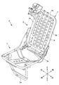
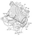
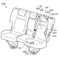
- FIG. 1 is an external view of a vehicle seat according to a first embodiment of the present invention.
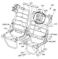
- 1 is an external view of a seat frame of a vehicle seat according to a first embodiment of the present invention.
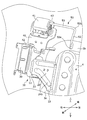
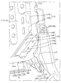
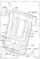
- FIG. 2 is a partially enlarged view showing a structure around a lock unit of the seat frame according to the first embodiment of the present invention.
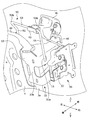
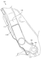
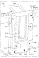
- FIG. 2 is a partially enlarged view showing a structure around a lock unit of the seat frame according to the first embodiment of the present invention.
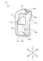
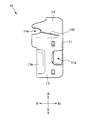
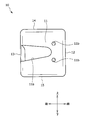
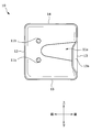
- 1 is an external view of a vehicle seat mounting bracket according to a first embodiment of the present invention.
- 1 is an external view of a vehicle seat mounting bracket according to a first embodiment of the present invention.
- 1 is an external view of a vehicle seat mounting bracket according to a first embodiment of the present invention.
- 1 is an external view of a vehicle seat mounting bracket according to a first embodiment of the present invention.
- 1 is an external view of a vehicle seat mounting bracket according to a first embodiment of the present invention.
- 1 is an external view of a vehicle seat mounting bracket according to a first embodiment of the present invention.
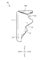
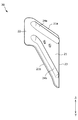
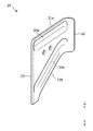
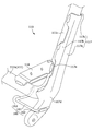
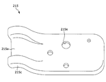
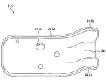
- 1 is an external view of a reinforcing bracket for a vehicle seat according to a first embodiment of the present invention.
- 1 is an external view of a reinforcing bracket for a vehicle seat according to a first embodiment of the present invention.
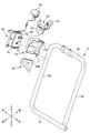
- It is a partial exploded view of a seat frame of a vehicle seat according to a first embodiment of the present invention.
- It is an outline view of a seat frame of a vehicular seat according to a modification of the first embodiment of the present invention.
- FIG. 6 is a partially enlarged view showing a structure around a lock unit of a seat frame according to a modification of the first embodiment of the present invention. It is an external appearance perspective view of the vehicle seat concerning a 2nd embodiment of the present invention. It is an external appearance perspective view of the seat frame of the vehicle seat which concerns on 2nd Embodiment of this invention. It is a perspective view of a seat frame concerning a 2nd embodiment of the present invention, and is an enlarged drawing of an important section. It is a front view of the seat frame concerning a 2nd embodiment of the present invention, and is an enlarged drawing of an important section.
- FIG. 21 is a sectional view taken along the line VII-VII of FIG. 20. It is an external appearance perspective view of the vehicle seat concerning a 3rd embodiment of the present invention. It is an external appearance perspective view of the seat frame of the vehicle seat concerning a 3rd embodiment of the present invention. It is a front view of the back frame of the vehicular seat concerning a 3rd embodiment of the present invention, and an important section enlarged drawing.
- FIG. 13 is a perspective view of a back frame of a vehicle seat according to a third embodiment of the present invention as viewed from the rear of the seat, illustrating a state where a panel bracket and a mounting bracket are assembled. It is a front view of the mounting bracket of the vehicle seat which concerns on 3rd Embodiment of this invention. It is a rear view of the mounting bracket of the vehicle seat which concerns on 3rd Embodiment of this invention.
- FIG. 27 is a sectional view taken along line VI-VI of FIG. 26.
- a vehicle seat according to a first embodiment (hereinafter, this embodiment) of the present invention will be described with reference to FIGS. 1 to 16 by taking a vehicle seat mounted on a vehicle as an example.
- each direction is defined as shown in FIG.
- the “front-rear direction” refers to the front-rear direction when viewed from the occupant of the vehicle seat, and is a direction that matches the traveling direction of the vehicle.
- the “seat width direction” means the width direction of the vehicle seat, and coincides with the left-right direction when viewed from the occupant of the vehicle seat.
- the “vertical direction” means the height direction of the vehicle seat, and coincides with the vertical direction when the vehicle seat is viewed from the front.
- the vehicle seat S of the present embodiment is, for example, a rear seat corresponding to a rear right seat of the vehicle.
- the vehicle seat S according to the present embodiment has the appearance illustrated in FIG. In FIG. 1, a part of the vehicle seat S is illustrated in a configuration in which a trim cover is removed for convenience of illustration.
- the vehicle seat S is provided on a seat cushion S1 serving as a seating portion for supporting the buttocks of a seated person, a seatback S2 serving as a backrest portion for supporting the back of the seated person, and an upper portion of the seatback S2.
- a seat cushion S1 serving as a seating portion for supporting the buttocks of a seated person
- a seatback S2 serving as a backrest portion for supporting the back of the seated person
- the seat back S2 is rotatably supported by a support base (not shown).
- the vehicle seat S can be shifted from a use state in which a passenger can sit down to a storage state in which the seat cushion S1, the seat back S2, and the headrest S3 (hereinafter, referred to as a seat body) are stored on a storage floor.
- the vehicle seat S is tilted and folded in a direction in which the seat back S2 and the headrest S3 approach the seat cushion S1 by pulling the operation lever (an unlocking member 41 described later) from the use state. Then, the state is switched to the storage state stored in the storage floor. In addition, the occupant manually returns the seat body upward from the stored state to return to the use state.
- the seat cushion S1 is configured by placing the cushion pad S11 on the seat cushion frame 1 serving as a skeleton shown in FIG. 2, and further covering the cushion pad S11 with a trim cover S12.
- the seat back S2 is configured by placing a cushion pad S21 on the seat back frame 2 serving as a skeleton shown in FIG. 2 and covering the cushion pad S21 with a trim cover S22.
- the headrest S3 is formed by arranging a cushion pad S31 on a core material (not shown) and covering with a trim cover S32.
- the cushion pads S11, S21, and S31 are made of a cushion material having elasticity such as urethane foam, and the trim covers S12, S22, and S32 are made of synthetic leather, cloth, or the like, and are formed by sewing a plurality of skin materials. .
- FIG. 2 illustrates a seat frame F of a right seat of the vehicle seat S illustrated in FIG. 1.
- the seat frame F mainly includes a seat cushion frame 1 and a seat back frame 2.
- the seat cushion frame 1 forms a skeleton of a seating portion of the vehicle seat S
- the seat back frame 2 forms a skeleton of a backrest portion of the vehicle seat S.
- the seat cushion frame 1 has a rectangular frame-like outer shape when viewed from above.
- the main components of the seat cushion frame 1 are a side frame forming an end in the seat width direction and a pan frame forming a front end of the seat cushion frame 1.
- the seat cushion frame 1 includes a support leg 1a, and in a use state in which an occupant can sit down, as shown in FIG. 1, the support leg 1a is engaged with and fixed to a support base (not shown).
- the seat back frame 2 includes a pipe frame 3 and a back panel 4 provided on the rear surface of the seat of the pipe frame 3.
- the pipe frame 3 is a substantially rectangular frame formed by bending a metal pipe member. As shown in FIG. 2, the pipe frame 3 is disposed apart from each other and extends in the longitudinal direction (the sheet vertical direction). It comprises a pair of side frames 3a, an upper frame 3b connecting the upper ends of the pair of side frames 3a, and a lower frame 3c connecting the lower ends.
- a substantially flat surface is formed on the front surface of the upper frame 3b in the sheet width direction.
- a pair of pillar support portions for supporting a headrest pillar are attached to the portion where the substantially flat surface is formed.
- a headrest pillar (not shown) is inserted into the pillar support, and a headrest S3 is attached.
- the back panel 4 is a metal panel member having a substantially rectangular shape.
- the left and right ends of the back panel 4 in the seat width direction are attached to the left and right side frames 3a of the pipe frame 3 by welding.
- the upper part and the lower part of the back panel 4 in the seat vertical direction are attached to the upper frame 3b and the lower frame 3c by welding, respectively.
- the vehicle seat S includes a lock unit 30 that locks the tilt of the seat back frame 2 (seat back S2).
- the attachment of the lock unit 30 to the seat frame F will be described below with reference to FIGS.
- FIG. 3 and 4 are partially enlarged views showing the structure around the lock unit 30 attached to the seat frame F.
- FIG. 3 shows the structure around the lock unit 30 when viewed from the front of the seat.
- FIG. 4 shows the structure around the lock unit 30 when viewed from the rear of the seat.
- a mounting bracket 10 is mounted on the outer side of the side frame 3 a in the seat width direction, and a lock unit 30 is mounted on an outer surface 11 of the mounting bracket 10 in the seat width direction.
- the lock unit 30 includes a lock piece 33, and the lock piece 33 is engaged with an engaged portion (strike) (not shown) provided on the vehicle body, so that the seat back frame 2 (seat back) is provided. The tilting of S2) is locked.
- FIGS. 3 and 4 the side frame 3 a and the mounting bracket 10 are connected by the reinforcing bracket 20.
- An unlocking member 41 (operation lever) for unlocking the tilt of the seat back frame 2 (seat back S2) is rotatably supported by the support bracket 40.
- a front part 42 is attached to the mounting bracket 10 and a rear part 43 is attached to a wire member 50 in the seat front-rear direction.
- a hatched portion indicates a welding mark.
- FIGS. 5 is an external view of the mounting bracket 10
- FIG. 6 is an external view of the mounting bracket 10 as viewed from the upper front
- FIG. 7 is an external view of the mounting bracket 10 as viewed from the lower front
- FIG. FIG. 9 is an external view of the mounting bracket 10 viewed from the upper rear side
- FIG. 9 is an external view of the mounting bracket 10 viewed from the outside in the seat width direction
- FIG. 10 is an external view of the mounting bracket 10 viewed from the inside in the seat width direction.
- FIG. 10 is an external view of the mounting bracket 10 viewed from the inside in the seat width direction.
- the mounting bracket 10 includes an outer surface 11 arranged in the seat width direction, a front surface 12 and a rear surface 13 arranged in the seat front-rear direction, and an upper surface 14 arranged in the seat up-down direction. And a lower surface 15.
- the outer side surface 11 connects the front surface 12 and the rear surface 13 in the seat front-back direction, and connects the upper surface 14 and the lower surface 15 in the seat up-down direction.
- the mounting bracket 10 has a substantially box-like shape as shown in FIG.
- the outer surface 11 of the mounting bracket 10 has an opening 11 a extending over the rear surface 13. Further, the outer side surface 11 has two mounting holes 11b used for mounting the lock unit 30 at a position closer to the front surface 12 than the rear surface 13 in the seat front-rear direction and in the seat up-down direction.
- the rear surface 13 of the mounting bracket 10 is formed with a convex portion 13 a protruding forward in the seat front-rear direction.
- the rear surface 13 of the mounting bracket 10 is formed with a convex portion 13a protruding in a direction toward the outer side surface 11.
- the mounting bracket 10 is mounted on the side frame 3a by welding at the projection 13a.
- the upper surface 14 of the mounting bracket 10 has a concave portion 14a (first concave portion), and the lower surface 15 has a concave portion 15a (second concave portion).
- the upper surface 14 of the mounting bracket 10 has an outer shape that curves from the inside in the seat width direction toward the outside (in other words, the direction toward the outside surface 11).
- the provided concave portion 14a is formed.
- the lower surface 15 of the mounting bracket 10 has a concave portion 15a having an outer shape that curves from the inside in the seat width direction to the outside (in other words, the direction toward the outside surface 11). Have been.
- the mounting bracket 10 is welded to the side frame 3 a in the concave portion 14 a of the upper surface 14.
- the mounting bracket 10 is similarly welded to the side frame 3a in the recess 15a on the lower surface 15. Since the mounting bracket 10 is mounted to the side frame 3a at two locations in the seat vertical direction, that is, the concave portion 14a of the upper surface 14 and the concave portion 15a of the lower surface 15, the mounting bracket 10 can be securely mounted to the side frame 3a. It has become.
- the mounting bracket 10 has a slit 14b on the upper surface 14 and a slit 15b on the lower surface 15.
- the slit 14b is formed on the upper surface 14 so as to extend from a corner adjacent to the outer surface 11 and the rear surface 13 toward the recess 14a.
- the slit 15b is formed on the lower surface 15 so as to extend from a corner adjacent to the outer surface 11 and the rear surface 13 toward the recess 15a.
- the mounting bracket 10 is formed by punching and bending one metal plate. At this time, since the upper surface 14 and the lower surface 15 of the mounting bracket 10 have the slits 14b and 15b, respectively, it is possible to form the upper surface 14 and the lower surface 15 having the slits 14b and 15b by bending a metal plate or the like. Therefore, the operation at the time of forming the mounting bracket 10 becomes easy. Similarly, the mounting bracket 10 has an opening 11 a formed at a position straddling the outer side surface 11 and the rear surface 13, so that the operation at the time of forming the mounting bracket 10 is easy, and at the same time, the outside of mounting the lock unit 30. It is possible to reduce the weight while securing the side surface 11 without reducing the rigidity.
- FIG. 11 is an external view of the reinforcing bracket 20 as viewed from the front
- FIG. 12 is an external view of the reinforcing bracket 20 as viewed from the rear.
- the reinforcing bracket 20 is formed of a metal curved plate-like member, and has an upper end portion 21a and a lower end portion 21b which are arranged in the seat up-down direction when attached to the seat back frame 2 of the vehicle seat S.
- the vehicle includes a base 21 and a front end 22 and a rear end 23 which are formed by bending from the base 21 in the front-rear direction of the seat. As shown in FIGS. 11 and 12, the length of the front end 22 is shorter than the length of the rear end 23 in the vertical direction of the sheet.
- the reinforcing bracket 20 is formed with reinforcing beads 24 a and 24 b extending between the front end 22 and the rear end 23. Specifically, a reinforcing bead 24a (upper reinforcing bead) is formed near the upper end 21a of the reinforcing bracket 20, and a reinforcing bead 24b (lower reinforcing bead) is formed near the lower end 21b. I have.
- the reinforcing beads 24a and 24b By providing the reinforcing beads 24a and 24b, the rigidity of the reinforcing bracket 20 is improved. As shown in FIG. 3, when the reinforcing bracket 20 is attached to the seat back frame 2, the reinforcing beads 24 a and 24 b are arranged so as to protrude forward from the base 21.
- the reinforcing beads 24a and 24b have an upper reinforcing bead (a reinforcing bead 24a) at the upper end 21a of the reinforcing bracket 20 and a lower reinforcing bead (the lower bead 24) at the lower end 21b of the reinforcing bracket 20.
- the distance between the upper reinforcing bead (the reinforcing bead 24a) and the lower reinforcing bead (the reinforcing bead 24b) increases in the front-rear direction of the vehicle seat S.
- the reinforcing bracket 20 has the upper reinforcing bead (reinforcement bead 24a) and the lower reinforcement bead (reinforcement bead 24b) whose intervals increase from the front to the rear, an impact applied from the front-back direction of the vehicle seat S is provided. Can be improved.
- the distance between the reinforcing beads 24a and the reinforcing beads 24b increases from the front to the rear in the front-back direction of the seat. In other words, the distance between the reinforcing bead 24a and the reinforcing bead 24b increases from the front end 22 to the rear end 23 of the reinforcing bracket 20.
- the reinforcing bracket 20 has a front end 22 welded to the front surface 12 of the mounting bracket 10 and a rear end 23 attached to the side frame 3 a on the inner side in the seat width direction. Installed by welding.
- the reinforcing bracket 20 the strength around the side frame 3a to which the mounting bracket 10 is mounted is improved, so that the lock unit 30 can be stably supported by the mounting bracket 10.
- the reinforcing bracket 20 connects the side frame 3a to the front surface 12 of the mounting bracket 10, and the lock unit 30 is further stabilized by appropriately improving the strength of the mounting bracket 10 mounted on the side frame 3a. It becomes possible to support.
- FIG. 13 is a partially exploded view of the seat frame F. As shown in FIG. 13, the lock unit 30 has an inner side surface 31 on the inner side in the seat width direction. 32 are formed. The lock unit 30 is connected to a lock release member 41 that is rotatably supported by the support bracket 40.
- the lock unit 30 is a known lock unit including a spring member (not shown) and a lock piece 33 (FIG. 4) connected to the spring member, and a striker (not shown) in which the lock piece 33 is supported by the vehicle body.
- the tilting of the seat back frame 2 is locked by engaging with the engaging portion).
- the unlocking member 41 When the occupant rotates the unlocking member 41, the spring member included in the lock unit 30 is extended, and the engagement between the lock piece 33 and the striker is released, so that the tilting lock of the seat back frame 2 is released. Is done.
- the mounting hole 32 provided on the inner side surface 31 of the lock unit 30 is aligned with the mounting hole 11b provided on the outer side surface 11 of the mounting bracket 10, and a not-shown fastening member (for example, a bolt) is passed through.
- a not-shown fastening member for example, a bolt
- the wire member 50 is formed by bending a wire, and includes a first extension portion 51 and a second extension portion 52 extending in the sheet up-down direction, and a first extension portion. And a connecting portion 53 that connects the extending portion 51 and the second extending portion 52.
- the first end portion 51 a of the first extension portion 51 is welded and attached to the outer surface 11 of the mounting bracket 10, and the second end portion of the second extension portion 52. 52a is attached by welding to the upper frame 3b.
- the wire is bent at the first bent portion 51b, which is the end of the first extension portion 51 opposite to the first end 51a, and the connecting portion 53 is connected.
- the wire is bent at the second bent portion 52b, which is the end of the second extending portion 52 opposite to the second end 52a, and the connecting portion 53 is connected.
- the wire member 50 has the first end 51a attached to the outer surface 11 of the mounting bracket 10 and the second end 52a attached to the seat back frame 2 (upper frame 3b).
- the support bracket 40 and the lock release member 41 are fixed by a simple structure. Further, in the support bracket 40, in the seat front-rear direction, the front portion 42 is attached to the front surface 12 of the mounting bracket 10 by welding, and the rear portion 43 is attached to the connecting portion 53 of the wire member 50. 41 can be stably supported.
- the vehicle seat S includes the seat back S2 that can tilt with respect to the seat cushion S1, and the seat back S2 includes the seat back frame 2, A lock unit 30 that engages with an engaged portion (strike) provided on the vehicle body to lock the tilt of the seat back frame 2, wherein the seat back frame 2 extends in the up-down direction of the vehicle seat S
- the mounting bracket 10 attached to the outside of the side frame 3a in the width direction of the vehicle seat S, and the lock unit 30 is provided outside the mounting bracket 10 in the width direction of the vehicle seat S. It is attached to the side surface 11, and the side frame 3 a and the mounting bracket 10 are connected by the reinforcing bracket 20. .
- the strength around the side frame to which the lock unit 30 is attached is improved by the reinforcing bracket, so that the lock unit 30 can be stably supported.
- the mounting bracket 10 includes a front surface 12 and a rear surface 13 in the front-rear direction of the vehicle seat S, and the front surface 12 and the rear surface 13 are connected by the outer surface 11. Connects the side frame 3 a and the front surface 12 of the mounting bracket 10. Therefore, by appropriately improving the strength of the mounting bracket 10, the lock unit 30 can be more stably supported.
- the rear surface 13 of the mounting bracket 10 has the convex portion 13a protruding forward in the front-rear direction of the vehicle seat S.
- the mounting bracket 10 is attached to the side frame 3a. Installed. Therefore, since the mounting of the mounting bracket 10 to the side frame 3a becomes stable, the lock unit 30 can be more stably supported.
- the mounting bracket 10 has the opening 11a extending over the rear surface 13 and the outer surface 11, so that the rigidity of the mounting bracket 10 is increased while securing the outer surface 11 on which the lock unit 30 is mounted. It is possible to reduce the weight without lowering.
- the mounting bracket 10 includes the upper surface 14 and the lower surface 15 in the up-down direction of the vehicle seat S, and the upper surface 14 has the first recess (recess 14a) that engages with the side frame 3a.
- the lower surface 15 has a second recess (recess 15a) that engages with the side frame 3a.
- the mounting bracket 10 is attached to the side frame 3a. Installed.
- the mounting bracket 10 is attached to the side frame 3a at the first concave portion (the concave portion 14a) of the upper surface 14 and the second concave portion (the concave portion 15a) of the lower surface 15 in the seat vertical direction, the side frame of the mounting bracket 10 is provided.
- the attachment to 3a is more stable.
- the mounting bracket 10 has the slits 14b and 15b on the upper surface 14 and the lower surface 15, respectively. Therefore, since the upper surface 14 and the lower surface 15 of the mounting bracket 10 have the slits 14b and 15b, respectively, the upper surface 14 and the lower surface 15 having the slits 14b and 15b can be formed by bending a plate material or the like. In addition, the operation for forming the mounting bracket 10 is easy.
- the reinforcing bracket 20 includes the front end 22 and the rear end 23 in the front-rear direction of the vehicle seat S, and the reinforcing bead extends between the front end 22 and the rear end 23. 24a and a reinforcing bead 24b are formed. Therefore, by providing the reinforcing beads 24a and 24b, the rigidity of the reinforcing bracket 20 can be improved.
- the reinforcing beads 24a and 24b have an upper reinforcing bead (a reinforcing bead 24a) at the upper end 21a of the reinforcing bracket 20 and a lower reinforcing bead (the lower bead 24) at the lower end 21b of the reinforcing bracket 20.
- the distance between the upper reinforcing bead (the reinforcing bead 24a) and the lower reinforcing bead (the reinforcing bead 24b) increases in the front-rear direction of the vehicle seat S.
- the reinforcing bracket 20 has the upper reinforcing bead (reinforcement bead 24a) and the lower reinforcement bead (reinforcement bead 24b) whose intervals increase from the front to the rear, an impact applied from the front-back direction of the vehicle seat S is provided. Can be improved.
- the lock release member 41 that releases the lock of the tilt of the seat back frame 2, the support bracket 40 that supports the lock release member 41, and the wire member 50 attached to the support bracket 40 include:
- the wire member 50 has one end (first end 51a) attached to the outer surface 11 of the mounting bracket 10, and the other end (second end 52a) attached to the seat back frame 2 (upper frame 3b). ). Therefore, the lock release member 41 can be fixed by a simple structure.
- the support bracket 40 is attached by welding the front portion 42 to the front surface 12 of the mounting bracket 10 and by welding the rear portion 43 to the connecting portion 53 of the wire member 50. Have been. Therefore, the support bracket 40 is stably fixed, and the lock release member 41 can be stably supported.
- each element constituting the vehicle seat S are not limited to the contents described in the above embodiment, and may be arbitrarily designed without departing from the spirit of the present invention. It is possible to
- the vehicle seat S according to the present embodiment can also be used as a second-row middle seat in a vehicle having three rows of seats in the vehicle front-rear direction.
- FIG. 14 is an external view of a seat frame FX of a vehicle seat according to a modification of the present embodiment.
- the seat frame FX mainly includes a seat cushion frame 1X and a seat back frame 2X.
- the seat cushion frame 1X forms a skeleton of a seating portion
- the seat back frame 2 forms a skeleton of a backrest portion.
- the seat back frame 2X includes a pipe frame 3 and a plurality of wire frames W provided between the left and right pipe frames 3 in the seat width direction.
- the pipe frame 3 is a substantially rectangular frame formed by bending a pipe member. As shown in FIG. 14, the pipe frame 3 is provided with a side frame 3 a which is disposed to be separated from the left and right and extends in the longitudinal direction (up and down direction).
- the upper frame 3b connects the upper end of the side frame 3a and the lower frame 3c connects the lower end.
- FIG. 15 shows an external view of a reinforcing bracket 20X according to a modification.
- FIG. 16 is a partially enlarged view showing a structure around a lock unit of a seat frame according to a modification.
- the reinforcing bracket 20X includes a base 21X having an upper end 21Xa and a lower end 21Xb in a seat vertical direction, and a front end 22X and a rear end 23X formed by bending from the base 21X in the seat front-back direction.
- the reinforcing bracket 20X is formed with reinforcing beads 24Xa and 24Xb extending between the front end 22X and the rear end 23X.
- a reinforcing bead 24Xa (upper reinforcing bead) is formed near the upper end 21Xa of the reinforcing bracket 20X, and a reinforcing bead 24Xb (lower reinforcing bead) is formed near the lower end 21Xb.
- the interval between the reinforcing beads 24 ⁇ / b> Xa and the reinforcing beads 24 ⁇ / b> Xb is kept constant in the front-back direction of the seat.
- the reinforcing bracket 20X is welded and attached to the front surface 12 of the mounting bracket 10 at the front end 22X, and is welded and attached to the side frame 3a at the rear end 23X. I have.
- a cover member 60X is provided outside the lock unit 30 in the sheet width direction, and the lock unit 30 is protected.
- the vehicle seat according to the present embodiment has been mainly described as an example of a vehicle seat mounted on a vehicle.
- the vehicle seat according to the present embodiment is not limited to a vehicle seat mounted on a ground traveling vehicle having wheels such as an automobile or a railway, and is mounted on, for example, an aircraft or a ship moving other than on the ground. Sheet.
- ⁇ Vehicle seat according to second embodiment> Next, a vehicle seat according to a second embodiment will be described. In describing the vehicle seat according to the second embodiment, issues regarding a vehicle seat will be described.
- a U-shaped wire member for fixing a child seat is attached to a rear end of a cushion frame.
- the wire member is fixed to a connecting pipe laid in the left-right direction at a rear end of the cushion frame, and is also joined to a flange portion formed at an upper end of the left and right cushion side frames. ing. With this configuration, the rigidity of the wire member is secured.
- an anchor member for fixing the child seat is fixed to the connection pipe at the rear end of the cushion frame via a bracket.
- the wire member is joined to the seat frame at a plurality of locations. Therefore, a vehicle seat capable of improving the mounting rigidity of the wire member while ensuring simple mounting workability has been desired.
- the present invention has been made in view of the above problems, and an object of the present invention is to improve the mounting rigidity of a wire member (particularly, a wire member for fixing a child seat) while ensuring simple mounting workability. It is an object of the present invention to provide a vehicular seat that has been made to work. Another object of the present invention is to provide a vehicle seat capable of suppressing an increase in weight and mounting a wire member in a relatively compact arrangement.
- the object is to provide a back frame serving as a skeleton of a backrest portion, and an attachment disposed at an outer portion of the back frame in a seat width direction and attached to a lower portion of the back frame.
- a bracket a wire member attached to each of the lower portion of the back frame and the mounting bracket, wherein the wire member is disposed inside the seat width direction and is attached to the back frame; And an outer end portion that is arranged outside in the seat width direction and is attached to an outer portion in the seat width direction of the mounting bracket.
- the wire member is disposed on the inner side in the seat width direction, and is provided on the inner end portion attached to the lower portion of the back frame, and is disposed on the outer side in the seat width direction.
- the wire member Since it has an outer end to be attached, simple attaching workability can be ensured. Further, since the outer end of the wire member is arranged and attached to the outer portion of the mounting bracket, the wire member is relatively firmly attached to the mounting bracket. Therefore, it is possible to realize a vehicle seat in which the attachment rigidity of a wire member (particularly, a wire member for fixing a child seat) is improved while securing simple attachment workability as compared with the related art. Further, it is possible to realize a vehicle seat in which a wire member can be attached with a relatively compact arrangement while suppressing an increase in weight.
- the mounting bracket is mounted on an outer surface of the back frame and connects the back frame to a support base provided on a vehicle body floor.
- the mounting bracket is a relatively rigid member that connects the back frame and the support base on the vehicle body floor, so that the mounting rigidity of the wire member mounted on the outer surface of the mounting bracket is improved.
- the back frame includes a frame-shaped main frame made of a pipe material, the inner end is attached to a lower end of the main frame, and a seat front-rear direction is provided along an outer peripheral surface of the lower end.
- the outer end portion extends in the seat front-rear direction along the outer surface of the mounting bracket.
- the mounting bracket bends continuously from a side wall portion disposed outside the main frame in the seat width direction and one end of the side wall portion in the width direction, and extends to the front surface of the main frame.
- a front wall portion extending from the other end in the width direction of the side wall portion, and a rear wall portion extending to the rear surface of the main frame while facing the front wall portion.
- the front wall portion and the rear wall portion of the mounting bracket are preferably joined to the main frame.
- the side wall portion extends vertically along the main frame, and a portion of the side wall portion corresponding to the main frame in a seat vertical direction and a lower end portion to which the wire member is attached is provided. It is preferable that a bent portion bends inward in the seat width direction along the main frame.
- a cushion frame serving as a skeleton of a seating portion is provided, and the cushion frame has a cushion side frame attached to the outside of the main frame in a seat width direction and constituting a side in the seat width direction.
- the end portion is preferably disposed in a gap formed between the mounting bracket and the cushion side frame in a seat width direction.
- the main frame includes left and right side frame portions arranged on the side in the seat width direction, and a lower frame portion connecting lower ends of the left and right side frame portions
- the mounting bracket includes: It is attached to the outer side surface of the side frame portion, and the main frame is provided with a reinforcing bracket that connects the portion of the side frame portion to which the mounting bracket is attached and the lower frame portion. good.
- the reinforcing bracket is formed to have a substantially U-shaped cross-section, and a stepped portion bent to one side in the seat front-rear direction is provided around a portion of the reinforcing bracket attached to an end attached to the lower frame portion. It is good that it is formed.
- the rigidity of the back frame can be further improved.
- the reinforcement bracket by attaching the reinforcement bracket around the corners of the main frame, the frame rigidity can be secured even if the main frame itself has a simple shape, resulting in weight reduction, cost reduction, and sharing of components Can be achieved.
- the reinforcing bracket is continuously bent from a side wall portion arranged inside the frame shape of the main frame, and one end in the width direction of the side wall portion, and is provided on a front surface of the main frame.
- a front wall portion extending, a rear wall portion continuously bent from the other end in the width direction of the side wall portion and extending to the rear surface of the main frame while facing the front wall portion;
- the front wall portion and the rear wall portion are joined to the main frame, and at both end portions of the side wall portions close to the main frame, in order to avoid interference with the main frame.
- the back frame includes a plate-shaped panel frame disposed behind the seat of the main frame, and a portion of the panel frame facing the reinforcing bracket in the seat front-rear direction includes a rearward seat.
- a concave reinforcing recess is formed.
- the attachment rigidity of the wire member (particularly, the wire member for fixing the child seat) is improved while securing simple attachment workability as compared with the related art.
- a vehicle seat can be realized. Further, it is possible to realize a vehicle seat in which a wire member can be attached with a relatively compact arrangement while suppressing an increase in weight.
- the mounting rigidity of the wire member is improved. In particular, the rigidity of the wire member can be secured against a load applied from the outside in the front-rear direction of the seat or a load caused by sudden start or sudden stop.
- the mounting rigidity of the mounting bracket to the main frame increases, and the mounting rigidity of the wire member also increases.
- the wire members can be attached in a relatively compact arrangement. In the case of a vehicle seat having a reclining mechanism, a stable tilting operation of the seat back can be realized.
- the rigidity of the back frame can be improved. In particular, when a relatively large load is applied in the front-back direction of the seat, the torsion of the frame-shaped main frame made of the pipe material can be suppressed.
- the weight of the back frame can be reduced, the cost can be reduced, and the components can be shared.
- simple mounting workability can be realized, and generation of abnormal noise due to contact between components during traveling of the vehicle can be suppressed.
- the second embodiment includes a back frame serving as a skeleton of a backrest, a mounting bracket disposed on an outer side surface of the back frame in a seat width direction, and mounted to a lower end portion of the back frame, A vehicle member including a wire member attached to the bracket, wherein the wire member is disposed inside the seat width direction, and an inner end attached along the outer surface of the lower end of the back frame; And an outer end portion which is disposed outside and is attached to an outer side surface of the mounting bracket in the seat width direction.
- the side where the occupant sits with respect to the seat back of the vehicle seat is the front side.
- the vehicle seat S100 of the second embodiment is a rear seat corresponding to, for example, a rear seat of the vehicle.
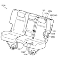
- the vehicle seat S100 is, as shown in FIG. 17, a seat body including a seat back 101, a seat cushion 102, and a headrest 103, and is mounted between the seat body and the vehicle body floor as shown in FIG.
- a switching device 150 As shown in FIGS.
- the vehicle seat S100 includes a wire member 160 attached to a lower end portion of the seatback 101 and serving as an anchor for connecting a child seat.
- a concave storage floor (not shown) formed at a lower position than the vehicle body floor is provided on the front side of the vehicle seat S100.
- the vehicle seat S100 is a seat in which at least two types of seat arrangements are possible: a use state in which an occupant can sit and a storage state in which a seat body is stored on a storage floor. More specifically, when the occupant pulls the operation lever 151 shown in FIG. 17 from the use state, the seat body of the vehicle S100 is folded forward and folded, and is switched to the storage state stored in the storage floor. In addition, from the stowed state, the occupant manually returns the seat body upward to return to the use state.
- the seat back 101 is a backrest portion for supporting the back of the occupant from behind, and the cushion pad 101a is placed on a back frame 110 shown in FIG. It is configured to be covered.
- the seat cushion 102 is a seating portion for supporting an occupant from below, and is provided with a cushion pad 102a placed on a cushion frame 120 serving as a skeleton shown in FIG. 2 and covered with a skin 2b from above the cushion pad 102a. It is configured.
- the headrest 103 is a head that supports the occupant's head from behind, and is configured by placing a cushion pad 103a on a headrest pillar (not shown) serving as a core material and covering the cushion pad 103a with a skin 103b.
- the back frame 110 is formed of a substantially rectangular frame-shaped body serving as a skeleton of the seat back 101.
- a frame-shaped main frame 111 made of a pipe material and a main frame 111 are disposed in the frame of the main frame.
- a connection frame 112 that connects an upper frame portion 111a that forms the upper portion of the main frame 111 and a lower frame portion 111b that forms the lower portion, and a plate-like shape that is attached to substantially the entire rear surface of the seat of the main frame 111 and the connection frame 112.
- a panel frame 113 is formed of a substantially rectangular frame-shaped body serving as a skeleton of the seat back 101.
- a retractor bracket 114 is attached to a substantially central portion of the panel frame 113 such that the connection frame 112 is sandwiched between the panel frame 113 and the seat frame in the front-rear direction of the seat.
- the retractor bracket 114 is a bracket for attaching a belt retractor (not shown) that winds up the seat belt, and is also a bracket for reinforcement.
- a plurality of substantially flat surfaces are formed at predetermined intervals in the seat width direction.
- a pair of headrest guides 103c for supporting a headrest pillar (not shown) are attached to the portions where these substantially flat surfaces are formed.
- a skin suspending wire 115 is attached to the lower end portion of the lower frame portion 111b of the main frame 111 by welding, and a pair of wire members 160 are provided at positions not overlapping the terminal portions of the pair of skin suspending wires 115. Are joined by welding.
- the wire member 160 on the left side of the seat is arranged outside the skin hanging wire 115 on the left side of the seat in the seat width direction, and the wire member 160 on the right side of the seat is at both ends of the skin hanging wire 115 on the right side of the seat. It is arranged in the position sandwiched between.
- a reinforcing bracket 116 connecting the lower end of the side frame 111c and the left end of the lower frame 111b is attached by welding.
- left and right mounting brackets 117 for connecting to the support base 140 are attached to the lower portions of the outer surfaces of the left and right side frame portions 111c and 111d in the main frame 111.
- a switching device 150 for switching the seat body from the use state to the storage state is attached to an upper portion of the outer side surface of the side frame portion 111c.
- connection frame 112 is made of a long pipe material, and has a substantially flat surface that is partially crushed by press working at its upper end and lower end. These substantially flat surfaces are attached to the outer surface of the main frame 111 by welding.
- the connection frame 112 is attached to the right side of the seat width direction opposite to the left side to which the reinforcing bracket 116 is attached. Therefore, the rigidity of the back frame 110 is well-balanced in the seat width direction.
- the panel frame 113 is a panel member having a substantially rectangular shape, and is attached to the upper, lower, left, and right frame portions of the main frame 111 by welding, respectively. Mounted by welding. More specifically, as shown in FIG. 19, a frame mounting projection 113a (not shown) projecting toward the main frame 111 is provided at a predetermined position of a portion of the panel frame 113 that overlaps with the main frame 111 in the front-rear direction of the seat. Are formed. The frame mounting projections 113a are welded in a state of being in contact with the respective frames.
- the lower end portion of the panel frame 113 extends below the lower frame portion 111b and is provided so as to cover the skin suspension wire 115 and the wire member 160 from behind. More specifically, the lower end portion of the panel frame 113 is bent and extends to the front of the seat, and covers the skin suspension wire 115 and the wire member 160 from behind and below. Therefore, even when a load is received from the outside in the front-rear direction of the seat or when a load is received from below, the assembling rigidity of these members can be ensured.
- a reinforcing recess 113b that is recessed toward the rear of the seat is formed in a lower portion of the panel frame 113 at a portion facing the reinforcing bracket 116 in the seat front-rear direction.
- the reinforcing recess 113b has the same width as the reinforcing bracket 116, and extends along the direction in which the reinforcing bracket 116 extends. More specifically, the outer end in the sheet width direction extends to a position facing the rear surface of the side frame portion 111c, and the inner end extends to a position facing the rear surface of the lower frame portion 111b.
- the rigidity of the panel frame 113 can be increased, and a gap is formed, so that the mounting workability of the reinforcing bracket 116 can be secured. Further, it is possible to suppress the generation of abnormal noise due to the contact between the components during the running of the vehicle.
- the skin suspending wire 115 is a wire for suspending the skin terminal portion of the seat cushion 102 or the seat back 101, and includes a wire main body 115a extending in the seat width direction, and a wire.
- a pair of wire extensions 115b that bend continuously from both left and right ends of the main body 115a and extend upward, and a pair of wires that bend continuously from the upper ends of the pair of wire extensions 115b and extend inward in the sheet width direction. It mainly comprises a pair of wire terminal portions 115c.
- a substantially central portion of the wire main body 115a is welded to the lower end of the panel frame 113, and a pair of wire ends 115c are welded to the bottom surface of the lower frame 111b.
- the one wire terminal portion 115c is disposed at a position corresponding to a portion of the lower frame portion 111b to which the reinforcing bracket 116 is attached in the seat width direction, in other words, at a position vertically overlapping. According to the above configuration, the assembling rigidity of the skin suspension wire 115 is improved.
- the reinforcing bracket 116 is a bracket for reinforcing the back frame 110, is formed in a substantially U-shaped cross section, and extends in the direction in which the connecting frame 112 extends (vertical direction). And the side frame portion 111c and the lower frame portion 111b are connected to each other. More specifically, the reinforcing bracket 116 bends continuously from the widthwise front end of the side wall portion 116a disposed inside the frame shape of the main frame 111 and the side wall portion 116a. The front wall portion 116b partially extending to the front surface and the rear end portion in the width direction of the side wall portion 116a continuously bend and partially extend to the rear surface of the main frame 111 while facing the front wall portion 116b.
- the outer ends of the front wall portion 116b and the rear wall portion 116c in the seat width direction are joined to the main frame 111 (side frame portion 111c) by welding, and the front wall portion 116b and the rear wall portion 116c. Is welded to the main frame 111 (the lower frame portion 111b).
- notches 116d for avoiding interference with the main frame 111 are formed at both ends of the side wall portion 116a of the reinforcing bracket 116 close to the main frame 111.
- the front wall portion 116b and the rear wall portion 116c extend so as to partially protrude from the side wall portions 116a, respectively, and are in contact with the outer surface of the main frame 111. And these contact parts are joined and the welding mark is respectively formed.
- both end portions of the reinforcing bracket 116 in the seat width direction are assembled so as to sandwich the main frame 111, and both end portions are joined by welding on both sides in the seat front-rear direction. Therefore, the rigidity is improved in the portion where the reinforcing bracket 116 is assembled and the peripheral portion.
- a step portion 116e bent rearward in the front-rear direction of the seat is formed in a peripheral portion (specifically, a proximity portion) of an end portion attached to the lower frame portion 111b.
- the upper portion has a shape recessed rearward with respect to the lower portion.
- the mounting bracket 117 is made of a sheet metal member extending in the up-down direction, is formed in a substantially bow shape when viewed from the side of the seat, and the upper portion of the mounting bracket 117 is a main frame. 111 is attached to the outer surface in the sheet width direction, and the lower end portion is attached to the inner surface of the support base 140. More specifically, as shown in FIG. 21, the mounting bracket 117 has a substantially U-shaped cross section, and has a side wall 117 a disposed on an outer side surface in the seat width direction of the main frame 111, and a width direction of the side wall 117 a.
- the front wall 117b extends continuously from the front end of the main frame 111 and extends continuously from the widthwise rear end of the side wall 117a, and faces the front wall 117b. And a rear wall portion 117c extending to the rear surface of the main frame 111.
- the side wall portion 117a extends vertically along the main frame 111, and has a lower end portion attached to be rotatable with respect to the support base 140. Further, the inner ends in the seat width direction of the front wall portion 117b and the rear wall portion 117c are joined to the main frame 111 (side frame portions 111c and 111d) by welding.
- the shape of the main frame 111 is A bent portion 117d is formed to be bent inward along the sheet width direction. That is, a gap (space) is formed between a portion of the mounting bracket 117 where the bent portion 117d is formed and a component disposed outside the mounting bracket 117 in the seat width direction. Therefore, the mounting rigidity of the mounting bracket 117 to the main frame 111 is increased, and the workability of assembling the mounting bracket 117 to the support base 140 is improved.
- a notch 117 e for avoiding interference with the reinforcing bracket 116 is formed in a portion of the mounting bracket 117 facing the outer end in the sheet width direction of the reinforcing bracket 116.
- the front wall portion 117b and the rear wall portion 117c partially extend inward in the seat width direction so as to cover the main frame 111 while avoiding portions facing the outer end of the reinforcing bracket 116, respectively.
- the extending portions are joined to form welding marks. Therefore, the assembling workability and welding workability of the reinforcing bracket 116 or the mounting bracket 117 are improved, and the rigidity is improved in a portion where these components are mounted and in a peripheral portion.
- the upper end of the mounting bracket 117 is sandwiched between the back frame 110 (main frame 111) and the cushion frame 120 in the seat width direction.
- a lower end of the left mounting bracket 117 is provided with a seat rotation shaft 118 supported by a support base 140 in the seat width direction, and a lower end of the right mounting bracket 117.
- a reclining device 119 for rotatably connecting the back frame 110 to the support base 140 is attached to the support base 140.
- the reclining device 119 is a known device, and is attached to the outer surface of the right attachment bracket 117 in the seat width direction as shown in FIG.
- the reclining device 119 is provided with a spiral spring (not shown) that rotates the back frame 110 forward about the seat rotation shaft 118 and urges the back frame 110 to the stored state.
- One end of the spiral spring is locked to the back frame 110 side, and the other end is locked to the support base 140 side.
- the reclining device 119 operates when the locked state of the seat back 101 is released in accordance with the operation of the operation lever 151, and the back frame 110 is rotated forward by the biasing force of the spiral spring to be folded toward the vehicle body floor. Can be.
- the cushion frame 120 is formed of a substantially rectangular frame-like body serving as a skeleton of the seat cushion 102. As shown in FIG. 18, left and right side frames 121 disposed on the left and right sides, and a front portion of each side frame 121. , A central connecting pipe 123 that connects a substantially central portion in the front-rear direction of each side frame, a pan frame 124 as a plate-shaped frame that connects the front connecting pipe 122 and the central connecting pipe 123, It is mainly composed of
- the side frame 121 is formed of a sheet metal member having a substantially U-shaped cross section extending in the front-rear direction of the seat. Mounted on the side. At the rear end of the left side frame 121, a cushion rotation device 126 that connects the cushion frame 120 to the back frame 110 so as to be rotatable around the cushion rotation shaft 127 is attached.
- the front connection pipe 122 is formed of a substantially U-shaped pipe member, and its inner surface in the seat width direction has support legs 130 centered on the leg rotation shaft 129 with respect to the cushion frame 120.
- a leg rotation device 128 for rotatably connecting the two is mounted.
- the support leg 130 is a substantially U-shaped pipe member that supports the seat cushion 102, and includes a leg body 131 disposed on the left and right sides and a lower end of each leg body 131. And a leg connecting portion 132 to be connected.
- the upper end of the leg body 131 is connected to the central portion in the seat longitudinal direction on the left and right inner side surfaces of the cushion frame 120.
- the center of the leg connecting portion 132 in the seat width direction is detachably held by a leg holding member (not shown) on the vehicle body floor.
- the upper end of the support leg 130 protrudes forward of the seat from the lower end of the support leg 130, and is inclined forward and upward from the lower end of the support leg 130 toward the upper end of the support leg 130.
- the support base 140 is a member that supports the seat back 101, and as shown in FIG. 18 and FIG. And connected to the vehicle floor.
- the support base 140 extends upward from the left and right outer ends of the connecting wall 141 and the connecting wall 141 connected to the upper surface of the vehicle body floor, and extends through the seat rotating shaft 118 to the lower end of the mounting bracket 117.
- an outer wall 142 connected to the outer wall 142.
- the switching device 150 is a known device for switching the vehicle seat S100 from the use state to the storage state, and is attached to an upper portion of the back frame 110 as shown in FIGS.
- the switching device 150 includes an engagement hook detachably provided to an engagement striker (not shown) that is a part of a vehicle body member, and an engagement striker that moves a tip end of the engagement hook in a vertical direction of the seat. And an operation lever 151 for engaging and locking the lock.
- the engaging hook is connected to the operating lever 151 via a cable (not shown).
- the operating lever 151 can be used to lock the engaging hook to the engaging striker. It is configured to be switchable.
- the locked state of the back frame 110 by the switching device 150 is released.
- the reclining device 119 operates in accordance with the release of the locked state of the seat back 101, and more specifically, the back frame 110 can be rotated forward and folded by the urging force of a spiral spring (not shown).
- the cushion rotation device 126 and the leg rotation device 128 respectively operate with the rotation operation of the back frame 110, and specifically, the support leg 130 is moved by the urging force of a spiral spring (not shown) to move the leg rotation shaft 129. It can be folded by rotating it toward the cushion frame 120 as a center.
- the seat body is stored on the storage floor, and the vehicle seat S100 is switched from the used state to the stored state.
- the occupant lifts the seat body by hand against the urging force of a spiral spring (not shown) to engage the switching device 150.
- the back frame 110 may be switched to the locked state by engaging the hook with the engagement striker.
- the wire member 160 is an anchor for connecting the child seat, and is attached as a pair to the lower end of the main frame 111 at a predetermined interval in the seat width direction as shown in FIGS. . More specifically, as shown in FIG. 21, the pair of wire members 160 has a substantially U-shape, and is continuous from a wire body 161 extending in the sheet width direction and an inner end of the wire body 161 in the sheet width direction. It mainly comprises an inner end 162 which is bent and extends rearward of the seat, and an outer end 163 which continuously bends from the outer end of the wire main body and extends rearward of the seat.
- the inner end 162 of the left wire member 160 extends rearward of the seat along the outer peripheral surface of the lower frame portion 111b, and is in contact with the outer peripheral surface of the lower frame portion 111b. And the contact part is joined and the welding mark is formed. Further, an outer end 163 extends rearward along the outer surface of the mounting bracket 117 in the seat width direction, and is in contact with the outer surface. The contact portions are joined to form welding marks. On the other hand, as for the right wire member 160 ', the inner end 162 and the outer end 163 extend rearward along the outer peripheral surface of the lower frame portion 111b and are in contact with the outer peripheral surface. And the contact part is joined and the welding mark is formed.
- the left wire member 160 will be described.
- the inner end portion 162 extends in a hook shape so as to cover the bottom surface and the rear surface of the outer peripheral surface of the lower frame portion 111b, and is welded in contact with the bottom surface and the rear surface. For this reason, the structure is well-balanced in consideration of the workability of assembling the wire members while increasing the assembling rigidity of the wire members 160 to the main frame 111.
- the wire body 161 and the outer end 163 extend so as to cover the front and outer surfaces of the mounting bracket 117, and are welded in contact with the front and outer surfaces. Therefore, since the wire member 160 is supported by the mounting bracket 117 from the rear to the front of the seat and from the inside to the outside in the seat width direction, the assembling rigidity of the wire member 160 is remarkably improved. For example, the assembling rigidity of the wire member is significantly increased as compared with the case where the outer end portion 163 is attached to the inner surface of the attachment bracket 117.
- the outer end 163 is disposed in a gap provided between the side frame 121 and a portion of the mounting bracket 117 where the bent portion 117 d is formed in the seat width direction.
- the wire member 160 is arranged at a position not protruding beyond the main frame 111 in the seat width direction, that is, inside the outer surface of the main frame 111. Therefore, in addition to improving the rigidity of the mounting bracket 117 itself and the rigidity of assembling the wire member 160, interference between the wire member 160 and other components can be suppressed. In particular, in the vehicle seat S100 in which the seat can be arranged between the use state and the storage state as in the present embodiment, interference with a component that rotates such as the cushion frame 120 can be avoided. Effect.
- the vehicle seat S100 is formed as a rear seat of the vehicle, but is not particularly limited, and may be a front seat of the vehicle, or three rows. In a vehicle having a seat, a middle seat may be used.
- the vehicle seat S100 is a seat that can be arranged in a seating state between a use state and a storage state, but is not particularly limited.
- the seat may be a seat that can be arranged in three different forms, that is, a tip-up state in which the sheet is flipped up.
- the storage floor is formed in front of the vehicle seat S100, the storage floor may be formed behind the vehicle seat S100 without any particular limitation.
- the support base 140 is directly fixed to the vehicle body floor.
- the support base 140 is not particularly limited.
- the seat body can be moved in the front-rear direction. It may be indirectly fixed on the vehicle body floor via a supporting rail device.
- the reinforcing bracket 116 and the mounting bracket 117 are attached to the main frame 111 by welding.
- the welding method is not particularly limited, and may be laser welding, arc welding, spot welding, or the like. Various welding methods may be adopted.
- the mounting bracket 117 has an upper portion attached to the back frame 110 and a lower portion attached to the support base 140, but is not particularly limited. Can be changed.
- the lower part of the mounting bracket 117 may be mounted on the cushion frame 120 or may be mounted on a separately provided rail device.
- the inner end 162 of the wire member 160 extends along the outer peripheral surface of the lower frame portion 111b, but is not particularly limited. It may extend through the lower frame portion 111b and be attached by welding. Similarly, the outer end 163 may extend through the mounting bracket 117 in the seat width direction and may be attached by welding.
- a storable vehicle seat used for an automobile has been described as a specific example.
- the present invention is not limited to this.
- a vehicle seat such as a train or a bus
- a vehicle such as an airplane or a ship may be used. It can also be used as a seat.
- the vehicle seat S100 mainly the description has been given of the vehicle seat S100 according to the present invention.
- the above-described second embodiment is merely an example for facilitating the understanding of the present invention, and does not limit the present invention.
- the present invention can be modified and improved without departing from the gist thereof, and it is needless to say that the present invention includes equivalents thereof.
- the shape, arrangement, and configuration of the back frame 110, the reinforcing bracket 116, the mounting bracket 117, and the wire member 160 described in the above embodiment are merely examples, and do not limit the present invention. Absent.
- ⁇ Vehicle seat according to third embodiment> Next, a vehicle seat according to a third embodiment will be described. In describing the vehicle seat according to the third embodiment, issues regarding a vehicle seat will be described.
- a vehicle seat in which a belt guide for guiding a seat belt is attached to an upper end of a back frame serving as a skeleton of a seat back.
- a vehicle rear seat has been proposed in which a belt retractor for winding a seat belt is attached to a center portion of a back frame, and a seat belt pulled out from the belt retractor is guided by a belt guide.
- a frame-shaped main frame made of a pipe material, a connection frame connecting the upper end and the lower end within the frame of the main frame, and the entire rear surface of the frame are attached.
- a back frame composed of a plate-shaped panel frame.
- a mounting bracket for mounting the belt retractor is fastened to the central portion on the panel frame and is also joined to the connection frame, thereby securing the rigidity of the belt retractor.
- a frame-shaped main frame made of a pipe material, an elastic wire connecting upper and lower ends in a frame of the main frame, and left and right ends in a seat width direction
- a back frame composed of an elastic wire connecting the two.
- An attachment bracket for attaching the belt retractor is attached to the elastic wire extending vertically in the frame of the main frame and the elastic wire extending in the seat width direction, thereby reducing the weight of the seat frame and supporting the occupant. Is secured.
- Patent Document 2 As described above, there has been a demand for a structure in which the weight of the seat frame is reduced and the support of the occupant is considered. In addition to the above, there has been a demand for a device capable of assembling the frame with a simple structure.
- the present invention has been made in view of the above problems, and an object of the present invention is to provide a vehicle seat having a belt retractor, in which the weight of the seat frame is reduced while the rigidity of the belt retractor is improved, and It is another object of the present invention to provide a vehicle seat that secures good supportability. Another object of the present invention is to provide a vehicle seat to which a frame can be assembled with a simple structure.
- the above-mentioned problem constitutes a skeleton of a backrest portion, a main frame formed of a frame-like body, and a main frame arranged in the main frame.
- a connection frame that connects an upper frame part that forms an upper part and a lower frame part that forms a lower part; and left and right side frames that are arranged in the frame of the main frame and that form side parts of the main frame in the seat width direction.
- the vehicle seat is provided with an elastic support member for connecting the side portions of the main frame in the seat width direction within the frame of the main frame and supporting the occupant
- the conventional vehicle seat has Compared with a configuration in which a plate-shaped panel frame is attached to the rear surface, it is possible to reduce the weight of the seat frame and secure good support for a seated person. Therefore, it is possible to realize a vehicle seat in which the weight of the seat frame is reduced and the good support of the occupant is ensured while improving the assembling rigidity of the belt retractor with a simple structure as compared with the related art.
- the mounting bracket has a frame mounting recess on the front surface of the panel bracket, which is bent toward the connection frame for mounting along the outer surface of the connection frame, and a frame mounting recess. And a frame attachment end provided at at least one end in the vertical direction and extending toward the connection frame for attachment to an outer surface of the connection frame. It is preferable that at least an upper end portion and a lower end portion of the outer peripheral portion of the mounting bracket are formed with an upper end flange and a lower end flange extending rearward toward the panel bracket, respectively. According to the above configuration, the mounting rigidity of the mounting bracket can be improved, and the rigidity can be expected to be improved by the U-shaped cross section, so that the belt retractor can be mounted more stably.
- the mounting bracket is disposed on a side closer to the elastic support member in a vertical direction between the upper frame portion and the elastic support member. As described above, the mounting bracket is mounted in the lower space closer to the elastic support member than the upper frame portion in the up-down direction, so that it is easy to secure a mounting space for the belt retractor. In addition, since the mounting bracket also functions as a reinforcing bracket, the mounting rigidity of the elastic support member is improved, and good support of the occupant can be secured.
- an outer peripheral flange extending toward the front of the seat and a notch portion cut out at at least one corner are formed on the outer peripheral portion of the panel bracket.
- the panel bracket is disposed on one end side in the seat width direction, and a frame mounting protrusion protruding toward the connection frame for mounting on the outer surface of the connection frame, and is disposed on the other end side in the seat width direction. And a bracket mounting projection projecting toward the mounting bracket for mounting the mounting bracket.
- the panel bracket is provided above a portion where the mounting bracket is mounted, and a reinforcing concave portion that is recessed on a side opposite to the mounting bracket side, and a region where the reinforcing concave portion is formed.
- a reinforcing protrusion protruding toward the mounting bracket, and the reinforcing protrusion is preferably formed at a position facing a seat belt extending from the belt retractor.
- a portion of the upper frame portion whose position overlaps with the panel bracket in the seat width direction is formed of a wire member, and a belt guide for guiding the seat belt is attached, and the reinforcing protrusion is The belt guide is preferably provided between both end portions to which the belt guide is attached in the sheet width direction.
- a support member connecting portion for connecting to the elastic support member may be provided in a portion between the mounting bracket and a lower end of the panel bracket in the vertical direction in the panel bracket.
- the main frame is formed of a pipe material, and a plurality of a pair of headrest guides for supporting a headrest pillar are attached to a portion where a substantially flat surface is formed on a front surface or a rear surface of the upper frame portion,
- the panel bracket may be attached between the plurality of headrest guides in the seat width direction in the upper frame portion.
- the mounting rigidity of the mounting bracket is improved, and the belt retractor can be mounted more stably.
- the assembling space for the belt retractor can be easily secured, and the assembling rigidity of the elastic support member is improved, so that good seating occupant supportability can be secured.
- the vehicle seat according to the third embodiment described below has a structure in which the stiffness of the panel bracket is improved while the workability of assembling the panel bracket and peripheral components is considered.
- the other portions are not in contact with other peripheral parts. Generation of accompanying noise can be suppressed.
- the rigidity of the panel bracket can be improved, and the seat belt can be stably pulled out from the belt retractor.
- the mounting rigidity of the panel bracket is improved while ensuring good support of the occupant.
- the riding comfort of the occupant can be improved, and the mounting rigidity of the panel bracket is further improved.
- This embodiment constitutes a skeleton of a backrest portion, a main frame made of a pipe-shaped frame, and a connection frame arranged in the main frame and connecting an upper frame portion and a lower frame portion of the main frame.
- An elastic support member arranged in the frame of the main frame, connecting the left and right side frame portions in the seat width direction of the main frame, and an elastic support member for supporting a occupant.
- Panel brackets respectively attached to the portion, the connection frame and the elastic support member, and attached to the front of the panel bracket to attach the belt retractor, and provided so as to sandwich the connection frame between the panel brackets in the seat front-back direction.
- the invention of a vehicle seat characterized by comprising a mounting bracket It is intended to. The side where the occupant sits with respect to the seat back of the vehicle seat is the front side.
- the vehicle seat S200 of the third embodiment is a rear seat corresponding to, for example, a rear seat of the vehicle.
- the vehicle seat S200 is attached to a seat body including a seatback 201, a seat cushion 202, and a headrest 203, and is mounted inside the seatback 201 to restrain an upper body of a seated person.
- a support leg 230 attached between the seat cushion 202 and the vehicle body floor and supporting the seat cushion 202, and a support base 240 rotatably supporting the seat back 201 as shown in FIG.
- a switching device 250 attached to an outer portion of the seat back 201 in the seat width direction to switch the seat body from the use state to the storage state.
- a concave storage floor (not shown) formed at a lower position than the vehicle body floor is provided on the front side of the vehicle seat S200.
- the vehicle seat S200 is a seat in which at least two types of seat arrangements are possible: a use state in which an occupant can sit and a storage state in which the seat body is stored on a storage floor. Specifically, when the occupant pulls the operation lever 252 shown in FIG. 24 from the use state, the seat body of the vehicle seat S200 falls forward and is folded, and is switched to the storage state stored in the storage floor. In addition, from the stowed state, the occupant manually returns the seat body upward to return to the use state.
- the seat back 201 is a backrest portion for supporting the back of the occupant from behind, and the cushion pad 201a is placed on the back frame 210 shown in FIG. It is configured to be covered.
- the seat cushion 202 is a seating portion for supporting an occupant from below, and is provided with a cushion pad 202a placed on a cushion frame 220 serving as a skeleton shown in FIG. 25 and covered with a skin 202b from above the cushion pad 202a. It is configured.
- the headrest 203 is a head that supports the occupant's head from behind, and is configured by placing a cushion pad 203a on a headrest pillar (not shown) serving as a core material and covering the cushion pad 203a with a skin 203b.
- the seatbelt device 204 includes a seatbelt 204a that restrains the upper body of the occupant, a belt retractor 204b that is attached to the back frame 210 and winds the seatbelt 204a so that it can be pulled out, and FIG.
- a belt guide 204c is mounted on the back frame 210 at a position higher than the belt retractor 204b and guides the seat belt 204a pulled out from the belt retractor 204b.
- a belt tongue plate (not shown) is attached to the end of the seat belt 204a, and the belt tongue plate is configured to be detachably connected to a belt buckle (not shown).
- the back frame 210 is formed of a substantially rectangular frame-like body serving as a skeleton of the seat back 201, and as shown in FIG. 25, a frame-shaped main frame 211 made of a pipe material, and a frame inside the main frame 211.
- a connecting frame 212 that is arranged and connects an upper frame portion 211a that forms an upper portion of the main frame 211 and a lower frame portion 211b that forms a lower portion, and left and right side frame portions 211c and 211d that form side portions of the main frame 211.
- an elastic support member 213 for supporting a seated person.
- a panel bracket 214 attached to the upper frame portion 211a, the connection frame 212, and the elastic support member 213, respectively, and a belt retractor 224b attached to the front of the panel bracket 214 are attached.
- Mounting bracket 215 is provided on the upper portion of the main frame 211.
- a plurality of substantially flat surfaces are formed at predetermined intervals in the seat width direction.
- a pair of headrest guides 203c for supporting a headrest pillar (not shown) are attached to the portions where these substantially flat surfaces are formed.
- a reinforcing bracket v216 connecting the lower end of the side frame 211c and the left end of the lower frame 211b is attached by welding.
- Left and right vehicle body connection brackets 217 for connecting to the support base 240 are attached to lower portions of outer side surfaces of the left and right side frame portions 211c and 211d of the main frame 211.
- a switching device 250 for switching the seat body from the use state to the storage state is attached to an upper portion of the outer side surface of the side frame portion 211c.
- connection frame 212 is made of a long pipe material, and has a substantially flat surface partially crushed by press working at its upper end and lower end. Is formed. These substantially flat surfaces are attached in contact with the outer peripheral surface of the main frame 211 while slightly curved along the outer peripheral surface. More specifically, both ends in the sheet width direction of these substantially flat surfaces are welded to the front surface of the main frame 211. As shown in FIG. 25, the connection frame 212 is attached to the right side of the seat width direction opposite to the left side to which the reinforcing bracket 216 is attached. Therefore, the rigidity of the back frame 210 is well-balanced in the sheet width direction.
- the elastic support member 213 is an elastic spring that supports the backrest of the occupant, is bridged between the left and right side frame portions 211c and 211d, and extends vertically. A plurality are arranged at predetermined intervals. More specifically, the elastic support member 213 has a substantially U-shape elongated in the sheet width direction, and as shown in FIG. 26, a spring body portion 213 a extending substantially linearly in the sheet width direction, The left and right spring ends 213b and 213c continuously bend and extend downward from both ends in the sheet width direction of the portion 213a.
- the left and right spring ends 213b and 213c extend downward along the inner surfaces of the left and right side frame portions 211c and 211d, respectively, and are laser-welded in contact with the inner surfaces of the side frame portions 211c and 211d. I have.
- the spring main body 213a extends in a direction intersecting (orthogonal to) the connection frame 212 and partially abuts on the rear surface of the connection frame 212. Are joined by welding. Further, the spring body 213a also extends in a direction intersecting with the panel bracket 214, and partially contacts the front surface of the lower end portion of the panel bracket 214, and the contact portion is laser-joined. As described above, since the elastic support member 213 is assembled to the back frame 210 by the left and right side frame portions 211c and 211d, the connection frame 212, and the panel bracket 214, the mounting rigidity of the elastic support member 213 increases. Good support for the seated person can be secured.
- a substantially V-shaped portion of the elastic support member 213 protruding upward from the spring body 213a is provided on the left side of the elastic support member 213 opposite to the right side attached to the connection frame 212 in the seat width direction.
- a bent portion 213d having a shape is formed.
- a bent portion 213d is formed for each of the elastic support members 213 arranged at intervals in the vertical direction, and each bent portion 213d overlaps in the sheet width direction, that is, at a vertical position. They are arranged at opposing positions. Therefore, the rigidity of the elastic support member 213 increases in a well-balanced manner in the seat width direction, so that good supportability for the seated person can be secured. Further, even when a load is received from one side in the seat front-rear direction due to the collision of the vehicle, the load energy can be efficiently absorbed.
- the panel bracket 214 is a substantially rectangular plate-like member as shown in FIGS. 25 to 27A and 27B, and is a bracket for attaching the seat belt device 204 shown in FIG. 29 to the back frame 210. Also, it is a bracket for reinforcing the back frame 210.
- the upper portion of the panel bracket 214 is attached to a substantially central portion of the upper frame portion 211a sandwiched between the plurality of headrest guides 203c in the seat width direction. More specifically, as shown in FIGS. 27A and 27B, the upper end portion of the panel bracket extends along the outer peripheral surface of the upper frame portion 211a so as to cover from the rear, and abuts against the rear surface of the upper frame portion 211a.
- the left and right end portions of the contacted portions are joined by laser welding.
- the panel bracket 214 has a substantially rectangular shape that is recessed on the opposite side (seat rear side) from the mounting bracket 215 side, above the portion where the mounting bracket 215 is mounted.
- a reinforcing recess 214a is formed.
- a substantially U-shaped reinforcing convex portion 214b protruding toward the mounting bracket 215 (front side of the seat) is formed. Therefore, in the region where the reinforcing concave portion 214a is formed, a substantially U-shaped concave portion, a reinforcing convex portion 214b, and a substantially rectangular convex portion are sequentially formed from the outside.
- a belt guide 204c made of a substantially U-shaped wire member is provided at both ends of the reinforcing recess 214a outside the portion where the reinforcing protrusion 214b is formed in the sheet width direction. Is attached. More specifically, both end portions of the belt guide 204c in the sheet width direction are sandwiched between the upper frame portion 211a and the reinforcing concave portion 214a in the seat front-rear direction, and are joined to the upper frame portion 211a by arc welding. The reinforcing recess 214a is joined by laser welding from the rear of the seat. Therefore, the assembly rigidity of the belt guide 204c and the panel bracket 214 is improved. Further, since the belt guide 204c is positioned in the sheet width direction with respect to the panel bracket 214, the assembling workability is improved.
- the reinforcing protrusion 214b is formed between both ends of the belt guide 204c in the sheet width direction, and extends in the vertical direction. Further, since the protrusion height of the reinforcing protrusion 214b is formed smaller than the recess depth of the reinforcing recess 214a, the protrusion of the reinforcing protrusion 214b does not protrude forward from the panel bracket 214 main body. I have. In other words, the reinforcing protrusion 214b is arranged at a position facing the seat belt 20a extending from the belt retractor 204b, so that the seat belt 204a can be stably supported from the rear of the seat without projecting forward. Can be.
- one end of the panel bracket 214 in the sheet width direction is attached to a substantially central portion of the connection frame 212 sandwiched between the upper frame portion 211a and the elastic support member 213 in the up-down direction.
- the panel bracket 214 is formed with a frame mounting projection 214c that projects forward toward the connection frame 212 to be mounted on the rear surface of the connection frame 212.
- the plurality of frame mounting protrusions 214c are formed at predetermined intervals in the up-down direction, are in contact with the rear surface of the connection frame 212, and the contacted portions are joined by laser welding.
- a support member connecting portion 214d for connecting to the elastic support member 213 is formed at a lower end portion of the panel bracket 214.
- a plurality of support member connecting portions 214d are formed at predetermined intervals in the sheet width direction.
- the lower part of the panel bracket 214 is attached to a part closer to the center than the part to which the upper frame part 211a, the connection frame 212, and the elastic support member 213 are attached.
- a bracket 215 is attached. More specifically, the panel bracket 214 is formed with a bracket mounting protrusion 214 e that projects forward toward the mounting bracket 215 to mount the mounting bracket 215.
- the bracket mounting protrusion 214e is in contact with the rear surface of the mounting bracket 215, and the contacted portion is joined by laser welding.
- the bracket mounting protrusion 214e is disposed at substantially the same height as the frame mounting protrusion 214c in the vertical direction, and is disposed between the plurality of support member connecting portions 214d in the seat width direction.
- an outer peripheral flange 214f extending toward the front of the seat is formed on the outer peripheral portion of the panel bracket 214.
- a cutout 214g is formed at all four corners of the outer peripheral portion. Therefore, interference with other components can be avoided while increasing the rigidity of the panel bracket 214.
- the mounting bracket 215 is a substantially rectangular plate-like member that is long in the sheet width direction, and is a bracket for mounting the belt retractor 204b to the back frame 210. It is also a bracket for reinforcing the back frame 210.
- the left portion of the mounting bracket 215 in the seat width direction has a substantially flat shape, and is attached to the front surface of the panel bracket 214 so as to face the front-rear direction. More specifically, the mounting bracket 215 is mounted on the panel bracket 214 (bracket mounting protrusion 214e) at a lower portion closer to the elastic support member 213 side than the upper frame portion 211a in the vertical direction.
- the right side portion of the mounting bracket 215 has a curved shape that is curved along the outer peripheral surface of the connection frame 212, and abuts to cover the front surface of the connection frame 212.
- the parts are joined by arc welding. More specifically, on the right side of the mounting bracket v215, a frame mounting recess 215a that is bent toward the connection frame 212 and is recessed to mount along the outer peripheral surface of the connection frame 212, and a frame mounting recess 215a.
- Frame mounting ends 215b and 215c are provided at an upper position and a lower position and protrude toward the connection frame 212, respectively.
- the right end of the frame attachment concave portion 215a, the upper end of the frame attachment end 215b, and the lower end of the frame attachment end 215c are welded to the connection frame 212, respectively.
- an outer peripheral flange 215d extending toward the panel bracket 214 is formed at an upper end portion, a left end portion, and a lower end portion of the outer peripheral portion of the mounting bracket 215.
- the outer peripheral flange 215d is in contact with the front surface of the panel bracket 214.
- a belt is provided at a substantially central portion surrounded by outer peripheral flanges 215d at upper and lower ends, a frame mounting concave portion 215a, and a portion mounted on the bracket mounting convex portion 214e.
- a retractor assembling portion 215e for assembling the retractor 204b is provided.
- the belt retractor 204b is attached to the center portion of the mounting bracket 215 where the rigidity is particularly increased, the attachment rigidity of the belt retractor 204b to the back frame 210 can be improved.
- the belt retractor 204b is assembled to the retractor assembly 215e as a box-shaped unit.
- the seat belt 204a is pulled out from a belt draw-out hole at the upper end portion of the belt retractor 204b and extends above the seat. Is guided along the front of the seat.
- the extended portion extending forward of the seat abuts on the upper surface of the belt guide 204c and is guided downward along the outer peripheral surface of the belt guide 204c.
- the belt guide 204c extends above the seat while being appropriately supported by the reinforcing protrusions 214b shown in FIGS. 27A and 29. Therefore, the operability of the seat belt 204a can be improved. Further, the belt guide 204c extending above the seat is guided forward of the seat through a gap formed between the upper frame portion 211a and the panel bracket 214. Therefore, the seat belt 204a can be stably arranged in the seat front-back direction.
- the reinforcing bracket 216 is a bracket for reinforcing the back frame 210, and has a substantially U-shaped cross section, and extends in the extending direction (up-down direction) of the connecting frame 212. It extends in the inclined direction and connects the side frame portion 211c and the lower frame portion 211b. More specifically, the reinforcing bracket 216 is bent from the side wall portion disposed inside the frame of the main frame 211 and the widthwise front end of the side wall portion, and extends to the front surface of the main frame 211. It comprises a front wall portion and a rear wall portion bent from the rear end in the width direction of the side wall portion and extending to the rear surface of the main frame 211. The outer ends of the front wall portion and the rear wall portion in the seat width direction are joined to the side frame portion 211c, and the inner ends of the front wall portion and the rear wall portion are connected to the lower frame portion 211b. Are joined.
- the vehicle body connection bracket 217 is made of a sheet metal member extending vertically, and an upper portion of the vehicle body connection bracket 217 is attached to an outer surface of the main frame 211 (side frame portion 211c) in the seat width direction. The lower end portion is attached to be rotatable with respect to the inner side surface of the support base 240. More specifically, the upper portion of the vehicle body connection bracket 217 extends vertically along the outer peripheral surface of the main frame 211 and is joined to the outer peripheral surface by welding.
- the upper end portion of the vehicle body connection bracket 217 is sandwiched between the back frame 210 (main frame 211) and the cushion frame 220 in the seat width direction.
- a seat rotation shaft 218 supported by the support base 240 in the seat width direction is provided at the lower end of the left vehicle body connection bracket 217.
- a reclining device 219 for rotatably connecting the back frame 210 is attached.
- the reclining device 219 is a known device, and is attached to the outer surface of the right vehicle body connection bracket 217 in the seat width direction as shown in FIG.
- the reclining device 219 includes a spiral spring (not shown) that rotates the back frame 210 forward about the seat rotation shaft 218 to urge the back frame 210 to the stored state.
- One end of the spiral spring is locked on the back frame 210 side, and the other end is locked on the support base 240 side.
- the reclining device 219 operates when the locked state of the seat back 201 is released with the operation of the operation lever 252, and the back frame 210 is rotated forward by the urging force of the spiral spring to be folded toward the vehicle body floor. Can be.
- the cushion frame 220 is formed of a substantially rectangular frame-like body serving as a skeleton of the seat cushion 202, and as shown in FIG. 25, left and right side frames 221 arranged on the left and right sides, and a front portion of each side frame 221.
- a central connecting pipe 223 that connects a substantially central portion in the front-rear direction of each side frame, a pan frame 224 as a plate-shaped frame that connects the front connecting pipe 222 and the central connecting pipe 223, It is mainly composed of
- the side frame 221 is formed of a sheet metal member having a substantially U-shaped cross-section extending in the front-rear direction of the seat. Mounted on the outside surface.
- a cushion rotation device 226 that connects the cushion frame 220 to the back frame 210 so as to be rotatable about the cushion rotation shaft 227 is attached to the rear end of the left side frame 221.
- the front connecting pipe 222 is formed of a substantially U-shaped pipe member, and its inner surface in the seat width direction has support legs 230 around the pivot shaft 229 with respect to the cushion frame 220.
- a leg rotation device 228 for rotatably connecting the two is mounted.
- the support leg 230 is a substantially U-shaped pipe member that supports the seat cushion 202. And a leg connecting portion 232 to be connected.
- the upper end of the leg body 231 is connected to the left and right inner side surfaces of the cushion frame 220 and to a substantially central portion in the front-rear direction.
- the center of the leg connecting portion 232 in the seat width direction is detachably held by a leg holding member (not shown) on the vehicle body floor.
- the upper end of the support leg v30 extends forward of the seat from the lower end of the support leg 230, and is inclined upward and forward from the lower end of the support leg 230 toward the upper end of the support leg 230.
- the support base 240 is a member that supports the seat back 201, and is made of a substantially L-shaped sheet metal member that is long in the front-rear direction as shown in FIG. It is connected to the floor.
- the support base 240 extends upwardly from the left and right inner ends of the connecting wall 241 connected to the upper surface of the vehicle body floor, and extends the seat rotation shaft 218 to the lower end of the vehicle body connecting bracket 217. And an outer wall portion connected through the outer wall portion.
- the switching device 250 is a known device for switching the vehicle seat S200 from the use state to the storage state, and is attached to an upper portion of the back frame 210 as shown in FIGS.
- the switching device 250 is provided with an engagement hook 251 detachably provided to an engagement striker (not shown) that is a part of a vehicle body member, and engages by moving a distal end portion of the engagement hook 251 in the seat up-down direction.
- An operation lever 252 for engaging and locking the striker.
- the engagement hook 251 is connected to the operation lever 252 via a cable (not shown). It is configured to be switchable.
- the locked state of the back frame 210 by the switching device 250 is released.
- the reclining device 219 shown in FIG. 25 operates with the release of the locked state of the seat back 201.
- the back frame 210 can be rotated forward and folded by the urging force of a spiral spring (not shown).
- the cushion rotation device 226 and the leg rotation device 228 shown in FIG. 25 operate with the rotation of the back frame 210.
- the support leg 230 is rotated by the urging force of a spiral spring (not shown). It can be folded by rotating it around the dynamic shaft 229 toward the cushion frame 220 side.
- the seat body is stored on the storage floor, and the vehicle seat S200 is switched from the used state to the stored state.
- the occupant lifts the seat body by hand against the urging force of a spiral spring (not shown) to engage the switching device 250.
- the back frame 210 may be switched to the locked state by engaging the hook 251 with the engagement striker.
- the vehicle seat S200 is formed as a rear seat of the vehicle.
- the vehicle seat S200 is not particularly limited, and may be a front seat of the vehicle, or a middle seat in a vehicle having three rows of seats. It may be.
- the vehicle seat S200 is a seat that can be arranged in a seat between a use state and a storage state, but is not particularly limited.
- the seat may be a seat that can be arranged in three types, that is, a tip-up state in which the sheet is flipped up.
- the storage floor is formed in front of the vehicle seat S200, but the storage floor may be formed behind the vehicle seat S200 without any particular limitation.
- the support base 240 is directly fixed to the vehicle body floor, but is not particularly limited.
- the vehicle body connection bracket 217 has an upper portion attached to the back frame 210 and a lower portion attached to the support base 240, but is not particularly limited. Can be changed without.
- the lower part of the vehicle body connection bracket 217 may be attached to the cushion frame 220, or may be attached to a separately provided rail device.
- a storable vehicle seat used for an automobile has been described as a specific example.
- the present invention is not limited to this. It can also be used as a seat.
- the third embodiment is merely an example for facilitating the understanding of the present invention, and does not limit the present invention.
- the present invention can be modified and improved without departing from the gist thereof, and it is needless to say that the present invention includes equivalents thereof.
- the shapes, arrangements, and configurations of the back frame 210, the panel bracket 214, and the mounting bracket 215 described in the above embodiment are merely examples, and do not limit the present invention.
Landscapes
- Engineering & Computer Science (AREA)
- Aviation & Aerospace Engineering (AREA)
- Transportation (AREA)
- Mechanical Engineering (AREA)
- Seats For Vehicles (AREA)
Abstract
シートクッションに対して傾動可能なシートバックを備えた乗物用シートにおいて、シートバックフレームの傾動をロックするロックユニットを取り付けたサイドフレーム周辺の強度を向上させるとともに、ロックユニットを安定して支持することが可能な乗物用シートの提供。シートクッション(S1)に対して傾動可能なシートバック(S2)を備えた車両用シート(S)であって、シートバック(S2)は、シートバックフレーム(2)と、車体に設けられた被係合部と係合してシートバックフレーム(2)の傾動をロックするロックユニット(30)と、を備え、シートバックフレーム(2)は、乗物用シートの上下方向に延在するサイドフレーム(3a)と、サイドフレーム(3a)の乗物用シートの幅方向における外側に取り付けられた取付ブラケット(10)と、を有し、ロックユニット(30)は、取付ブラケット(10)の乗物用シートの幅方向における外側面(11)に取り付けられており、サイドフレーム(3a)と取付ブラケット(10)が補強ブラケット(20)によって接続されている。
Description
本発明は、シートクッションに対して傾動可能なシートバックを備えた乗物用シートに係り、特に車体に設けられた被係合部と係合してシートバックの傾動をロックするロックユニットを備えた乗物用シートに関する。
シートバックを、シートクッションに対して近付く方向に傾動可能に構成した車両用シートにおいて、シートバックフレームにロックユニットを取り付けて、シートバックの傾動をロックする技術が知られている。
例えば、特許文献1には、パイプを枠状に折り曲げて形成されたフレーム部材の側部の角部にブラケットを設け、車体に支持されたストライカに係脱自在なロックユニットを取り付けたシートバックフレームが記載されている。乗員が着座する際には、ロックユニットをストライカと係合させ、ブラケット及びシートバックフレームは車体に対して固定される。
車両の前方及び後方からの衝突に対して、乗員を保護するためにシートフレームの強度を向上させることが求められているが、ブラケットを介してシートフレームに取り付けられたロックユニットの周囲においても、強度を向上させることで、安定してロックユニットを支持することが可能な構造が求められていた。
本発明は、上記の課題に鑑みてなされたものであり、その目的は、シートバックフレームにおいて、ロックユニットを取り付けたサイドフレーム周辺の強度を向上させるとともに、ロックユニットを安定して支持することが可能な乗物用シートを提供することにある。
前記課題は、本発明の乗物用シートによれば、シートクッションに対して傾動可能なシートバックを備えた乗物用シートであって、前記シートバックは、シートバックフレームと、車体に設けられた被係合部と係合して前記シートバックフレームの傾動をロックするロックユニットと、を備え、前記シートバックフレームは、前記乗物用シートの上下方向に延在するサイドフレームと、該サイドフレームの前記乗物用シートの幅方向における外側に取り付けられた取付ブラケットと、を有し、前記ロックユニットは、前記取付ブラケットの前記乗物用シートの幅方向における外側面に取り付けられており、前記サイドフレームと前記取付ブラケットが補強ブラケットによって接続されていること、により解決される。
上記のように構成された本発明の乗物用シートでは、ロックユニットを取り付けたサイドフレーム周辺の強度を補強ブラケットにより向上させることで、ロックユニットを安定して支持することが可能となる。
上記の乗物用シートにおいて、前記取付ブラケットは、前記乗物用シートの前後方向に前面及び後面を備え、前記前面及び前記後面は、前記外側面によって連結されており、前記補強ブラケットは、前記サイドフレームと前記取付ブラケットの前記前面を接続しているとよい。
上記の構成では、取付ブラケットの強度を適切に向上させることで、ロックユニットを一層安定して支持することが可能となる。
上記の構成では、取付ブラケットの強度を適切に向上させることで、ロックユニットを一層安定して支持することが可能となる。
上記の乗物用シートにおいて、前記取付ブラケットの前記後面は、前記乗物用シートの前後方向の前方に突出する凸部を有し、該凸部において、前記取付ブラケットが前記サイドフレームに取り付けられているとよい。
上記の構成では、取付ブラケットのサイドフレームに対する取付が安定なものとなるため、ロックユニットを一層安定して支持することが可能となる。
上記の構成では、取付ブラケットのサイドフレームに対する取付が安定なものとなるため、ロックユニットを一層安定して支持することが可能となる。
上記の乗物用シートにおいて、前記取付ブラケットは、前記後面及び前記外側面に跨る開口を備えているとよい。
上記の構成では、ロックユニットを取り付ける外側面を確保しつつ、取付ブラケットの剛性を低下させることなく、軽量化することが可能となる。
上記の構成では、ロックユニットを取り付ける外側面を確保しつつ、取付ブラケットの剛性を低下させることなく、軽量化することが可能となる。
上記の乗物用シートにおいて、前記取付ブラケットは、前記乗物用シートの上下方向に上面及び下面を備え、前記上面は、前記サイドフレームと係合する第1凹部を有し、前記下面は、前記サイドフレームと係合する第2凹部を有し、前記第1凹部及び第2凹部において、前記取付ブラケットが前記サイドフレームに取り付けられているとよい。
上記の構成では、取付ブラケットが、シート上下方向において上面の第1凹部と下面の第2凹部にてサイドフレームに取り付けられているため、取付ブラケットのサイドフレームに対する取付がより一層安定なものとなる。
上記の構成では、取付ブラケットが、シート上下方向において上面の第1凹部と下面の第2凹部にてサイドフレームに取り付けられているため、取付ブラケットのサイドフレームに対する取付がより一層安定なものとなる。
上記の乗物用シートにおいて、前記取付ブラケットは、前記上面及び前記下面にそれぞれスリットを備えているとよい。
上記の構成では、取付ブラケットの上面及び下面がそれぞれスリットを備える構成であるため、板材を折り曲げるなどしてスリットを備える上面及び下面を形成することが可能となるため、取付ブラケットを成形する際の作業が容易なものとなる。
上記の構成では、取付ブラケットの上面及び下面がそれぞれスリットを備える構成であるため、板材を折り曲げるなどしてスリットを備える上面及び下面を形成することが可能となるため、取付ブラケットを成形する際の作業が容易なものとなる。
上記の乗物用シートにおいて、前記補強ブラケットは、前記乗物用シートの前後方向に前端部及び後端部を備え、前記前端部及び前記後端部の間に延在する補強ビードが形成されているとよい。
上記の構成では、補強ビードを設けることで補強ブラケットの剛性を向上させることが可能となる。
上記の構成では、補強ビードを設けることで補強ブラケットの剛性を向上させることが可能となる。
上記の乗物用シートにおいて、前記補強ビードは、前記補強ブラケットの上端部に上側補強ビードを有し、前記補強ブラケットの下端部に下側補強ビードを有し、前記乗物用シートの前後方向において、前方から後方に向かうにつれて前記上側補強ビードと前記下側補強ビードとの間隔が広がっているとよい。
上記の構成では、補強ブラケットが前方から後方に向かうにつれて間隔が広がる上側補強ビード及び下側補強ビードを有しているため、乗物用シートの前後方向から加わる衝撃に対する強度を向上させることが可能となる。
上記の構成では、補強ブラケットが前方から後方に向かうにつれて間隔が広がる上側補強ビード及び下側補強ビードを有しているため、乗物用シートの前後方向から加わる衝撃に対する強度を向上させることが可能となる。
上記の乗物用シートにおいて、前記シートバックフレームの傾動のロックを解除するロック解除部材と、前記ロック解除部材を支持する支持ブラケットと、前記支持ブラケットに取り付けられたワイヤ部材を備え、前記ワイヤ部材は、一端部が前記取付ブラケットの前記外側面に取り付けられており、他端部が、前記シートバックフレームに取り付けられているとよい。
上記の構成では、ロック解除部材を簡素な構造によって固定することが可能となる。
上記の構成では、ロック解除部材を簡素な構造によって固定することが可能となる。
上記の乗物用シートにおいて、前記支持ブラケットは、前記乗物用シートの前後方向において、前方部及び後方部を備え、前記前方部は、前記取付ブラケットに取り付けられ、前記後方部は、前記ワイヤ部材に取り付けられているとよい。
上記の構成では、ロック解除部材を安定して固定することが可能となる。
上記の構成では、ロック解除部材を安定して固定することが可能となる。
本発明の乗物用シートによれば、ロックユニットを取り付けたサイドフレーム周辺の強度を補強ブラケットにより向上させることで、ロックユニットを安定して支持することが可能となる。
また、本発明の乗物用シートによれば、取付ブラケットの強度を適切に向上させることで、ロックユニットを一層安定して支持することが可能となる。
また、本発明の乗物用シートによれば、取付ブラケットのサイドフレームに対する取付が安定なものとなるため、ロックユニットを一層安定して支持することが可能となる。
また、本発明の乗物用シートによれば、ロックユニットを取り付ける外側面を確保しつつ、取付ブラケットの剛性を低下させることなく、軽量化することが可能となる。
また、本発明の乗物用シートによれば、取付ブラケットが、シート上下方向において上面の第1凹部と下面の第2凹部にてサイドフレームに取り付けられているため、取付ブラケットのサイドフレームに対する取付がより一層安定なものとなる。
また、本発明の乗物用シートによれば、取付ブラケットの上面及び下面がそれぞれスリットを備える構成であるため、板材を折り曲げるなどしてスリットを備える上面及び下面を形成することが可能となるため、取付ブラケットを成形する際の作業が容易なものとなる。
また、本発明の乗物用シートによれば、補強ビードを設けることで補強ブラケットの剛性を向上させることが可能となる。
また、本発明の乗物用シートによれば、補強ブラケットが前方から後方に向かうにつれて間隔が広がる上側補強ビード及び下側補強ビードを有しているため、乗物用シートの前後方向から加わる衝撃に対する強度を向上させることが可能となる。
また、本発明の乗物用シートによれば、ロック解除部材を簡素な構造によって固定することが可能となる。
また、本発明の乗物用シートによれば、ロック解除部材を安定して固定することが可能となる。
<第1実施形態に係る車両用シート>
以下、図1乃至図16を参照しながら、本発明の第1実施形態(以下、本実施形態)に係る乗物用シートについて、車両に搭載される車両用シートを例に挙げて説明する。
以下、図1乃至図16を参照しながら、本発明の第1実施形態(以下、本実施形態)に係る乗物用シートについて、車両に搭載される車両用シートを例に挙げて説明する。
なお、以下に説明する実施形態は、本発明の理解を容易にするための一例に過ぎず、本発明を限定するものではない。すなわち、以下に説明する部材の形状、寸法、配置等については、本発明の趣旨を逸脱することなく、変更、改良され得るとともに、本発明にはその等価物が含まれることは勿論である。
本明細書における方向を示す用語に関し、図1のように各方向を定義する。具体的には、以下の説明中、「前後方向」とは、車両用シートの着座者から見たときの前後方向を意味し、車両の走行方向と一致する方向である。「シート幅方向」とは、車両用シートの横幅方向を意味し、車両用シートの着座者から見たときの左右方向と一致する。また、「上下方向」とは、車両用シートの高さ方向を意味し、車両用シートを正面から見たときの上下方向と一致している。
[1.車両用シートSの主要構成]
本実施形態の車両用シートSは、例えば車両の後部右側の座席に相当するリアシートである。本実施形態に係る車両用シートSは、図1に図示した外観を有している。なお、図1中、車両用シートSの一部については、図示の都合上、トリムカバーを外した構成にて図示している。
本実施形態の車両用シートSは、例えば車両の後部右側の座席に相当するリアシートである。本実施形態に係る車両用シートSは、図1に図示した外観を有している。なお、図1中、車両用シートSの一部については、図示の都合上、トリムカバーを外した構成にて図示している。
車両用シートSは、着座者の臀部を支える着座部分となるシートクッションS1、着座者の背部を支える背もたれ部分となるシートバックS2、及び、シートバックS2の上部に配され、着座者の頭部を支えるヘッドレストS3を主な構成要素として有する。なお、シートバックS2は不図示の支持ベースによって回動可能に支持されている。
車両用シートSは、乗員が着座可能な使用状態から、シートクッションS1、シートバックS2及びヘッドレストS3(以下、シート本体という)を収納フロアに収納した収納状態へ移行可能である。具体的には、車両用シートSは、使用状態から、操作レバー(後述するロック解除部材41)を引っ張ることで、シートバックS2及びヘッドレストS3がシートクッションS1に対して近付く方向に傾動して折り畳まれ、収納フロアに収納された収納状態に切り替わる。また、収納状態から、乗員が手動でシート本体を上方に起こすことで使用状態に復帰する。
シートクッションS1は、図2に示す骨格となるシートクッションフレーム1にクッションパッドS11を載置し、更にクッションパッドS11をトリムカバーS12で覆うことで構成されている。シートバックS2は、図2に示す骨格となるシートバックフレーム2にクッションパッドS21を載置して、トリムカバーS22で覆うことで構成されている。ヘッドレストS3は、不図示の芯材にクッションパッドS31を配して、トリムカバーS32で被覆して形成されている。クッションパッドS11,S21,S31は、ウレタンフォームなどの弾性を有するクッション材からなり、トリムカバーS12,S22,S32は、合成皮革や布地などからなり、複数の表皮材が縫製されて形成されている。
[2.シートフレームの概要]
まず、図2を参照しながら、シートフレームFの構成の概要について説明する。図2では、図1に示す車両用シートSの右側のシートのシートフレームFを図示している。図2に示されるように、シートフレームFは、主にシートクッションフレーム1及びシートバックフレーム2により構成される。シートクッションフレーム1は、車両用シートSにおける着座部分の骨格をなし、シートバックフレーム2は、車両用シートSにおける背もたれ部分の骨格をなす。
まず、図2を参照しながら、シートフレームFの構成の概要について説明する。図2では、図1に示す車両用シートSの右側のシートのシートフレームFを図示している。図2に示されるように、シートフレームFは、主にシートクッションフレーム1及びシートバックフレーム2により構成される。シートクッションフレーム1は、車両用シートSにおける着座部分の骨格をなし、シートバックフレーム2は、車両用シートSにおける背もたれ部分の骨格をなす。
シートクッションフレーム1は、図2に示されるように、上方から見たときに方形枠状の外形形状をなしている。そして、シートクッションフレーム1は、シート幅方向における端部を構成するサイドフレームと、シートクッションフレーム1の前端部を構成するパンフレームと、を主たる構成要素とする。シートクッションフレーム1は、支持脚1aを備えており、乗員が着座可能な使用状態において、図1に示すように、支持脚1aが不図示の支持ベースに係合して固定されている。
シートバックフレーム2は、パイプフレーム3と、パイプフレーム3のシート後面に設けられたバックパネル4を備えている。パイプフレーム3は、金属製のパイプ部材を折り曲げて形成した略矩形状の枠状体であり、図2に示すように、左右に離間して配置され長手方向(シート上下方向)に延在する一対のサイドフレーム3aと、この一対のサイドフレーム3aの上端部を連結する上部フレーム3bと、下端部を連結する下部フレーム3cとによりに構成されている。
上部フレーム3bの前面には、シート幅方向に略平坦面が形成されている。この略平坦面が形成された部分には、不図示のヘッドレストピラーを支持するための一対のピラー支持部がそれぞれ取り付けられている。ピラー支持部には、不図示のヘッドレストピラーが挿入され、ヘッドレストS3が取り付けられる。
バックパネル4は、略矩形状からなる金属製のパネル部材である。バックパネル4は、シート幅方向において左右の端部がパイプフレーム3の左右のサイドフレーム3aに対してそれぞれ溶接で取り付けられている。また、バックパネル4は、シート上下方向において上方部分及び下方部分がそれぞれ上部フレーム3b及び下部フレーム3cに対して溶接で取り付けられている。
[3.ロックユニットの取付態様]
車両用シートSは、シートバックフレーム2(シートバックS2)の傾動をロックするロックユニット30を備えている。以下、図3及び図4を参照して、シートフレームFに対するロックユニット30の取り付けについて説明する。
車両用シートSは、シートバックフレーム2(シートバックS2)の傾動をロックするロックユニット30を備えている。以下、図3及び図4を参照して、シートフレームFに対するロックユニット30の取り付けについて説明する。
図3及び図4は、シートフレームFに取り付けられたロックユニット30の周囲の構造を示す部分拡大図であり、図3はシートの前方から見た場合のロックユニット30の周囲の構造を示しており、図4はシートの後方から見た場合のロックユニット30の周囲の構造を示している。
図3及び図4に示すように、サイドフレーム3aのシート幅方向における外側には、取付ブラケット10が取り付けられており、取付ブラケット10のシート幅方向における外側面11にロックユニット30が取り付けられている。図4に示すように、ロックユニット30はロック片33を備えており、ロック片33が車体に設けられた不図示の被係合部(ストライカ)と係合してシートバックフレーム2(シートバックS2)の傾動をロックする。
図3及び図4に示すように、サイドフレーム3aと取付ブラケット10が、補強ブラケット20によって接続されている。また、シートバックフレーム2(シートバックS2)の傾動のロックを解除するロック解除部材41(操作レバー)が支持ブラケット40に対して回動可能に支持されている。図3及び図4に示すように、支持ブラケット40は、シート前後方向において、前方部42が取付ブラケット10に取り付けられ、後方部43がワイヤ部材50に取り付けられている。なお、図3及び4において、ドットのハッチングを施した箇所は溶接痕を示している。
(取付ブラケット10)
以下、図5乃至図10を参照して、取付ブラケット10の構成について説明する。
図5は取付ブラケット10の外観図であり、図6は取付ブラケット10を前方上側から見た外観図であり、図7は取付ブラケット10を前方下側から見た外観図であり、図8は取付ブラケット10を後方上側から見た外観図であり、図9は取付ブラケット10をシート幅方向における外側から見た外観図であり、図10は取付ブラケット10をシート幅方向における内側から見た外観図である。
以下、図5乃至図10を参照して、取付ブラケット10の構成について説明する。
図5は取付ブラケット10の外観図であり、図6は取付ブラケット10を前方上側から見た外観図であり、図7は取付ブラケット10を前方下側から見た外観図であり、図8は取付ブラケット10を後方上側から見た外観図であり、図9は取付ブラケット10をシート幅方向における外側から見た外観図であり、図10は取付ブラケット10をシート幅方向における内側から見た外観図である。
図5乃至10に示すように取付ブラケット10は、シート幅方向に配置される外側面11と、シート前後方向にそれぞれ配置される前面12及び後面13と、シート上下方向にそれぞれ配置される上面14及び下面15と、を備えている。ここで、外側面11は、シート前後方向において前面12及び後面13を連結しており、シート上下方向において、上面14及び下面15を連結している。取付ブラケット10は、図5に示すように、略箱型の形状を有している。
図5、図9及び図10に示すように、取付ブラケット10の外側面11は、後面13に跨る開口11aを備えている。また、外側面11は、ロックユニット30を取り付ける際に用いられる取付孔11bを、シート前後方向において後面13よりも前面12に近い位置に、シート上下方向に2つ備えている。
図5及び図10に示すように、取付ブラケット10の後面13には、シート前後方向の前方に突出する凸部13aが形成されている。換言すると、取付ブラケット10の後面13は、外側面11に向かう方向に突出する凸部13aが形成されている。図4に示すように、取付ブラケット10は、凸部13aにおいてサイドフレーム3aに溶接されて取り付けられている。
図5及び図7に示すように、取付ブラケット10の上面14は凹部14a(第1凹部)を有し、下面15は凹部15a(第2凹部)を有している。具体的には、取付ブラケット10の上面14は、図4及び図5に示すように、シート幅方向における内側から、外側に向かう方向(換言すると、外側面11に向かう方向)に湾曲する外形を備えた凹部14aが形成されている。また、取付ブラケット10の下面15は、図5に示すように、シート幅方向における内側から、外側に向かう方向(換言すると、外側面11に向かう方向)に湾曲する外形を備えた凹部15aが形成されている。
図3及び図4に示すように、取付ブラケット10は、上面14の凹部14aにおいて、サイドフレーム3aに溶接されて取り付けられている。また、図示は省略するが、同様に、取付ブラケット10は、下面15の凹部15aにおいて、サイドフレーム3aに溶接されて取り付けられている。取付ブラケット10が、シート上下方向において上面14の凹部14aと下面15の凹部15aの2カ所にてサイドフレーム3aに対して取り付けられているため、取付ブラケット10のサイドフレーム3aに対する取付が安定なものとなっている。
取付ブラケット10は、図5に示すように、上面14にスリット14bを備え、下面15にスリット15bを備えている。スリット14bは、上面14において、外側面11及び後面13に隣接する角部から、凹部14aに向かって伸びるように形成されている。また、同様に、スリット15bは、下面15において、外側面11及び後面13に隣接する角部から、凹部15aに向かって伸びるように形成されている。
取付ブラケット10は、1枚の金属板を打ち抜き、折り曲げて形成されている。このとき、取付ブラケット10の上面14及び下面15がそれぞれスリット14b,15bを備える構成であるため、金属板を折り曲げるなどしてスリット14b,15bを備える上面14及び下面15を形成することが可能となるため、取付ブラケット10を成形する際の作業が容易なものとなる。同様に、取付ブラケット10は、外側面11及び後面13に跨る位置に開口11aが形成されているため、取付ブラケット10を成形する際の作業が容易なものとなるとともに、ロックユニット30を取り付ける外側面11を確保しつつ、剛性を低下させることなく、軽量化することが可能となる。
(補強ブラケット20)
以下、図11及び12を参照して、補強ブラケット20の構成について説明する。
図11は補強ブラケット20を前方から見た外観図であり、図12は補強ブラケット20を後方から見た外観図である。
以下、図11及び12を参照して、補強ブラケット20の構成について説明する。
図11は補強ブラケット20を前方から見た外観図であり、図12は補強ブラケット20を後方から見た外観図である。
補強ブラケット20は、金属製の湾曲した板状部材で形成されており、車両用シートSのシートバックフレーム2に取り付けた際に、シート上下方向に配置される上端部21a及び下端部21bを備える基部21と、シート前後方向において、基部21から屈曲して形成された前端部22及び後端部23を備えている。図11及び図12に示すように、シート上下方向において、前端部22の長さが後端部23の長さよりも短くなっている。
図10及び図11に示すように、補強ブラケット20には、前端部22及び後端部23の間に延在する補強ビード24a,24bが形成されている。具体的には、補強ブラケット20の上端部21aに近い位置に補強ビード24a(上側補強ビード)が形成されており、下端部21bに近い位置に補強ビード24b(下側補強ビード)が形成されている。補強ビード24a、24bを設けることで補強ブラケット20の剛性が向上している。また、図3に示すように、補強ブラケット20をシートバックフレーム2に取り付けた際に、補強ビード24a,24bが基部21から前方に突出するように配置される。
また、車両用シートSによれば、補強ビード24a、24bは、補強ブラケット20の上端部21aに上側補強ビード(補強ビード24a)を有し、補強ブラケット20の下端部21bに下側補強ビード(補強ビード24b)を有し、車両用シートSの前後方向において、前方から後方に向かうにつれて上側補強ビード(補強ビード24a)と下側補強ビード(補強ビード24b)との間隔が広がっている。したがって、補強ブラケット20が前方から後方に向かうにつれて間隔が広がる上側補強ビード(補強ビード24a)及び下側補強ビード(補強ビード24b)を有しているため、車両用シートSの前後方向から加わる衝撃に対する強度を向上させることが可能となる。
図3及び図10に示すように、シート前後方向において、前方から後方に向かうにつれて補強ビード24aと補強ビード24bとの間隔が広がっている。換言すると、補強ブラケット20の前端部22から後端部23に向かうにつれて補強ビード24aと補強ビード24bとの間隔が広がっている。
図3に示すように、補強ブラケット20は、前端部22が取付ブラケット10の前面12に対して溶接されて取り付けられており、後端部23がサイドフレーム3aに対してシート幅方向における内側において溶接されて取り付けられている。補強ブラケット20を用いることで、取付ブラケット10が取り付けられたサイドフレーム3a周辺の強度を向上するため、取付ブラケット10によってロックユニット30を安定して支持することが可能となる。また、補強ブラケット20は、サイドフレーム3aと取付ブラケット10の前面12を接続しており、サイドフレーム3aに取り付けられた取付ブラケット10の強度を適切に向上させることで、ロックユニット30を一層安定して支持することが可能となる。
(ロックユニット30)
図13は、シートフレームFの部分分解図である。図13に示すように、ロックユニット30は、シート幅方向における内側に内側側面31を有しており、内側側面31には、ロックユニット30を取付ブラケット10に対して取り付ける際に用いられる取付孔32が形成されている。ロックユニット30は、支持ブラケット40に回動操作可能に支持されたロック解除部材41と接続されている。
図13は、シートフレームFの部分分解図である。図13に示すように、ロックユニット30は、シート幅方向における内側に内側側面31を有しており、内側側面31には、ロックユニット30を取付ブラケット10に対して取り付ける際に用いられる取付孔32が形成されている。ロックユニット30は、支持ブラケット40に回動操作可能に支持されたロック解除部材41と接続されている。
ロックユニット30は、不図示のバネ部材と、バネ部材に接続されたロック片33(図4)を備えた公知のロックユニットであり、ロック片33が車体に支持された不図示のストライカ(被係合部)に係合することでシートバックフレーム2の傾動がロックされる。そして、乗員がロック解除部材41を回動操作することで、ロックユニット30が備えるバネ部材が伸長し、ロック片33とストライカの係合が外れることで、シートバックフレーム2の傾動のロックが解除される。
ロックユニット30の内側側面31に設けられた取付孔32が、取付ブラケット10の外側面11に設けられた取付孔11bと位置合わせされ、不図示の締結部材(例えば、ボルト)が相通されることで、ロックユニット30が取付ブラケット10の外側面11に固定される。このようにして、ロックユニット30が取付ブラケット10を介してシートバックフレーム2を構成するパイプフレーム3のサイドフレーム3aに対して取り付けられる。
(ワイヤ部材50)
図3及び図4に示すように、ワイヤ部材50は、ワイヤを折り曲げることで形成されており、シート上下方向に延在する第1延出部51及び第2延出部52と、第1延出部51及び第2延出部52を連結する連結部53と、を備えている。図3及び4に示すように、第1延出部51の第1端部51aは、取付ブラケット10の外側面11に溶接されて取り付けられており、第2延出部52の第2端部52aは、上部フレーム3bに溶接されて取り付けられている。また、第1延出部51の第1端部51aとは反対側の端部である第1曲折部51bにおいてワイヤが折り曲げられて連結部53が連結されている。そして、第2延出部52の第2端部52aとは反対側の端部である第2曲折部52bにおいてワイヤが折り曲げられて連結部53が連結されている。
図3及び図4に示すように、ワイヤ部材50は、ワイヤを折り曲げることで形成されており、シート上下方向に延在する第1延出部51及び第2延出部52と、第1延出部51及び第2延出部52を連結する連結部53と、を備えている。図3及び4に示すように、第1延出部51の第1端部51aは、取付ブラケット10の外側面11に溶接されて取り付けられており、第2延出部52の第2端部52aは、上部フレーム3bに溶接されて取り付けられている。また、第1延出部51の第1端部51aとは反対側の端部である第1曲折部51bにおいてワイヤが折り曲げられて連結部53が連結されている。そして、第2延出部52の第2端部52aとは反対側の端部である第2曲折部52bにおいてワイヤが折り曲げられて連結部53が連結されている。
このように、ワイヤ部材50は、第1端部51aが取付ブラケット10の外側面11に取り付けられており、第2端部52aが、シートバックフレーム2(上部フレーム3b)に取り付けられているため、簡素な構造によって支持ブラケット40及びロック解除部材41が固定されている。また、支持ブラケット40は、シート前後方向において、前方部42が取付ブラケット10の前面12に溶接されて取り付けられ、後方部43がワイヤ部材50の連結部53に取り付けられているため、ロック解除部材41を安定して支持することが可能となる。
<車両用シートSが奏する効果の説明>
以上説明した車両用シートS(乗物用シート)によれば、シートクッションS1に対して傾動可能なシートバックS2を備えた車両用シートSであって、シートバックS2は、シートバックフレーム2と、車体に設けられた被係合部(ストライカ)と係合してシートバックフレーム2の傾動をロックするロックユニット30と、を備え、シートバックフレーム2は、車両用シートSの上下方向に延在するサイドフレーム3aと、サイドフレーム3aの車両用シートSの幅方向における外側に取り付けられた取付ブラケット10と、を有し、ロックユニット30は、取付ブラケット10の車両用シートSの幅方向における外側面11に取り付けられており、サイドフレーム3aと取付ブラケット10が補強ブラケット20によって接続されている。
以上説明した車両用シートS(乗物用シート)によれば、シートクッションS1に対して傾動可能なシートバックS2を備えた車両用シートSであって、シートバックS2は、シートバックフレーム2と、車体に設けられた被係合部(ストライカ)と係合してシートバックフレーム2の傾動をロックするロックユニット30と、を備え、シートバックフレーム2は、車両用シートSの上下方向に延在するサイドフレーム3aと、サイドフレーム3aの車両用シートSの幅方向における外側に取り付けられた取付ブラケット10と、を有し、ロックユニット30は、取付ブラケット10の車両用シートSの幅方向における外側面11に取り付けられており、サイドフレーム3aと取付ブラケット10が補強ブラケット20によって接続されている。
したがって、ロックユニット30を取り付けたサイドフレーム周辺の強度が補強ブラケットにより向上することで、ロックユニット30を安定して支持することが可能となる。
また、車両用シートSによれば、取付ブラケット10は、車両用シートSの前後方向に前面12及び後面13を備え、前面12及び後面13は、外側面11によって連結されており、補強ブラケット20は、サイドフレーム3aと取付ブラケット10の前面12を接続している。したがって、取付ブラケット10の強度を適切に向上させることで、ロックユニット30を一層安定して支持することが可能となる。
また、車両用シートSによれば、取付ブラケット10の後面13は、車両用シートSの前後方向の前方に突出する凸部13aを有し、凸部13aにおいて、取付ブラケット10がサイドフレーム3aに取り付けられている。したがって、取付ブラケット10のサイドフレーム3aに対する取付が安定なものとなるため、ロックユニット30を一層安定して支持することが可能となる。
また、車両用シートSによれば、取付ブラケット10は、後面13及び外側面11に跨る開口11aを備えているしたがって、ロックユニット30を取り付ける外側面11を確保しつつ、取付ブラケット10の剛性を低下させることなく、軽量化することが可能となる。
また、車両用シートSによれば、取付ブラケット10は、車両用シートSの上下方向に上面14及び下面15を備え、上面14は、サイドフレーム3aと係合する第1凹部(凹部14a)を有し、下面15は、サイドフレーム3aと係合する第2凹部(凹部15a)を有し、第1凹部(凹部14a)及び第2凹部(凹部15a)において、取付ブラケット10がサイドフレーム3aに取り付けられている。したがって、取付ブラケット10が、シート上下方向において上面14の第1凹部(凹部14a)と下面15の第2凹部(凹部15a)にてサイドフレーム3aに取り付けられているため、取付ブラケット10のサイドフレーム3aに対する取付がより一層安定なものとなる。
また、車両用シートSによれば、取付ブラケット10は、上面14及び下面15にそれぞれスリット14b,スリット15bを備えている。したがって、取付ブラケット10の上面14及び下面15がそれぞれスリット14b、15bを備える構成であるため、板材を折り曲げるなどしてスリット14b、15bを備える上面14及び下面15を形成することが可能となるため、取付ブラケット10を成形する際の作業が容易なものとなる。
また、車両用シートSによれば、補強ブラケット20は、車両用シートSの前後方向に前端部22及び後端部23を備え、前端部22及び後端部23の間に延在する補強ビード24a,補強ビード24bが形成されている。したがって、補強ビード24a、24bを設けることで補強ブラケット20の剛性を向上させることが可能となる。
また、車両用シートSによれば、補強ビード24a、24bは、補強ブラケット20の上端部21aに上側補強ビード(補強ビード24a)を有し、補強ブラケット20の下端部21bに下側補強ビード(補強ビード24b)を有し、車両用シートSの前後方向において、前方から後方に向かうにつれて上側補強ビード(補強ビード24a)と下側補強ビード(補強ビード24b)との間隔が広がっている。したがって、補強ブラケット20が前方から後方に向かうにつれて間隔が広がる上側補強ビード(補強ビード24a)及び下側補強ビード(補強ビード24b)を有しているため、車両用シートSの前後方向から加わる衝撃に対する強度を向上させることが可能となる。
また、車両用シートSによれば、シートバックフレーム2の傾動のロックを解除するロック解除部材41と、ロック解除部材41を支持する支持ブラケット40と、支持ブラケット40に取り付けられたワイヤ部材50を備え、ワイヤ部材50は、一端部(第1端部51a)が取付ブラケット10の外側面11に取り付けられており、他端部(第2端部52a)が、シートバックフレーム2(上部フレーム3b)に取り付けられている。したがって、ロック解除部材41を簡素な構造によって固定することが可能となる。
また、図3及び図4に示すように、支持ブラケット40は、前方部42が取付ブラケット10の前面12に溶接されて取り付けられ、後方部43がワイヤ部材50の連結部53に溶接されて取り付けられている。したがって、支持ブラケット40が安定に固定されることとなり、ロック解除部材41を安定して支持することが可能となる。
<変形例>
以上、本発明の一実施形態に係る車両用シートSの構成について説明してきたが、上記の実施形態は、本発明の理解を容易にするための一例に過ぎず、本発明を限定するものではない。すなわち、本発明は、その趣旨を逸脱することなく、変更、改良され得ると共に、本発明にはその等価物が含まれることは勿論である。
以上、本発明の一実施形態に係る車両用シートSの構成について説明してきたが、上記の実施形態は、本発明の理解を容易にするための一例に過ぎず、本発明を限定するものではない。すなわち、本発明は、その趣旨を逸脱することなく、変更、改良され得ると共に、本発明にはその等価物が含まれることは勿論である。
特に、車両用シートSを構成する各要素の構造、材質、形状及び寸法等については、上記の実施形態の中で説明した内容に限定されず、本発明の趣旨を逸脱しない限りにおいて任意に設計することが可能である。
上記の実施形態では車両用シートSとして、車両の後部座席に相当するリアシートを例に挙げて説明をした。本実施形態に係る車両用シートSは、車両前後方向に三列のシートを備える車両において二列目のミドルシートとしても利用することが可能である。
図14は、本実施形態の変形例に係る車両用シートのシートフレームFXの外観図である。図14に示されるように、シートフレームFXは、主にシートクッションフレーム1X及びシートバックフレーム2Xにより構成される。シートクッションフレーム1Xは着座部分の骨格をなし、シートバックフレーム2は背もたれ部分の骨格をなす。
シートバックフレーム2Xは、パイプフレーム3と、シート幅方向において左右のパイプフレーム3の間に架設された複数のワイヤフレームWを備えている。パイプフレーム3は、パイプ部材を折り曲げて形成した略矩形状の枠状体であり、図14に示すように、左右に離間して配置され長手方向(上下方向)に延在するサイドフレーム3aと、このサイドフレーム3aの上端部を連結する上部フレーム3bと、下端部を連結する下部フレーム3cとによりに構成されている。
図15に、変形例に係る補強ブラケット20Xの外観図を示す。図16は、変形例に係るシートフレームのロックユニット周囲の構造を示す部分拡大図である。補強ブラケット20Xは、シート上下方向に上端部21Xa及び下端部21Xbを備える基部21Xと、シート前後方向において、基部21Xから屈曲して形成された前端部22X及び後端部23Xを備えている。図15に示すように、補強ブラケット20Xには、前端部22X及び後端部23Xの間に延在する補強ビード24Xa,24Xbが形成されている。具体的には、補強ブラケット20Xの上端部21Xaに近い位置に補強ビード24Xa(上側補強ビード)が形成されており、下端部21Xbに近い位置に補強ビード24Xb(下側補強ビード)が形成されている。
図15及び図16に示すように、シート前後方向において、補強ビード24Xaと補強ビード24Xbとの間隔が一定に保たれている。図16に示すように、補強ブラケット20Xは、前端部22Xにおいて取付ブラケット10の前面12に対して溶接されて取り付けられており、後端部23Xにおいてサイドフレーム3aに対して溶接されて取り付けられている。また、図16に示すように、シート幅方向においてロックユニット30の外側にはカバー部材60Xが設けられており、ロックユニット30が保護されている。
以上、本実施形態に係る乗物用シートを、主として車両に搭載される車両用シートを例に説明した。本実施形態に係る乗物用シートは、自動車・鉄道など車輪を有する地上走行用乗物に搭載される車両用シートに限定されるものではなく、例えば、地上以外を移動する航空機や船舶などに搭載されるシートであってもよい。
<第2実施形態に係る車両用シート>
次に、第2実施形態に係る車両用シートついて説明する。第2実施形態に係る車両用シートを説明するにあたり、乗物用シートに関する課題について説明する。
次に、第2実施形態に係る車両用シートついて説明する。第2実施形態に係る車両用シートを説明するにあたり、乗物用シートに関する課題について説明する。
従来、シートの骨格となるバックフレームやクッションフレームに対して、チャイルドシートを固定するためのワイヤ部材(アンカー部材)が取り付けられた車両用シートが知られており、当該ワイヤ部材の取り付け剛性を向上させるために種々工夫がなされているところである。
例えば、特開2009-202788号公報に記載された車両用シートでは、クッションフレームの後端に対して、チャイルドシートを固定するためのU字形状のワイヤ部材が取り付けられている。
具体的には、当該ワイヤ部材は、クッションフレームの後端において左右方向に架設された連結パイプに対して固定されており、かつ、左右のクッションサイドフレームの上端に形成されたフランジ部分とも接合されている。上記構成により、ワイヤ部材の取り付け剛性が確保されている。
また、特開2014-151660号公報に記載の車両用シートにおいても、クッションフレームの後端にある連結パイプに対して、チャイルドシートを固定するためのアンカー部材がブラケットを介して固定されている。
具体的には、当該ワイヤ部材は、クッションフレームの後端において左右方向に架設された連結パイプに対して固定されており、かつ、左右のクッションサイドフレームの上端に形成されたフランジ部分とも接合されている。上記構成により、ワイヤ部材の取り付け剛性が確保されている。
また、特開2014-151660号公報に記載の車両用シートにおいても、クッションフレームの後端にある連結パイプに対して、チャイルドシートを固定するためのアンカー部材がブラケットを介して固定されている。
(第2実施形態に係る乗物用シートが解決しようとする課題)
しかしながら、特開2009-202788号公報に記載された車両用シートでは、シートフレームに対してワイヤ部材が複数箇所で接合されていた。
そのため、シンプルな取り付け作業性を確保しながら、ワイヤ部材の取り付け剛性を向上することが可能な車両用シートが望まれていた。
そのため、シンプルな取り付け作業性を確保しながら、ワイヤ部材の取り付け剛性を向上することが可能な車両用シートが望まれていた。
また、特開2014-151660号公報に記載の車両用シートでは、シートフレームに対して別途ブラケットを介してアンカー部材が取り付けられた。
そのため、重量増加を抑制し、比較的コンパクトな配置でワイヤ部材を取り付けることが可能な車両用シートが望まれていた。
そのため、重量増加を抑制し、比較的コンパクトな配置でワイヤ部材を取り付けることが可能な車両用シートが望まれていた。
本発明は、上記の課題に鑑みてなされたものであり、本発明の目的は、シンプルな取り付け作業性を確保しながら、ワイヤ部材(特にチャイルドシートを固定するためのワイヤ部材)の取り付け剛性を向上させた車両用シートを提供することにある。
また、本発明の他の目的は、重量増加を抑制し、比較的コンパクトな配置でワイヤ部材を取り付けることが可能な車両用シートを提供することにある。
また、本発明の他の目的は、重量増加を抑制し、比較的コンパクトな配置でワイヤ部材を取り付けることが可能な車両用シートを提供することにある。
前記課題は、本発明の車両用シートによれば、背もたれ部の骨格となるバックフレームと、該バックフレームのシート幅方向の外側部分に配置され、かつ、前記バックフレームの下方部分に取り付けられる取り付けブラケットと、前記バックフレームの下方部分と前記取り付けブラケットのそれぞれに取り付けられるワイヤ部材と、を備え、該ワイヤ部材は、シート幅方向の内側に配置され、前記バックフレームに取り付けられる内側端部と、シート幅方向の外側に配置され、前記取り付けブラケットのシート幅方向の外側部分に取り付けられる外側端部と、を有していること、により解決される。
上記のように、ワイヤ部材は、シート幅方向の内側に配置され、バックフレームの下方部分に取り付けられる内側端部と、シート幅方向の外側に配置され、取り付けブラケットのシート幅方向の外側部分に取り付けられる外側端部とを有しているため、シンプルな取り付け作業性を確保することができる。また、ワイヤ部材の外側端部が、取り付けブラケットの外側部分に配置されて取り付けられているため、取り付けブラケットに比較的強固に取り付けられることになる。
従って、従来と比較してシンプルな取り付け作業性を確保しながら、ワイヤ部材(特にチャイルドシートを固定するためのワイヤ部材)の取り付け剛性を向上させた車両用シートを実現できる。
また、重量増加を抑制し、比較的コンパクトな配置でワイヤ部材を取り付け可能な車両用シートを実現できる。
このとき、前記取り付けブラケットは、前記バックフレームの外側面に取り付けられ、前記バックフレームと、車体フロア上に設けられた支持ベースとを連結していると良い。
上記構成により、取り付けブラケットは、バックフレームと車体フロア上にある支持ベースとを連結する比較的剛性の高まった部材となるため、取り付けブラケットの外側面に取り付けられるワイヤ部材の取り付け剛性が向上する。
上記構成により、取り付けブラケットは、バックフレームと車体フロア上にある支持ベースとを連結する比較的剛性の高まった部材となるため、取り付けブラケットの外側面に取り付けられるワイヤ部材の取り付け剛性が向上する。
このとき、前記バックフレームは、パイプ材で構成された枠状のメインフレームを備え、前記内側端部は、前記メインフレームの下端部分に取り付けられ、該下端部分の外周面に沿ってシート前後方向に延出し、前記外側端部は、前記取り付けブラケットの外側面に沿ってシート前後方向に延出していると良い。
上記のように、ワイヤ部材の内側端部、外側端部は、それぞれシート前後方向に延出した状態で取り付けられているため、外部からシート前後方向において荷重を受けたときや、急発進や急停車による荷重に対してワイヤ部材の取り付け剛性を確保することができる。
上記のように、ワイヤ部材の内側端部、外側端部は、それぞれシート前後方向に延出した状態で取り付けられているため、外部からシート前後方向において荷重を受けたときや、急発進や急停車による荷重に対してワイヤ部材の取り付け剛性を確保することができる。
このとき、前記取り付けブラケットは、前記メインフレームよりもシート幅方向の外側に配置されている側壁部と、該側壁部の幅方向の一端部から連続して屈曲し、前記メインフレームの前面に延出している前壁部と、前記側壁部の幅方向の他端部から連続して屈曲し、前記前壁部と対向しながら前記メインフレームの後面に延出している後壁部と、を有し、前記取り付けブラケットのうち、前記前壁部及び前記後壁部が、前記メインフレームに接合されていると良い。
また、前記側壁部は、前記メインフレームに沿わせて上下方向に延出し、前記側壁部のうち、シート上下方向において前記メインフレームに対応した部分と前記ワイヤ部材が取り付けられた下端部分との間には、前記メインフレームに沿わせてシート幅方向の内側に屈曲した屈曲部が形成されていると良い。
上記構成により、メインフレームに対する取り付けブラケットの取り付け剛性が高まり、ワイヤ部材の取り付け剛性も高まることになる。
また、前記側壁部は、前記メインフレームに沿わせて上下方向に延出し、前記側壁部のうち、シート上下方向において前記メインフレームに対応した部分と前記ワイヤ部材が取り付けられた下端部分との間には、前記メインフレームに沿わせてシート幅方向の内側に屈曲した屈曲部が形成されていると良い。
上記構成により、メインフレームに対する取り付けブラケットの取り付け剛性が高まり、ワイヤ部材の取り付け剛性も高まることになる。
このとき、着座部の骨格となるクッションフレームを備え、該クッションフレームは、前記メインフレームのシート幅方向の外側に取り付けられ、シート幅方向の側方を構成するクッションサイドフレームを有し、前記外側端部は、シート幅方向において前記取り付けブラケットと前記クッションサイドフレームの間に形成された隙間に配置されていると良い。
上記構成により、比較的コンパクトな配置でワイヤ部材を取り付けることができる。また、リクライニング機構を備えた車両用シートの場合には、シートバックの安定した傾倒動作を実現できる。
上記構成により、比較的コンパクトな配置でワイヤ部材を取り付けることができる。また、リクライニング機構を備えた車両用シートの場合には、シートバックの安定した傾倒動作を実現できる。
このとき、前記メインフレームは、シート幅方向の側方に配置される左右のサイドフレーム部と、該左右のサイドフレーム部の下端を連結する下方フレーム部と、を有し、前記取り付けブラケットは、前記サイドフレーム部の外側面に取り付けられ、前記メインフレームには、前記サイドフレーム部のうち、前記取り付けブラケットが取り付けられた部分と、前記下方フレーム部とを連結する補強ブラケットが設けられていると良い。
上記構成により、バックフレームの剛性を向上させることができる。特にシート前後方向において比較的大きな荷重を受けたときに、パイプ材で構成された枠状のメインフレームが捩れてしまう虞を抑制できる。
上記構成により、バックフレームの剛性を向上させることができる。特にシート前後方向において比較的大きな荷重を受けたときに、パイプ材で構成された枠状のメインフレームが捩れてしまう虞を抑制できる。
このとき、前記補強ブラケットは、断面略U字形状に形成され、前記補強ブラケットのうち、前記下方フレーム部に取り付けられた端部の周辺部分には、シート前後方向の一方側に屈曲した段差部が形成されていると良い。
上記構成により、バックフレームの剛性を一層向上させることができる。また、メインフレームの角部周辺に補強ブラケットを取り付けたことで、メインフレーム自体がシンプルな形状となってもフレーム剛性を確保することができるため、結果として軽量化、コストダウン、構成部品の共有化を図ることができる。
上記構成により、バックフレームの剛性を一層向上させることができる。また、メインフレームの角部周辺に補強ブラケットを取り付けたことで、メインフレーム自体がシンプルな形状となってもフレーム剛性を確保することができるため、結果として軽量化、コストダウン、構成部品の共有化を図ることができる。
このとき、前記補強ブラケットは、前記メインフレームの枠状内部に配置されている側方壁部と、該側方壁部の幅方向の一端部から連続して屈曲し、前記メインフレームの前面に延出している前方壁部と、前記側方壁部の幅方向の他端部から連続して屈曲し、前記前方壁部と対向しながら前記メインフレームの後面に延出している後方壁部と、を有し、前記前方壁部及び前記後方壁部が、前記メインフレームに接合され、前記側方壁部のうち前記メインフレームに近接した両端部分には、前記メインフレームとの干渉を避けるための切り欠き部が形成されていると良い。
上記構成により、シンプルな取り付け作業性を実現することができる。また、車両走行時において構成部品同士の接触に伴う異音発生を抑制することができる。
上記構成により、シンプルな取り付け作業性を実現することができる。また、車両走行時において構成部品同士の接触に伴う異音発生を抑制することができる。
このとき、前記バックフレームは、メインフレームのシート後方に配置される板状のパネルフレームを備え、該パネルフレームのうち、前記補強ブラケットとシート前後方向で対向した部分には、シート後方に向かって凹んだ補強凹部が形成されていると良い。
上記構成により、パネルフレームの剛性を向上させることができるほか、補強ブラケットの取り付け作業性を確保することができる。
上記構成により、パネルフレームの剛性を向上させることができるほか、補強ブラケットの取り付け作業性を確保することができる。
(第2実施形態に係る乗物用シートの効果)
下記の第2実施形態に係る乗物用シートによれば、従来と比較してシンプルな取り付け作業性を確保しながら、ワイヤ部材(特にチャイルドシートを固定するためのワイヤ部材)の取り付け剛性を向上させた車両用シートを実現できる。また、重量増加を抑制し、比較的コンパクトな配置でワイヤ部材を取り付け可能な車両用シートを実現できる。
下記の第2実施形態に係る乗物用シートによれば、ワイヤ部材の取り付け剛性が向上する。特に、外部からシート前後方向において荷重を受けたときや、急発進や急停車による荷重に対してワイヤ部材の取り付け剛性を確保できる。
下記の第2実施形態に係る乗物用シートによれば、メインフレームに対する取り付けブラケットの取り付け剛性が高まり、ワイヤ部材の取り付け剛性も高まることになる。
下記の第2実施形態に係る乗物用シートによれば、比較的コンパクトな配置でワイヤ部材を取り付けられる。また、リクライニング機構を備えた車両用シートの場合には、シートバックの安定した傾倒動作を実現できる。
下記の第2実施形態に係る乗物用シートによれば、バックフレームの剛性を向上させることができる。特にシート前後方向において比較的大きな荷重を受けたときに、パイプ材で構成された枠状のメインフレームの捩れを抑制できる。
下記の第2実施形態に係る乗物用シートによれば、バックフレームの軽量化、コストダウン、構成部品の共有化を図ることができる。
下記の第2実施形態に係る乗物用シートによれば、シンプルな取り付け作業性を実現し、車両走行時において構成部品同士の接触に伴う異音発生を抑制できる。
以下、本発明の第2実施形態について図17~図23を参照して説明する。
第2実施形態は、背もたれ部の骨格となるバックフレームと、バックフレームのシート幅方向の外側面に配置され、かつ、バックフレームの下端部分に取り付けられる取り付けブラケットと、バックフレームの下端部分と取り付けブラケットに取り付けられるワイヤ部材とを備えた車両用シートであって、このワイヤ部材は、シート幅方向の内側に配置され、バックフレーム下端の外面に沿って取り付けられる内側端部と、シート幅方向の外側に配置され、取り付けブラケットのシート幅方向の外側面に取り付けられる外側端部と、を有していることを特徴とする車両用シートの発明に関するものである。
なお、車両用シートのシートバックに対して着座者が着座する側が前方側となる。
第2実施形態の車両用シートS100は、例えば車両の後部座席に相当するリアシートである。
車両用シートS100は、図17に示すように、シートバック101と、シートクッション102と、ヘッドレスト103とを備えるシート本体と、図18に示すように、シート本体と車体フロアの間に取り付けられ、シートクッション102を支持する支持脚130と、シートバック101を回動可能に支持する支持ベース140と、シートバック101のシート幅方向の外側部分に取り付けられ、シート本体を使用状態から収納状態へ切り替えるための切り替え装置150と、から主に構成されている。
また車両用シートS100は、図18、図19に示すように、シートバック101の下端部分に取り付けられ、チャイルドシートを連結するためのアンカーとなるワイヤ部材160を備えている。
車両用シートS100の前方側には、車体フロアよりも低位置に形成された不図示の凹型の収納フロアが設けられている。
車両用シートS100は、乗員が着座可能な使用状態と、シート本体を収納フロアに収納させた収納状態との2種類の形態のシートアレンジが少なくとも可能なシートである。
具体的には、車両用シートS100は、使用状態から、乗員が図17に示す操作レバー151を引っ張ると、シート本体が前倒れして折り畳まれ、収納フロアに収納された収納状態に切り替わる。また、収納状態から、乗員が手動でシート本体を上方に起こすことで使用状態に復帰する。
具体的には、車両用シートS100は、使用状態から、乗員が図17に示す操作レバー151を引っ張ると、シート本体が前倒れして折り畳まれ、収納フロアに収納された収納状態に切り替わる。また、収納状態から、乗員が手動でシート本体を上方に起こすことで使用状態に復帰する。
シートバック101は、図17に示すように、乗員の背中を後方から支持する背もたれ部であって、骨格となる図18に示すバックフレーム110に、クッションパッド101aを載置して、表皮101bで被覆されて構成されている。
シートクッション102は、乗員を下方から支持する着座部であって、骨格となる図2に示すクッションフレーム120に、クッションパッド102aを載置して、クッションパッド102aの上から表皮2bによって被覆されて構成されている。
ヘッドレスト103は、乗員の頭を後方から支持する頭部であって、芯材となる不図示のヘッドレストピラーにクッションパッド103aを載置して、表皮103bで被覆されて構成されている。
シートクッション102は、乗員を下方から支持する着座部であって、骨格となる図2に示すクッションフレーム120に、クッションパッド102aを載置して、クッションパッド102aの上から表皮2bによって被覆されて構成されている。
ヘッドレスト103は、乗員の頭を後方から支持する頭部であって、芯材となる不図示のヘッドレストピラーにクッションパッド103aを載置して、表皮103bで被覆されて構成されている。
バックフレーム110は、シートバック101の骨格となる略矩形状の枠状体からなり、図18に示すように、パイプ材で構成された枠状のメインフレーム111と、メインフレームの枠内に配置され、メインフレーム111の上部を構成する上方フレーム部111a、及び下部を構成する下方フレーム部111bを連結する連結フレーム112と、メインフレーム111及び連結フレーム112のシート後面に略全体にわたって取り付けられる板状のパネルフレーム113と、から主に構成されている。
なお、パネルフレーム113の略中央部分には、シート前後方向において連結フレーム112をパネルフレーム113とで間に挟むようにリトラクタ用ブラケット114が組み付けられている。リトラクタ用ブラケット114は、シートベルトを巻き取る不図示のベルトリトラクタを取り付けるためのブラケットであり、補強のためのブラケットでもある。
なお、パネルフレーム113の略中央部分には、シート前後方向において連結フレーム112をパネルフレーム113とで間に挟むようにリトラクタ用ブラケット114が組み付けられている。リトラクタ用ブラケット114は、シートベルトを巻き取る不図示のベルトリトラクタを取り付けるためのブラケットであり、補強のためのブラケットでもある。
メインフレーム111のうち上方フレーム部111aの前面には、シート幅方向に所定の間隔をあけて複数の略平坦面が形成されている。これら略平坦面が形成された部分には、不図示のヘッドレストピラーを支持するための一対のヘッドレストガイド103cがそれぞれ取り付けられている。
メインフレーム111のうち下方フレーム部111bの下端部分には、表皮吊り込みワイヤ115が溶接で取り付けられており、また、一対の表皮吊り込みワイヤ115の端末部分と重ならない位置において一対のワイヤ部材160が溶接で接合されている。
詳しく言うと、シート左側のワイヤ部材160は、シート左側の表皮吊り込みワイヤ115よりもシート幅方向の外側に配置され、シート右側のワイヤ部材160は、シート右側の表皮吊り込みワイヤ115の両端部分の間に挟まれた位置に配置されている。
メインフレーム111のうち下方フレーム部111bの下端部分には、表皮吊り込みワイヤ115が溶接で取り付けられており、また、一対の表皮吊り込みワイヤ115の端末部分と重ならない位置において一対のワイヤ部材160が溶接で接合されている。
詳しく言うと、シート左側のワイヤ部材160は、シート左側の表皮吊り込みワイヤ115よりもシート幅方向の外側に配置され、シート右側のワイヤ部材160は、シート右側の表皮吊り込みワイヤ115の両端部分の間に挟まれた位置に配置されている。
メインフレーム111の枠内には、サイドフレーム部111cの下端部と下方フレーム部111bの左側端部とを連結する補強ブラケット116が溶接で取り付けられている。
メインフレーム111のうち、左右のサイドフレーム部111c,111dの外側面においてその下方部分には、図18、図19に示すように、支持ベース140と連結するための左右の取り付けブラケット117が取り付けられている。また、サイドフレーム部111cの外側面のうち、その上方部分にはシート本体を使用状態から収納状態へ切り替えるための切り替え装置150が取り付けられている。
メインフレーム111のうち、左右のサイドフレーム部111c,111dの外側面においてその下方部分には、図18、図19に示すように、支持ベース140と連結するための左右の取り付けブラケット117が取り付けられている。また、サイドフレーム部111cの外側面のうち、その上方部分にはシート本体を使用状態から収納状態へ切り替えるための切り替え装置150が取り付けられている。
連結フレーム112は、図18に示すように、長尺なパイプ材から構成されており、その上端部分及び下端部分にはプレス加工により部分的に潰された略平坦面が形成されている。これら略平坦面がメインフレーム111の外面に対して溶接によって取り付けられている。
また連結フレーム112は、シート幅方向において補強ブラケット116が取り付けられた左側部分とは反対側の右側部分に取り付けられている。そのため、バックフレーム110の剛性がシート幅方向においてバランス良く高まっている。
また連結フレーム112は、シート幅方向において補強ブラケット116が取り付けられた左側部分とは反対側の右側部分に取り付けられている。そのため、バックフレーム110の剛性がシート幅方向においてバランス良く高まっている。
パネルフレーム113は、略矩形状からなるパネル部材であって、メインフレーム111の上下左右のフレーム部分に対してそれぞれ溶接で取り付けられているほか、その上方部分及び下方部分が連結フレーム112に対して溶接で取り付けられている。
詳しく言うと、図19に示すように、パネルフレーム113のうちメインフレーム111に対してシート前後方向で重なる部分の所定位置には、メインフレーム111に向かって突出した不図示のフレーム取り付け凸部113aが形成されている。フレーム取り付け凸部113aがそれぞれ各フレームに当接した状態で溶接されている。
詳しく言うと、図19に示すように、パネルフレーム113のうちメインフレーム111に対してシート前後方向で重なる部分の所定位置には、メインフレーム111に向かって突出した不図示のフレーム取り付け凸部113aが形成されている。フレーム取り付け凸部113aがそれぞれ各フレームに当接した状態で溶接されている。
パネルフレーム113の下端部分は、下方フレーム部111bよりも下方へ延出し、表皮吊り込みワイヤ115及びワイヤ部材160を後方から覆うように設けられている。
詳しく言うと、パネルフレーム113の下端部分が屈曲してシート前方に延出しており、表皮吊り込みワイヤ115及びワイヤ部材160を後方及び下方から覆っている。
そのため、外部からシート前後方向において荷重を受けた場合、下方から荷重を受けた場合であっても、これら部材の組み付け剛性を確保することができる。
詳しく言うと、パネルフレーム113の下端部分が屈曲してシート前方に延出しており、表皮吊り込みワイヤ115及びワイヤ部材160を後方及び下方から覆っている。
そのため、外部からシート前後方向において荷重を受けた場合、下方から荷重を受けた場合であっても、これら部材の組み付け剛性を確保することができる。
パネルフレーム113の下方部分には、図19、図23に示すように、補強ブラケット116とシート前後方向で対向した部分においてシート後方に向かって凹んだ補強凹部113bが形成されている。
補強凹部113bは、図19に示すように、補強ブラケット116と同等の幅を有し、補強ブラケット116の延出方向に沿って延出している。詳しく言うと、そのシート幅方向の外側端部はサイドフレーム部111cの後面に対向する位置まで延びて、その内側端部は下方フレーム部111bの後面に対向する位置まで延びている。
そのため、パネルフレーム113の剛性を高められるほか、隙間が形成されるため補強ブラケット116の取り付け作業性を確保することができる。また、車両走行時において構成部品同士の接触に伴う異音発生を抑制できる。
補強凹部113bは、図19に示すように、補強ブラケット116と同等の幅を有し、補強ブラケット116の延出方向に沿って延出している。詳しく言うと、そのシート幅方向の外側端部はサイドフレーム部111cの後面に対向する位置まで延びて、その内側端部は下方フレーム部111bの後面に対向する位置まで延びている。
そのため、パネルフレーム113の剛性を高められるほか、隙間が形成されるため補強ブラケット116の取り付け作業性を確保することができる。また、車両走行時において構成部品同士の接触に伴う異音発生を抑制できる。
表皮吊り込みワイヤ115は、図18、図19に示すように、シートクッション102又はシートバック101の表皮端末部分を吊り込むためのワイヤであって、シート幅方向に延びるワイヤ本体部115aと、ワイヤ本体部115aの左右両端部からそれぞれ連続して屈曲し上方に延びる一対のワイヤ延出部115bと、一対のワイヤ延出部115bの上端部からそれぞれ連続して屈曲しシート幅方向の内側に延びる一対のワイヤ端末部115cと、から主に構成されている。
ワイヤ本体部115aの略中央部分がパネルフレーム113の下端部分と溶接で接合され、かつ、一対のワイヤ端末部115cがそれぞれ下方フレーム部111bの底面と溶接で接合されている。
また、一方のワイヤ端末部115cは、下方フレーム部111bのうち補強ブラケット116が取り付けられた部分とシート幅方向において対応する位置、言い換えれば、上下で重なる位置に配置されている。
上記構成により、表皮吊り込みワイヤ115の組み付け剛性が向上している。
ワイヤ本体部115aの略中央部分がパネルフレーム113の下端部分と溶接で接合され、かつ、一対のワイヤ端末部115cがそれぞれ下方フレーム部111bの底面と溶接で接合されている。
また、一方のワイヤ端末部115cは、下方フレーム部111bのうち補強ブラケット116が取り付けられた部分とシート幅方向において対応する位置、言い換えれば、上下で重なる位置に配置されている。
上記構成により、表皮吊り込みワイヤ115の組み付け剛性が向上している。
補強ブラケット116は、図19~図22に示すように、バックフレーム110を補強するためのブラケットであって、断面略U字形状に形成されており、連結フレーム112の延出方向(上下方向)に対して傾いた傾斜方向に延びて、サイドフレーム部111cと下方フレーム部111bを連結している。
詳しく言うと、補強ブラケット116は、メインフレーム111の枠状内部に配置されている側方壁部116aと、側方壁部116aの幅方向の前端部から連続して屈曲し、メインフレーム111の前面まで部分的に延びている前方壁部116bと、側方壁部116aの幅方向の後端部から連続して屈曲し、前方壁部116bと対向しながらメインフレーム111の後面まで部分的に延びている後方壁部116cと、から主に構成されている。
そして、前方壁部116b、後方壁部116cのシート幅方向の外側端部がメインフレーム111(サイドフレーム部111c)に対して溶接で接合されており、かつ、前方壁部116b、後方壁部116cの内側端部が、メインフレーム111(下方フレーム部111b)に溶接で接合されている。
補強ブラケット116のうち、メインフレーム111に近接した側方壁部116aの両端部分には、図19に示すように、メインフレーム111との干渉を避けるための切り欠き部116dが形成されている。
言い換えれば、前方壁部116b及び後方壁部116cが、それぞれ側方壁部116aよりも一部張り出すように延びており、メインフレーム111の外面に当接している。そして、これら当接部分が接合されており、溶接痕がそれぞれ形成されている。
上記のように、補強ブラケット116のシート幅方向の両端部分が、それぞれメインフレーム111を挟む形で組み付けられており、かつ、その両端部分がシート前後方向の両側において溶接で接合されている。そのため、補強ブラケット116が組み付けられた部分及び周辺部分において剛性が向上している。
言い換えれば、前方壁部116b及び後方壁部116cが、それぞれ側方壁部116aよりも一部張り出すように延びており、メインフレーム111の外面に当接している。そして、これら当接部分が接合されており、溶接痕がそれぞれ形成されている。
上記のように、補強ブラケット116のシート幅方向の両端部分が、それぞれメインフレーム111を挟む形で組み付けられており、かつ、その両端部分がシート前後方向の両側において溶接で接合されている。そのため、補強ブラケット116が組み付けられた部分及び周辺部分において剛性が向上している。
また前方壁部116bのうち、下方フレーム部111bに取り付けられた端部の周辺部分(詳しく言うと近接部分)には、シート前後方向のうち後方側に屈曲した段差部116eが形成されている。
言い換えれば、前方壁部116bを段差部116eを境として上方部分と下方部分に分けたとき、その上方部分が下方部分に対して後方側に凹んだ形状となっている。
上記構成により、着座者が着座したときに、補強ブラケット116のフレーム部分が着座者の腰部又は腰部周辺に当たらないような形状となっているため、着座者の着座フィーリングや乗り心地を向上させることができる。
言い換えれば、前方壁部116bを段差部116eを境として上方部分と下方部分に分けたとき、その上方部分が下方部分に対して後方側に凹んだ形状となっている。
上記構成により、着座者が着座したときに、補強ブラケット116のフレーム部分が着座者の腰部又は腰部周辺に当たらないような形状となっているため、着座者の着座フィーリングや乗り心地を向上させることができる。
取り付けブラケット117は、図19~図22に示すように、上下方向に延出する板金部材からなり、シート側面側から見て略弓形状に形成されており、取り付けブラケット117の上方部分がメインフレーム111のシート幅方向の外側面に取り付けられ、その下端部分が支持ベース140の内側面に取り付けられている。
詳しく言うと、取り付けブラケット117は、図21に示すように、断面略U字形状からなり、メインフレーム111のシート幅方向の外側面に配置されている側壁部117aと、側壁部117aの幅方向の前端部から連続して屈曲し、メインフレーム111の前面に延びている前壁部117bと、側壁部117aの幅方向の後端部から連続して屈曲し、前壁部117bと対向しながらメインフレーム111の後面に延びている後壁部117cと、から主に構成されている。
側壁部117aはメインフレーム111に沿って上下方向に延出し、その下端部分が、支持ベース140に対して回動可能となるように取り付けられている。また、前壁部117b、後壁部117cのシート幅方向の内側端部がメインフレーム111(サイドフレーム部111c,111d)に対して溶接で接合されている。
取り付けブラケット117のうち、上下方向においてメインフレーム111に対向した上方部分と、支持ベース140に取り付けられた下端部分との間には、図20、図21に示すように、メインフレーム111の形状に沿わせてシート幅方向の内側に屈曲した屈曲部117dが形成されている。
すなわち、取り付けブラケット117のうち、屈曲部117dが形成された部分と、取り付けブラケット117よりもシート幅方向の外側に配置された構成部品との間には隙間(空間)が形成されている。
そのため、メインフレーム111に対する取り付けブラケット117の取り付け剛性が高まるほか、取り付けブラケット117の支持ベース140に対する組み付け作業性が良好となる。
すなわち、取り付けブラケット117のうち、屈曲部117dが形成された部分と、取り付けブラケット117よりもシート幅方向の外側に配置された構成部品との間には隙間(空間)が形成されている。
そのため、メインフレーム111に対する取り付けブラケット117の取り付け剛性が高まるほか、取り付けブラケット117の支持ベース140に対する組み付け作業性が良好となる。
取り付けブラケット117のうち、補強ブラケット116のシート幅方向の外側端部と対向した部分には、図21に示すように、補強ブラケット116との干渉を避けるための切り欠き部117eが形成されている。
言い換えれば、前壁部117b、後壁部117cは、それぞれ補強ブラケット116の外側端部と対向する部分を避けた形でメインフレーム111を覆うようにシート幅方向の内側に部分的に延びており、当該延出部分が接合されて、溶接痕がそれぞれ形成されている。
そのため、補強ブラケット116又は取り付けブラケット117の組み付け作業性、溶接作業性が向上するほか、これら構成部品が組み付けられた部分及び周辺部分において剛性が向上する。
言い換えれば、前壁部117b、後壁部117cは、それぞれ補強ブラケット116の外側端部と対向する部分を避けた形でメインフレーム111を覆うようにシート幅方向の内側に部分的に延びており、当該延出部分が接合されて、溶接痕がそれぞれ形成されている。
そのため、補強ブラケット116又は取り付けブラケット117の組み付け作業性、溶接作業性が向上するほか、これら構成部品が組み付けられた部分及び周辺部分において剛性が向上する。
取り付けブラケット117の上端部は、図20に示すように、シート幅方向においてバックフレーム110(メインフレーム111)とクッションフレーム120の間に挟まれている。
左側の取り付けブラケット117の下端部には、図19、図20に示すように、シート幅方向において支持ベース140に軸支されたシート回動軸118が設けられ、右側の取り付けブラケット117の下端部には、図18に示すように、支持ベース140に対してバックフレーム110を回動可能に連結するリクライニング装置119が取り付けられている。
左側の取り付けブラケット117の下端部には、図19、図20に示すように、シート幅方向において支持ベース140に軸支されたシート回動軸118が設けられ、右側の取り付けブラケット117の下端部には、図18に示すように、支持ベース140に対してバックフレーム110を回動可能に連結するリクライニング装置119が取り付けられている。
リクライニング装置119は、公知の装置からなり、図18に示すように、右の取り付けブラケット117のシート幅方向の外側面に取り付けられている。
リクライニング装置119は、バックフレーム110をシート回動軸118を中心として前方側に回転させて収納状態に付勢する不図示の渦巻きバネを備えている。
この渦巻きバネは、その一端部がバックフレーム110側に係止され、他端部が支持ベース140側に係止されている。
リクライニング装置119は、操作レバー151の操作に伴ってシートバック101のロック状態が解除されることで作動し、渦巻きバネの付勢力によってバックフレーム110を前方側に回転させて車体フロア側に折り畳むことができる。
リクライニング装置119は、バックフレーム110をシート回動軸118を中心として前方側に回転させて収納状態に付勢する不図示の渦巻きバネを備えている。
この渦巻きバネは、その一端部がバックフレーム110側に係止され、他端部が支持ベース140側に係止されている。
リクライニング装置119は、操作レバー151の操作に伴ってシートバック101のロック状態が解除されることで作動し、渦巻きバネの付勢力によってバックフレーム110を前方側に回転させて車体フロア側に折り畳むことができる。
クッションフレーム120は、シートクッション102の骨格となる略矩形状の枠状体からなり、図18に示すように、左右側方に配置された左右のサイドフレーム121と、各サイドフレーム121の前方部分を連結する前方連結パイプ122と、各サイドフレームの前後方向の略中央部分を連結する中央連結パイプ123と、前方連結パイプ122と中央連結パイプ123を連結する板状フレームとしてのパンフレーム124と、から主に構成されている。
サイドフレーム121は、シート前後方向に延出する断面略U字形状の板金部材からなり、その前方部分が前方連結パイプ122と連結され、その後方部分が取り付けブラケット117を介してメインフレーム111の外側面に取り付けられている。
なお、左のサイドフレーム121の後端部分には、バックフレーム110に対してクッション回動軸127を中心としてクッションフレーム120を回動可能に連結するクッション回動装置126が取り付けられている。
なお、左のサイドフレーム121の後端部分には、バックフレーム110に対してクッション回動軸127を中心としてクッションフレーム120を回動可能に連結するクッション回動装置126が取り付けられている。
前方連結パイプ122は、図18に示すように、略コ字形状のパイプ部材からなり、そのシート幅方向の内側面には、クッションフレーム120に対して脚回動軸129を中心として支持脚130を回動可能に連結する脚回動装置128が取り付けられている。
支持脚130は、図18に示すように、シートクッション102を支持する略コ字形状のパイプ部材であり、左右側方に配置された脚本体部131と、各脚本体部131の下端部を連結する脚連結部132と、を備えている。
脚本体部131の上端部は、クッションフレーム120の左右内側面においてシート前後方向の中央部分に連結されている。また、脚連結部132のシート幅方向の中央部は、車体フロア上にある不図示の脚保持部材に着脱可能に保持されている。
支持脚130の上端部は、支持脚130の下端部よりもシート前方に張り出しており、支持脚130の下端部から支持脚130の上端部に向かって前方に上方傾斜している。
脚本体部131の上端部は、クッションフレーム120の左右内側面においてシート前後方向の中央部分に連結されている。また、脚連結部132のシート幅方向の中央部は、車体フロア上にある不図示の脚保持部材に着脱可能に保持されている。
支持脚130の上端部は、支持脚130の下端部よりもシート前方に張り出しており、支持脚130の下端部から支持脚130の上端部に向かって前方に上方傾斜している。
支持ベース140は、シートバック101を支持する部材であって、図18、図19に示すように、前後方向に長尺な略L字形状の板金部材からなり、シート幅方向の側方に配置されて車体フロアと連結されている。
支持ベース140は、車体フロア上面に連結された連結壁部141と、連結壁部141の左右外側端部から上方へ屈曲して延出し、取り付けブラケット117の下端部分にシート回動軸118を介して連結される外側壁部142と、から主に構成されている。
支持ベース140は、車体フロア上面に連結された連結壁部141と、連結壁部141の左右外側端部から上方へ屈曲して延出し、取り付けブラケット117の下端部分にシート回動軸118を介して連結される外側壁部142と、から主に構成されている。
切り替え装置150は、車両用シートS100を使用状態から収納状態へ切り替えるための公知の装置からなり、図17、図18に示すように、バックフレーム110の上方部分に取り付けられている。
切り替え装置150は、車体部材の一部となる不図示の係合ストライカに対して着脱可能に設けられた係合フックと、この係合フックの先端部分をシート上下方向に移動させて係合ストライカに係合ロックさせるための操作レバー151と、を備えている。
なお、係合フックは、不図示のケーブルを介して操作レバー151と連結されており、操作レバー151によって係合フックを係合ストライカにロック可能なロック可能状態と、ロック不能なロック不能状態とに切り替え可能な構成となっている。
切り替え装置150は、車体部材の一部となる不図示の係合ストライカに対して着脱可能に設けられた係合フックと、この係合フックの先端部分をシート上下方向に移動させて係合ストライカに係合ロックさせるための操作レバー151と、を備えている。
なお、係合フックは、不図示のケーブルを介して操作レバー151と連結されており、操作レバー151によって係合フックを係合ストライカにロック可能なロック可能状態と、ロック不能なロック不能状態とに切り替え可能な構成となっている。
車両用シートS100は、使用状態から、乗員が操作レバー151を操作すると、切り替え装置150によるバックフレーム110のロック状態が解除される。シートバック101のロック状態解除に伴ってリクライニング装置119が動作し、具体的には不図示の渦巻きバネの付勢力によってバックフレーム110を前方側へ回転させて折り畳むことができる。
また、バックフレーム110の回転動作に伴ってクッション回動装置126及び脚回動装置128がそれぞれ動作し、具体的には不図示の渦巻きバネの付勢力によって支持脚130を脚回動軸129を中心としてクッションフレーム120側へ回転させて折り畳むことができる。
上記一連の動作によって、シート本体が収納フロアに収納され、車両用シートS100が使用状態から収納状態に切り替わる。
なお、車両用シートS100を収納状態から使用状態へ復帰させたい場合には、乗員がシート本体を不図示の渦巻きバネの付勢力に抗して手で持ち上げる等して、切り替え装置150の係合フックを係合ストライカに係合させて、バックフレーム110をロック状態に切り替えれば良い。
ワイヤ部材160は、チャイルドシートを連結するためのアンカーであって、図19~図22に示すように、シート幅方向に所定の間隔を空けてメインフレーム111の下端に一対となって取り付けられている。
詳しく言うと、一対のワイヤ部材160は、図21に示すように、略U字形状からなり、シート幅方向に延びるワイヤ本体部161と、ワイヤ本体部161のシート幅方向の内側端部から連続して屈曲してシート後方に延びる内側端部162と、ワイヤ本体部の外側端部から連続して屈曲してシート後方に延びる外側端部163と、から主に構成されている。
詳しく言うと、一対のワイヤ部材160は、図21に示すように、略U字形状からなり、シート幅方向に延びるワイヤ本体部161と、ワイヤ本体部161のシート幅方向の内側端部から連続して屈曲してシート後方に延びる内側端部162と、ワイヤ本体部の外側端部から連続して屈曲してシート後方に延びる外側端部163と、から主に構成されている。
左側のワイヤ部材160については、その内側端部162が下方フレーム部111bの外周面に沿ってシート後方へ延びており、下方フレーム部111bの外周面に当接している。そして、当接部分が接合されており、溶接痕が形成されている。
また、外側端部163が取り付けブラケット117のシート幅方向の外側面に沿って後方へ延びており、当該外側面に当接している。そして当接部分が接合され、溶接痕が形成されている。
一方で、右側のワイヤ部材160´については、内側端部162及び外側端部163が下方フレーム部111bの外周面に沿って後方へ延びて、当該外周面に当接している。そして、当接部分が接合され、溶接痕が形成されている。
以下、左側のワイヤ部材160について説明する。
また、外側端部163が取り付けブラケット117のシート幅方向の外側面に沿って後方へ延びており、当該外側面に当接している。そして当接部分が接合され、溶接痕が形成されている。
一方で、右側のワイヤ部材160´については、内側端部162及び外側端部163が下方フレーム部111bの外周面に沿って後方へ延びて、当該外周面に当接している。そして、当接部分が接合され、溶接痕が形成されている。
以下、左側のワイヤ部材160について説明する。
内側端部162は、図21に示すように、下方フレーム部111bの外周面のうち底面および後面を覆うようにフック状に延びており、当該底面及び後面に当接して溶接されている。
そのため、ワイヤ部材160のメインフレーム111に対する組み付け剛性を高めながらも、ワイヤ部材の組み付け作業性を考慮したバランスの良い構成となっている。
そのため、ワイヤ部材160のメインフレーム111に対する組み付け剛性を高めながらも、ワイヤ部材の組み付け作業性を考慮したバランスの良い構成となっている。
ワイヤ本体部161及び外側端部163は、取り付けブラケット117の前面及び外側面を覆うように延びており、当該前面及び外側面に当接して溶接されている。
そのため、ワイヤ部材160が取り付けブラケット117によってシート後方から前方に向かって、かつ、シート幅方向の内側から外側に向かって支持されることから、ワイヤ部材160の組み付け剛性が格段に向上する。例えば、外側端部163が取り付けブラケット117の内側面に取り付けられる場合と比較してワイヤ部材の組み付け剛性が飛躍的に高まる。
そのため、ワイヤ部材160が取り付けブラケット117によってシート後方から前方に向かって、かつ、シート幅方向の内側から外側に向かって支持されることから、ワイヤ部材160の組み付け剛性が格段に向上する。例えば、外側端部163が取り付けブラケット117の内側面に取り付けられる場合と比較してワイヤ部材の組み付け剛性が飛躍的に高まる。
外側端部163は、図20に示すように、シート幅方向において取り付けブラケット117のうち屈曲部117dが形成された部分と、サイドフレーム121の間に設けられた隙間に配置されている。
言い換えれば、ワイヤ部材160は、シート幅方向においてメインフレーム111よりも張り出していない位置に、すなわち、メインフレーム111の外側面よりも内側に配置されている。
そのため、取り付けブラケット117自体の剛性の向上、ワイヤ部材160の組み付け剛性の向上のほか、ワイヤ部材160と他の構成部品との干渉を抑制することができる。
特に本実施例のような使用状態と収納状態との間でシートアレンジ可能な車両用シートS100においては、クッションフレーム120のような回転動作を伴う構成部品との干渉を避けることができるため、格別な効果を奏する。
言い換えれば、ワイヤ部材160は、シート幅方向においてメインフレーム111よりも張り出していない位置に、すなわち、メインフレーム111の外側面よりも内側に配置されている。
そのため、取り付けブラケット117自体の剛性の向上、ワイヤ部材160の組み付け剛性の向上のほか、ワイヤ部材160と他の構成部品との干渉を抑制することができる。
特に本実施例のような使用状態と収納状態との間でシートアレンジ可能な車両用シートS100においては、クッションフレーム120のような回転動作を伴う構成部品との干渉を避けることができるため、格別な効果を奏する。
<その他の実施形態>
上記第2実施形態において、図17に示すように、車両用シートS100は、車両のリアシートとして形成されているが、特に限定されることなく、車両のフロントシートであっても良いし、3列シートを有する車両においてミドルシートであっても良い。
上記第2実施形態において、図17に示すように、車両用シートS100は、車両のリアシートとして形成されているが、特に限定されることなく、車両のフロントシートであっても良いし、3列シートを有する車両においてミドルシートであっても良い。
上記第2実施形態において、車両用シートS100は、使用状態と収納状態の間でシートアレンジが可能なシートであるが、特に限定されることなく、例えば使用状態と、収納状態と、シート本体を上方に跳ね上げたチップアップ状態との3種類の形態のシートアレンジが可能なシートであっても良い。
また、車両用シートS100のシート前方に収納フロアが形成されているが、特に限定されることなく、車両用シートS100の後方に収納フロアが形成されていても良い。
また、車両用シートS100のシート前方に収納フロアが形成されているが、特に限定されることなく、車両用シートS100の後方に収納フロアが形成されていても良い。
上記第2実施形態において、図18、図19に示すように、支持ベース140は、車体フロアに直接固定されているが、特に限定されることなく、例えば、シート本体を前後方向に移動可能に支持するレール装置を介して車体フロア上に間接的に固定されていても良い。
上記第2実施形態において、補強ブラケット116や取り付けブラケット117は、メインフレーム111に溶接で取り付けられているが、特に溶接方法は限定されることなく、レーザー溶接のほか、アーク溶接やスポット溶接等の各種溶接方法が採用されても良い。
上記第2実施形態において、図19に示すように、取り付けブラケット117は、その上方部分がバックフレーム110に取り付けられ、その下方部分が支持ベース140に取り付けられているが、特に限定されることなく変更可能である。
例えば、取り付けブラケット117の下方部分が、クッションフレーム120に対して取り付けられていても良いし、別途設けられたレール装置に対して取り付けられていても良い。
例えば、取り付けブラケット117の下方部分が、クッションフレーム120に対して取り付けられていても良いし、別途設けられたレール装置に対して取り付けられていても良い。
上記第2実施形態において、図21に示すように、ワイヤ部材160の内側端部162は、下方フレーム部111bの外周面に沿って延びて取り付けられているが、特に限定されることなく、例えば下方フレーム部111bを貫通して延びて、溶接で取り付けられていても良い。
外側端部163も同様にして、取り付けブラケット117をシート幅方向に貫通して延びて、溶接で取り付けられていても良い。
外側端部163も同様にして、取り付けブラケット117をシート幅方向に貫通して延びて、溶接で取り付けられていても良い。
上記第2実施形態では、具体例として自動車に用いられる収納可能な車両用シートについて説明したが、これに限定されることなく、電車、バス等の車両用シートのほか、飛行機、船等の乗物用シートとしても利用することができる。
第2実施形態では、主として本発明に係る車両用シートS100に関して説明した。
ただし、上記の第2実施形態は、本発明の理解を容易にするための一例に過ぎず、本発明を限定するものではない。本発明は、その趣旨を逸脱することなく、変更、改良され得ると共に、本発明にはその等価物が含まれることは勿論である。
特に、バックフレーム110、補強ブラケット116、取り付けブラケット117、ワイヤ部材160の形状、配置、及び構成について、上記の実施形態にて説明したものは、あくまで一例に過ぎず、本発明を限定するものではない。
ただし、上記の第2実施形態は、本発明の理解を容易にするための一例に過ぎず、本発明を限定するものではない。本発明は、その趣旨を逸脱することなく、変更、改良され得ると共に、本発明にはその等価物が含まれることは勿論である。
特に、バックフレーム110、補強ブラケット116、取り付けブラケット117、ワイヤ部材160の形状、配置、及び構成について、上記の実施形態にて説明したものは、あくまで一例に過ぎず、本発明を限定するものではない。
<第3実施形態に係る車両用シート>
次に、第3実施形態に係る車両用シートついて説明する。第3実施形態に係る車両用シートを説明するにあたり、乗物用シートに関する課題について説明する。
次に、第3実施形態に係る車両用シートついて説明する。第3実施形態に係る車両用シートを説明するにあたり、乗物用シートに関する課題について説明する。
従来、シートバックの骨格となるバックフレームの上端に、シートベルトを案内するためのベルトガイドを取り付けた車両用シートが知られている。
例えば、バックフレームの中央部分に、シートベルトを巻き取るためのベルトリトラクタを取り付けておき、このベルトリトラクタから引き出されたシートベルトをベルトガイドによってガイドさせるように構成された車両用リアシートが提案されている(例えば、特開2017-226376号公報、国際公開第2016/016924号)。
例えば、バックフレームの中央部分に、シートベルトを巻き取るためのベルトリトラクタを取り付けておき、このベルトリトラクタから引き出されたシートベルトをベルトガイドによってガイドさせるように構成された車両用リアシートが提案されている(例えば、特開2017-226376号公報、国際公開第2016/016924号)。
特開2017-226376号公報に記載された乗り物用シートでは、パイプ材からなる枠状のメインフレームと、メインフレームの枠内において上端及び下端を連結する連結フレームと、これらフレームの後面全体にわたって取り付けられる板状のパネルフレームとから構成されたバックフレームを備えている。
そして、ベルトリトラクタを取り付けるための取り付けブラケットが、上記パネルフレーム上の中央部分に締結され、連結フレームとも接合されており、ベルトリトラクトタの組み付け剛性を確保している。
そして、ベルトリトラクタを取り付けるための取り付けブラケットが、上記パネルフレーム上の中央部分に締結され、連結フレームとも接合されており、ベルトリトラクトタの組み付け剛性を確保している。
また国際公開第2016/016924号に記載された乗り物用シートでは、パイプ材からなる枠状のメインフレームと、メインフレームの枠内において上端及び下端を連結する弾性ワイヤと、シート幅方向の左右両端を連結する弾性ワイヤと、から構成されたバックフレームを備えている。
そして、ベルトリトラクタを取り付けるための取り付けブラケットが、上記メインフレームの枠内において上下に延びる弾性ワイヤと、シート幅方向に延びる弾性ワイヤとに取り付けられており、シートフレームの軽量化、乗員の支持性を確保している。
そして、ベルトリトラクタを取り付けるための取り付けブラケットが、上記メインフレームの枠内において上下に延びる弾性ワイヤと、シート幅方向に延びる弾性ワイヤとに取り付けられており、シートフレームの軽量化、乗員の支持性を確保している。
(第3実施形態に係る乗物用シートが解決しようとする課題)
ところで、特開2017-226376号公報、国際公開第2016/016924号のようなベルトリトラクタを備えた車両用シートでは、特許文献1のようにベルトリトラクタの組み付け剛性を向上させながらも、特許文献2のようにシートフレームの軽量化、着座者の支持性を配慮した構造が求められていた。
また、上記に加えて、シンプルな構造でフレームを組み付けることが可能な工夫が求められていた。
また、上記に加えて、シンプルな構造でフレームを組み付けることが可能な工夫が求められていた。
本発明は、上記の課題に鑑みてなされたものであり、本発明の目的は、ベルトリトラクタを備えた車両用シートにおいて、ベルトリトラクタの組み付け剛性を向上させながら、シートフレームの軽量化、着座者の良好な支持性を確保した車両用シートを提供することにある。
本発明の他の目的は、シンプルな構造でフレームを組み付けることが可能な車両用シートを提供することにある。
本発明の他の目的は、シンプルな構造でフレームを組み付けることが可能な車両用シートを提供することにある。
前記課題は、下記の第3実施形態に係る乗物用シートによれば、背もたれ部の骨格を構成し、枠状体からなるメインフレームと、該メインフレームの枠内に配置され、前記メインフレームの上部を構成する上方フレーム部、及び下部を構成する下方フレーム部を連結する連結フレームと、前記メインフレームの枠内に配置され、前記メインフレームのシート幅方向の側部を構成する左右のサイドフレーム部を連結し、着座者を支持するための弾性支持部材と、を備えた車両用シートであって、前記メインフレームのうち前記上方フレーム部と、前記連結フレームと、前記弾性支持部材とにそれぞれ取り付けられるパネルブラケットと、シートベルトを巻き取るベルトリトラクタを取り付けるために、前記パネルブラケットの前方に取り付けられ、シート前後方向において前記連結フレームを前記パネルブラケットとで間に挟むように設けられる取り付けブラケットと、を備えていること、により解決される。
上記のように、パネルブラケットがメインフレームのうち上方フレーム部と、連結フレームと、弾性支持部材とに取り付けられているため、パネルブラケットの組み付け剛性が確保されている。その上で、ベルトリトラクタを取り付けるための取り付けブラケットが、このパネルブラケットの前方に取り付けられ、かつ、連結フレームをパネルブラケットとで間に挟むように設けられているため、ベルトリトラクタの組み付け剛性を向上させることができる。
また、この車両用シートは、メインフレームの枠内においてメインフレームのシート幅方向の側部を連結し、着座者を支持するための弾性支持部材を備えているため、従来のようにメインフレームの後面にわたって板状のパネルフレームを取り付ける構成と比較して、シートフレームの軽量化、着座者に対する良好な支持性を確保することができる。
従って、従来と比較して、シンプルな構造でベルトリトラクタの組み付け剛性を向上させながら、シートフレームの軽量化、着座者の良好な支持性を確保した車両用シートを実現することができる。
このとき、前記取り付けブラケットは、前記パネルブラケットの前面において、前記連結フレームの外面に沿って取り付けるために該連結フレームに向かって屈曲しながら凹んでいるフレーム取り付け凹部と、該フレーム取り付け凹部に対して上下方向の少なくとも一方側の端部に設けられ、前記連結フレームの外面に取り付けるために該連結フレームに向かって延びているフレーム取り付け端部と、を有していると良い。
また、前記取り付けブラケットの外周部分のうち、少なくとも上端部分、下端部分には、それぞれ前記パネルブラケットに向かって後方に延びている上端フランジ、下端フランジが形成されていると良い。
上記構成により、取り付けブラケットの組み付け剛性が向上し、また、断面U字形状による剛性の向上が期待できるため、ベルトリトラクタを一層安定して組み付けることができる。
また、前記取り付けブラケットの外周部分のうち、少なくとも上端部分、下端部分には、それぞれ前記パネルブラケットに向かって後方に延びている上端フランジ、下端フランジが形成されていると良い。
上記構成により、取り付けブラケットの組み付け剛性が向上し、また、断面U字形状による剛性の向上が期待できるため、ベルトリトラクタを一層安定して組み付けることができる。
このとき、前記取り付けブラケットは、上下方向において前記上方フレーム部と前記弾性支持部材の間のうち該弾性支持部材に近い側に配置されていると良い。
上記のように、取り付けブラケットが、上下方向において上方フレーム部よりも弾性支持部材に近い下方側のスペースに取り付けられるため、ベルトリトラクタの組み付けスペースを確保し易くなる。また、取り付けブラケットが補強ブラケットとてしも機能するため、弾性支持部材の組み付け剛性が向上し、着座者の良好な支持性を確保できる。
上記のように、取り付けブラケットが、上下方向において上方フレーム部よりも弾性支持部材に近い下方側のスペースに取り付けられるため、ベルトリトラクタの組み付けスペースを確保し易くなる。また、取り付けブラケットが補強ブラケットとてしも機能するため、弾性支持部材の組み付け剛性が向上し、着座者の良好な支持性を確保できる。
このとき、前記パネルブラケットの外周部分には、シート前方に向かって延びる外周フランジと、少なくとも1つの角部において切り欠かれた切り欠き部とが、形成されていると良い。
上記構成により、パネルブラケットの剛性を向上させながらも、パネルブラケットと周辺部品との組み付け作業性を配慮した構造となっている。
上記構成により、パネルブラケットの剛性を向上させながらも、パネルブラケットと周辺部品との組み付け作業性を配慮した構造となっている。
このとき、前記パネルブラケットは、シート幅方向の一端側に配置され、前記連結フレームの外面に取り付けるために該連結フレームに向かって突出するフレーム取り付け凸部と、シート幅方向の他端側に配置され、前記取り付けブラケットを取り付けるために該取り付けブラケットに向かって突出するブラケット取り付け凸部と、を有していると良い。
上記構成により、パネルブラケットのうち、連結フレームに取り付けられる部分と、取り付けブラケットが取り付けられる部分において組み付け剛性を向上させながら、その他の部分については他の周辺部品との接触に伴う雑音の発生を抑制することができる。
上記構成により、パネルブラケットのうち、連結フレームに取り付けられる部分と、取り付けブラケットが取り付けられる部分において組み付け剛性を向上させながら、その他の部分については他の周辺部品との接触に伴う雑音の発生を抑制することができる。
このとき、前記パネルブラケットは、前記取り付けブラケットが取り付けられた部分よりも上方に設けられ、前記取り付けブラケット側とは反対側に凹んでいる補強凹部と、該補強凹部が形成された領域内において前記取り付けブラケット側に向かって突出する補強凸部と、を有し、該補強凸部は、前記ベルトリトラクタから延出するシートベルトに対して対向する位置に形成されていると良い。
また、前記上方フレーム部のうち、シート幅方向において前記パネルブラケットと位置が重なる部分には、ワイヤ部材で構成され、前記シートベルトをガイドするためのベルトガイドが取り付けられ、前記補強凸部は、シート幅方向において前記ベルトガイドが取り付けられた両端部分の間に設けられていると良い。
上記構成により、パネルブラケットの剛性を向上させ、また、ベルトリトラクタからシートベルトを安定して引き出すことができる。
また、前記上方フレーム部のうち、シート幅方向において前記パネルブラケットと位置が重なる部分には、ワイヤ部材で構成され、前記シートベルトをガイドするためのベルトガイドが取り付けられ、前記補強凸部は、シート幅方向において前記ベルトガイドが取り付けられた両端部分の間に設けられていると良い。
上記構成により、パネルブラケットの剛性を向上させ、また、ベルトリトラクタからシートベルトを安定して引き出すことができる。
このとき、前記パネルブラケットのうち、上下方向において前記取り付けブラケットと前記パネルブラケットの下端との間の部分には、前記弾性支持部材に連結するための支持部材連結部が設けられていると良い。
上記構成により、弾性支持部材による着座者の良好な支持性を確保しながら、この弾性支持部材を利用してパネルブラケットの組み付け剛性の向上を実現している。
上記構成により、弾性支持部材による着座者の良好な支持性を確保しながら、この弾性支持部材を利用してパネルブラケットの組み付け剛性の向上を実現している。
このとき、前記メインフレームはパイプ材で構成され、前記上方フレーム部の前面又は後面において略平坦面が形成された部分には、ヘッドレストピラーを支持するための一対のヘッドレストガイドが複数取り付けられ、前記パネルブラケットは、前記上方フレーム部のうち、シート幅方向において複数の前記ヘッドレストガイドの間に挟まれて取り付けられていると良い。
上記構成により、ヘッドレストの芯材となるヘッドレストピラーを良好に支持することができるため、着座者の乗り心地を向上させることができる。また、パネルブラケットの上方フレーム部に対する組み付け剛性が一層向上する。
上記構成により、ヘッドレストの芯材となるヘッドレストピラーを良好に支持することができるため、着座者の乗り心地を向上させることができる。また、パネルブラケットの上方フレーム部に対する組み付け剛性が一層向上する。
(第3実施形態に係る乗物用シートの効果)
下記の第3実施形態に係る乗物用シートによれば、従来と比較して、シンプルな構造でベルトリトラクタの組み付け剛性を向上させることができ、シートフレームの軽量化、着座者の良好な支持性を確保した車両用シートを実現できる。
下記の第3実施形態に係る乗物用シートによれば、従来と比較して、シンプルな構造でベルトリトラクタの組み付け剛性を向上させることができ、シートフレームの軽量化、着座者の良好な支持性を確保した車両用シートを実現できる。
下記の第3実施形態に係る乗物用シートによれば、上記発明によれば、取り付けブラケットの組み付け剛性が向上し、また、ベルトリトラクタを一層安定して組み付けることができる。
下記の第3実施形態に係る乗物用シートによれば、ベルトリトラクタの組み付けスペースが確保し易くなり、かつ、弾性支持部材の組み付け剛性が向上し、着座者の良好な支持性を確保できる。
下記の第3実施形態に係る乗物用シートによれば、パネルブラケットの剛性を向上させながらも、パネルブラケットと周辺部品との組み付け作業性を配慮した構造となっている。
下記の第3実施形態に係る乗物用シートによれば、パネルブラケットのうち、連結フレーム、取り付けブラケットが取り付けられる部分において組み付け剛性を向上させながら、その他の部分については他の周辺部品との接触に伴う雑音の発生を抑制できる。
下記の第3実施形態に係る乗物用シートによれば、ベルトリトラクタの組み付けスペースが確保し易くなり、かつ、弾性支持部材の組み付け剛性が向上し、着座者の良好な支持性を確保できる。
下記の第3実施形態に係る乗物用シートによれば、パネルブラケットの剛性を向上させながらも、パネルブラケットと周辺部品との組み付け作業性を配慮した構造となっている。
下記の第3実施形態に係る乗物用シートによれば、パネルブラケットのうち、連結フレーム、取り付けブラケットが取り付けられる部分において組み付け剛性を向上させながら、その他の部分については他の周辺部品との接触に伴う雑音の発生を抑制できる。
下記の第3実施形態に係る乗物用シートによれば、パネルブラケットの剛性を向上させ、また、ベルトリトラクタからシートベルトを安定して引き出すことができる。
下記の第3実施形態に係る乗物用シートによれば、着座者の良好な支持性を確保しながら、パネルブラケットの組み付け剛性の向上を実現している。
下記の第3実施形態に係る乗物用シートによれば、着座者の乗り心地を向上させることができ、また、パネルブラケットの組み付け剛性が一層向上する。
下記の第3実施形態に係る乗物用シートによれば、着座者の良好な支持性を確保しながら、パネルブラケットの組み付け剛性の向上を実現している。
下記の第3実施形態に係る乗物用シートによれば、着座者の乗り心地を向上させることができ、また、パネルブラケットの組み付け剛性が一層向上する。
以下、本発明の第3実施形態について図24~図29を参照して説明する。
本実施形態は、背もたれ部の骨格を構成し、パイプ材の枠状体からなるメインフレームと、メインフレームの枠内に配置され、メインフレームの上方フレーム部及び下方フレーム部を連結する連結フレームと、メインフレームの枠内に配置され、メインフレームのシート幅方向における左右のサイドフレーム部を連結し、着座者を支持するための弾性支持部材と、を備えた車両用シートであって、上方フレーム部と連結フレームと弾性支持部材とにそれぞれ取り付けられるパネルブラケットと、ベルトリトラクタを取り付けるために、パネルブラケットの前方に取り付けられ、シート前後方向において連結フレームをパネルブラケットとで間に挟むように設けられる取り付けブラケットとを備えていることを特徴とする車両用シートの発明に関するものである。
なお、車両用シートのシートバックに対して着座者が着座する側が前方側となる。
第3実施形態の車両用シートS200は、例えば車両の後部座席に相当するリアシートである。
車両用シートS200は、図24に示すように、シートバック201と、シートクッション202と、ヘッドレスト203とを備えるシート本体と、シートバック201の内部に取り付けられ、着座者の上体を拘束するためのシートベルト装置204と、図25に示すように、シートクッション202と車体フロアの間に取り付けられ、シートクッション202を支持する支持脚230と、シートバック201を回動可能に支持する支持ベース240と、シートバック201のシート幅方向の外側部分に取り付けられ、シート本体を使用状態から収納状態へ切り替えるための切り替え装置250と、から主に構成されている。
車両用シートS200の前方側には、車体フロアよりも低位置に形成された不図示の凹型の収納フロアが設けられている。
車両用シートS200は、乗員が着座可能な使用状態と、シート本体を収納フロアに収納させた収納状態との2種類の形態のシートアレンジが少なくとも可能なシートである。
具体的には、車両用シートS200は、使用状態から乗員が図24に示す操作レバー252を引っ張ると、シート本体が前倒れして折り畳まれ、収納フロアに収納された収納状態に切り替わる。また、収納状態から、乗員が手動でシート本体を上方に起こすことで使用状態に復帰する。
具体的には、車両用シートS200は、使用状態から乗員が図24に示す操作レバー252を引っ張ると、シート本体が前倒れして折り畳まれ、収納フロアに収納された収納状態に切り替わる。また、収納状態から、乗員が手動でシート本体を上方に起こすことで使用状態に復帰する。
シートバック201は、図24に示すように、乗員の背中を後方から支持する背もたれ部であって、骨格となる図25に示すバックフレーム210に、クッションパッド201aを載置して、表皮201bで被覆されて構成されている。
シートクッション202は、乗員を下方から支持する着座部であって、骨格となる図25に示すクッションフレーム220に、クッションパッド202aを載置して、クッションパッド202aの上から表皮202bによって被覆されて構成されている。
ヘッドレスト203は、乗員の頭を後方から支持する頭部であって、芯材となる不図示のヘッドレストピラーにクッションパッド203aを載置して、表皮203bで被覆されて構成されている。
シートクッション202は、乗員を下方から支持する着座部であって、骨格となる図25に示すクッションフレーム220に、クッションパッド202aを載置して、クッションパッド202aの上から表皮202bによって被覆されて構成されている。
ヘッドレスト203は、乗員の頭を後方から支持する頭部であって、芯材となる不図示のヘッドレストピラーにクッションパッド203aを載置して、表皮203bで被覆されて構成されている。
シートベルト装置204は、図24に示すように、着座者の上体を拘束するシートベルト204aと、バックフレーム210に取り付けられ、シートベルト204aを引き出し可能に巻き取るベルトリトラクタ204bと、図25に示すように、バックフレーム210上においてベルトリトラクタ204bよりも上方位置に取り付けられ、ベルトリトラクタ204bから引き出されたシートベルト204aを案内するためのベルトガイド204cと、から主に構成されている。
なお、シートベルト204aの先端部には不図示のベルトタングプレートが取り付けられ、このベルトタングプレートは、不図示のベルトバックルと着脱自在に連結する構成となる。
なお、シートベルト204aの先端部には不図示のベルトタングプレートが取り付けられ、このベルトタングプレートは、不図示のベルトバックルと着脱自在に連結する構成となる。
バックフレーム210は、シートバック201の骨格となる略矩形状の枠状体からなり、図25に示すように、パイプ材で構成された枠状のメインフレーム211と、メインフレーム211の枠内に配置され、メインフレーム211の上部を構成する上方フレーム部211a、及び下部を構成する下方フレーム部211bを連結する連結フレーム212と、メインフレーム211の側部を構成する左右のサイドフレーム部211c,211dを連結し、着座者を支持するための弾性支持部材213と、から主に構成されている。
また、メインフレーム211の上方部分には、上方フレーム部211aと、連結フレーム212と、弾性支持部材213とにそれぞれ取り付けられるパネルブラケット214と、パネルブラケット214の前方に取り付けられ、ベルトリトラクタ224bを取り付けるための取り付けブラケット215と、が設けられている。
また、メインフレーム211の上方部分には、上方フレーム部211aと、連結フレーム212と、弾性支持部材213とにそれぞれ取り付けられるパネルブラケット214と、パネルブラケット214の前方に取り付けられ、ベルトリトラクタ224bを取り付けるための取り付けブラケット215と、が設けられている。
メインフレーム211のうち上方フレーム部211aの前面には、シート幅方向に所定の間隔をあけて複数の略平坦面が形成されている。これら略平坦面が形成された部分には、不図示のヘッドレストピラーを支持するための一対のヘッドレストガイド203cがそれぞれ取り付けられている。
メインフレーム211の枠内には、サイドフレーム部211cの下端部と下方フレーム部211bの左側端部とを連結する補強ブラケットv216が溶接で取り付けられている。
メインフレーム211のうち、左右のサイドフレーム部211c,211dの外側面においてその下方部分には、支持ベース240と連結するための左右の車体連結ブラケット217が取り付けられている。また、サイドフレーム部211cの外側面のうち、その上方部分にはシート本体を使用状態から収納状態へ切り替えるための切り替え装置250が取り付けられている。
メインフレーム211の枠内には、サイドフレーム部211cの下端部と下方フレーム部211bの左側端部とを連結する補強ブラケットv216が溶接で取り付けられている。
メインフレーム211のうち、左右のサイドフレーム部211c,211dの外側面においてその下方部分には、支持ベース240と連結するための左右の車体連結ブラケット217が取り付けられている。また、サイドフレーム部211cの外側面のうち、その上方部分にはシート本体を使用状態から収納状態へ切り替えるための切り替え装置250が取り付けられている。
連結フレーム212は、図25~図27A,Bに示すように、長尺なパイプ材から構成されており、その上端部分及び下端部分には、プレス加工により部分的に潰された略平坦面が形成されている。これら略平坦面が、メインフレーム211の外周面に沿ってやや湾曲しながら、当該外周面に当接して取り付けられている。詳しく言うと、これら略平坦面のうちシート幅方向の両端部分が、メインフレーム211の前面に対して溶接されて取り付けられている。
なお、連結フレーム212は、図25に示すように、シート幅方向において補強ブラケット216が取り付けられた左側部分とは反対側の右側部分に取り付けられている。そのため、バックフレーム210の剛性がシート幅方向においてバランス良く高まっている。
なお、連結フレーム212は、図25に示すように、シート幅方向において補強ブラケット216が取り付けられた左側部分とは反対側の右側部分に取り付けられている。そのため、バックフレーム210の剛性がシート幅方向においてバランス良く高まっている。
弾性支持部材213は、図25~図27A,Bに示すように、着座者の背もたれ部を支持する弾性バネであって、左右のサイドフレーム部211c,211dに架け渡されており、上下方向に所定の間隔を空けて複数配置されている。
詳しく言うと、弾性支持部材213は、シート幅方向に長尺な略U字形状からなり、図26に示すように、シート幅方向に略直線状に延びているバネ本体部213aと、バネ本体部213aのシート幅方向外側の両端部からそれぞれ連続して屈曲して下方に延びている左右のバネ端部213b,213cと、から構成されている。
左右のバネ端部213b,213cは、それぞれ左右のサイドフレーム部211c、211dの内側面に沿って下方へ延びており、サイドフレーム部211c,211dの内側面に当接した状態でレーザー溶接されている。
詳しく言うと、弾性支持部材213は、シート幅方向に長尺な略U字形状からなり、図26に示すように、シート幅方向に略直線状に延びているバネ本体部213aと、バネ本体部213aのシート幅方向外側の両端部からそれぞれ連続して屈曲して下方に延びている左右のバネ端部213b,213cと、から構成されている。
左右のバネ端部213b,213cは、それぞれ左右のサイドフレーム部211c、211dの内側面に沿って下方へ延びており、サイドフレーム部211c,211dの内側面に当接した状態でレーザー溶接されている。
バネ本体部213aは、図27A,Bに示すように、連結フレーム212とは交差方向(直交方向)に延びており、連結フレーム212の後面に対して一部当接しており、当該当接部分が溶接で接合されている。
また、バネ本体部213aはパネルブラケット214とも交差方向に延びており、パネルブラケット214の下端部分の前面に対して一部当接しており、当該当接部分がレーザー接合されている。
上記のように、弾性支持部材213は、バックフレーム210に対して左右のサイドフレーム部211c,211dと連結フレーム212とパネルブラケット214で組み付けられているため、弾性支持部材213の組み付け剛性が高まり、着座者に対する良好な支持性を確保できる。
また、バネ本体部213aはパネルブラケット214とも交差方向に延びており、パネルブラケット214の下端部分の前面に対して一部当接しており、当該当接部分がレーザー接合されている。
上記のように、弾性支持部材213は、バックフレーム210に対して左右のサイドフレーム部211c,211dと連結フレーム212とパネルブラケット214で組み付けられているため、弾性支持部材213の組み付け剛性が高まり、着座者に対する良好な支持性を確保できる。
弾性支持部材213のうち、シート幅方向において連結フレーム212に取り付けられた右側部分とは反対側の左側部分には、図26に示すように、バネ本体部213aよりも上方に突出した略V字形状の屈曲部213dが形成されている。
なお、図25に示すように、上下方向に間隔を空けて配置された弾性支持部材213それぞれに対し屈曲部213dが形成されており、各屈曲部213dはシート幅方向において重なる位置、すなわち上下で対向する位置に配置されている。
そのため、弾性支持部材213の剛性がシート幅方向においてバランス良く高まることから、着座者に対する良好な支持性を確保できる。また、車両の衝突に伴ってシート前後方向の一方から荷重を受けた場合であっても、当該荷重エネルギーを効率良く吸収することができる。
なお、図25に示すように、上下方向に間隔を空けて配置された弾性支持部材213それぞれに対し屈曲部213dが形成されており、各屈曲部213dはシート幅方向において重なる位置、すなわち上下で対向する位置に配置されている。
そのため、弾性支持部材213の剛性がシート幅方向においてバランス良く高まることから、着座者に対する良好な支持性を確保できる。また、車両の衝突に伴ってシート前後方向の一方から荷重を受けた場合であっても、当該荷重エネルギーを効率良く吸収することができる。
パネルブラケット214は、図25~図27A,Bに示すように、略矩形状からなる板状部材であって、バックフレーム210に図29に示すシートベルト装置204を取り付けるためのブラケットであり、また、バックフレーム210を補強するためのブラケットでもある。
パネルブラケット214の上方部分は、上方フレーム部211aのうち、シート幅方向において複数のヘッドレストガイド203cの間に挟まれた略中央部分に取り付けられている。
詳しく言うと、パネルブラケットの上端部分は、図27A,Bに示すように、上方フレーム部211aの外周面に沿って後方から覆うように延びており、上方フレーム部211aの後面に対して当接し、当該当接した部分のうち左右の両端部分がレーザー溶接で接合されている。
パネルブラケット214の上方部分は、上方フレーム部211aのうち、シート幅方向において複数のヘッドレストガイド203cの間に挟まれた略中央部分に取り付けられている。
詳しく言うと、パネルブラケットの上端部分は、図27A,Bに示すように、上方フレーム部211aの外周面に沿って後方から覆うように延びており、上方フレーム部211aの後面に対して当接し、当該当接した部分のうち左右の両端部分がレーザー溶接で接合されている。
パネルブラケット214のうち、取り付けブラケット215が取り付けられた部分よりも上方部分には、図27A,Bに示すように、取り付けブラケット215側とは反対側(シート後方側)に凹んだ略矩形状の補強凹部214aが形成されている。
また、補強凹部214aが形成された領域内には、取り付けブラケット215側(シート前方側)に向かって突出している略U字形状の補強凸部214bが形成されている。
従って、補強凹部214aが形成された領域内には、外側から順に略U字形状の凹部分と、補強凸部214bと、略矩形状の凸部分が形成されることになる。
また、補強凹部214aが形成された領域内には、取り付けブラケット215側(シート前方側)に向かって突出している略U字形状の補強凸部214bが形成されている。
従って、補強凹部214aが形成された領域内には、外側から順に略U字形状の凹部分と、補強凸部214bと、略矩形状の凸部分が形成されることになる。
補強凹部214aのうち、シート幅方向において補強凸部214bが形成された部分よりも外側の両端部分には、図26、図27Aに示すように、略U字形状のワイヤ部材からなるベルトガイド204cが取り付けられている。
詳しく言うと、ベルトガイド204cのシート幅方向の両端部分が、シート前後方向において上方フレーム部211aと補強凹部214aの間に挟まれており、上方フレーム部211aに対してはアーク溶接で接合され、補強凹部214aに対してはシート後方からレーザー溶接することで接合されている。
そのため、ベルトガイド204c及びパネルブラケット214の組み付け剛性が向上する。また、パネルブラケット214に対してベルトガイド204cがシート幅方向において位置決めされるため、組み付け作業性が向上する。
詳しく言うと、ベルトガイド204cのシート幅方向の両端部分が、シート前後方向において上方フレーム部211aと補強凹部214aの間に挟まれており、上方フレーム部211aに対してはアーク溶接で接合され、補強凹部214aに対してはシート後方からレーザー溶接することで接合されている。
そのため、ベルトガイド204c及びパネルブラケット214の組み付け剛性が向上する。また、パネルブラケット214に対してベルトガイド204cがシート幅方向において位置決めされるため、組み付け作業性が向上する。
補強凸部214bは、図26、図27Aに示すように、ベルトガイド204cのシート幅方向の両端部分の間に形成されており、かつ、上下方向に延びている。
また補強凸部214bの突出高さは、補強凹部214aの凹み深さよりも小さく形成されているため、補強凸部214bの突出部分は、パネルブラケット214本体よりも前方に張り出さない形となっている。
つまり、補強凸部214bは、ベルトリトラクタ204bから延出するシートベルト20aと対向する位置に配置される構成となり、シートベルト204aを前方に張り出させることなく、シート後方から安定して支持することができる。
また補強凸部214bの突出高さは、補強凹部214aの凹み深さよりも小さく形成されているため、補強凸部214bの突出部分は、パネルブラケット214本体よりも前方に張り出さない形となっている。
つまり、補強凸部214bは、ベルトリトラクタ204bから延出するシートベルト20aと対向する位置に配置される構成となり、シートベルト204aを前方に張り出させることなく、シート後方から安定して支持することができる。
パネルブラケット214のシート幅方向の一端部分は、図27A,Bに示すように、連結フレーム212のうち、上下方向において上方フレーム部211aと弾性支持部材213の間に挟まれた略中央部分に取り付けられている。
詳しく言うと、パネルブラケット214には、連結フレーム212の後面に取り付けるために、連結フレーム212に向かって前方に突出するフレーム取り付け凸部214cが形成されている。
フレーム取り付け凸部214cは、上下方向に所定の間隔を空けて複数形成され、それぞれ連結フレーム212の後面に対して当接しており、当該当接した部分がレーザー溶接で接合されている。
詳しく言うと、パネルブラケット214には、連結フレーム212の後面に取り付けるために、連結フレーム212に向かって前方に突出するフレーム取り付け凸部214cが形成されている。
フレーム取り付け凸部214cは、上下方向に所定の間隔を空けて複数形成され、それぞれ連結フレーム212の後面に対して当接しており、当該当接した部分がレーザー溶接で接合されている。
パネルブラケット214の下端部分には、図27Bに示すように、弾性支持部材213に連結するための支持部材連結部214dが形成されている。支持部材連結部214dは、シート幅方向に所定の間隔を空けて複数形成されている。
また、パネルブラケット214の下方部分には、図27A,Bに示すように、上方フレーム部211aと、連結フレーム212と、弾性支持部材213とがそれぞれ取り付けられた部分よりも中央側の部分において取り付けブラケット215が取り付けられている。
詳しく言うと、パネルブラケット214には、取り付けブラケット215を取り付けるために取り付けブラケット215に向かって前方に突出するブラケット取り付け凸部214eが形成されている。
また、パネルブラケット214の下方部分には、図27A,Bに示すように、上方フレーム部211aと、連結フレーム212と、弾性支持部材213とがそれぞれ取り付けられた部分よりも中央側の部分において取り付けブラケット215が取り付けられている。
詳しく言うと、パネルブラケット214には、取り付けブラケット215を取り付けるために取り付けブラケット215に向かって前方に突出するブラケット取り付け凸部214eが形成されている。
ブラケット取り付け凸部214eは、図27Bに示すように、取り付けブラケット215の後面に対して当接しており、当該当接した部分がレーザー溶接で接合されている。
また、ブラケット取り付け凸部214eは、上下方向においてフレーム取り付け凸部214cと略同じ高さ位置に配置されており、また、シート幅方向において複数の支持部材連結部214dの間に配置されている。
また、ブラケット取り付け凸部214eは、上下方向においてフレーム取り付け凸部214cと略同じ高さ位置に配置されており、また、シート幅方向において複数の支持部材連結部214dの間に配置されている。
パネルブラケット214の外周部分には、図27A,Bに示すように、シート前方に向かって延びる外周フランジ214fが形成されている。また、当該外周部分のうち、4つ全ての角部において切り欠かれた切り欠き部214gが形成されている。
そのため、パネルブラケット214の剛性を高めながらも、他の構成部品との干渉を避けることができる。
そのため、パネルブラケット214の剛性を高めながらも、他の構成部品との干渉を避けることができる。
取り付けブラケット215は、図26~図28A,Bに示すように、シート幅方向に長尺な略矩形状の板状部材であって、バックフレーム210にベルトリトラクタ204bを取り付けるためのブラケットであり、また、バックフレーム210を補強するためのブラケットでもある。
取り付けブラケット215のシート幅方向の左側部分は、略平坦形状からなり、パネルブラケット214の前面に対し前後方向で対向して取り付けられている。
詳しく言うと、取り付けブラケット215は、上下方向において上方フレーム部211aよりも弾性支持部材213側に近い下方部分において、パネルブラケット214(ブラケット取り付け凸部214e)に取り付けられている。
取り付けブラケット215のシート幅方向の左側部分は、略平坦形状からなり、パネルブラケット214の前面に対し前後方向で対向して取り付けられている。
詳しく言うと、取り付けブラケット215は、上下方向において上方フレーム部211aよりも弾性支持部材213側に近い下方部分において、パネルブラケット214(ブラケット取り付け凸部214e)に取り付けられている。
取り付けブラケット215の右側部分は、図26,図27Aに示すように、連結フレーム212の外周面に沿って湾曲した湾曲形状からなり、連結フレーム212の前面を覆うように当接し、当該当接した部分がアーク溶接で接合されている。
詳しく言うと、取り付けブラケットv215の右側部分には、連結フレーム212の外周面に沿って取り付けるために、連結フレーム212に向かって屈曲しながら凹んでいるフレーム取り付け凹部215aと、フレーム取り付け凹部215aよりも上方位置、及び下方位置に設けられ、連結フレーム212に向かってそれぞれ突出しているフレーム取り付け端部215b,215cとが形成されている。
そして、フレーム取り付け凹部215aの右側端部と、フレーム取り付け端部215bの上端部と、フレーム取り付け端部215cの下端部とがそれぞれ連結フレーム212に対し溶接で接合されている。
詳しく言うと、取り付けブラケットv215の右側部分には、連結フレーム212の外周面に沿って取り付けるために、連結フレーム212に向かって屈曲しながら凹んでいるフレーム取り付け凹部215aと、フレーム取り付け凹部215aよりも上方位置、及び下方位置に設けられ、連結フレーム212に向かってそれぞれ突出しているフレーム取り付け端部215b,215cとが形成されている。
そして、フレーム取り付け凹部215aの右側端部と、フレーム取り付け端部215bの上端部と、フレーム取り付け端部215cの下端部とがそれぞれ連結フレーム212に対し溶接で接合されている。
取り付けブラケット215の外周部分のうち、上端部分、左側端部及び下端部分には、図27A、図28Bに示すように、パネルブラケット214に向かって延びる外周フランジ215dが形成されている。外周フランジ215dは、パネルブラケット214の前面に当接している。
上記構成により、取り付けブラケット215のパネルブラケットに対する組み付け剛性が向上し、また、断面U字形状による剛性の向上が期待できる。
上記構成により、取り付けブラケット215のパネルブラケットに対する組み付け剛性が向上し、また、断面U字形状による剛性の向上が期待できる。
取り付けブラケット215のうち、図27Aに示すように、上端及び下端の外周フランジ215dと、フレーム取り付け凹部215aと、ブラケット取り付け凸部214eに取り付けられた部分とで囲まれた略中央部分には、ベルトリトラクタ204bを組み付けるためのリトラクタ組み付け部215eが設けられている。
上記のように、取り付けブラケット215のうち、特に剛性が高まった中央部分にベルトリトラクタ204bが組み付けられるため、ベルトリトラクタ204bのバックフレーム210に対する組み付け剛性を向上させることができる。
上記のように、取り付けブラケット215のうち、特に剛性が高まった中央部分にベルトリトラクタ204bが組み付けられるため、ベルトリトラクタ204bのバックフレーム210に対する組み付け剛性を向上させることができる。
ベルトリトラクタ204bは、図29に示すように、箱形形状のユニットとしてリトラクタ組み付け部215eに対して組み付けられている。
シートベルト204aは、ベルトリトラクタ204bの上端部分にあるベルト引き出し穴から引き出されてシート上方へ延びており、その延出部分が上方フレーム部211aの後面に当接し、上方フレーム部211aの外周面に沿ってシート前方へガイドされる。シート前方に延びた延出部分は、ベルトガイド204cの上面に当接し、ベルトガイド204cの外周面に沿ってシート下方へガイドされている。
シートベルト204aは、ベルトリトラクタ204bの上端部分にあるベルト引き出し穴から引き出されてシート上方へ延びており、その延出部分が上方フレーム部211aの後面に当接し、上方フレーム部211aの外周面に沿ってシート前方へガイドされる。シート前方に延びた延出部分は、ベルトガイド204cの上面に当接し、ベルトガイド204cの外周面に沿ってシート下方へガイドされている。
上記構成において、ベルトガイド204cは、図27A、図29に示す補強凸部214bによって適宜支持されながらシート上方へ延びている。そのため、シートベルト204aの作動性を良好にすることができる。
また、シート上方へ延びているベルトガイド204cは、上方フレーム部211aとパネルブラケット214の間に形成された隙間部分を通過してシート前方へガイドされている。
そのため、シート前後方向においてシートベルト204aを安定して配置することができる。
また、シート上方へ延びているベルトガイド204cは、上方フレーム部211aとパネルブラケット214の間に形成された隙間部分を通過してシート前方へガイドされている。
そのため、シート前後方向においてシートベルト204aを安定して配置することができる。
補強ブラケット216は、図25に示すように、バックフレーム210を補強するためのブラケットであって、断面略U字形状に形成されており、連結フレーム212の延出方向(上下方向)に対して傾いた傾斜方向に延びて、サイドフレーム部211cと下方フレーム部211bを連結している。
詳しく言うと、補強ブラケット216は、メインフレーム211の枠状内部に配置されている側方壁部と、側方壁部の幅方向の前端部から屈曲し、メインフレーム211の前面まで延びている前方壁部と、側方壁部の幅方向の後端部から屈曲し、メインフレーム211の後面まで延びている後方壁部と、から構成されている。
そして、前方壁部、後方壁部のシート幅方向の外側端部がサイドフレーム部211cに対して接合されており、かつ、前方壁部、後方壁部の内側端部が、下方フレーム部211bに接合されている。
詳しく言うと、補強ブラケット216は、メインフレーム211の枠状内部に配置されている側方壁部と、側方壁部の幅方向の前端部から屈曲し、メインフレーム211の前面まで延びている前方壁部と、側方壁部の幅方向の後端部から屈曲し、メインフレーム211の後面まで延びている後方壁部と、から構成されている。
そして、前方壁部、後方壁部のシート幅方向の外側端部がサイドフレーム部211cに対して接合されており、かつ、前方壁部、後方壁部の内側端部が、下方フレーム部211bに接合されている。
車体連結ブラケット217は、図25に示すように、上下方向に延出する板金部材からなり、車体連結ブラケット217の上方部分がメインフレーム211(サイドフレーム部211c)のシート幅方向の外側面に取り付けられ、その下端部分が支持ベース240の内側面に対して回動可能となるように取り付けられている。
詳しく言うと、車体連結ブラケット217の上方部分は、メインフレーム211の外周面に沿って上下方向に延出し、当該外周面に対して溶接で接合されている。
詳しく言うと、車体連結ブラケット217の上方部分は、メインフレーム211の外周面に沿って上下方向に延出し、当該外周面に対して溶接で接合されている。
車体連結ブラケット217の上端部は、図25に示すように、シート幅方向においてバックフレーム210(メインフレーム211)とクッションフレーム220の間に挟まれている。
左側の車体連結ブラケット217の下端部には、シート幅方向において支持ベース240に軸支されたシート回動軸218が設けられ、右側の車体連結ブラケット217の下端部には、支持ベース240に対してバックフレーム210を回動可能に連結するリクライニング装置219が取り付けられている。
左側の車体連結ブラケット217の下端部には、シート幅方向において支持ベース240に軸支されたシート回動軸218が設けられ、右側の車体連結ブラケット217の下端部には、支持ベース240に対してバックフレーム210を回動可能に連結するリクライニング装置219が取り付けられている。
リクライニング装置219は、公知の装置からなり、図25に示すように、右の車体連結ブラケット217のシート幅方向の外側面に取り付けられている。
リクライニング装置219は、バックフレーム210をシート回動軸218を中心として前方側に回転させて収納状態に付勢する不図示の渦巻きバネを備えている。
この渦巻きバネは、その一端部がバックフレーム210側に係止され、他端部が支持ベース240側に係止されている。
リクライニング装置219は、操作レバー252の操作に伴ってシートバック201のロック状態が解除されることで作動し、渦巻きバネの付勢力によってバックフレーム210を前方側に回転させて車体フロア側に折り畳むことができる。
リクライニング装置219は、バックフレーム210をシート回動軸218を中心として前方側に回転させて収納状態に付勢する不図示の渦巻きバネを備えている。
この渦巻きバネは、その一端部がバックフレーム210側に係止され、他端部が支持ベース240側に係止されている。
リクライニング装置219は、操作レバー252の操作に伴ってシートバック201のロック状態が解除されることで作動し、渦巻きバネの付勢力によってバックフレーム210を前方側に回転させて車体フロア側に折り畳むことができる。
クッションフレーム220は、シートクッション202の骨格となる略矩形状の枠状体からなり、図25に示すように、左右側方に配置された左右のサイドフレーム221と、各サイドフレーム221の前方部分を連結する前方連結パイプ222と、各サイドフレームの前後方向の略中央部分を連結する中央連結パイプ223と、前方連結パイプ222と中央連結パイプ223を連結する板状フレームとしてのパンフレーム224と、から主に構成されている。
サイドフレーム221は、シート前後方向に延出する断面略U字形状の板金部材からなり、その前方部分が前方連結パイプ222と連結され、その後方部分が車体連結ブラケット217を介してメインフレーム211の外側面に取り付けられている。
なお、左のサイドフレーム221の後端部分には、バックフレーム210に対してクッション回動軸227を中心としてクッションフレーム220を回動可能に連結するクッション回動装置226が取り付けられている。
なお、左のサイドフレーム221の後端部分には、バックフレーム210に対してクッション回動軸227を中心としてクッションフレーム220を回動可能に連結するクッション回動装置226が取り付けられている。
前方連結パイプ222は、図25に示すように、略コ字形状のパイプ部材からなり、そのシート幅方向の内側面には、クッションフレーム220に対して脚回動軸229を中心として支持脚230を回動可能に連結する脚回動装置228が取り付けられている。
支持脚230は、図25に示すように、シートクッション202を支持する略コ字形状のパイプ部材であり、左右側方に配置された脚本体部231と、各脚本体部231の下端部を連結する脚連結部232と、を備えている。
脚本体部231の上端部は、クッションフレーム220の左右内側面であって前後方向の略中央部分に連結されている。また、脚連結部232のシート幅方向の中央部は、車体フロア上にある不図示の脚保持部材に着脱可能に保持されている。
支持脚v30の上端部は、支持脚230の下端部よりもシート前方に張り出しており、支持脚230の下端部から支持脚230の上端部に向かって前方に上方傾斜している。
脚本体部231の上端部は、クッションフレーム220の左右内側面であって前後方向の略中央部分に連結されている。また、脚連結部232のシート幅方向の中央部は、車体フロア上にある不図示の脚保持部材に着脱可能に保持されている。
支持脚v30の上端部は、支持脚230の下端部よりもシート前方に張り出しており、支持脚230の下端部から支持脚230の上端部に向かって前方に上方傾斜している。
支持ベース240は、シートバック201を支持する部材であって、図25に示すように、前後方向に長尺な略L字形状の板金部材からなり、シート幅方向の側方に配置されて車体フロアと連結されている。
支持ベース240は、車体フロア上面に連結された連結壁部241と、連結壁部241の左右内側端部から上方へ屈曲して延出し、車体連結ブラケット217の下端部分にシート回動軸218を介して連結される外側壁部と、から主に構成されている。
支持ベース240は、車体フロア上面に連結された連結壁部241と、連結壁部241の左右内側端部から上方へ屈曲して延出し、車体連結ブラケット217の下端部分にシート回動軸218を介して連結される外側壁部と、から主に構成されている。
切り替え装置250は、車両用シートS200を使用状態から収納状態へ切り替えるための公知の装置からなり、図24、図25に示すように、バックフレーム210の上方部分に取り付けられている。
切り替え装置250は、車体部材の一部となる不図示の係合ストライカに対して着脱可能に設けられた係合フック251と、係合フック251の先端部分をシート上下方向に移動させて係合ストライカに係合ロックさせるための操作レバー252と、を備えている。
係合フック251は、不図示のケーブルを介して操作レバー252と連結されており、操作レバー252によって係合フック251を係合ストライカにロック可能なロック可能状態と、ロック不能なロック不能状態とに切り替え可能な構成となっている。
切り替え装置250は、車体部材の一部となる不図示の係合ストライカに対して着脱可能に設けられた係合フック251と、係合フック251の先端部分をシート上下方向に移動させて係合ストライカに係合ロックさせるための操作レバー252と、を備えている。
係合フック251は、不図示のケーブルを介して操作レバー252と連結されており、操作レバー252によって係合フック251を係合ストライカにロック可能なロック可能状態と、ロック不能なロック不能状態とに切り替え可能な構成となっている。
車両用シートS200は、使用状態から、乗員が操作レバー252を操作すると、切り替え装置250によるバックフレーム210のロック状態が解除される。シートバック201のロック状態解除に伴って図25に示すリクライニング装置219が動作し、具体的には不図示の渦巻きバネの付勢力によってバックフレーム210を前方側へ回転させて折り畳むことができる。
また、バックフレーム210の回転動作に伴って図25に示すクッション回動装置226及び脚回動装置228がそれぞれ動作し、具体的には不図示の渦巻きバネの付勢力によって支持脚230を脚回動軸229を中心としてクッションフレーム220側へ回転させて折り畳むことができる。
上記一連の動作によって、シート本体が収納フロアに収納され、車両用シートS200が使用状態から収納状態に切り替わる。
なお、車両用シートS200を収納状態から使用状態へ復帰させたい場合には、乗員がシート本体を不図示の渦巻きバネの付勢力に抗して手で持ち上げる等して、切り替え装置250の係合フック251を係合ストライカに係合させて、バックフレーム210をロック状態に切り替えれば良い。
<その他の実施形態>
上記第3実施形態において、車両用シートS200は、車両のリアシートとして形成されているが、特に限定されることなく、車両のフロントシートであっても良いし、3列シートを有する車両においてミドルシートであっても良い。
上記第3実施形態において、車両用シートS200は、車両のリアシートとして形成されているが、特に限定されることなく、車両のフロントシートであっても良いし、3列シートを有する車両においてミドルシートであっても良い。
上記第3実施形態において、車両用シートS200は、使用状態と収納状態の間でシートアレンジが可能なシートであるが、特に限定されることなく、例えば使用状態と、収納状態と、シート本体を上方に跳ね上げたチップアップ状態との3種類の形態のシートアレンジが可能なシートであっても良い。
また、車両用シートS200のシート前方に収納フロアが形成されているが、特に限定されることなく、車両用シートS200の後方に収納フロアが形成されていても良い。
また、車両用シートS200のシート前方に収納フロアが形成されているが、特に限定されることなく、車両用シートS200の後方に収納フロアが形成されていても良い。
上記第3実施形態において、図25に示すように、支持ベース240は、車体フロアに直接固定されているが、特に限定されることなく、例えば、シート本体を前後方向に移動可能に支持するレール装置を介して車体フロア上に間接的に固定されていても良い。
上記第3実施形態において、フレーム同士を組み付ける際や、フレームとブラケットの組み付けを組み付ける際には、レーザー溶接やアーク溶接が採用されているが、特に限定されることなく、そのほかスポット溶接等の各種溶接方法が採用されていても良い。
上記第3実施形態において、図25に示すように、車体連結ブラケット217は、その上方部分がバックフレーム210に取り付けられ、その下方部分が支持ベース240に取り付けられているが、特に限定されることなく変更可能である。
例えば、車体連結ブラケット217の下方部分が、クッションフレーム220に対して取り付けられていても良いし、別途設けられたレール装置に対して取り付けられていても良い。
例えば、車体連結ブラケット217の下方部分が、クッションフレーム220に対して取り付けられていても良いし、別途設けられたレール装置に対して取り付けられていても良い。
上記第3実施形態では、具体例として自動車に用いられる収納可能な車両用シートについて説明したが、これに限定されることなく、電車、バス等の車両用シートのほか、飛行機、船等の乗物用シートとしても利用することができる。
第3実施形態では、主として本発明に係る車両用シートS200に関して説明した。
ただし、上記の第3実施形態は、本発明の理解を容易にするための一例に過ぎず、本発明を限定するものではない。本発明は、その趣旨を逸脱することなく、変更、改良され得ると共に、本発明にはその等価物が含まれることは勿論である。
特に、バックフレーム210、パネルブラケット214、取り付けブラケット215の形状、配置、及び構成について、上記の実施形態にて説明したものは、あくまで一例に過ぎず、本発明を限定するものではない。
ただし、上記の第3実施形態は、本発明の理解を容易にするための一例に過ぎず、本発明を限定するものではない。本発明は、その趣旨を逸脱することなく、変更、改良され得ると共に、本発明にはその等価物が含まれることは勿論である。
特に、バックフレーム210、パネルブラケット214、取り付けブラケット215の形状、配置、及び構成について、上記の実施形態にて説明したものは、あくまで一例に過ぎず、本発明を限定するものではない。
S 車両用シート
S1 シートクッション
S11 クッションパッド
S12 トリムカバー
S2 シートバック
S21 クッションパッド
S22 トリムカバー
S3 ヘッドレスト
S31 クッションパッド
S32 トリムカバー
F,FX シートフレーム
1,1X シートクッションフレーム
1a 支持脚
2,2X シートバックフレーム
3 パイプフレーム
3a サイドフレーム
3b 上部フレーム
3c 下部フレーム
4 バックパネル
W ワイヤフレーム
10 取付ブラケット
11 外側面
11a 開口
11b 取付孔
12 前面
13 後面
13a 凸部
14 上面
14a 凹部(第1凹部)
14b スリット
15 下面
15a 凹部(第2凹部)
15b スリット
20,20X 補強ブラケット
21,21X 基部
21a,21Xa 上端部
21b,21Xb 下端部
22,22X 前端部
23,23X 後端部
24a,24Xa 補強ビード(上側補強ビード)
24b,24Xb 補強ビード(下側補強ビード)
30 ロックユニット
31 内側側面
32 取付孔
33 ロック片
40 支持ブラケット
41 ロック解除部材
42 前方部
43 後方部
50 ワイヤ部材
51 第1延出部
51a 第1端部
51b 第1曲折部
52 第2延出部
52a 第2端部
52b 第2曲折部
53 連結部
60X カバー部材
S100 車両用シート
101 シートバック
101a,102a,103a クッション材
101b,102b,103b 表皮材
102 シートクッション
103 ヘッドレスト
103c ヘッドレストガイド
110 バックフレーム
111 メインフレーム
111a 上方フレーム部
111b 下方フレーム部
111c,11d サイドフレーム部
112 連結フレーム
113 パネルフレーム
113a フレーム取り付け凸部
113b 補強凹部
114 リトラクタ用ブラケット
115 表皮吊り込みワイヤ
115a ワイヤ本体部
115b ワイヤ延出部
115c ワイヤ端末部
116 補強ブラケット
116a 側方壁部
116b 前方壁部
116c 後方壁部
116d 切り欠き部
116e 段差部
117 取り付けブラケット
117a 側壁部
117b 前壁部
117c 後壁部
117d 屈曲部
117e 切り欠き部
118 シート回動軸
119 リクライニング装置
120 クッションフレーム
121 サイドフレーム
122 前方連結パイプ
123 中央連結パイプ
124 パンフレーム
126 クッション回動装置
127 クッション回動軸
128 脚回動装置
129 脚回動軸
130 支持脚
131 脚本体部
132 脚連結部
140 支持ベース
141 連結壁部
142 外側壁部
150 切り替え装置
151 操作レバー
160,160´ ワイヤ部材
161 ワイヤ本体部
162 内側端部
163 外側端部
S200 車両用シート
201 シートバック
201a,202a,203a クッション材
201b,202b,203b 表皮材
202 シートクッション
203 ヘッドレスト
203c ヘッドレストガイド
204 シートベルト装置
204a シートベルト
204b ベルトリトラクタ
204c ベルトガイド
210 バックフレーム
211 メインフレーム
211a 上方フレーム部
211b 下方フレーム部
211c,211d サイドフレーム部
212 連結フレーム
213 弾性支持部材(弾性バネ)
213a バネ本体部
213b,213c バネ端部
213d 屈曲部
214 パネルブラケット
214a 補強凹部
214b 補強凸部
214c フレーム取り付け凸部
214d 支持部材連結部
214e ブラケット取り付け凸部
214f 外周フランジ
214g 切り欠き部
215 取り付けブラケット
215a フレーム取り付け凹部
215b,215c フレーム取り付け端部
215d 外周フランジ
215e リトラクタ組み付け部
216 補強ブラケット
217 車体連結ブラケット
218 シート回動軸
219 リクライニング装置
220 クッションフレーム
221 サイドフレーム
222 前方連結パイプ
223 中央連結パイプ
224 パンフレーム
226 クッション回動装置
227 クッション回動軸
228 脚回動装置
229 脚回動軸
230 支持脚
231 脚本体部
232 脚連結部
240 支持ベース
241 連結壁部
242 外側壁部
250 切り替え装置
251 係合フック
252 操作レバー
Claims (10)
- シートクッションに対して傾動可能なシートバックを備えた乗物用シートであって、
前記シートバックは、
シートバックフレームと、
車体に設けられた被係合部と係合して前記シートバックフレームの傾動をロックするロックユニットと、を備え、
前記シートバックフレームは、
前記乗物用シートの上下方向に延在するサイドフレームと、
該サイドフレームの前記乗物用シートの幅方向における外側に取り付けられた取付ブラケットと、を有し、
前記ロックユニットは、前記取付ブラケットの前記乗物用シートの幅方向における外側面に取り付けられており、
前記サイドフレームと前記取付ブラケットが補強ブラケットによって接続されていることを特徴とする乗物用シート。 - 前記取付ブラケットは、前記乗物用シートの前後方向に前面及び後面を備え、
前記前面及び前記後面は、前記外側面によって連結されており、
前記補強ブラケットは、前記サイドフレームと前記取付ブラケットの前記前面を接続していることを特徴とする請求項1に記載の乗物用シート。 - 前記取付ブラケットの前記後面は、前記乗物用シートの前後方向の前方に突出する凸部を有し、
該凸部において、前記取付ブラケットが前記サイドフレームに取り付けられていることを特徴とする請求項2に記載の乗物用シート。 - 前記取付ブラケットは、前記後面及び前記外側面に跨る開口を備えていることを特徴とする請求項3に記載の乗物用シート。
- 前記取付ブラケットは、前記乗物用シートの上下方向に上面及び下面を備え、
前記上面は、前記サイドフレームと係合する第1凹部を有し、
前記下面は、前記サイドフレームと係合する第2凹部を有し、
前記第1凹部及び第2凹部において、前記取付ブラケットが前記サイドフレームに取り付けられていることを特徴とする請求項1に記載の乗物用シート。 - 前記取付ブラケットは、前記上面及び前記下面にそれぞれスリットを備えていることを特徴とする請求項5に記載の乗物用シート。
- 前記補強ブラケットは、前記乗物用シートの前後方向に前端部及び後端部を備え、
前記前端部及び前記後端部の間に延在する補強ビードが形成されていることを特徴とする請求項1に記載の乗物用シート。 - 前記補強ビードは、前記補強ブラケットの上端部に上側補強ビードを有し、前記補強ブラケットの下端部に下側補強ビードを有し、
前記乗物用シートの前後方向において、前方から後方に向かうにつれて前記上側補強ビードと前記下側補強ビードとの間隔が広がっていることを特徴とする請求項7に記載の乗物用シート。 - 前記シートバックフレームの傾動のロックを解除するロック解除部材と、
前記ロック解除部材を支持する支持ブラケットと、
前記支持ブラケットに取り付けられたワイヤ部材を備え、
前記ワイヤ部材は、一端部が前記取付ブラケットの前記外側面に取り付けられており、
他端部が、前記シートバックフレームに取り付けられていることを特徴とする請求項1に記載の乗物用シート。 - 前記支持ブラケットは、前記乗物用シートの前後方向において、前方部及び後方部を備え、
前記前方部は、前記取付ブラケットに取り付けられ、
前記後方部は、前記ワイヤ部材に取り付けられていることを特徴とする請求項9に記載の乗物用シート。
Priority Applications (3)
| Application Number | Priority Date | Filing Date | Title |
|---|---|---|---|
| CN202310284525.1A CN116279028B (zh) | 2018-09-10 | 2019-09-09 | 乘坐物用座椅 |
| CN201980056234.9A CN112638704B (zh) | 2018-09-10 | 2019-09-09 | 乘坐物用座椅 |
| CN202310284518.1A CN116279027B (zh) | 2018-09-10 | 2019-09-09 | 乘坐物用座椅 |
Applications Claiming Priority (6)
| Application Number | Priority Date | Filing Date | Title |
|---|---|---|---|
| JP2018169107A JP7152656B2 (ja) | 2018-09-10 | 2018-09-10 | 車両用シート |
| JP2018-169105 | 2018-09-10 | ||
| JP2018-169106 | 2018-09-10 | ||
| JP2018-169107 | 2018-09-10 | ||
| JP2018169105A JP7193703B2 (ja) | 2018-09-10 | 2018-09-10 | 乗物用シート |
| JP2018169106A JP7157317B2 (ja) | 2018-09-10 | 2018-09-10 | 車両用シート |
Publications (1)
| Publication Number | Publication Date |
|---|---|
| WO2020054677A1 true WO2020054677A1 (ja) | 2020-03-19 |
Family
ID=69778385
Family Applications (1)
| Application Number | Title | Priority Date | Filing Date |
|---|---|---|---|
| PCT/JP2019/035409 Ceased WO2020054677A1 (ja) | 2018-09-10 | 2019-09-09 | 乗物用シート |
Country Status (2)
| Country | Link |
|---|---|
| CN (3) | CN116279027B (ja) |
| WO (1) | WO2020054677A1 (ja) |
Citations (3)
| Publication number | Priority date | Publication date | Assignee | Title |
|---|---|---|---|---|
| JP2008254663A (ja) * | 2007-04-06 | 2008-10-23 | Nhk Spring Co Ltd | シートロック装置 |
| WO2014033965A1 (ja) * | 2012-09-03 | 2014-03-06 | テイ・エス テック株式会社 | 車両用シート及び車両用シートのシートフレーム |
| JP2015074390A (ja) * | 2013-10-10 | 2015-04-20 | スズキ株式会社 | 車両用リヤシートのフレーム構造 |
Family Cites Families (12)
| Publication number | Priority date | Publication date | Assignee | Title |
|---|---|---|---|---|
| JP3781906B2 (ja) * | 1998-09-18 | 2006-06-07 | 株式会社ホンダアクセス | フロアマット用止め具 |
| US6382717B1 (en) * | 2000-04-11 | 2002-05-07 | Tachi-S Co., Ltd. | Shock absorption arrangement in seat back |
| JP4682963B2 (ja) * | 2006-10-26 | 2011-05-11 | 日産自動車株式会社 | 車両用シートバックのフレーム構造 |
| JP5664211B2 (ja) * | 2010-12-20 | 2015-02-04 | トヨタ紡織株式会社 | 車両用シートのロック機構に対する係合解除操作機構の取付構造 |
| CN103442942B (zh) * | 2011-03-31 | 2016-08-17 | 提爱思科技股份有限公司 | 乘坐物用座椅 |
| JP6149537B2 (ja) * | 2013-06-21 | 2017-06-21 | トヨタ紡織株式会社 | 乗物用シートのバックフレーム |
| US9340162B2 (en) * | 2013-07-01 | 2016-05-17 | Ford Global Technologies, Llc | Seat cushion assembly |
| WO2015076125A1 (ja) * | 2013-11-19 | 2015-05-28 | 本田技研工業株式会社 | 車体後部構造 |
| JP6315985B2 (ja) * | 2013-12-27 | 2018-04-25 | テイ・エス テック株式会社 | 乗物用シート |
| JP6240584B2 (ja) * | 2014-10-17 | 2017-11-29 | テイ・エス テック株式会社 | 折り畳みテーブル |
| JP6029639B2 (ja) * | 2014-11-11 | 2016-11-24 | 本田技研工業株式会社 | 車体側部構造 |
| CN204488588U (zh) * | 2015-03-12 | 2015-07-22 | 吉林大学 | 乘用车后排座椅骨架 |
-
2019
- 2019-09-09 WO PCT/JP2019/035409 patent/WO2020054677A1/ja not_active Ceased
- 2019-09-09 CN CN202310284518.1A patent/CN116279027B/zh active Active
- 2019-09-09 CN CN202310284525.1A patent/CN116279028B/zh active Active
- 2019-09-09 CN CN201980056234.9A patent/CN112638704B/zh active Active
Patent Citations (3)
| Publication number | Priority date | Publication date | Assignee | Title |
|---|---|---|---|---|
| JP2008254663A (ja) * | 2007-04-06 | 2008-10-23 | Nhk Spring Co Ltd | シートロック装置 |
| WO2014033965A1 (ja) * | 2012-09-03 | 2014-03-06 | テイ・エス テック株式会社 | 車両用シート及び車両用シートのシートフレーム |
| JP2015074390A (ja) * | 2013-10-10 | 2015-04-20 | スズキ株式会社 | 車両用リヤシートのフレーム構造 |
Also Published As
| Publication number | Publication date |
|---|---|
| CN116279027A (zh) | 2023-06-23 |
| CN116279028A (zh) | 2023-06-23 |
| CN112638704B (zh) | 2023-04-11 |
| CN116279028B (zh) | 2025-10-17 |
| CN112638704A (zh) | 2021-04-09 |
| CN116279027B (zh) | 2025-08-05 |
Similar Documents
| Publication | Publication Date | Title |
|---|---|---|
| CN101954874B (zh) | 车用座椅装置 | |
| JP7417147B2 (ja) | 車両用シート | |
| JP7807663B2 (ja) | 乗物用シート | |
| JP6586024B2 (ja) | 車体フロア構造 | |
| JPWO2014104362A1 (ja) | 車両用シート | |
| JP4222235B2 (ja) | シート | |
| JP4539435B2 (ja) | 車両用シート | |
| JP6658304B2 (ja) | 乗物用シート | |
| WO2024122338A1 (ja) | シートバックフレーム | |
| JP7602711B2 (ja) | 乗物用シート | |
| CN116279027B (zh) | 乘坐物用座椅 | |
| JP2015074390A (ja) | 車両用リヤシートのフレーム構造 | |
| JP7193703B2 (ja) | 乗物用シート | |
| JP7714606B2 (ja) | 乗り物用シート | |
| JP3911818B2 (ja) | 車両のシートベルト装置 | |
| JP7386207B2 (ja) | 乗物用シート | |
| JP7705062B2 (ja) | 乗物用シート | |
| JP2012076541A (ja) | 車両用シート | |
| JP6634120B2 (ja) | シートクッションフレームの補強構造 | |
| JP7157317B2 (ja) | 車両用シート | |
| JP7041013B2 (ja) | 乗物用シート | |
| WO2024209798A1 (ja) | 乗物用シート | |
| JP2019085110A (ja) | 車両用シート |
Legal Events
| Date | Code | Title | Description |
|---|---|---|---|
| 121 | Ep: the epo has been informed by wipo that ep was designated in this application |
Ref document number: 19859006 Country of ref document: EP Kind code of ref document: A1 |
|
| WWE | Wipo information: entry into national phase |
Ref document number: 2101001312 Country of ref document: TH |
|
| NENP | Non-entry into the national phase |
Ref country code: DE |
|
| 122 | Ep: pct application non-entry in european phase |
Ref document number: 19859006 Country of ref document: EP Kind code of ref document: A1 |