WO2020054640A1 - バケットおよび作業車両 - Google Patents
バケットおよび作業車両 Download PDFInfo
- Publication number
- WO2020054640A1 WO2020054640A1 PCT/JP2019/035294 JP2019035294W WO2020054640A1 WO 2020054640 A1 WO2020054640 A1 WO 2020054640A1 JP 2019035294 W JP2019035294 W JP 2019035294W WO 2020054640 A1 WO2020054640 A1 WO 2020054640A1
- Authority
- WO
- WIPO (PCT)
- Prior art keywords
- straight line
- bucket
- reference straight
- bottom plate
- inclined portion
- Prior art date
Links
- 239000002689 soil Substances 0.000 description 24
- 238000009412 basement excavation Methods 0.000 description 13
- 230000035515 penetration Effects 0.000 description 10
- 230000000694 effects Effects 0.000 description 5
- 230000007423 decrease Effects 0.000 description 4
- 239000000463 material Substances 0.000 description 4
- 230000003014 reinforcing effect Effects 0.000 description 4
- 230000000630 rising effect Effects 0.000 description 4
- 238000013459 approach Methods 0.000 description 2
- 238000010586 diagram Methods 0.000 description 2
- 239000010720 hydraulic oil Substances 0.000 description 2
- 238000010276 construction Methods 0.000 description 1
- 230000000459 effect on growth Effects 0.000 description 1
- 238000012986 modification Methods 0.000 description 1
- 230000004048 modification Effects 0.000 description 1
- 239000004576 sand Substances 0.000 description 1
Images


Classifications
-
- E—FIXED CONSTRUCTIONS
- E02—HYDRAULIC ENGINEERING; FOUNDATIONS; SOIL SHIFTING
- E02F—DREDGING; SOIL-SHIFTING
- E02F3/00—Dredgers; Soil-shifting machines
- E02F3/04—Dredgers; Soil-shifting machines mechanically-driven
- E02F3/28—Dredgers; Soil-shifting machines mechanically-driven with digging tools mounted on a dipper- or bucket-arm, i.e. there is either one arm or a pair of arms, e.g. dippers, buckets
- E02F3/36—Component parts
- E02F3/40—Dippers; Buckets ; Grab devices, e.g. manufacturing processes for buckets, form, geometry or material of buckets
-
- E—FIXED CONSTRUCTIONS
- E02—HYDRAULIC ENGINEERING; FOUNDATIONS; SOIL SHIFTING
- E02F—DREDGING; SOIL-SHIFTING
- E02F3/00—Dredgers; Soil-shifting machines
- E02F3/04—Dredgers; Soil-shifting machines mechanically-driven
- E02F3/28—Dredgers; Soil-shifting machines mechanically-driven with digging tools mounted on a dipper- or bucket-arm, i.e. there is either one arm or a pair of arms, e.g. dippers, buckets
- E02F3/30—Dredgers; Soil-shifting machines mechanically-driven with digging tools mounted on a dipper- or bucket-arm, i.e. there is either one arm or a pair of arms, e.g. dippers, buckets with a dipper-arm pivoted on a cantilever beam, i.e. boom
- E02F3/32—Dredgers; Soil-shifting machines mechanically-driven with digging tools mounted on a dipper- or bucket-arm, i.e. there is either one arm or a pair of arms, e.g. dippers, buckets with a dipper-arm pivoted on a cantilever beam, i.e. boom working downwardly and towards the machine, e.g. with backhoes
Definitions
- the present disclosure relates to a bucket and a work vehicle.
- Patent Document 1 discloses a bucket for a construction machine.
- Patent Document 1 a bucket mounted on a work vehicle such as a hydraulic shovel and excavating the ground is known. In such a bucket, it is required that the amount of soil to be loaded in the bucket is increased to perform efficient excavation.
- An object of the present disclosure is to provide a bucket capable of performing efficient excavation, and a work vehicle including such a bucket.
- a bucket according to the present disclosure is a bucket that is rotatably connected to an arm of a work machine around a predetermined axis.
- the bucket includes a bottom plate, a pair of side plates, a bracket, and a front lip.
- the bottom plate faces the opening of the bucket.
- the pair of side plates are provided on both sides of the bottom plate so as to face each other.
- the bracket is provided on the back surface of the bottom plate.
- the bracket is connected to the arm at a predetermined axis.
- the front lip is provided along the opening.
- the bottom plate has a first inclined portion on a side to which the bracket is attached.
- the bottom plate further has a deepest portion.
- the deepest portion has the largest length from the first reference straight line passing through the predetermined axis and the tip of the front lip to the bottom plate.
- An angle formed between the second reference straight line, which is orthogonal to the first reference straight line and passes through the deepest portion, and the front lip is smaller than an angle formed between the second reference straight line and the first inclined portion. The position of the intersection of the first reference straight line and the second reference straight line is near the front lip on the first reference straight line.
- a work vehicle includes a vehicle main body and a work machine.
- the work implement is attached to the vehicle body.
- the work machine has a boom, an arm, and the above-described bucket.
- the boom is pivotally connected to the vehicle body.
- the arm is pivotally connected to the boom.
- the bucket is pivotally connected to the arm.
- FIG. 1 is a perspective view illustrating a hydraulic shovel equipped with a bucket according to Embodiment 1 of the present disclosure. It is a perspective view showing a bucket. It is another perspective view which shows a bucket.
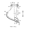
- FIG. 4 is a side view showing the bucket viewed in a direction indicated by an arrow IV in FIG. 3.
- FIG. 5 is a top view showing the bucket as viewed in a direction indicated by an arrow V in FIG. 3.
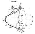
- FIG. 6 is a cross-sectional view showing the bucket as viewed in a direction indicated by an arrow on line VI-VI in FIG. 3. It is a side view showing an example of operation of a bucket at the time of excavation of the ground.
- FIG. 9 is a cross-sectional view illustrating a bucket according to a second embodiment of the present disclosure.
- FIG. 13 is a cross-sectional view illustrating a bucket according to a third embodiment of the present disclosure.
- FIG. 1 is a perspective view illustrating a hydraulic shovel on which a bucket according to Embodiment 1 of the present disclosure is mounted.
- the excavator 100 has a vehicle body 11 and a working machine 12.
- the vehicle body 11 has a revolving superstructure 13 and a traveling device 15.
- the traveling device 15 includes a pair of crawler tracks 15Cr and a traveling motor 15M.
- the hydraulic excavator 100 can travel by rotating the crawler belt 15Cr.
- the traveling motor 15M is provided as a drive source of the traveling device 15. Note that the traveling device 15 may have wheels (tires).
- the revolving unit 13 is provided on the traveling device 15.
- the revolving superstructure 13 is capable of revolving around the revolving center 41 with respect to the traveling device 15.
- the turning center 41 is an axis extending in the up-down direction.
- the revolving superstructure 13 has a cab (operator cab) 14.
- the cab 14 is provided with a driver's seat 14S on which an operator sits. The operator can operate the excavator 100 in the cab 14.
- the revolving unit 13 has an engine room 19 and a counterweight provided at the rear of the revolving unit 13.
- the engine room 19 houses an engine, a hydraulic oil tank, an air cleaner, a hydraulic pump, and the like.
- Work machine 12 is attached to vehicle body 11.
- the work machine 12 is mounted on the revolving superstructure 13.
- the work machine 12 performs work such as excavation of the ground.
- Work implement 12 has boom 16, arm 17, and bucket 50.
- the boom 16 is rotatably connected to the vehicle body 11 (the revolving unit 13) via a boom pin 23.
- the arm 17 is rotatably connected to the boom 16 via an arm pin 24.
- the bucket 50 is rotatably connected to the arm 17 via a bucket pin 25.
- the bucket 50 is rotatably connected to the arm 17 about a central axis 110.
- the bucket pin 25 has a pin shape and extends on the axis of the central shaft 110.
- the central axis 110 is a rotation axis of the bucket 50.
- Work machine 12 further includes boom cylinder 20A and boom cylinder 20B, arm cylinder 21, and bucket cylinder 22.
- the boom cylinder 20A, the boom cylinder 20B, the arm cylinder 21, and the bucket cylinder 22 are hydraulic cylinders driven by hydraulic oil.
- the boom cylinder 20A and the boom cylinder 20B are provided as a pair on both sides of the boom 16 and rotate the boom 16.
- the arm cylinder 21 rotates the arm 17.
- the bucket cylinder 22 rotates the bucket 50.
- the rotation axes of the boom 16, the arm 17, and the bucket 50 extend in parallel with each other.
- the rotation axes of the boom 16, the arm 17, and the bucket 50 all extend in the horizontal direction.
- the hydraulic excavator 100 is of a backhoe type in which the bucket 50 is mounted facing the operator.
- FIG. 4 is a side view showing the bucket viewed in a direction indicated by an arrow IV in FIG.
- FIG. 5 is a top view showing the bucket as viewed in the direction indicated by arrow V in FIG.
- FIG. 6 is a cross-sectional view showing the bucket as viewed in the direction of arrows on line VI-VI in FIG.
- the bucket 50 forms a space for loading an excavated object such as soil.
- the bucket 50 is open in one direction.
- the left-right direction is the direction in which the rotation axis (center axis 110) of the bucket 50 extends.
- the front-back direction is a direction orthogonal to the left-right direction.
- the side on which the pivot axis of the bucket 50 exists is the rear side, and the opposite side is the front side.
- the right side when the bucket 50 is arranged forward is the right side, and the left side when the bucket 50 is arranged forward is the left side.
- the up-down direction is a direction orthogonal to a plane including the front-rear direction and the left-right direction.
- the side where the opening (opening 51) of the bucket 50 exists is the upper side, and the opposite side is the lower side.
- the bucket 50 includes a bottom plate 60, a pair of side plates 81 (81L, 81R), a bracket 86, and a front lip 72.
- the bottom plate 60, the pair of side plates 81 and the front lip 72 are made of a plate material.
- a space for loading an excavated object such as soil is formed.
- the bottom plate 60 faces the opening 51 of the bucket 50.
- the bottom plate 60 is open to the opening 51 in the vertical direction.
- the pair of side plates 81 are provided on both sides of the bottom plate 60 so as to face each other.
- the pair of side plates 81 are connected to both ends of the bottom plate 60 in the left-right direction.
- the side plates 81 are provided in a pair on the left and right.
- the side plate 81L is provided on the left side of the bucket 50.
- the side plate 81R is provided on the right side of the bucket 50.
- the bottom plate 60 is provided in parallel with the rotation axis (center axis 110) of the bucket 50.
- the side plate 81 is provided in a direction intersecting with the rotation axis (center axis 110) of the bucket 50.
- the side plate 81 is provided in a direction orthogonal to the rotation axis (center axis 110) of the bucket 50.
- the length of the bucket 50 in the front-rear direction increases as it approaches the opening edge of the opening 51 in the vertical direction.
- the opening area of the cut portion when the bucket 50 is cut by a plane perpendicular to the vertical direction becomes larger as it approaches the opening edge of the opening portion 51 in the vertical direction.
- the bottom plate 60 has a bottom 61.
- the bottom portion 61 forms a bottom portion of the bottom plate 60 when viewed from the opening 51.
- the bottom portion 61 has a curved shape when viewed from the side of the central axis 110 in the axial direction (the side view shown in FIGS. 3 and 6, hereinafter, also simply referred to as “side view”).
- the bottom portion 61 has a mountain-shaped (arc-shaped) cross section that protrudes downward when cut along a plane perpendicular to the central axis 110.
- the bottom plate 60 has a linear cross section that extends obliquely upward and forward from the front end of the bottom 61 toward the opening edge of the opening 51 when cut along a plane perpendicular to the central axis 110.
- the bottom plate 60 has a linear cross section extending obliquely upward and rearward as a whole from the rear end of the bottom 61 to the opening edge of the opening 51 when cut along a plane perpendicular to the central axis 110.
- the bracket 86 is provided on the back surface (outer surface on the rear side) of the bottom plate 60.
- the bracket 86 is a member for connecting the bucket 50 to the work implement 12 (arm 17) in FIG.
- the bracket 86 is connected to the arm 17 at the center axis 110.
- the bracket 86 has a base 89 and a plurality of plates 87.
- the base 89 is connected to the bottom plate 60 from outside the bucket 50.
- the base 89 has a plate-like shape extending in the left-right direction while having a mountain-shaped cross section projecting rearward from the bottom plate 60.
- the plate 87 is connected to the base 89.
- the plate 87 is made of a plate material whose left-right direction is the thickness direction.
- the plate 87 extends rearward from the base 89.
- the plurality of plates 87 are provided at an interval in the left-right direction.
- the bracket 86 is provided with a hole 88 and a hole 90.
- the hole 88 is provided so as to penetrate the plate 87 in the left-right direction (the thickness direction of the plate 87).
- the hole 88 is provided so as to penetrate the plurality of plates 87 in the left-right direction.
- the hole 88 has a center on the axis of the central axis 110 which is the rotation axis of the bucket 50.
- the hole 88 has a circular opening centered on the central axis 110.
- the hole 90 is provided to penetrate the plate 87 in the left-right direction (the thickness direction of the plate 87).
- the hole 90 is provided so as to penetrate the plurality of plates 87 in the left-right direction.
- the hole 90 has a center on the axis of the central axis 111.
- the hole 90 has a circular opening centered on the central axis 111.
- the central axis 111 extends in parallel with the central axis 110.
- the central axis 111 is located lower than the central axis 110.
- a pin for connecting the bucket 50 to the bucket cylinder 22 in FIG. 1 is inserted into the hole 90.
- the front lip 72 is provided along the opening 51.
- the front lip 72 faces the bracket 86 in the front-rear direction.
- the front lip 72 is connected to a front end of the bottom plate 60.
- the front lip 72 has a certain thickness in a side view and linearly extends obliquely upward and forward.
- the front lip 72 is made of a plate having a certain thickness.
- the front lip 72 has a greater thickness than the bottom plate 60.
- a tooth 76 is connected to the front lip 72 via a tooth adapter 75.
- the bottom plate 60 has a first inclined portion 67 and a second inclined portion 68.
- the first inclined portion 67 and the second inclined portion 68 are provided on the side to which the bracket 86 is attached.
- the first inclined portion 67 is continuous with the bottom portion 61.
- the first inclined portion 67 linearly extends obliquely upward and rearward from the rear end of the bottom portion 61.
- the second inclined section 68 is connected to the first inclined section 67.
- the second inclined portion 68 is provided along the opening 51.
- the second inclined portion 68 is bent from the first inclined portion 67 and extends to the opening edge of the opening 51.
- the second inclined portion 68 has a different inclination from the first inclined portion 67, and linearly extends obliquely upward and rearward from the first inclined portion 67.
- the bottom plate 60 has a bent shape that is bent at the boundary between the first inclined portion 67 and the second inclined portion 68 in a side view.
- the side plates 81 are connected to both ends of the bottom plate 60 in the axial direction of the central shaft 110.
- the side plate 81 is made of a plate material whose thickness direction is in the left-right direction (the axial direction of the central axis 110).
- the side plate 81 has a side lip 82.
- the side lip 82 is provided along the opening 51.
- the side lip 82 is provided at the same height as the front lip 72 in the vertical direction.
- the side lip 82 is made of a plate having a certain thickness.
- the side lip 82 has a thickness greater than the thickness of the other part of the side plate 81.
- a side cutter 77 is fixed to the side lip 82.
- the side cutter 77 is provided at a position closer to the front lip 72 than the bracket 86 in the front-rear direction.
- a reinforcing member 91 is provided at a corner between the side plate 81 (81L, 81R) and the bottom plate 60.
- the reinforcing member 91 is provided in the bucket 50.
- the reinforcing member 91 is provided between the first inclined portion 67 and the second inclined portion 68.
- the front lip 72, the side lip 82 of the side plate 81L, the first inclined portion 67, and the side lip 82 of the side plate 81R are provided so as to surround the opening 51.
- the first inclined portion 67 is provided below the front lip 72, the side lip 82, and the first inclined portion 67.
- a first reference straight line 121 passing through the central axis 110 (the center of the hole 88) and the front end 73 of the front lip 72 is defined.
- the tip 73 defines an opening edge of the opening 51 on the front side of the bucket 50.
- the tip 73 is the tip (upper end) of the front lip 72 as viewed from the bottom 61.
- the front end 73 is a portion of the front lip 72 located at the uppermost position.
- the length H from the first reference straight line 121 to the bottom plate 60 changes along the linear direction of the first reference straight line 121.
- the bottom plate 60 has a first deepest portion (corresponding to “the deepest portion” in claim 1) 62.
- the first deepest part 62 is a part of the bottom part 61.
- the length H from the first reference straight line 121 to the bottom plate 60 is the largest value (Hmax) at the first deepest portion 62.
- the first deepest portion 62 is a portion where the depth in the bucket 50 is the largest with respect to the first reference straight line 121.
- a second reference straight line 122 that is orthogonal to the first reference straight line 121 and passes through the first deepest portion 62 is defined.
- Hmax corresponds to the length of the second reference straight line 122 from the first reference straight line 121 to the first deepest part 62.
- the length H from the first reference straight line 121 to the bottom plate 60 decreases in the linear direction of the first reference straight line 121 from the first deepest portion 62 toward the front and decreases from the first deepest portion 62 toward the rear. .
- the angle ⁇ formed by the second reference straight line 122 and the front lip 72 is smaller than the angle ⁇ formed by the second reference straight line 122 and the first inclined portion 67 ( ⁇ ⁇ ). In other words, the angle ⁇ formed by the second reference straight line 122 and the first inclined portion 67 is larger than the angle ⁇ formed by the second reference straight line 122 and the front lip 72.
- the angle ⁇ is in the range of more than 20 ° and 45 ° or less (20 ° ⁇ ⁇ 45 °).
- the angle ⁇ is in the range of 20 ° or less ( ⁇ ⁇ 20 °).
- the angle ⁇ is in the range of 30 ° to 40 ° (30 ° ⁇ ⁇ ⁇ 40 °)
- the angle ⁇ is in the range of less than 30 °.
- the sum of the angles ⁇ and ⁇ is in the range of more than 50 ° and 60 ° or less (50 ° ⁇ + ⁇ ⁇ 60 °).
- the angle ⁇ formed by the second reference straight line 122 and the second inclined portion 68 is smaller than the angle ⁇ formed by the second reference straight line 122 and the first inclined portion 67 ( ⁇ ⁇ ).
- the angle ⁇ formed by the second reference straight line 122 and the second inclined portion 68 is smaller than the angle ⁇ formed by the second reference straight line 122 and the front lip 72 ( ⁇ ⁇ ).
- the angle ⁇ is in a range from 15 ° to 20 °. (15 ° ⁇ ⁇ ⁇ 20 °).
- the angle ⁇ formed by the second reference straight line 122 and the second inclined portion 68 may be equal to or larger than the angle ⁇ formed by the second reference straight line 122 and the front lip 72 ( ⁇ ⁇ ⁇ ).
- the position of the intersection P between the first reference straight line 121 and the second reference straight line 122 is near the front lip 72 on the first reference straight line 121.
- the intersection P of the first reference straight line 121 and the second reference straight line 122 is located on the first reference straight line 121 at a position closer to the front lip 72 than the center axis 110.
- the length Lb of the first reference straight line 121 from the intersection P of the first reference straight line 121 and the second reference straight line 122 to the tip 73 of the front lip 72 is centered from the intersection P of the first reference straight line 121 and the second reference straight line 122. It is smaller than the length La to the axis 110 (Lb ⁇ La).
- the volume of the bucket 50 on the rear side with respect to the second reference straight line 122 is larger than the volume of the bucket 50 on the front side with the second reference straight line 122 therebetween.
- the capacity of the bucket 50 on the rear side with respect to the second reference straight line 122 may be equal to or smaller than the capacity of the bucket 50 on the front side with respect to the second reference straight line 122.
- the side plate 81 (81L, 81R) has a side end 85.
- the side end 85 defines an opening edge of the opening 51 on the right and left sides of the bucket 50.
- the side end 85 is a tip (upper end) portion of the side plate 81 (side lip 82) as viewed from the bottom 61.
- the ⁇ side end portion 85 is provided with a concave portion 83.
- the concave portion 83 has a shape that is concave in a direction approaching the bottom plate 60 in a side view.
- the recess 83 is provided on both the front and rear sides with the second reference straight line 122 interposed therebetween.
- the recess 83 is provided at a position avoiding the side cutter 77.
- the length h from the first reference straight line 121 to the recess 83 changes along the linear direction of the first reference straight line 121.
- the concave portion 83 has a second deepest portion 84.
- the length h from the first reference straight line 121 to the recess 83 becomes the largest value (hmax) in the second deepest part 84.
- the second deepest portion 84 is a portion where the amount of depression of the concave portion 83 is largest with respect to the first reference straight line 121.
- the second deepest part 84 is located on the second reference straight line 122.
- hmax corresponds to the length of the second reference straight line 122 from the first reference straight line 121 to the second deepest part 84.
- the length h from the first reference straight line 121 to the concave portion 83 decreases in the straight line direction of the first reference straight line 121 from the second deepest portion 84 toward the front and decreases from the second deepest portion 84 toward the rear. Become.
- the bottom plate 60 has a curved shape having a curvature 1 / R (radius of curvature R) at the first deepest portion 62.
- the concave portion 83 has a curved shape having a curvature 1 / r (curvature radius r) at the second deepest portion 84.
- the curvature 1 / r of the concave portion 83 in the second deepest portion 84 is equal to or greater than the curvature 1 / R of the bottom plate 60 in the first deepest portion 62 (1 / r ⁇ 1 / R).
- the curvature 1 / r of the recess 83 in the second deepest part 84 may be smaller than the curvature 1 / R of the bottom plate 60 in the first deepest part 62 (1 / r ⁇ 1 / R).
- FIG. 7 is a side view showing an example of the operation of the bucket when excavating the ground. As shown in FIGS. 1 and 7, by driving the boom cylinders 20A and 20B, the arm cylinder 21, and the bucket cylinder 22, the boom 16, the arm 17, and the bucket 50 are rotated to excavate (groove) the ground. ).
- the solid line 131 represents the ground before excavation
- the two-dot chain line 132 represents the ground after excavation.
- the tip of the tooth 76 is brought into contact with the ground (bucket 50A).
- the bucket 50 is caused to penetrate the ground by rotating the bucket 50 about the central axis 110 with the tooth 76 at the top (bucket 50B).
- the bucket 50 is horizontally moved in a direction approaching the cab 14 by rotating the boom 16 and the arm 17 while rotating the bucket 50 about the central axis 110 (bucket 50C). Thereafter, the bucket 50 is lifted from the ground with the excavated soil loaded in the bucket 50.
- the bucket 50 takes a posture in which the first reference straight line 121 is in the vertical direction and the second reference straight line 122 is in the horizontal direction during the horizontal movement as shown by the bucket 50C in FIG. At this time, the front lip 72 and the front side of the bottom plate 60 travel underground below the ground, and the rear side of the bottom plate 60 travels above the ground.
- the angle ⁇ formed by the second reference straight line 122 and the front lip 72 is smaller than the angle ⁇ formed by the second reference straight line 122 and the first inclined portion 67.
- the angle formed by the direction of travel is suppressed to a smaller value. Accordingly, when the front lip 72 and the front side of the bottom plate 60 travel underground, soil can efficiently enter the bucket 50 through the front lip 72 as shown by the arrow 141.
- the length Lb of the first reference straight line 121 from the intersection P of the first reference straight line 121 and the second reference straight line 122 to the tip 73 of the front lip 72 is the intersection P of the first reference straight line 121 and the second reference straight line 122. From the center axis 110 to the center axis 110.
- the soil that has entered the bucket 50 is It is easy to be carried from the front lip 72 toward the first deepest portion 62.
- the soil in the form rising at a repose angle ⁇ from the ground forms an area 52 directly below the first inclined portion 67 in the bucket 50.
- the entry of the soil into the region 52 may be hindered by the first inclined portion 67.
- the angle ⁇ formed by the second reference straight line 122 and the first inclined portion 67 is larger than the angle ⁇ formed by the second reference straight line 122 and the front lip 72. The inclination does not become too small.
- the soil in the form rising from the ground can efficiently enter the region 52.
- the amount of soil loaded on the bucket 50 can be increased, and efficient excavation can be performed.
- the relationship between the inclination of the first inclined portion 67 and the angle of repose ⁇ formed by the soil rising from the ground will be described.
- the entire area 52 becomes Not filled with soil, which can result in dead space in bucket 50 that is not filled with soil when bucket 50 is lifted from the ground.
- the inclination of the first inclined portion 67 is smaller than the angle of repose ⁇ , the soil may not be able to efficiently enter the region 52 due to the resistance received from the first inclined portion 67.
- the angle ⁇ formed by the second reference straight line 122 and the first inclined portion 67 in a range of more than 20 ° and 45 ° or less, more preferably in a range of 30 ° or more and 40 ° or less.
- the inclination of the first inclined portion 67 can be made closer to the angle of repose ⁇ .
- the angle ⁇ formed by the second reference straight line 122 and the second inclined portion 68 is smaller than the angle formed by the second reference straight line 122 and the first inclined portion 67. Accordingly, the soil enters the region 53 immediately below the second inclined portion 68 in the bucket 50 so as to fill the entire region 53, so that it is possible to more reliably prevent a dead space from being generated in the bucket 50.
- the side plate 81 needs to penetrate the ground while pushing back the soil, so that the side plate 81 may cause an increase in resistance (penetration resistance) when the bucket 50 penetrates.
- the concave portion 83 is provided at the side end portion 85 of the side plate 81, the length of the side plate 81 that goes underground can be reduced. Thus, it is possible to suppress an increase in the penetration resistance caused by the side plate 81 and improve the penetration of the bucket 50 into the ground.
- the side plate 81 on the second reference straight line 122 has a lower penetration resistance. It has the largest effect on growth.
- the concave portion 83 has the second deepest portion 84 on the second reference straight line 122, the length of the side plate 81 on the second reference straight line 122 can be reduced. Thereby, the above-described effect of suppressing an increase in the penetration resistance caused by the side plate 81 can be more effectively exerted.
- the magnitude of the penetration resistance caused by the side plate 81 is different between when the side plate 81 on the second reference straight line 122 penetrates the ground and when the side plate 81 at a position shifted in the front-rear direction from the second reference straight line 122 is on the ground. Excessive fluctuation can be suppressed between the time of intrusion. Thereby, the ground excavation work can be performed more smoothly.
- the curvature 1 / r of the second deepest portion 84 is equal to or greater than the curvature 1 / R of the first deepest portion 62.
- the amount of depression of the concave portion 83 in the second deepest portion 84 can be set to be larger, so that the length of the side plate 81 on the second reference straight line 122 passing through the first deepest portion 62 Can be more effectively shortened. Thereby, the penetration of the bucket 50 into the ground can be further improved.
- the curvature 1 / r of the second deepest portion 84 may be equal to or less than the curvature 1 / R of the first deepest portion 62. In this case, it is possible to effectively suppress an increase in the penetration resistance due to the side plate 81 in a wider range at a position shifted in the front-rear direction from the second reference straight line 122.
- the bucket 50 is connected to the arm 17 of the work machine 12 so as to be rotatable around a central axis 110 as a predetermined axis.
- the bucket 50 includes a bottom plate 60, a pair of side plates 81, a bracket 86, and a front lip 72.
- the bottom plate 60 faces the opening 51 of the bucket 50.
- the pair of side plates 81 are provided on both sides of the bottom plate 60 so as to face each other.
- the bracket 86 is provided on the back surface of the bottom plate 60.
- the bracket 86 is connected to the arm 17 at the center axis 110.
- the front lip 72 is provided along the opening 51.
- the bottom plate 60 has a first inclined portion 67 on the side where the bracket 86 is attached.
- the bottom plate 60 further has a first deepest portion 62 as the deepest portion.
- the first deepest portion 62 has the largest length from the first reference straight line 121 passing through the center axis 110 and the front end 73 of the front lip 72 to the bottom plate 60.
- the angle ⁇ formed by the front lip 72 and the second reference straight line 122 orthogonal to the first reference straight line 121 and passing through the first deepest portion 62 is the angle ⁇ formed by the second reference straight line 122 and the first inclined portion 67. Less than.
- the position of the intersection P between the first reference straight line 121 and the second reference straight line 122 is located near the front lip 72 on the first reference straight line 121.
- the angle ⁇ formed by the second reference straight line 122 and the front lip 72 is smaller than the angle ⁇ formed by the second reference straight line 122 and the first inclined portion 67. It is possible to efficiently enter the bucket 50 through the lip 72. Further, since the position of the intersection P between the first reference straight line 121 and the second reference straight line 122 is near the front lip 72 on the first reference straight line 121, the soil that has entered the bucket 50 is removed from the front lip 72 by the first lip 72. It is easy to be carried toward the deepest part 62.
- the soil is transferred to the region 52 immediately below the first inclined portion 67. It can be entered efficiently.
- the amount of soil loaded on the bucket 50 can be increased, and efficient excavation can be performed.
- the angle formed by the second reference straight line 122 and the first inclined portion 67 is in a range of more than 20 ° and 45 ° or less.
- the angle formed by the second reference straight line 122 and the first inclined portion 67 is in a range of 30 ° or more and 40 ° or less.
- the inclination of the first inclined portion 67 can be made closer to the angle of repose ⁇ of the soil rising from the ground. This allows the soil to more efficiently enter the region 52 immediately below the first inclined portion 67.
- the bottom plate 60 further has a second inclined portion 68.
- the second inclined portion 68 is connected to the first inclined portion 67.
- the second inclined portion 68 is provided along the opening 51.
- the angle ⁇ formed by the second reference straight line 122 and the second inclined portion 68 is smaller than the angle ⁇ formed by the second reference straight line 122 and the first inclined portion 67.
- the soil can enter the area 53 immediately below the second inclined portion 68 so as to fill the entire area. This can prevent a dead space from being generated in the bucket 50 when the bucket 50 is raised.
- the side plate 81 has a side end 85.
- the side end 85 defines an opening edge of the opening 51.
- the side end 85 is provided with a recess 83.
- the recess 83 is recessed in a direction approaching the bottom plate 60 in a side view as viewed in the axial direction of the central axis 110.
- the excavator 100 includes a vehicle body 11 and a work machine 12.
- Work implement 12 is attached to vehicle body 11.
- Work implement 12 has boom 16, arm 17, and bucket 50.
- the boom 16 is rotatably connected to the vehicle body 11.
- the arm 17 is rotatably connected to the boom 16.
- the bucket 50 is rotatably connected to the arm 17.
- the excavator 100 can perform more efficient excavation by increasing the amount of soil loaded on the bucket 50.
- FIG. 8 is a cross-sectional view illustrating a bucket according to the second embodiment of the present disclosure.
- FIG. 8 is a diagram corresponding to FIG. 6 in the first embodiment.
- the bucket according to the present embodiment has basically the same structure as the bucket 50 according to the first embodiment. Hereinafter, the description of the overlapping structure will not be repeated.
- the bucket in the present embodiment has a bottom plate 60, a pair of side plates 81, a bracket 86, and a front lip 72.
- the bottom plate 60 has a first inclined portion 67. Bottom plate 60 does not have second inclined portion 68 in the first embodiment.
- the angle ⁇ formed by the second reference straight line 122 and the front lip 72 is smaller than the angle ⁇ formed by the second reference straight line 122 and the first inclined portion 67 ( ⁇ ⁇ ).
- the angle ⁇ is in the range of more than 20 ° and 45 ° or less (20 ° ⁇ ⁇ 45 °)
- the angle ⁇ is in the range of 20 ° or less ( ⁇ ⁇ 20 °).
- the position of the intersection P between the first reference straight line 121 and the second reference straight line 122 is near the front lip 72 on the first reference straight line 121.
- the length Lb of the first reference straight line 121 from the intersection P of the first reference straight line 121 and the second reference straight line 122 to the tip 73 of the front lip 72 is centered from the intersection P of the first reference straight line 121 and the second reference straight line 122. It is smaller than the length La to the axis 110 (Lb ⁇ La).
- FIG. 9 is a cross-sectional view illustrating a bucket according to the third embodiment of the present disclosure.
- FIG. 9 is a diagram corresponding to FIG. 6 in the first embodiment.
- the bucket according to the present embodiment has basically the same structure as the bucket 50 according to the first embodiment. Hereinafter, the description of the overlapping structure will not be repeated.
- the bucket according to the present embodiment includes a bottom plate 60, a pair of side plates 81, a bracket 86, and a front lip 72.
- the bottom portion 61 of the bottom plate 60 has a curved shape in front of the second reference straight line 122.
- the bottom portion 61 has a bent shape in which two straight lines having different inclinations are connected behind the second reference straight line 122.
- the first deepest portion 62 of the bottom plate 60 forms a corner protruding downward.
- the second deepest portion 84 of the concave portion 83 is provided at a position shifted from the second reference straight line 122 in the straight line direction of the first reference straight line 121.
- the second deepest portion 84 is provided ahead of the second reference straight line 122 in the direction of the first reference straight line 121.
- the second deepest portion 84 has a triangular cutout shape.
- the side lip 82 is not provided with the side cutter 77 according to the first embodiment.
- the angle ⁇ formed by the second reference straight line 122 and the front lip 72 is smaller than the angle ⁇ formed by the second reference straight line 122 and the first inclined portion 67 ( ⁇ ⁇ ).
- the angle ⁇ is in the range of more than 20 ° and 45 ° or less (20 ° ⁇ ⁇ 45 °)
- the angle ⁇ is in the range of 20 ° or less ( ⁇ ⁇ 20 °).
- the angle ⁇ is in the range of 30 ° to 40 ° (30 ° ⁇ ⁇ ⁇ 40 °)
- the angle ⁇ is in the range of less than 30 °.
- the sum of the angles ⁇ and ⁇ is in the range of more than 50 ° and 60 ° or less (50 ° ⁇ + ⁇ ⁇ 60 °).
- the position of the intersection P between the first reference straight line 121 and the second reference straight line 122 is near the front lip 72 on the first reference straight line 121.
- the length Lb of the first reference straight line 121 from the intersection P of the first reference straight line 121 and the second reference straight line 122 to the tip 73 of the front lip 72 is centered from the intersection P of the first reference straight line 121 and the second reference straight line 122. It is smaller than the length La to the axis 110 (Lb ⁇ La).
- the present disclosure is applied to a bucket mounted on a work vehicle.
Landscapes
- Engineering & Computer Science (AREA)
- Mechanical Engineering (AREA)
- Mining & Mineral Resources (AREA)
- Civil Engineering (AREA)
- General Engineering & Computer Science (AREA)
- Structural Engineering (AREA)
- Shovels (AREA)
Abstract
バケット(50)は、作業機(12)のアーム(17)に中心軸(110)を中心に回動可能に連結される。バケット(50)は、第1最深部(62)を有する底板(60)と、底板(60)の背面に設けられるブラケット(86)と、フロントリップ(72)とを備える。底板(60)は、ブラケット(86)が取り付けられる側に第1傾斜部(67)を有する。中心軸(110)およびフロントリップ(72)の先端(73)を通る第1基準直線(121)と、第1基準直線(121)と直交し、第1最深部(62)を通る第2基準直線(122)とを規定する。第2基準直線(122)とフロントリップ(72)とがなす角度(β)は、第2基準直線(122)と第1傾斜部(67)とがなす角度(α)よりも小さい。第1基準直線(121)と第2基準直線(122)との交点(P)の位置は、第1基準直線(121)上のフロントリップ(72)寄りにある。
Description
本開示は、バケットおよび作業車両に関する。
たとえば、国際公開第2004/023001号(特許文献1)には、建設機械用のバケットが開示されている。
上述の特許文献1に開示されるように、油圧ショベルなどの作業車両に搭載され、地面の掘削などを行なうバケットが知られている。このようなバケットにおいては、バケット内に積み込む土量を増やして、効率的な掘削が行なうことが求められる。
本開示の目的は、効率的な掘削を行なうことが可能なバケットと、そのようなバケットを備える作業車両とを提供することである。
本開示に従ったバケットは、作業機のアームに所定軸を中心に回動可能に連結されるバケットである。バケットは、底板と、一対の側板と、ブラケットと、フロントリップとを備える。底板は、バケットの開口部に対向する。一対の側板は、底板の両側に互いに対向して設けられる。ブラケットは、底板の背面に設けられる。ブラケットは、所定軸においてアームと連結される。フロントリップは、開口部に沿って設けられる。底板は、ブラケットが取り付けられる側に第1傾斜部を有する。底板は、最深部をさらに有する。最深部は、所定軸およびフロントリップの先端を通る第1基準直線から底板までの長さが最も大きくなる。第1基準直線と直交し、最深部を通る第2基準直線と、フロントリップとがなす角度は、第2基準直線と、第1傾斜部とがなす角度よりも小さい。第1基準直線および第2基準直線の交点の位置は、第1基準直線上のフロントリップ寄りにある。
本開示に従った作業車両は、車両本体と、作業機とを備える。作業機は、車両本体に取り付けられる。作業機は、ブームと、アームと、上述のバケットとを有する。ブームは、車両本体に回動可能に連結される。アームは、ブームに回動可能に連結される。バケットは、アームに回動可能に連結される。
本開示に従えば、効率的な掘削を行なうことが可能なバケットと、そのようなバケットを備える作業車両とを提供することができる。
本開示の実施の形態について、図面を参照して説明する。なお、以下で参照する図面では、同一またはそれに相当する部材には、同じ番号が付されている。
(実施の形態1)
図1は、本開示の実施の形態1におけるバケットを搭載した油圧ショベルを示す斜視図である。図1に示されるように、油圧ショベル100は、車両本体11と、作業機12とを有する。車両本体11は、旋回体13と、走行装置15とを有する。
図1は、本開示の実施の形態1におけるバケットを搭載した油圧ショベルを示す斜視図である。図1に示されるように、油圧ショベル100は、車両本体11と、作業機12とを有する。車両本体11は、旋回体13と、走行装置15とを有する。
走行装置15は、一対の履帯15Crと、走行モータ15Mとを有する。油圧ショベル100は、履帯15Crの回転により走行可能である。走行モータ15Mは、走行装置15の駆動源として設けられている。なお、走行装置15が車輪(タイヤ)を有してもよい。
旋回体13は、走行装置15上に設けられている。旋回体13は、旋回中心41を中心として、走行装置15に対して旋回可能である。旋回中心41は、上下方向に延びる軸である。旋回体13は、キャブ(運転室)14を有する。キャブ14には、オペレータが着座する運転席14Sが設けられている。オペレータは、キャブ14において油圧ショベル100を操作可能である。
旋回体13は、エンジンルーム19と、旋回体13の後部に設けられるカウンタウェイトとを有する。エンジンルーム19には、エンジン、作動油タンク、エアクリーナおよび油圧ポンプなどが収容されている。
作業機12は、車両本体11に取り付けられている。作業機12は、旋回体13に取り付けられている。作業機12は、地面の掘削などの作業を行なう。作業機12は、ブーム16と、アーム17と、バケット50とを有する。
ブーム16は、ブームピン23を介して、車両本体11(旋回体13)に回動可能に連結されている。アーム17は、アームピン24を介して、ブーム16に回動可能に連結されている。バケット50は、バケットピン25を介して、アーム17に回動可能に連結されている。バケット50は、中心軸110を中心にして、アーム17に回動可能に連結されている。バケットピン25は、ピン形状を有し、中心軸110の軸上で延びている。中心軸110は、バケット50の回動軸である。
作業機12は、ブームシリンダ20Aおよびブームシリンダ20Bと、アームシリンダ21と、バケットシリンダ22とをさらに有する。
ブームシリンダ20A、ブームシリンダ20B、アームシリンダ21およびバケットシリンダ22は、作動油によって駆動される油圧シリンダである。ブームシリンダ20Aおよびブームシリンダ20Bは、ブーム16の両側に一対に設けられており、ブーム16を回動動作させる。アームシリンダ21は、アーム17を回動動作させる。バケットシリンダ22は、バケット50を回動動作させる。
ブーム16、アーム17およびバケット50の回動軸は、互いに平行に延びている。ブーム16、アーム17およびバケット50の回動軸は、いずれも、水平方向に延びている。
油圧ショベル100は、バケット50がオペレータの側を向いて取り付けられるバックホウタイプである。
続いて、バケット50の構造について詳細に説明する。図2および図3は、バケットを示す斜視図である。図4は、図3中の矢印IVに示す方向に見たバケットを示す側面図である。図5は、図3中の矢印Vに示す方向に見たバケットを示す上面図である。図6は、図3中のVI-VI線上の矢視方向に見たバケットを示す断面図である。
図2から図6に示されるように、バケット50は、土などの被掘削物を積み込むための空間を形成する。バケット50は、一方向において開口している。
以下のバケット50の構造の説明において、左右方向は、バケット50の回動軸(中心軸110)が延びる方向である。前後方向は、左右方向と直交する方向である。バケット50の回動軸が存在する側が、後方であり、その反対側が、前方である。バケット50を前方に向けて配置したときの右側が、右方であり、バケット50を前方に向けて配置したときの左側が、左方である。上下方向とは、前後方向および左右方向を含む平面に直交する方向である。バケット50の開口(開口部51)が存在する側が、上方であり、その反対側が、下方である。これらの方向は、バケット50が土砂等の被掘削物を積み込んだ状態で引き上げられた時の姿勢を基準にして、規定されている。
バケット50は、底板60と、一対の側板81(81L,81R)と、ブラケット86と、フロントリップ72とを有する。底板60、一対の側板81およびフロントリップ72は、板材から構成されている。底板60、一対の側板81およびフロントリップ72に囲まれた位置に、土などの被掘削物を積み込むための空間が形成されている。
底板60は、バケット50の開口部51に対向している。底板60は、上下方向において、開口部51に開口している。一対の側板81は、底板60の両側に互いに対向して設けられている。一対の側板81は、左右方向における底板60の両端に接続されている。側板81は、左右一対に設けられている。側板81Lは、バケット50の左方に設けられている。側板81Rは、バケット50の右方に設けられている。
底板60は、バケット50の回動軸(中心軸110)と平行に設けられている。側板81は、バケット50の回動軸(中心軸110)と交わる方向に設けられている。側板81は、バケット50の回動軸(中心軸110)と直交する方向に設けられている。
前後方向におけるバケット50の長さは、上下方向において開口部51の開口縁に近づくほど大きくなる。上下方向に直交する平面によりバケット50が切断された場合の切断部の開口面積は、上下方向において開口部51の開口縁に近づくほど大きくなる。
底板60は、底部61を有する。底部61は、開口部51から見た場合の底板60の底部分を構成している。底部61は、中心軸110の軸方向に見た側面視(図3および図6に示される側面視であり、以下では、単に「側面視」ともいう)において、湾曲形状を有する。底部61は、中心軸110に直交する平面により切断された場合に、下方に向けて突出する山形(円弧形状)の断面を有する。
底板60は、中心軸110に直交する平面により切断された場合に、底部61の前方側の端部から開口部51の開口縁に向けて、斜め上前方に延びる直線形状の断面を有する。底板60は、中心軸110に直交する平面により切断された場合に、底部61の後方側の端部から開口部51の開口縁まで、全体として斜め上後方に延びる直線形状の断面を有する。
ブラケット86は、底板60の背面(後方側の外表面)に設けられている。ブラケット86は、バケット50を、図1中の作業機12(アーム17)に連結するための部材である。ブラケット86は、中心軸110においてアーム17と連結される。
ブラケット86は、基台89と、複数のプレート87とを有する。基台89は、バケット50の外側から底板60に接続されている。基台89は、底板60から後方に向けて突出する山形の断面を有しながら、左右方向に板状に延在している。プレート87は、基台89に接続されている。プレート87は、左右方向が厚み方向となる板材からなる。プレート87は、基台89から後方に向けて延出している。複数のプレート87は、左右方向において、互いに間隔を隔てて設けられている。
ブラケット86には、孔88と、孔90とが設けられている。孔88は、プレート87を、左右方向(プレート87の厚み方向)において貫通するように設けられている。孔88は、複数のプレート87を、左右方向に貫くように設けられている。孔88は、バケット50の回動軸である中心軸110の軸上に中心を有する。孔88は、中心軸110を中心とする円形の開口を有する。孔88にバケットピン25が挿入されることによって、バケット50は、アーム17に対して、中心軸110を中心に回動可能に連結されている(図1も参考のこと)。
孔90は、プレート87を、左右方向(プレート87の厚み方向)において貫通するように設けられている。孔90は、複数のプレート87を、左右方向に貫くように設けられている。孔90は、中心軸111の軸上に中心を有する。孔90は、中心軸111を中心とする円形の開口を有する。中心軸111は、中心軸110と平行に延びている。中心軸111は、中心軸110よりも下方に位置している。孔90には、バケット50を図1中のバケットシリンダ22に連結するためのピンが挿入される。
フロントリップ72は、開口部51に沿って設けられている。フロントリップ72は、前後方向においてブラケット86と対向している。フロントリップ72は、底板60の前方側の端部に接続されている。フロントリップ72は、側面視において、一定の厚みを有しながら、斜め上前方に直線状に延びている。フロントリップ72は、一定の厚みを有する板材から構成されている。フロントリップ72は、底板60よりも大きい厚みを有する。フロントリップ72には、ツースアダプタ75を介して、ツース76が接続されている。
底板60は、第1傾斜部67と、第2傾斜部68とを有する。第1傾斜部67および第2傾斜部68は、ブラケット86が取り付けられる側に設けられている。第1傾斜部67は、底部61に連なっている。第1傾斜部67は、底部61の後方側の端部から斜め上後方に直線状に延びている。第2傾斜部68は、第1傾斜部67に連なっている。第2傾斜部68は、開口部51に沿って設けられている。第2傾斜部68は、第1傾斜部67から折れ曲がり、開口部51の開口縁まで延びている。第2傾斜部68は、第1傾斜部67とは異なる傾きで、第1傾斜部67から斜め上後方に直線状に延びている。底板60は、側面視において、第1傾斜部67および第2傾斜部68の境界で折れ曲がった折れ曲がり形状を有する。
側板81は、中心軸110の軸方向における底板60の両端に接続されている。側板81は、左右方向(中心軸110の軸方向)が厚み方向となる板材により構成されている。
側板81は、サイドリップ82を有する。サイドリップ82は、開口部51に沿って設けられている。サイドリップ82は、上下方向において、フロントリップ72と同じ高さに設けられている。サイドリップ82は、一定の厚みを有する板材から構成されている。サイドリップ82は、側板81の他部位の厚みよりも大きい厚みを有する。サイドリップ82には、サイドカッタ77が固定されている。サイドカッタ77は、前後方向において、ブラケット86よりもフロントリップ72に寄った位置に設けられている。
側板81(81L,81R)と、底板60との隅部には、補強部材91が設けられている。補強部材91は、バケット50内に設けられている。補強部材91は、第1傾斜部67および第2傾斜部68の間に渡って設けられている。
フロントリップ72、側板81Lのサイドリップ82、第1傾斜部67および側板81Rのサイドリップ82は、開口部51を取り囲むように設けられている。第1傾斜部67は、フロントリップ72、サイドリップ82および第1傾斜部67よりも下方に設けられている。
図6に示されるように、中心軸110(孔88の中心)と、フロントリップ72の先端73とを通る第1基準直線121が規定されている。先端73は、バケット50の前側において開口部51の開口縁を規定している。先端73は、底部61から見た場合のフロントリップ72の先端(上端)部分である。先端73は、フロントリップ72のうちで最も上方に位置する部分である。
第1基準直線121から底板60までの長さHは、第1基準直線121の直線方向に沿って変化する。
底板60は、第1最深部(請求項1中の「最深部」に対応)62を有する。第1最深部62は、底部61の一部分である。第1基準直線121から底板60までの長さHは、第1最深部62において最も大きい値(Hmax)となる。第1最深部62は、第1基準直線121を基準にして、バケット50内の深さが最も大きくなる部分である。
第1基準直線121と直交し、第1最深部62を通る第2基準直線122が規定されている。Hmaxは、第1基準直線121から第1最深部62までの第2基準直線122の長さに対応する。第1基準直線121から底板60までの長さHは、第1基準直線121の直線方向において、第1最深部62から前方に向かうほど小さくなり、第1最深部62から後方に向かうほど小さくなる。
第2基準直線122およびフロントリップ72がなす角度βは、第2基準直線122および第1傾斜部67がなす角度αよりも小さい(β<α)。言い換えれば、第2基準直線122および第1傾斜部67がなす角度αは、第2基準直線122およびフロントリップ72がなす角度βよりも大きい。
角度αが、20°を超え45°以下の範囲であるとき(20°<α≦45°)、角度βは、20°以下の範囲である(β≦20°)。角度αが、30°以上40°以下の範囲であるとき(30°≦α≦40°)、角度βは、30°未満の範囲である。角度αおよび角度βの和は、50°を超え60°以下の範囲である(50°<α+β≦60°)。
第2基準直線122および第2傾斜部68がなす角度γは、第2基準直線122および第1傾斜部67がなす角度αよりも小さい(γ<α)。第2基準直線122および第2傾斜部68がなす角度γは、第2基準直線122およびフロントリップ72がなす角度βよりも小さい(γ<β)。角度γは、15°以上20°以下の範囲である。(15°≦γ≦20°)。
なお、第2基準直線122および第2傾斜部68がなす角度γは、第2基準直線122およびフロントリップ72がなす角度β以上であってもよい(γ≧β)。
第1基準直線121および第2基準直線122の交点Pの位置は、第1基準直線121上のフロントリップ72寄りにある。第1基準直線121および第2基準直線122の交点Pは、第1基準直線121上において、中心軸110よりもフロントリップ72寄りの位置にある。第1基準直線121および第2基準直線122の交点Pからフロントリップ72の先端73までの第1基準直線121の長さLbは、第1基準直線121および第2基準直線122の交点Pから中心軸110までの長さLaよりも小さい(Lb<La)。
第2基準直線122を挟んで後方側のバケット50の容積は、第2基準直線122を挟んで前方側のバケット50の容積よりも大きい。第2基準直線122を挟んで後方側のバケット50の容積は、第2基準直線122を挟んで前方側のバケット50の容積以下であってもよい。
図2から図6に示されるように、側板81(81L,81R)は、側端部85を有する。側端部85は、バケット50の右側および左側において開口部51の開口縁を規定している。側端部85は、底部61から見た場合の側板81(サイドリップ82)の先端(上端)部分である。
側端部85には、凹み部83が設けられている。凹み部83は、側面視において、底板60に近づく方向に凹む形状を有する。凹み部83は、第2基準直線122を挟んで前方および後方の両側に渡って設けられている。凹み部83は、サイドカッタ77を避けた位置に設けられている。
図6に示されるように、第1基準直線121から凹み部83までの長さhは、第1基準直線121の直線方向に沿って変化する。
凹み部83は、第2最深部84を有する。第1基準直線121から凹み部83までの長さhは、第2最深部84において最も大きい値(hmax)となる。第2最深部84は、第1基準直線121を基準にして、凹み部83の凹み量が最も大きくなる部分である。
第2最深部84は、第2基準直線122上に位置している。hmaxは、第1基準直線121から第2最深部84までの第2基準直線122の長さに対応する。第1基準直線121から凹み部83までの長さhは、第1基準直線121の直線方向において、第2最深部84から前方に向かうほど小さくなり、第2最深部84から後方に向かうほど小さくなる。
底板60は、第1最深部62において、曲率1/R(曲率半径R)を有する湾曲形状を有する。凹み部83は、第2最深部84において、曲率1/r(曲率半径r)を有する湾曲形状を有する。第2最深部84における凹み部83の曲率1/rは、第1最深部62における底板60の曲率1/R以上である(1/r≧1/R)。第2最深部84における凹み部83の曲率1/rは、第1最深部62における底板60の曲率1/Rよりも小さくてもよい(1/r<1/R)。
図7は、地面の掘削時におけるバケットの動作の一例を示す側面図である。図1および図7に示されるように、ブームシリンダ20A,20B、アームシリンダ21およびバケットシリンダ22の駆動により、ブーム16、アーム17およびバケット50を回動動作させることによって、地面の掘削(溝掘り)を行なう。
図7中では、実線131により、掘削前の地面が表わされ、2点鎖線132により、掘削後の地面が表わされている。掘削の進行に伴って、バケット50は、バケット50A、バケット50Bおよびバケット50Cに示す位置を順に移動する。
まず、ツース76の先端を地面に当接させる(バケット50A)。次に、バケット50を中心軸110を中心に回動動作させることによって、ツース76を先頭にしてバケット50を地面に貫入させる(バケット50B)。次に、バケット50を中心軸110を中心に回動動作させながら、ブーム16およびアーム17を回動動作させることによって、バケット50をキャブ14に近づく方向に水平移動させる(バケット50C)。その後、バケット50を、掘削した土をバケット50内に積み込んだ状態で地面から引き上げる。
典型的な例として、バケット50は、図7中のバケット50Cに示されるように水平移動する間、第1基準直線121が鉛直方向となり、第2基準直線122が水平方向となる姿勢を採る。このとき、フロントリップ72と、底板60の前方側とが地面よりも下方の地中を進行し、底板60の後方側が地面よりも上方の地上を進行する。
この際、バケット50においては、第2基準直線122およびフロントリップ72がなす角度βが、第2基準直線122および第1傾斜部67がなす角度αよりも小さいため、フロントリップ72と、バケット50の進行方向とがなす角度がより小さく抑えられる。これにより、フロントリップ72と、底板60の前方側とが地中を進行する際に、矢印141に示されるように、土をフロントリップ72を通じてバケット50内に効率的に進入させることができる。また、第1基準直線121および第2基準直線122の交点Pからフロントリップ72の先端73までの第1基準直線121の長さLbは、第1基準直線121および第2基準直線122の交点Pから中心軸110までの長さLaよりも小さい。これにより、第2基準直線122上に位置する底板60の第1最深部62は、第1基準直線121の直線方向においてフロントリップ72により近い位置にあるため、バケット50内に進入した土は、フロントリップ72から第1最深部62に向けて運ばれ易くなる。
一方、地面よりも上方の地上では、図7中の実線133に示されるように、安息角δをなして地面から盛り上がった形態の土が、バケット50内における第1傾斜部67直下の領域52に進入していく。この際、バケット50の進行方向に対する第1傾斜部67の傾きが小さすぎると、領域52への土の進入が第1傾斜部67によって妨げられる可能性がある。これに対して、バケット50では、第2基準直線122および第1傾斜部67がなす角度αが、第2基準直線122およびフロントリップ72がなす角度βよりも大きいため、第1傾斜部67の傾きが小さくなりすぎることがない。これにより、矢印142に示されるように、地面から盛り上がった形態の土を、領域52に効率的に進入させることができる。
これらの理由により、バケット50に積み込む土量を増やして、効率的な掘削を行なうことができる。
第1傾斜部67の傾きと、地面から盛り上がった形態の土がなす安息角δとの関係を説明すると、第1傾斜部67の傾きが安息角δよりも大きすぎる場合、領域52の全体が土によって満たされず、その結果、バケット50を地面から引き上げた時に、バケット50内に土で満たされたないデットスペースが生じる可能性がある。また、第1傾斜部67の傾きが安息角δよりも小さすぎる場合、土が、第1傾斜部67から受ける抵抗によって領域52に効率的に進入することができない可能性がある。
これに対して、第2基準直線122および第1傾斜部67がなす角度αを、20°を超え45°以下の範囲にし、さらに好ましくは、30°以上40°以下の範囲にすることによって、第1傾斜部67の傾きを安息角δにより近づけることができる。これにより、バケット50に積み込む土量を増やして、効率的な掘削を可能とする上記効果を、より有効に奏することができる。
また、バケット50においては、第2基準直線122および第2傾斜部68がなす角度γが、第2基準直線122および第1傾斜部67がなす角度よりも小さい。これにより、バケット50内における第2傾斜部68直下の領域53にもその全体を満たすように土が進入するため、バケット50内にデットスペースが生じることをより確実に防ぐことができる。
また、バケット50を地面に貫入させる際、側板81が、土を押し退けながら地中にもぐり込む必要があるため、側板81が、バケット50の貫入時における抵抗(貫入抵抗)を増大させる原因となり得る。これに対して、側板81の側端部85には、凹み部83が設けられているため、地中にもぐり込む側板81の長さを小さくすることができる。これにより、側板81に起因した貫入抵抗の増大を抑制して、地面に対するバケット50の貫入性を向上させることができる。
また、上下方向における側板81の長さは、底板60の第1最深部62を通る第2基準直線122上の位置で最も大きくなるため、第2基準直線122上の側板81が、貫入抵抗の増大に最も大きく影響している。これに対して、凹み部83は、第2基準直線122上に第2最深部84を有するため、第2基準直線122上の側板81の長さをより小さく抑えることができる。これにより、側板81に起因した貫入抵抗の増大を抑制する上記効果を、より有効に奏することができる。加えて、側板81に起因した貫入抵抗の大きさが、第2基準直線122上の側板81が地面に貫入する時と、第2基準直線122から前後方向にずれた位置の側板81が地面に貫入する時との間において、過大に変動することを抑制できる。これにより、地面の掘削作業をより円滑に行なうことができる。
また、第2最深部84の曲率1/rは、第1最深部62の曲率1/R以上である。このような構成により、第2最深部84における凹み部83の凹み量を、より大きく設定することが可能となるため、第1最深部62を通る第2基準直線122上の側板81の長さをさらに効果的に短縮することができる。これにより、地面に対するバケット50の貫入性をさらに向上させることができる。
また、第2最深部84の曲率1/rは、第1最深部62の曲率1/R以下であってもよい。この場合、第2基準直線122から前後方向にずれた位置のより広い範囲で、側板81に起因した貫入抵抗の増大を効果的に抑制することができる。
以下、本実施の形態におけるバケット50および油圧ショベル100の構成および効果についてまとめて説明する。
バケット50は、作業機12のアーム17に所定軸としての中心軸110を中心に回動可能に連結される。バケット50は、底板60と、一対の側板81と、ブラケット86と、フロントリップ72とを備える。底板60は、バケット50の開口部51に対向する。一対の側板81は、底板60の両側に互いに対向して設けられる。ブラケット86は、底板60の背面に設けられる。ブラケット86は、中心軸110においてアーム17と連結される。フロントリップ72は、開口部51に沿って設けられる。底板60は、ブラケット86が取り付けられる側に第1傾斜部67を有する。底板60は、最深部としての第1最深部62をさらに有する。第1最深部62は、中心軸110およびフロントリップ72の先端73を通る第1基準直線121から底板60までの長さが最も大きくなる。第1基準直線121と直交し、第1最深部62を通る第2基準直線122と、フロントリップ72とがなす角度βは、第2基準直線122と、第1傾斜部67とがなす角度αよりも小さい。第1基準直線121および第2基準直線122の交点Pの位置は、第1基準直線121上のフロントリップ72寄りにある。
このような構成によれば、第2基準直線122およびフロントリップ72がなす角度βが、第2基準直線122および第1傾斜部67がなす角度αよりも小さいため、掘削された土を、フロントリップ72を通じてバケット50内に効率的に進入させることができる。また、第1基準直線121および第2基準直線122の交点Pの位置が、第1基準直線121上のフロントリップ72寄りにあるため、バケット50内に進入した土は、フロントリップ72から第1最深部62に向けて運ばれ易くなる。さらに、第2基準直線122および第1傾斜部67がなす角度αが、第2基準直線122およびフロントリップ72がなす角度βよりも大きいため、土を第1傾斜部67の直下の領域52に効率的に進入させることができる。
したがって、バケット50に積み込む土量を増やして、効率的な掘削を行なうことができる。
また、第2基準直線122および第1傾斜部67がなす角度は、20°を超え45°以下の範囲である。また、第2基準直線122および第1傾斜部67がなす角度は、30°以上40°以下の範囲である。
このような構成によれば、第1傾斜部67の傾きを、地面から盛り上がる形態の土の安息角δにより近づけることができる。これにより、土を、第1傾斜部67の直下の領域52にさらに効率的に進入させることができる。
また、底板60は、第2傾斜部68をさらに有する。第2傾斜部68は、第1傾斜部67に連なる。第2傾斜部68は、開口部51に沿って設けられる。第2基準直線122および第2傾斜部68がなす角度γは、第2基準直線122および第1傾斜部67がなす角度αよりも小さい。
このような構成によれば、土を、第2傾斜部68の直下の領域53にその全体を満たすように進入させることができる。これにより、バケット50を引き上げた時にバケット50内にデットスペースが生じることを防止できる。
また、側板81は、側端部85を有する。側端部85は、開口部51の開口縁を規定する。側端部85には、凹み部83が設けられる。凹み部83は、中心軸110の軸方向に見た側面視において、底板60に近づく方向に凹む。
このような構成によれば、側板81に起因した貫入抵抗の増大を抑制して、地面に対するバケット50の貫入性を向上させることができる。
油圧ショベル100は、車両本体11と、作業機12とを備える。作業機12は、車両本体11に取り付けられる。作業機12は、ブーム16と、アーム17と、バケット50とを有する。ブーム16は、車両本体11に回動可能に連結される。アーム17は、ブーム16に回動可能に連結される。バケット50は、アーム17に回動可能に連結される。
このような構成によれば、バケット50に積み込む土量を増やして、油圧ショベル100においてより効率的な掘削を行なうことができる。
(実施の形態2)
図8は、本開示の実施の形態2におけるバケットを示す断面図である。図8は、実施の形態1における図6に対応する図である。本実施の形態におけるバケットは、実施の形態1におけるバケット50と比較して、基本的には同様の構造を備える。以下、重複する構造については、その説明を繰り返さない。
図8は、本開示の実施の形態2におけるバケットを示す断面図である。図8は、実施の形態1における図6に対応する図である。本実施の形態におけるバケットは、実施の形態1におけるバケット50と比較して、基本的には同様の構造を備える。以下、重複する構造については、その説明を繰り返さない。
図8に示されるように、本実施の形態におけるバケットは、底板60と、一対の側板81と、ブラケット86と、フロントリップ72とを有する。
底板60は、第1傾斜部67を有する。底板60は、実施の形態1における第2傾斜部68を有していない。
第2基準直線122およびフロントリップ72がなす角度βは、第2基準直線122および第1傾斜部67がなす角度αよりも小さい(β<α)。角度αが、20°を超え45°以下の範囲であるとき(20°<α≦45°)、角度βは、20°以下の範囲である(β≦20°)。
第1基準直線121および第2基準直線122の交点Pの位置は、第1基準直線121上のフロントリップ72寄りにある。第1基準直線121および第2基準直線122の交点Pからフロントリップ72の先端73までの第1基準直線121の長さLbは、第1基準直線121および第2基準直線122の交点Pから中心軸110までの長さLaよりも小さい(Lb<La)。
このように構成された、本開示の実施の形態2におけるバケットによれば、実施の形態1に記載の効果を同様に奏することができる。
(実施の形態3)
図9は、本開示の実施の形態3におけるバケットを示す断面図である。図9は、実施の形態1における図6に対応する図である。本実施の形態におけるバケットは、実施の形態1におけるバケット50と比較して、基本的には同様の構造を備える。以下、重複する構造については、その説明を繰り返さない。
図9は、本開示の実施の形態3におけるバケットを示す断面図である。図9は、実施の形態1における図6に対応する図である。本実施の形態におけるバケットは、実施の形態1におけるバケット50と比較して、基本的には同様の構造を備える。以下、重複する構造については、その説明を繰り返さない。
図9に示されるように、本実施の形態におけるバケットは、底板60と、一対の側板81と、ブラケット86と、フロントリップ72とを有する。
底板60の底部61は、第2基準直線122よりも前方において、湾曲形状を有する。底部61は、第2基準直線122よりも後方において、傾きが異なる2つの直線が繋がった折れ曲がり形状を有する。底板60の第1最深部62は、下方に向けて突出する角部をなしている。
凹み部83の第2最深部84は、第1基準直線121の直線方向において、第2基準直線122からずれた位置に設けられている。第2最深部84は、第1基準直線121の直線方向において、第2基準直線122よりも前方に設けられている。第2最深部84は、三角形の切り欠き形状を有する。サイドリップ82には、実施の形態1におけるサイドカッタ77が設けられていない。
第2基準直線122およびフロントリップ72がなす角度βは、第2基準直線122および第1傾斜部67がなす角度αよりも小さい(β<α)。角度αが、20°を超え45°以下の範囲であるとき(20°<α≦45°)、角度βは、20°以下の範囲である(β≦20°)。角度αが、30°以上40°以下の範囲であるとき(30°≦α≦40°)、角度βは、30°未満の範囲である。角度αおよび角度βの和は、50°を超え60°以下の範囲である(50°<α+β≦60°)。
第1基準直線121および第2基準直線122の交点Pの位置は、第1基準直線121上のフロントリップ72寄りにある。第1基準直線121および第2基準直線122の交点Pからフロントリップ72の先端73までの第1基準直線121の長さLbは、第1基準直線121および第2基準直線122の交点Pから中心軸110までの長さLaよりも小さい(Lb<La)。
このように構成された、本開示の実施の形態3におけるバケットによれば、実施の形態1に記載の効果を同様に奏することができる。
今回開示された実施の形態はすべての点で例示であって制限的なものではないと考えられるべきである。本発明の範囲は上記した説明ではなくて請求の範囲によって示され、請求の範囲と均等の意味および範囲内でのすべての変更が含まれることが意図される。
本開示は、作業車両に搭載されるバケットに適用される。
11 車両本体、12 作業機、13 旋回体、14 キャブ、14S 運転席、15 走行装置、15Cr 履帯、15M 走行モータ、16 ブーム、17 アーム、19 エンジンルーム、20A,20B ブームシリンダ、21 アームシリンダ、22 バケットシリンダ、23 ブームピン、24 アームピン、25 バケットピン、41 旋回中心、50,50A,50B,50C バケット、51 開口部、52,53 領域、60 底板、61 底部、62 第1最深部、67 第1傾斜部、68 第2傾斜部、72 フロントリップ、73 先端、75 ツースアダプタ、76 ツース、77 サイドカッタ、81,81L,81R 側板、82 サイドリップ、83 凹み部、84 第2最深部、85 側端部、86 ブラケット、87 プレート、88,90 孔、89 基台、91 補強部材、100 油圧ショベル、110,111 中心軸、121 第1基準直線、122 第2基準直線。
Claims (6)
- 作業機のアームに所定軸を中心に回動可能に連結されるバケットであって、
前記バケットの開口部に対向する底板と、
前記底板の両側に互いに対向して設けられる一対の側板と、
前記底板の背面に設けられ、前記所定軸において前記アームと連結されるブラケットと、
前記開口部に沿って設けられるフロントリップとを備え、
前記底板は、前記ブラケットが取り付けられる側に第1傾斜部を有し、
前記底板は、前記所定軸および前記フロントリップの先端を通る第1基準直線から前記底板までの長さが最も大きくなる最深部をさらに有し、
前記第1基準直線と直交し、前記最深部を通る第2基準直線と、前記フロントリップとがなす角度は、前記第2基準直線と、前記第1傾斜部とがなす角度よりも小さく、
前記第1基準直線および前記第2基準直線の交点の位置は、前記第1基準直線上の前記フロントリップ寄りにある、バケット。 - 前記第2基準直線および前記第1傾斜部がなす角度は、20°を超え45°以下の範囲である、請求項1に記載のバケット。
- 前記第2基準直線および前記第1傾斜部がなす角度は、30°以上40°以下の範囲である、請求項2に記載のバケット。
- 前記底板は、前記第1傾斜部に連なり、前記開口部に沿って設けられる第2傾斜部をさらに有し、
前記第2基準直線および前記第2傾斜部がなす角度は、前記第2基準直線および前記第1傾斜部がなす角度よりも小さい、請求項1から3のいずれか1項に記載のバケット。 - 前記側板は、前記開口部の開口縁を規定する側端部を有し、
前記側端部には、前記所定軸方向に見た側面視において、前記底板に近づく方向に凹む凹み部が設けられる、請求項1から4のいずれか1項に記載のバケット。 - 車両本体と、
前記車両本体に取り付けられる前記作業機とを備え、
前記作業機は、
前記車両本体に回動可能に連結されるブームと、
前記ブームに回動可能に連結される前記アームと、
前記アームに回動可能に連結される、請求項1から5のいずれか1項に記載のバケットとを有する、作業車両。
Priority Applications (3)
| Application Number | Priority Date | Filing Date | Title |
|---|---|---|---|
| CN201980038274.0A CN112236559B (zh) | 2018-09-10 | 2019-09-09 | 铲斗及作业车辆 |
| US17/259,593 US20210317631A1 (en) | 2018-09-10 | 2019-09-09 | Bucket and work vehicle |
| DE112019002318.7T DE112019002318T5 (de) | 2018-09-10 | 2019-09-09 | Löffel und Arbeitsfahrzeug |
Applications Claiming Priority (2)
| Application Number | Priority Date | Filing Date | Title |
|---|---|---|---|
| JP2018-168690 | 2018-09-10 | ||
| JP2018168690A JP7166112B2 (ja) | 2018-09-10 | 2018-09-10 | バケットおよび作業車両 |
Publications (1)
| Publication Number | Publication Date |
|---|---|
| WO2020054640A1 true WO2020054640A1 (ja) | 2020-03-19 |
Family
ID=69778251
Family Applications (1)
| Application Number | Title | Priority Date | Filing Date |
|---|---|---|---|
| PCT/JP2019/035294 WO2020054640A1 (ja) | 2018-09-10 | 2019-09-09 | バケットおよび作業車両 |
Country Status (5)
| Country | Link |
|---|---|
| US (1) | US20210317631A1 (ja) |
| JP (1) | JP7166112B2 (ja) |
| CN (1) | CN112236559B (ja) |
| DE (1) | DE112019002318T5 (ja) |
| WO (1) | WO2020054640A1 (ja) |
Cited By (1)
| Publication number | Priority date | Publication date | Assignee | Title |
|---|---|---|---|---|
| CN112709272A (zh) * | 2020-12-24 | 2021-04-27 | 见才福 | 一种建筑垃圾装载用铲斗 |
Citations (4)
| Publication number | Priority date | Publication date | Assignee | Title |
|---|---|---|---|---|
| JP2010053590A (ja) * | 2008-08-28 | 2010-03-11 | Hung Jin Industry Co Ltd | 鋳造工法によって製造された耐摩耗・耐衝撃用の掘削機バケット及びその製造方法 |
| JP2013217067A (ja) * | 2012-04-06 | 2013-10-24 | Hitachi Constr Mach Co Ltd | 掘削バケット |
| US20130323000A1 (en) * | 2012-05-31 | 2013-12-05 | Ryan A. Rochel | Machine bucket |
| WO2014171024A1 (ja) * | 2013-04-16 | 2014-10-23 | 株式会社小松製作所 | 掘削バケット及び作業車両 |
Family Cites Families (9)
| Publication number | Priority date | Publication date | Assignee | Title |
|---|---|---|---|---|
| US4081919A (en) * | 1977-03-30 | 1978-04-04 | Laserplane Corporation | Backhoe bucket |
| US4449309A (en) * | 1979-03-05 | 1984-05-22 | Gh Hensley Industries, Inc. | Flat bottom bucket and digging teeth |
| US6834447B1 (en) * | 2002-06-06 | 2004-12-28 | Albert Ben Currey | Excavator sizing bucket |
| AU2007240241B1 (en) * | 2007-12-12 | 2008-09-18 | Swift Assets Pty Ltd | An Excavator Bucket |
| KR100980483B1 (ko) * | 2009-08-21 | 2010-09-07 | 정규영 | 굴삭기용 버켓 장치 |
| CN201687022U (zh) * | 2009-10-20 | 2010-12-29 | 株式会社小松制作所 | 铲斗及作业车辆 |
| DE112015000011B4 (de) * | 2015-02-02 | 2017-10-19 | Komatsu Ltd. | Baufahrzeug und Verfahren zum Steuern von Baufahrzeug |
| EP2990539B1 (en) * | 2015-07-15 | 2018-12-26 | Komatsu Ltd. | Wheel loader with bucket |
| US10465359B2 (en) * | 2016-06-03 | 2019-11-05 | Caterpillar Inc. | Implement system with nesting bucket and implement system operating method |
-
2018
- 2018-09-10 JP JP2018168690A patent/JP7166112B2/ja active Active
-
2019
- 2019-09-09 CN CN201980038274.0A patent/CN112236559B/zh active Active
- 2019-09-09 DE DE112019002318.7T patent/DE112019002318T5/de active Pending
- 2019-09-09 US US17/259,593 patent/US20210317631A1/en active Pending
- 2019-09-09 WO PCT/JP2019/035294 patent/WO2020054640A1/ja active Application Filing
Patent Citations (4)
| Publication number | Priority date | Publication date | Assignee | Title |
|---|---|---|---|---|
| JP2010053590A (ja) * | 2008-08-28 | 2010-03-11 | Hung Jin Industry Co Ltd | 鋳造工法によって製造された耐摩耗・耐衝撃用の掘削機バケット及びその製造方法 |
| JP2013217067A (ja) * | 2012-04-06 | 2013-10-24 | Hitachi Constr Mach Co Ltd | 掘削バケット |
| US20130323000A1 (en) * | 2012-05-31 | 2013-12-05 | Ryan A. Rochel | Machine bucket |
| WO2014171024A1 (ja) * | 2013-04-16 | 2014-10-23 | 株式会社小松製作所 | 掘削バケット及び作業車両 |
Cited By (2)
| Publication number | Priority date | Publication date | Assignee | Title |
|---|---|---|---|---|
| CN112709272A (zh) * | 2020-12-24 | 2021-04-27 | 见才福 | 一种建筑垃圾装载用铲斗 |
| CN112709272B (zh) * | 2020-12-24 | 2022-10-04 | 山东威猛工程机械有限公司 | 一种建筑垃圾装载用铲斗 |
Also Published As
| Publication number | Publication date |
|---|---|
| JP7166112B2 (ja) | 2022-11-07 |
| JP2020041312A (ja) | 2020-03-19 |
| CN112236559A (zh) | 2021-01-15 |
| US20210317631A1 (en) | 2021-10-14 |
| CN112236559B (zh) | 2022-08-26 |
| DE112019002318T5 (de) | 2021-03-04 |
Similar Documents
| Publication | Publication Date | Title |
|---|---|---|
| CA1132148A (en) | Trench rock saw | |
| JP4493504B2 (ja) | 作業機械用ブレードと同ブレードを備えた建設・土木機械 | |
| JP5247940B1 (ja) | ブレード制御システム、建設機械及びブレード制御方法 | |
| JP5566542B1 (ja) | 掘削バケット及び作業車両 | |
| JP4414355B2 (ja) | 建設機械の排土装置 | |
| US10920393B2 (en) | Rope shovel with non-linear digging assembly | |
| JP6430941B2 (ja) | 掘削バケット及び作業車両 | |
| WO2020054640A1 (ja) | バケットおよび作業車両 | |
| JP4023392B2 (ja) | ドーザ装置付き油圧ショベル | |
| WO2020054639A1 (ja) | バケットおよび作業車両 | |
| KR20210128245A (ko) | 건설기계 | |
| JP5409506B2 (ja) | 溝掘機 | |
| JP2003034946A (ja) | 掘削作業機のアーム補強構造 | |
| JPH0345568Y2 (ja) | ||
| KR20240070239A (ko) | 쇼벨기능을 갖는 굴삭기 도저블레이드장치 | |
| JP4031372B2 (ja) | 建設機械の排土装置 | |
| US10392773B2 (en) | Linkage assembly for machine | |
| JP2024032395A (ja) | 作業機械 | |
| JP6769920B2 (ja) | 開脚型油圧ショベル | |
| JP3459353B2 (ja) | 旋回作業機の旋回フレームとその製造方法 | |
| JP2002339404A (ja) | 建設機械の旋回フレーム | |
| JP2812438B2 (ja) | 旋回作業車 | |
| JP2000160509A (ja) | エンドミルカッタ式作業車両 | |
| JP2001090111A (ja) | 旋回式建設機械 | |
| JPH1179673A (ja) | 作業車 |
Legal Events
| Date | Code | Title | Description |
|---|---|---|---|
| 121 | Ep: the epo has been informed by wipo that ep was designated in this application |
Ref document number: 19859434 Country of ref document: EP Kind code of ref document: A1 |
|
| 122 | Ep: pct application non-entry in european phase |
Ref document number: 19859434 Country of ref document: EP Kind code of ref document: A1 |