WO2020054638A1 - エアガイド構造 - Google Patents
エアガイド構造 Download PDFInfo
- Publication number
- WO2020054638A1 WO2020054638A1 PCT/JP2019/035292 JP2019035292W WO2020054638A1 WO 2020054638 A1 WO2020054638 A1 WO 2020054638A1 JP 2019035292 W JP2019035292 W JP 2019035292W WO 2020054638 A1 WO2020054638 A1 WO 2020054638A1
- Authority
- WO
- WIPO (PCT)
- Prior art keywords
- vehicle
- gap
- radiator
- shielding
- members
- Prior art date
- Legal status (The legal status is an assumption and is not a legal conclusion. Google has not performed a legal analysis and makes no representation as to the accuracy of the status listed.)
- Ceased
Links
Images



Classifications
-
- B—PERFORMING OPERATIONS; TRANSPORTING
- B60—VEHICLES IN GENERAL
- B60K—ARRANGEMENT OR MOUNTING OF PROPULSION UNITS OR OF TRANSMISSIONS IN VEHICLES; ARRANGEMENT OR MOUNTING OF PLURAL DIVERSE PRIME-MOVERS IN VEHICLES; AUXILIARY DRIVES FOR VEHICLES; INSTRUMENTATION OR DASHBOARDS FOR VEHICLES; ARRANGEMENTS IN CONNECTION WITH COOLING, AIR INTAKE, GAS EXHAUST OR FUEL SUPPLY OF PROPULSION UNITS IN VEHICLES
- B60K11/00—Arrangement in connection with cooling of propulsion units
- B60K11/02—Arrangement in connection with cooling of propulsion units with liquid cooling
- B60K11/04—Arrangement or mounting of radiators, radiator shutters, or radiator blinds
-
- F—MECHANICAL ENGINEERING; LIGHTING; HEATING; WEAPONS; BLASTING
- F01—MACHINES OR ENGINES IN GENERAL; ENGINE PLANTS IN GENERAL; STEAM ENGINES
- F01P—COOLING OF MACHINES OR ENGINES IN GENERAL; COOLING OF INTERNAL-COMBUSTION ENGINES
- F01P11/00—Component parts, details, or accessories not provided for in, or of interest apart from, groups F01P1/00 - F01P9/00
- F01P11/10—Guiding or ducting cooling-air, to, or from, liquid-to-air heat exchangers
-
- F—MECHANICAL ENGINEERING; LIGHTING; HEATING; WEAPONS; BLASTING
- F01—MACHINES OR ENGINES IN GENERAL; ENGINE PLANTS IN GENERAL; STEAM ENGINES
- F01P—COOLING OF MACHINES OR ENGINES IN GENERAL; COOLING OF INTERNAL-COMBUSTION ENGINES
- F01P3/00—Liquid cooling
- F01P3/18—Arrangements or mounting of liquid-to-air heat-exchangers
-
- F—MECHANICAL ENGINEERING; LIGHTING; HEATING; WEAPONS; BLASTING
- F02—COMBUSTION ENGINES; HOT-GAS OR COMBUSTION-PRODUCT ENGINE PLANTS
- F02B—INTERNAL-COMBUSTION PISTON ENGINES; COMBUSTION ENGINES IN GENERAL
- F02B29/00—Engines characterised by provision for charging or scavenging not provided for in groups F02B25/00, F02B27/00 or F02B33/00 - F02B39/00; Details thereof
- F02B29/04—Cooling of air intake supply
-
- B—PERFORMING OPERATIONS; TRANSPORTING
- B62—LAND VEHICLES FOR TRAVELLING OTHERWISE THAN ON RAILS
- B62D—MOTOR VEHICLES; TRAILERS
- B62D25/00—Superstructure or monocoque structure sub-units; Parts or details thereof not otherwise provided for
- B62D25/08—Front or rear portions
-
- Y—GENERAL TAGGING OF NEW TECHNOLOGICAL DEVELOPMENTS; GENERAL TAGGING OF CROSS-SECTIONAL TECHNOLOGIES SPANNING OVER SEVERAL SECTIONS OF THE IPC; TECHNICAL SUBJECTS COVERED BY FORMER USPC CROSS-REFERENCE ART COLLECTIONS [XRACs] AND DIGESTS
- Y02—TECHNOLOGIES OR APPLICATIONS FOR MITIGATION OR ADAPTATION AGAINST CLIMATE CHANGE
- Y02T—CLIMATE CHANGE MITIGATION TECHNOLOGIES RELATED TO TRANSPORTATION
- Y02T10/00—Road transport of goods or passengers
- Y02T10/10—Internal combustion engine [ICE] based vehicles
- Y02T10/12—Improving ICE efficiencies
Definitions
- the present disclosure relates to an air guide structure for a vehicle.
- Patent Literature 1 discloses a vehicle including a wind guide plate for guiding traveling wind to a radiator.
- ⁇ ⁇ There is a vehicle having a structure in which a radiator, a fan, and an engine are provided from front to rear in the front-rear direction of the vehicle.
- the air heated by passing through the radiator from the front to the rear and exchanging heat with engine cooling water collides with the engine provided behind the radiator, and It may flow toward.
- the heated air flowing forward flows from the front and side of the radiator into the vicinity of the front of the radiator and flows into the radiator, whereby the cooling performance of the radiator may be reduced.
- An object of the present disclosure is to provide an air guide structure that improves sealability while maintaining assembling workability.
- An air guide structure includes a radiator provided in front of an engine of a vehicle and a plurality of members at least partially provided in front of the radiator, wherein the plurality of members are provided in a height direction of the vehicle.
- a plurality of members forming a first gap between the members, and a shielding member provided in front of the first gap, wherein the shielding member is formed between the plurality of members.
- a guide body provided above the provided second gap, and a shielding part displaceable with respect to the guide body and shielding at least a part of the first gap.
- the shielding member may cause the air heated by the engine to flow forward in the front-rear direction of the vehicle. Further, the shielding member further includes a guide attachment portion extending downward from a lower end of the guide body portion and inserted into the second gap, and the shielding portion includes the guide body portion.
- the first gap may be rotatable with respect to the portion, and at least a part of the first gap may be shielded.
- the shielding member further includes a hinge portion that rotatably supports the shielding portion with respect to the guide main body portion, wherein the guide main body portion includes an inner portion of the guide main body portion in a vehicle width direction of the vehicle.
- a fixing portion protruding inward from a surface, the shielding portion has a hole into which the fixing portion is inserted, and in a state where the shielding member is attached to the vehicle, the shielding portion is The fixing portion may be fixed by being inserted into the hole.
- the plurality of members are at least partially provided in front of the radiator, and the plurality of first members form the first gap in a height direction of the vehicle;
- the second gap is provided in front of a member provided at the lowest position in the height direction of the vehicle among the first members, and the second gap is provided between the first member and the member provided at the lowest position.
- a second member forming the second member.
- At least a part of the plurality of first members is provided in front of the radiator, and a frame for fixing the radiator to the vehicle, and a frame is provided in front of the radiator, and An intercooler provided below the intercooler, the second member includes a bumper beam provided in front of the intercooler, and the first gap includes the frame and the intercooler. And the second gap may be formed by the intercooler and the bumper beam.
- the sealability can be improved while maintaining the assembling workability.
- FIG. 1 shows a state where a shielding member of an air guide structure according to one embodiment is attached to a vehicle.
- FIG. 2 shows a state in which the shielding member of the air guide structure according to one embodiment has been removed from the vehicle.
- FIG. 3 is a sectional view taken along line XX of FIG.
- FIG. 4 is a sectional view taken along line YY of FIG.
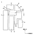
- FIG. 1 is a diagram illustrating a state where a shielding member 45 of an air guide structure 4 according to an embodiment is attached to a vehicle.
- FIG. 2 is a diagram illustrating a state in which the shielding member 45 of the air guide structure 4 according to the present embodiment has been removed from the vehicle.
- FIG. 3 is a sectional view taken along line XX of FIG.
- FIG. 4 is a sectional view taken along line YY of FIG.
- the vehicle has a side frame 1, an engine 2, a fan 3, and an air guide structure 4.
- the side frame 1 is a member extending in the front-rear direction of the vehicle. Two side frames 1 are provided in parallel.
- the engine 2 generates power for driving the vehicle.
- the engine 2 is, for example, a gasoline engine or a diesel engine.
- the engine 2 supplies fuel (for example, gasoline or light oil) and air to burn and generate power and generate exhaust gas.
- the engine 2 is provided behind the fan 3 in the front-rear direction of the vehicle.
- the fan 3 is a blower for flowing air.
- the fan 3 is provided in front of the engine 2. Specifically, the fan 3 is provided behind the radiator 41 in the front-rear direction of the vehicle and in front of the engine 2.
- the fan 3 is connected to the engine 2 via a shaft, and has a structure in which the fan 3 is rotatably driven by receiving power from the engine 2, but may be an electric fan.
- the fan 3 allows air to flow from the front to the rear in the front-rear direction of the vehicle.
- the air guide structure 4 reduces the amount of heated air flowing forward of the radiator 41 as described later.
- the air guide structure 4 includes a radiator 41, a plurality of members (for example, a frame 42, an intercooler 43, and a bumper beam 44), and a shielding member 45.
- the radiator 41 cools the heat transfer medium that cools the engine 2.
- the heat transfer medium is cooling water for cooling the engine 2.
- the heat transfer medium is circulating between the radiator 41 and the engine 2.
- the radiator 41 cools the heat transfer medium heated by flowing through the engine 2.
- the radiator 41 is provided in front of the engine 2.
- the radiator 41 has an air inlet through which cooling air (for example, traveling wind or air flowing from the fan 3) flows into a front surface of the vehicle in the front-rear direction, and causes the cooling air to flow out to the rear surface of the radiator 41. It has an air outlet.
- the radiator 41 is heated by exchanging heat between air flowing in from the front in the front-rear direction of the vehicle (for example, traveling wind or air flowing by the fan 3) and a heated heat transfer medium flowing out of the engine 2. Cool the heat transfer medium.
- the heat transfer medium cooled by the radiator 41 flows into the engine 2.
- the temperature of the air flowing out of the radiator 41 is higher than that of the air flowing into the radiator 41 by removing heat of the heat transfer medium flowing out of the engine 2 in the radiator 41.
- a plurality of members (for example, the frame 42, the intercooler 43, and the bumper beam 44) are at least partially provided in front of the radiator 41. Further, the plurality of members form a first gap S1 and a second gap S2.
- the first gap S1 is a gap formed between a plurality of members in the height direction of the vehicle.
- the plurality of members include a plurality of first members (for example, the frame 42 and the intercooler 43) and a second member (for example, the bumper beam 44).
- the plurality of first members are members that are at least partially provided in front of the radiator 41 and that form the first gap S1 in the height direction of the vehicle. Specifically, the first gap S1 is formed, for example, by the frame 42 and the intercooler 43.
- the second member is provided in front of a member provided at the lowest position in the height direction of the vehicle among the plurality of first members, and is located between the first member and a member provided at the lowest position.
- This is a member forming the second gap S2.
- the second gap S2 is formed by, for example, the intercooler 43 and the bumper beam 44.
- each of the plurality of members for example, the frame 42, the intercooler 43, and the bumper beam 44
- the frame 42 is, for example, a radiator support frame.
- the frame 42 extends in the vehicle width direction of the vehicle. At least a part of the frame 42 is provided in front of the radiator 41, and fixes the radiator 41 to the vehicle.
- the frame 42 is provided near the upper end of the radiator 41 in the vehicle height direction.
- the intercooler 43 is a device for cooling air whose temperature has been increased by compression with a supercharger (for example, a turbocharger).
- the supercharger is a device that uses the exhaust gas of the engine 2 to increase the pressure, that is, the density of the air supplied to the engine 2.
- the intercooler 43 is provided in front of the radiator 41 and below the frame 42.
- the upper end of the intercooler 43 is located below the upper end of the radiator 41 in the vehicle height direction.
- the intercooler 43 has an air inlet through which cooling air (for example, traveling wind or air flowing by the fan 3) flows into a front surface of the vehicle in the front-rear direction, and supplies the cooling air to a rear surface of the intercooler 43. It has an outflow air outlet.
- the intercooler 43 exchanges heat between air flowing in from the front in the front-rear direction of the vehicle (for example, traveling wind or air flowing by the fan 3) and air having a higher temperature flowing from the supercharger, thereby performing heat exchange. Cools the heated air that flows from the feeder.
- the air flowing out of the intercooler 43 deprives the heat of the air flowing from the supercharger in the intercooler 43, so that the temperature rises as compared with the air flowing into the intercooler 43.
- the bumper beam 44 is a member that absorbs a shock to the vehicle.
- the bumper beam 44 is, for example, a front bumper beam provided in front of the vehicle, and is provided in front of the intercooler 43.
- the bumper beam 44 extends in the vehicle width direction.
- the upper end of the bumper beam 44 is located below the upper end of the intercooler 43 in the vehicle height direction.
- the first gap S1 is formed by the lower surface of the frame 42 and the upper surface of the intercooler 43.
- the second gap S2 is formed by the front surface of the intercooler 43 and the rear surface of the bumper beam 44.
- the space formed in front and side of the radiator 41 has a complicated shape. .
- the air flowing from the front to the rear in the front-rear direction of the vehicle flows through the intercooler 43, the radiator 41, and the fan 3 and collides with the engine 2.
- the air is heated by heat exchange between the intercooler 43 and the radiator 41 as described above. That is, the temperature of the air flowing through the intercooler 43, the radiator 41, and the fan 3 is higher behind the fan 3 than at the front of the intercooler 43.
- the shielding member 45 is a member for suppressing the heated air flowing forward from flowing from the front and side of the radiator 41 toward the vicinity of the front surface of the radiator 41.
- the shielding member 45 is provided in front of and on the side of the radiator 41.
- the shielding member 45 is provided in front of the first gap S1. When the shielding member 45 is attached to the vehicle, the shielding member 45 extends in the height direction and the front-back direction of the vehicle. The shielding member 45 causes the air heated by the engine 2 to flow forward in the front-rear direction of the vehicle.
- the air guide structure 4 since the air guide structure 4 has the shielding member 45, it is possible to suppress the flow of heated air into the radiator 41, so that the cooling performance of the radiator 41 can be improved. That is, the air guide structure 4 can cool the heat transfer medium flowing through the radiator 41 more than when the shielding member 45 is not provided.
- the shielding member 45 has a guide main body 451, a shielding part 452, a guide mounting part 453, and a hinge part 454.
- the guide body 451 reduces the amount of air heated by the engine 2 flowing in front of the radiator 41.
- the guide body 451 is provided above a second gap S2 formed between a plurality of members. Specifically, the guide main body 451 is provided in front of the frame 42 and the intercooler 43 and above the bumper beam 44. When the shielding member 45 is attached to the vehicle, the guide main body 451 extends in the height direction and the front-back direction of the vehicle.
- the shield 452 reduces the amount of air heated by the engine 2 flowing forward of the radiator 41.
- the shielding part 452 is displaceable with respect to the guide body part 451, and shields at least a part of the first gap S1.
- the shielding part 452 is provided rotatably with respect to the guide main body part 451, and shields at least a part of the first gap S1.
- the rotation axis extends, for example, in the height direction of the vehicle.
- the shielding portion 452 extends in the height direction of the vehicle and in the front-back direction.
- the shielding portion 452 causes the air heated by the engine 2 to flow from the outside in the vehicle width direction to the inside in the first gap S1, that is, between the lower surface of the frame 42 and the upper surface of the intercooler 43. , The amount flowing forward of the radiator 41 is reduced.
- the guide mounting portion 453 is a member for fixing the shielding member 45 to the vehicle.
- the guide mounting portion 453 extends downward from the lower end of the guide main body 451 and is inserted into the second gap S2. Since the guide mounting portion 453 is inserted into the second gap S2, the air heated by the engine 2 allows the air heated by the engine 2 to pass through the second gap S2, that is, between the front surface of the intercooler 43 and the rear surface of the bumper beam 44. It is also possible to reduce the amount that flows from the outside to the inside in the vehicle width direction and flows forward of the radiator 41 and the intercooler 43. When the shielding member 45 is mounted on the vehicle, the guide mounting portion 453 extends in the height direction and the front-rear direction of the vehicle.
- the hinge 454 is a member that rotatably supports the shield 452 with respect to the guide body 451.
- the hinge 454 has, for example, one end fixed to an inner surface of the guide body 451 in the vehicle width direction of the vehicle, and the other end fixed to an end of the shielding part 452 on the guide body 451 side.
- the guide main body 451 has a fixing part 455.
- the fixing portion 455 is a member that protrudes inward from an inner surface of the guide body 451 in the vehicle width direction of the vehicle.
- the fixing portion 455 is, for example, a clip.
- the shielding portion 452 has a hole 456.
- the hole 456 is a hole into which the fixing portion 455 is inserted.
- the shielding part 452 is fixed by the fixing part 455 being inserted into the hole 456.
- the shielding portion 452 is substantially parallel to the guide main body 451.
- the shielding portion 452 of the shielding member 45 is substantially orthogonal to the guide body 451 of the shielding member 45, the assembly worker can move the shielding member 45 forward of the frame 42 and the intercooler 43.
- the area behind the bumper beam 44 can be easily moved up and down without, for example, the shielding portion 452 colliding with the frame 42.
- the assembly worker inserts the guide mounting portion 453 of the shielding member 45 into the second gap S2, attaches the shielding member 45 to the vehicle, and then becomes substantially parallel to the guide body 451 of the shielding member 45.
- the shielding part 452 of the shielding member 45 is moved. That is, the assembler moves the end of the shield 452 opposite to the end on the guide main body 451 side from the inside to the outside in the vehicle width direction of the vehicle, so that the guide main body 451 is The shielding part 452 of the shielding member 45 is moved so as to be parallel.
- the shielding portion 452 is fixed in a state substantially parallel to the guide main portion 451.
- the shielding part 452 shields at least a part of the first gap S1.
- the assembling worker can easily attach the shielding member 45 to the vehicle.
- at least a part of the mounting operation of the shielding member 45 may be performed by a mechanism controlled by a computer instead of the assembly operator.
- the air guide structure 4 includes a radiator 41 provided in front of the engine 2 of the vehicle and a plurality of members at least partially provided in front of the radiator 41 in a height direction of the vehicle. , A plurality of members forming a first gap S1 between the plurality of members, and a shielding member 45 provided in front of the first gap S1.
- the shielding member 45 is displaceable with respect to the guide main body 451 provided above the second gap S2 formed between the plurality of members, and the first gap S1.
- a shielding portion 452 that shields at least a part of.
- the air guide structure 4 according to the present embodiment is displaceable with respect to the guide body 451 provided above the second gap S2 formed between the plurality of members, and the guide body 451. And a shielding portion 452 that shields at least a part of the first gap S1. Therefore, in the air guide structure 4, by moving the shielding part 452 with respect to the guide main body part 451, the shielding member 45 can be moved from above with respect to the second gap S2, and the first gap can be moved. At least a part of the gap S1 can be shielded. As a result, the air guide structure 4 according to the present embodiment can improve the sealing performance while maintaining the assembling workability.
- the plurality of members are the frame 42, the intercooler 43, and the bumper beam 44
- the first gap S1 is formed by the frame 42 and the intercooler 43
- the second gap S2 is
- the plurality of members may be provided as long as they are provided in front of and near the side of the radiator 41 and form the first gap S1 and the second gap S2.
- the present disclosure has been described using the embodiment, but the technical scope of the present disclosure is not limited to the range described in the above embodiment, and various modifications and changes can be made within the scope of the gist. is there.
- the specific embodiment of the dispersion or integration of the apparatus is not limited to the above-described embodiment, and all or a part of the apparatus may be functionally or physically dispersed or integrated in an arbitrary unit. Can be.
- a new embodiment that is generated by an arbitrary combination of a plurality of embodiments is also included in the embodiments of the present disclosure. The effect of the new embodiment caused by the combination has the effect of the original embodiment.
- the air guide structure of the present disclosure is useful in that the sealability is improved while maintaining the workability of assembly.
Landscapes
- Engineering & Computer Science (AREA)
- Chemical & Material Sciences (AREA)
- Combustion & Propulsion (AREA)
- Mechanical Engineering (AREA)
- General Engineering & Computer Science (AREA)
- Physics & Mathematics (AREA)
- Thermal Sciences (AREA)
- Transportation (AREA)
- Cooling, Air Intake And Gas Exhaust, And Fuel Tank Arrangements In Propulsion Units (AREA)
- Body Structure For Vehicles (AREA)
Abstract
エアガイド構造は、車両のエンジンの前方に設けられているラジエータと、少なくとも一部がラジエータの前方に設けられた複数の部材であって、車両の高さ方向において複数の部材の間に第1の隙間を形成している複数の部材と、第1の隙間の前方に設けられた遮蔽部材とを備える。遮蔽部材は、複数の部材の間に形成された第2の隙間の上方に設けられたガイド本体部と、ガイド本体部に対して変位可能であり、第1の隙間の少なくとも一部を遮蔽する遮蔽部とを有する。
Description
本開示は、車両のエアガイド構造に関する。
車両にはエアガイド構造が設けられている。特許文献1には、ラジエータに走行風を導くための導風板を備える車両が開示されている。
車両の前後方向における前方から後方に向かって、ラジエータ、ファン、及びエンジンが設けられた構造を有する車両がある。この構造を有する車両では、ラジエータを前方から後方に向かって通過して、エンジン冷却水と熱交換することで加熱された空気が、ラジエータの後方に設けられているエンジンに衝突して、前方に向かって流れる場合がある。この場合、前方に向かって流れる加熱された空気が、ラジエータの前方かつ側方から、ラジエータの前方付近に流れ込み、ラジエータに流入することで、ラジエータの冷却性能が低下してしまうことがある。
この場合、ラジエータの前方かつ側方付近にシール部材を設けることで、加熱された空気がラジエータの前面付近に流れるのを抑制することが考えられる。しかし、ラジエータの前方かつ側方付近に、車両を構成する複数の部材が設けられている場合、シール部材によるシール性を向上させるためには、シール部材の組み付け作業性が悪化してしまうという問題が生じていた。
本開示の目的は、組み付け作業性を維持しつつ、シール性を向上させるエアガイド構造を提供することである。
本開示のエアガイド構造は、車両のエンジンの前方に設けられているラジエータと、少なくとも一部が前記ラジエータの前方に設けられた複数の部材であって、前記車両の高さ方向において前記複数の部材の間に第1の隙間を形成している前記複数の部材と、前記第1の隙間の前方に設けられた遮蔽部材と、を備え、前記遮蔽部材は、前記複数の部材の間に形成された第2の隙間の上方に設けられたガイド本体部と、前記ガイド本体部に対して変位可能であり、前記第1の隙間の少なくとも一部を遮蔽する遮蔽部と、を有する。
また、前記遮蔽部材は、前記エンジンにより加熱された空気を前記車両の前後方向における前方に流してもよい。また、前記遮蔽部材は、前記ガイド本体部の下端から下方に向かって延伸しており、かつ前記第2の隙間に挿入されているガイド取付部をさらに有し、前記遮蔽部は、前記ガイド本体部に対して回転可能に設けられており、かつ前記第1の隙間の少なくとも一部を遮蔽してもよい。
また、前記遮蔽部材は、前記ガイド本体部に対して前記遮蔽部を回転可能に支持するヒンジ部をさらに有し、前記ガイド本体部は、前記ガイド本体部の前記車両の車幅方向における内側の面から内側に向かって突出している固定部を有し、前記遮蔽部は、前記固定部が挿入される孔を有し、前記遮蔽部材が、前記車両に取り付けられた状態では、前記遮蔽部は、前記固定部が前記孔に挿入されていることで固定されていてもよい。
また、前記複数の部材は、少なくとも一部が前記ラジエータの前方に設けられており、かつ前記車両の高さ方向において前記第1の隙間を形成している複数の第1の部材と、前記複数の第1の部材のうちの前記車両の高さ方向における最下方に設けられている部材の前方に設けられており、かつ前記最下方に設けられている部材との間に前記第2の隙間を形成している第2の部材と、を有していてもよい。
また、前記複数の第1の部材は、少なくとも一部が前記ラジエータの前方に設けられており、かつ前記ラジエータを前記車両に固定するフレームと、前記ラジエータの前方に設けられており、かつ前記フレームよりも下方に設けられているインタークーラと、を含み、前記第2の部材は、前記インタークーラの前方に設けられているバンパービームを含み、前記第1の隙間は、前記フレームと前記インタークーラとで形成されており、前記第2の隙間は、前記インタークーラと前記バンパービームとで形成されていてもよい。
本開示のエアガイド構造によれば、組み付け作業性を維持しつつ、シール性を向上できる。
[エアガイド構造4の周辺構成]
図1は、一実施形態に係るエアガイド構造4の遮蔽部材45が車両に取り付けられている状態を示す図である。図2は、本実施形態に係るエアガイド構造4の遮蔽部材45が車両から取り外されている状態を示す図である。図3は、図1のX-X線断面図である。図4は、図3のY-Y線断面図である。
図1は、一実施形態に係るエアガイド構造4の遮蔽部材45が車両に取り付けられている状態を示す図である。図2は、本実施形態に係るエアガイド構造4の遮蔽部材45が車両から取り外されている状態を示す図である。図3は、図1のX-X線断面図である。図4は、図3のY-Y線断面図である。
車両は、サイドフレーム1、エンジン2、ファン3、及びエアガイド構造4を有する。サイドフレーム1は、車両の前後方向において延伸している部材である。2本のサイドフレーム1が平行に設けられている。
エンジン2は、車両を駆動するための動力を発生する。エンジン2は、例えばガソリンエンジン又はディーゼルエンジンである。エンジン2は、燃料(例えば、ガソリン又は軽油)及び空気を供給して燃焼させることで動力を発生すると共に排気ガスを生じる。エンジン2は、車両の前後方向において、ファン3の後方に設けられている。
ファン3は、空気を流す送風機である。ファン3は、エンジン2の前方に設けられている。具体的には、ファン3は、車両の前後方向におけるラジエータ41の後方、かつエンジン2の前方に設けられている。ファン3は、エンジン2に軸を介して連結されており、エンジン2から動力を受けて回転駆動される構造であるが、電動ファンであってもよい。ファン3は、車両の前後方向における前方から後方に向かって空気を流す。
[エアガイド構造4]
エアガイド構造4は、後述するように、加熱された空気がラジエータ41の前方に流れる量を低減させる。エアガイド構造4は、ラジエータ41、複数の部材(例えば、フレーム42、インタークーラ43、及びバンパービーム44)、及び遮蔽部材45を有する。
エアガイド構造4は、後述するように、加熱された空気がラジエータ41の前方に流れる量を低減させる。エアガイド構造4は、ラジエータ41、複数の部材(例えば、フレーム42、インタークーラ43、及びバンパービーム44)、及び遮蔽部材45を有する。
ラジエータ41は、エンジン2を冷却する熱搬送媒体を冷却する。熱搬送媒体は、エンジン2を冷却する冷却水である。熱搬送媒体は、ラジエータ41とエンジン2との間で循環している。ラジエータ41は、エンジン2を流れることで加熱された熱搬送媒体を冷却する。
ラジエータ41は、エンジン2の前方に設けられている。ラジエータ41は、車両の前後方向における前面に冷却用の空気(例えば、走行風又はファン3よって流れる空気)を流入させる空気流入口を有し、ラジエータ41の後面に当該冷却用の空気を流出させる空気流出口を有する。ラジエータ41は、車両の前後方向における前方から流入した空気(例えば、走行風又はファン3によって流れる空気)と、エンジン2から流出した加熱された熱搬送媒体とを熱交換することで、加熱された熱搬送媒体を冷却する。ラジエータ41で冷却された熱搬送媒体は、エンジン2に流入する。
また、ラジエータ41から流出する空気は、ラジエータ41においてエンジン2から流出した熱搬送媒体の熱を奪うことで、ラジエータ41に流入する空気に比べて、温度が上昇する。
複数の部材(例えば、フレーム42、インタークーラ43、及びバンパービーム44)は、少なくとも一部がラジエータ41の前方に設けられている。また、複数の部材は、第1の隙間S1及び第2の隙間S2を形成している。第1の隙間S1は、車両の高さ方向において複数の部材の間に形成されている隙間である。
複数の部材は、複数の第1の部材(例えば、フレーム42、及びインタークーラ43)と、第2の部材(例えば、バンパービーム44)とを有する。複数の第1の部材は、少なくとも一部がラジエータ41の前方に設けられており、かつ車両の高さ方向において第1の隙間S1を形成している部材である。具体的には、第1の隙間S1は、例えば、フレーム42とインタークーラ43とで形成されている。
第2の部材は、複数の第1の部材のうちの車両の高さ方向における最下方に設けられている部材の前方に設けられており、かつ最下方に設けられている部材との間に第2の隙間S2を形成している部材である。具体的には、第2の隙間S2は、例えば、インタークーラ43とバンパービーム44とで形成されている。以下に、複数の部材(例えば、フレーム42、インタークーラ43、及びバンパービーム44)、それぞれについて説明する。
フレーム42は、例えば、ラジエータサポートフレームである。フレーム42は、車両の車幅方向において延伸している。フレーム42は、少なくとも一部がラジエータ41の前方に設けられており、かつラジエータ41を車両に固定する。フレーム42は、ラジエータ41の車両の高さ方向における上端付近に設けられている。
インタークーラ43は、過給機(例えばターボチャージャ)で圧縮することにより温度が上昇した空気を冷却するための装置である。過給機は、エンジン2の排気ガスを利用してエンジン2に供給する空気の圧力、すなわち密度を高める装置である。
インタークーラ43は、ラジエータ41の前方に設けられており、かつフレーム42よりも下方に設けられている。インタークーラ43の上端は、ラジエータ41の上端よりも車両の高さ方向において下方に位置する。
インタークーラ43は、車両の前後方向における前面に冷却用の空気(例えば、走行風又はファン3によって流れる空気)を流入させる空気流入口を有し、インタークーラ43の後面に当該冷却用の空気を流出させる空気流出口を有する。インタークーラ43は、車両の前後方向における前方から流入した空気(例えば、走行風又はファン3によって流れる空気)と、過給機から流れてきた温度が上昇した空気とを熱交換することで、過給機から流れてきた温度が上昇した空気を冷却する。インタークーラ43から流出する空気は、インタークーラ43において過給機から流れてきた空気の熱を奪うことで、インタークーラ43に流入する空気に比べて、温度が上昇する。
バンパービーム44は、車両に対する衝撃を吸収する部材である。具体的には、バンパービーム44は、例えば車両の前方に設けられているフロントバンパービームであり、インタークーラ43の前方に設けられている。バンパービーム44は、車両の車幅方向において延伸している。バンパービーム44の上端は、インタークーラ43の上端よりも車両の高さ方向において下方に位置する。
前述したように、第1の隙間S1は、フレーム42の下面とインタークーラ43の上面とで形成されている。また、第2の隙間S2は、インタークーラ43の前面とバンパービーム44の後面とで形成されている。
車両は、このように複数の部材(例えば、フレーム42、インタークーラ43、及びバンパービーム44)を有することで、ラジエータ41の前方かつ側方に形成されている空間が複雑な形状になっている。
車両の前後方向における前方から後方に流れる空気(例えば、走行風又はファン3によって流れる空気)は、インタークーラ43、ラジエータ41、及びファン3を流れてエンジン2に衝突する。当該空気は、前述したようにインタークーラ43及びラジエータ41でそれぞれ熱交換することで加熱される。すなわち、インタークーラ43、ラジエータ41、及びファン3を流れる空気は、ファン3の後方では、インタークーラ43の前方よりも温度が高い。
ファン3から後方に向かって流出した、インタークーラ43及びラジエータ41で加熱された空気は、エンジン2の前面に衝突することで、当該加熱された空気の一部はファン3及びラジエータ41の側方を、車両の前後方向における前方に向かって流れる(以下、インタークーラ43及びラジエータ41で加熱された空気を「前方に向かって流れる加熱された空気」という。)。
遮蔽部材45は、前方に向かって流れる加熱された空気が、ラジエータ41の前方かつ側方から、ラジエータ41の前面付近に向かって流れることを抑制する部材である。遮蔽部材45は、ラジエータ41の前方かつ側方に設けられている。遮蔽部材45は、第1の隙間S1の前方に設けられている。遮蔽部材45が車両に取り付けられた状態では、遮蔽部材45は、車両の高さ方向及び前後方向において延在している。遮蔽部材45は、エンジン2により加熱された空気を車両の前後方向における前方に流す。
この結果、エアガイド構造4は、遮蔽部材45を有することで、ラジエータ41に加熱された空気を流入させることを抑制することができるので、ラジエータ41の冷却性能を向上させることができる。すなわち、エアガイド構造4は、遮蔽部材45が設けられていない場合に比べて、ラジエータ41を流れる熱搬送媒体をより冷却することができる。
[遮蔽部材45の詳細構成]
図1に示すように、遮蔽部材45は、ガイド本体部451、遮蔽部452、ガイド取付部453、及びヒンジ部454を有する。ガイド本体部451は、エンジン2により加熱された空気がラジエータ41の前方に流れる量を低減させる。
図1に示すように、遮蔽部材45は、ガイド本体部451、遮蔽部452、ガイド取付部453、及びヒンジ部454を有する。ガイド本体部451は、エンジン2により加熱された空気がラジエータ41の前方に流れる量を低減させる。
ガイド本体部451は、複数の部材の間に形成された第2の隙間S2の上方に設けられている。具体的には、ガイド本体部451は、フレーム42及びインタークーラ43の前方、かつバンパービーム44の上方に設けられている。遮蔽部材45が車両に取り付けられた状態では、ガイド本体部451は、車両の高さ方向及び前後方向において延在している。
遮蔽部452は、エンジン2により加熱された空気がラジエータ41の前方に流れる量を低減させる。遮蔽部452は、ガイド本体部451に対して変位可能であり、第1の隙間S1の少なくとも一部を遮蔽する。具体的には、遮蔽部452は、ガイド本体部451に対して回転可能に設けられており、かつ第1の隙間S1の少なくとも一部を遮蔽する。回転軸は、例えば車両の高さ方向において延伸している。遮蔽部材45が車両に取り付けられた状態では、遮蔽部452は、車両の高さ方向及び前後方向において延在している。
遮蔽部452は、エンジン2により加熱された空気が、第1の隙間S1、すなわち、フレーム42の下面とインタークーラ43の上面との間を車両の車幅方向における外側から内側に向かって流れて、ラジエータ41の前方に流れる量を低減させる。
ガイド取付部453は、遮蔽部材45を車両に対して固定するための部材である。ガイド取付部453は、ガイド本体部451の下端から下方に向かって延伸しており、かつ第2の隙間S2に挿入されている。ガイド取付部453は、第2の隙間S2に挿入されていることで、エンジン2により加熱された空気が第2の隙間S2、すなわち、インタークーラ43の前面とバンパービーム44の後面との間を車両の車幅方向における外側から内側に向かって流れて、ラジエータ41及びインタークーラ43の前方に流れる量を低減させることもできる。遮蔽部材45が車両に取り付けられた状態では、ガイド取付部453は、車両の高さ方向及び前後方向において延在している。
ヒンジ部454は、ガイド本体部451に対して遮蔽部452を回転可能に支持する部材である。ヒンジ部454は、例えば一端がガイド本体部451の車両の車幅方向における内側の面に固定されており、他端が遮蔽部452のガイド本体部451側の端部に固定されている。
また、ガイド本体部451は、固定部455を有する。固定部455は、ガイド本体部451の車両の車幅方向における内側の面から内側に向かって突出している部材である。固定部455は、例えばクリップである。
また、遮蔽部452は、孔456を有する。孔456は、固定部455が挿入される孔である。遮蔽部材45が、車両に取り付けられた状態では、遮蔽部452は、固定部455が孔456に挿入されていることで固定されている。このとき、遮蔽部452は、ガイド本体部451に対して略平行である。
[遮蔽部材45の取付方法]
まず、エアガイド構造4を組み立てる組立作業者は、車両の高さ方向における上方から下方に向かって遮蔽部材45を移動させることで、遮蔽部材45のガイド取付部453を第2の隙間S2に挿入する。このとき、ガイド本体部451の固定部455は、遮蔽部452の孔456に挿入されておらず、遮蔽部材45の遮蔽部452は、例えば、遮蔽部材45のガイド本体部451に対して略直交した状態である。すなわち、遮蔽部材45の遮蔽部452は、例えば車両の車幅方向及び高さ方向において延在している。
まず、エアガイド構造4を組み立てる組立作業者は、車両の高さ方向における上方から下方に向かって遮蔽部材45を移動させることで、遮蔽部材45のガイド取付部453を第2の隙間S2に挿入する。このとき、ガイド本体部451の固定部455は、遮蔽部452の孔456に挿入されておらず、遮蔽部材45の遮蔽部452は、例えば、遮蔽部材45のガイド本体部451に対して略直交した状態である。すなわち、遮蔽部材45の遮蔽部452は、例えば車両の車幅方向及び高さ方向において延在している。
このように、遮蔽部材45の遮蔽部452が、遮蔽部材45のガイド本体部451に対して略直交した状態にあることで、組立作業者は、遮蔽部材45をフレーム42及びインタークーラ43の前方、かつバンパービーム44の後方の領域を、例えば遮蔽部452がフレーム42に衝突することなく容易に上下方向に移動させることができる。
そして、組立作業者は、遮蔽部材45のガイド取付部453を第2の隙間S2に挿入して、遮蔽部材45を車両に取り付けた後に、遮蔽部材45のガイド本体部451と略平行になるように遮蔽部材45の遮蔽部452を移動させる。すなわち、組立作業者は、例えば遮蔽部452のガイド本体部451側の端部とは反対側の端部を車両の車幅方向における内側から外側に向かって移動させることで、ガイド本体部451と平行になるように遮蔽部材45の遮蔽部452を移動させる。このとき、遮蔽部材45の遮蔽部452の孔456に遮蔽部材45のガイド本体部451の固定部455を挿入することで、遮蔽部452はガイド本体部451と略平行な状態で固定される。
この結果、遮蔽部452は、第1の隙間S1の少なくとも一部を遮蔽する。このようにして、組立作業者は、遮蔽部材45を容易に車両に取り付けることができる。なお、上記の遮蔽部材45の取付け作業の少なくとも一部を、組立作業者ではなく、コンピュータにより制御された機構が実行してもよい。
[本実施形態に係るエアガイド構造4による効果]
本実施形態に係るエアガイド構造4は、車両のエンジン2の前方に設けられているラジエータ41と、少なくとも一部がラジエータ41の前方に設けられた複数の部材であって、車両の高さ方向において複数の部材の間に第1の隙間S1を形成している複数の部材と、第1の隙間S1の前方に設けられた遮蔽部材45と、を備える。そして、遮蔽部材45は、複数の部材の間に形成された第2の隙間S2の上方に設けられたガイド本体部451と、ガイド本体部451に対して変位可能であり、第1の隙間S1の少なくとも一部を遮蔽する遮蔽部452と、を有する。
本実施形態に係るエアガイド構造4は、車両のエンジン2の前方に設けられているラジエータ41と、少なくとも一部がラジエータ41の前方に設けられた複数の部材であって、車両の高さ方向において複数の部材の間に第1の隙間S1を形成している複数の部材と、第1の隙間S1の前方に設けられた遮蔽部材45と、を備える。そして、遮蔽部材45は、複数の部材の間に形成された第2の隙間S2の上方に設けられたガイド本体部451と、ガイド本体部451に対して変位可能であり、第1の隙間S1の少なくとも一部を遮蔽する遮蔽部452と、を有する。
本実施形態に係るエアガイド構造4は、複数の部材の間に形成された第2の隙間S2の上方に設けられたガイド本体部451と、ガイド本体部451に対して変位可能であり、第1の隙間S1の少なくとも一部を遮蔽する遮蔽部452と、を有する遮蔽部材45を有する。よって、エアガイド構造4において、遮蔽部452をガイド本体部451に対して移動させることで、遮蔽部材45を第2の隙間S2に対して上方から移動させることが可能であり、かつ第1の隙間S1の少なくとも一部を遮蔽することができる。この結果、本実施形態に係るエアガイド構造4は、組み付け作業性を維持しつつ、シール性を向上させることができる。
[変形例]
上記実施形態では、複数の部材は、フレーム42、インタークーラ43、及びバンパービーム44であり、第1の隙間S1は、フレーム42とインタークーラ43とで形成されており、第2の隙間S2は、インタークーラ43とバンパービーム44とで形成されている例を示したが、これに限定されない。複数の部材は、ラジエータ41の前方かつ側方付近に設けられており、かつ第1の隙間S1及び第2の隙間S2を形成している部品であればよい。
上記実施形態では、複数の部材は、フレーム42、インタークーラ43、及びバンパービーム44であり、第1の隙間S1は、フレーム42とインタークーラ43とで形成されており、第2の隙間S2は、インタークーラ43とバンパービーム44とで形成されている例を示したが、これに限定されない。複数の部材は、ラジエータ41の前方かつ側方付近に設けられており、かつ第1の隙間S1及び第2の隙間S2を形成している部品であればよい。
以上、本開示を実施の形態を用いて説明したが、本開示の技術的範囲は上記実施の形態に記載の範囲には限定されず、その要旨の範囲内で種々の変形及び変更が可能である。例えば、装置の分散又は統合の具体的な実施の形態は、以上の実施の形態に限られず、その全部又は一部について、任意の単位で機能的又は物理的に分散又は統合して構成することができる。また、複数の実施の形態の任意の組み合わせによって生じる新たな実施の形態も、本開示の実施の形態に含まれる。組み合わせによって生じる新たな実施の形態の効果は、もとの実施の形態の効果を合わせ持つ。
本出願は、2018年9月13日付で出願された日本国特許出願(特願2018-171771)に基づくものであり、その内容はここに参照として取り込まれる。
本開示のエアガイド構造は、組み付け作業性を維持しつつシール性を向上するといった点において有用である。
1・・・サイドフレーム
2・・・エンジン
3・・・ファン
4・・・エアガイド構造
41・・・ラジエータ
42・・・フレーム
43・・・インタークーラ
44・・・バンパービーム
45・・・遮蔽部材
451・・・ガイド本体部
452・・・遮蔽部
453・・・ガイド取付部
454・・・ヒンジ部
455・・・固定部
456・・・孔
S1・・・第1の隙間
S2・・・第2の隙間
2・・・エンジン
3・・・ファン
4・・・エアガイド構造
41・・・ラジエータ
42・・・フレーム
43・・・インタークーラ
44・・・バンパービーム
45・・・遮蔽部材
451・・・ガイド本体部
452・・・遮蔽部
453・・・ガイド取付部
454・・・ヒンジ部
455・・・固定部
456・・・孔
S1・・・第1の隙間
S2・・・第2の隙間
Claims (6)
- 車両のエンジンの前方に設けられているラジエータと、
少なくとも一部が前記ラジエータの前方に設けられた複数の部材であって、前記車両の高さ方向において前記複数の部材の間に第1の隙間を形成している前記複数の部材と、
前記第1の隙間の前方に設けられた遮蔽部材と、
を備え、
前記遮蔽部材は、
前記複数の部材の間に形成された第2の隙間の上方に設けられたガイド本体部と、
前記ガイド本体部に対して変位可能であり、前記第1の隙間の少なくとも一部を遮蔽する遮蔽部と、
を有することを特徴とするエアガイド構造。 - 前記遮蔽部材は、前記エンジンにより加熱された空気を前記車両の前後方向における前方に流すことを特徴とする、
請求項1に記載のエアガイド構造。 - 前記遮蔽部材は、
前記ガイド本体部の下端から下方に向かって延伸しており、かつ前記第2の隙間に挿入されているガイド取付部をさらに有し、
前記遮蔽部は、前記ガイド本体部に対して回転可能に設けられており、かつ前記第1の隙間の少なくとも一部を遮蔽することを特徴とする、
請求項1又は2に記載のエアガイド構造。 - 前記遮蔽部材は、
前記ガイド本体部に対して前記遮蔽部を回転可能に支持するヒンジ部をさらに有し、
前記ガイド本体部は、前記ガイド本体部の前記車両の車幅方向における内側の面から内側に向かって突出している固定部を有し、
前記遮蔽部は、前記固定部が挿入される孔を有し、
前記遮蔽部材が、前記車両に取り付けられた状態では、前記遮蔽部は、前記固定部が前記孔に挿入されていることで固定されていることを特徴とする、
請求項1から3のいずれか一項に記載のエアガイド構造。 - 前記複数の部材は、
少なくとも一部が前記ラジエータの前方に設けられており、かつ前記車両の高さ方向において前記第1の隙間を形成している複数の第1の部材と、
前記複数の第1の部材のうちの前記車両の高さ方向における最下方に設けられている部材の前方に設けられており、かつ前記最下方に設けられている部材との間に前記第2の隙間を形成している第2の部材と、
を有することを特徴とする、
請求項1から4のいずれか一項に記載のエアガイド構造。 - 前記複数の第1の部材は、
少なくとも一部が前記ラジエータの前方に設けられており、かつ前記ラジエータを前記車両に固定するフレームと、
前記ラジエータの前方に設けられており、かつ前記フレームよりも下方に設けられているインタークーラと、
を含み、
前記第2の部材は、前記インタークーラの前方に設けられているバンパービームを含み、
前記第1の隙間は、前記フレームと前記インタークーラとで形成されており、
前記第2の隙間は、前記インタークーラと前記バンパービームとで形成されていることを特徴とする、
請求項5に記載のエアガイド構造。
Priority Applications (2)
| Application Number | Priority Date | Filing Date | Title |
|---|---|---|---|
| CN201980059971.4A CN112714709B (zh) | 2018-09-13 | 2019-09-09 | 空气引导结构 |
| PH12021550526A PH12021550526A1 (en) | 2018-09-13 | 2021-03-11 | Air guide structure |
Applications Claiming Priority (2)
| Application Number | Priority Date | Filing Date | Title |
|---|---|---|---|
| JP2018-171771 | 2018-09-13 | ||
| JP2018171771A JP2020040630A (ja) | 2018-09-13 | 2018-09-13 | エアガイド構造 |
Publications (1)
| Publication Number | Publication Date |
|---|---|
| WO2020054638A1 true WO2020054638A1 (ja) | 2020-03-19 |
Family
ID=69778070
Family Applications (1)
| Application Number | Title | Priority Date | Filing Date |
|---|---|---|---|
| PCT/JP2019/035292 Ceased WO2020054638A1 (ja) | 2018-09-13 | 2019-09-09 | エアガイド構造 |
Country Status (4)
| Country | Link |
|---|---|
| JP (1) | JP2020040630A (ja) |
| CN (1) | CN112714709B (ja) |
| PH (1) | PH12021550526A1 (ja) |
| WO (1) | WO2020054638A1 (ja) |
Citations (3)
| Publication number | Priority date | Publication date | Assignee | Title |
|---|---|---|---|---|
| JP2005096684A (ja) * | 2003-09-26 | 2005-04-14 | Toyota Motor Corp | 車体前部の導風構造 |
| JP2008068688A (ja) * | 2006-09-13 | 2008-03-27 | Calsonic Kansei Corp | 車両用エアガイド |
| JP2010149623A (ja) * | 2008-12-24 | 2010-07-08 | Daimler Ag | ラジエータ冷却風巻返し防止構造 |
Family Cites Families (4)
| Publication number | Priority date | Publication date | Assignee | Title |
|---|---|---|---|---|
| JP5620085B2 (ja) * | 2009-10-26 | 2014-11-05 | 富士重工業株式会社 | 可変ダクト装置 |
| JP2012081795A (ja) * | 2010-10-07 | 2012-04-26 | Kojima Press Industry Co Ltd | 自動車前部の導風構造 |
| FR2981887B1 (fr) * | 2011-11-02 | 2015-04-17 | Renault Sas | Guide d'air structurel et modulaire a fonction de face avant technique de moteur de vehicule automobile et vehicule ainsi equipe. |
| CN206287824U (zh) * | 2015-11-09 | 2017-06-30 | 爱信精机株式会社 | 车辆用散热装置 |
-
2018
- 2018-09-13 JP JP2018171771A patent/JP2020040630A/ja active Pending
-
2019
- 2019-09-09 WO PCT/JP2019/035292 patent/WO2020054638A1/ja not_active Ceased
- 2019-09-09 CN CN201980059971.4A patent/CN112714709B/zh active Active
-
2021
- 2021-03-11 PH PH12021550526A patent/PH12021550526A1/en unknown
Patent Citations (3)
| Publication number | Priority date | Publication date | Assignee | Title |
|---|---|---|---|---|
| JP2005096684A (ja) * | 2003-09-26 | 2005-04-14 | Toyota Motor Corp | 車体前部の導風構造 |
| JP2008068688A (ja) * | 2006-09-13 | 2008-03-27 | Calsonic Kansei Corp | 車両用エアガイド |
| JP2010149623A (ja) * | 2008-12-24 | 2010-07-08 | Daimler Ag | ラジエータ冷却風巻返し防止構造 |
Also Published As
| Publication number | Publication date |
|---|---|
| PH12021550526A1 (en) | 2022-02-21 |
| JP2020040630A (ja) | 2020-03-19 |
| CN112714709A (zh) | 2021-04-27 |
| CN112714709B (zh) | 2023-11-21 |
Similar Documents
| Publication | Publication Date | Title |
|---|---|---|
| US20130284530A1 (en) | Battery cooling system and method | |
| JP2018199445A (ja) | 車両用熱交換装置 | |
| JP5085205B2 (ja) | ラジエータシール構造 | |
| KR101693348B1 (ko) | 액티브 에어 플랩 | |
| JP2016199260A (ja) | ラジエータ装置を備えた自動車 | |
| KR101727182B1 (ko) | 차량용 캐리어 | |
| KR102067674B1 (ko) | 차량용 루프형 공조장치 | |
| KR20180047133A (ko) | 농작업차량에서의 이물질 유입 방지 장치 | |
| JP6504140B2 (ja) | 車両用冷却装置 | |
| KR101756178B1 (ko) | 차량용 캐리어 | |
| JP2020040630A (ja) | エアガイド構造 | |
| JP3047729B2 (ja) | エンジンマウント部材冷却構造 | |
| JP2011126434A (ja) | 車両用インタークーラの配管装置 | |
| JP2008302734A (ja) | ハイブリッド電気自動車のラジエータ構造 | |
| JP2015128923A (ja) | 車両用冷却装置 | |
| JP2019147527A (ja) | 車両前部構造 | |
| KR102050986B1 (ko) | 차량용 캐리어 | |
| KR20130008710A (ko) | 차량용 캐리어 | |
| WO2020054588A1 (ja) | ラジエータ構造 | |
| JP2018103801A (ja) | ラジエタファンシュラウド構造 | |
| KR20180093624A (ko) | 슈라우드의 공기 역순환 방지구조 | |
| KR101318105B1 (ko) | 차량용 캐리어 | |
| JP6428346B2 (ja) | エンジンの冷却装置 | |
| JP2018079830A (ja) | グリルシャッターの取り付け構造 | |
| JP6763291B2 (ja) | 車両前部構造 |
Legal Events
| Date | Code | Title | Description |
|---|---|---|---|
| 121 | Ep: the epo has been informed by wipo that ep was designated in this application |
Ref document number: 19859433 Country of ref document: EP Kind code of ref document: A1 |
|
| WWE | Wipo information: entry into national phase |
Ref document number: 2101001394 Country of ref document: TH |
|
| NENP | Non-entry into the national phase |
Ref country code: DE |
|
| 122 | Ep: pct application non-entry in european phase |
Ref document number: 19859433 Country of ref document: EP Kind code of ref document: A1 |