WO2020054616A1 - 電動作業機 - Google Patents
電動作業機 Download PDFInfo
- Publication number
- WO2020054616A1 WO2020054616A1 PCT/JP2019/035217 JP2019035217W WO2020054616A1 WO 2020054616 A1 WO2020054616 A1 WO 2020054616A1 JP 2019035217 W JP2019035217 W JP 2019035217W WO 2020054616 A1 WO2020054616 A1 WO 2020054616A1
- Authority
- WO
- WIPO (PCT)
- Prior art keywords
- motor
- working machine
- electric working
- control unit
- machine according
- Prior art date
- Legal status (The legal status is an assumption and is not a legal conclusion. Google has not performed a legal analysis and makes no representation as to the accuracy of the status listed.)
- Ceased
Links
Images






Classifications
-
- B—PERFORMING OPERATIONS; TRANSPORTING
- B24—GRINDING; POLISHING
- B24B—MACHINES, DEVICES, OR PROCESSES FOR GRINDING OR POLISHING; DRESSING OR CONDITIONING OF ABRADING SURFACES; FEEDING OF GRINDING, POLISHING, OR LAPPING AGENTS
- B24B23/00—Portable grinding machines, e.g. hand-guided; Accessories therefor
- B24B23/02—Portable grinding machines, e.g. hand-guided; Accessories therefor with rotating grinding tools; Accessories therefor
- B24B23/028—Angle tools
-
- B—PERFORMING OPERATIONS; TRANSPORTING
- B24—GRINDING; POLISHING
- B24B—MACHINES, DEVICES, OR PROCESSES FOR GRINDING OR POLISHING; DRESSING OR CONDITIONING OF ABRADING SURFACES; FEEDING OF GRINDING, POLISHING, OR LAPPING AGENTS
- B24B55/00—Safety devices for grinding or polishing machines; Accessories fitted to grinding or polishing machines for keeping tools or parts of the machine in good working condition
- B24B55/02—Equipment for cooling the grinding surfaces, e.g. devices for feeding coolant
-
- B—PERFORMING OPERATIONS; TRANSPORTING
- B25—HAND TOOLS; PORTABLE POWER-DRIVEN TOOLS; MANIPULATORS
- B25F—COMBINATION OR MULTI-PURPOSE TOOLS NOT OTHERWISE PROVIDED FOR; DETAILS OR COMPONENTS OF PORTABLE POWER-DRIVEN TOOLS NOT PARTICULARLY RELATED TO THE OPERATIONS PERFORMED AND NOT OTHERWISE PROVIDED FOR
- B25F5/00—Details or components of portable power-driven tools not particularly related to the operations performed and not otherwise provided for
-
- B—PERFORMING OPERATIONS; TRANSPORTING
- B25—HAND TOOLS; PORTABLE POWER-DRIVEN TOOLS; MANIPULATORS
- B25F—COMBINATION OR MULTI-PURPOSE TOOLS NOT OTHERWISE PROVIDED FOR; DETAILS OR COMPONENTS OF PORTABLE POWER-DRIVEN TOOLS NOT PARTICULARLY RELATED TO THE OPERATIONS PERFORMED AND NOT OTHERWISE PROVIDED FOR
- B25F5/00—Details or components of portable power-driven tools not particularly related to the operations performed and not otherwise provided for
- B25F5/001—Gearings, speed selectors, clutches or the like specially adapted for rotary tools
-
- B—PERFORMING OPERATIONS; TRANSPORTING
- B25—HAND TOOLS; PORTABLE POWER-DRIVEN TOOLS; MANIPULATORS
- B25F—COMBINATION OR MULTI-PURPOSE TOOLS NOT OTHERWISE PROVIDED FOR; DETAILS OR COMPONENTS OF PORTABLE POWER-DRIVEN TOOLS NOT PARTICULARLY RELATED TO THE OPERATIONS PERFORMED AND NOT OTHERWISE PROVIDED FOR
- B25F5/00—Details or components of portable power-driven tools not particularly related to the operations performed and not otherwise provided for
- B25F5/008—Cooling means
-
- B—PERFORMING OPERATIONS; TRANSPORTING
- B25—HAND TOOLS; PORTABLE POWER-DRIVEN TOOLS; MANIPULATORS
- B25F—COMBINATION OR MULTI-PURPOSE TOOLS NOT OTHERWISE PROVIDED FOR; DETAILS OR COMPONENTS OF PORTABLE POWER-DRIVEN TOOLS NOT PARTICULARLY RELATED TO THE OPERATIONS PERFORMED AND NOT OTHERWISE PROVIDED FOR
- B25F5/00—Details or components of portable power-driven tools not particularly related to the operations performed and not otherwise provided for
- B25F5/02—Construction of casings, bodies or handles
Definitions
- the present invention relates to an electric working machine having a motor and a control unit inside a motor housing.
- the electric element or a member that may be energized to the electric element comes into contact with a portion of the wiring such as a power line where the insulating coating is removed, thereby causing a problem.
- the wiring particularly, a portion where the insulating coating is removed
- the wiring is electrically connected to the control unit.
- the present invention has been made in view of such a situation, and an object of the present invention is to provide an electric working machine capable of suppressing contact between a control unit provided inside a motor housing and wiring.
- the electric working machine has a motor housing that houses a motor and a first control unit that controls the motor, and an electrical connection between the motor and the first control unit is located outside the motor housing. It is characterized by doing.
- the first control unit may include a switching element for energizing the motor.
- a holder may be provided on the electric connection portion side of the motor housing, a plurality of holder through holes may be provided in the holder, and the motor side wiring may be inserted into the holder through hole. Further, the control unit side wiring may be inserted into the holder through hole located at a position different from the position where the motor side wiring passes.
- a gear case may be connected to one side of the motor housing, and the electrical connection portion may be located on the other side of the motor housing. Further, a handle housing may be provided on the other side of the motor housing, and the electric connection portion may be located inside the handle housing.
- a fan that is rotated by the motor and has an intake port and an exhaust port for generating a flow of air that cools the motor by rotation of the fan,
- the air flowing from the intake port may flow into the motor housing through the holder through-hole.
- An electrical connection between the motor and the first control unit may have a connector, and a holder for holding the connector may be provided on the other side of the motor housing.
- the motor housing may have a cylindrical integral structure molded so as to be indivisible.
- the motor may be a brushless motor
- the first control unit may be an inverter circuit that controls power supply to the motor.
- the electric working machine which can suppress the contact with the wiring provided with the control part provided inside the motor housing can be provided.
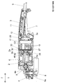
- FIG. 2 is a side sectional view of the electric working machine 1A according to Embodiment 1 of the present invention.
- FIG. 4 is an explanatory view of assembling a motor housing 2, a motor 6, a control unit 13, and a holder 17 of the electric working machine 1A.
- FIG. 4 is a rear view of the motor housing 2 incorporating the control unit 13 from the state of FIG. 3.
- FIG. 5 is a rear view of a state where the holder 17 is mounted on the motor housing 2 of FIG. 4.
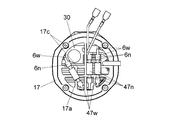
- FIG. 6 is a rear view of the state in which the wires 6 w and 47 w of FIG. FIG.
- FIG. 7 is a side sectional view of an electric working machine 1B according to a second embodiment of the present invention.
- FIG. 9 is a rear view of the motor housing 2 in which the bridge / inverter board 30 is incorporated from the state of FIG. 8.
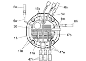
- FIG. 10 is a rear view of a state where the holder 17 is mounted on the motor housing 2 of FIG. 9.
- FIG. 11 is a rear view of a state where the connectors 6n and 47n of FIG. 10 are connected to each other and fitted into the recess 17b of the holder 17;
- the circuit diagram of the electric working machine 1B is a side sectional view of an electric working machine 1B according to a second embodiment of the present invention.
- FIG. 9 is a rear view of the motor housing 2 in which the bridge / inverter board 30
- FIG. 1 defines the up-down and front-back directions of the electric working machine 1A.
- the front-back direction is parallel to the extending direction of the rotating shaft 6a of the motor 6.
- the electric working machine 1A is a cordless type grinder that operates with power supplied from a battery pack 14 that is detachably mounted.
- the outer shell of the electric working machine 1A is formed by the motor housing 2, the handle housing (tail cover) 3, and the gear case 4.
- the handle housing 3 is attached (connected) to the rear end of the motor housing 2 via a holder (intermediate member) 17, and the gear case 4 is attached (connected) to the front end of the motor housing 2.
- the motor housing 2 and the handle housing 3 are, for example, resin moldings.
- the gear case 4 is made of a metal such as aluminum, for example.
- the gear case 4 supports a bearing (bearing) 6b that rotatably supports a front portion of the rotating shaft 6a.
- a battery pack 14 serving as a power supply source of the electric working machine 1A is detachably mounted.
- the handle housing 3 forms a handle of the electric working machine 1A.
- a trigger 7 is supported at the lower portion of the handle housing 3 so as to swing (rotate).
- the trigger 7 is an operation unit for the user to switch on and off the first switch 11 provided on the current path of the motor 6.
- the first switch 11 is preferably a mechanical contact switch, housed in the handle housing 3 and located above the trigger 7. When the user grips the trigger 7, the trigger 7 swings upward, and the first switch 11 is turned on. When the user releases the grip of the trigger 7, the trigger 7 swings downward, and the first switch 11 is turned off.
- the motor housing 2 has a cylindrical integrated structure such as a cylindrical shape extending in the front-rear direction and formed so as not to be divided, and has a front end and a rear end opening.
- the motor housing 2 houses the motor 6 and houses a control unit 13 at the rear of the motor 6.
- the control unit 13 includes an inverter circuit that controls power supply to the motor 6, a microcomputer (microcontroller) that controls the inverter circuit, and the like.
- the motor 6 is an inner rotor type brushless motor. Further, a fan 10 for cooling the motor 6 and the control unit 13 is provided at a front portion of the motor housing 2.
- the fan 10 is configured to rotate integrally with the rotating shaft 6a, and by rotating, generates cooling air from an intake port 3a provided on the left and right sides of the handle housing 3 to an exhaust port 4a provided on the gear case 4. . That is, the air that has flowed into the handle housing 3 from the intake port 3a by the rotation of the fan 10 flows into the motor housing 2 as cooling air, cools the control unit 13, cools the motor 6, and then cools the motor 6 through the exhaust port 4a. It is discharged outside.
- the gear case 4 accommodates a speed reduction mechanism 5 as a rotation transmission mechanism.
- the speed reduction mechanism 5 is a combination of a pair of bevel gears.
- the speed reduction mechanism 5 reduces the rotation of the motor 6 and converts the rotation by 90 degrees to transmit the rotation to the spindle 8.
- a grindstone 8a as a rotating tool is provided so as to be integrally rotatable. Since the mechanical configuration and operation from the rotation of the motor 6 to the rotation of the grindstone 8a are well known, further detailed description will be omitted.
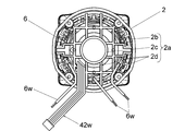
- FIG. 3 is a view of the motor housing 2 incorporating the motor 6 as viewed from the rear.
- the motor housing 2 has a bearing holding part 2a.
- the bearing holder 2a is located between the motor 6 and the controller 13 in the front-rear direction.
- the bearing holder 2a includes a rib 2b and a bearing housing 2c.
- the ribs 2b extend in a grid shape so as to pass over the inner peripheral surfaces of the motor housing 2.
- a plurality of through holes 2d are formed between the inner surface of the motor housing 2 and the bearing housing 2c by the ribs 2b forming a lattice shape. That is, the bearing holding portion 2a has a plurality of through holes 2d penetrating in the front-rear direction. In this embodiment, there are 20 through holes 2d.
- the bearing accommodating portion 2c is supported by the rib 2b, and accommodates and holds a bearing (bearing) 6c.
- the bearing 6c rotatably supports the rear part of the rotating shaft 6a of the motor 6.
- a plurality of through-holes 2d are provided, the wiring 6w and the signal line 42w pass through the through-holes 2d at different positions, so that contact between the wiring 6w and the signal line 42w can be suppressed.
- the position change of the plurality of wirings 6w can be restricted, and the contact between the wirings 6w can be suppressed.
- the movement of the wiring 6w and the signal line 42w is regulated by the ribs 2b around the through hole 2d. That is, since unnecessary movement of the wiring 6w and the signal line 42w is regulated by the bearing holding portion 2a, connection and assembly of the wiring are facilitated.
- the ribs 2b extending vertically and horizontally form a lattice shape.
- a plurality of ribs extending in one direction may form the through hole, for example, extending vertically.
- a plurality of ribs may form a fence.
- the plurality of wirings 6w are configured to all pass through the through holes 2d at different positions. However, if at least two wirings pass through the through holes 2d at different positions, the above-described effect can be obtained.
- a plurality of through holes for restricting the movement of the wiring are shared by a part of the bearing holding portion 2a, the plurality of through holes may be provided at another place.
- the rib 2b and the through-hole 2d correspond to the lattice portion of the present invention.
- FIG. 4 is a view of the motor housing 2 incorporating the control unit 13 from the state of FIG.
- the control unit 13 has a switching element, a microcomputer, and the like constituting an inverter circuit mounted on the rear surface of the control board.
- the wiring 47w is a wiring for supplying power to the motor 6 extending from the inverter circuit.
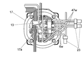
- FIG. 5 is a view of a state where the holder 17 is mounted on the motor housing 2 of FIG.
- the holder 17 has a cylindrical shape extending in the front-rear direction, and has open front and rear ends.
- the holder 17 has a grid-like rib 17a.
- the plurality of ribs 17a having a lattice shape like the rib 2b form a through hole 17c penetrating in the front-rear direction.
- the wiring 6w and the wiring 47w extend rearward through the gap between the ribs 17a (through hole 17c).
- the rib 17a having a lattice structure has an effect of restricting a change in the position of the wiring, similarly to the rib 2b.
- the wiring 6w and the wiring 47w are not connected, that is, the motor 6 and the control unit 13 are not electrically connected.
- the tips of the wirings 6w and 47w before the connection are in a state where the insulating material is removed.
- the connector 23 is included in an electrical connection between the wiring 6w and the wiring 47w, that is, an electrical connection between the motor 6 and the control unit 13, and has an insulating property that partially covers each of the wiring 6w and the wiring 47w. It is a member.
- the connector 23 covers the ends of the connected wires 6w and 47w and the vicinity thereof.
- the inside of the connector 23 is configured to be equal to or slightly smaller than the dimension obtained by combining the thicknesses of the wiring 6w and the wiring 47w, and the wiring 6w and the wiring 47w drop from the connector 23 due to frictional force or the like. You have been suppressed.
- the connector 23 is located outside (rearward) of the motor housing 2. Specifically, the connector 23 is located inside the handle housing 3. As shown in FIGS. 5 and 6, the wiring 6w and the wiring 47w are connected to each other through the through holes 17c at different positions.
- a final connection line between the motor 6 and the control unit 13 extends from the motor 6, extends to the outside of the motor housing 2, passes through the through-hole 17 c backward, and then passes over the rib 17 a to form another through-hole. It passes through the hole 17c, returns to the inside of the motor housing 2, and reaches the control unit 13. Therefore, at least a part of the connection line (wiring 6w or 47w) between the motor 5 and the control unit 13 located outside the motor housing 2 is restricted from moving into the motor housing 2 by the rib 17a.
- the through hole 17c corresponds to the holder through hole of the present invention. In the drawing, the leader lines are drawn only from some of the through holes 17c, but in the present embodiment, there are eight through holes 17c in total.
- the electrical connection (connector 23) between the wiring 6w of the motor 6 and the wiring 47w of the control unit 13 is arranged outside the motor housing 2, so that the electrical connection Can be prevented from contacting a part of the control unit 13.
- the switching elements and the microcomputer such as the microcomputer constituting the inverter circuit of the control unit 13 in the motor housing 2, other energized parts, the heat sink, etc. are exposed, the wiring 6w, 47w and the insulating coating removal parts of the wiring are provided on them. Can reduce the risk of causing a malfunction due to contact.
- the connector 23 since it is not necessary to provide a space for arranging the connector 23 in the motor housing 2, it is possible to suppress an increase in the size of the motor housing 2 and to prevent the flow of the cooling air passing through the motor housing 2 in the front-rear direction. Since there is a relatively large space in the handle housing 3 where the connector 23 is located, there is no problem even if the connector 23 is arranged. Further, since the connector 23 can be arranged inside the handle housing 3 having a sufficient space, a relatively inexpensive but large-sized connector member can be adopted, and an inexpensive electric working machine can be realized. Further, according to the present embodiment, when connecting the wiring 6w and the wiring 47w, since the motor 6 and the control unit 13 are both supported by the motor housing 2, they may move relative to each other. Is suppressed. Therefore, the connection work becomes very easy as compared with the case where only one is supported.
- FIG. 7 defines the up-down and front-back directions of the electric working machine 1B.
- the front-back direction is parallel to the extending direction of the rotating shaft 6a of the motor 6.
- the electric working machine 1 ⁇ / b> B is a cord-type grinder that operates with power supplied from an external AC power supply.
- the description will focus on the differences from the first embodiment.
- a power cord 9 for connecting to an external AC power supply 50 extends from the rear end of the handle housing 3.
- a controller 20 in which an auxiliary power supply / control board is accommodated is provided at a front portion in the handle housing 3.
- intake ports 3 a are provided as in the first embodiment.
- a second switch 12 is provided at a position on the front side of the trigger 7. The second switch 12 is, for example, an electronic switch (micro switch or the like) electrically connected to the calculation unit 21 in FIG. 12, and switches on and off in conjunction with the operation of the trigger 7.
- the second switch 12 is provided to quickly transmit the operation of the trigger 7 to the calculation unit 21, and sends a signal of a different level to the calculation unit 21 depending on its own on / off state.
- the trigger 7 swings upward, and the second switch 12 is turned on.
- the trigger 7 swings downward, and the second switch 12 is turned off.
- the motor housing 2 houses the motor 6 and also houses a bridge inverter board (drive board) 30 at the rear of the motor 6.
- a switching element Q (corresponding to the switching elements Q1 to Q6 in FIG. 12) constituting the inverter circuit 47 in FIG. 12, a heat sink (heat radiation member) 27 for cooling the switching element Q,
- An electrolytic capacitor C2 and the like are provided.
- a bearing holding portion 2a is provided between the motor 6 and the bridge / inverter board 30.
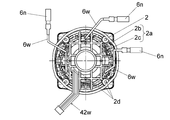
- FIG. 8 is a view of the motor housing 2 incorporating the motor 6 as viewed from the rear.
- the bearing accommodating portion 2c is supported by the rib 2b, and accommodates and holds a bearing (bearing) 28 in FIG.
- the bearing 28 rotatably supports the rear part of the rotation shaft of the motor 6.
- a connector 6n is provided at the end of the wiring 6w.
- the connector 6n is a connection component fixed to the tip of the wiring 6w, the metal part of which is covered with an insulating material, and can be engaged with a connector 47n described later.
- FIG. 9 is a view of the motor housing 2 incorporating the bridge / inverter board 30 from the state of FIG.
- the wiring 47w is a wiring extending from the inverter circuit provided on the bridge inverter board 30.
- a connector 47n is provided at the tip of the wiring 47w.
- the connector 47n is a connection component fixed to the tip of the wiring 47w, and has a metal portion covered with an insulating material, and can be engaged with the metal portion of the connector 6n.
- FIG. 10 is a view of a state where the holder 17 is mounted on the motor housing 2 of FIG. 9 as viewed from the rear.
- the wirings 6w and 47w extend rearward through gaps between the ribs 17a of the holder 17 (through holes 17c).
- FIG. 11 is a view showing a state where the connectors 6n and 47n of FIG. 10 are connected to each other and fitted into the concave portion 17b of the holder 17 as viewed from the rear.
- the wirings 6w and 47w are mechanically and electrically connected to each other.
- the insulating portions of the connectors 6n and 47n partially cover each of the wiring 6w and the wiring 47w.
- the interconnection between the connectors 6n and 47n is an electrical connection between the wirings 6w and 47w, that is, an electrical connection between the motor 6 and the bridge inverter board 30.
- the rib 17a has a plurality of recesses 17b.
- the connectors 6n and 47n and their interconnections are fitted and held in the recesses 17b.
- the handle housing 3 may have ribs for pressing the connectors 6n and 47n held in the concave portion 17b and their interconnecting portions from behind.
- FIG. 12 is a circuit diagram of the electric working machine 1B.
- the AC power supply 50 is an external AC power supply such as a commercial power supply.
- a filter circuit including a fuse Fin, a varistor Z1, a pattern fuse F1, a capacitor C1, a resistor R1, and a choke coil L1 is connected.
- the fuse Fin is for protection when the switching elements Q1 to Q6 are short-circuited.
- the varistor Z1 is for absorbing surge voltage.
- the pattern fuse F1 has a role of preventing a short circuit between the lines when the varistor Z1 operates.
- the capacitor C1 and the choke coil L1 are for removing noise between lines.
- the resistor R1 is for discharging the capacitor C1.
- the first switch 11 is provided between the output side of the aforementioned filter circuit and the input side of the diode bridge 15.
- the first switch 11 is a two-pole switch, which is connected between one output terminal of the filter circuit and one input terminal of the diode bridge 15, and between the other output terminal of the filter circuit and the other input terminal of the diode bridge 15. Between, both can be opened and closed.
- the diode bridge 15 as a rectifier circuit performs full-wave rectification on the output voltage of the above-described filter circuit input via the first switch 11, converts the output voltage to DC, and supplies the DC to the inverter circuit 47.
- the electrolytic capacitor C2 is for absorbing surge, and is provided between output terminals of the diode bridge 15.
- the resistor Rs is a detection resistor for detecting a current flowing through the motor 6, and is provided in a current path of the motor 6.
- the diode bridge 15, the electrolytic capacitor C2, the inverter circuit 47 as the first control unit, and the resistor Rs are provided on the bridge / inverter board 30 in FIG.
- the inverter circuit 47 includes switching elements Q1 to Q6 such as IGBTs and FETs connected in a three-phase bridge, performs a switching operation under the control of the arithmetic unit 21 as a second control unit, and operates the stator coils 6e (U, V and W).
- the calculation unit 21 detects the current of the motor 6 based on the voltage between both ends of the resistor Rs.
- the arithmetic unit 21 detects the rotation position (rotor rotation position) of the motor 6 based on the output voltages of the plurality of Hall elements (magnetic sensors) 42.
- the calculation unit 21 controls the driving and braking of the motor 6 according to the state (on / off) of the second switch 12 that is linked to the operation of the trigger 7.
- the arithmetic unit 21 performs switching control (for example, PWM control) of the switching elements Q1 to Q6, and controls driving of the motor 6.
- switching control for example, PWM control
- the calculation unit 21 performs control (brake control) for applying a braking force to the motor 6.
- the brake control is performed, for example, by turning on at least one of the lower arm side switching elements Q4 to Q6 continuously or intermittently while keeping the upper arm side switching elements Q1 to Q3 of the inverter circuit 47 off. This is control for generating power.
- Another diode bridge 16 as a rectifier circuit performs full-wave rectification on the output voltage of the above-described filter circuit, which is input without passing through the first switch 11, and converts the output voltage into DC.
- the electrolytic capacitor C3 is for absorbing surge, and is provided between output terminals of the diode bridge 16.
- An IPD circuit 22 is provided on the output side of the diode bridge 16.
- the IPD circuit 22 is a circuit configured by an IPD element, a capacitor, or the like, which is an intelligent power device (Intelligent Power Device).
- the IPD circuit 22 rectifies and smoothes a voltage rectified and smoothed by the diode bridge 16 and the surge absorbing electrolytic capacitor C3, for example.
- the IPD circuit 22 is an integrated circuit and has the advantage of low power consumption and energy saving.
- the output voltage of the IPD circuit 22 is further reduced to, for example, about 5 V by the regulator 26 and supplied to the arithmetic unit 21 as an operating voltage (power supply voltage Vcc).
- the diode bridge 16, the electrolytic capacitor C3, the operation unit 21, the IPD circuit 22, the regulator 26, and the like are provided on the auxiliary power supply / control board 20.
- the electrical connection (interconnection between the connectors 6n and 47n) between the wiring 6w of the motor 6 and the wiring 47w extending from the bridge / inverter board 30 is replaced by a motor. Since it is arranged outside the housing 2, even if a current-carrying portion such as a switching element or a heat sink which constitutes an inverter circuit of the bridge inverter board 30 is exposed in the motor housing 2, the wiring 6 w and 47 w It is possible to suppress the risk that the insulation-removed portion or the like comes into contact and causes a problem.
- a space is provided at the front of the handle housing 3 because the auxiliary power supply / control board 20 is provided at the front of the handle housing 3 (the space where the connector 23 is provided in FIG. 1).
- the connectors 6n, 47n and their interconnections are preferably fitted to and held in the recesses 17b of the ribs 17a of the holder 17 so that the connectors 6n, 47n and their interconnections are preferably placed outside the motor housing 2. Can be located.
- the connectors 6n and 47n and their interconnecting portions are fixed to the holder 17, the positions of the interconnecting portions do not shift due to vibration during work or cooling air from the intake port 3a to the exhaust port 4a. . As a result, it is possible to suppress the occurrence of contact between different interconnecting portions, blockage of the air path, and the like.
- the electric working machine of the present invention may be an electric working machine other than the grinder illustrated in the embodiment, and is particularly suitable for an electric working machine having a motor housing which is molded in a cylindrical integrated structure so as to be indivisible. is there.
- 1A, 1B Electric working machine
- 2 Motor housing
- 3 Handle housing (tail cover)
- 4 Gear case
- 5 Reduction mechanism (rotation transmission mechanism)
- 6 Motor
- 6n Connector
- 6w Wiring
- 7 Trigger
- 8 spindle 8a grinding wheel
- 9 power cord 11 first switch (contact switch), 12 second switch (electronic switch), 13 control board
- 14 battery pack 15, 16 diode Bridge
- 17a Rib
- 17b Recess
- 20 Controller
- 21 Operation unit (second control unit)
- 22 IPD circuit
- 23 Connector (connection member)
- 26 Regulator Reference numerals 27, heat sink (heat dissipating member), 28, bearing (bearing), 30, bridge / inverter board (drive board), 40, sensor board, 42, hole Child (magnetic sensor), 47 ... inverter circuit (first control unit), 47n ... connector, 47w ... wire, 50 ... AC power source
Landscapes
- Engineering & Computer Science (AREA)
- Mechanical Engineering (AREA)
- Portable Power Tools In General (AREA)
- Finish Polishing, Edge Sharpening, And Grinding By Specific Grinding Devices (AREA)
- Motor Or Generator Frames (AREA)
Abstract
Description
前記吸気口から流入する空気が、前記ホルダ貫通穴を通って前記モータハウジング内に流入するようにしてもよい。
Claims (15)
- モータ及び前記モータを制御する第1の制御部を収容するモータハウジングを有し、
前記モータと前記第1の制御部の電気的接続部が、前記モータハウジングの外部に位置することを特徴とする、電動作業機。 - 前記電気的接続部は、前記モータから延出するモータ側配線と、前記第1の制御部から延出する制御部側配線とを接続することで形成されることを特徴とする、請求項1に記載の電動作業機。
- 前記電気的接続部は、接続された前記モータ側配線と前記制御部側配線を少なくとも部分的に覆うコネクタを有することを特徴とする、請求項2に記載の電動作業機。
- 前記第1の制御部は、前記モータへの通電用のスイッチング素子を有することを特徴とする、請求項3に記載の電動作業機。
- 前記モータハウジングの前記電気的接続部側にはホルダが設けられ、
前記ホルダには複数のホルダ貫通穴が設けられ、
前記モータ側配線が、前記ホルダ貫通穴に挿通されることを特徴とする、請求項3または4に記載の電動作業機。 - 前記制御部側配線が、前記モータ側配線が通るものとは別の位置にある前記ホルダ貫通穴に挿通されることを特徴とする、請求項5に記載の電動作業機。
- 前記ホルダには前記コネクタを保持するコネクタ保持部が設けられる、請求項5または6に記載の電動作業機。
- 前記モータハウジングの一方側にギヤケースが接続され、
前記電気的接続部は、前記モータハウジングよりも他方側に位置することを特徴とする、請求項5から7のいずれか一項に記載の電動作業機。 - 前記モータハウジングの他方側にハンドルハウジングが設けられ、
前記電気的接続部は、前記ハンドルハウジングの内部に位置することを特徴とする、請求項8に記載の電動作業機。 - 前記第1の制御部を制御する第2の制御部が、前記ハンドルハウジングの内部に収容されることを特徴とする、請求項9に記載の電動作業機。
- 前記ハンドルハウジングは前記ホルダを介して前記モータハウジングに保持されることを特徴とする、請求項10に記載の電動作業機。
- 前記モータによって回転されるファンと、
前記ファンの回転によって前記モータを冷却する空気の流れを生じさせるための吸気口及び排気口を有し、
前記吸気口から流入する空気が、前記ホルダ貫通穴を通って前記モータハウジング内に流入することを特徴とする、請求項11記載の電動作業機。 - 前記モータハウジングには、前記モータハウジングの内面から延出する複数のリブによって複数の貫通穴が形成され、
前記モータ側配線は、前記貫通穴を通って前記制御部側配線と接続されることを特徴とする、請求項3から12のいずれか一項に記載の電動作業機。 - 前記モータ側配線は複数あり、
複数ある前記モータ側配線のうち、少なくとも2つは、それぞれ異なる位置の前記貫通穴を通ることを特徴とする、請求項13に記載の電動作業機。 - 前記モータと前記第1の制御部との間に、前記モータの回転軸を支持する軸受を保持する軸受保持部が位置し、
前記軸受保持部に前記貫通穴が設けられることを特徴とする、請求項13又は14に記載の電動作業機。
Priority Applications (4)
| Application Number | Priority Date | Filing Date | Title |
|---|---|---|---|
| DE112019004600.4T DE112019004600T5 (de) | 2018-09-14 | 2019-09-06 | Elektrische Arbeitsmaschine |
| JP2020545992A JP7131619B2 (ja) | 2018-09-14 | 2019-09-06 | 電動作業機 |
| US17/257,309 US20210362289A1 (en) | 2018-09-14 | 2019-09-06 | Electric work machine |
| CN201980042546.4A CN112334278B (zh) | 2018-09-14 | 2019-09-06 | 电动作业机 |
Applications Claiming Priority (2)
| Application Number | Priority Date | Filing Date | Title |
|---|---|---|---|
| JP2018172169 | 2018-09-14 | ||
| JP2018-172169 | 2018-09-14 |
Publications (1)
| Publication Number | Publication Date |
|---|---|
| WO2020054616A1 true WO2020054616A1 (ja) | 2020-03-19 |
Family
ID=69778026
Family Applications (1)
| Application Number | Title | Priority Date | Filing Date |
|---|---|---|---|
| PCT/JP2019/035217 Ceased WO2020054616A1 (ja) | 2018-09-14 | 2019-09-06 | 電動作業機 |
Country Status (5)
| Country | Link |
|---|---|
| US (1) | US20210362289A1 (ja) |
| JP (1) | JP7131619B2 (ja) |
| CN (1) | CN112334278B (ja) |
| DE (1) | DE112019004600T5 (ja) |
| WO (1) | WO2020054616A1 (ja) |
Cited By (4)
| Publication number | Priority date | Publication date | Assignee | Title |
|---|---|---|---|---|
| US20220045579A1 (en) * | 2020-08-06 | 2022-02-10 | Makita Corporation | Screwing machine and torque sensor |
| JP7536538B2 (ja) | 2020-07-13 | 2024-08-20 | 株式会社マキタ | 作業工具 |
| US12290867B2 (en) | 2019-11-28 | 2025-05-06 | Makita Corporation | Power tool |
| US12290868B2 (en) | 2019-11-28 | 2025-05-06 | Makita Corporation | Power tool |
Families Citing this family (1)
| Publication number | Priority date | Publication date | Assignee | Title |
|---|---|---|---|---|
| JP7139208B2 (ja) * | 2018-09-28 | 2022-09-20 | 株式会社マキタ | 電動作業機 |
Citations (4)
| Publication number | Priority date | Publication date | Assignee | Title |
|---|---|---|---|---|
| US20130033846A1 (en) * | 2009-12-18 | 2013-02-07 | Robert Bosch Gmbh | Machine Tool having a Drive Motor |
| JP2015036167A (ja) * | 2013-08-13 | 2015-02-23 | 株式会社マキタ | 電動工具 |
| JP2016087703A (ja) * | 2014-10-29 | 2016-05-23 | 日立工機株式会社 | 動力作業機 |
| JP2016214041A (ja) * | 2015-05-13 | 2016-12-15 | 株式会社マキタ | 電動工具 |
Family Cites Families (18)
| Publication number | Priority date | Publication date | Assignee | Title |
|---|---|---|---|---|
| US4810205A (en) * | 1987-10-13 | 1989-03-07 | United Technologies Automotive, Inc. | Electrical connector with secondary wedge lock |
| JP2525512B2 (ja) * | 1990-11-29 | 1996-08-21 | 矢崎総業株式会社 | スイッチ端子およびスイッチ端子付きコネクタ |
| JPH09272072A (ja) * | 1996-04-04 | 1997-10-21 | Ryobi Ltd | 電動工具 |
| ATE287320T1 (de) * | 1998-12-31 | 2005-02-15 | Fein C & E Gmbh | Elektrowerkzeug, insbesondere winkelschleifer |
| JP2006325395A (ja) * | 2005-05-17 | 2006-11-30 | Milwaukee Electric Tool Corp | 動力工具、バッテリ、充電器、およびそれらを動作させる方法 |
| CN101090210A (zh) * | 2006-06-12 | 2007-12-19 | 台达电子工业股份有限公司 | 风扇及其内转子马达 |
| EP2391480B2 (en) * | 2009-01-30 | 2018-08-15 | Koki Holdings Kabushiki Kaisha | Power tool |
| US9444311B2 (en) * | 2012-08-28 | 2016-09-13 | Mitsubishi Electric Corporation | Electric driving device and method for manufacturing electric driving device |
| AU2014368261B2 (en) * | 2013-12-20 | 2018-04-19 | Hitachi Koki Co., Ltd. | Power-actuated tool |
| CN106470804B (zh) * | 2014-06-30 | 2019-09-10 | 工机控股株式会社 | 电动工具 |
| WO2016067997A1 (ja) * | 2014-10-29 | 2016-05-06 | 日立工機株式会社 | 動力作業機 |
| EP3251803B1 (en) * | 2015-01-30 | 2022-10-26 | Koki Holdings Co., Ltd. | Work machine |
| JP6962353B2 (ja) * | 2015-03-31 | 2021-11-05 | 日本電産株式会社 | モータ |
| JP6596884B2 (ja) * | 2015-03-31 | 2019-10-30 | 日本電産株式会社 | モータ |
| US10786894B2 (en) * | 2015-10-14 | 2020-09-29 | Black & Decker Inc. | Brushless motor system for power tools |
| DE102016003150A1 (de) * | 2016-03-16 | 2017-09-21 | Andreas Stihl Ag & Co. Kg | Handgeführtes Arbeitsgerät mit einem Elektromotor |
| JP6758960B2 (ja) * | 2016-07-05 | 2020-09-23 | 株式会社マキタ | 充電式電動工具 |
| JP7039209B2 (ja) * | 2017-08-09 | 2022-03-22 | 株式会社マキタ | ポリシャ |
-
2019
- 2019-09-06 CN CN201980042546.4A patent/CN112334278B/zh active Active
- 2019-09-06 DE DE112019004600.4T patent/DE112019004600T5/de active Pending
- 2019-09-06 WO PCT/JP2019/035217 patent/WO2020054616A1/ja not_active Ceased
- 2019-09-06 JP JP2020545992A patent/JP7131619B2/ja active Active
- 2019-09-06 US US17/257,309 patent/US20210362289A1/en active Pending
Patent Citations (4)
| Publication number | Priority date | Publication date | Assignee | Title |
|---|---|---|---|---|
| US20130033846A1 (en) * | 2009-12-18 | 2013-02-07 | Robert Bosch Gmbh | Machine Tool having a Drive Motor |
| JP2015036167A (ja) * | 2013-08-13 | 2015-02-23 | 株式会社マキタ | 電動工具 |
| JP2016087703A (ja) * | 2014-10-29 | 2016-05-23 | 日立工機株式会社 | 動力作業機 |
| JP2016214041A (ja) * | 2015-05-13 | 2016-12-15 | 株式会社マキタ | 電動工具 |
Cited By (5)
| Publication number | Priority date | Publication date | Assignee | Title |
|---|---|---|---|---|
| US12290867B2 (en) | 2019-11-28 | 2025-05-06 | Makita Corporation | Power tool |
| US12290868B2 (en) | 2019-11-28 | 2025-05-06 | Makita Corporation | Power tool |
| JP7536538B2 (ja) | 2020-07-13 | 2024-08-20 | 株式会社マキタ | 作業工具 |
| US20220045579A1 (en) * | 2020-08-06 | 2022-02-10 | Makita Corporation | Screwing machine and torque sensor |
| US12155273B2 (en) * | 2020-08-06 | 2024-11-26 | Makita Corporation | Screwing machine and torque sensor |
Also Published As
| Publication number | Publication date |
|---|---|
| DE112019004600T5 (de) | 2021-06-17 |
| CN112334278A (zh) | 2021-02-05 |
| JP7131619B2 (ja) | 2022-09-06 |
| US20210362289A1 (en) | 2021-11-25 |
| JPWO2020054616A1 (ja) | 2021-09-09 |
| CN112334278B (zh) | 2025-02-25 |
Similar Documents
| Publication | Publication Date | Title |
|---|---|---|
| WO2020054616A1 (ja) | 電動作業機 | |
| JP5482274B2 (ja) | 電動工具 | |
| US10272558B2 (en) | Power tool having an elongated housing supporting a power module | |
| JP5147943B2 (ja) | 電動パワーステアリング装置、及び制御装置一体型電動機 | |
| JP5700266B2 (ja) | 電動工具 | |
| JP5752276B2 (ja) | 駆動装置一体型回転電機 | |
| CN205184693U (zh) | 角工具以及电动工具 | |
| JP6911944B2 (ja) | 電動工具 | |
| JP4974054B2 (ja) | 電動工具 | |
| JP5454777B2 (ja) | 電動工具 | |
| CN106470804A (zh) | 电动工具 | |
| JP6379895B2 (ja) | 回転電機 | |
| CN101594969A (zh) | 具备无刷电动机的电动工具 | |
| CN104955619B (zh) | 电动工具 | |
| EP3503355A1 (en) | Electric motor assembly with heat sink | |
| JP2017013141A (ja) | 電動工具 | |
| TWI572465B (zh) | electrical tools | |
| WO2017082082A1 (ja) | 電動工具 | |
| JP4993193B2 (ja) | 電動工具 | |
| JP2021133477A (ja) | 動力工具 | |
| JP7278063B2 (ja) | 電動工具 | |
| JP2017159434A (ja) | 電動工具 | |
| JP2017013142A (ja) | 電動工具 | |
| JP7103101B2 (ja) | 電動作業機 | |
| JP2017017770A (ja) | 電動工具 |
Legal Events
| Date | Code | Title | Description |
|---|---|---|---|
| 121 | Ep: the epo has been informed by wipo that ep was designated in this application |
Ref document number: 19860650 Country of ref document: EP Kind code of ref document: A1 |
|
| ENP | Entry into the national phase |
Ref document number: 2020545992 Country of ref document: JP Kind code of ref document: A |
|
| 122 | Ep: pct application non-entry in european phase |
Ref document number: 19860650 Country of ref document: EP Kind code of ref document: A1 |
|
| WWG | Wipo information: grant in national office |
Ref document number: 201980042546.4 Country of ref document: CN |