WO2020054065A1 - 乗客コンベヤの非常制動装置 - Google Patents
乗客コンベヤの非常制動装置 Download PDFInfo
- Publication number
- WO2020054065A1 WO2020054065A1 PCT/JP2018/034245 JP2018034245W WO2020054065A1 WO 2020054065 A1 WO2020054065 A1 WO 2020054065A1 JP 2018034245 W JP2018034245 W JP 2018034245W WO 2020054065 A1 WO2020054065 A1 WO 2020054065A1
- Authority
- WO
- WIPO (PCT)
- Prior art keywords
- boss
- wheel
- ratchet
- rotation
- wheel body
- Prior art date
- Legal status (The legal status is an assumption and is not a legal conclusion. Google has not performed a legal analysis and makes no representation as to the accuracy of the status listed.)
- Ceased
Links
Images


Classifications
-
- B—PERFORMING OPERATIONS; TRANSPORTING
- B66—HOISTING; LIFTING; HAULING
- B66B—ELEVATORS; ESCALATORS OR MOVING WALKWAYS
- B66B23/00—Component parts of escalators or moving walkways
- B66B23/02—Driving gear
Definitions
- the present invention relates to an emergency braking device for a passenger conveyor having a ratchet wheel.
- an emergency braking device for an escalator including a ratchet wheel provided on a main shaft and a ratchet pole for preventing rotation of the ratchet wheel.
- the ratchet wheel is provided in the gap between the four annular disks provided in order with a gap in the radial direction about the main shaft and the disks radially adjacent to each other, and is adjacent to each other in the radial direction.
- the disk disposed radially inward of the four disks is fixed to the main shaft.
- a plurality of teeth to which a ratchet pole contacts are formed on a disk arranged at the outermost side in the radial direction among the four disks.
- the present invention has been made to solve the above-described problem, and an object of the present invention is to provide a braking force acting on a main shaft when a ratchet pole hits a tooth, as the main shaft rotates with respect to the tooth. It is an object of the present invention to provide a passenger conveyor emergency braking device which can be made larger and can simplify the structure of a ratchet wheel.
- An emergency braking device for a passenger conveyor includes a ratchet wheel provided on a main shaft and a ratchet pole for preventing rotation of the ratchet wheel, and the ratchet wheel has a plurality of teeth formed on an outer peripheral portion thereof. And a boss fixed to the main shaft, and a rotation braking unit that brakes the rotation of the boss with respect to the wheel body.
- the rotation braking unit is provided on one of the wheel body and the boss, and the other of the wheel body and the boss.
- the friction member is arranged such that as the boss rotates with respect to the wheel body in the rotation direction of the ratchet wheel, the area of the other side contacting the friction member increases. Have been.
- the friction member has an area on the other side that comes into contact with the friction member. Is located. This makes it possible to increase the braking force acting on the main shaft when the ratchet pole hits the teeth as the main shaft rotates with respect to the teeth, and to simplify the structure of the ratchet wheel.
- FIG. 2 is a side view showing the escalator according to Embodiment 1 of the present invention. It is an enlarged view which shows the principal part of the escalator of FIG. It is an enlarged view which shows the A section of FIG. It is an enlarged view which shows the B section of FIG. It is an enlarged view which shows the C section of FIG.
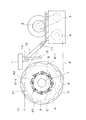
- FIG. 1 is a side view showing an escalator according to Embodiment 1 of the present invention.
- FIG. 2 is an enlarged view showing a main part of the escalator of FIG.
- An escalator which is a passenger conveyor, includes a main frame 1 provided over an upper floor and a lower floor, a motor 2 provided on the main frame 1, and a deceleration to which the power of the motor 2 is transmitted. And a drive sprocket 4 to which the power of the motor 2 is transmitted via the speed reducer 3.
- the motor 2, the speed reducer 3, and the drive sprocket 4 are arranged on the upper floor horizontal portion of the main frame 1. When the power of the motor 2 is transmitted to the driving sprocket 4, the driving sprocket 4 rotates.
- the escalator includes a drive chain 5 wound around the drive sprocket 4, a main sprocket 6 wound around the drive chain 5, and a main shaft 7 fixed to the main sprocket 6.
- the drive chain 5, the main sprocket 6, and the main shaft 7 are arranged on a horizontal portion on the upper floor side of the main frame 1.
- the rotation of the drive sprocket 4 causes the drive chain 5 to circulate.
- the main sprocket 6 rotates.
- the main shaft 7 rotates.
- the escalator includes a ratchet wheel 8 fixed to the main shaft 7 and an upper step sprocket 9 fixed to the main shaft 7.
- the ratchet wheel 8 and the upper step sprocket 9 are arranged on a horizontal portion on the upper floor side of the main frame 1.
- the escalator also includes a step chain 10 wound around the upper step sprocket 9 and circulating, and a lower step sprocket 11 around which the step chain 10 is wound.
- the lower step sprocket 11 is arranged on a lower horizontal portion of the main frame 1.
- the upper step sprocket 9 rotates.
- the lower step sprocket 11 rotates and the step chain 10 circulates.
- the escalator also includes a plurality of steps 12 provided on the main frame 1 and a pair of balustrades 13 provided to face each other in the width direction of the steps 12.
- the plurality of steps 12 are connected to each other by a step chain 10. As the step chain 10 circulates, a plurality of steps 12 circulate.
- the escalator is supported by the connecting shaft 14 rotatably supported by the main frame 1, a ratchet pole 15 fixed to the connecting shaft 14, a shoe lever 16 fixed to the connecting shaft 14, and a shoe lever 16.
- the connection shaft 14 is arranged to extend along the main shaft 7.
- the ratchet pawl 15 is displaced between a braking position where the ratchet pawl 15 hits the ratchet wheel 8 and a release position where the ratchet pawl 15 separates from the ratchet wheel 8.
- the ratchet pole 15 is displaced between the braking position and the release position by the rotation of the connection shaft 14. When the ratchet pole 15 hits the ratchet wheel 8, the rotation of the ratchet wheel 8 is prevented.
- the shoe 17 is placed on the drive chain 5.
- the shoe 17 moves downward.
- the shoe lever 16 rotates.
- the rotation of the shoe lever 16 causes the connection shaft 14 to rotate. Therefore, when the drive chain 5 is broken, the ratchet pawl 15 moves from the release position to the braking position.
- the ratchet wheel 8 has an annular wheel body 81 having a plurality of teeth 811 formed on an outer peripheral portion, an annular boss 82 fixed to the main shaft 7, and brakes rotation of the boss 82 with respect to the wheel body 81. And a rotation braking unit 83.
- the ratchet pole 15 hits the teeth 811. Thereby, rotation of the wheel main body 81 is prevented.
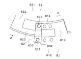
- FIG. 3 is an enlarged view showing a portion A in FIG.
- the boss 82 has a boss body 821 formed in an annular shape, a radial extension 822 extending radially outward from an outer peripheral portion of the boss main body 821, and a periphery extending in the circumferential direction D from a distal end of the radial extension 822. And a direction extending portion 823.
- the circumferential direction D in which the circumferential extending portion 823 extends is the rotation direction of the ratchet wheel 8.
- the boss 82 includes a plurality of radially extending portions 822 and a plurality of circumferentially extending portions 823.
- the plurality of radially extending portions 822 and the plurality of circumferentially extending portions 823 are arranged at equal intervals in the circumferential direction.
- the wheel body 81 includes a wheel portion 812 having teeth 811 formed thereon, a radially extending portion 813 extending radially inward from an inner peripheral portion of the wheel portion 812, and a distal end of the radially extending portion 813. And a circumferentially extending portion 814 extending in the circumferential direction E from the portion.
- the circumferential direction E in which the circumferential extending portion 814 extends is opposite to the rotational direction of the ratchet wheel 8.
- the wheel main body 81 includes a plurality of radially extending portions 813 and a plurality of circumferentially extending portions 814.
- the plurality of radially extending portions 813 and the plurality of circumferentially extending portions 814 are arranged at equal intervals in the circumferential direction.
- a circumferential extension 814 is arranged between the boss body 821 and the circumferential extension 823.
- a circumferential extension 823 is arranged between the wheel 812 and the circumferential extension 814.
- the rotation braking unit 83 includes a friction member 831 provided on the wheel body 81.
- the friction member 831 includes a pair of friction plates 832 provided over the wheel portion 812 and the circumferentially extending portion 814, and fastening for fixing the pair of friction plates 832 to the wheel portion 812 and the circumferentially extending portion 814.
- Tool 833 The pair of friction plates 832 are arranged so as to sandwich the boss 82 in the thickness direction of the boss 82.
- the pair of friction plates 832 is in contact with both side surfaces of the circumferentially extending portion 823.
- the pair of friction plates 832 are provided at four portions of the wheel body 81 which are arranged at equal intervals in the circumferential direction.
- the wheel body 81 is held by the boss 82 by the frictional force of the friction plate 832 against the side surface of the circumferentially extending portion 823. By holding the wheel body 81 on the boss 82, the wheel body 81 rotates together with the boss 82 when the ratchet pole 15 does not hit the teeth 811.
- the fastener 833 is composed of a bolt and a nut.
- FIG. 4 is an enlarged view showing a portion B in FIG.
- the friction member 831 includes a pair of friction plates 834 provided over the wheel portion 812 and the circumferential extension 814, and fastening for fixing the pair of friction plates 834 to the wheel portion 812 and the circumferential extension 814.
- Tool 835 The pair of friction plates 834 are arranged so as to sandwich the boss 82 in the thickness direction of the boss 82.
- the pair of friction plates 834 are disposed forward of the circumferentially extending portion 823 in the rotation direction of the ratchet wheel 8 when the ratchet pole 15 does not contact the teeth 811.
- the circumferentially extending portion 823 is disposed between the pair of friction plates 834.
- the pair of friction plates 834 contact both side surfaces of the circumferentially extending portion 823. Therefore, the friction member 831 is arranged so that the area of the side surface of the boss 82 that contacts the friction member 831 increases as the boss 82 rotates relative to the wheel body 81 in the rotation direction of the ratchet wheel 8. .
- a pair of friction plates 834 are provided at each of two portions of the wheel body 81 that sandwich the main shaft 7.
- the fastener 835 includes a bolt and a nut.
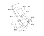
- FIG. 5 is an enlarged view showing a portion C in FIG.
- the friction member 831 is provided with a pair of friction plates 836 provided over the wheel portion 812 and the circumferentially extending portion 814, and fastening the pair of friction plates 836 to the wheel portion 812 and the circumferentially extending portion 814.
- Tool 837 The pair of friction plates 836 are arranged so as to sandwich the boss 82 in the thickness direction of the boss 82.
- the pair of friction plates 836 are arranged forward of the circumferentially extending portion 823 in the rotation direction of the ratchet wheel 8 when the ratchet pole 15 does not contact the teeth 811.
- the pair of friction plates A circumferentially extending portion 823 is arranged between 836.
- the pair of friction plates 836 contact both side surfaces of the circumferentially extending portion 823. Therefore, the friction member 831 is arranged so that the area of the side surface of the boss 82 that contacts the friction member 831 increases as the boss 82 rotates relative to the wheel body 81 in the rotation direction of the ratchet wheel 8. .
- a pair of friction plates 836 are provided at each of two portions of the wheel main body 81 that sandwich the main shaft 7.
- the fastener 837 includes a bolt and a nut.
- the emergency braking device of the escalator includes a ratchet wheel 8, a connecting shaft 14, a ratchet pole 15, a shoe lever 16, and a shoe 17.
- the boss 82 rotates with respect to the wheel body 81 by preventing the rotation of the wheel body 81.
- the circumferentially extending portion 823 is disposed between the pair of friction plates 834.
- the boss 82 further rotates with respect to the wheel body 81.
- the circumferentially extending portion 823 is disposed between the pair of friction plates 836.
- the boss 82 further rotates with respect to the wheel body 81.
- the circumferential extension 823 hits the radial extension 813
- the circumferential extension 814 hits the radial extension 822.
- the boss 82 contacts the wheel main body 81 in the rotation direction of the ratchet wheel 8.
- the rotation of the boss 82 with respect to the wheel body 81 is stopped.
- the rotation of the main shaft 7 is stopped.
- the movement of the steps 12 is stopped.
- ratchet wheel 8 includes wheel body 81, boss 82 fixed to main shaft 7, and boss 82 for wheel body 81. And a rotation braking unit 83 that brakes the rotation of.
- the rotation braking unit 83 has a friction member 831 provided on the wheel body 81 and in contact with the side surface of the boss 82.
- the friction member 831 is arranged such that the area of the boss 82 that contacts the friction member 831 increases as the boss 82 rotates with respect to the wheel body 81. Accordingly, the braking force acting on the main shaft 7 when the ratchet pole 15 hits the teeth 811 can be made larger as the main shaft 7 rotates with respect to the teeth 811.
- the ratchet wheel 8 includes a wheel body 81 formed in an annular shape, a boss 82 formed in an annular shape, and a rotation braking unit 83. Thereby, the structure of the ratchet wheel 8 can be simplified as compared with a conventional ratchet wheel having four annular disks.
- Friction member 831 contacts both side surfaces of boss 82. Thereby, the frictional force of the friction member 831 on the boss 82 can be increased.
- an escalator has been described as an example of the passenger conveyor.
- the present invention is not limited to this, and may be a moving sidewalk.
- the configuration in which the friction member 831 is provided on the wheel main body 81 has been described.
- the configuration is not limited thereto, and the friction member 831 may be provided on the boss 82. In this case, the friction member 831 contacts the side surface of the circumferentially extending portion 814.
- the friction member 831 includes the friction plate 832, the friction plate 834, and the friction plate 836 has been described.
- the friction member 831 has a configuration in which the area of the side surface of the boss 82 that contacts the friction member 831 increases as the boss 82 rotates with respect to the wheel body 81 in the rotation direction of the ratchet wheel 8. I just need.
Landscapes
- Escalators And Moving Walkways (AREA)
- Braking Arrangements (AREA)
Abstract
ラチェットポールが歯に当たった場合に主軸に作用する制動力を、歯に対して主軸が回転するにつれてより大きくするとともに、ラチェットホイールの構造を簡単化することができるエスカレータの非常制動装置を得る。このエスカレータの非常制動装置は、主軸に設けられたラチェットホイールを備え、ラチェットホイールは、ホイール本体と、主軸に固定されたボスと、ホイール本体に対するボスの回転を制動する回転制動部とを有し、回転制動部は、ホイール本体に設けられボスの側面に接触する摩擦部材を有し、摩擦部材は、ホイール本体に対してボスが回転するにつれて、ボスの側面における摩擦部材に接触される面積が大きくなるように、配置されている。
Description
この発明は、ラチェットホイールを備えた乗客コンベヤの非常制動装置に関する。
従来、主軸に設けられたラチェットホイールと、ラチェットホイールの回転を阻止するラチェットポールとを備えたエスカレータの非常制動装置が知られている。ラチェットホイールは、主軸を中心に径方向に隙間をあけて順に設けられた4個の円環形状の円板と、径方向に互いに隣接した円板の隙間に設けられ、径方向に互いに隣接した円板の間に摩擦力を発生させる摩擦部材とを有している。4個の円板の中で最も径方向内側に配置された円板は、主軸に固定されている。4個の円板の中で最も径方向外側に配置された円板には、ラチェットポールが当たる複数の歯が形成されている。ラチェットポールが歯に当たった場合に主軸に作用する制動力は、歯に対して主軸が回転するにつれてより大きくなる(例えば、特許文献1参照)。
しかしながら、特許文献1に記載のエスカレータの非常制動装置では、ラチェットホイールの構造が複雑であるという課題があった。
この発明は、上述のような課題を解決するためになされたものであり、その目的は、ラチェットポールが歯に当たった場合に主軸に作用する制動力を、歯に対して主軸が回転するにつれてより大きくするとともに、ラチェットホイールの構造を簡単化することができる乗客コンベヤの非常制動装置を提供するものである。
この発明に係る乗客コンベヤの非常制動装置は、主軸に設けられたラチェットホイールと、ラチェットホイールの回転を阻止するラチェットポールとを備え、ラチェットホイールは、外周部に複数の歯が形成されたホイール本体と、主軸に固定されたボスと、ホイール本体に対するボスの回転を制動する回転制動部とを有し、回転制動部は、ホイール本体およびボスの何れか一方に設けられ、ホイール本体およびボスの他方の側面に接触する摩擦部材を有し、摩擦部材は、ラチェットホイールの回転方向についてホイール本体に対してボスが回転するにつれて、他方の側面における摩擦部材に接触される面積が大きくなるように、配置されている。
この発明に係る乗客コンベヤの非常制動装置によれば、摩擦部材は、ラチェットホイールの回転方向についてホイール本体に対してボスが回転するにつれて、他方の側面における摩擦部材に接触される面積が大きくなるように、配置されている。これにより、ラチェットポールが歯に当たった場合に主軸に作用する制動力を、歯に対して主軸が回転するにつれてより大きくするとともに、ラチェットホイールの構造を簡単化することができる。
実施の形態1.
図1は、この発明の実施の形態1に係るエスカレータを示す側面図である。図2は、図1のエスカレータの要部を示す拡大図である。乗客コンベヤであるエスカレータは、上階側階床と下階側階床とに渡って設けられた主枠1と、主枠1に設けられたモータ2と、モータ2の動力が伝達される減速機3と、減速機3を介してモータ2の動力が伝達される駆動スプロケット4とを備えている。モータ2、減速機3および駆動スプロケット4は、主枠1における上階側水平部に配置されている。モータ2の動力が駆動スプロケット4に伝達されることによって、駆動スプロケット4が回転する。
図1は、この発明の実施の形態1に係るエスカレータを示す側面図である。図2は、図1のエスカレータの要部を示す拡大図である。乗客コンベヤであるエスカレータは、上階側階床と下階側階床とに渡って設けられた主枠1と、主枠1に設けられたモータ2と、モータ2の動力が伝達される減速機3と、減速機3を介してモータ2の動力が伝達される駆動スプロケット4とを備えている。モータ2、減速機3および駆動スプロケット4は、主枠1における上階側水平部に配置されている。モータ2の動力が駆動スプロケット4に伝達されることによって、駆動スプロケット4が回転する。
また、エスカレータは、駆動スプロケット4に巻き掛けられたドライブチェーン5と、ドライブチェーン5が巻き掛けられたメインスプロケット6と、メインスプロケット6に対して固定された主軸7とを備えている。ドライブチェーン5、メインスプロケット6および主軸7は、主枠1における上階側水平部に配置されている。駆動スプロケット4が回転することによって、ドライブチェーン5が循環移動する。ドライブチェーン5が循環移動することによって、メインスプロケット6が回転する。メインスプロケット6が回転することによって、主軸7が回転する。
また、エスカレータは、主軸7に対して固定されたラチェットホイール8と、主軸7に対して固定された上部踏段スプロケット9とを備えている。ラチェットホイール8および上部踏段スプロケット9は、主枠1における上階側水平部に配置されている。また、エスカレータは、上部踏段スプロケット9に巻き掛けられ循環移動する踏段チェーン10と、踏段チェーン10が巻き掛けられた下部踏段スプロケット11とを備えている。下部踏段スプロケット11は、主枠1における下階側水平部に配置されている。主軸7が回転することによって、上部踏段スプロケット9が回転する。上部踏段スプロケット9が回転することによって、下部踏段スプロケット11が回転するとともに、踏段チェーン10が循環移動する。
また、エスカレータは、主枠1に設けられた複数の踏段12と、踏段12の幅方向について互いに対向して設けられた一対の欄干13とを備えている。複数の踏段12は、踏段チェーン10によって互いに連結されている。踏段チェーン10が循環移動することによって、複数の踏段12が循環移動する。
また、エスカレータは、主枠1に回転可能に支持された連結軸14と、連結軸14に固定されたラチェットポール15と、連結軸14に固定されたシューレバー16と、シューレバー16に支持されたシュー17とを備えている。連結軸14は、主軸7に沿って延びて配置されている。ラチェットポール15は、ラチェットポール15がラチェットホイール8に当たる制動位置と、ラチェットポール15がラチェットホイール8から離れる解除位置との間で変位する。ラチェットポール15は、連結軸14が回転することによって、制動位置と解除位置との間で変位する。ラチェットポール15がラチェットホイール8に当たることによって、ラチェットホイール8の回転が阻止される。
シュー17は、ドライブチェーン5の上に載せられている。ドライブチェーン5が破断した場合に、シュー17が下方に移動する。シュー17が下方に移動することによって、シューレバー16が回転する。シューレバー16が回転することによって、連結軸14が回転する。したがって、ドライブチェーン5が破断した場合に、ラチェットポール15が解除位置から制動位置に移動する。
ラチェットホイール8は、外周部に複数の歯811が形成された円環形状のホイール本体81と、主軸7に固定された円環形状のボス82と、ホイール本体81に対するボス82の回転を制動する回転制動部83とを備えている。ラチェットポール15の位置が制動位置である場合に、ラチェットポール15が歯811に当たる。これにより、ホイール本体81の回転が阻止される。
図3は、図2のA部を示す拡大図である。ボス82は、円環形状に形成されたボス本体821と、ボス本体821の外周部から径方向外側に延びる径方向延部822と、径方向延部822の先端部から周方向Dに延びる周方向延部823とを備えている。周方向延部823が延びる周方向Dは、ラチェットホイール8の回転方向となっている。図2に示すように、ボス82は、複数の径方向延部822および複数の周方向延部823を備えている。複数の径方向延部822および複数の周方向延部823は、周方向に等間隔に並べて配置されている。
図3に示すように、ホイール本体81は、歯811が形成されたホイール部812と、ホイール部812の内周部から径方向内側に延びる径方向延部813と、径方向延部813の先端部から周方向Eに延びる周方向延部814とを備えている。周方向延部814が延びる周方向Eは、ラチェットホイール8の回転方向とは反対の方向となっている。図2に示すように、ホイール本体81は、複数の径方向延部813および複数の周方向延部814を備えている。複数の径方向延部813および複数の周方向延部814は、周方向に等間隔に並べて配置されている。
図3に示すように、ボス本体821と周方向延部823との間に周方向延部814が配置されている。ホイール部812と周方向延部814との間に周方向延部823が配置されている。
回転制動部83は、ホイール本体81に設けられた摩擦部材831を備えている。摩擦部材831は、ホイール部812と周方向延部814とに渡って設けられた一対の摩擦板832と、一対の摩擦板832をホイール部812および周方向延部814に対して固定する締付具833とを備えている。一対の摩擦板832は、ボス82の板厚方向についてボス82を挟むように配置されている。一対の摩擦板832は、周方向延部823の両側面に接触している。一対の摩擦板832は、ホイール本体81における周方向に等間隔に並べられた4箇所の部分のそれぞれに設けられている。周方向延部823の側面に対する摩擦板832の摩擦力によって、ホイール本体81がボス82に保持される。ホイール本体81がボス82に保持されることによって、ラチェットポール15が歯811に当たっていない場合に、ホイール本体81がボス82とともに回転する。締付具833は、ボルトと、ナットとから構成されている。
図4は、図2のB部を示す拡大図である。摩擦部材831は、ホイール部812と周方向延部814とに渡って設けられた一対の摩擦板834と、一対の摩擦板834をホイール部812および周方向延部814に対して固定する締付具835とを備えている。一対の摩擦板834は、ボス82の板厚方向についてボス82を挟むように配置されている。一対の摩擦板834は、ラチェットポール15が歯811に当たっていない場合に、ラチェットホイール8の回転方向について周方向延部823よりも前方側に配置される。ホイール本体81に対してボス82が回転した場合に、一対の摩擦板834の間に周方向延部823が配置される。この場合に、一対の摩擦板834は、周方向延部823の両側面に接触する。したがって、摩擦部材831は、ラチェットホイール8の回転方向についてホイール本体81に対してボス82が回転するにつれて、ボス82の側面における摩擦部材831に接触される面積が大きくなるように、配置されている。一対の摩擦板834は、ホイール本体81における主軸7を挟む2箇所の部分のそれぞれに設けられている。締付具835は、ボルトと、ナットとから構成されている。
図5は、図2のC部を示す拡大図である。摩擦部材831は、ホイール部812と周方向延部814とに渡って設けられた一対の摩擦板836と、一対の摩擦板836をホイール部812および周方向延部814に対して固定する締付具837とを備えている。一対の摩擦板836は、ボス82の板厚方向についてボス82を挟むように配置されている。一対の摩擦板836は、ラチェットポール15が歯811に当たっていない場合に、ラチェットホイール8の回転方向について周方向延部823よりも前方側に配置される。ホイール本体81に対してボス82が回転し、一対の摩擦板834の間に周方向延部823が配置され、その後、さらにホイール本体81に対してボス82が回転した場合に、一対の摩擦板836の間に周方向延部823が配置される。この場合に、一対の摩擦板836は、周方向延部823の両側面に接触する。したがって、摩擦部材831は、ラチェットホイール8の回転方向についてホイール本体81に対してボス82が回転するにつれて、ボス82の側面における摩擦部材831に接触される面積が大きくなるように、配置されている。一対の摩擦板836は、ホイール本体81における主軸7を挟む2箇所の部分のそれぞれに設けられている。締付具837は、ボルトと、ナットとから構成されている。
エスカレータの非常制動装置は、ラチェットホイール8と、連結軸14と、ラチェットポール15と、シューレバー16と、シュー17とから構成されている。
次に、エスカレータの非常制動装置の動作について説明する。ドライブチェーン5が破断した場合には、ラチェットポール15が解除位置から制動位置に移動する。これにより、ホイール本体81の歯811がラチェットポール15に当たる。その結果、ホイール本体81の回転が阻止される。
ホイール本体81の回転が阻止されることによって、ホイール本体81に対してボス82が回転する。これにより、周方向延部823が一対の摩擦板834の間に配置される。その結果、ラチェットホイール8の回転方向についてホイール本体81に対してボス82が回転するにつれて、ボス82の側面における摩擦部材831に接触される面積が大きくなる。これにより、ラチェットホイール8の回転方向についてホイール本体81に対してボス82が回転するにつれて、ボス82の側面と摩擦部材831との間に発生する摩擦力が大きくなる。したがって、回転制動部83による主軸7の制動力が大きくなる。
その後、さらにホイール本体81に対してボス82が回転する。これにより、周方向延部823が一対の摩擦板836の間に配置される。その結果、ラチェットホイール8の回転方向についてホイール本体81に対してボス82が回転するにつれて、ボス82の側面における摩擦部材831に接触される面積がさらに大きくなる。これにより、ラチェットホイール8の回転方向についてホイール本体81に対してボス82が回転するにつれて、ボス82の側面と摩擦部材831との間に発生する摩擦力がさらに大きくなる。したがって、回転制動部83による主軸7の制動力がさらに大きくなる。
その後、さらにホイール本体81に対してボス82が回転する。これにより、周方向延部823が径方向延部813に当たり、また、周方向延部814が径方向延部822に当たる。言い換えれば、ラチェットホイール8の回転方向についてホイール本体81に対してボス82が当たる。これにより、ホイール本体81に対するボス82の回転が停止される。その結果、主軸7の回転が停止される。これにより、踏段12の移動が停止される。
以上説明したように、この発明の実施の形態1に係るエスカレータの非常制動装置によれば、ラチェットホイール8は、ホイール本体81と、主軸7に固定されたボス82と、ホイール本体81に対するボス82の回転を制動する回転制動部83とを有している。回転制動部83は、ホイール本体81に設けられボス82の側面に接触する摩擦部材831を有している。摩擦部材831は、ホイール本体81に対してボス82が回転するにつれて、ボス82における摩擦部材831に接触される面積が大きくなるように、配置されている。これにより、ラチェットポール15が歯811に当たった場合に主軸7に作用する制動力を、歯811に対して主軸7が回転するにつれてより大きくすることができる。その結果、エスカレータの非常制動装置が踏段12の移動を停止させる時の乗客への衝撃を緩和させることができる。また、ラチェットホイール8は、円環形状に形成されたホイール本体81と、円環形状に形成されたボス82と、回転制動部83とを有している。これにより、4個の円環形状の円板を有する従来のラチェットホイールと比較して、ラチェットホイール8の構造を簡単化することができる。
また、摩擦部材831は、ボス82の両側面に接触する。これにより、ボス82に対する摩擦部材831の摩擦力を増加させることができる。
なお、上記実施の形態1では、乗客コンベヤとしてエスカレータを例に説明した。しかしながら、これに限らず、動く歩道であってもよい。
また、上記実施の形態1では、摩擦部材831がホイール本体81に設けられた構成について説明した。しかしながら、これに限らず、摩擦部材831がボス82に設けられた構成であってもよい。この場合、摩擦部材831は、周方向延部814の側面に接触する。
また、上記実施の形態1では、摩擦部材831が、摩擦板832、摩擦板834および摩擦板836を備えた構成について説明した。しかしながら、これに限らず、摩擦部材831は、ラチェットホイール8の回転方向についてホイール本体81に対してボス82が回転するにつれて、ボス82の側面における摩擦部材831に接触される面積が大きくなる構成であればよい。
1 主枠、2 モータ、3 減速機、4 駆動スプロケット、5 ドライブチェーン、6 メインスプロケット、7 主軸、8 ラチェットホイール、9 上部踏段スプロケット、10 踏段チェーン、11 下部踏段スプロケット、12 踏段、13 欄干、14 連結軸、15 ラチェットポール、16 シューレバー、17 シュー、81 ホイール本体、82 ボス、83 回転制動部、811 歯、812 ホイール部、813 径方向延部、814 周方向延部、821 ボス本体、822 径方向延部、823 周方向延部、831 摩擦部材、832 摩擦板、833 締付具、834 摩擦板、835 締付具、836 摩擦板、837 締付具。
Claims (2)
- 主軸に設けられたラチェットホイールと、
前記ラチェットホイールの回転を阻止するラチェットポールと
を備え、
前記ラチェットホイールは、
外周部に複数の歯が形成されたホイール本体と、
前記主軸に固定されたボスと、
前記ホイール本体に対する前記ボスの回転を制動する回転制動部と
を有し、
前記回転制動部は、前記ホイール本体および前記ボスの何れか一方に設けられ、前記ホイール本体および前記ボスの他方の側面に接触する摩擦部材を有し、
前記摩擦部材は、前記ラチェットホイールの回転方向について前記ホイール本体に対して前記ボスが回転するにつれて、前記他方の側面における前記摩擦部材に接触される面積が大きくなるように、配置されている乗客コンベヤの非常制動装置。 - 前記摩擦部材は、前記他方の両側面に接触する請求項1に記載の乗客コンベヤの非常制動装置。
Priority Applications (3)
| Application Number | Priority Date | Filing Date | Title |
|---|---|---|---|
| PCT/JP2018/034245 WO2020054065A1 (ja) | 2018-09-14 | 2018-09-14 | 乗客コンベヤの非常制動装置 |
| JP2020546660A JP6949240B2 (ja) | 2018-09-14 | 2018-09-14 | 乗客コンベヤの非常制動装置 |
| CN201880097261.6A CN112654577B (zh) | 2018-09-14 | 2018-09-14 | 乘客输送机的紧急制动装置 |
Applications Claiming Priority (1)
| Application Number | Priority Date | Filing Date | Title |
|---|---|---|---|
| PCT/JP2018/034245 WO2020054065A1 (ja) | 2018-09-14 | 2018-09-14 | 乗客コンベヤの非常制動装置 |
Publications (1)
| Publication Number | Publication Date |
|---|---|
| WO2020054065A1 true WO2020054065A1 (ja) | 2020-03-19 |
Family
ID=69777732
Family Applications (1)
| Application Number | Title | Priority Date | Filing Date |
|---|---|---|---|
| PCT/JP2018/034245 Ceased WO2020054065A1 (ja) | 2018-09-14 | 2018-09-14 | 乗客コンベヤの非常制動装置 |
Country Status (3)
| Country | Link |
|---|---|
| JP (1) | JP6949240B2 (ja) |
| CN (1) | CN112654577B (ja) |
| WO (1) | WO2020054065A1 (ja) |
Citations (6)
| Publication number | Priority date | Publication date | Assignee | Title |
|---|---|---|---|---|
| JPS62269880A (ja) * | 1986-05-14 | 1987-11-24 | 三菱電機株式会社 | 乗客コンベヤの非常制動装置 |
| JP2010127314A (ja) * | 2008-11-25 | 2010-06-10 | Sinfonia Technology Co Ltd | トルク伝達装置 |
| JP2013227117A (ja) * | 2012-04-25 | 2013-11-07 | Mitsubishi Electric Corp | マンコンベア |
| JP2016102019A (ja) * | 2014-11-28 | 2016-06-02 | 三菱電機ビルテクノサービス株式会社 | 乗客コンベヤのラチェットホイール用歯装置 |
| JP2016222424A (ja) * | 2015-06-01 | 2016-12-28 | 三菱電機株式会社 | 乗客コンベアの非常制動装置 |
| EP3354615A1 (en) * | 2017-01-31 | 2018-08-01 | thyssenkrupp Elevator AG | Driving system for driving a conveyer band of a conveyer apparatus |
Family Cites Families (4)
| Publication number | Priority date | Publication date | Assignee | Title |
|---|---|---|---|---|
| GB8703874D0 (en) * | 1987-02-19 | 1987-03-25 | Smiths Industries Plc | Ostomy bags & materials |
| CN1664400A (zh) * | 2005-03-29 | 2005-09-07 | 高自强 | 蹄式气动制动器 |
| JP2012025570A (ja) * | 2010-07-27 | 2012-02-09 | Toshiba Elevator Co Ltd | 乗客コンベアのブレーキ装置 |
| JP2012144351A (ja) * | 2011-01-13 | 2012-08-02 | Toshiba Elevator Co Ltd | 乗客コンベア |
-
2018
- 2018-09-14 WO PCT/JP2018/034245 patent/WO2020054065A1/ja not_active Ceased
- 2018-09-14 CN CN201880097261.6A patent/CN112654577B/zh active Active
- 2018-09-14 JP JP2020546660A patent/JP6949240B2/ja active Active
Patent Citations (6)
| Publication number | Priority date | Publication date | Assignee | Title |
|---|---|---|---|---|
| JPS62269880A (ja) * | 1986-05-14 | 1987-11-24 | 三菱電機株式会社 | 乗客コンベヤの非常制動装置 |
| JP2010127314A (ja) * | 2008-11-25 | 2010-06-10 | Sinfonia Technology Co Ltd | トルク伝達装置 |
| JP2013227117A (ja) * | 2012-04-25 | 2013-11-07 | Mitsubishi Electric Corp | マンコンベア |
| JP2016102019A (ja) * | 2014-11-28 | 2016-06-02 | 三菱電機ビルテクノサービス株式会社 | 乗客コンベヤのラチェットホイール用歯装置 |
| JP2016222424A (ja) * | 2015-06-01 | 2016-12-28 | 三菱電機株式会社 | 乗客コンベアの非常制動装置 |
| EP3354615A1 (en) * | 2017-01-31 | 2018-08-01 | thyssenkrupp Elevator AG | Driving system for driving a conveyer band of a conveyer apparatus |
Also Published As
| Publication number | Publication date |
|---|---|
| JP6949240B2 (ja) | 2021-10-13 |
| CN112654577A (zh) | 2021-04-13 |
| JPWO2020054065A1 (ja) | 2021-01-07 |
| CN112654577B (zh) | 2023-05-12 |
Similar Documents
| Publication | Publication Date | Title |
|---|---|---|
| CN103241636B (zh) | 乘客输送机 | |
| KR940001404Y1 (ko) | 에스컬레이터의 주축 브레이크장치 | |
| JP2010018419A (ja) | 乗客コンベア | |
| JP6238868B2 (ja) | 乗客コンベヤの非常制動装置 | |
| EP3071502B1 (en) | Brake for use in passenger conveyor system | |
| JP2008001470A (ja) | 乗客コンベアの補助ブレーキ装置 | |
| JP5924673B2 (ja) | マンコンベア | |
| WO2020054065A1 (ja) | 乗客コンベヤの非常制動装置 | |
| JP6289259B2 (ja) | エスカレータの非常制動装置およびエスカレータ | |
| JP2015037996A (ja) | 乗客コンベアのブレーキ装置 | |
| JP6253777B2 (ja) | 乗客コンベヤの安全装置 | |
| TWI299319B (ja) | ||
| JP2010503593A (ja) | 複合材料製ブレーキハブを有するエレベータブレーキ | |
| WO2018011960A1 (ja) | 乗客コンベアの安全装置 | |
| JP6335766B2 (ja) | 乗客コンベヤのラチェットホイール用歯装置 | |
| JP5645326B1 (ja) | 乗客コンベアのブレーキ装置 | |
| JP2014088221A (ja) | 乗客コンベア | |
| CN121591091A (zh) | 附加制动器及自动扶梯、自动人行道 | |
| KR100509413B1 (ko) | 완강기 | |
| JP4446834B2 (ja) | 電動式ブレーキ装置 | |
| WO2025057261A1 (ja) | 回転体及びエレベーター巻上機 | |
| KR20210125641A (ko) | 에스컬레이터 역주행 방지장치 | |
| JPS5919141Y2 (ja) | ラチエツト装置 | |
| KR20220028738A (ko) | 비상 제동 가능한 에스컬레이터 | |
| CN100526191C (zh) | 电梯的曳引机 |
Legal Events
| Date | Code | Title | Description |
|---|---|---|---|
| 121 | Ep: the epo has been informed by wipo that ep was designated in this application |
Ref document number: 18933603 Country of ref document: EP Kind code of ref document: A1 |
|
| ENP | Entry into the national phase |
Ref document number: 2020546660 Country of ref document: JP Kind code of ref document: A |
|
| NENP | Non-entry into the national phase |
Ref country code: DE |
|
| 122 | Ep: pct application non-entry in european phase |
Ref document number: 18933603 Country of ref document: EP Kind code of ref document: A1 |