WO2020050176A1 - キャップ付き容器 - Google Patents
キャップ付き容器 Download PDFInfo
- Publication number
- WO2020050176A1 WO2020050176A1 PCT/JP2019/034197 JP2019034197W WO2020050176A1 WO 2020050176 A1 WO2020050176 A1 WO 2020050176A1 JP 2019034197 W JP2019034197 W JP 2019034197W WO 2020050176 A1 WO2020050176 A1 WO 2020050176A1
- Authority
- WO
- WIPO (PCT)
- Prior art keywords
- cap
- container
- mouth
- magnet
- wall
- Prior art date
- Legal status (The legal status is an assumption and is not a legal conclusion. Google has not performed a legal analysis and makes no representation as to the accuracy of the status listed.)
- Ceased
Links
Images





Classifications
-
- B—PERFORMING OPERATIONS; TRANSPORTING
- B65—CONVEYING; PACKING; STORING; HANDLING THIN OR FILAMENTARY MATERIAL
- B65D—CONTAINERS FOR STORAGE OR TRANSPORT OF ARTICLES OR MATERIALS, e.g. BAGS, BARRELS, BOTTLES, BOXES, CANS, CARTONS, CRATES, DRUMS, JARS, TANKS, HOPPERS, FORWARDING CONTAINERS; ACCESSORIES, CLOSURES, OR FITTINGS THEREFOR; PACKAGING ELEMENTS; PACKAGES
- B65D41/00—Caps, e.g. crown caps or crown seals, i.e. members having parts arranged for engagement with the external periphery of a neck or wall defining a pouring opening or discharge aperture; Protective cap-like covers for closure members, e.g. decorative covers of metal foil or paper
- B65D41/02—Caps or cap-like covers without lines of weakness, tearing strips, tags, or like opening or removal devices
- B65D41/16—Snap-on caps or cap-like covers
- B65D41/18—Snap-on caps or cap-like covers non-metallic, e.g. made of paper or plastics
- B65D41/185—Snap-on caps or cap-like covers non-metallic, e.g. made of paper or plastics with integral internal sealing means
-
- A—HUMAN NECESSITIES
- A45—HAND OR TRAVELLING ARTICLES
- A45D—HAIRDRESSING OR SHAVING EQUIPMENT; EQUIPMENT FOR COSMETICS OR COSMETIC TREATMENTS, e.g. FOR MANICURING OR PEDICURING
- A45D34/00—Containers or accessories specially adapted for handling liquid toiletry or cosmetic substances, e.g. perfumes
-
- B—PERFORMING OPERATIONS; TRANSPORTING
- B65—CONVEYING; PACKING; STORING; HANDLING THIN OR FILAMENTARY MATERIAL
- B65D—CONTAINERS FOR STORAGE OR TRANSPORT OF ARTICLES OR MATERIALS, e.g. BAGS, BARRELS, BOTTLES, BOXES, CANS, CARTONS, CRATES, DRUMS, JARS, TANKS, HOPPERS, FORWARDING CONTAINERS; ACCESSORIES, CLOSURES, OR FITTINGS THEREFOR; PACKAGING ELEMENTS; PACKAGES
- B65D41/00—Caps, e.g. crown caps or crown seals, i.e. members having parts arranged for engagement with the external periphery of a neck or wall defining a pouring opening or discharge aperture; Protective cap-like covers for closure members, e.g. decorative covers of metal foil or paper
- B65D41/02—Caps or cap-like covers without lines of weakness, tearing strips, tags, or like opening or removal devices
- B65D41/28—Caps combined with stoppers
-
- B—PERFORMING OPERATIONS; TRANSPORTING
- B65—CONVEYING; PACKING; STORING; HANDLING THIN OR FILAMENTARY MATERIAL
- B65D—CONTAINERS FOR STORAGE OR TRANSPORT OF ARTICLES OR MATERIALS, e.g. BAGS, BARRELS, BOTTLES, BOXES, CANS, CARTONS, CRATES, DRUMS, JARS, TANKS, HOPPERS, FORWARDING CONTAINERS; ACCESSORIES, CLOSURES, OR FITTINGS THEREFOR; PACKAGING ELEMENTS; PACKAGES
- B65D45/00—Clamping or other pressure-applying devices for securing or retaining closure members
- B65D45/02—Clamping or other pressure-applying devices for securing or retaining closure members for applying axial pressure to engage closure with sealing surface
-
- B—PERFORMING OPERATIONS; TRANSPORTING
- B65—CONVEYING; PACKING; STORING; HANDLING THIN OR FILAMENTARY MATERIAL
- B65D—CONTAINERS FOR STORAGE OR TRANSPORT OF ARTICLES OR MATERIALS, e.g. BAGS, BARRELS, BOTTLES, BOXES, CANS, CARTONS, CRATES, DRUMS, JARS, TANKS, HOPPERS, FORWARDING CONTAINERS; ACCESSORIES, CLOSURES, OR FITTINGS THEREFOR; PACKAGING ELEMENTS; PACKAGES
- B65D2313/00—Connecting or fastening means
- B65D2313/04—Connecting or fastening means of magnetic type
Definitions
- the present invention relates to a container with a cap using magnetic force.
- Patent Literature 1 magnets are arranged so that different magnetic poles are opposed to each other around the entire contact portion between the cap and the container body when the lid is completely covered, and the magnets are magnetically attached to each other. (Patent Document 1).
- Patent Document 2 discloses a configuration in which a cap is hardly detached by providing a step in addition to the configuration by magnetic adhesion.
- Patent Literature 2 it is a container on the premise of containing solid or semi-solid contents such as lipstick, and is not assumed to contain a liquid because the contents are not sealed. . For this reason, if a liquid having a content is stored in a container having this configuration, even if the container and the cap maintain a closed state, the liquid may leak if the container is tilted or turned upside down.
- an object of the present invention is to provide a container with a cap that can easily attach and detach a cap and realize sealing between the cap and the container when the cap is mounted.
- a container with a cap comprising a container and a cap removably engaging the outer periphery of the mouth of the container, In the mouth, a hole penetrating vertically is formed, The cap is formed with a projecting plug extending downwardly from the ceiling wall, which is tightly fitted into the hole, Each of the mouth and the cap, provided between the mouth and the cap, a magnet that generates a magnetic force, Providing a container with a cap.
- the cap in a container with a cap, can be easily attached and detached, and the cap and the container can be hermetically sealed with the cap attached.
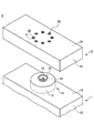
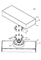
- FIG. 2 is a top perspective view showing a state where the cap and the container body of the first embodiment of the present invention are separated from each other.
- FIG. 3 is a bottom perspective view showing a state where the cap and the container body of the first embodiment are separated.
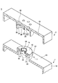
- FIG. 3 is a cross-sectional perspective view of the cap and the mouth of the container body according to the first embodiment. The figure which shows the magnetic pole of the magnet provided in the opening
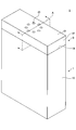
- FIG. 2 is a top perspective view showing the entire container with the cap closed in the container with a cap according to the first embodiment.
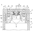
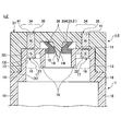
- FIG. 4 is a side cross-sectional view of the cap and the mouth of the container body according to the first embodiment.
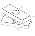
- FIG. 4 is a top perspective view showing a state where the cap of the first embodiment is rotated with respect to the mouth.
- FIG. 9 is an exploded view of the cap, the container body, and the magnet in the state of FIG. 8.
- the cap which has the plug part of the 1st modification, and a side sectional view of the mouth of the container main part.
- the side sectional view of the cap which has the plug part of the 2nd modification, and the mouth of the container main part.
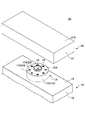
- the top perspective view showing the state where the cap and the container main part of a 2nd embodiment of the present invention were separated.
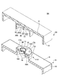
- FIG. 9 is a bottom perspective view showing a state where the cap and the container body of the second embodiment are separated.
- FIG. 10 is a top perspective view showing the entire container with the cap closed in the container with the cap according to the second embodiment.
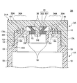
- FIG. 10 is a side cross-sectional view of the cap and the mouth of the container body according to the second embodiment. Explanatory drawing which shows the state of fitting in each state of the cap of 2nd Embodiment, and the opening part of a container main body.
- FIG. 10 is an exploded view of the cap, the container body, and the magnet in a state where the cap according to the second embodiment of the present invention is rotated with respect to the mouth of the container body.
- the present invention relates to a container with a cap using magnetic force.
- the container with a cap of the present invention includes, for example, cosmetics (basic cosmetics, base makeup cosmetics, point makeup cosmetics), cosmetics such as facial cleansers, hair styling, perfumes, and various liquids such as seasonings.
- the powder is stored.
- a substance (liquid or powder) containing a volatile component can be stored.
- FIG. 1 is a top perspective view showing a state where the cap 3 and the container body 1 of the first embodiment of the present invention are separated from each other.
- FIG. 2 is a bottom perspective view showing a state where the cap 3 and the container body 1 of the first embodiment are separated.
- FIG. 3 is a cross-sectional perspective view of the cap 3 and the mouth of the container body 1 according to the first embodiment.
- the container with cap (container with lid) 5 according to the embodiment of the present invention has the container body 1 and the cap (lid) 3.
- the container body 1 is a container capable of storing liquid or powder.
- the container body 1 is provided with a mouth 11 projecting upward from a shoulder 19. 1 to 3 show the mouth portion 11 and the shoulder portion 19, which are the upper side of the container body 1, and the housing portion 10 as the trunk extends below the shoulder portion 19. (See FIG. 5).
- the mouth portion 11 has a cylindrical shape having an upper surface, and has an upper wall 12 and a peripheral wall 13 as a side surface.
- a hole 14 is formed in the center of the upper wall 12 of the opening 11 so as to penetrate in the vertical direction.
- an abutting projection 15 is formed, which is recessed in a mortar shape (funnel shape) toward the hole 14 and protrudes upward in an annular shape on the upper wall 12.
- a ring-shaped magnet support band 16 is provided on the inner peripheral side of the peripheral end of the upper wall 12.
- the magnet support band 16 is thicker than other parts of the upper wall 12.
- the magnet support band 16 has a plurality of magnet insertion holes 17 opened downward.
- An annular rib 18 is further provided on the lower surface of the upper wall 12.
- the cap 3 is detachably attached to the mouth portion 11 of the container body 1 so as to be able to be tightly fitted.
- the outer surface of the cap 3 is constituted by a ceiling wall 31 and an outer wall 37.
- the cap 3 is provided with a hanging cylindrical wall 32 that hangs downward from the lower surface of the ceiling wall 31 in an annular shape.
- the cap 3 has a double side wall structure.
- the outer side is an outer side wall 37 and the inner side is a hanging cylindrical wall 32.
- a projecting plug also referred to as a boss, a sealing projection, or a sealing portion
- the plug 33 can be inserted into the hole 14 which is a fitting hole of the mouth 11.
- the plug portion 33 has a large diameter portion 331 located at the distal end portion and a shaft portion 332 which is a small diameter portion.
- the large diameter portion 331 has a larger diameter than the shaft portion 332 and is inserted into the hole portion 14. It will keep you from falling out when you do. Due to the shape of the plug portion 33, when the plug portion 33 is inserted into the hole portion 14, the plug portion 33 has a plugging structure, and the cap 3 hermetically seals the container body 1.
- FIG. 3 shows a state in which the magnet is removed from the mouth 11 and the cap 3.
- the lower surface sandwiched between the plug portion 33 and the magnet support band 34 is an abutting surface 36 that abuts against the abutting projection 15.
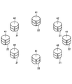
- FIG. 4 is a diagram showing the magnetic poles of the magnet provided on the cap 3 and the mouth 11 of the container body 1 of the present invention.
- a magnet that generates a magnetic force is provided between the mouth 11 and the cap 3 at each of the mouth 11 and the cap 3.
- annular magnet support band 16 is provided on the inner periphery of the peripheral end of the upper wall 12 of the mouth 11 of the container body 1.
- An annular magnet support band 34 is provided on the inner peripheral side of the hanging cylindrical wall 32 of the cap 3 so as to face the magnet support band 16 of the mouth 11.
- the magnets of the mouth portion 11 and the cap 3 are formed on the annular magnet support bands 16 and 34 by a plurality of homopolar portions (21, 41) arranged at equal intervals in a circumferential shape and a plurality of homopolar portions. It is formed by a plurality of other pole portions (22, 42) provided therebetween.
- N-pole magnets 21 and S-pole magnets 22 are alternately arranged in the mouth 11, and N-pole magnets 41 and S-pole magnets 42 are alternately arranged in the cap 3. Then, in a state in which the cap 3 is closed with respect to the mouth portion 11, as shown in FIG.
- the magnets are provided at every 45 degrees. Therefore, when the magnets are rotated by 45 degrees from the magnetized state, the magnets of the same polarity facing each other, that is, the N pole magnets 21 and 41 and the S pole A repulsive force acts between the magnets 22 and 42.
- FIG. 4 shows an example in which eight magnets are arranged at every 45 degrees in the mouth portion 11 and the cap 3, but the number of magnets is not limited to eight.
- the number of magnets on one surface is an even number so that magnets of different polarity are adjacent to each other.
- FIG. 5 is a top perspective view showing a state where the cap 3 and the container body 1 are closed in the container 5 with a cap according to the first embodiment.
- the container body 1 shown in FIGS. 1 to 3 has a shoulder portion 19 and a mouth portion 11 on the upper side of the container body 1, and a liquid is stored below the shoulder portion 19 as shown in FIG.
- the storage unit 10 is a bottomed square tubular body (bottle).
- the outer shape of the shoulder portion 19 of the container body 1 and the outer shape of the ceiling wall 31 of the cap 3 are substantially equal, when the cap is closed, the side surface of the cap 3 and the side surface of the container body 1 They overlap on the same plane.
- the magnets are arranged in an annular shape at intervals of 45 degrees, so that the attractive force is exerted by the outer shape. It is preferable that the state in which the repulsion works is distinguishable. Therefore, it is preferable that the ceiling wall 31 of the cap 3 is not a perfect circle in a top view, but a shape that can be determined to be rotated by 45 degrees, for example, a rectangle including a rectangle, a square, a diamond, or an ellipse. In addition, in the square, the corner may be rounded.
- FIG. 5 shows an example in which the ceiling wall 31 connected to the outer wall 37 in the cap 3 is substantially rectangular when viewed from above.
- the outer shape of the container body 1 as viewed from above is substantially rectangular
- the outer shape of the shoulder portion 19 of the container body 1 is different in shape and size from the shape of the cap 3. Is also good.
- the shape of the center of the shoulder 19 in top view should be the same as the center of the ceiling wall 31 of the cap 3. It is suitable.
- FIG. 5 shows an example in which the housing portion 10 has a substantially rectangular parallelepiped shape.
- the mouth portion 11 has a shape capable of engaging with the cap 3, and the housing portion 10 may have a bottom. Any shape may be used.
- the bottom (lower surface) of the housing 10 may be gradually widened or narrowed with respect to the shoulder 19 (upper surface), or the side of the housing 10 may be twisted, or the center of the trunk may be bent. It may have various shapes such as bulging or concave.
- FIG. 6 is a longitudinal sectional view of section A of FIG. 5 of the cap 3 and the mouth 11 of the container body 1 of the first embodiment.
- the hole 14 is formed in the upper wall 12 of the mouth 11 of the container body 1, and the butting protrusion 15, the annular rib 18, and the magnet support band 16 are provided.
- the hanging cylindrical wall 32 is a vertical section that is closest to the outermost square wall 37.
- the outside of the hanging cylindrical wall 32 and the inside of the outside wall 37 are integrated.
- a stopper 33 On the inner peripheral side of the hanging cylindrical wall 32 of the cap 3, a stopper 33, a magnet support band 34, and an abutting surface 36 are provided.
- the distal end of the plug portion 33 of the cap 3 is a large-diameter portion 331 having a larger diameter than the other portion, the shaft portion 332.
- the diameter of the inner wall 14I of the hole 14 of the mouth 11 is wider than the shaft 332 of the plug 33 and narrower than the large diameter 331.
- FIG. 6 shows an example in which the large-diameter portion 331 is provided at the tip (lower end) of the plug portion 33, but the large-diameter portion 331 extends from the upper end of the plug portion 33 to the thickness of the hole portion 14. It may be provided in an intermediate part other than the part.
- the shaft portion 332 may further extend below the large diameter portion 331.
- all the portions may be large-diameter portions 331 having a diameter larger than the inner wall 14I of the hole portion 14.
- the inner wall 14I of the hole 14 is made of a material that is elastically deformed. Therefore, at the time of insertion or withdrawal, the inner wall 14I is elastically deformed, so that the large-diameter portion 331, which is the tip of the plug 33, pushes through the hole 14.
- FIG. 6 shows an example in which the inner wall 14I of the mouth portion 11 is elastically deformed
- the outer shape of the large diameter portion 331 of the plug portion 33 may be elastically deformed instead of the inner wall 14I.
- both the inner wall 141 and the large diameter portion 331 may be elastically deformed.
- the outer circumference of the large diameter portion 331 is larger in diameter than the inner wall 141 of the hole portion 14 in a state in which the large diameter portion 331 is not elastically deformed. Since the sealed state between the cap 3 and the mouth 11 is not released, the contents do not leak even if the cap 3 is tilted, turned upside down, or shaken. Moreover, since the hanging cylindrical wall 32 is engaged so as to surround the outer periphery of the peripheral wall 13 of the mouth portion 11, it is unlikely to shift in the lateral direction.
- the upper surface of the magnet support band 16 of the mouth portion 11 is substantially flush with the upper surface of the upper wall 12, and the lower surface side of the upper wall is formed thick.
- the magnets 21 and 22 of the mouth 11 are inserted from below into a plurality of magnet insertion holes 17 opened downward on the lower surface of the magnet support band 16. Therefore, as shown in FIG. 6, a resin film is formed on the magnet 22 (21) on the upper surface of the upper wall 12 in the magnet support band 16 of the mouth portion 11 of the container body 1, that is, Since the resin remains in the upper portion without communicating vertically in the magnet insertion hole 17 of the magnet support band 16, the upper surface of the magnet 22 (21) is covered with the resin.
- the upper surface of the magnet support band 34 of the cap 3 is substantially flush with the upper surface of the ceiling wall 31, and is formed thicker on the lower surface side of the ceiling wall 31.
- the magnets 41 and 42 of the cap 3 are inserted into the plurality of magnet insertion holes 35 opened upward from above. Therefore, a resin film is formed under the magnet 41 (42). That is, the magnet insertion hole 35 of the magnet support band 34 does not communicate vertically and the resin remains at the lower part. On the lower surface of the magnet support band 34, the lower surface of the magnet 41 (42) is covered with resin.
- the magnets (22 (21) and 41 (42)) are covered by the resin in the portions that can be seen by the user in the state where the cap 3 is opened in both the mouth 11 and the cap 3. Therefore, the aesthetic appearance of the mouth portion 11 and the back surface of the cap 3 during use can be maintained.
- the lower part of the magnet insertion hole 17 of the magnet support band 16 on the container body 1 side is open and the upper part of the magnet insertion hole 35 of the magnet support band 34 on the cap 3 side is open.
- the inserted magnets 21 and 22 may come into contact with the liquid in the container. For this reason, the magnets 21 and 22 may be degraded by the liquid of the contents, or conversely, the components of the magnet, for example, alnico, ferrite, neodymium, samarium cobalt, etc. may flow out into the liquid, It is more preferable to cover the magnets 21 and 22 from below from the viewpoint of maintaining the quality of the liquid and safety.
- the magnets 41 and 42 are sealed with resin so that the magnets are hidden from both the front and rear surfaces of the cap 3 from the user. From the viewpoint of enhancing the aesthetic appearance, it is more preferable to cover the magnets 41 and 42 from above with a resin, a seal, or the like.
- the annular rib 18 stands on the lower surface of the upper wall 12 of the mouth 11, outside the hole 14, and on the inner peripheral side of the magnet support band 16. The annular rib 18 projects below the magnet support band 16.
- the annular rib 18 be formed of an elastic member in consideration of the application of a force.
- the portion other than the magnet 21 of the cap 3, the portion other than the magnet 42 of the magnet support band 16 of the container body 1, the peripheral wall 13 of the mouth 11, the shoulder 19, and the housing portion 10 are made of resin.
- the example shown is shown, it may be composed of another material.
- these portions may be made of tempered glass or the like.
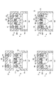
- FIG. 7 is an explanatory view showing a state of fitting of the plug 33 in the cap 3 and the mouth 11 according to the first embodiment of the present invention.
- (a) is a state before the cap 3 and the container body 1 are in contact with each other
- (b) is a state in which the hanging cylindrical wall 32 of the cap 3 has started to contact the peripheral wall 13 of the mouth 11
- (c) is a state.
- the large diameter part 331 of the plug part 33 of the cap 3 pushes the inner wall 141 of the hole part 14 and enters
- (d) shows a state in which the cap 3 and the mouth part 11 are tightly fitted.
- the ceiling wall 31 of the cap 3 is rectangular and the shoulder 19 of the container body 1 is also rectangular and substantially the same size in a top view, and the ceiling wall 31 and the shoulder Since the centers of the caps 19 are substantially equal in the top view, the position of the cap 3 with respect to the mouth 11 can be set almost correctly without checking the back surface of the cap 3.
- the hanging cylindrical wall 32 of the cap 3 starts to contact the peripheral wall 13 of the mouth 11 (FIG. 7B).
- the trajectory when the cap 3 approaches is roughly determined.
- the magnetic force acts so that the magnet 41 of the cap 3 is attracted to the magnet 22 of the mouth portion 11 of the fixed container body 1, and the approach movement of the cap 3 to the mouth portion 11 is promoted.
- the plug 33 of the cap 3 enters the hole 14 of the mouth 11 (FIG. 7 (b) ⁇ FIG. 7 (c)).
- the abutting projection 15 is concaved in a mortar shape (funnel shape) toward the hole portion 14 and protrudes from the upper surface of the upper wall 12 of the mouth portion 11A and is formed in a funnel shape. Even when 3 is inclined, the plug 33 slides along the inclined portion above the abutting projection 15, and the plug 33 is guided to the hole 14.
- the large diameter portion 331 which is the tip end portion and has a large diameter, advances by pushing down the inner wall of the hole portion 14 in the state of FIG. 14I is elastically deformed so as to be crushed to the outer peripheral side.
- FIG. 7C a sealing fit state is obtained (FIG. 7C ⁇ FIG. 7D).
- the large diameter portion 331 at the tip of the plug portion 33 in the state of FIG. 7C is inserted over the narrow inner wall 141 of the hole portion 14 of the mouth portion 11 and then inserted into the plug portion 33.
- the airtightness is achieved in the state shown in FIG. 7D by bringing the shaft portion 332 into close contact with the inner wall 14I.
- magnets having different polarities are magnetically attached to the cap 3 and the mouth 11.
- FIG. 7B When the cap 3 and the container body 1 are brought closer to the position shown in FIG. 7B, an attractive force of the magnet acts. Therefore, by the action of this magnetic force, FIG. 7B ⁇ FIG. 7C ⁇ FIG. ) Is assisted. Accordingly, in the transition from the state of FIG. 7B to the state of FIG. 7C to the state of FIG. 7D, the force of the user to make the sealed state is greatly reduced, and the mounting of the cap 3 is completed. it can.
- FIG. 8 is a top perspective view showing a state in which the cap 3 according to the first embodiment of the present invention is rotated with respect to the mouth 11.
- FIG. 9 is an exploded view of the state of FIG.
- a repulsive force acts between the magnet of the mouth portion 11 and the magnet of the cap 3, and the repulsive force cancels the airtight state by the shaft portion 332 of the plug portion 33 and the inner wall 14 ⁇ / b> I of the hole portion 14.
- the force for the 331 to climb over the hole 14 can be greatly reduced.
- the plug portion 33 has a configuration including the large diameter portion 331 and the shaft portion 332, but the plug portion 33 may have a different shape.
- FIG. 10 is a side sectional view of the cap 3 ⁇ having the stopper 33 ⁇ of the first modification and the mouth 11 of the container body 1.
- the stopper 33 ⁇ is configured by a column 333.
- At least one of the plug 33 ⁇ and the inner wall 141 of the hole 14 is made of a material that is elastically deformed. Therefore, when fitting, the cylinder 333 having a uniform thickness enters in a state of being in close contact with the inner wall 14I and stops in a state of being in close contact, so that airtightness in the fitted state is achieved.
- FIG. 10 an example in which the plug portion 33 ⁇ is formed by the column 333 having a uniform thickness is shown, but the plug portion 33 ⁇ contacts the inner wall 14I of the hole portion 14 in the fitted state, for example, in the cylindrical plug portion.
- One or more portions flange portion, ring portion
- the other outer peripheral portion of the columnar portion does not come into close contact with the inner wall 14I of the hole portion 14, but comes into close contact only with the flange portion. Thereby, at the time of plugging of the plug into the hole 14, the response to the contact with the inner wall 14I at the flange portion changes, and the fitted state can be easily understood.
- FIG. 11 is a side cross-sectional view of the cap 3 ⁇ having the stopper 33 ⁇ of the second modification and the mouth of the container body 1.
- the stopper 33 ⁇ is configured by a downward cone 334.
- the diameter of the plug 33 ⁇ which is the downward cone 334, is gradually increased from the lower end toward the top. Therefore, in the fitting operation, the lower portion having a small diameter enters the inside of the hole portion 14 without making much contact with the inner wall 14I of the hole portion 14, and when the penetration of the plug portion 33 ⁇ reaches an appropriate fitting height, the lower portion is turned downward.
- the thickened portion of the cone 334 and the inner wall 14I of the hole 14 come into contact with each other to be in a fitted state.
- At least one of a portion (at least a part) of the plug portion 33 ⁇ that comes into contact with the inner wall 141I of the hole 14 in the fitted state and at least one of the inner wall 141 of the hole is made of an elastically deformable material. Be composed. Therefore, at the time of fitting, the downward cone 334 and the inner wall 141 come into contact with each other to stop the approach, so that airtightness in the fitted state is achieved.
- FIG. 11 shows an example of a downward conical shape, but the leading end (lower end) may have a flat downward truncated conical shape or a lower conical shape with a rounded lower end.
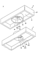
- FIG. 12 is a top perspective view showing a state where the cap 3A and the container body 1A of the second embodiment of the present invention are separated.
- FIG. 13 is a bottom perspective view showing a state where the cap 3A and the container body 1A of the second embodiment are separated.
- FIG. 14 is a cross-sectional perspective view of the cap 3A and the mouth 11A of the container body 1 according to the second embodiment.
- the arrangement position of the magnet in the magnet support band is different from that of the first embodiment.
- a plurality of magnet insertion holes 17A opened downward are formed in the magnet support band 16A of the mouth 11A, and a plurality of magnet insertion holes opened upward are formed in the magnet support band 34A of the cap 3A.
- a hole 35A was formed.
- a plurality of magnet insertion holes 17A that are open upward are formed in the magnet support band 16A of the mouth 11A on the container body 1 side, and are formed in the magnet support band 34A of the cap 3A.
- the upper surfaces of the magnets 23 and 24 are exposed from the opening of the magnet insertion hole 17A in the upper surface of the upper wall 12A in the magnet support band 16A of the mouth 11A of the container body 1A. Then, as shown in FIG. 13, in the magnet support band 34A of the cap 3A, the lower surfaces of the magnets 43 and 44 are exposed on the lower surface (back surface) from the opening of the magnet insertion hole 35A.
- FIG. 15 is a top perspective view of the entire container with the cap 3A closed in the container 5A with a cap according to the second embodiment.
- FIG. 16 is a side sectional view of the cap 3A and the mouth 11A of the container body 1A according to the second embodiment.
- the magnets 23, 24, 43, and 44 are provided on the upper surface of the upper wall 12A of the mouth 11A of the container body 1A and the lower surface of the magnet support band 34A of the cap 3A. Is exposed, the magnets (24, 43) and (23, 44) come into direct contact with each other as shown in FIG. Therefore, it is possible to exert a greater magnetic force than in the first embodiment. Therefore, the size of the magnets (23, 24, 43, 44) can be reduced as compared with the magnets 21, 22, 41, 42 provided in the configuration of FIG.
- the magnets 23 and 24 at the mouth 11A are exposed on the upper surface side of the upper wall 12A and the lower surface of the magnet support band 16A is covered with resin.
- a cover from the lower surface for sealing the openings of the magnets 23 and 24 becomes unnecessary.
- the cap 3A is closed as shown in FIG.
- the magnet is not visible from the external appearance of the cap 3A. Therefore, a cover from the upper surface for sealing the openings of the magnets 43 and 44 to improve the appearance when the cap is closed is not required.
- the shape of the plug portion 33 provided on the cap 3A may be a shape as in the modified example shown in FIGS.
- FIG. 17 is an explanatory diagram showing a state of fitting in each state of the cap 3A and the mouth 11A of the container body 1A according to the second embodiment.
- (a) shows a state before the cap 3A and the mouth 11A come into contact with each other
- (b) shows a state in which the hanging cylindrical wall 32 of the cap 3A has started contact with the peripheral wall 13 of the mouth 11A
- (c) shows a cap.
- (d) shows that the cap 3A and the mouth portion 11A are tightly fitted. Indicates the status.
- the outer shape of the ceiling wall 31A of the cap 3A and the outer shape of the shoulder portion 19 of the container main body 1A are brought closer so as to match (FIG. 17 (a) ⁇ FIG. 17). (B)).
- the inner peripheral surface 32I of the hanging cylindrical wall 32 of the cap 3A starts to contact the outer peripheral surface 130 of the peripheral wall 13 of the mouth 11A (FIG. 17B).
- the magnetic force acts so that the magnet 43 of the cap 3A is attracted to the magnet 24 of the mouth 11A of the fixed container body 1A, thereby promoting the approach movement of the cap 3A to the mouth 11A.
- FIG. 17 (b) ⁇ FIG. 17 (c) ⁇ FIG. 17 (d) shows that the user's force for sealing is greatly reduced, and the cap 3A is not rotated without rotating the cap 3A. Attachment to the container body 1A can be completed.
- the cap 3A when detaching the cap 3A, the cap 3A is rotated in order to release the action of the attractive force by the magnet and to exert a repulsive force.
- FIG. 18 is an exploded view of a state where the cap 3A according to the second embodiment of the present invention is rotated with respect to the mouth 11A.
- the opposing magnets are covered with the resin in both the mouth and the cap.
- the cap is opened.
- the configuration in which the facing magnet is exposed in both the mouth and the cap is shown, but different pairs of the magnet cover and the exposed configuration may be engaged.
- the container body 1 in which the upper surfaces of the magnets 21 and 22 of the mouth 11 are covered with the resin and the cap 3A in which the lower surfaces of the magnets 43 and 44 are exposed are engaged. It may be.
- the container body 1A in which the upper surfaces of the magnets 23 and 24 of the mouth 11A are exposed and the cap 3 in which the lower surfaces of the magnets 41 and 42 are covered with resin are engaged. It may be.
Landscapes
- Engineering & Computer Science (AREA)
- Mechanical Engineering (AREA)
- Closures For Containers (AREA)
Abstract
本発明は、容器本体(1)と、該容器の口部(11)の外周に着脱可能に係合するキャップ(3)とを備えるキャップ付き容器(5)であって、前記口部(11)には、上下に貫通する孔部(14)が形成されており、前記キャップ(3)には、前記孔部(14)に密閉嵌合する、天井壁から下方向に延伸する突起状の栓部(33)が形成され、前記口部(11)及び前記キャップ3のそれぞれに、前記口部(11)と前記キャップ(3)との間で、磁気的な力を発生させる磁石(21,22,42,41)を設けた、キャップ付き容器(5)である。
Description
本発明は、磁力を用いたキャップ付き容器に関する。
容器とキャップとの係合構造として、不用意にキャップが外れることを防いだり、より軽い力で容易にキャップを着脱するため、磁力を用いることが知られている。
例えば、特許文献1には、全覆蓋時におけるキャップと容器本体との当接部位全周に、それぞれ互いに異なる磁極が対向するようにして磁石を配設し、磁石同士が磁着することによってキャップを容器本体に対する覆蓋姿勢に維持する構成が示されている(特許文献1)。
しかし、特許文献1の構成では、キャップの係合の力が磁力による磁着のみであるため、持ち運び、振る、落とす等の外力により、簡単にキャップが外れてしまうことがあった。
そこで、特許文献2には、磁着による構成に加えて、段差を設けることで、キャップを外れにくくする構成が開示されている。
しかし、特許文献2の構成では、口紅等の固体又は半固体の内容物の収容することを前提とした容器であり、内容物を密閉していないため、液体を収容することは想定されていない。そのため、仮にこの構成の容器に内容物として液体を収容すると、容器とキャップとで閉鎖状態を維持していても、傾けたり、逆さまにしたりすると、液体が漏れてしまうおそれがある。
そこで、本発明は上記事情に鑑み、簡単にキャップを着脱できるとともに、キャップ装着状態でのキャップと容器との密封を実現できる、キャップ付き容器の提供を目的とする。
上記課題を解決するため、本発明の一態様では、
容器と、該容器の口部の外周に着脱可能に係合するキャップとを備えるキャップ付き容器であって、
前記口部には、上下に貫通する孔部が形成されており、
前記キャップには、前記孔部に密閉嵌合する、天井壁から下方向に延伸する突起状の栓部が形成され、
前記口部及び前記キャップのそれぞれに、前記口部と前記キャップとの間で、磁気的な力を発生させる磁石を設けた、
キャップ付き容器、を提供する。
容器と、該容器の口部の外周に着脱可能に係合するキャップとを備えるキャップ付き容器であって、
前記口部には、上下に貫通する孔部が形成されており、
前記キャップには、前記孔部に密閉嵌合する、天井壁から下方向に延伸する突起状の栓部が形成され、
前記口部及び前記キャップのそれぞれに、前記口部と前記キャップとの間で、磁気的な力を発生させる磁石を設けた、
キャップ付き容器、を提供する。
一態様によれば、キャップ付き容器において、簡単にキャップを着脱できるとともに、キャップ装着状態でのキャップと容器との密封を実現できる。
以下、図面を参照して本発明を実施するための形態について説明する。下記、各図面において、同一構成部分には同一符号を付し、重複した説明を省略する場合がある。
本発明は、磁力を用いたキャップ付き容器に関する。本発明のキャップ付き容器には、例えば、化粧料(基礎化粧料、ベースメイク用化粧料、ポイントメイク用化粧料)、洗顔料、整髪料、香水等の化粧品や、調味料等の各種液体や粉体が収容される。また、キャップによる密閉が可能であるため、揮発成分を含む物質(液体や粉体)を収容することもできる。
<第1実施形態>
まず、図1~図3を用いて、本発明の第1実施形態のキャップ付き容器5における、容器本体1とキャップ3との係合構造の概略について説明する。
まず、図1~図3を用いて、本発明の第1実施形態のキャップ付き容器5における、容器本体1とキャップ3との係合構造の概略について説明する。
図1は、本発明の第1実施形態のキャップ3と容器本体1が離れた状態を示す上面斜視図である。図2は、第1実施形態のキャップ3と容器本体1が離れた状態を示す下面斜視図である。図3は、第1実施形態のキャップ3と容器本体1の口部の断面斜視図である。
本発明の実施形態に係るキャップ付き容器(蓋付き容器)5は、容器本体1とキャップ(蓋)3とを有する。
容器本体1は、液体や粉体を収容可能な容器である。容器本体1は、肩部19から上方に突出する口部11が設けられている。図1~図3では、容器本体1の上部側である、口部11及び肩部19を示しているが、肩部19の下側には、胴部である収容部10が延伸している(図5参照)。口部11は、上面を有する円筒形状であって、上面の上壁12と側面である周壁13とを有する。
口部11の上壁12の中央部には、上下方向に貫通する孔部14が形成されている。孔部14周囲は、孔部14に向かってすり鉢状(漏斗状)に凹み、上壁12において環状に上方に隆起している、突き当て突起15が形成されている。
また、図2、図3に示すように、上壁12の周端の内周側には、リング状の磁石支持帯16が設けられている。磁石支持帯16は、上壁12の他の部分よりも厚さが分厚い。磁石支持帯16には、下方に開口した複数の磁石挿入穴17が形成されている。上壁12の下面には、さらに、環状リブ18が設けられている。
キャップ3は、容器本体1の口部11に密閉嵌合可能に着脱する。キャップ3の外側面は、天井壁31と外側壁37とで構成されている。キャップ3は、天井壁31の下面から円環状に下方に垂下する垂下筒状壁32が設けられている。キャップ3は、二重側壁の構造を有しており、外側が外側壁37、内側が垂下筒状壁32である。
キャップ3において、垂下筒状壁32の中心には、突起状の栓部(ボス、密封突起、シール部ともいう)33が天井壁31の下面から下向きに突出するように設けられている。栓部33は、口部11の嵌合孔である孔部14に挿入可能である。栓部33は、先端部に位置する大径部331と、小径部である軸部332を有しており、大径部331は軸部332よりも径が大きいことで、孔部14に挿入した際の抜け止めとなる。この栓部33の形状により、栓部33が孔部14に挿入した際に、打栓構造となり、キャップ3が容器本体1を密封して嵌合する。
また、図1、図3に示すように、キャップ3の垂下筒状壁32の内周側には、リング状の磁石支持帯34が設けられている。磁石支持帯34は、天井壁31の他の部分よりも厚さが分厚い。磁石支持帯34には、天井壁31の上面に上方に開口する複数の磁石挿入穴35が形成されている。なお、図3では、口部11及びキャップ3において磁石を除いた状態を示している。
また、天井壁31において、栓部33と、磁石支持帯34とに挟まれる下面は、突き当て突起15と突き当たる突き当て面36となっている。
図4は、本発明のキャップ3及び容器本体1の口部11に設けられる磁石の磁極を示す図である。
本発明の係合構造では、口部11及びキャップ3のそれぞれに、口部11とキャップ3との間で、磁気的な力を発生させる磁石を設けている。
詳しくは、上述のように容器本体1の口部11の上壁12の周端の内周に、円環状の磁石支持帯16が設けられている。そして、キャップ3の垂下筒状壁32の内周側であって、口部11の磁石支持帯16と対向するように、円環状の磁石支持帯34が設けられている。
口部11及びキャップ3のそれぞれの磁石は、円環状の磁石支持帯16,34において、円周状に等間隔で配置された複数の同極部(21,41)と、複数の同極部の間に設けられた複数の他極部(22,42)で形成されている。
詳しくは、図4に示すように、口部11においてN極磁石21とS極磁石22とが交互に配置され、キャップ3においてN極磁石41とS極磁石42が交互に配置されている。そして、口部11に対してキャップ3を閉鎖した状態では、図4に示すように、異極同士の磁石が磁着する。
また、図4に示す例では、磁石は45度毎に設けられているため、磁着した状態から45度回転させると、対向する同極の磁石、即ちN極磁石同士21,41、S極磁石同士22,42により斥力が働く。
このように、引力を働かせる異極と、斥力を働かせる同極の2種類の磁石を同じ面に配置する必要があるため、最小限、2つの磁石を、口部11、キャップ3のそれぞれにおいて設ける。
また、密着状態を解除するための回転動作において、引力が働く異極が対向する位置から、斥力が働く同極が対向する位置まで、回転させるため、その際の回転量を少なくするように、より多くの磁石が配置されていると好適である。図4では、口部11、キャップ3において、45度毎に、8つの磁石を配置している例を示しているが、磁石の数は、8つに限られない。なお、口部11とキャップ3のそれぞれにおいて、引力と斥力を交互に働かせるため、異極の磁石が隣り合うように、1つの面における磁石の数は偶数とする。
図5は、第1実施形態のキャップ付き容器5においてキャップ3と容器本体1が閉じた状態を示す上面斜視図である。
図1~図3で示していた容器本体1は容器本体1の上部側の肩部19と口部11であるが、肩部19の下側には、図5に示すように、液体を収容する、有底角筒状の胴部(ボトル部)である収容部10が設けられている。本実施形態では、容器本体1の肩部19の外形と、キャップ3の天井壁31の外形が略等しいため、キャップが閉じた状態では、キャップ3の側面と、容器本体1の側面とが、同一面状に重なっている。
ここで、図5で示すように、キャップ3と容器本体1の口部11それぞれにおいて、磁石が45度毎に離れて円環状に配置されているため、外形により、引力が働いている状態と斥力が働いている状態が区別できると好適である。そのため、キャップ3の天井壁31は、上面視で正円ではなく、45度回転したことが判別できる形状、例えば、長方形、正方形、ひし形を含む四角形、又は楕円形であると好適である。なお、四角形において、角に丸みが帯びていてもよい。
図5では、キャップ3において、外側壁37と連接する、天井壁31は上面視で略長方形である例を示している。なお、本例では、容器本体1の上面視の外形も略長方形である例を示しているが、容器本体1の肩部19の外形は、キャップ3の形状と異なる形状や大きさであってもよい。ただし、キャップ3を閉める際の、口部11に対するキャップ3の位置を分かりやすくするため、上面視における、肩部19の中心は、キャップ3の天井壁31の中心と一致するような形状にすると好適である。
また、図5では収容部10は略直方体形状の例を示しているが、容器本体1において、口部11がキャップ3と係合可能な形状であり、収容部10において底を有していれば、どのような形状でもよい。例えば、収容部10の底部(下面)が肩部19(上面)に対して徐々に広がったり、狭まっていてもよいし、あるいは、収容部10は、側面が捩じれていたり、胴部の中央が膨らんでいたり、窪んでいたり等、様々な形状であってもよい。
次に、図6、図7を用いて、断面と機能について説明する。図6は、第1実施形態のキャップ3及び容器本体1の口部11の図5の断面Aの縦断面図である。
上述のように、容器本体1の口部11の上壁12には、孔部14が形成され、突き当て突起15、環状リブ18、及び磁石支持帯16が設けられている。
また、図6に示す、図5の断面Aの部分では、垂下筒状壁32が、最も角状の外側壁37に近づいている縦断面であるため、この領域では、キャップ3における二重側壁である、垂下筒状壁32の外側と、外側壁37の内側とが一体化している。
キャップ3の垂下筒状壁32の内周側には、栓部33、磁石支持帯34、突き当て面36が設けられている。
図6に示すように、キャップ3の栓部33の先端は、他の部分である軸部332よりも径が大きい大径部331になっている。口部11の孔部14の内壁14Iの径は、栓部33の軸部332よりも広く、大径部331よりも狭く構成されている。
なお、図6では、大径部331が、栓部33の先端(下端)に設けられた例を示しているが、大径部331は、栓部33の上端から孔部14の厚みまでの部分以外の中間部に設けられてもよい。例えば、図6の図において、大径部331の下にさらに軸部332が延伸していてもよい。あるいは、栓部33の上下方向において、すべての部分が、孔部14の内壁14Iよりも径の大きい大径部331であってもよい。
また、孔部14の内壁14Iは弾性変形する素材で構成されている。そのため、挿入する際や、引き抜く際は、内壁14Iが弾性変形することで、栓部33の先端である大径部331が孔部14を押し分けて通る。
なお、図6では、口部11の内壁14Iが、弾性変形する例を示しているが、内壁14Iに代えて、栓部33の大径部331の外形が弾性変形する構成であってもよい。あるいは、内壁14I及び大径部331の両方が、弾性変形する構成であってもよい。
そのため、大径部331の外周は、弾性変形していない状態の孔部14の内壁14Iよりも径が大きいので、嵌合状態では大径部331が孔部14を押し分ける力が掛からない限りキャップ3と口部11とは密閉状態は解除されないため、傾けたり、逆さまにしたり、振ったりしても、内容物は漏れない。また、口部11の周壁13の外周を取り囲むように、垂下筒状壁32が係合するため、横方向にずれにくい。
また、口部11の磁石支持帯16は、上壁12の上面と上面が略同一平面状であって、上壁の下面側が厚く形成されている。
本実施形態において、口部11の磁石21,22は、磁石支持帯16の下面に下方に開口した複数の磁石挿入穴17に、下から挿入される。そのため、図6に示すように、容器本体1の口部11の磁石支持帯16において、上壁12の上面において、磁石22(21)の上には樹脂の膜が形成されているため、即ち、磁石支持帯16の磁石挿入穴17は上下に連通せずに樹脂が上部に残っているため、磁石22(21)の上面は、樹脂でカバーされている。
また、キャップ3の磁石支持帯34は、天井壁31の上面と、上面が略同一平面状であって、天井壁31の下面側に厚く形成されている。
また、本実施形態において、キャップ3の磁石41,42は上方に開口した、複数の磁石挿入穴35に、上から挿入されている。そのため、磁石41(42)の下には樹脂の膜が形成されており、即ち、磁石支持帯34の磁石挿入穴35は上下に連通せずに樹脂が下部に残っているため、キャップ3の磁石支持帯34の下面において、磁石41(42)の下面は樹脂でカバーされている。
このように、本実施形態では、口部11及びキャップ3ともに、キャップ3を開放した状態で使用者に見える部分が、磁石(22(21)、41(42))が樹脂によってカバーされているため、使用時の口部11及びキャップ3の裏面の美観を保つことができる。
なお、図6では、容器本体1側の磁石支持帯16の磁石挿入穴17の下方が開口し、キャップ3側の磁石支持帯34の磁石挿入穴35の上方が開口しているが、磁石を挿入した後、樹脂やシール等で磁石挿入穴17,35を封止すると、より好適である。
詳しくは、容器本体1の口部11の磁石支持帯16では、下面が開口しているため、挿入される磁石21,22と、収容物の液体とが接触する可能性がある。そのため、磁石21,22が、内容物の液体により劣化したり、反対に液体内に、磁石の成分である、例えば、アルニコ、フェライト、ネオジム、サマリウムコバルト等が、流れ出てしまうおそれがあるため、液体の品質維持、及び安全面の観点から、磁石21,22を下面からカバーすると、より好適である。
一方、キャップ3の磁石支持帯34において、上面が開口した磁石挿入穴35を磁石41,42挿入後に、樹脂で封止することで、キャップ3の表面及び裏面の両方から磁石を使用者に隠して美観を高める観点から、磁石41,42を上面から樹脂やシール等でカバーすると、より好適である。
また、環状リブ18は、口部11の上壁12の下面であって、孔部14の外側であって、磁石支持帯16の内周側に、下方に起立している。この環状リブ18は、磁石支持帯16よりも下側に突出している。
そのため、例えば、キャップ付き容器5を振ったり、落としたり、倒したり等で内部に収容された液体から、肩部19の下面や、上壁12の下面に強い力が掛かりそうな場合は、口部11の周壁13の内周側では、まず環状リブ18に力が掛かる。そのため、孔部14や、磁石支持帯16にかかる、液体からの力は緩和されるため、例えば、上方向に強い力が掛かった際にも、キャップ3を回転させない限り、磁気力として、対向する異極の磁石間に引力が作用しているので、栓部33と孔部14との嵌合状態は解除されず、栓部33は抜けない。また、磁石支持帯16への力も弱まるため、磁石も壊れない。なお、環状リブ18は、力が掛かることを考慮して、弾性部材で構成されると好適である。
図6に示す例では、キャップ3の磁石21以外の部分、容器本体1の磁石支持帯16の磁石42以外の部分、口部11の周壁13、肩部19及び収容部10を、樹脂で構成される例を示しているが、他の素材で構成してもよい。例えばこれらの部分を、強化ガラス等で構成してもよい。
図7は、本発明の第1実施形態のキャップ3及び口部11における栓部33の嵌合の様子を示す説明図である。図7において、(a)はキャップ3と容器本体1とが接触前、(b)はキャップ3の垂下筒状壁32が、口部11の周壁13と接触を開始した状態、(c)はキャップ3の栓部33の大径部331が孔部14の内壁14Iを押し広げて進入している状態、(d)はキャップ3と口部11とが密閉嵌合している状態を示す。
キャップ3を容器本体1に係合する際、まず、キャップ3の天井壁31の外形と容器本体1の肩部19の外形とが、重なるように近づけていく(図7(a)⇒図7(b))。この際、本構成では、上面視で、キャップ3の天井壁31が長方形であって、容器本体1の肩部19も長方形であって略等しい大きさであり、且つ、天井壁31と肩部19の中心が上面視で略等しいため、キャップ3の裏面を確認しなくても、口部11に対するキャップ3の位置を、ほぼ正しくセットすることができる。
そして、この図7(a)~図7(d)の装着動作の際、図7(a)でのキャップ3と肩部19との外形を用いた、キャップ3の向きを容器本体1に対して正しくセットした後は、キャップ3を、容器本体1に対して回転させる必要はない。
そして、最初の接触として、キャップ3の垂下筒状壁32が、口部11の周壁13と接触を開始する(図7(b))。垂下筒状壁32の内周面32Iと、周壁13の外周面13Oとが接触を開始することで、キャップ3を近づける際の軌道が、大体定められる。
この状態で、キャップ3の磁石41が、固定された容器本体1の口部11の磁石22に引き寄せられるように磁力が働くことで、キャップ3の口部11への接近移動が促される。さらにキャップ3が容器本体1に近づくと、キャップ3の栓部33が、口部11の孔部14へと進入する(図7(b)⇒図7(c))。なお、この際、突き当て突起15は、孔部14に向かってすり鉢状(漏斗状)に凹み、口部11Aの上壁12の上面から隆起して漏斗状に形成されているため、例えばキャップ3が傾いている場合であっても、突き当て突起15の上側の傾斜部に沿って、栓部33がスライドすることで、栓部33は、孔部14に導かれる。
なお、本例では、孔部14の周囲は、突き当て突起15として口部11の上壁12の上面に対して隆起する例を説明したが、例えば、口部11の上壁12が分厚い場合、上壁12の厚さの内部で、上面から下部に細くなる漏斗状の凹部を形成して、その凹部の下に孔部が貫通している形状であって、隆起を有しない形状であってもよい。この形状においても、漏斗状の凹部(上孔部)の傾斜により、下孔部である孔部14に栓部33を導くことができる。
また、図7(c)の状態では、栓部33は、先端部であって径が大きい大径部331が、孔部14の内壁を押し分けて進んでいるため、孔部14の側面の内壁14Iは外周側に潰れるように弾性変形している。
その後、キャップ3が、口部11に対してさらに接近することで、密封嵌合状態となる(図7(c)⇒図7(d))。キャップ3を係合する際、図7(c)の状態の栓部33の先端の大径部331が、口部11の孔部14の狭い内壁14Iを乗り越えて挿入された後、栓部33の軸部332が内壁14Iと密着することで、図7(d)の状態では、気密が達成される。図7(d)では、図4に示したように、キャップ3と口部11において、異極の磁石同士が磁着している。
なお、図7(b)の位置にキャップ3と容器本体1とを近づけると、磁石の引力が作用するので、この磁力の働きにより図7(b)⇒図7(c)⇒図7(d)の閉鎖動作が補助される。これにより、図7(b)⇒図7(c)⇒図7(d)の状態の移行では、使用者の、密封状態にするための力は大幅に軽減されて、キャップ3の装着を終了できる。
反対に、キャップ3を脱着する際には、キャップ3と口部11とを密着させる方向にかかる引力の作用を解除し、キャップ3と口部11とを離間させる方向にかかる斥力を働かせるために、容器本体1に対してキャップ3を回転させる。
図8は、本発明の第1実施形態のキャップ3を、口部11に対して回転させた状態を示す上面斜視図である。図9は、図8の状態の分解図である。
図8、図9のように、キャップ3を閉じた状態から45度回転させることで、キャップ3の磁石41,42と、口部11の磁石21,22の、同極同士が対向する。
これにより、口部11の磁石と、キャップ3の磁石との間で斥力を作用させ、斥力により、栓部33の軸部332と孔部14の内壁14Iによる気密状態を解除し、大径部331が孔部14を乗り越えて上昇するための力を大幅に軽減できる。
<栓部の変形例>
上記例では、栓部33は、大径部331と軸部332を備えている構成を示しているが、栓部33は、異なる形状であってもよい。
上記例では、栓部33は、大径部331と軸部332を備えている構成を示しているが、栓部33は、異なる形状であってもよい。
図10に、第1の変形例の栓部33αを有するキャップ3α及び容器本体1の口部11の側面断面図を示す。図10に示すように、本変形例のキャップ付き容器5αでは、栓部33αは、円柱333で構成されている。
本変形例においても、栓部33α、又は孔部14の内壁14Iの、少なくともどちらか一方は弾性変形する素材で構成される。そのため、嵌合する際、一律の太さの円柱333は内壁14Iに密着した状態で進入し、密着状態で停止するため、嵌合状態における気密が達成される。
なお、図10では、一律の太さの円柱333によって、栓部33αを構成する例を示したが、円柱状の栓部に、例えば、嵌合状態において、孔部14の内壁14Iと接触する部分に、少し径が太い部分(フランジ部、リング部)を1又は複数設けてもよい。フランジ部を設けることで、円柱部の他の外周部が孔部14の内壁14Iと密着せず、フランジ部のみで密着する。これにより、栓部の孔部14内への打栓の際、フランジ部の部分で、内壁14Iとの接触の手ごたえが変化して嵌合状態がわかりやすくなる。
図11に、第2の変形例の栓部33βを有するキャップ3β及び容器本体1の口部の側面断面図を示す。図11に示すように、本変形例のキャップ付き容器5βでは、栓部33βは、下向き円錐334で構成されている。
下向き円錐334である栓部33βは、下端から上に行くほど徐々に径が太くなっている。そのため、嵌合動作において、径が細い下部分では孔部14の内壁14Iとほとんど接触せずに孔部14の内部に進入し、栓部33βの進入が適切な嵌合高さまで到達すると、下向き円錐334の径が太くなった部分と、孔部14の内壁14Iとが接触して、嵌合状態になる。
なお、本変形例では、栓部33βにおける、嵌合状態において孔部14の内壁141Iと接触する部分(少なくとも一部)と、孔部の内壁14Iの少なくともどちらか一方は、弾性変形する素材で構成される。そのため、嵌合する際、下向き円錐334と内壁141とは、密着状態になることで進入を停止するため、嵌合状態における気密が達成される。
なお、図11では、下向き円錐形状の例を示しているが、先頭部(下端部)が、平面状の下向き円錐台形状、または下端部が丸みを帯びた下向き円錐形状であってもよい。
<第2実施形態>
次に、図12~図18を用いて、第2実施形態のキャップ付き容器5Aの構成について説明する。
次に、図12~図18を用いて、第2実施形態のキャップ付き容器5Aの構成について説明する。
図12は、本発明の第2実施形態のキャップ3Aと容器本体1Aが離れた状態を示す上面斜視図である。図13は、第2実施形態のキャップ3Aと容器本体1Aが離れた状態を示す下面斜視図である。図14は、第2実施形態のキャップ3Aと容器本体1の口部11Aの断面斜視図である。
本実施形態では、磁石支持帯での磁石の配置位置が、第1実施形態とは異なる。第1実施形態では、口部11Aの磁石支持帯16Aには、下方に開口した複数の磁石挿入穴17Aが形成されており、キャップ3Aの磁石支持帯34Aには上方に開口した複数の磁石挿入穴35Aが形成されていた。
これに対して、本実施形態では、容器本体1側の口部11Aの磁石支持帯16Aには、上方に開口した複数の磁石挿入穴17Aが形成されており、キャップ3Aの磁石支持帯34Aには下方に開口した複数の磁石挿入穴35Aが形成されている。
そのため、図12に示すように、容器本体1Aの口部11Aの磁石支持帯16Aにおいて、上壁12Aの上面において、磁石挿入穴17Aの開口部から磁石23,24の上面は露出している。そして、図13に示すように、キャップ3Aの磁石支持帯34Aにおいて、磁石挿入穴35Aの開口部から下面(裏面)に磁石43,44の下面は露出している。
図15は、第2実施形態のキャップ付き容器5Aにおいてキャップ3Aが閉じた状態を示す容器全体の上面斜視図である。図16は、第2実施形態のキャップ3A及び容器本体1Aの口部11Aの側面断面図である。
本実施形態では、図13、図14で示したように、容器本体1Aの口部11Aの上壁12Aの上面、及びキャップ3Aの磁石支持帯34Aの下面に、磁石23,24、43,44は露出しているため、図16に示すように、磁石(24,43),(23,44)同士が直接接触する。そのため、第1実施形態よりも磁力の力を大きく働かせることができる。そのため、図6の構成で設けられる磁石21,22,41,42と比較して、磁石(23,24,43,44)自体の大きさを小さくすることができる。
なお、本実施形態では、口部11Aにおいて磁石23,24が上壁12Aの上面側が露出し、磁石支持帯16Aの下面は樹脂でカバーされているため、液体の品質維持や安全面を考慮した、磁石23,24の開口部の封止のための下面からのカバーは不要になる。
また、本実施形態では、キャップ3Aにおいて磁石43,44が磁石支持帯34Aの下面側に露出し、天井壁31Aの上面は樹脂でカバーされているため、図15のようにキャップ3Aを閉じている際は、キャップ3Aの外観からの磁石は見えない。そのため、キャップを閉じている際の美観を向上するための、磁石43,44の開口部の封止のための上面からのカバーは不要になる。
なお、本実施形態においても、キャップ3Aに設けられる栓部33の形状を、図10、図11に示す変形例のような形状としてもよい。
図17は、第2実施形態のキャップ3A及び容器本体1Aの口部11Aの各状態における嵌合の様子を示す説明図である。図17において、(a)はキャップ3Aと口部11Aとが接触前、(b)はキャップ3Aの垂下筒状壁32が口部11Aの周壁13と接触を開始した状態、(c)はキャップ3Aの栓部33の大径部331が口部11Aの孔部14の内壁14Iを押し広げて進入している状態、(d)は、キャップ3Aと口部11Aとが密閉嵌合している状態を示す。
キャップ3Aを容器本体1Aに係合する際、まず、キャップ3Aの天井壁31Aの外形と容器本体1Aの肩部19の外形とを合致させるように近づけていく(図17(a)⇒図17(b))。これにより、キャップ3Aの垂下筒状壁32の内周面32Iが、口部11Aの周壁13の外周面13Oと接触を開始する(図17(b))。この際、キャップ3Aの磁石43が、固定された容器本体1Aの口部11Aの磁石24に引き寄せられるように磁力が働くことで、キャップ3Aの口部11Aへの接近移動が促される。
さらにキャップ3Aが容器本体1Aに近づくと、キャップ3Aの栓部33が、口部11Aの孔部14へと進入する。栓部33は、漏斗状の突き当て突起15によって孔部14に導かれる。また、図17(c)の状態では、栓部33の大径部331によって、孔部14の内壁14Iは外周側に潰れるように弾性変形している。
その後、キャップ3Aは、口部11Aに対してさらに接近することで、密封嵌合状態となる(図17(c)⇒図17(d))。キャップ3Aを係合する際、図17(c)の状態の栓部33の先端の大径部331が、口部11Aの孔部14の狭い内壁14Iを乗り越えて挿入されることで、図17(d)の状態では、打栓により栓部33の軸部332が内壁14Iと密着することで、気密が達成される。
なお、本実施形態においても、図17(b)の位置に磁石を近づけると、磁力の働きにより、図17(b)⇒図17(c)⇒図17(d)の閉鎖動作が補助される。そのため、図17(b)⇒図17(c)⇒図17(d)は、使用者の、密封状態にするための力は大幅に軽減されて、キャップ3Aを回転させることなく、キャップ3Aの容器本体1Aへの装着を終了できる。
逆に、キャップ3Aを脱着する際に、磁石による引力の作用を解除し、斥力を働かせるために、キャップ3Aを回転させる。
図18は、本発明の第2実施形態のキャップ3Aを、口部11Aに対して回転させた状態の分解図である。
図18のように、キャップ3Aを閉じた状態から45度回転させることで、キャップ3Aの磁石43,44と、口部11Aの磁石23,24の、同極同士が対向する。
これにより、口部11Aの磁石23,24と、キャップ3Aの磁石43,44との間で斥力を作用させて、栓部33の軸部332と孔部14の内壁14Iによる気密状態を解除し、大径部331が孔部14を乗り越えて上昇するための力を大幅に軽減できる。
なお、上述において、第1実施形態では、キャップを空けた際に、口部及びキャップの両方において、対向する磁石が樹脂によってカバーされている構成であり、第2実施形態では、キャップを空けた際に、口部及びキャップの両方において、対向する磁石が露出している構成を示しているが、磁石のカバーと露出の構成について異なるペアを係合させてもよい。
例えば、キャップを空けた際に、口部11の磁石21,22の上面が樹脂によってカバーされている容器本体1と、磁石43,44の下面が露出しているキャップ3Aとを係合させる構成であってもよい。あるいは、キャップを空けた際に、口部11Aの磁石23,24の上面が露出している容器本体1Aと、磁石41,42の下面が樹脂によってカバーされているキャップ3とを係合させる構成であってもよい。
以上、本発明の好ましい実施形態について詳述したが、本発明は係る特定の実施形態に限定されるものではなく、特許請求の範囲に記載された本発明の実施形態の要旨の範囲内において、種々の変形、変更が可能である。
本出願は、2018年9月3日に日本国特許庁に出願された特願2018-164858号に基づく優先権を主張するものであり、特願2018-164858号の全内容を本出願に援用する。
1,1A 容器本体
3,3A,3α,3β キャップ
5,5A,5α,5β キャップ付き容器
10 収容部
11,11A 口部
12,12A 上壁
13 周壁
14 孔部
15 突き当て突起
16,16A 磁石支持帯
17,17A 磁石挿入穴
18 環状リブ
19 肩部
21,23 磁石(N極)
22,24 磁石(S極)
31,31A 天井壁
32 垂下筒状壁
33,33α,33β 栓部
331 大径部
332 軸部(小径部)
333 円柱
334 下向き円錐
34,34A 磁石支持帯
35,35A 磁石挿入穴
36 突き当て面
37 外側壁
41,43 磁石(N極)
42,44 磁石(S極)
5,5A キャップ付き容器
Claims (17)
- 容器と、該容器の口部の外周に着脱可能に係合するキャップとを備えるキャップ付き容器であって、
前記口部には、上下に貫通する孔部が形成されており、
前記キャップには、前記孔部に密閉嵌合する、天井壁から下方向に延伸する突起状の栓部が形成され、
前記口部及び前記キャップのそれぞれに、前記口部と前記キャップとの間で、磁気的な力を発生させる磁石を設けた
キャップ付き容器。 - 前記栓部の少なくとも一部、又は前記孔部の内壁の、少なくともどちらか一方は弾性変形する素材で構成される
請求項1に記載のキャップ付き容器。 - 前記キャップの前記栓部は、嵌合状態において、前記孔部よりも下側になる位置に、前記孔部の内壁の径よりも径が大きい大径部を有している
請求項2に記載のキャップ付き容器。 - 前記キャップの前記栓部は、前記大径部よりも上側に前記大径部よりも径が小さい小径部を有している
請求項3に記載のキャップ付き容器。 - 嵌合状態において、前記キャップの前記栓部の少なくとも一部は、前記孔部の前記内壁の少なくとも一部と、密着している
請求項2に記載のキャップ付き容器。 - 前記口部の周囲は、前記孔部に向かってすり鉢状に凹むように傾斜している
請求項2に記載のキャップ付き容器。 - 前記すり鉢状の傾斜部は、前記孔部を取り囲むように、前記口部の上壁の上面から隆起している突き当て突起である
請求項6に記載のキャップ付き容器。 - 前記キャップは、前記口部の外周と接触するように、前記天井壁から下方に垂下し、前記栓部を中心とする垂下筒状壁が設けられている
請求項1に記載のキャップ付き容器。 - 前記口部の上壁の周端の内周に、円環状の磁石支持帯が設けられており、
前記キャップに、前記口部の磁石支持帯と対向するように、円環状の磁石支持帯が設けられている
請求項1に記載のキャップ付き容器。 - 前記口部及び前記キャップのそれぞれの前記磁石は、前記磁石支持帯において、円周状に等間隔で配置された複数の同極部と、複数の同極部の間に設けられた複数の他極部で形成されている
請求項9に記載のキャップ付き容器。 - 前記キャップを前記口部に対して回転させることで、前記口部の磁石と、前記キャップの磁石との間で斥力を作用させる
請求項9に記載のキャップ付き容器。 - 前記容器の前記口部の前記磁石支持帯において、前記上壁の上面に前記磁石は露出している
請求項9に記載のキャップ付き容器。 - 前記容器の前記口部の前記磁石支持帯において、前記上壁の上面において、前記磁石は樹脂でカバーされている
請求項9に記載のキャップ付き容器。 - 前記キャップの前記磁石支持帯の下面に前記磁石は露出している
請求項9に記載のキャップ付き容器。 - 前記キャップの前記磁石支持帯の下面において、前記磁石は樹脂でカバーされている
請求項9に記載のキャップ付き容器。 - 前記口部の前記磁石支持帯は、前記口部の前記上壁と上面が略同一平面状であって、前記上壁の下面側が厚く形成されており、
前記キャップの前記磁石支持帯は、前記天井壁と上面が略同一平面状であって、前記天井壁の下面側に厚く形成されている
請求項9に記載のキャップ付き容器。 - 前記キャップの前記天井壁は上面視で四角形又は楕円形である
請求項1に記載のキャップ付き容器。
Applications Claiming Priority (2)
| Application Number | Priority Date | Filing Date | Title |
|---|---|---|---|
| JP2018164858A JP7184572B2 (ja) | 2018-09-03 | 2018-09-03 | キャップ付き容器 |
| JP2018-164858 | 2018-09-03 |
Publications (1)
| Publication Number | Publication Date |
|---|---|
| WO2020050176A1 true WO2020050176A1 (ja) | 2020-03-12 |
Family
ID=69721650
Family Applications (1)
| Application Number | Title | Priority Date | Filing Date |
|---|---|---|---|
| PCT/JP2019/034197 Ceased WO2020050176A1 (ja) | 2018-09-03 | 2019-08-30 | キャップ付き容器 |
Country Status (3)
| Country | Link |
|---|---|
| JP (1) | JP7184572B2 (ja) |
| TW (1) | TW202019787A (ja) |
| WO (1) | WO2020050176A1 (ja) |
Families Citing this family (1)
| Publication number | Priority date | Publication date | Assignee | Title |
|---|---|---|---|---|
| KR102786171B1 (ko) * | 2022-03-16 | 2025-03-26 | 한빅솔라(주) | 금속 마스크의 화학적 연마장치 |
Citations (8)
| Publication number | Priority date | Publication date | Assignee | Title |
|---|---|---|---|---|
| JPS61188940U (ja) * | 1985-02-07 | 1986-11-25 | ||
| JPS62159348U (ja) * | 1986-03-27 | 1987-10-09 | ||
| JPS62159345U (ja) * | 1986-03-26 | 1987-10-09 | ||
| JPH03100141U (ja) * | 1990-01-29 | 1991-10-18 | ||
| JP2010100325A (ja) * | 2008-10-24 | 2010-05-06 | Katsuhiko Sasaki | 磁石式容器と蓋 |
| US20130330113A1 (en) * | 2012-06-06 | 2013-12-12 | Tair Jluh Enterprise Co., Ltd. | Cosmetic container |
| WO2017138630A1 (ja) * | 2016-02-12 | 2017-08-17 | 株式会社 資生堂 | 化粧料容器 |
| US20170265618A1 (en) * | 2016-03-16 | 2017-09-21 | HCT Group Holdings Limited | Cosmetic container with closure |
-
2018
- 2018-09-03 JP JP2018164858A patent/JP7184572B2/ja not_active Expired - Fee Related
-
2019
- 2019-08-30 WO PCT/JP2019/034197 patent/WO2020050176A1/ja not_active Ceased
- 2019-09-02 TW TW108131526A patent/TW202019787A/zh unknown
Patent Citations (8)
| Publication number | Priority date | Publication date | Assignee | Title |
|---|---|---|---|---|
| JPS61188940U (ja) * | 1985-02-07 | 1986-11-25 | ||
| JPS62159345U (ja) * | 1986-03-26 | 1987-10-09 | ||
| JPS62159348U (ja) * | 1986-03-27 | 1987-10-09 | ||
| JPH03100141U (ja) * | 1990-01-29 | 1991-10-18 | ||
| JP2010100325A (ja) * | 2008-10-24 | 2010-05-06 | Katsuhiko Sasaki | 磁石式容器と蓋 |
| US20130330113A1 (en) * | 2012-06-06 | 2013-12-12 | Tair Jluh Enterprise Co., Ltd. | Cosmetic container |
| WO2017138630A1 (ja) * | 2016-02-12 | 2017-08-17 | 株式会社 資生堂 | 化粧料容器 |
| US20170265618A1 (en) * | 2016-03-16 | 2017-09-21 | HCT Group Holdings Limited | Cosmetic container with closure |
Also Published As
| Publication number | Publication date |
|---|---|
| TW202019787A (zh) | 2020-06-01 |
| JP2020037424A (ja) | 2020-03-12 |
| JP7184572B2 (ja) | 2022-12-06 |
Similar Documents
| Publication | Publication Date | Title |
|---|---|---|
| RU2602743C2 (ru) | Устройство соединения емкости с резервуаром, способ сборки и использования такого устройства | |
| CN100364863C (zh) | 包括可水平旋转封盖的存储容器 | |
| US10206482B2 (en) | Cosmetic container with inner lid | |
| MXPA05002458A (es) | Contenedores sellados y metodos para hacer y llenar los mismos. | |
| JP2017013830A (ja) | ヒンジキャップ | |
| JP2020037424A (ja) | キャップ付き容器 | |
| JP2018140788A (ja) | 詰め替え容器 | |
| JP2018140816A (ja) | キャップ付き内容器 | |
| KR101505789B1 (ko) | 화장품용기 | |
| JP3421792B2 (ja) | 液体化粧料容器 | |
| JP2012254802A (ja) | 薬液容器 | |
| KR200297641Y1 (ko) | 파우더 콤팩트용 리필케이스 구조 | |
| JP2003175971A (ja) | レフィル式ディスペンサー容器 | |
| JP2004026223A (ja) | キャップ | |
| JP3087204U (ja) | 開封キャップ付チューブ容器 | |
| JP4756494B2 (ja) | 着脱蓋体付き容器 | |
| CN107672926A (zh) | 卫生尖嘴盖 | |
| JP2018175360A (ja) | 可動中子を有する広口容器 | |
| CN111556717B (zh) | 用于利用相同部件制造化妆品容器的化妆品容器系统 | |
| CN115158889B (zh) | 包装瓶 | |
| JPH0339418Y2 (ja) | ||
| JP5046108B2 (ja) | 二剤混合容器 | |
| JP7689804B2 (ja) | 二重容器 | |
| JPH076102Y2 (ja) | キャップ付き容器 | |
| CN204863991U (zh) | 组合盖和包装体 |
Legal Events
| Date | Code | Title | Description |
|---|---|---|---|
| 121 | Ep: the epo has been informed by wipo that ep was designated in this application |
Ref document number: 19857558 Country of ref document: EP Kind code of ref document: A1 |
|
| NENP | Non-entry into the national phase |
Ref country code: DE |
|
| 122 | Ep: pct application non-entry in european phase |
Ref document number: 19857558 Country of ref document: EP Kind code of ref document: A1 |