WO2020049923A1 - 画像読取装置及び画像形成装置 - Google Patents
画像読取装置及び画像形成装置 Download PDFInfo
- Publication number
- WO2020049923A1 WO2020049923A1 PCT/JP2019/030502 JP2019030502W WO2020049923A1 WO 2020049923 A1 WO2020049923 A1 WO 2020049923A1 JP 2019030502 W JP2019030502 W JP 2019030502W WO 2020049923 A1 WO2020049923 A1 WO 2020049923A1
- Authority
- WO
- WIPO (PCT)
- Prior art keywords
- image
- image data
- unit
- symbol
- generation unit
- Prior art date
- Legal status (The legal status is an assumption and is not a legal conclusion. Google has not performed a legal analysis and makes no representation as to the accuracy of the status listed.)
- Ceased
Links
Images



Classifications
-
- H—ELECTRICITY
- H04—ELECTRIC COMMUNICATION TECHNIQUE
- H04N—PICTORIAL COMMUNICATION, e.g. TELEVISION
- H04N1/00—Scanning, transmission or reproduction of documents or the like, e.g. facsimile transmission; Details thereof
- H04N1/387—Composing, repositioning or otherwise geometrically modifying originals
- H04N1/3872—Repositioning or masking
- H04N1/3873—Repositioning or masking defined only by a limited number of coordinate points or parameters, e.g. corners, centre; for trimming
-
- H—ELECTRICITY
- H04—ELECTRIC COMMUNICATION TECHNIQUE
- H04N—PICTORIAL COMMUNICATION, e.g. TELEVISION
- H04N1/00—Scanning, transmission or reproduction of documents or the like, e.g. facsimile transmission; Details thereof
- H04N1/0035—User-machine interface; Control console
- H04N1/00405—Output means
- H04N1/00408—Display of information to the user, e.g. menus
- H04N1/0044—Display of information to the user, e.g. menus for image preview or review, e.g. to help the user position a sheet
-
- H—ELECTRICITY
- H04—ELECTRIC COMMUNICATION TECHNIQUE
- H04N—PICTORIAL COMMUNICATION, e.g. TELEVISION
- H04N1/00—Scanning, transmission or reproduction of documents or the like, e.g. facsimile transmission; Details thereof
-
- H—ELECTRICITY
- H04—ELECTRIC COMMUNICATION TECHNIQUE
- H04N—PICTORIAL COMMUNICATION, e.g. TELEVISION
- H04N1/00—Scanning, transmission or reproduction of documents or the like, e.g. facsimile transmission; Details thereof
- H04N1/387—Composing, repositioning or otherwise geometrically modifying originals
- H04N1/3872—Repositioning or masking
- H04N1/3873—Repositioning or masking defined only by a limited number of coordinate points or parameters, e.g. corners, centre; for trimming
- H04N1/3875—Repositioning or masking defined only by a limited number of coordinate points or parameters, e.g. corners, centre; for trimming combined with enlarging or reducing
-
- H—ELECTRICITY
- H04—ELECTRIC COMMUNICATION TECHNIQUE
- H04N—PICTORIAL COMMUNICATION, e.g. TELEVISION
- H04N1/00—Scanning, transmission or reproduction of documents or the like, e.g. facsimile transmission; Details thereof
- H04N1/387—Composing, repositioning or otherwise geometrically modifying originals
- H04N1/3877—Image rotation
Definitions
- the present invention relates to an image reading device and an image forming device.
- an image reading apparatus that collectively reads a plurality of documents placed on a document table and generates respective image data of the plurality of documents. Furthermore, after reading the front side of a plurality of documents at a time, the back side of the plurality of documents is read at a time and the image data on the front side and the image data on the back side are associated with each document. Reading devices are known. Such an image reading apparatus can perform a preview display of the front side image and the back side image collectively for each document.
- the image reading apparatus disclosed in Patent Document 1 has a configuration in which image data of a front surface is read based on each area where each document is placed when reading the front surface and each area where each document is placed when reading the back surface. And the image data of the back side.
- An advantage of some aspects of the invention is to provide an image reading apparatus and an image forming apparatus that can reduce a possibility of incorrectly associating a combination of image data of a front surface and image data of a back surface with the object. It is in.
- the image reading apparatus includes a document table, a first generation unit, a first allocation unit, a second generation unit, a second allocation unit, and an association unit.
- the first generation unit generates a plurality of first image data each indicating an image of a first surface of each of a plurality of documents placed on the document table.
- the first allocating unit allocates different first symbols to each of the plurality of first image data based on a reference position of the platen.
- the second generation unit generates a plurality of second image data each showing an image of a second surface of each of the plurality of documents placed on the document table.
- the second allocating unit allocates different second symbols to each of the plurality of second image data based on the reference position.
- the associating unit associates each of the plurality of first image data with each of the plurality of second image data based on the first symbol and the second symbol.
- the image forming apparatus includes a platen, a first generation unit, a first allocation unit, a second generation unit, a second allocation unit, and an association unit.
- the first generation unit generates a plurality of first image data each indicating an image of a first surface of each of a plurality of documents placed on the document table.
- the first allocating unit allocates different first symbols to each of the plurality of first image data based on a reference position of the platen.
- the second generation unit generates a plurality of second image data each showing an image of a second surface of each of the plurality of documents placed on the document table.
- the second allocating unit allocates different second symbols to each of the plurality of second image data based on the reference position.
- the associating unit associates each of the plurality of first image data with each of the plurality of second image data based on the first symbol and the second symbol.
- the image reading apparatus and the image forming apparatus it is possible to reduce the possibility that the combination of the image data on the front surface and the image data on the back surface is erroneously associated.
- FIG. 1 is a schematic diagram illustrating a configuration of an image forming apparatus according to an embodiment of the present invention.
- FIG. 2 is a block diagram illustrating a configuration of the image forming apparatus. It is a schematic diagram which shows the process of the first half among allocation processes. It is a schematic diagram which shows the latter half process among allocation processes. It is a schematic diagram which shows the aggregated image which aggregated the two images linked
- FIG. 1 is a schematic diagram illustrating a configuration of an image forming apparatus 100 according to an embodiment of the present invention.
- the image forming apparatus 100 is a multifunction peripheral.
- the image forming apparatus 100 has a scanner function, a copy function, and a communication function.
- the image forming apparatus 100 includes an image reading unit 10, a sheet cassette 20, a sheet conveying unit 30, an image forming unit 40, a sheet discharging unit 50, an input / output unit 60, and a communication unit. It comprises a unit 70 and a control unit 80. Note that the image forming apparatus 100 is an example of an image reading apparatus.
- the image reading unit 10 includes a document table 11.
- the document table 11 places a plurality of documents.
- the image reading unit 10 reads a document placed on the document table 11, generates image data, and transmits the image data to the control unit 80. More specifically, the image reading unit 10 collectively reads images on the first surface (for example, the front (front) surface) of a plurality of documents placed on the document table 11, Generate data. Further, the image reading unit 10 collectively reads images on the second surface (for example, the back surface) of a plurality of documents placed on the document table 11 to generate second surface data.
- the image reading unit 10 transmits the first surface data and the second surface data to the control unit 80.
- the image represented by the first plane data is referred to as a first plane image
- the image represented by the second plane data is referred to as a second plane image.
- the paper cassette 20 accommodates the recording medium P for printing.
- the recording medium P in the paper feed cassette 20 is transported by the paper transport unit 30 so as to be discharged from the paper discharge unit 50 via the image forming unit 40.
- the paper transport unit 30 transports the recording medium P to the paper discharge unit 50 via the image forming unit 40.
- the image forming unit 40 forms an image on the recording medium P based on the image data for printing generated by the control unit 80.
- the recording medium P is, for example, paper.
- the input / output unit 60 detects various touch operations by the user of the image forming apparatus 100.
- the input / output unit 60 has a display unit 61 for displaying an image.
- the display unit 61 displays various information to be presented to the user.
- the display unit 61 displays, for example, an aggregated image described later with reference to FIG.
- the input / output unit 60 detects a touch operation on the aggregated image displayed on the display unit 61 and notifies the control unit 80 of an instruction based on the touch operation. Further, the input / output unit 60 displays an image generated by the control unit 80 according to an instruction from the control unit 80.
- the input / output unit 60 is, for example, a liquid crystal display having a touch panel. Note that the input / output unit 60 is an example of a detection unit.
- the communication unit 70 can communicate with an electronic device using the same communication method (protocol).
- the communication unit 70 communicates with an external information processing device (hereinafter, the external information processing device is referred to as an “external device”) via a network such as the Internet and a LAN (Local Area Network).
- the external information processing device is referred to as an “external device”
- the communication unit 70 is, for example, a communication module such as a LAN board.
- the control unit 80 controls the operation of each component of the image forming apparatus 100. Further, the control unit 80 receives the image data generated by the image reading unit 10 and generates image data for printing. Further, the control unit 80 receives the image data generated by the image reading unit 10 and generates image data of an image to be preview-displayed on the display unit 61.
- FIG. 2 is a block diagram illustrating a configuration of the image forming apparatus 100.
- the image forming apparatus 100 includes the image reading unit 10, the image forming unit 40, the input / output unit 60, the communication unit 70, and the control unit 80.
- FIG. 2 shows a detailed configuration of the control unit 80.
- the control unit 80 includes a processing unit 81 and a storage unit 82.
- the processing unit 81 is, for example, a processor.
- the processor is, for example, a CPU (Central Processing Unit).
- the processing unit 81 controls the operation of each component of the image forming apparatus 100 by executing the control program stored in the storage unit 82.
- the storage unit 82 stores various data and control programs.
- the storage unit 82 is configured by, for example, a ROM (Read Only Memory), a RAM (Random Access Memory), and / or a solid state drive (Solid State Drive: SSD).
- the storage unit 82 may include an external memory.
- the external memory is a removable medium.
- the storage unit 82 may include, for example, a USB (Universal Serial Bus) memory and / or an SD (Secure Digital) card as an external memory.
- USB Universal Serial Bus
- SD Secure Digital
- the control program determines that the image generation unit 811, the symbol assignment unit 812, the association unit 813, the image aggregation unit 814 , A function with the display control unit 815 is realized.
- the image generation unit 811 receives the first surface data and the second surface data from the image reading unit 10. Further, the image generation unit 811 generates a plurality of first image data based on the first surface data. Further, the image generation unit 811 generates a plurality of second image data based on the second surface data.
- the first image data indicates a first image.
- the second image data indicates a second image.
- Each first image data is image data indicating a rectangular image cut out from the first plane data.
- the first image is an image corresponding to one document on the first surface.
- Each of the second image data is image data indicating a rectangular image cut out from the second plane data.
- the second image is an image corresponding to one document on the second surface.
- the image generation unit 811 generates a plurality of first image data each indicating an image of the first surface of each of a plurality of documents. Further, the image generation unit 811 generates a plurality of second image data each indicating an image of the second surface of each of the plurality of documents. Specifically, the image generation unit 811 generates a plurality of first image data and a plurality of second image data using a known multi-auto crop function.
- the edge of each rectangular image is detected based on the density distribution of the first surface image.
- a plurality of image data is cut out based on the edges of each rectangular image.
- the plurality of cut-out image data are the plurality of first image data.
- the plurality of second image data is generated based on the second surface image.
- the image generation unit 811 is an example of a first generation unit and a second generation unit.
- the image generation unit 811 adds position information and size information to a plurality of first image data, respectively.
- the position information indicates the position of the first image on the document table 11.
- the size information indicates the size of the first image.
- the image generation unit 811 calculates the center position of the first image based on the reference position S of the document table 11 (see FIG. 3A). Further, the image generator 811 calculates the size of the first image based on the edge of the first image. Similarly, the image generation unit 811 adds position information and size information to each of the plurality of second image data.
- the reference position of the document table 11 is, for example, the left rear end.
- the document table 11 may have a mark portion indicating a reference position.
- the symbol assignment unit 812 assigns different first symbols to each of the plurality of first image data based on the reference position of the document table 11. Further, the symbol assignment unit 812 assigns different second symbols to each of the plurality of second image data based on the reference position of the document table 11.
- the first symbol is assigned to identify a plurality of first image data.
- the second symbol is assigned to identify a plurality of second image data.
- the first symbol and the second symbol are, for example, numbers, alphabets, symbols, and special symbols. Note that the symbol assignment unit 812 is an example of a first assignment unit and a second assignment unit.
- the associating unit 813 associates each of the plurality of first image data with each of the plurality of second image data based on the first symbol and the second symbol.
- the association between each of the plurality of first image data and each of the plurality of second image data will be described later with reference to FIG.
- the associating unit 813 edits the aggregated image based on the touch operation by the user. Editing of the aggregated image will be described later with reference to FIGS. 5A and 5B. Note that the associating unit 813 is also an example of an editing unit.
- the image aggregating unit 814 generates aggregated image data indicating an aggregated image based on the associated first image data and second image data. Details of the aggregated image will be described later with reference to FIG. Further, the image aggregating unit 814 generates list image data indicating a list image based on the plurality of aggregated image data. Details of the list image will be described later with reference to FIGS. 5A and 5B. Note that the image aggregation unit 814 is an example of a third generation unit and a fourth generation unit.
- the display control unit 815 causes the display unit 61 to preview display the aggregated image. Further, the display control unit 815 causes the display unit 61 to display a list image.
- the double-sided reading process includes a reading process, an assignment process, an associating process, an aggregation process, and an editing process.
- first surface data and second surface data are generated.
- a plurality of first image data and a plurality of second image data are generated.
- assignment processing a first symbol is assigned to the plurality of first image data, and a second symbol is assigned to the plurality of second image data.
- associating process each of the plurality of first image data is associated with each of the plurality of second image data based on the first symbol and the second symbol.
- an aggregated image is generated based on each of the plurality of first image data associated with the association processing and each of the plurality of second image data. Further, in the aggregation processing, a list image is generated based on a plurality of aggregated image data.
- the editing processing the integrated image or the list image is edited based on the touch operation by the user.
- FIG. 3A is a schematic diagram showing the first half of the allocation process. That is, FIG. 3A shows a state where the first symbols are assigned to the plurality of first image data.
- FIG. 3A shows eight originals placed on the original platen 11 with the first surface facing down.
- the image generation unit 811 generates first image data 121 to first image data 191 indicating the first surface of the eight originals.
- the symbol assigning unit 812 assigns each of the first image data 121 to the first image data 191 as a first symbol. Numbers “1” to “8” are assigned as numbers. In the present embodiment, the symbol assigning unit 812 assigns the first symbols to the first image data 121 to 191 in the order indicated by arrows A1 to A5 in FIG. 3A.
- the symbol assignment unit 812 assigns the numbers “1” to “3” as the first symbols to the leftmost first image data 121 to first image data 141.
- the symbol assigning unit 812 assigns numbers “4” to “6” as the first symbols to the first image data 151 to the first image data 171 at the center.
- the symbol assignment unit 812 assigns numbers “7” to “8” as first symbols to the rightmost first image data 181 to first image data 191.
- the symbol assigning unit 812 assigns the first image data to the first image data based on the reference position S of the document table 11, the position of each first image, and the size of each first image. Assign symbols.
- the symbol assigning unit 812 assigns the number “1” to the first image data 121 corresponding to the document at the rear left end of the plurality of first image data, and assigns the number “1” to the front of the document corresponding to the first image data 121.
- the numbers “2” and “3” are assigned to the first image data 131 and the third image data 141 corresponding to the two originals located at the position “1”.
- the symbol assignment unit 812 assigns the number “4” to the first image data 151 corresponding to the document located on the right side of the document corresponding to the first image data 121.
- the symbol assignment unit 812 assigns the numbers “5” and “6” to the first image data 161 and the third image data 171 corresponding to the two documents located on the front side of the document corresponding to the first image data 151. Assign.
- FIG. 3B is a schematic diagram showing the latter half of the allocation process. That is, FIG. 3B shows a state where a second symbol is assigned to a plurality of second image data.
- FIG. 3B shows eight originals placed on the original platen 11 with the second side facing down.
- the image generation unit 811 generates second image data 122 to second image data 192 indicating the second surfaces of the eight originals.
- the symbol assigning unit 812 assigns each of the second image data 122 to the second image data 192 as a second symbol. Numbers “1” to “8” are assigned.
- the symbol assignment unit 812 assigns the second symbols to the second image data 122 to 192 in the order shown by the arrows B1 to B5 in FIG. 3B. That is, first, the symbol assignment unit 812 assigns numbers “1” to “3” as second symbols to the leftmost second image data 122 to second image data 142.
- the symbol assignment unit 812 assigns numbers “4” to “6” as the second symbols to the second image data 152 to the second image data 172 at the center. Finally, the symbol assignment unit 812 assigns numbers “7” to “8” as second symbols to the rightmost second image data 182 to second image data 192. As described above, in the present embodiment, the symbol assignment unit 812 assigns the second image data to the second image data based on the reference position S of the platen 11, the position of each second image, and the size of each second image. Assign symbols.
- FIG. 4 is a schematic diagram illustrating an aggregated image in which two images associated by the association process are aggregated.
- FIG. 4 shows eight integrated images 12 to 19.
- the aggregated image 12 includes a first image indicated by the first image data 121 and a second image indicated by the second image data 122.
- the first image and the second image of the aggregated image 12 are associated by the association process of the association unit 813. That is, based on the number “1” assigned to the first image data 121 and the number “1” assigned to the second image data 122, the associating unit 813 determines that the numbers assigned to both match. If it is determined that the first image is present, the first image is associated with the second image.
- the first image data 131 assigned with the number “2” and the second image data 132 assigned with the number “2” are associated with each other. It is associated by the unit 813. Similarly, the first image data and the second image data of the aggregated images 14 to 19 are associated by the associating unit 813.
- the aggregated image 12 to the aggregated image 19 are displayed on the display unit 61, for example, in aggregated image units.
- the user may switch and display the combined image 12 to the combined image 19 using a swipe operation.
- FIG. 5A shows the list image 62A before the editing process.
- List image 62A includes four aggregated images. Specifically, the list image 62A includes a reduced image 12a indicating the aggregated image 12, a reduced image 13a indicating the aggregated image 13, a reduced image 14a indicating the aggregated image 14, and a reduced image 15a indicating the aggregated image 15.
- the reduced image 12a shows a first image indicated by the first image data 121 and a second image indicated by the second image data 122.
- the reduced image 13a indicates a first image indicated by the first image data 131 and a second image indicated by the second image data 132.
- the reduced image 14a shows a first image indicated by the first image data 141 and a second image indicated by the second image data 142.
- the reduced image 15a shows a first image indicated by the first image data 151 and a second image indicated by the second image data 152.
- the first image of the reduced image 13a indicates “back side b”. Further, the second image of the reduced image 13a indicates “front surface B”. As described above, in the reduced image 13a, the image “front side B” that should be originally indicated by the first image data and the image “back side b” that should be indicated by the second image data are reversed.
- the second image of the reduced image 14a of the list image 62A indicates “back side d”, and the second image of the reduced image 15a indicates “back side c”.
- the reduced image 14a and the reduced image 15a are composed of an image “backside c” that should be indicated by the second image data of the reduced image 14a and an image “backside d” that should be indicated by the second image data of the reduced image 15a. Is reversed.
- the first image of the reduced image 12a of the list image 62A indicates “front side A” and the second image indicates “back side a”, which is normal.
- FIG. 5B shows a list image 62B after the editing process on the list image 62A of FIG. 5A.
- the first image and the second image of the reduced image 13a of the list image 62B are switched. Further, the second image of the reduced image 14a and the second image of the reduced image 15a are interchanged.
- the associating unit 813 performs an editing process on the list image 62A in FIG. 5A.
- the associating unit 813 executes an editing process on the aggregated image based on the touch operation received from the user.
- Touch operations accepted from the user include a first touch operation and a second touch operation. That is, the touch operation includes a first touch operation of touching a first candidate of an image to be replaced and a second touch operation of touching a second candidate image to be replaced with the first candidate image.
- the first touch operation touches a first image or a second image included in one of the plurality of aggregated images.
- the second touch operation touches the second image or the first image included in one of the plurality of integrated images, following the first touch operation.
- the associating unit 813 replaces the first image or the second image touched in the first touch operation with the second image or the first image touched in the second touch operation.
- the first image indicated by the first image data 131 is touched on the list image 62A as the first first touch operation, and the second image indicated by the second image data 132 is displayed as the first second touch operation. Touch the image.
- the first image and the second image in the reduced image 13a can be exchanged.
- FIG. 6 is a flowchart showing the duplex reading process.
- the double-sided reading process is performed in steps S2 to S22.
- Step S2 The image generating unit 811 generates first image data corresponding to a plurality of originals based on the first surface data received from the image reading unit 10. The process proceeds to step S4.
- Step S4 The symbol assignment unit 812 assigns a first symbol to a plurality of first image data. The process proceeds to step S6.
- Step S6 The image generation unit 811 generates second image data corresponding to a plurality of documents based on the second surface data received from the image reading unit 10. The process proceeds to step S8.
- Step S8 The symbol assignment unit 812 assigns a second symbol to a plurality of pieces of second image data. The process proceeds to step S10.
- Step S10 The associating unit 813 associates the plurality of first image data with the plurality of second image data based on the first symbol and the second symbol. The process proceeds to step S12.
- Step S12 The image aggregating unit 814 previews the aggregated image or the list image based on the first image data and the second image data. The process proceeds to step S14.
- Step S14 The associating unit 813 determines whether or not there is an editing operation from the user when the aggregated image or the list image is preview-displayed on the display unit 61. If the associating unit 813 determines that there is an editing operation from the user (Yes in step S14), the process proceeds to step S16. If the associating unit 813 determines that there is no editing operation from the user (No in step S14), the process proceeds to step S18.
- Step S16 The association unit 813 edits the configuration of the aggregated image data or the list image data based on the touch operation by the user. The process proceeds to step S18.
- Step S18 The control unit 80 determines whether there is a print instruction or a transmission instruction from the user. If the control unit 80 determines that there is a print instruction from the user (printing in step S18), the process proceeds to step S20. If the control unit 80 determines that there is a transmission instruction from the user (transmitted in step S18), the process proceeds to step S22.
- Step S20 The control unit 80 prints the aggregated image according to the user's instruction. The double-sided reading process ends.
- Step S22 The control unit 80 transmits the aggregated image data to the external device according to a user's instruction.
- the double-sided reading process ends.
- the image forming apparatus 100 of the present embodiment it is possible to reduce the possibility of incorrectly associating the combination of the image data of the front surface and the image data of the back surface. Furthermore, even if each original when reading the first side and each original when reading the second side are wrong, it can be easily corrected by a touch operation.
- FIGS. 1 to 6 The embodiments of the present invention have been described with reference to the drawings (FIGS. 1 to 6).
- the present invention is not limited to the above embodiment, and can be implemented in various modes without departing from the gist thereof (for example, (1) and (2) shown below).
- each component is schematically shown mainly for the sake of easy understanding, and the thickness, length, number, and the like of each component shown in the drawings are different from actual ones for convenience of drawing. .
- the materials, shapes, dimensions, and the like of the respective constituent elements shown in the above-described embodiment are merely examples, and are not particularly limited, and various changes can be made without substantially departing from the effects of the present invention. is there.
- a multifunction peripheral has been described as an example of the image forming apparatus 100, but the image forming apparatus 100 is not limited to the multifunction peripheral.
- the image forming apparatus 100 may be, for example, a personal computer including a scanner and / or a printer.
- the image forming apparatus 100 has been described as an example of the image reading apparatus.
- the image reading apparatus may be, for example, a scanner including a touch panel.
- the present invention can be realized as an image reading method in which the characteristic constituent units of the image reading apparatus according to the present invention are steps, or as a control program including those steps. Further, the program can be distributed via a recording medium such as a CD-ROM or a transmission medium such as a communication network.
- the present invention is applicable to the field of an image reading device and an image forming device.
Landscapes
- Engineering & Computer Science (AREA)
- Multimedia (AREA)
- Signal Processing (AREA)
- Human Computer Interaction (AREA)
- Facsimiles In General (AREA)
- Editing Of Facsimile Originals (AREA)
Abstract
画像読取装置(100)は、原稿台(11)と、第1生成部(811)と、第1割当部(812)と、第2生成部(811)と、第2割当部(812)と、関連付け部(813)とを備える。前記第1生成部(811)は、複数の原稿の第1面の画像を示す複数の第1画像データを生成する。前記第1割当部(812)は、原稿台の基準位置に基づいて、各第1画像データに対して第1記号を割り当てる。前記第2生成部(811)は、複数の原稿の第2面の画像を示す複数の第2画像データを生成する。前記第2割当部(812)は、基準位置に基づいて、各第2画像データに対して第2記号を割り当てる。前記関連付け部(813)は、第1記号及び第2記号に基づいて、各第1画像データと、各第2画像データとを関連付ける。
Description
本発明は、画像読取装置及び画像形成装置に関する。
原稿台に載置された複数枚の原稿を一括して読み取り、複数枚の原稿のそれぞれの画像データを生成する画像読取装置が知られている。更に、複数枚の原稿の表(おもて)面を一括して読み取った後、複数枚の原稿の裏面を一括して読み取り、原稿ごとに表面の画像データと裏面の画像データとを関連付ける画像読取装置が知られている。このような画像読取装置は、原稿ごとに、表面画像と裏面画像とを一括してプレビュー表示することができる。
例えば、特許文献1の画像読取装置は、表面を読み取る際に各原稿が載置された各エリアと、裏面を読み取る際に各原稿が載置された各エリアとに基づいて、表面の画像データと裏面の画像データとを関連付ける。
しかしながら、特許文献1の画像読取装置では、表面を読み取る際に各原稿が載置された各エリアと、裏面を読み取る際に各原稿が載置されたエリアとが異なる場合、表面の画像データと裏面の画像データとの組み合わせを間違って関連付ける可能性がある。すなわち、異なる原稿の表面と裏面とを関連付ける可能性がある。
本発明は上記課題に鑑みてなされたものであり、その目的は、表面の画像データと裏面の画像データとの組み合わせを間違って関連付ける可能性を低減できる画像読取装置及び画像形成装置を提供することにある。
本発明に係る画像読取装置は、原稿台と、第1生成部と、第1割当部と、第2生成部と、第2割当部と、関連付け部とを備える。前記第1生成部は、前記原稿台に載置された複数枚の原稿の各々の第1面の画像をそれぞれ示す複数の第1画像データを生成する。前記第1割当部は、前記原稿台の基準位置に基づいて、前記複数の第1画像データの各々に対して、互いに異なる第1記号を割り当てる。前記第2生成部は、前記原稿台に載置された前記複数枚の原稿の各々の第2面の画像をそれぞれ示す複数の第2画像データを生成する。前記第2割当部は、前記基準位置に基づいて、前記複数の第2画像データの各々に対して、互いに異なる第2記号を割り当てる。前記関連付け部は、前記第1記号及び前記第2記号に基づいて、前記複数の第1画像データの各々と、前記複数の第2画像データの各々とを関連付ける。
本発明に係る画像形成装置は、原稿台と、第1生成部と、第1割当部と、第2生成部と、第2割当部と、関連付け部とを備える。前記第1生成部は、前記原稿台に載置された複数枚の原稿の各々の第1面の画像をそれぞれ示す複数の第1画像データを生成する。前記第1割当部は、前記原稿台の基準位置に基づいて、前記複数の第1画像データの各々に対して、互いに異なる第1記号を割り当てる。前記第2生成部は、前記原稿台に載置された前記複数枚の原稿の各々の第2面の画像をそれぞれ示す複数の第2画像データを生成する。前記第2割当部は、前記基準位置に基づいて、前記複数の第2画像データの各々に対して、互いに異なる第2記号を割り当てる。前記関連付け部は、前記第1記号及び前記第2記号に基づいて、前記複数の第1画像データの各々と、前記複数の第2画像データの各々とを関連付ける。
本発明に係る画像読取装置及び画像形成装置によれば、表面の画像データと裏面の画像データとの組み合わせを間違って関連付ける可能性を低減することができる。
以下、本発明に係る画像読取装置及び画像形成装置の実施形態について、図面を参照しながら説明する。なお、図中、同一又は相当部分については同一の参照符号を付して説明を繰り返さない。
図1を参照して、本発明の実施形態に係る画像形成装置100の構成について説明する。図1は、本発明の実施形態に係る画像形成装置100の構成を示す概略図である。本実施形態において、画像形成装置100は、複合機である。画像形成装置100は、スキャナー機能と、コピー機能と、通信機能とを有する。
図1に示すように、画像形成装置100は、画像読取部10と、給紙カセット20と、用紙搬送部30と、画像形成部40と、用紙排出部50と、入出力部60と、通信部70と、制御部80とを備える。なお、画像形成装置100は、画像読取装置の一例である。
画像読取部10は、原稿台11を備える。原稿台11は、複数の原稿を載置する。画像読取部10は、原稿台11に載置された原稿を読み取り、画像データを生成して、制御部80に送信する。具体的には、画像読取部10は、原稿台11に載置された複数枚の原稿の各第1面(例えば、表(おもて)面)の画像を一括して読み取り、第1面データを生成する。更に、画像読取部10は、原稿台11に載置された複数枚の原稿の各第2面(例えば、裏面)の画像を一括して読み取り、第2面データを生成する。画像読取部10は、第1面データと、第2面データとを制御部80に送信する。以下、第1面データが示す画像を第1面画像といい、第2面データが示す画像を第2面画像という。
給紙カセット20は、印刷用の記録媒体Pを収容する。印刷を行う際、給紙カセット20内の記録媒体Pは、画像形成部40を経由して用紙排出部50から排出されるように、用紙搬送部30によって搬送される。
用紙搬送部30は、画像形成部40を経由して記録媒体Pを用紙排出部50まで搬送する。
画像形成部40は、制御部80で生成された印刷用の画像データに基づいて、記録媒体Pに画像を形成する。記録媒体Pは、例えば用紙である。
入出力部60は、画像形成装置100のユーザーによる各種のタッチ操作を検知する。入出力部60は、画像を表示する表示部61を有する。表示部61は、ユーザーに提示する各種の情報を表示する。表示部61は、例えば、図4を参照して後述する集約画像を表示する。具体的には、入出力部60は、表示部61に表示された集約画像に対するタッチ操作を検知し、タッチ操作に基づく指示を制御部80に通知する。更に、入出力部60は、制御部80の指示に応じて、制御部80で生成された画像を表示する。入出力部60は、例えばタッチパネルを有する液晶ディスプレーである。なお、入出力部60は、検知部の一例である。
通信部70は、同じ通信方式(プロトコル)を利用する電子機器との間で通信が可能である。本実施形態において、通信部70は、インターネット及びLAN(Local Area Network)などのネットワーク網を介して、外部の情報処理装置(以下、外部の情報処理装置を「外部装置」という。)と通信する。通信部70は、例えば、LANボードのような通信モジュールである。
制御部80は、画像形成装置100の各構成部分の動作を制御する。更に、制御部80は、画像読取部10で生成された画像データを受信して、印刷用の画像データを生成する。更に、制御部80は、画像読取部10で生成された画像データを受信して、表示部61にプレビュー表示させる画像の画像データを生成する。
次に、図1及び図2を参照して、画像形成装置100の構成のうち、特に制御部80の構成について、詳細に説明する。図2は、画像形成装置100の構成を示すブロック図である。
図1を参照して説明したように、画像形成装置100は、画像読取部10と、画像形成部40と、入出力部60と、通信部70と、制御部80とを備える。図2は、制御部80の詳細な構成を示す。
図2に示すように、制御部80は、処理部81と、記憶部82とを備える。処理部81は、例えば、プロセッサーである。プロセッサーは、例えばCPU(Central Processing Unit)である。処理部81は、記憶部82に記憶された制御プログラムを実行することによって、画像形成装置100の各構成部分の動作を制御する。
記憶部82は、各種のデータ及び制御プログラムを記憶する。記憶部82は、例えば、ROM(Read Only Memory)、RAM(Random Access Memory)、及び/又はソリッドステートドライブ(Solid State Drive:SSD)によって構成される。記憶部82は、外部メモリーを含んでいてもよい。外部メモリーは、リムーバブルメディアである。記憶部82は、外部メモリーとして、例えば、USB(Universal Serial Bus)メモリー、及び/又はSD(Secure Digital)カードを含んでもよい。
本実施形態において、処理部81が記憶部82に格納された制御プログラムを実行することによって、制御プログラムが、画像生成部811と、記号割当部812と、関連付け部813と、画像集約部814と、表示制御部815との機能を実現する。
画像生成部811は、画像読取部10から第1面データと第2面データとを受信する。更に、画像生成部811は、第1面データに基づいて、複数の第1画像データを生成する。また、画像生成部811は、第2面データに基づいて、複数の第2画像データを生成する。第1画像データは、第1画像を示す。第2画像データは、第2画像を示す。
各々の第1画像データは、第1面データから切り出された矩形の画像を示す画像データである。第1画像は、第1面の一の原稿に対応する画像である。各々の第2画像データは、第2面データから切り出された矩形の画像を示す画像データである。第2画像は、第2面の一の原稿に対応する画像である。
本実施形態において、画像生成部811は、複数枚の原稿の各々の第1面の画像をそれぞれ示す複数の第1画像データを生成する。更に、画像生成部811は、複数枚の原稿の各々の第2面の画像をそれぞれ示す複数の第2画像データを生成する。具体的には、画像生成部811は、公知のマルチオートクロップ機能を用いて、複数の第1画像データ及び複数の第2画像データを生成する。
例えば、第1面画像の濃度分布に基づいて、各矩形の画像のエッジを検出する。更に、各矩形の画像のエッジに基づいて、複数の画像データを切り出す。切り出された複数の画像データが複数の第1画像データである。複数の第1画像データを生成する方法と同様に、第2面画像に基づいて、複数の第2画像データを生成する。なお、画像生成部811は、第1生成部及び第2生成部の一例である。
本実施形態において、画像生成部811は、複数の第1画像データに、それぞれ位置情報とサイズ情報とを付加する。位置情報は、原稿台11における第1画像の位置を示す。サイズ情報は、第1画像のサイズを示す。例えば、画像生成部811は、原稿台11の基準位置S(図3A参照)に基づいて、第1画像の中心位置を算出する。更に、画像生成部811は、第1画像のエッジに基づいて、第1画像のサイズを算出する。同様に、画像生成部811は、複数の第2画像データに、それぞれ位置情報とサイズ情報とを付加する。原稿台11の基準位置は、例えば左側後端部である。原稿台11は、基準位置を示す目印部を有していてもよい。
記号割当部812は、原稿台11の基準位置に基づいて、複数の第1画像データの各々に対して、互いに異なる第1記号を割り当てる。更に、記号割当部812は、原稿台11の基準位置に基づいて、複数の第2画像データの各々に対して、互いに異なる第2記号を割り当てる。第1記号は、複数の第1画像データを識別するために割り当てられる。第2記号は、複数の第2画像データを識別するために割り当てられる。第1記号及び第2記号は、例えば、番号、アルファベット、記号、特殊記号である。なお、記号割当部812は、第1割当部及び第2割当部の一例である。
関連付け部813は、第1記号と第2記号とに基づいて、複数の第1画像データの各々と複数の第2画像データの各々とを関連付ける。複数の第1画像データの各々と複数の第2画像データの各々との関連付けについては、図4を参照して後述する。更に、関連付け部813は、ユーザーによるタッチ操作に基づいて、集約画像を編集する。集約画像の編集については、図5Aおよび図5Bを参照して後述する。なお、関連付け部813は、編集部の一例でもある。
画像集約部814は、関連付けられた第1画像データと第2画像データとに基づいて、集約画像を示す集約画像データを生成する。集約画像の詳細は、図4を参照して後述する。更に、画像集約部814は、複数の集約画像データに基づいて、一覧画像を示す一覧画像データを生成する。一覧画像の詳細は、図5Aおよび図5Bを参照して後述する。なお、画像集約部814は、第3生成部及び第4生成部の一例である。
表示制御部815は、表示部61に集約画像をプレビュー表示させる。更に、表示制御部815は、表示部61に一覧画像を表示させる。
次に、図2~図6を参照して、本実施形態に係る両面読取処理を説明する。両面読取処理は、読取処理と、割当処理と、関連付け処理と、集約処理と、編集処理とを含む。読取処理では、第1面データと第2面データとを生成する。更に、読取処理では、複数の第1画像データと複数の第2画像データとを生成する。割当処理では、複数の第1画像データに第1記号を割り当て、複数の第2画像データに第2記号を割り当てる。関連付け処理では、第1記号と、第2記号とに基づいて、複数の第1画像データの各々と、複数の第2画像データの各々とを関連付ける。集約処理では、関連付け処理で関連付けられた複数の第1画像データの各々と、複数の第2画像データの各々とに基づいて、集約画像を生成する。更に、集約処理では、複数の集約画像データに基づいて、一覧画像を生成する。編集処理では、ユーザーによるタッチ操作に基づいて、集約画像又は一覧画像を編集する。
次に、図3A及び図3Bを参照して、割当処理を具体的に説明する。図3Aは、割当処理のうちの前半の処理を示す模式図である。すなわち、図3Aは、複数の第1画像データに第1記号を割り当てる様子を示す。
図3Aは、第1面を下に向けて原稿台11に載置された8枚の原稿を示す。図3Aに示すように、画像生成部811が、8枚の原稿の第1面を示す第1画像データ121~第1画像データ191を生成する。
図3Aに示すように、第1画像データ121~第1画像データ191が生成されると、記号割当部812は、第1画像データ121~第1画像データ191のそれぞれに、第1記号として、番号として数字「1」~「8」を割り当てる。本実施形態では、記号割当部812は、図3Aの矢印A1~矢印A5で示す順序で、第1画像データ121~191に第1記号を割り当てる。
すなわち、記号割当部812は、まず、最も左側の第1画像データ121~第1画像データ141に、第1記号として、番号「1」~「3」を割り当てる。次に、記号割当部812は、中央の第1画像データ151~第1画像データ171に、第1記号として、番号「4」~「6」を割り当てる。最後に、記号割当部812は、最も右側の第1画像データ181~第1画像データ191に、第1記号として、番号「7」~「8」を割り当てる。以上のように、本実施形態では、記号割当部812は、原稿台11の基準位置S、各第1画像の位置、及び各第1画像のサイズに基づいて、各第1画像データに第1記号を割り当てる。
例えば、記号割当部812は、複数の第1画像データのうち左側後端部の原稿に対応する第1画像データ121に番号「1」を割り当て、第1画像データ121に対応する原稿よりも前側に位置する2つの原稿に対応する第1画像データ131および第3画像データ141に番号「2」および番号「3」を割り当てる。次に、記号割当部812は、第1画像データ121に対応する原稿よりも右側に位置する原稿に対応する第1画像データ151に番号「4」を割り当てる。その後、記号割当部812は、第1画像データ151に対応する原稿よりも前側に位置する2つの原稿に対応する第1画像データ161および第3画像データ171に番号「5」および番号「6」を割り当てる。
図3Bは、割当処理のうち、後半の処理の様子を示す模式図である。すなわち、図3Bは、複数の第2画像データに第2記号を割り当てる様子を示す。
図3Bは、第2面を下に向けて原稿台11に載置された8枚の原稿を示す。図3Bに示すように、画像生成部811が、8枚の原稿の第2面を示す第2画像データ122~第2画像データ192を生成する。
図3Bに示すように、第2画像データ122~第2画像データ192が生成されると、記号割当部812は、第2画像データ122~第2画像データ192のそれぞれに、第2記号として、番号「1」~「8」を割り当てる。本実施形態では、記号割当部812は、図3Bの矢印B1~矢印B5で示す順序で、第2画像データ122~192に第2記号を割り当てる。すなわち、記号割当部812は、まず、最も左側の第2画像データ122~第2画像データ142に、第2記号として、番号「1」~「3」を割り当てる。次に、記号割当部812は、中央の第2画像データ152~第2画像データ172に、第2記号として、番号「4」~「6」を割り当てる。最後に、記号割当部812は、最も右側の第2画像データ182~第2画像データ192に、第2記号として、番号「7」~「8」を割り当てる。以上のように、本実施形態では、記号割当部812は、原稿台11の基準位置S、各第2画像の位置、及び各第2画像のサイズに基づいて、各第2画像データに第2記号を割り当てる。
次に、図4を参照して、関連付け処理と集約処理とを説明する。関連付け処理は、関連付け部813によって実行される。集約処理は、画像集約部814によって実行される。図4は、関連付け処理で関連付けられた2つの画像を集約した集約画像を示す模式図である。図4は、8個の集約画像12~集約画像19を示す。例えば、集約画像12は、第1画像データ121が示す第1画像と、第2画像データ122が示す第2画像とを含む。
具体的に説明すると、集約画像12の第1画像と第2画像とは、関連付け部813の関連付け処理によって関連付けられている。すなわち、関連付け部813は、第1画像データ121に割り当てられた番号「1」と、第2画像データ122に割り当てられた番号「1」とに基づいて、双方に割り当てられた番号が一致していると判断した場合に、第1画像と、第2画像とを関連付ける。
例えば、図3A及び図3Bに示されるように、集約画像13において、番号「2」が割り当てられた第1画像データ131と、番号「2」が割り当てられた第2画像データ132とが、関連付け部813によって関連付けられる。集約画像14~集約画像19も同様に、それぞれの第1画像データと、第2画像データとが、関連付け部813によって関連付けられる。
集約画像12~集約画像19は、例えば集約画像単位でそれぞれ表示部61に表示される。この場合、ユーザーは、スワイプ操作を用いて、集約画像12~集約画像19を切り替えて表示させてもよい。
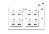
次に、図5Aおよび図5Bを参照して、編集処理を説明する。図5Aは、編集処理前の一覧画像62Aを示す。一覧画像62Aは、4個の集約画像を含む。具体的には、一覧画像62Aは、集約画像12を示す縮小画像12aと、集約画像13を示す縮小画像13aと、集約画像14を示す縮小画像14aと、集約画像15を示す縮小画像15aとを含む。縮小画像12aは、第1画像データ121が示す第1画像と、第2画像データ122が示す第2画像とを示す。同様に、縮小画像13aは、第1画像データ131が示す第1画像と、第2画像データ132が示す第2画像とを示す。縮小画像14aは、第1画像データ141が示す第1画像と、第2画像データ142が示す第2画像とを示す。縮小画像15aは、第1画像データ151が示す第1画像と、第2画像データ152が示す第2画像とを示す。
一覧画像62Aでは、縮小画像13aの第1画像は「裏面b」を示す。また、縮小画像13aの第2画像は「表面B」を示す。このように、縮小画像13aは、本来第1画像データが示すべき画像「表面B」と、本来第2画像データが示すべき画像「裏面b」とが逆になっている。
更に、一覧画像62Aの縮小画像14aの第2画像は「裏面d」を示し、縮小画像15aの第2画像は「裏面c」を示す。このように、縮小画像14aと縮小画像15aとは、縮小画像14aの本来第2画像データが示すべき画像「裏面c」と、縮小画像15aの本来第2画像データが示すべき画像「裏面d」とが逆になっている。なお、一覧画像62Aの縮小画像12aの第1画像は「表面A」を示し、第2画像は「裏面a」を示しているので、正常である。
図5Bは、図5Aの一覧画像62Aに対する編集処理後の一覧画像62Bを示す。図5Bに示すように、一覧画像62Bの縮小画像13aの第1画像と第2画像とが入れ替わっている。更に、縮小画像14aの第2画像と、縮小画像15aの第2画像とが入れ替わっている。
図5Aの一覧画像62Aに対して、関連付け部813は、編集処理を実行する。関連付け部813は、ユーザーから受け付けたタッチ操作に基づいて、集約画像に対して編集処理を実行する。ユーザーから受け付けるタッチ操作には、第1タッチ操作と、第2タッチ操作とがある。すなわち、タッチ操作には、入れ替える画像の第1候補をタッチする第1タッチ操作と、第1候補の画像と入れ替えたい第2候補の画像をタッチする第2タッチ操作とがある。具体的には、第1タッチ操作は、複数の集約画像のうちの1つに含まれる第1画像又は第2画像をタッチする。第2タッチ操作は、第1タッチ操作の後に続けて、複数の集約画像のうちの1つに含まれる第2画像又は第1画像をタッチする。関連付け部813部は、第1タッチ操作においてタッチされた第1画像又は第2画像と、第2タッチ操作においてタッチされた第2画像又は第1画像とを入れ替える。
図5A及び図5Bを参照しながら具体的に説明する。一覧画像62Aに対して、第1回目の第1タッチ操作として、第1画像データ131が示す第1画像をタッチし、第1回目の第2タッチ操作として、第2画像データ132が示す第2画像をタッチする。第1回目の第1タッチ操作と第2タッチ操作とを行うことによって、縮小画像13aにおける第1画像と第2画像とを入れ替えることができる。
更に、第2回目の第1タッチ操作として、第2画像データ142が示す第2画像をタッチし、第2回目の第2タッチ操作として、第2画像データ152が示す第2画像をタッチする。第2回目の第1タッチ操作と第2タッチ操作とを行うことによって、縮小画像14aにおける第2画像と、縮小画像15aにおける第2画像とを入れ替えることができる。したがって、第1面を読み取る際の各原稿と、第2面を読み取る際の各原稿とを間違った場合であっても、タッチ操作によって容易に修正することができる。
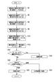
図6は、両面読取処理を示すフローチャートである。両面読取処理は、ステップS2~ステップS22によって実行される。
ステップS2:画像生成部811は、画像読取部10から受信した第1面データに基づいて、複数枚の原稿に対応する第1画像データを生成する。処理は、ステップS4に進む。
ステップS4:記号割当部812は、複数の第1画像データに第1記号を割り当てる。処理は、ステップS6に進む。
ステップS6:画像生成部811は、画像読取部10から受信した第2面データに基づいて、複数枚の原稿に対応する第2画像データを生成する。処理は、ステップS8に進む。
ステップS8:記号割当部812は、複数の第2画像データに第2記号を割り当てる。処理は、ステップS10に進む。
ステップS10:関連付け部813は、第1記号と第2記号とに基づいて、複数の第1画像データと複数の第2画像データとを関連付ける。処理は、ステップS12に進む。
ステップS12:画像集約部814は、第1画像データと第2画像データとに基づいて、集約画像又は一覧画像をプレビュー表示させる。処理は、ステップS14に進む。
ステップS14:関連付け部813は、表示部61に集約画像又は一覧画像がプレビュー表示されている場合に、ユーザーから編集操作があるか否かを判定する。ユーザーから編集操作があると関連付け部813が判定した場合は(ステップS14でYes)、処理は、ステップS16に進む。ユーザーから編集操作がないと関連付け部813が判定した場合は(ステップS14でNo)、処理は、ステップS18に進む。
ステップS16:関連付け部813は、ユーザーによるタッチ操作に基づいて、集約画像データ又は一覧画像データの構成を編集する。処理は、ステップS18に進む。
ステップS18:制御部80は、ユーザーから印刷指示又は送信指示があるか否かを判定する。ユーザーから印刷指示があると制御部80が判定した場合は(ステップS18で印刷)、処理は、ステップS20に進む。ユーザーから送信指示があると制御部80が判定した場合は(ステップS18で送信)、処理は、ステップS22に進む。
ステップS20:制御部80は、ユーザーの指示に応じて、集約画像を印刷する。両面読取処理は、終了する。
ステップS22:制御部80は、ユーザーの指示に応じて、集約画像データを外部装置に送信する。両面読取処理は、終了する。
以上のように、本実施形態の画像形成装置100によれば、表面の画像データと裏面の画像データとの組み合わせを間違って関連付ける可能性を低減することができる。更に、第1面を読み取る際の各原稿と、第2面を読み取る際の各原稿とを間違った場合であっても、タッチ操作によって容易に修正することができる。
以上、図面(図1~図6)を参照しながら本発明の実施形態を説明した。但し、本発明は、上記の実施形態に限られるものではなく、その要旨を逸脱しない範囲で種々の態様において実施することが可能である(例えば、下記に示す(1)、(2))。図面は、理解しやすくするために、それぞれの構成要素を主体に模式的に示しており、図示された各構成要素の厚み、長さ、個数等は、図面作成の都合上から実際とは異なる。また、上記の実施形態で示す各構成要素の材質や形状、寸法等は一例であって、特に限定されるものではなく、本発明の効果から実質的に逸脱しない範囲で種々の変更が可能である。
(1)本発明の実施形態では、画像形成装置100の一例として、複合機を用いて説明したが、画像形成装置100は、複合機に限定されない。例えば、画像形成装置100は、例えば、スキャナー及び/又はプリンターを備えるパーソナルコンピューターであってもよい。
(2)更に、本発明の実施形態では、画像読取装置の一例として画像形成装置100を説明したが、画像読取装置は、例えばタッチパネルを備えるスキャナーであってもよい。
更に、本発明は、本発明に係る画像読取装置の特徴的な構成手段をステップとする画像読み取り方法として実現したり、それらのステップを含む制御プログラムとして実現したりすることもできる。また、そのプログラムは、CD-ROM等の記録媒体や通信ネットワーク等の伝送媒体を介して流通させることもできる。
本発明は、画像読取装置及び画像形成装置の分野に利用可能である。
Claims (9)
- 原稿台と、
前記原稿台に載置された複数枚の原稿の各々の第1面の画像をそれぞれ示す複数の第1画像データを生成する第1生成部と、
前記原稿台の基準位置に基づいて、前記複数の第1画像データの各々に対して、互いに異なる第1記号を割り当てる第1割当部と、
前記原稿台に載置された前記複数枚の原稿の各々の第2面の画像をそれぞれ示す複数の第2画像データを生成する第2生成部と、
前記基準位置に基づいて、前記複数の第2画像データの各々に対して、互いに異なる第2記号を割り当てる第2割当部と、
前記第1記号及び前記第2記号に基づいて、前記複数の第1画像データの各々と、前記複数の第2画像データの各々とを関連付ける関連付け部と
を備える、画像読取装置。 - 前記原稿台は、前記基準位置を示す目印部を有する、請求項1に記載の画像読取装置。
- 画像を表示する表示部と、
関連付けられた前記第1画像データと前記第2画像データとに基づいて、前記第1面の画像と前記第2面の画像とを集約した集約画像を示す集約画像データを生成する第3生成部と、
前記集約画像データに基づいて、前記表示部に前記集約画像をプレビュー表示させる表示制御部と
を更に備える、請求項1に記載の画像読取装置。 - 複数の前記集約画像データに基づいて、一覧画像データを生成する第4生成部を更に備え、
前記表示制御部は、前記一覧画像データに基づいて、前記表示部に一覧画像を表示させ、
前記一覧画像は、複数の前記集約画像を示す、請求項3に記載の画像読取装置。 - 前記表示部に表示された前記集約画像に対するタッチ操作を検知する検知部と、
前記タッチ操作に基づいて、前記集約画像を編集する編集部と
を更に備え、
前記タッチ操作は、複数の前記集約画像のうちの1つに含まれる前記第1画像又は前記第2画像をタッチする第1タッチ操作と、前記複数の集約画像のうちの1つに含まれる前記第2画像又は前記第1画像をタッチする第2タッチ操作とを含み、
前記編集部は、前記第1タッチ操作においてタッチされた前記第1画像又は前記第2画像と、前記第2タッチ操作においてタッチされた前記第2画像又は前記第1画像とを入れ替える、請求項3に記載の画像読取装置。 - 前記第1生成部は、マルチオートクロップ機能を用いて、複数の前記第1画像データを生成し、
前記第2生成部は、マルチオートクロップ機能を用いて、複数の前記第2画像データを生成する、請求項1に記載の画像読取装置。 - 前記第1割当部は、前記原稿台の基準位置に対する前記複数枚の原稿の位置に応じて、前記複数の第1画像データの各々に対して前記第1記号を割り当て、
前記第2生成部は、前記原稿台の基準位置に対する前記複数枚の原稿の位置に応じて、前記複数の第1画像データの各々に対して前記第2記号を割り当てる、請求項1に記載の画像読取装置。 - 前記第1割当部は、前記複数の前記第1画像データの各々に対して順番に数字を割り当て、
前記第2生成部は、前記複数の前記第2画像データの各々に対して順番に数字を割り当てる、請求項1に記載の画像読取装置。 - 複数枚の原稿を読み取る画像読取部と、
記録媒体に画像を形成する画像形成部と
を備えた画像形成装置であって、
前記画像読取部は、
原稿台と、
前記原稿台に載置された前記複数枚の原稿の各々の第1面の画像をそれぞれ示す複数の第1画像データを生成する第1生成部と、
前記原稿台の基準位置に基づいて、前記複数の第1画像データの各々に対して、互いに異なる第1記号を割り当てる第1割当部と、
前記原稿台に載置された前記複数枚の原稿の各々の第2面の画像をそれぞれ示す複数の第2画像データを生成する第2生成部と、
前記基準位置に基づいて、前記複数の第2画像データの各々に対して、互いに異なる第2記号を割り当てる第2割当部と、
前記第1記号及び前記第2記号に基づいて、前記複数の第1画像データの各々と、前記複数の第2画像データの各々とを関連付ける関連付け部と
を備える、画像形成装置。
Priority Applications (2)
| Application Number | Priority Date | Filing Date | Title |
|---|---|---|---|
| US17/273,793 US11240400B2 (en) | 2018-09-06 | 2019-08-02 | Image reading and image forming apparatus relating image data pieces of front and back sides of documents based on different symbols assigned |
| JP2020541073A JPWO2020049923A1 (ja) | 2018-09-06 | 2019-08-02 | 画像読取装置及び画像形成装置 |
Applications Claiming Priority (2)
| Application Number | Priority Date | Filing Date | Title |
|---|---|---|---|
| JP2018-166941 | 2018-09-06 | ||
| JP2018166941 | 2018-09-06 |
Publications (1)
| Publication Number | Publication Date |
|---|---|
| WO2020049923A1 true WO2020049923A1 (ja) | 2020-03-12 |
Family
ID=69722451
Family Applications (1)
| Application Number | Title | Priority Date | Filing Date |
|---|---|---|---|
| PCT/JP2019/030502 Ceased WO2020049923A1 (ja) | 2018-09-06 | 2019-08-02 | 画像読取装置及び画像形成装置 |
Country Status (3)
| Country | Link |
|---|---|
| US (1) | US11240400B2 (ja) |
| JP (1) | JPWO2020049923A1 (ja) |
| WO (1) | WO2020049923A1 (ja) |
Citations (3)
| Publication number | Priority date | Publication date | Assignee | Title |
|---|---|---|---|---|
| JP2006339770A (ja) * | 2005-05-31 | 2006-12-14 | Canon Inc | 画像処理システムおよびその制御方法 |
| JP2007017872A (ja) * | 2005-07-11 | 2007-01-25 | Sharp Corp | 原稿読取り装置 |
| JP2009100211A (ja) * | 2007-10-16 | 2009-05-07 | Sharp Corp | 画像読取装置及び画像読取方法 |
Family Cites Families (2)
| Publication number | Priority date | Publication date | Assignee | Title |
|---|---|---|---|---|
| JP4861255B2 (ja) * | 2007-06-14 | 2012-01-25 | 株式会社リコー | 画像形成装置、画像形成方法およびプログラム |
| JP6869118B2 (ja) * | 2017-06-14 | 2021-05-12 | シャープ株式会社 | 画像読取装置、前記画像読取装置を備えた画像処理装置、画像読取方法、画像読取プログラムおよび記録媒体 |
-
2019
- 2019-08-02 JP JP2020541073A patent/JPWO2020049923A1/ja active Pending
- 2019-08-02 WO PCT/JP2019/030502 patent/WO2020049923A1/ja not_active Ceased
- 2019-08-02 US US17/273,793 patent/US11240400B2/en not_active Expired - Fee Related
Patent Citations (3)
| Publication number | Priority date | Publication date | Assignee | Title |
|---|---|---|---|---|
| JP2006339770A (ja) * | 2005-05-31 | 2006-12-14 | Canon Inc | 画像処理システムおよびその制御方法 |
| JP2007017872A (ja) * | 2005-07-11 | 2007-01-25 | Sharp Corp | 原稿読取り装置 |
| JP2009100211A (ja) * | 2007-10-16 | 2009-05-07 | Sharp Corp | 画像読取装置及び画像読取方法 |
Also Published As
| Publication number | Publication date |
|---|---|
| US11240400B2 (en) | 2022-02-01 |
| US20210203806A1 (en) | 2021-07-01 |
| JPWO2020049923A1 (ja) | 2021-08-12 |
Similar Documents
| Publication | Publication Date | Title |
|---|---|---|
| US11630621B2 (en) | Information processing apparatus and non-transitory computer readable medium | |
| US9876928B2 (en) | Image processing device, image processing method, and non-transitory computer-readable medium | |
| JP2019004298A (ja) | 画像読取装置、前記画像読取装置を備えた画像処理装置、画像読取方法、画像読取プログラムおよび記録媒体 | |
| JP2009194913A (ja) | 画像読取装置、画像形成装置、および画像読取方法 | |
| US20090190164A1 (en) | Method and apparatus for forming image | |
| CN105472202A (zh) | 图像形成装置和图像形成方法 | |
| JP5942869B2 (ja) | 制御装置、電子機器、画像形成装置及びプログラム | |
| EP3648107A1 (en) | Image processing apparatus | |
| JP2011188294A (ja) | 画像形成装置、画像形成システム、印刷指示装置、画像形成装置用または印刷指示装置用プログラム、および、画像形成方法 | |
| JPWO2020049923A1 (ja) | 画像読取装置及び画像形成装置 | |
| CN106484338B (zh) | 打印装置以及打印装置的控制方法 | |
| JP2020095116A (ja) | 画像形成装置、画像形成システム、画像形成システムの制御方法及びプログラム | |
| CN104301573A (zh) | 图像形成装置 | |
| JP7402414B2 (ja) | 画像形成装置 | |
| JP2013153374A (ja) | 操作受付装置、画像形成装置及びプログラム | |
| JP2009124331A (ja) | 原稿画像集約装置および原稿画像集約方法 | |
| JP6648839B2 (ja) | 画像読取装置 | |
| JP2010056603A (ja) | 画像処理システム | |
| JP6690353B2 (ja) | 印刷制御装置、印刷装置、印刷システム、印刷制御方法及びプログラム | |
| JP2020182144A (ja) | 画像形成装置 | |
| JP2011055267A (ja) | 画像形成装置および整列プログラム | |
| JP2020031320A (ja) | 画像形成装置及び画像表示方法 | |
| JP6077022B2 (ja) | 画像形成装置及び画像形成方法 | |
| JP2006074120A (ja) | 画像形成装置および画像形成方法 | |
| JP2024137504A (ja) | 画像処理システム、及び画像処理プログラム |
Legal Events
| Date | Code | Title | Description |
|---|---|---|---|
| 121 | Ep: the epo has been informed by wipo that ep was designated in this application |
Ref document number: 19857039 Country of ref document: EP Kind code of ref document: A1 |
|
| ENP | Entry into the national phase |
Ref document number: 2020541073 Country of ref document: JP Kind code of ref document: A |
|
| NENP | Non-entry into the national phase |
Ref country code: DE |
|
| 122 | Ep: pct application non-entry in european phase |
Ref document number: 19857039 Country of ref document: EP Kind code of ref document: A1 |