WO2020045097A1 - サスペンション装置 - Google Patents
サスペンション装置 Download PDFInfo
- Publication number
- WO2020045097A1 WO2020045097A1 PCT/JP2019/032003 JP2019032003W WO2020045097A1 WO 2020045097 A1 WO2020045097 A1 WO 2020045097A1 JP 2019032003 W JP2019032003 W JP 2019032003W WO 2020045097 A1 WO2020045097 A1 WO 2020045097A1
- Authority
- WO
- WIPO (PCT)
- Prior art keywords
- air
- compressor
- suspension
- suspensions
- compressed air
- Prior art date
- Legal status (The legal status is an assumption and is not a legal conclusion. Google has not performed a legal analysis and makes no representation as to the accuracy of the status listed.)
- Ceased
Links
Images



Classifications
-
- B—PERFORMING OPERATIONS; TRANSPORTING
- B60—VEHICLES IN GENERAL
- B60G—VEHICLE SUSPENSION ARRANGEMENTS
- B60G17/00—Resilient suspensions having means for adjusting the spring or vibration-damper characteristics, for regulating the distance between a supporting surface and a sprung part of vehicle or for locking suspension during use to meet varying vehicular or surface conditions, e.g. due to speed or load
- B60G17/02—Spring characteristics, e.g. mechanical springs and mechanical adjusting means
- B60G17/04—Spring characteristics, e.g. mechanical springs and mechanical adjusting means fluid spring characteristics
- B60G17/056—Regulating distributors or valves for hydropneumatic systems
-
- B—PERFORMING OPERATIONS; TRANSPORTING
- B60—VEHICLES IN GENERAL
- B60G—VEHICLE SUSPENSION ARRANGEMENTS
- B60G17/00—Resilient suspensions having means for adjusting the spring or vibration-damper characteristics, for regulating the distance between a supporting surface and a sprung part of vehicle or for locking suspension during use to meet varying vehicular or surface conditions, e.g. due to speed or load
- B60G17/015—Resilient suspensions having means for adjusting the spring or vibration-damper characteristics, for regulating the distance between a supporting surface and a sprung part of vehicle or for locking suspension during use to meet varying vehicular or surface conditions, e.g. due to speed or load the regulating means comprising electric or electronic elements
-
- B—PERFORMING OPERATIONS; TRANSPORTING
- B60—VEHICLES IN GENERAL
- B60G—VEHICLE SUSPENSION ARRANGEMENTS
- B60G17/00—Resilient suspensions having means for adjusting the spring or vibration-damper characteristics, for regulating the distance between a supporting surface and a sprung part of vehicle or for locking suspension during use to meet varying vehicular or surface conditions, e.g. due to speed or load
- B60G17/02—Spring characteristics, e.g. mechanical springs and mechanical adjusting means
- B60G17/04—Spring characteristics, e.g. mechanical springs and mechanical adjusting means fluid spring characteristics
- B60G17/052—Pneumatic spring characteristics
-
- B—PERFORMING OPERATIONS; TRANSPORTING
- B60—VEHICLES IN GENERAL
- B60G—VEHICLE SUSPENSION ARRANGEMENTS
- B60G2202/00—Indexing codes relating to the type of spring, damper or actuator
- B60G2202/10—Type of spring
- B60G2202/15—Fluid spring
- B60G2202/152—Pneumatic spring
-
- B—PERFORMING OPERATIONS; TRANSPORTING
- B60—VEHICLES IN GENERAL
- B60G—VEHICLE SUSPENSION ARRANGEMENTS
- B60G2400/00—Indexing codes relating to detected, measured or calculated conditions or factors
- B60G2400/25—Stroke; Height; Displacement
-
- B—PERFORMING OPERATIONS; TRANSPORTING
- B60—VEHICLES IN GENERAL
- B60G—VEHICLE SUSPENSION ARRANGEMENTS
- B60G2500/00—Indexing codes relating to the regulated action or device
- B60G2500/20—Spring action or springs
- B60G2500/205—Air-compressor operation
Definitions
- the present invention relates to a suspension device that is provided in, for example, a four-wheel vehicle and controls the supply and discharge of compressed air to an air suspension of each wheel to adjust the vehicle height.
- Patent Document 1 discloses a suspension device that controls the supply and discharge of compressed air to and from an air suspension provided for each wheel to adjust the vehicle height.
- this suspension device when the front wheel air suspension and the rear wheel air suspension communicate with each other, the pressure (compressed air) escapes from the relatively high pressure air suspension to the low pressure air suspension, so that the front wheel air suspension and the rear wheel It is necessary to adjust the vehicle height alternately with the air suspension.
- the purpose of the present invention is to improve responsiveness during reverse roll control.
- a suspension device includes: The left air suspension on the front wheel side, The right air suspension on the front wheel side, The left air suspension on the rear wheel side, The right air suspension on the rear wheel side, A compressor for supplying compressed air to the left air suspension on the front wheel side, the right air suspension on the front wheel side, the left air suspension on the rear wheel side, and the right air suspension on the rear wheel side.
- a compressor for supplying compressed air to the left air suspension on the front wheel side, the right air suspension on the front wheel side, the left air suspension on the rear wheel side, and the right air suspension on the rear wheel side.
- the responsiveness at the time of reverse roll control can be improved.
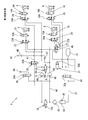
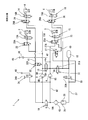
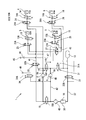
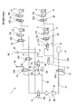
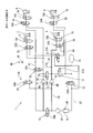
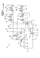
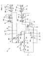
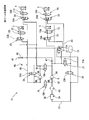
- FIG. 2 is a pneumatic system diagram of the suspension device according to the first embodiment. It is explanatory drawing of 1st Embodiment, and shows the pneumatic system diagram in a simultaneous mode.
- FIG. 4 is an explanatory diagram of the first embodiment, showing a pneumatic system diagram when the vehicle height adjustment (elevation) of the left and right rear wheel air suspensions is completed first in the simultaneous mode.
- FIG. 4 is an explanatory diagram of the first embodiment, and shows a pneumatic system diagram in an alternate mode (up).
- FIG. 2 is an explanatory diagram of the first embodiment, and shows a pneumatic system diagram when a pressure accumulator is filled with compressed air.
- FIG. 4 is an explanatory diagram of the first embodiment, and shows a pneumatic system diagram during a left turn in a reverse roll mode.
- FIG. 3 is an explanatory diagram of the first embodiment, and shows a pneumatic system diagram at the time of turning right in a reverse roll mode.
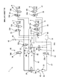
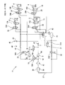
- It is a pneumatic system diagram of a suspension device concerning a 2nd embodiment.
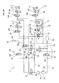
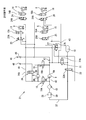
- 2nd Embodiment and shows the pneumatic system diagram in a simultaneous mode.
- the suspension device 1 has a suspension control device (not shown) including an ECU (Electronic Control Unit), and drives each control valve, which will be described later, and controls a compressor 8 (first compressor) and a compressor 9 (second compressor). The operation is controlled by the suspension control device.
- ECU Electronic Control Unit
- a suspension device 1 includes an air suspension 3 interposed between a vehicle body and a front left wheel, an air suspension 4 interposed between a vehicle body and a front right wheel, and a suspension device
- the vehicle includes an air suspension 5 interposed therebetween, and an air suspension 6 interposed between the vehicle body and the right rear wheel.
- the pneumatic system of the suspension device 1 including the left and right front wheel air suspensions 3 and 4 (front wheel left and right air suspensions) and the left and right rear wheel air suspensions 5 and 6 (rear wheel left and right air suspensions) It is constituted by a closed circuit that uses the compressed air stored in the pressure accumulator 10 as a working fluid.
- the suspension device 1 is driven by a solenoid 13A to control the supply and discharge of compressed air to and from the air suspension 3 of the left front wheel, and is driven by the solenoid 14A to supply and discharge compressed air to and from the air suspension 4 of the right front wheel.
- a control valve 16 for controlling the supply and discharge of air.
- the suspension device 1 is a simultaneous mode in which the left and right front wheel air suspensions 3 and 4 and the right and left rear wheel air suspensions 5 and 6 are simultaneously lifted using individual compressors 8 and 9, respectively. And the air suspensions 5 and 6 of the left and right rear wheels are alternately raised and lowered by using two compressors 8 and 9, and the air suspensions 3 and 4 of the left and right front wheels when the running scene of the vehicle is in a roll state. And the left and right rear air suspensions 5 and 6 are independently driven by the respective compressors 8 and 9 so as to reversely roll. It has a reverse roll mode for exchanging compressed air between them.
- control modes of the above-described simultaneous mode, alternate mode, and reverse roll mode are selected by switching the control valves 23, 24, 25, 26, and 27 arranged in the pneumatic system shown in FIG.
- the control valves 23, 24, 25, 26, and 27 are the same type of solenoid valves (directional control valves).
- the suspension device 1 supplies air to the air suspensions 3 and 4 of the left and right front wheels by one compressor 8 or two compressors 8 and 9 and supplies air to the air suspensions 5 and 6 of the right and left rear wheels.
- It has control valves 18 and 19 which are switched when selecting whether the exhaust is performed by one compressor 9 or two compressors 8 and 9.
- the control valve 18 is driven by a solenoid 18A, and controls communication / cutoff between an air supply port 8A of the compressor 8 and an air supply port 9A of the compressor 9.
- the control valve 19 is driven by a solenoid 19A, and controls the communication / cutoff between the exhaust port 8B of the compressor 8 and the exhaust port 9B of the compressor 9.
- the control valves 18 and 19 are the same type of solenoid valves (directional control valves).
- the suspension device 1 has a control valve 31 that is driven by a solenoid 31A and controls communication / cutoff between the accumulator 10 and an air supply port 9A of the compressor 9.
- the suspension device 1 is driven by a solenoid 32A to connect the pipe 41 on the air suspension 3, 4, 5, 6 side to the air supply port 8A of the compressor 8, and to connect the pipe 41 to the exhaust port of the compressor 8. It has a control valve 32 for switching between a connection that communicates with the port 8B.
- the suspension device 1 has a control valve 33 driven by a solenoid 33A to control the communication / cutoff between the exhaust port 9B of the compressor 9 and the accumulator 10. Further, the suspension device 1 has a control valve 34 that is driven by a solenoid 34A and controls communication / cutoff between an exhaust port 48 and a pipe 42 having one end connected to an exhaust port 9B of the compressor 9. A dryer 43 is provided in the pipe 37 between the other end of the pipe 42 and the control B 34. Further, a throttle valve 38 and a check valve 39 are provided in parallel in the pipe line 37.
- Figure 2 shows the pneumatic system diagram in the simultaneous mode.
- a pneumatic system in which the compressor 8 supplies air to the left and right front wheel air suspensions 3, 4 and a pneumatic system in which the compressor 9 supplies air to the left and right rear wheel air suspensions 5, 6 are formed.
- the solenoid 31A of the control valve 31 and the solenoid 18A of the control valve 18 are energized to connect the air supply port 8A of the compressor 8 and the air supply port 9A of the compressor 9 to the accumulator 10.
- the solenoid 19A of the control valve 19 is de-energized, and the exhaust port 8B of the compressor 8 and the exhaust port 9B of the compressor 9 are shut off. Further, the solenoid 32A of the control valve 32, the solenoid 13A of the control valve 13 and the solenoid 14A of the control valve 14 are energized, and the solenoid 23A of the control valve 23 and the solenoid 24A of the control valve 24 are de-energized.
- the exhaust port 8B is communicated with the air suspensions 3, 4.
- the solenoid 27A of the control valve 27, the solenoid 15A of the control valve 15, and the solenoid 16A of the control valve 16 are energized, and the solenoid 33A of the control valve 33, the solenoid 25A of the control valve 25, and the control valve 26 are connected.
- the solenoid 26A is de-energized and the exhaust port 9B of the compressor 9 is communicated with the air suspensions 5, 6, the compressed air fed from the compressor 9 is supplied to the air suspensions 5, 6 of the left and right rear wheels. The height of the suspensions 5 and 6 increases.
- the solenoid 15A of the control valve 15 and the solenoid 16A of the control valve 16 are de-energized.
- the supply of the compressed air to the air suspensions 5 and 6 of the left and right rear wheels is cut off, and the solenoid 19A of the control valve 19 is energized to communicate the exhaust port 8B of the compressor 8 with the exhaust port 9B of the compressor 9. .
- the compressed air sent from the compressor 8 and the compressed air sent from the compressor 9 are supplied to the air suspensions 3 and 4 of the left and right front wheels, and the remaining rising speeds of the air suspensions 3 and 4 of the left and right front wheels are reduced. Can be enhanced.
- the solenoid 13A of the control valve 13 and the solenoid 14A of the control valve 14 are de-energized, and the left and right air suspensions 3 are turned off. , 4 is shut off, and the solenoid 19A of the control valve 19 is energized to make the exhaust port 8B of the compressor 8 communicate with the exhaust port 9B of the compressor 9.
- the compressed air sent from the compressor 8 and the compressed air sent from the compressor 9 are supplied to the left and right rear wheel air suspensions 5, 6, and the remaining lift of the left and right rear wheel air suspensions 5, 6 is increased.
- Speed can be increased.
- FIG. 4 shows the pneumatic pressure in the alternate ascending mode in which the air suspensions 3 and 4 of the left and right front wheels and the air suspensions 5 and 6 of the left and right rear wheels are alternately raised by using the two compressors 8 and 9 among the alternate modes described above.
- the system diagram is shown.
- the solenoid 19A of the control valve 19 is energized to make the exhaust port 8B of the compressor 8 communicate with the exhaust port 9B of the compressor 9 as compared with the simultaneous mode (see FIG. 2).
- the solenoid 27A When the solenoid 27A is de-energized, the conduit 41 communicates with the conduits 43 on the air suspensions 5 and 6 for the left and right rear wheels.
- the solenoids 13A and 14A of the control valves 13 and 14 are energized, and the solenoids 15A and 16A of the control valves 15 and 16 are de-energized. Can be increased by the two compressors 8 and 9.
- the vehicle height of the air suspensions 5 and 6 for the left and right rear wheels is reduced by two compressors. 8, 9 can be raised.
- FIG. 5 shows the pneumatic pressure in the alternate descent mode in which the air suspensions 3 and 4 for the left and right front wheels and the air suspensions 5 and 6 for the left and right rear wheels are alternately lowered using the two compressors 8 and 9 among the above-described alternate modes.
- the system diagram is shown.
- the solenoid 19A of the control valve 19 and the solenoid 33A of the control valve 33 are energized to connect the exhaust port 8B of the compressor 8 and the exhaust port 9B of the compressor 9 to the pressure accumulator 10, and the control valve 18
- the solenoid 18A By energizing the solenoid 18A, the air supply port 8A of the compressor 8 and the air supply port 9A of the compressor 9 communicate with the pipeline 41.
- the solenoids 13A and 14A of the control valves 13 and 14 are energized, and the solenoids 15A and 16A of the control valves 15 and 16 are de-energized.
- the solenoids 15A and 16A of the control valves 15 and 16 are energized, and the solenoids 13A and 14A of the control valves 13 and 14 are de-energized.
- FIG. 6 shows a pneumatic system diagram when the accumulator 10 is filled with compressed air.
- the suspension control device detects that the internal pressure of the accumulator 10 is insufficient, the suspension control device energizes the solenoid 18A of the control valve 18 to connect the air supply port 8A of the compressor 8 with the air supply port 9A of the compressor 9.
- the solenoids 19A and 33A of the control valves 19 and 33 are energized to connect the exhaust port 8B of the compressor 8 and the exhaust port 9B of the compressor 9 to the accumulator 10.
- the two compressors 8 and 9 are operated in this state, the air introduced from the atmosphere inlet 45 is charged into the accumulator 10 via the filter 46 and the check valve 47.
- FIG. 7 shows a pneumatic system diagram when the compressed air of the accumulator 10 is discharged into the atmosphere.
- the suspension control device detects that the internal pressure of the pressure accumulator 10 is excessive, the suspension control device energizes the solenoids 33A and 34A of the control valves 33 and 34 to connect the pressure accumulator 10 to the exhaust port 48.
- the compressed air of the accumulator 10 is discharged from the exhaust port 48 to the atmosphere.
- the compressed air discharged from the pressure accumulator 10 passes through the dryer 43, whereby the desiccant in the dryer 43 is dried, and the function as the dryer 43 can be restored.
- FIG. 8 shows a pneumatic system diagram when turning left in the reverse roll mode.
- the solenoids 13A and 23A of the control valves 13 and 23 are energized to connect the air suspension 3 of the left front wheel to the air supply port 8A of the compressor 8, and the solenoids 14A and 14A of the control valves 14 and 32 are connected.
- the air suspension 4 of the right front wheel is communicated with the exhaust port 8B of the compressor 8.
- the compressed air of the air suspension 3 of the left front wheel is sent to the air suspension 4 of the right front wheel (outer wheel at the time of turning) by using the compressor 8.
- the solenoids 13A and 23A of the control valves 13 and 23 are energized, the solenoids 15A and 25A of the control valves 15 and 25 are energized to communicate the left rear wheel air suspension 5 with the air supply port 9A of the compressor 9.
- the solenoids 16A and 27A of the control valves 16 and 27 are energized to connect the right rear wheel air suspension 6 to the exhaust port 9B of the compressor 9. Thereby, the compressed air of the air suspension 5 of the left rear wheel (inner wheel at the time of turning) is sent to the air suspension 6 of the right rear wheel (outer wheel at the time of turning) by using the compressor 9.
- FIG. 9 shows a pneumatic system diagram when turning right in the reverse roll mode.
- the solenoids 14A and 24A of the control valves 14 and 24 are energized to connect the air suspension 4 of the right front wheel to the air supply port 8A of the compressor 8 and the solenoids 13A of the control valves 13 and 32. , 32A to make the left front wheel air suspension 3 communicate with the exhaust port 8B of the compressor 8.
- the compressed air of the air suspension 4 of the right front wheel is sent to the air suspension 3 of the left front wheel (outer wheel at the time of turning) by using the compressor 8.
- the solenoids 14A and 24A of the control valves 14 and 24 are energized, the solenoids 16A and 26A of the control valves 16 and 26 are energized to connect the air suspension 6 of the right rear wheel to the air supply port 9A of the compressor 9.
- the solenoids 15A, 27A of the control valves 15, 27 are energized to connect the left rear wheel air suspension 5 to the exhaust port 9B of the compressor 9.
- the solenoid 18A of the control valve 18 is energized and the compressor 8 is energized.
- the communication between the air supply port 8A of the compressor 9 and the air supply port 9A of the compressor 9 is conducted, and the solenoid 19A of the control valve 19 is energized to communicate the exhaust port 8B of the compressor 8 with the exhaust port 9B of the compressor 9.
- the suspension control device calculates a curvature of a forward curve obtained from an image signal of a vehicle-mounted camera (outside world recognizing means) and wireless communication information (C2X, V2X) such as road-vehicle communication, and a detection signal of the vehicle state detecting means.
- C2X, V2X wireless communication information
- the reverse roll mode is selected, and in the case of a left turn, the compressed air of the left front wheel air suspension 3 is compressed by the compressor 8 to the right front wheel.
- the compressed air of the left rear wheel air suspension 5 is sent to the right rear wheel air suspension 6 using the compressor 9.
- the compressed air of the air suspensions 3, 5 of the inner wheel during turning is forcibly sent to the air suspensions 4, 6 of the outer wheel during turning using the compressors 8, 9.
- the vehicle height of the air suspensions 3 and 5 of the inner wheels during turning decreases, and at the same time, the vehicle height of the air suspensions 4 and 6 of the outer wheels during turning increases.
- the vehicle assumes a reverse roll posture in which the vehicle body is inclined in a direction opposite to the original roll direction.
- the compressed air of the right front wheel air suspension 4 is sent to the left front wheel air suspension 3 using the compressor 8 and the compressed air of the right rear wheel air suspension 6 is used using the compressor 9.
- the air is supplied to the air suspension 5 of the left rear wheel. That is, the compressed air of the air suspensions 4 and 6 of the inner wheel during turning is forcibly sent to the air suspensions 3 and 5 of the outer wheel during turning using the compressors 8 and 9.
- the vehicle height of the inner wheel air suspensions 4, 6 during turning decreases, and at the same time, the vehicle height of the outer wheel air suspensions 3, 5 during turning increases.
- the vehicle assumes a reverse roll posture in which the vehicle body is inclined in a direction opposite to the original roll direction.
- the suspension control unit is connected to other control units (ECU) installed in the vehicle including the control unit of the on-board camera by CAN (Controller Area Network) and can communicate with each other by CAN signals. is there.
- ECU Controller Area Network
- In-vehicle LAN communication is not limited to CAN.
- the first embodiment when the running scene of the vehicle is in a roll state, compressed air is exchanged between the left and right air suspensions 3 and 4 of the front wheels by the compressor 8 and the left and right air suspensions 5 and 5 of the rear wheels are compressed by the compressor 9.
- the compressor 8 By transmitting and receiving compressed air between the left and right wheels 6, reverse rolls are generated independently by the left and right front wheel air suspensions 3, 4 and the left and right rear wheel air suspensions 5, 6.
- the vehicle height adjustment of the left and right front wheel air suspensions 3 and 4 and the vehicle height adjustment of the left and right rear wheel air suspensions 5 and 6 are performed in parallel. Can be improved.
- the operation and effect of the first embodiment will be described.
- a compressor for supplying compressed air to the front wheel side air suspension and the rear wheel side air suspension.
- the front wheel air suspension and the rear wheel air suspension are independent of each other, and the left and right air suspensions are compressed by a compressor so as to generate reverse rolls. Since the compressed air is exchanged, the height adjustment of the front wheel air suspension and the height adjustment of the rear wheel air suspension can be performed simultaneously. Responsiveness can be improved.
- the compressor includes a first compressor that supplies compressed air to a front-wheel-side air suspension and a second compressor that supplies compressed air to a rear-wheel-side air suspension. Transmission and reception of compressed air between the left and right air suspensions on the front wheel side using compressed air and transmission and reception of compressed air between the left and right air suspensions on the rear wheel side using the second compressor.
- the transfer of the compressed air between the left and right air suspensions is completed first, the remaining compressed air between the left and right air suspensions of the other side wheel is transferred using the two compressors of the first compressor and the second compressor. The time required to transfer the remaining compressed air between the left and right air suspensions of the side wheels can be reduced.
- the running scene is recognized based on the vehicle communication signal such as CAN obtained from the information of the outside world recognition means or the wireless communication information. It is possible to apply.
- the suspension control device recognizes that the running scene is in a roll state based on an image signal (information) obtained from an onboard camera (outside world recognition means) and wireless communication information such as road-vehicle communication.
- the configuration can be such that the traveling scene is recognized as being in a roll state based on the detection result of the vehicle height detecting means for detecting or estimating the vehicle height.
- a conventional vehicle control logic is used as the logic for determining the driving scene from the detected or estimated vehicle height.
- FIG. 10 shows a pneumatic system diagram of the suspension device 21 according to the second embodiment.
- the suspension device 21 does not have the control valve 32 (see FIG. 1) used in the suspension device 1 according to the first embodiment.
- a throttle valve 38 and a check valve 39 are provided in parallel in a pipe line 37 between the exhaust port 9 ⁇ / b> B of the compressor 9 (second compressor) and the accumulator 10.
- FIG. 11 shows a pneumatic system diagram of the suspension device 21 in the simultaneous mode.
- the solenoid 31A of the control valve 31 and the solenoid 18A of the control valve 18 are energized to connect the air supply port 8A of the compressor 8 and the air supply port 9A of the compressor 9 to the accumulator 10.
- the solenoid 19A of the control valve 19 is de-energized, and the exhaust port 8B of the compressor 8 and the exhaust port 9B of the compressor 9 are shut off.
- the solenoid 13A of the control valve 13 and the solenoid 14A of the control valve 14 are energized to connect the exhaust port 8B of the compressor 8 to the air suspensions 3, 4.
- the compressed air fed from the compressor 8 is supplied to the air suspensions 3 and 4 of the left and right front wheels, and the height of the air suspensions 3 and 4 increases.
- the solenoid 27A of the control valve 27, the solenoid 15A of the control valve 15 and the solenoid 16A of the control valve 16 are energized to communicate the exhaust port 9B of the compressor 9 with the air suspensions 5 and 6, so that the compressor 9 is pumped.
- the compressed air thus supplied is supplied to the air suspensions 5 and 6 of the left and right rear wheels, and the vehicle height of the air suspensions 5 and 6 rises.
- the solenoid 19A of the control valve 19 is energized to connect the exhaust port 8B of the compressor 8 and the exhaust port 9B of the compressor 9 to each other. Communicate.
- the compressed air sent from the compressor 8 and the compressed air sent from the compressor 9 are supplied to the left and right front wheel air suspensions 3 and 4, and the remaining rising speeds of the left and right front wheel air suspensions 3 and 4 are reduced. Can be enhanced.
- the solenoid 19A of the control valve 19 is energized to communicate the exhaust port 8B of the compressor 8 with the exhaust port 9B of the compressor 9. Let it.
- the compressed air sent from the compressor 8 and the compressed air sent from the compressor 9 are supplied to the left and right rear wheel air suspensions 5, 6, and the remaining lift of the left and right rear wheel air suspensions 5, 6 is increased.
- Speed can be increased.
- the control valve is provided for the simultaneous mode (see FIG. 11).
- the solenoid 19A of the compressor 19 is energized to make the exhaust port 8B of the compressor 8 communicate with the exhaust port 9B of the compressor 9, and the solenoid 27A of the control valve 27 is de-energized to change the duct 41 to the air suspension 5 of the left and right rear wheels. It communicates with the conduit 43 on the 6 side.
- the vehicle height of the air suspensions 3 and 4 for the left and right front wheels can be increased by the two compressors 8 and 9.
- the solenoids 15A and 16A of the control valves 15 and 16 the vehicle height of the air suspensions 5 and 6 for the left and right rear wheels can be increased by the two compressors 8 and 9.
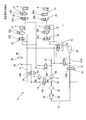
- FIG. 12 shows a pneumatic system diagram when the air suspensions 3 and 4 for the left and right front wheels and the air suspensions 5 and 6 for the left and right rear wheels are alternately lowered.
- the solenoid 19A of the control valve 19 and the solenoid 33A of the control valve 33 are energized to communicate the conduit 41 with the accumulator 10.
- the solenoids 13A and 14A of the control valves 13 and 14 are energized to store the compressed air of the left and right front wheel air suspensions 3 and 4 in the accumulator 10, thereby reducing the vehicle height of the left and right front wheel air suspensions 3 and 4. Can be lowered.
- the solenoids 15A and 16A of the control valves 15 and 16 are energized to store the compressed air of the air suspensions 5 and 6 of the left and right rear wheels in the accumulator 10 so that the vehicles of the air suspensions 5 and 6 of the left and right rear wheels are provided. The height can be lowered.
- FIG. 13 shows a pneumatic system diagram when the accumulator 10 is filled with compressed air.
- the suspension control device detects that the internal pressure of the accumulator 10 is insufficient, the suspension control device energizes the solenoid 18A of the control valve 18 to connect the air supply port 8A of the compressor 8 with the air supply port 9A of the compressor 9.
- the solenoids 19A and 33A of the control valves 19 and 33 are energized to connect the exhaust port 8B of the compressor 8 and the exhaust port 9B of the compressor 9 to the accumulator 10.
- the two compressors 8 and 9 are operated in this state, the air introduced from the atmosphere inlet 45 is stored in the accumulator through the filter 46, the check valve 47, the dryer 43, and the throttle valve 38 and the check valve 39. 10 are filled.
- FIG. 14 shows a pneumatic system diagram when the compressed air of the accumulator 10 is discharged into the atmosphere.
- the suspension control device detects that the internal pressure of the pressure accumulator 10 is excessive, the suspension control device energizes the solenoids 19A, 33A, and 34A of the control valves 19, 33, and 34 to connect the pressure accumulator 10 to the exhaust port 48.
- the compressed air of the accumulator 10 is discharged from the exhaust port 48 to the atmosphere.
- the compressed air discharged from the pressure accumulator 10 passes through the dryer 43, whereby the desiccant in the dryer 43 is dried, and the function as the dryer 43 can be restored.
- FIG. 15 shows a pneumatic system diagram of the suspension device 21 when turning left in the reverse roll mode.
- the suspension control device energizes the solenoids 13A and 23A of the control valves 13 and 23 to connect the air suspension 3 of the left front wheel to the air supply port 8A of the compressor 8 and the control valve 14
- the solenoid 14A By energizing the solenoid 14A, the right front wheel air suspension 4 is communicated with the exhaust port 8B of the compressor 8.
- the compressed air of the air suspension 3 of the left front wheel is sent to the air suspension 4 of the right front wheel (outer wheel at the time of turning) by using the compressor 8.
- the suspension control device supplies power to the solenoids 15A and 25A of the control valves 15 and 25 and supplies air to the compressor 9 by supplying air to the solenoids 15A and 25A of the control valves 15 and 25 at the same time as supplying power to the solenoids 13A and 23A of the control valves 13 and 23.
- the solenoids 16A and 27A of the control valves 16 and 27 are energized to connect the air suspension 6 of the right rear wheel to the exhaust port 9B of the compressor 9.
- the compressed air of the air suspension 5 of the left rear wheel is sent to the air suspension 6 of the right rear wheel (outer wheel at the time of turning) by using the compressor 9.
- the compressors 8 and 9 are used to forcibly send the compressed air of the air suspensions 3 and 5 of the inner wheel at the time of turning to the air suspensions 4 and 6 of the outer wheel at the time of turning.
- the vehicle height of the air suspensions 3 and 5 of the inner wheels decreases while the vehicle height of the air suspensions 4 and 6 of the outer wheels increases at the time of turning.
- the vehicle assumes a reverse roll posture in which the vehicle body is inclined in a direction opposite to the original roll direction.
- FIG. 16 is a pneumatic system diagram of the suspension control device 21 when turning right in the reverse roll mode.
- the suspension control device energizes the solenoids 14A and 24A of the control valves 14 and 24 to connect the air suspension 4 of the right front wheel to the air supply port 8A of the compressor 8 and the control valve 13
- the solenoid 13A is energized to connect the air suspension 3 of the left front wheel to the exhaust port 8B of the compressor 8.
- the compressed air of the air suspension 4 of the right front wheel is sent to the air suspension 3 of the left front wheel (outer wheel at the time of turning) by using the compressor 8.
- the suspension control device supplies power to the solenoids 14A and 24A of the control valves 14 and 24 and simultaneously supplies power to the solenoids 16A and 26A of the control valves 16 and 26 to supply the air suspension 6 of the right rear wheel to the compressor 9.
- the solenoids 15A and 27A of the control valves 15 and 27 are energized to connect the air suspension 5 of the left rear wheel to the exhaust port 9B of the compressor 9.
- the compressed air of the air suspension 6 of the right rear wheel is sent to the air suspension 5 of the left rear wheel (outer wheel at the time of turning) by using the compressor 9.
- the compressors 8 and 9 are used to forcibly send the compressed air of the air suspensions 4 and 6 of the inner wheels during turning to the air suspensions 3 and 5 of the outer wheels during turning.
- the vehicle height of the air suspensions 4, 6 of the inner wheel decreases, and at the same time, the vehicle height of the air suspensions 3, 5 of the outer wheel increase during turning.
- the vehicle assumes a reverse roll posture in which the vehicle body is inclined in a direction opposite to the original roll direction.
- the solenoid 18A of the control valve 18 is energized and the compressor 8 is energized.
- the communication between the air supply port 8A of the compressor 9 and the air supply port 9A of the compressor 9 is conducted, and the solenoid 19A of the control valve 19 is energized to communicate the exhaust port 8B of the compressor 8 with the exhaust port 9B of the compressor 9.
- the same operation and effect as those of the first embodiment can be obtained.
- the control valve 32 of the first embodiment can be omitted. This makes it possible to reduce the objects to be controlled by the suspension control device, and to simplify the control.
- the present invention is not limited to the above-described embodiment, and includes various modifications.
- the above-described embodiments have been described in detail for easy understanding of the present invention, and are not necessarily limited to those having all the configurations described above.
- a part of the configuration of one embodiment can be replaced with the configuration of another embodiment, and the configuration of one embodiment can be added to the configuration of another embodiment.
Landscapes
- Engineering & Computer Science (AREA)
- Mechanical Engineering (AREA)
- Vehicle Body Suspensions (AREA)
Abstract
Description
前輪側の左のエアサスペンションと、
前輪側の右のエアサスペンションと、
後輪側の左のエアサスペンションと、
後輪側の右のエアサスペンションと、
前記前輪側の左のエアサスペンション、前記前輪側の右のエアサスペンション、前記後輪側の左のエアサスペンション、前記後輪側の右のエアサスペンションに圧縮エアを供給するコンプレッサと、を有しており、
車両の走行シーンがロール状態のとき、前記前輪側の左及び右のエアサスペンションと、前記後輪側の左及び右のエアサスペンションとが、それぞれ独立して、逆ロールを発生するように、前記コンプレッサによって、前記前輪の左のエアサスペンションと前記前輪の右のエアサスペンションとの間で、圧縮エアを授受すると共に、前記後輪の左のエアサスペンションと前記後輪側の右のエアサスペンションとの間で圧縮エアを授受する。
以下、第1実施形態に係るサスペンション装置1を4輪自動車(車両)に適用した場合を説明する。なお、サスペンション装置1は、ECU(Electronic Control Unit)からなるサスペンション制御装置(図示省略)を有し、後述する各制御バルブの駆動、コンプレッサ8(第1コンプレッサ)およびコンプレッサ9(第2コンプレッサ)の作動は、当該サスペンション制御装置によって制御される。
第1実施形態によれば、前輪側の左右のエアサスペンションと、後輪側の左右のエアサスペンションと、前輪側のエアサスペンション、後輪側のエアサスペンションに圧縮エアを供給するコンプレッサと、を有するサスペンション装置であって、車両の走行シーンがロール状態のとき、前輪側のエアサスペンションと後輪側のエアサスペンションとはそれぞれ独立して、逆ロールを発生するようにコンプレッサによって左右のエアサスペンション間で圧縮エアを授受させるので、前輪側のエアサスペンションの車高調整と後輪側のエアサスペンションの車高調整とを併行して行うことが可能であり、エアサスペンションを備えたサスペンション装置における逆ロール制御の応答性を向上させることができる。
なお、第1実施形態との共通部分については、同一の称呼および符号を用いることとし、重複する説明を省略する。
Claims (4)
- サスペンション装置であって、該サスペンション装置は、
前輪側の左のエアサスペンションと、
前輪側の右のエアサスペンションと、
後輪側の左のエアサスペンションと、
後輪側の右のエアサスペンションと、
前記前輪側の左のエアサスペンション、前記前輪側の右のエアサスペンション、前記後輪側の左のエアサスペンション、前記後輪側の右のエアサスペンションに圧縮エアを供給するコンプレッサと、を有しており、
車両の走行シーンがロール状態のとき、前記前輪側の左及び右のエアサスペンションと、前記後輪側の左及び右のエアサスペンションとが、それぞれ独立して、逆ロールを発生するように、前記コンプレッサによって、前記前輪の左のエアサスペンションと前記前輪の右のエアサスペンションとの間で、圧縮エアを授受すると共に、前記後輪の左のエアサスペンションと前記後輪側の右のエアサスペンションとの間で圧縮エアを授受することを特徴とするサスペンション装置。 - 請求項1に記載のサスペンション装置において、
前記コンプレッサは、
前記前輪側の左及び右のエアサスペンションに圧縮エアを供給する第1コンプレッサと、
前記後輪側の左及び右のエアサスペンションに圧縮エアを供給する第2コンプレッサと、からなり、
前記第1コンプレッサを用いた前記前輪側の左及び右のエアサスペンション間の圧縮エアの授受と、前記第2コンプレッサを用いた前記後輪側の左及び右のエアサスペンション間の圧縮エアの授受とのうち、一側輪の左及び右のエアサスペンション間の圧縮エアの授受が先に完了すると、前記第1コンプレッサと前記第2コンプレッサとの2つのコンプレッサを用いて、他側輪の左及び右のエアサスペンション間の圧縮エアの残りの授受が行われることを特徴とするサスペンション装置。 - 請求項1または2に記載のサスペンション装置において、
前記走行シーンは、外界認識手段の情報から得られたCAN信号に基づき認識されることを特徴とするサスペンション装置。 - 請求項1または2に記載のサスペンション装置において、
前記走行シーンは、車高を検出または推定する車高検出手段の検出結果に基づき認識されることを特徴とするサスペンション装置。
Priority Applications (5)
| Application Number | Priority Date | Filing Date | Title |
|---|---|---|---|
| KR1020217006151A KR102478656B1 (ko) | 2018-08-29 | 2019-08-15 | 서스펜션 장치 |
| JP2020539334A JP7126550B2 (ja) | 2018-08-29 | 2019-08-15 | サスペンション装置 |
| US17/271,007 US11491840B2 (en) | 2018-08-29 | 2019-08-15 | Suspension device |
| CN201980055285.XA CN112805162A (zh) | 2018-08-29 | 2019-08-15 | 悬架装置 |
| DE112019004309.9T DE112019004309T5 (de) | 2018-08-29 | 2019-08-15 | Federungsvorrichtung |
Applications Claiming Priority (2)
| Application Number | Priority Date | Filing Date | Title |
|---|---|---|---|
| JP2018160619 | 2018-08-29 | ||
| JP2018-160619 | 2018-08-29 |
Publications (1)
| Publication Number | Publication Date |
|---|---|
| WO2020045097A1 true WO2020045097A1 (ja) | 2020-03-05 |
Family
ID=69644186
Family Applications (1)
| Application Number | Title | Priority Date | Filing Date |
|---|---|---|---|
| PCT/JP2019/032003 Ceased WO2020045097A1 (ja) | 2018-08-29 | 2019-08-15 | サスペンション装置 |
Country Status (6)
| Country | Link |
|---|---|
| US (1) | US11491840B2 (ja) |
| JP (1) | JP7126550B2 (ja) |
| KR (1) | KR102478656B1 (ja) |
| CN (1) | CN112805162A (ja) |
| DE (1) | DE112019004309T5 (ja) |
| WO (1) | WO2020045097A1 (ja) |
Cited By (2)
| Publication number | Priority date | Publication date | Assignee | Title |
|---|---|---|---|---|
| JP2023151914A (ja) * | 2022-04-01 | 2023-10-16 | トヨタ自動車株式会社 | 車高調整システム |
| JP2024527469A (ja) * | 2021-06-24 | 2024-07-25 | アップル インコーポレイテッド | 共有圧縮機 |
Families Citing this family (1)
| Publication number | Priority date | Publication date | Assignee | Title |
|---|---|---|---|---|
| CN116194310A (zh) * | 2021-09-28 | 2023-05-30 | 华为技术有限公司 | 电磁阀总成、空气悬架系统、车辆、控制方法及相关设备 |
Citations (4)
| Publication number | Priority date | Publication date | Assignee | Title |
|---|---|---|---|---|
| JPH06115338A (ja) * | 1992-10-07 | 1994-04-26 | Toyota Motor Corp | エアサスペンション装置 |
| JPH10151928A (ja) * | 1996-09-25 | 1998-06-09 | Toyota Motor Corp | 車高調整装置 |
| JP2009255779A (ja) * | 2008-04-17 | 2009-11-05 | Toyota Motor Corp | 車高調整システム |
| JP2010064589A (ja) * | 2008-09-10 | 2010-03-25 | Nissan Motor Co Ltd | 減衰力制御方法及び減衰力制御システム |
Family Cites Families (15)
| Publication number | Priority date | Publication date | Assignee | Title |
|---|---|---|---|---|
| JPS60248413A (ja) * | 1984-05-22 | 1985-12-09 | Daihatsu Motor Co Ltd | 車両の姿勢制御装置 |
| US4834418A (en) * | 1987-04-20 | 1989-05-30 | Toyota Jidosha Kabushiki Kaisha | Electronic controlled gas suspension system |
| JPH01212609A (ja) * | 1988-02-19 | 1989-08-25 | Tokico Ltd | サスペンション装置 |
| JP2575491B2 (ja) * | 1989-05-10 | 1997-01-22 | 日産自動車株式会社 | 能動型サスペンション |
| JP3016310B2 (ja) * | 1992-07-31 | 2000-03-06 | 三菱自動車工業株式会社 | 電子制御サスペンション装置 |
| EP1243447B1 (de) | 2001-03-24 | 2005-12-21 | Continental Aktiengesellschaft | Geschlossene Niveauregelanlage für Fahrzeuge |
| DE10243895A1 (de) * | 2002-09-21 | 2004-04-08 | Daimlerchrysler Ag | Pneumatisches Federungssystem |
| JP4511815B2 (ja) * | 2003-09-26 | 2010-07-28 | アイシン精機株式会社 | サスペンション制御装置 |
| DE102012006382A1 (de) * | 2012-03-30 | 2013-10-02 | Wabco Gmbh | Druckmittelversorgungsanlage, pneumatisches System und Verfahren zum Betreiben einer Druckmittelversorgungsanlage |
| JP2015081612A (ja) * | 2013-10-21 | 2015-04-27 | アイシン精機株式会社 | 空気ばね装置 |
| DE102014207509A1 (de) * | 2014-04-17 | 2015-10-22 | Continental Teves Ag & Co. Ohg | Integrierte Luftversorgungseinheit |
| DE102016003956A1 (de) * | 2016-04-01 | 2017-10-05 | Man Truck & Bus Ag | Verfahren zum Betreiben eines Druckluftsystems eines Fahrzeugs, insbesondere eines Nutzfahrzeugs |
| JP6805609B2 (ja) * | 2016-07-27 | 2020-12-23 | アイシン精機株式会社 | 車高調整装置 |
| US10266028B2 (en) * | 2017-04-24 | 2019-04-23 | GM Global Technology Operations LLC | Suspension system and method of control |
| US20200207176A1 (en) * | 2018-12-26 | 2020-07-02 | Continental Automotive Systems, Inc. | Vehicle dynamic damping system using air suspension |
-
2019
- 2019-08-15 JP JP2020539334A patent/JP7126550B2/ja active Active
- 2019-08-15 WO PCT/JP2019/032003 patent/WO2020045097A1/ja not_active Ceased
- 2019-08-15 DE DE112019004309.9T patent/DE112019004309T5/de active Pending
- 2019-08-15 KR KR1020217006151A patent/KR102478656B1/ko active Active
- 2019-08-15 US US17/271,007 patent/US11491840B2/en active Active
- 2019-08-15 CN CN201980055285.XA patent/CN112805162A/zh active Pending
Patent Citations (4)
| Publication number | Priority date | Publication date | Assignee | Title |
|---|---|---|---|---|
| JPH06115338A (ja) * | 1992-10-07 | 1994-04-26 | Toyota Motor Corp | エアサスペンション装置 |
| JPH10151928A (ja) * | 1996-09-25 | 1998-06-09 | Toyota Motor Corp | 車高調整装置 |
| JP2009255779A (ja) * | 2008-04-17 | 2009-11-05 | Toyota Motor Corp | 車高調整システム |
| JP2010064589A (ja) * | 2008-09-10 | 2010-03-25 | Nissan Motor Co Ltd | 減衰力制御方法及び減衰力制御システム |
Cited By (3)
| Publication number | Priority date | Publication date | Assignee | Title |
|---|---|---|---|---|
| JP2024527469A (ja) * | 2021-06-24 | 2024-07-25 | アップル インコーポレイテッド | 共有圧縮機 |
| JP2023151914A (ja) * | 2022-04-01 | 2023-10-16 | トヨタ自動車株式会社 | 車高調整システム |
| JP7687258B2 (ja) | 2022-04-01 | 2025-06-03 | トヨタ自動車株式会社 | 車高調整システム |
Also Published As
| Publication number | Publication date |
|---|---|
| KR20210035891A (ko) | 2021-04-01 |
| DE112019004309T5 (de) | 2021-05-20 |
| JP7126550B2 (ja) | 2022-08-26 |
| KR102478656B1 (ko) | 2022-12-15 |
| CN112805162A (zh) | 2021-05-14 |
| US11491840B2 (en) | 2022-11-08 |
| JPWO2020045097A1 (ja) | 2021-08-10 |
| US20210323368A1 (en) | 2021-10-21 |
Similar Documents
| Publication | Publication Date | Title |
|---|---|---|
| CN110740885B (zh) | 对称动态均衡体积及压力的空气管理系统 | |
| US6935625B2 (en) | Air suspension system with air shut off valve | |
| KR102245114B1 (ko) | 서스펜션 시스템 | |
| US7192012B2 (en) | Air suspension system with supply air restriction valve | |
| JP2020537611A5 (ja) | ||
| CN109606055B (zh) | 一种空气悬架系统及方法和安装该系统的车辆 | |
| CN108349345A (zh) | 悬架装置 | |
| CN108839532B (zh) | 一种四角互联空气悬架的互联状态控制方法 | |
| CN101700732A (zh) | 自调节空气悬架系统 | |
| JP7126550B2 (ja) | サスペンション装置 | |
| US9346332B2 (en) | Air suspension load shift system | |
| JP2017213976A (ja) | エアサスペンション装置 | |
| WO2013082967A1 (zh) | 气压制动系统及轮胎式工程机械 | |
| CN110315923A (zh) | 一种气路装置、空气悬架系统、汽车及其控制方法 | |
| JP5053191B2 (ja) | 車輛ロール制御システム | |
| CN110077192B (zh) | 刚度可调的半主动油气悬挂系统及其调控方法 | |
| CN106427458A (zh) | 一种三轴客车轴荷分配控制系统 | |
| CN113335012A (zh) | 悬架控制方法、系统和多轴车辆 | |
| CN104163167B (zh) | 气压制动控制系统、方法、装置及轮式工程机械 | |
| CN109501790A (zh) | 挂车制动压力延迟补偿与车轮滑移率联合控制系统及方法 | |
| JP2002519231A (ja) | 改良されたけん引・サスペンション制御装置 | |
| US10358011B2 (en) | Dynamic weight shift suspension system | |
| JP4292973B2 (ja) | 鉄道車両の車体傾斜制御方法及び装置 | |
| CN102407749B (zh) | 一种随动桥气囊充放气系统及使用该系统的三轴车 | |
| JP2020066291A (ja) | サスペンションシステム |
Legal Events
| Date | Code | Title | Description |
|---|---|---|---|
| 121 | Ep: the epo has been informed by wipo that ep was designated in this application |
Ref document number: 19855785 Country of ref document: EP Kind code of ref document: A1 |
|
| ENP | Entry into the national phase |
Ref document number: 2020539334 Country of ref document: JP Kind code of ref document: A |
|
| ENP | Entry into the national phase |
Ref document number: 20217006151 Country of ref document: KR Kind code of ref document: A |
|
| 122 | Ep: pct application non-entry in european phase |
Ref document number: 19855785 Country of ref document: EP Kind code of ref document: A1 |