WO2020044955A1 - レンズシフト機構および投射型表示装置 - Google Patents
レンズシフト機構および投射型表示装置 Download PDFInfo
- Publication number
- WO2020044955A1 WO2020044955A1 PCT/JP2019/030487 JP2019030487W WO2020044955A1 WO 2020044955 A1 WO2020044955 A1 WO 2020044955A1 JP 2019030487 W JP2019030487 W JP 2019030487W WO 2020044955 A1 WO2020044955 A1 WO 2020044955A1
- Authority
- WO
- WIPO (PCT)
- Prior art keywords
- lens
- section
- housing
- operating
- shift mechanism
- Prior art date
- Legal status (The legal status is an assumption and is not a legal conclusion. Google has not performed a legal analysis and makes no representation as to the accuracy of the status listed.)
- Ceased
Links
Images
Classifications
-
- G—PHYSICS
- G03—PHOTOGRAPHY; CINEMATOGRAPHY; ANALOGOUS TECHNIQUES USING WAVES OTHER THAN OPTICAL WAVES; ELECTROGRAPHY; HOLOGRAPHY
- G03B—APPARATUS OR ARRANGEMENTS FOR TAKING PHOTOGRAPHS OR FOR PROJECTING OR VIEWING THEM; APPARATUS OR ARRANGEMENTS EMPLOYING ANALOGOUS TECHNIQUES USING WAVES OTHER THAN OPTICAL WAVES; ACCESSORIES THEREFOR
- G03B5/00—Adjustment of optical system relative to image or object surface other than for focusing
- G03B5/02—Lateral adjustment of lens
-
- G—PHYSICS
- G03—PHOTOGRAPHY; CINEMATOGRAPHY; ANALOGOUS TECHNIQUES USING WAVES OTHER THAN OPTICAL WAVES; ELECTROGRAPHY; HOLOGRAPHY
- G03B—APPARATUS OR ARRANGEMENTS FOR TAKING PHOTOGRAPHS OR FOR PROJECTING OR VIEWING THEM; APPARATUS OR ARRANGEMENTS EMPLOYING ANALOGOUS TECHNIQUES USING WAVES OTHER THAN OPTICAL WAVES; ACCESSORIES THEREFOR
- G03B21/00—Projectors or projection-type viewers; Accessories therefor
- G03B21/14—Details
- G03B21/142—Adjusting of projection optics
-
- G—PHYSICS
- G02—OPTICS
- G02B—OPTICAL ELEMENTS, SYSTEMS OR APPARATUS
- G02B7/00—Mountings, adjusting means, or light-tight connections, for optical elements
- G02B7/003—Alignment of optical elements
- G02B7/005—Motorised alignment
-
- G—PHYSICS
- G03—PHOTOGRAPHY; CINEMATOGRAPHY; ANALOGOUS TECHNIQUES USING WAVES OTHER THAN OPTICAL WAVES; ELECTROGRAPHY; HOLOGRAPHY
- G03B—APPARATUS OR ARRANGEMENTS FOR TAKING PHOTOGRAPHS OR FOR PROJECTING OR VIEWING THEM; APPARATUS OR ARRANGEMENTS EMPLOYING ANALOGOUS TECHNIQUES USING WAVES OTHER THAN OPTICAL WAVES; ACCESSORIES THEREFOR
- G03B21/00—Projectors or projection-type viewers; Accessories therefor
- G03B21/14—Details
- G03B21/145—Housing details, e.g. position adjustments thereof
-
- G—PHYSICS
- G03—PHOTOGRAPHY; CINEMATOGRAPHY; ANALOGOUS TECHNIQUES USING WAVES OTHER THAN OPTICAL WAVES; ELECTROGRAPHY; HOLOGRAPHY
- G03B—APPARATUS OR ARRANGEMENTS FOR TAKING PHOTOGRAPHS OR FOR PROJECTING OR VIEWING THEM; APPARATUS OR ARRANGEMENTS EMPLOYING ANALOGOUS TECHNIQUES USING WAVES OTHER THAN OPTICAL WAVES; ACCESSORIES THEREFOR
- G03B21/00—Projectors or projection-type viewers; Accessories therefor
- G03B21/14—Details
- G03B21/147—Optical correction of image distortions, e.g. keystone
-
- G—PHYSICS
- G03—PHOTOGRAPHY; CINEMATOGRAPHY; ANALOGOUS TECHNIQUES USING WAVES OTHER THAN OPTICAL WAVES; ELECTROGRAPHY; HOLOGRAPHY
- G03B—APPARATUS OR ARRANGEMENTS FOR TAKING PHOTOGRAPHS OR FOR PROJECTING OR VIEWING THEM; APPARATUS OR ARRANGEMENTS EMPLOYING ANALOGOUS TECHNIQUES USING WAVES OTHER THAN OPTICAL WAVES; ACCESSORIES THEREFOR
- G03B21/00—Projectors or projection-type viewers; Accessories therefor
- G03B21/14—Details
- G03B21/20—Lamp housings
- G03B21/2006—Lamp housings characterised by the light source
Definitions
- the present disclosure relates to, for example, a lens shift mechanism that shifts a projection lens in a direction perpendicular to an optical axis in a projection display device, and a projection display device using the same.
- a projection display device that projects an image on a screen
- a function of adjusting an image projected on the screen to a position desired by the user is required.
- the projector is equipped with a lens shift device that adjusts the position of the projected image by shifting the projection lens in a direction perpendicular to the optical axis (horizontal direction and vertical direction) in the main body.
- the projector displays an image enlarged by the projection lens on a screen
- a minute movement or rattling of the projection lens is converted into a large movement of the projection image on the screen.
- a projector is required to have a stable projection image position on a screen.
- the lens shift device is generally provided with a clearance for operating the projection lens, and this clearance causes play of the projection lens. For this reason, there is a demand for development of means for eliminating rattling of the projection lens in the lens shift device.
- the first spring (spring) attached to the first engagement pin causes the lens support for supporting the projection lens to be illuminated by the first support.
- a lens shift device that generates frictional force by compressing in an axial direction to remove backlash of a projection lens in a direction perpendicular to an optical axis.
- a lens shift mechanism includes a projection lens, a housing that holds the projection lens, and an operating unit that moves the housing in one axial direction perpendicular to the optical axis of the projection lens.
- the operating portion extends in the uniaxial direction, and is disposed on each of the main shaft and the sub shaft, and the pair of main shafts and the sub shafts disposed opposite to each other with the casing therebetween, and is parallel to the uniaxial direction, and And a pair of elastic bodies that urge in opposite directions.
- a projection display device includes a light source unit, an image forming unit including a plurality of optical units including a light modulation element that modulates light from the light source unit based on an input video signal, A projection unit that projects the image light generated by the image forming unit, and has the lens shift mechanism according to the embodiment of the present disclosure as the projection unit.
- the projection unit extends in the uniaxial direction as an operating unit that moves the projection lens in the uniaxial direction perpendicular to the optical axis.
- a pair of elastic bodies which are also parallel in one axial direction and urge in opposite directions to each other, are combined with a pair of main shafts and counter shafts which are arranged opposite to each other to hold the housing. This reduces the backlash of the projection lens in a plane direction perpendicular to the optical axis.
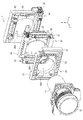
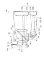
- FIG. 1 is an exploded perspective view illustrating a configuration of a lens shift mechanism according to an embodiment of the present disclosure.
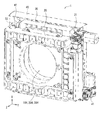
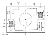
- FIG. 2 is a perspective view of a lens shift mechanism integrated by combining the members shown in FIG. 1.
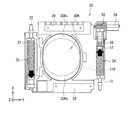
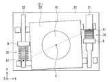
- FIG. 2 is a plan view of one operating unit shown in FIG. 1.
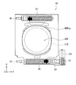
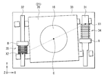
- FIG. 4 is a plan view of another operating unit shown in FIG. 1.
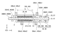
- FIG. 2 is a sectional view illustrating a configuration of a main shaft and peripheral members illustrated in FIG. 1.
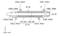
- FIG. 2 is a cross-sectional view illustrating a configuration of a countershaft illustrated in FIG. 1 and peripheral members thereof.
- FIG. 2 is a schematic plan view illustrating an operation mechanism of the lens shift mechanism illustrated in FIG. 1.
- FIG. 2 is a schematic plan view illustrating an operation mechanism of the lens shift mechanism illustrated in FIG.
- FIG. 2 is a schematic plan view illustrating an example of a positional relationship between a lens support unit and an operating unit illustrated in FIG. 1.
- FIG. 4 is a schematic plan view illustrating another example of the positional relationship between the lens support unit and the operating unit illustrated in FIG. 1.
- FIG. 4 is a schematic plan view illustrating another example of the positional relationship between the lens support unit and the operating unit illustrated in FIG. 1.
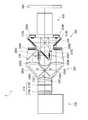
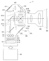
- 1 is a schematic diagram illustrating an example of a configuration of an optical system of a projection display device according to an embodiment of the present disclosure.
- FIG. 9 is a schematic diagram illustrating a configuration example of a light source optical system illustrated in FIG. 8.
- FIG. 2 is a schematic diagram illustrating another example of a configuration of an optical system of a projection display according to an embodiment of the present disclosure.
- Embodiment an example of a lens shift mechanism having an operating unit in which elastic bodies whose biasing directions are opposite to each other are arranged on a main shaft and a counter shaft
- Configuration of lens shift mechanism 1-2 Operation of lens shift mechanism 1-3.
- Action / effect 2 Application example 2-1.
- Application Example 1 Example of a projection display device using a reflection type spatial modulation element
- Application Example 2 Example of a projection display device using a transmission type spatial modulation element
- FIG. 1 is an exploded perspective view of a lens shift mechanism (lens shift mechanism 1) according to an embodiment of the present disclosure.
- FIG. 2 is a perspective view of the lens shift mechanism 1 in which the members shown in FIG.
- This lens shift mechanism 1 shifts a projection lens (projection lens 10) in a plane direction perpendicular to the optical axis in, for example, a projection display device (for example, projector 2, see FIG. 8) described later. , For adjusting the position of the projected image.
- the lens shift mechanism 1 includes a projection lens 10, a housing 11 that holds the projection lens 10, a lens support unit 20 that supports the projection lens 10 via the housing 11, and an operating unit 30 (first unit).
- the operating unit) and the operating unit 40 are combined in this order.
- the operating unit 30 holds, for example, the projection lens 10 having the optical axis in the Z-axis direction (specifically, for example, the lens support unit 20 to which the housing 11 is detachably fixed) in a direction perpendicular to the optical axis.
- the operating unit 40 is for moving the projection lens 10 having an optical axis in the Z-axis direction, for example, in another direction perpendicular to the optical axis (for example, the Y-axis direction), and extends in the Y-axis direction.
- the main shaft 41 and the sub shaft 42 are provided with a pair of elastic bodies (springs 44 and 45) that are parallel to the Y-axis direction and urge in opposite directions to each other (see FIG. 4).
- the lens support 20 has, for example, a substantially rectangular shape and a pedestal 21 provided with an opening 20H.
- the pedestal portion 21 is further provided with mounting portions 22 and 23 for connecting the lens support portion 20 to the operating portion 30.
- a housing 11 that holds the projection lens 10 is inserted into the opening 20H, and has a shape substantially the same as the outer diameter 11R of the housing 11, for example.
- the mounting portions 22 and 23 are provided on two opposing sides of the pedestal portion 21, respectively, and will be described in detail later.
- the mounting portions 22 and 23 are provided in housing portions 36 and 37 for housing the main shaft 31 and the sub shaft 32 of the operating portion 30, respectively. , For example, via screws (not shown).
- the lens support portion 20 is made of, for example, a material having a thickness in the Z-axis direction of 5 mm or more and 30 mm or less, for example, having a light shielding property.
- the lens support part 20 is formed by die casting using a non-ferrous metal such as aluminum (Al) or magnesium (Mg). Further, the lens support portion 20 may be formed using, for example, resin or carbon fiber.
- the operating unit 30 is for moving the projection lens 10 in one axis direction perpendicular to the optical axis.
- FIG. 3 illustrates an example of a planar configuration of the operating unit 30.
- the operating unit 30 moves the housing 11 holding the projection lens 10 together with the lens support unit 20 to, for example, an X-axis perpendicular to the optical axis (for example, the Z-axis direction) of the projection lens. It is for moving in the direction.
- the operating section 30 includes, for example, a main shaft 31 and a sub shaft 32, a pedestal portion 33 having a substantially rectangular shape and provided with an opening 30H, and a pair of springs 34 and 35 disposed on the main shaft 31 and the sub shaft. Having.
- the housing 11 holding the projection lens 10 is inserted into the opening 30H.
- the shape of the opening 30H is, for example, a circular shape (dotted line in FIG. 3) substantially the same as the outer diameter 11R of the housing 11. And has a margin region 30Rx in which the housing 11 can move in the X-axis direction.
- the pedestal portion 33 is further provided with accommodation portions 36 and 37 for accommodating the main shaft 31 and the sub shaft 32, respectively, and attachment portions 38 and 39 for connecting the operating portion 30 to the operating portion 40.
- the main shaft 31 and the sub shaft 32 are located on two opposite sides of the pedestal portion 33 such that the extending direction is parallel to the moving direction (X-axis direction) of the projection lens 10 by the operating portion 30 with the opening 30H interposed therebetween. It is arranged along. Specifically, the main shaft 31 is housed together with the spring 34 in a housing portion 36 arranged along one of two opposite sides of a pedestal portion 33 parallel to the moving direction of the projection lens 10 by the operating portion 30, It is fixed to the part 33.
- the sub shaft 32 is housed together with the spring 35 in a housing part 37 arranged along the other of the two opposite sides of the pedestal part 33 parallel to the moving direction of the projection lens 10 by the operating part 30 and fixed to the pedestal part 33. Have been.
- the spring 34 and the spring 35 are disposed on the main shaft 31 and the sub shaft 32 so as to have biases in directions opposite to each other, as indicated by arrows in FIG.
- the main shaft 31 is provided with a thread 31X (see FIG. 5A) at a part of the shaft, and a nut 51 is combined with the thread 31X.
- the mounting portions 38 and 39 are arranged opposite to each other along the two sides of the pedestal portion 33 different from the two sides on which the housing portions 36 and 37 are provided, with the opening 30H interposed therebetween.
- the attachment portions 38 and 39 are fastened to accommodation portions 46 and 47 for accommodating the main shaft 41 and the sub shaft 42 of the operating portion 40 via, for example, screws (not shown). Thereby, the lens support unit 20, the operating unit 30, and the operating unit 40 are integrated.
- the pedestal portion 33 is made of, for example, a material having a light-shielding property with a thickness in the Z-axis direction of 5 mm or more and 30 mm or less. Specifically, the pedestal portion 33 is formed by die casting using a non-ferrous metal such as aluminum (Al) or magnesium (Mg). The pedestal portion 33 may be formed using, for example, resin or carbon fiber. The accommodating portions 36 and 37 and the attaching portions 38 and 39 provided in the pedestal portion 33 may be formed using, for example, the same material as the pedestal portion 33, may be formed using a different material, and may be formed using a different material. When forming using, for example, it is preferable to use a sheet metal press part.
- the operating unit 40 is for moving the projection lens 10 in one axial direction perpendicular to the optical axis.
- FIG. 4 illustrates an example of a planar configuration of the operating unit 40.
- the operating unit 40 moves the housing 11 holding the projection lens 10 together with the lens support unit 20 and the operating unit 30, for example, perpendicularly to the optical axis (for example, the Z-axis direction) of the projection lens.
- the operating portion 40 includes, for example, a main shaft 41 and a sub shaft 42, a pedestal portion 43 having a substantially rectangular shape and provided with an opening 40H, and a pair of springs 44 and 45 disposed on the main shaft 41 and the sub shaft 42.
- the housing 40 holding the projection lens 10 is inserted into the opening 40H.
- the shape of the opening 40H is, for example, substantially the same as the outer diameter 11R of the housing 11 (dotted line in FIG. 4).
- the pedestal portion 43 is further provided with accommodation portions 46 and 47 for accommodating the main shaft 41 and the sub shaft 42, respectively.
- the main shaft 41 and the sub-shaft 42 are located on two opposing sides of the pedestal 43 so that the extending direction thereof is parallel to the moving direction (Y-axis direction) of the projection lens 10 by the operating unit 40 with the opening 40H interposed therebetween. It is arranged along. Specifically, the main shaft 41 is housed together with the spring 44 in a housing 46 arranged along one of two opposite sides of a pedestal 43 parallel to the direction of movement of the projection lens 10 by the operating unit 40, It is fixed to the part 43.
- the sub shaft 42 is housed together with a spring 45 in a housing part 47 arranged along the other of the two opposite sides of the pedestal part 43 parallel to the moving direction of the projection lens 10 by the operating part 40, and is fixed to the pedestal part 43. Have been.
- the spring 44 and the spring 45 are disposed on the main shaft 41 and the sub shaft 42 so as to be biased in directions opposite to each other, as indicated by arrows in FIG.
- the main shaft 41 is provided with a thread 41X (see FIG. 5A) at a part of the shaft, and a nut 52 is combined with the thread 41X.
- the pedestal portion 43 is made of, for example, a material having a thickness in the Z-axis direction of 5 mm or more and 30 mm or less, for example, having a light-shielding property. Specifically, the pedestal portion 43 is formed by die casting using a non-ferrous metal such as aluminum (Al) or magnesium (Mg). The pedestal 43 may be formed using, for example, resin or carbon fiber. The accommodating portions 46 and 47 provided in the pedestal portion 43 may be formed using, for example, the same material as the pedestal portion 43, may be formed using a different material, or may be formed using a different material. For example, it is preferable to use a sheet metal pressed part.
- FIG. 5A illustrates a cross-sectional configuration of the main shafts 31 and 41 and its peripheral members
- FIG. 5B illustrates a cross-sectional configuration of the sub-shafts 32 and 42 and its peripheral members.
- the main shaft 31 and the sub shaft 32 provided in the operating unit 30 and the reference numerals of the peripheral members will be described as representatives.
- the main shaft 31 is for guiding the moving direction of the projection lens 10 in one axis direction (here, the X axis direction).
- the main shaft 31 is formed of, for example, a material having high strength and high wear resistance during sliding.
- the main shaft 31 is formed of stainless steel (SUS), brass, or the like.
- the main shaft 31 has a diameter of, for example, 5 ⁇ or more and 10 ⁇ or less.
- the length of the main shaft 31 is preferably longer than the longitudinal direction of the opening 30H provided with the blank area 30Rx, for example, and has a margin with respect to the operating range.
- the main shaft 31 is provided with a coil-shaped spring 34, for example. Specifically, the main shaft 31 passes through the space inside the coiled spring 34.
- the main shaft 31 is partially provided with the thread 31X, and the nut 51 is attached to the thread 31.
- a gear 55 is attached to one end of the main shaft 31, and a motor 56 is connected to the gear 55. The driving of the motor 56 causes the gear 55 to rotate, and the gear 55 is attached. The main shaft 31 rotates together.
- the housing 36 is for housing the main shaft 31 and the spring 34 and for fixing the main shaft 31 to the pedestal 33.
- the accommodation section 36 has, for example, a fixing section 36A fixed to the pedestal section 33, and a lid section 36B covering the fixing section 36A, and the lid section 36B slides with respect to the fixing section 36A.
- the fixing portion 36A and the lid portion 36B have openings 36AH1, 36AH2, 36BH1, and 36BH2 that are larger than the diameter of the main shaft 31 on respective side surfaces facing the sliding direction (for example, the X-axis direction) of the lid portion 36B. .
- the main shaft 31 passes through the openings 36AH1, 36AH2, 36BH1, and 36BH2 in the order of, for example, the opening 36AH1, the opening 36BH1, the opening 36AH2, and the opening 36BH2 from the side of the gear 55 attached to the main shaft 31 (rightward in FIG. 5A).
- the lid 36B can operate along the main shaft 31.
- a fixing groove 36X in which a nut 51 attached to the main shaft 31 is fitted is provided at a predetermined position inside the lid 36B.
- two fastening portions 36Ax1 and 36Ax2 are provided, and are fixed to the pedestal portion 33 by, for example, screws (not shown).
- two fastening portions 36Bx1 and 36Bx2 to which an attachment portion (for example, the attachment portion 22) of the lens support portion 20 is fastened are provided.
- the sub-shaft 32 is for maintaining the moving direction of the projection lens 10 in one axis direction (here, the X-axis direction) by combining with the main shaft 31.
- the sub shaft 32 is formed of, for example, a material having high strength and high wear resistance during sliding.
- the sub shaft 32 is formed of stainless steel (SUS), brass, or the like.
- the sub shaft 32 has a diameter of, for example, 5 ⁇ or more and 10 ⁇ or less.
- the length of the sub shaft 32 is preferably longer than the longitudinal direction of the opening 30H provided with the blank area 30Rx, for example, and has a margin with respect to the operating range.
- the sub-shaft 32 is provided with, for example, a coiled spring 35. Specifically, the sub shaft 32 penetrates the space inside the coiled spring 35.
- the housing 37 is for housing the sub shaft 32 and the spring 35 and for fixing the sub shaft 32 to the pedestal 33.
- the accommodation portion 37 has, for example, a fixing portion 37A fixed to the pedestal portion 33, and a lid portion 37B covering the fixing portion 37A, and the lid portion 37B slides with respect to the fixing portion 37A.
- the fixing portion 37A and the lid portion 37B are provided with openings 37AH1, 37AH2, 37BH1, and 37BH2 that are larger than the diameter of the sub-shaft 32 on the respective side surfaces facing the sliding direction (for example, the X-axis direction) of the lid portion 37B. I have.
- the sub shaft 32 passes through the openings 37AH1, 37AH2, 37BH1, and 37BH2 in the order of, for example, the opening 37BH1, the opening 37AH1, the opening 37BH2, and the opening 37AH2 from the right in FIG. 5B. Operation is possible along the sub shaft 32.
- two fastening portions 37Ax1 and 37Ax2 are provided, and are fixed to the pedestal portion 33 by, for example, screws (not shown).
- two fastening portions 37Bx1 and 37Bx2 to which an attachment portion (for example, the attachment portion 23) of the lens support portion 20 is fastened are provided.
- the accommodating portion 46 for accommodating the main shaft 41 and the spring 44 and the accommodating portion 47 for accommodating the sub shaft 42 and the spring 45 are provided in the guide direction of the projection lens 10 by the main shaft 41 and the sub shaft 42 (here, Except for the difference in the (Y-axis direction), it has the same configuration as the above-described main shaft 31 and sub-shaft 32 and the peripheral members thereof, and thus the description is omitted.
- the lens support portion 20 is configured such that the attachment portion 22 provided on the pedestal portion 21 is attached to the fastening portions 36Bx1 and 36Bx2 of the lid portion 36B of the accommodation portion 36 that accommodates the main shaft 31 of the operating portion 30, and the attachment portion 23 Are respectively fastened to the fastening portions 37Bx1 and 37Bx2 of the lid 37B of the housing portion 37 that houses the sub shaft 32 of the operating portion 30 by, for example, screws (not shown).
- the mounting section 38 provided on the pedestal section 33 is fastened to the fastening sections 46Bx1, 46x2 and the mounting section 39 of the lid 46B of the housing section 46 that houses the main shaft 41 of the operating section 40.
- Each of the fastening portions 47Bx1 and 47Bx2 of the lid portion 47B of the housing portion 47 that houses the sub shaft 42 of the operating portion 40 is fastened by, for example, a screw (not shown).
- a screw not shown
- the operation mechanism of the lens shift mechanism will be described by taking as an example the movement of the lens support unit 20 using the main shaft 31 and the sub shaft 32 provided in the operating unit 30.
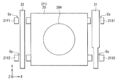
- FIG. 6A is a plan view schematically showing the main shaft 31 and the sub shaft 32 and the lens support portion 20 in a state where there is no urging by the elastic body.
- the extension parts 21X1, 21X2, 21Y1, 21Y2 provided at the four corners of the pedestal part 21 of the lens support part 20 respectively cover the lids 36B, 36B of the operating part 30 fastened to the attachment parts 22, 23 of the lens support part 20, respectively.
- the positions correspond to the fastening portions 36Bx1, 36Bx2, 37Bx1, 37Bx2 provided in 37B.
- the extension portion 21X1 corresponds to the fastening portion 36Bx1
- the extension portion 21X2 corresponds to the fastening portion 36Bx2
- the extension portion 21Y1 corresponds to the fastening portion 37Bx1
- the extension portion 21Y2 corresponds to the fastening portion 37B2.
- a gap Gx is provided between the extension portions 21X1, 21X2 and the main shaft 31
- a gap Gy is provided between the extension portions 21Y1, 21Y2 and the sub shaft 32, respectively.
- the gaps Gx and Gy are clearances for moving the lens support unit 20 in the X-axis direction by the operating unit 30.
- the gap Gx corresponds to a difference between the diameter of the main shaft 31 and the diameters of the openings 36AH1, 36AH2, 36BH1, and 36BH2 provided in the fixing portion 31A of the housing portion 36 and the lid portion 36B.
- the gap Gy corresponds to a difference between the diameter of the sub shaft 32 and the diameters of the openings 37AH1, 37AH2, 37BH1, and 37BH2 provided in the fixing portion 32A and the lid portion 37B of the housing portion 37.
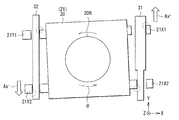
- FIG. 6B is a plan view schematically showing a state in which the springs 34 and 35 apply biases in directions opposite to each other.
- the main shaft 31 and the sub shaft 32 are each fixed to the pedestal portion 33 so that their positions with respect to the operating portion 30 (the pedestal portion 33) do not change. Therefore, when the main shaft 31 is rotated, the nut 51 attached to the thread 31X provided on the main shaft 31 moves in a predetermined direction on the X axis (for example, the left direction (negative direction) in FIG. 5A). Accordingly, the lids 36B, 37B and the lens support 20 fastened to the lids 36B, 37B move in the same direction as the nut 51 on the X axis.
- the distance lx between the side surface of the fixed portion 36A in which the spring 34 is accommodated and the nut 51 changes.
- the spring 34 is deformed, and the magnitude of the bias applied to the nut 51 on the working side changes.
- the magnitude of the bias applied to the side surface of the operating side lid 37B of the spring 35 combined with the sub shaft 32 also changes. Therefore, as shown in FIG. 6B, the right lens support portion 20 on the paper surface fastened to the main shaft 31 side is in the direction of the arrow Ax + (positive direction of the X axis), and the left lens support member fastened to the sub shaft 32 side.
- the base portion 21 of the lens support portion 20 is rotated in ⁇ direction about the projection lens 10 .
- the main shaft 31 and the extension portions 21X1, 21X2 specifically, the openings 36AH1, 36AH2, 36BH1, 36BH2
- the sub shaft 32 and the extension portions 21Y1, 21Y2 specifically, the openings 37AH1, 37AH2, 37BH1, 37BH2 come into contact with each other in the circles shown in FIG. 6B, thereby reducing the backlash in the X-axis direction due to the clearances (gap Gx, Gy).
- FIG. 7A schematically illustrates an example of a positional relationship between the lens support unit 20 and the operation unit 30.
- the member A disposed on the main shaft 31 of the operating unit 30 corresponds to the side surface (A in FIG. 5A) of the fixed unit 36A in contact with the spring 34
- the member B disposed on the sub shaft 32 of the operating unit 30 Corresponds to the side surface (B in FIG. 5B) of the fixing portion 37A in contact with the spring 35.
- the lens shift mechanism 1 of the present embodiment by rotating the main shaft 31 fixed to the pedestal portion 33, the nut 51 combined with the main shaft 31 moves together with the lid portion 36B, and the spring 34 The distance lx between the nut 51 and the side surface of the fixing portion 36A that defines the length of the fixing portion 36A changes. As a result, the spring 34 is deformed, and the magnitude (urging force) of the urging applied to the side surfaces of the nut 51 and the fixing portion 36A changes.
- the cover 37B of the sub shaft 32 which is fastened to the pedestal 21 of the lens support 20, also moves in accordance with the movement of the cover 36B of the main shaft 31.
- FIG. 7B shows a state in which the lens support unit 20 is moved below the main shaft 31 and the sub shaft 32 in FIG. 7B
- FIG. 7C shows a state in which the lens support unit 20 is the reverse of FIG. 5 shows a state where the main shaft 31 and the sub shaft 32 are moved above.
- FIG. 7B in a state where the lens support portion 20 is moved downward, the spring 34 disposed on the main shaft 31 is compressed, the urging force (repulsive force) is high, and the sub shaft is The spring 35 disposed at 32 extends, and the urging force (repulsive force) is low.
- the force balance between the spring 34 and the spring 35 changes in the middle. If the total force including gravity is exchanged in the vertical direction during the change in the force balance between the springs 34 and 35, the direction pressed by the springs 34 and 35 changes, and at that moment, the lens support 20 May become unstable.
- the spring 34 and the spring 34 are so set that the urging force of one of the spring 34 and the spring 35 is always high regardless of the position of the lens support 20 on the main shaft 31. It is desirable to set the strength of the spring 35.
- the biasing force of the spring 34 provided on the main shaft 31 and the spring 35 provided on the sub shaft 32 is set so as to satisfy the following expression (1).
- the lens support 20 on the right side of the paper is inclined upward and the lens support 20 on the left of the paper is inclined downward regardless of the position of the lens support 20 with respect to the main shaft 31. In this state, the movement of the lens support 20 is stabilized.
- Equation 1 Minimum urging force of spring 34> Maximum urging force of spring 35 + Gravity of entire moving member (1)
- the entire moving member in the above equation (1) refers to all members constituting the lens support portion 20 including the projection lens 10 and the housing 11. Further, in the above equation (1), the spring 34 provided on the main shaft 31 always has a high urging force. However, the present invention is not limited to this, and the spring 35 provided on the sub shaft 32 always has a high urging force. May be provided.
- the positions where the biases of the spring 34 and the spring 35 are applied include a point where the bias of the spring 34 is applied (for example, the biasing point X1 in FIG. 7A) and a point where the bias of the spring 35 is applied (for example). It is preferable that the adjustment is performed so that the optical axis center C of the projection lens 10 is arranged near a straight line connecting the bias point X2) of FIG. 7A. Thus, the rotation center of the rotation of the lens support 20 due to the bias of the springs 34, 34 substantially coincides with the optical axis of the projection lens 10.
- the projection lens is formed point-symmetrically with respect to the center of the optical axis, even if the projection lens rotates about the center of the optical axis, it does not affect the projected image. Therefore, even if the biasing force applied from the springs 34 and 35 fluctuates, stable image projection can be performed.
- a projector that projects an image on a screen is required to have a function of adjusting a position of an image projected on the screen to a position desired by a user.
- a lens shift device that adjusts an image position by shifting in a vertical direction (horizontal direction and vertical direction) is mounted.
- the projector displays an image enlarged by the projection lens on the screen, a minute movement or rattling of the projection lens is converted into a large movement of the projection image on the screen.
- a liquid crystal panel having a size of 1 is used to project an image having a size of 300 on a screen
- the movement of the projection lens is displayed as a projection image enlarged 100 times or more. Moves by 0.1 mm or more on the screen. For this reason, a projector is required to have a stable projection image position, and is required to hold a projection lens at a precise position.
- the lens shift device is provided with a clearance for operating the projection lens, and this clearance causes play. For this reason, in order to hold the projection lens at a precise position, there is a demand for the development of a method for eliminating the backlash of the projection lens by the lens shift device.
- the first problem is that when a load such as vibration or impact exceeding the frictional force occurs, the position of the projection lens may move, and it may not be possible to maintain an accurate position. Setting of frictional force is required.
- the second problem is that when driving the projection lens, it is driven with a large force exceeding the frictional force, so that the load on a driving mechanism such as a motor for moving the projection lens becomes large, and the moving speed of the projection lens becomes slow. There is a disadvantage that the driving noise increases.
- the projection lens 10 held in the housing 11 is moved in one axial direction (for example, the X-axis direction) perpendicular to the optical axis (for example, the Z-axis direction).
- a main shaft 31 and a sub-shaft 32 that also extend in one axis direction (X-axis direction) are arranged opposite to each other with the casing 11 interposed therebetween.
- the springs 34 and 35 for urging in the opposite directions are combined. This makes it possible to reduce the backlash in the plane (XY plane) direction perpendicular to the optical axis (Z-axis direction).
- the X-axis which is perpendicular to the optical axis (for example, the Z-axis direction) of the projection lens 10 of the lens support unit 20 that supports the housing 11 that holds the projection lens 10
- a main shaft 31 and a sub shaft 32 extending in the X-axis direction are provided with springs 34 and 35 for urging the housing 11 in opposite directions, respectively.
- the operation was performed using the operating unit 30. Thereby, the backlash in the direction (for example, the XY plane) perpendicular to the optical axis (Z-axis direction) is reduced, and the stability of the position of the image projected from the projection lens 10 can be improved.
- the casing 11 is disposed to face the space therebetween, and springs 44 and 45 for urging in opposite directions to each other are combined. Since the operating unit 40 having the main shaft 41 and the sub shaft 42 to be extended is provided, and the lens supporting unit 20 is moved in the Y-axis direction by using the operating unit 40, the projection lens 10 can be moved in the XY plane without rattling. It can be moved freely.
- the lens shift mechanism 1 of the present embodiment compared with the above-described lens shift mechanism, it is possible to reduce the backlash in the direction perpendicular to the optical axis without applying a load to the support member and the like of the projection lens. Can be. Therefore, a driving mechanism such as a lens support unit and a motor for moving the projection lens (in the present embodiment, the lens support unit 20 and, for example, the main shaft 31 and the main shaft 41 provided in the operation unit 30 and the operation unit 40). It is possible to reduce the load on the motors 56 and 58 and the gears 55 and 57 for rotation. Therefore, the reliability of the lens shift mechanism 1 can be improved. Furthermore, it is possible to improve the quietness.
- a driving mechanism such as a lens support unit and a motor for moving the projection lens (in the present embodiment, the lens support unit 20 and, for example, the main shaft 31 and the main shaft 41 provided in the operation unit 30 and the operation unit 40). It is possible to reduce the load on the motors 56 and 58 and the gears 55 and 57
- FIG. 8 exemplifies a reflective 3LCD type projection display device (projector 2) that performs light modulation by a reflective liquid crystal panel.
- the projector 2 includes a light source device 100, an illumination optical system 200, an image forming unit 300, and a projection optical system 400 (projection optical system).
- the projector 2 of the present disclosure can be applied to a projector using a transmissive liquid crystal panel or a digital micro-mirror device (DMD) instead of the reflective liquid crystal panel.
- DMD digital micro-mirror device
- the light source device 100 includes a phosphor wheel 110 (wavelength conversion unit), a light source unit 120 that emits excitation light or laser light, lenses 130 to 160, a dichroic mirror 170, and a reflection mirror 180. And a diffusion plate 190.
- the phosphor wheel 110 has a configuration in which a phosphor layer 112 is provided on a substrate 111 on a disk, for example, and is rotatably supported by a shaft J113.
- the diffusion plate 190 is rotatably supported by a shaft J191.
- the light source unit 120 has a first laser group 120A and a second laser group 120B.
- the first laser group 120A includes a semiconductor laser element 121A that oscillates excitation light (for example, a wavelength of 445 nm or 455 nm), and the second laser group 120B includes a semiconductor laser element 121B that oscillates blue laser light (for example, a wavelength of 465 nm). It is one in which a plurality are arranged.
- the excitation light oscillated from the first laser group 120A is referred to as EL1
- the blue laser light (hereinafter, simply referred to as blue light) oscillated from the second laser group 120B is referred to as EL2.
- the illumination optical system 200 includes, for example, a fly-eye lens 210 (210A, 210B), a polarization conversion element 220, a lens 230, dichroic mirrors 240A, 240B, and reflection mirrors 250A, 250B from a position close to the light source device 100A. It has lenses 260A and 260B, a dichroic mirror 270, and polarizing plates 280A to 280C.
- the fly-eye lens 210 (210A, 210B) is for homogenizing the illuminance distribution of the white light from the light source device 100A.
- the polarization conversion element 220 functions to align the polarization axis of the incident light in a predetermined direction. For example, light other than P-polarized light is converted to P-polarized light.
- the lens 230 condenses the light from the polarization conversion element 220 toward the dichroic mirrors 240A and 240B.
- the dichroic mirrors 240A and 240B selectively reflect light in a predetermined wavelength range and selectively transmit light in other wavelength ranges.
- the dichroic mirror 240A mainly reflects red light in the direction of the reflection mirror 250A.
- the dichroic mirror 240B mainly reflects blue light toward the reflection mirror 250B. Therefore, the green light mainly passes through both the dichroic mirrors 240A and 240B and travels toward the reflective polarizing plate 310C (described later) of the image forming unit 300.
- the reflecting mirror 250A reflects light (mainly red light) from the dichroic mirror 240A toward the lens 260A, and the reflecting mirror 250B reflects light (mainly blue light) from the dichroic mirror 240B toward the lens 260B. I do.
- the lens 260A transmits light (mainly red light) from the reflection mirror 250A and collects the light on the dichroic mirror 270.
- the lens 260B transmits the light (mainly blue light) from the reflection mirror 250B and collects the light on the dichroic mirror 270.
- the dichroic mirror 270 selectively reflects green light and selectively transmits light in other wavelength ranges.
- the red light component of the light from the lens 260A is transmitted.
- the green light component is reflected toward the polarizing plate 280C.
- Each of the polarizing plates 280A to 280C includes a polarizer having a polarization axis in a predetermined direction. For example, when the light is converted into P-polarized light by the polarization conversion element 220, the polarizing plates 280A to 280C transmit P-polarized light and reflect S-polarized light.
- the image forming unit 300 includes the reflective polarizing plates 310A to 310C, the reflective liquid crystal panels 320A to 320C (light modulation elements), and the dichroic prism 330.
- the reflective polarizing plates 310A to 310C transmit light having the same polarization axis (for example, P-polarized light) as the polarization axis of the polarized light from the polarizing plates 280A to 280C, and transmit light having other polarization axes (S-polarized light). It is reflective. Specifically, the reflective polarizing plate 310A transmits the P-polarized red light from the polarizing plate 280A in the direction of the reflective liquid crystal panel 320A. The reflective polarizer 310B transmits the P-polarized blue light from the polarizer 280B in the direction of the reflective liquid crystal panel 320B.
- P-polarized light for example, P-polarized light
- the reflective polarizer 310C transmits the P-polarized green light from the polarizer 280C in the direction of the reflective liquid crystal panel 320C.
- the P-polarized green light that has passed through both the dichroic mirrors 240A and 240B and entered the reflective polarizing plate 310C passes through the reflective polarizing plate 310C and enters the dichroic prism 330 as it is.
- the reflective polarizing plate 310A reflects the S-polarized red light from the reflective liquid crystal panel 320A and makes the red light enter the dichroic prism 330.
- the reflective polarizing plate 310B reflects the S-polarized blue light from the reflective liquid crystal panel 320B and makes the blue light enter the dichroic prism 330.
- the reflective polarizing plate 310C reflects the S-polarized green light from the reflective liquid crystal panel 320C and makes the green light enter the dichroic prism 330.
- the reflective liquid crystal panels 320A to 320C perform spatial modulation of red light, blue light, or green light, respectively.
- the dichroic prism 330 combines the incident red light, blue light, and green light and emits the light toward the projection optical system 400.
- the projection optical system 400 has, for example, a plurality of lenses and the like, not shown.
- the projection optical system 400 enlarges the light emitted from the image forming unit 300 and projects the light on the screen 500.
- the lens shift mechanism 1 in the above embodiment is applied to the projection optical system 400.
- FIG. 10 is a schematic diagram illustrating an example of the configuration of a transmission type 3LCD type projection display device (projector 3) that performs light modulation by a transmission type liquid crystal panel.
- the projector 3 includes, for example, the light source device 100, an image generation system 600 having an illumination optical system 610 and an image generation unit 630, and a projection optical system 400. Note that the light source device 100 has the same configuration as the light source device 100 in Application Example 1 described above.
- the illumination optical system 610 includes, for example, an integrator element 611, a polarization conversion element 612, and a condenser lens 613.
- the integrator element 611 includes a first fly-eye lens 611A having a plurality of microlenses arranged two-dimensionally and a second fly-eye having a plurality of microlenses arranged one by one corresponding to each of the microlenses.
- An eye lens 611B is included.
- Light (parallel light) incident on the integrator element 611 from the light source device 100 is divided into a plurality of light fluxes by the microlenses of the first fly-eye lens 611A, and is respectively coupled to the corresponding microlenses of the second fly-eye lens 611B. Imaged.
- Each of the micro lenses of the second fly-eye lens 611B functions as a secondary light source, and irradiates the polarization conversion element 612 with a plurality of parallel lights having the same brightness as incident light.
- the integrator element 611 has a function of adjusting incident light emitted from the light source device 100 to the polarization conversion element 612 into a uniform luminance distribution as a whole.
- the polarization conversion element 612 has a function of aligning the polarization state of incident light that enters via the integrator element 611 and the like.
- the polarization conversion element 612 emits outgoing light including the blue light Lb, the green light Lg, and the red light Lr via, for example, the lens 150 disposed on the emission side of the light source device 100.
- the illumination optical system 610 further includes a dichroic mirror 614 and a dichroic mirror 615, a mirror 616, a mirror 617 and a mirror 618, a relay lens 619 and a relay lens 620, a field lens 621R, a field lens 621G and a field lens 621B, and an image generation unit 630.
- a dichroic mirror 614 and a dichroic mirror 615 a mirror 616, a mirror 617 and a mirror 618
- a relay lens 619 and a relay lens 620 a field lens 621R, a field lens 621G and a field lens 621B
- an image generation unit 630 a field lens 621R, a field lens 621G and a field lens 621B
- liquid crystal panels 631R, 631G and 631B and a dichroic prism 632.
- the dichroic mirror 614 and the dichroic mirror 615 have a property of selectively reflecting color light in a predetermined wavelength range and transmitting light in other wavelength ranges.
- the dichroic mirror 614 selectively reflects the red light Lr.
- the dichroic mirror 615 selectively reflects the green light Lg among the green light Lg and the blue light Lb transmitted through the dichroic mirror 614.
- the remaining blue light Lb passes through the dichroic mirror 615. Thereby, the light (white light Lw) emitted from the light source device 100 is separated into a plurality of color lights of different colors.
- the separated red light Lr is reflected by the mirror 616, is collimated by passing through the field lens 621R, and then enters the liquid crystal panel 631R for modulation of red light.
- the green light Lg is collimated by passing through the field lens 621G, and then enters the liquid crystal panel 631G for modulating the green light.
- the blue light Lb passes through the relay lens 619 and is reflected by the mirror 617, and further passes through the relay lens 620 and is reflected by the mirror 618.
- the blue light Lb reflected by the mirror 618 is collimated by passing through the field lens 621B, and then enters the liquid crystal panel 631B for modulating the blue light Lb.
- the liquid crystal panels 631R, 631G and 631B are electrically connected to a signal source (not shown) (not shown) for supplying an image signal including image information.
- the liquid crystal panels 631R, 631G, and 631B modulate the incident light for each pixel based on the supplied image signals of each color to generate a red image, a green image, and a blue image, respectively.
- the modulated light of each color (formed image) enters the dichroic prism 632 and is synthesized.
- the dichroic prism 632 superimposes and combines the light of each color incident from three directions, and emits the light toward the projection optical system 400.
- the projection optical system 400 has, for example, a plurality of lenses and the like, not shown.
- the projection optical system 400 enlarges the light emitted from the image generation system 600 and projects it on the screen 500.
- the lens shift mechanism 1 in the above embodiment is applied to the projection optical system 400.
- the optical members constituting the projectors 2 and 3 have been specifically described. However, it is not necessary to provide all the optical members, and other optical members may be further provided.
- an example of a projector using a reflective or transmissive liquid crystal panel (LCD) as a light modulation element has been described.
- the present disclosure discloses a digital micromirror device (DMD: Digital @ Micro-mirror). Device) or the like.
- the present disclosure may have the following configurations. According to the present technology of the following configuration, while extending in a uniaxial direction perpendicular to the optical axis of the projection lens, a pair of main shafts and sub-shafts disposed opposite to each other with a casing holding the projection lens therebetween. Since the position of the projection lens is adjusted using an operating portion that is a combination of a pair of elastic bodies that are parallel to one axis direction and are biased in opposite directions, the projection lens in a plane direction perpendicular to the optical axis. The rattling is reduced. Therefore, the stability of the position of the image projected from the projection lens can be improved.
- the effects described here are not necessarily limited, and may be any of the effects described in the present disclosure.
- a projection lens A housing for holding the projection lens, An operating unit that moves the casing in one axial direction perpendicular to the optical axis of the projection lens, The operating section, Extending in the uniaxial direction, a pair of main shaft and sub shaft arranged opposite the housing between, A lens shift mechanism that is provided on each of the main shaft and the sub shaft, and has a pair of elastic bodies that are parallel to the uniaxial direction and urge in opposite directions to each other.
- the lens shift mechanism according to (1) or (2), wherein (4) Among the above (1) to (3), a straight line connecting a first bias point and a second bias point to which the bias of the pair of elastic bodies is applied passes near the optical axis of the projection lens.
- the lens shift mechanism according to any one of the above.
- the operating section further houses a first housing section that houses the main shaft and one elastic body provided on the main shaft, and houses the sub shaft and another elastic body provided on the sub shaft.
- the lens shift mechanism according to any one of (1) to (4), further including a pedestal provided with a second housing portion and an opening into which the casing is inserted.
- the first housing section has a first fixing section fixed to the pedestal section, and a first lid section movable in the uniaxial direction
- the (1) includes, as the operating unit, a first operating unit that moves the casing in one direction and a second operating unit that moves the casing in another direction different from the one direction.
- the lens shift mechanism according to any one of (1) to (7).
- the first operating part and the second operating part are respectively a first housing part that houses the main shaft and the one elastic body, and a second housing that houses the counter shaft and the other elastic body. Part and a pedestal part having an opening into which the casing is inserted, The opening provided in the pedestal portion of the first operating section has a blank area in the one direction,
- the first housing section has a first fixing section fixed to the pedestal section, and a first lid section movable in the uniaxial direction
- the second storage section includes a second fixing section fixed to the pedestal section, and a second lid section movable in the uniaxial direction
- a lens support unit that holds the housing is fastened to the first lid unit and the second lid unit of the first operating unit;
- the lens shift mechanism according to (9) or (10), wherein the first operating unit is fastened to the first lid and the second lid of the second operating unit.
- the optical axis direction of the projection lens is a Y-axis direction, the one direction is an X-axis direction, and the other direction is a Y-axis direction, according to any one of (8) to (11).
- Lens shift mechanism is a Y-axis direction, the one direction is an X-axis direction, and the other direction is a Y-axis direction, according to any one of (8) to (11).
- Lens shift mechanism is a Y-axis direction, the
- a light source section An image forming unit having a plurality of optical units including a light modulation element that modulates light from the light source unit based on an input video signal, A projection unit that projects the image light generated by the image forming unit, The projection unit, A projection lens, A housing for holding the projection lens, An operating unit that moves the casing in one axial direction perpendicular to the optical axis of the projection lens, The operating section, Extending in the uniaxial direction, a pair of main shaft and sub shaft arranged opposite the housing between, A projection display device, comprising: a pair of elastic bodies disposed on each of the main shaft and the sub shaft, and urged in parallel to the uniaxial direction and in opposite directions.
Landscapes
- Physics & Mathematics (AREA)
- General Physics & Mathematics (AREA)
- Optics & Photonics (AREA)
- Projection Apparatus (AREA)
- Lens Barrels (AREA)
- Overhead Projectors And Projection Screens (AREA)
Priority Applications (4)
| Application Number | Priority Date | Filing Date | Title |
|---|---|---|---|
| JP2020540191A JP7327407B2 (ja) | 2018-08-31 | 2019-08-02 | レンズシフト機構および投射型表示装置 |
| US17/265,558 US11262645B2 (en) | 2018-08-31 | 2019-08-02 | Lens shift mechanism and projection display apparatus |
| EP19853917.3A EP3845965B1 (en) | 2018-08-31 | 2019-08-02 | Lens shift mechanism and projection display device |
| CN201980054548.5A CN112639608B (zh) | 2018-08-31 | 2019-08-02 | 透镜移位机构和投影显示装置 |
Applications Claiming Priority (2)
| Application Number | Priority Date | Filing Date | Title |
|---|---|---|---|
| JP2018162440 | 2018-08-31 | ||
| JP2018-162440 | 2018-08-31 |
Publications (1)
| Publication Number | Publication Date |
|---|---|
| WO2020044955A1 true WO2020044955A1 (ja) | 2020-03-05 |
Family
ID=69643580
Family Applications (1)
| Application Number | Title | Priority Date | Filing Date |
|---|---|---|---|
| PCT/JP2019/030487 Ceased WO2020044955A1 (ja) | 2018-08-31 | 2019-08-02 | レンズシフト機構および投射型表示装置 |
Country Status (6)
| Country | Link |
|---|---|
| US (1) | US11262645B2 (enExample) |
| EP (1) | EP3845965B1 (enExample) |
| JP (1) | JP7327407B2 (enExample) |
| CN (1) | CN112639608B (enExample) |
| TW (1) | TWI820176B (enExample) |
| WO (1) | WO2020044955A1 (enExample) |
Cited By (2)
| Publication number | Priority date | Publication date | Assignee | Title |
|---|---|---|---|---|
| WO2021190065A1 (zh) * | 2020-03-25 | 2021-09-30 | 深圳光峰科技股份有限公司 | 一种透镜调节装置 |
| JP2022180032A (ja) * | 2021-05-24 | 2022-12-06 | パナソニックIpマネジメント株式会社 | レンズ保持装置および投写型映像表示装置 |
Families Citing this family (3)
| Publication number | Priority date | Publication date | Assignee | Title |
|---|---|---|---|---|
| CN112578611B (zh) * | 2019-09-30 | 2024-10-29 | 深圳光峰科技股份有限公司 | 镜头调节装置及投影设备 |
| JP7517132B2 (ja) * | 2020-12-16 | 2024-07-17 | 株式会社Jvcケンウッド | プロジェクタ |
| CN116009267B (zh) * | 2022-12-09 | 2024-04-26 | 西安炬光科技股份有限公司 | 光斑整形装置及激光加工设备 |
Citations (8)
| Publication number | Priority date | Publication date | Assignee | Title |
|---|---|---|---|---|
| JP2005157370A (ja) * | 2003-11-27 | 2005-06-16 | Samsung Electronics Co Ltd | プロジェクタの投射レンズシフト調整装置 |
| JP2006301424A (ja) * | 2005-04-22 | 2006-11-02 | Seiko Epson Corp | プロジェクタ |
| JP2008287292A (ja) * | 2008-08-20 | 2008-11-27 | Sanyo Electric Co Ltd | 投写型映像表示装置 |
| JP2009175353A (ja) * | 2008-01-23 | 2009-08-06 | Seiko Epson Corp | プロジェクタ |
| JP2010033095A (ja) * | 2009-11-18 | 2010-02-12 | Sanyo Electric Co Ltd | レンズシフト機構及び投写型映像表示装置 |
| JP2010097019A (ja) | 2008-10-17 | 2010-04-30 | Cosina Co Ltd | 光学機器のレンズシフト装置 |
| JP2017068179A (ja) * | 2015-10-02 | 2017-04-06 | キヤノン株式会社 | レンズシフト機構 |
| JP2018162440A (ja) | 2017-03-27 | 2018-10-18 | Jsr株式会社 | 組成物およびその用途 |
Family Cites Families (15)
| Publication number | Priority date | Publication date | Assignee | Title |
|---|---|---|---|---|
| JP3754392B2 (ja) * | 2002-04-24 | 2006-03-08 | 三洋電機株式会社 | レンズシフト機構及び投写型映像表示装置 |
| JP3963879B2 (ja) * | 2003-08-04 | 2007-08-22 | 三洋電機株式会社 | レンズシフト機構及び投写型映像表示装置 |
| JP4309736B2 (ja) * | 2003-10-01 | 2009-08-05 | オリンパス株式会社 | 振動波リニアモータ |
| JP5238130B2 (ja) * | 2005-12-12 | 2013-07-17 | 株式会社Suwaオプトロニクス | 投射型表示装置 |
| JP4045290B2 (ja) * | 2006-05-19 | 2008-02-13 | シャープ株式会社 | 撮像装置 |
| JP4203829B2 (ja) | 2006-09-29 | 2009-01-07 | ソニー株式会社 | レンズシフト機構 |
| JP4937883B2 (ja) * | 2007-11-09 | 2012-05-23 | Hoya株式会社 | 光学要素位置制御機構 |
| TWI456252B (zh) * | 2009-08-10 | 2014-10-11 | Hon Hai Prec Ind Co Ltd | 相機模組 |
| CN201732199U (zh) * | 2010-02-09 | 2011-02-02 | 彩亿科技(深圳)有限公司 | 一种微型投影机调焦装置 |
| WO2011108074A1 (ja) * | 2010-03-02 | 2011-09-09 | Necディスプレイソリューションズ株式会社 | レンズシフト装置及びレンズシフト装置を備えた投写型表示装置 |
| GB2482289B (en) * | 2010-07-26 | 2016-04-06 | Barco Nv | Position adjustment system for a projection lens |
| JP5786241B2 (ja) | 2011-04-25 | 2015-09-30 | 株式会社コシナ | 光学機器のレンズシフト装置 |
| US8891026B2 (en) | 2011-10-13 | 2014-11-18 | Hitachi Maxell, Ltd. | Projection video display device |
| US10082729B2 (en) * | 2016-09-29 | 2018-09-25 | Seiko Epson Corporation | Projector |
| JP7014187B2 (ja) | 2017-02-08 | 2022-02-01 | ソニーグループ株式会社 | レンズ調整機構および投射型表示装置 |
-
2019
- 2019-08-02 CN CN201980054548.5A patent/CN112639608B/zh active Active
- 2019-08-02 EP EP19853917.3A patent/EP3845965B1/en active Active
- 2019-08-02 US US17/265,558 patent/US11262645B2/en active Active
- 2019-08-02 WO PCT/JP2019/030487 patent/WO2020044955A1/ja not_active Ceased
- 2019-08-02 JP JP2020540191A patent/JP7327407B2/ja active Active
- 2019-08-06 TW TW108127826A patent/TWI820176B/zh active
Patent Citations (8)
| Publication number | Priority date | Publication date | Assignee | Title |
|---|---|---|---|---|
| JP2005157370A (ja) * | 2003-11-27 | 2005-06-16 | Samsung Electronics Co Ltd | プロジェクタの投射レンズシフト調整装置 |
| JP2006301424A (ja) * | 2005-04-22 | 2006-11-02 | Seiko Epson Corp | プロジェクタ |
| JP2009175353A (ja) * | 2008-01-23 | 2009-08-06 | Seiko Epson Corp | プロジェクタ |
| JP2008287292A (ja) * | 2008-08-20 | 2008-11-27 | Sanyo Electric Co Ltd | 投写型映像表示装置 |
| JP2010097019A (ja) | 2008-10-17 | 2010-04-30 | Cosina Co Ltd | 光学機器のレンズシフト装置 |
| JP2010033095A (ja) * | 2009-11-18 | 2010-02-12 | Sanyo Electric Co Ltd | レンズシフト機構及び投写型映像表示装置 |
| JP2017068179A (ja) * | 2015-10-02 | 2017-04-06 | キヤノン株式会社 | レンズシフト機構 |
| JP2018162440A (ja) | 2017-03-27 | 2018-10-18 | Jsr株式会社 | 組成物およびその用途 |
Cited By (4)
| Publication number | Priority date | Publication date | Assignee | Title |
|---|---|---|---|---|
| WO2021190065A1 (zh) * | 2020-03-25 | 2021-09-30 | 深圳光峰科技股份有限公司 | 一种透镜调节装置 |
| JP2022180032A (ja) * | 2021-05-24 | 2022-12-06 | パナソニックIpマネジメント株式会社 | レンズ保持装置および投写型映像表示装置 |
| US12405519B2 (en) | 2021-05-24 | 2025-09-02 | Panasonic Intellectual Property Management Co., Ltd. | Lens retaining device and projection display apparatus |
| JP7781542B2 (ja) | 2021-05-24 | 2025-12-08 | パナソニックプロジェクター&ディスプレイ株式会社 | レンズ保持装置および投写型映像表示装置 |
Also Published As
| Publication number | Publication date |
|---|---|
| EP3845965A4 (en) | 2021-08-18 |
| TW202024767A (zh) | 2020-07-01 |
| JPWO2020044955A1 (ja) | 2021-08-26 |
| EP3845965A1 (en) | 2021-07-07 |
| JP7327407B2 (ja) | 2023-08-16 |
| EP3845965B1 (en) | 2024-07-10 |
| CN112639608B (zh) | 2022-10-04 |
| TWI820176B (zh) | 2023-11-01 |
| US11262645B2 (en) | 2022-03-01 |
| CN112639608A (zh) | 2021-04-09 |
| US20210240062A1 (en) | 2021-08-05 |
Similar Documents
| Publication | Publication Date | Title |
|---|---|---|
| JP7327407B2 (ja) | レンズシフト機構および投射型表示装置 | |
| JP5691257B2 (ja) | プロジェクター | |
| JP2012088451A (ja) | 照明装置および表示装置 | |
| US11860520B2 (en) | Projection-type display apparatus and lens holding mechanism | |
| JP2013171111A (ja) | 調光装置およびプロジェクター | |
| CN110249250B (zh) | 透镜调节机构和投影显示设备 | |
| JP2017027046A (ja) | 角度調整装置、および画像表示装置 | |
| JP2010160307A (ja) | 光学素子および画像表示装置 | |
| JP4301282B2 (ja) | プロジェクタ | |
| JP2006343663A (ja) | 画像投影装置及びこれに用いるスクリーン | |
| JP6617574B2 (ja) | 光学装置、光源装置及びプロジェクター | |
| JP2016085443A (ja) | 光学補償素子調整機構及びプロジェクター | |
| JP6079795B2 (ja) | プロジェクター | |
| JP2021144144A (ja) | プロジェクター | |
| JP2021101203A (ja) | プロジェクター | |
| JP2025056854A (ja) | 表示装置、およびプロジェクタ | |
| JP2024003930A (ja) | 波長変換装置、光源装置およびプロジェクター | |
| JP2015014666A (ja) | プロジェクター | |
| JP2023000088A (ja) | 光源装置及びプロジェクター | |
| JP2015081998A (ja) | レンズ切換装置及びプロジェクタ | |
| JP2019066589A (ja) | プロジェクター | |
| JP2019066588A (ja) | プロジェクター | |
| JP2006126593A (ja) | プロジェクタ | |
| JP2005128489A (ja) | 光学装置の取付方法、投写レンズの取付方法、位置調整装置及びプロジェクタ |
Legal Events
| Date | Code | Title | Description |
|---|---|---|---|
| 121 | Ep: the epo has been informed by wipo that ep was designated in this application |
Ref document number: 19853917 Country of ref document: EP Kind code of ref document: A1 |
|
| ENP | Entry into the national phase |
Ref document number: 2020540191 Country of ref document: JP Kind code of ref document: A |
|
| NENP | Non-entry into the national phase |
Ref country code: DE |
|
| ENP | Entry into the national phase |
Ref document number: 2019853917 Country of ref document: EP Effective date: 20210331 |