WO2020044883A1 - 基板処理方法および基板処理装置 - Google Patents
基板処理方法および基板処理装置 Download PDFInfo
- Publication number
- WO2020044883A1 WO2020044883A1 PCT/JP2019/029061 JP2019029061W WO2020044883A1 WO 2020044883 A1 WO2020044883 A1 WO 2020044883A1 JP 2019029061 W JP2019029061 W JP 2019029061W WO 2020044883 A1 WO2020044883 A1 WO 2020044883A1
- Authority
- WO
- WIPO (PCT)
- Prior art keywords
- substrate
- processing
- processing method
- timing
- substrate processing
- Prior art date
- Legal status (The legal status is an assumption and is not a legal conclusion. Google has not performed a legal analysis and makes no representation as to the accuracy of the status listed.)
- Ceased
Links
Images






Classifications
-
- H—ELECTRICITY
- H10—SEMICONDUCTOR DEVICES; ELECTRIC SOLID-STATE DEVICES NOT OTHERWISE PROVIDED FOR
- H10P—GENERIC PROCESSES OR APPARATUS FOR THE MANUFACTURE OR TREATMENT OF DEVICES COVERED BY CLASS H10
- H10P70/00—Cleaning of wafers, substrates or parts of devices
- H10P70/20—Cleaning during device manufacture
-
- G—PHYSICS
- G01—MEASURING; TESTING
- G01F—MEASURING VOLUME, VOLUME FLOW, MASS FLOW OR LIQUID LEVEL; METERING BY VOLUME
- G01F1/00—Measuring the volume flow or mass flow of fluid or fluent solid material wherein the fluid passes through a meter in a continuous flow
- G01F1/704—Measuring the volume flow or mass flow of fluid or fluent solid material wherein the fluid passes through a meter in a continuous flow using marked regions or existing inhomogeneities within the fluid stream, e.g. statistically occurring variations in a fluid parameter
- G01F1/708—Measuring the time taken to traverse a fixed distance
- G01F1/7086—Measuring the time taken to traverse a fixed distance using optical detecting arrangements
-
- H—ELECTRICITY
- H10—SEMICONDUCTOR DEVICES; ELECTRIC SOLID-STATE DEVICES NOT OTHERWISE PROVIDED FOR
- H10P—GENERIC PROCESSES OR APPARATUS FOR THE MANUFACTURE OR TREATMENT OF DEVICES COVERED BY CLASS H10
- H10P52/00—Grinding, lapping or polishing of wafers, substrates or parts of devices
-
- H—ELECTRICITY
- H10—SEMICONDUCTOR DEVICES; ELECTRIC SOLID-STATE DEVICES NOT OTHERWISE PROVIDED FOR
- H10P—GENERIC PROCESSES OR APPARATUS FOR THE MANUFACTURE OR TREATMENT OF DEVICES COVERED BY CLASS H10
- H10P72/00—Handling or holding of wafers, substrates or devices during manufacture or treatment thereof
- H10P72/04—Apparatus for manufacture or treatment
- H10P72/0402—Apparatus for fluid treatment
- H10P72/0406—Apparatus for fluid treatment for cleaning followed by drying, rinsing, stripping, blasting or the like
- H10P72/0411—Apparatus for fluid treatment for cleaning followed by drying, rinsing, stripping, blasting or the like for wet cleaning or washing
- H10P72/0414—Apparatus for fluid treatment for cleaning followed by drying, rinsing, stripping, blasting or the like for wet cleaning or washing using mainly spraying means, e.g. nozzles
-
- H—ELECTRICITY
- H10—SEMICONDUCTOR DEVICES; ELECTRIC SOLID-STATE DEVICES NOT OTHERWISE PROVIDED FOR
- H10P—GENERIC PROCESSES OR APPARATUS FOR THE MANUFACTURE OR TREATMENT OF DEVICES COVERED BY CLASS H10
- H10P72/00—Handling or holding of wafers, substrates or devices during manufacture or treatment thereof
- H10P72/04—Apparatus for manufacture or treatment
- H10P72/0448—Apparatus for applying a liquid, a resin, an ink or the like
-
- H—ELECTRICITY
- H10—SEMICONDUCTOR DEVICES; ELECTRIC SOLID-STATE DEVICES NOT OTHERWISE PROVIDED FOR
- H10P—GENERIC PROCESSES OR APPARATUS FOR THE MANUFACTURE OR TREATMENT OF DEVICES COVERED BY CLASS H10
- H10P72/00—Handling or holding of wafers, substrates or devices during manufacture or treatment thereof
- H10P72/06—Apparatus for monitoring, sorting, marking, testing or measuring
- H10P72/0604—Process monitoring, e.g. flow or thickness monitoring
-
- H—ELECTRICITY
- H10—SEMICONDUCTOR DEVICES; ELECTRIC SOLID-STATE DEVICES NOT OTHERWISE PROVIDED FOR
- H10P—GENERIC PROCESSES OR APPARATUS FOR THE MANUFACTURE OR TREATMENT OF DEVICES COVERED BY CLASS H10
- H10P72/00—Handling or holding of wafers, substrates or devices during manufacture or treatment thereof
- H10P72/70—Handling or holding of wafers, substrates or devices during manufacture or treatment thereof for supporting or gripping
- H10P72/76—Handling or holding of wafers, substrates or devices during manufacture or treatment thereof for supporting or gripping using mechanical means, e.g. clamps or pinches
- H10P72/7604—Handling or holding of wafers, substrates or devices during manufacture or treatment thereof for supporting or gripping using mechanical means, e.g. clamps or pinches the wafers being placed on a susceptor, stage or support
- H10P72/7618—Handling or holding of wafers, substrates or devices during manufacture or treatment thereof for supporting or gripping using mechanical means, e.g. clamps or pinches the wafers being placed on a susceptor, stage or support characterised by a movable susceptor, stage or support, others than those only rotating on their own vertical axis, e.g. susceptors on a rotating carrousel
-
- H—ELECTRICITY
- H10—SEMICONDUCTOR DEVICES; ELECTRIC SOLID-STATE DEVICES NOT OTHERWISE PROVIDED FOR
- H10P—GENERIC PROCESSES OR APPARATUS FOR THE MANUFACTURE OR TREATMENT OF DEVICES COVERED BY CLASS H10
- H10P76/00—Manufacture or treatment of masks on semiconductor bodies, e.g. by lithography or photolithography
Definitions
- the present invention relates to a technology for processing a substrate, and more particularly, to a technology for processing a substrate with a processing liquid.
- the substrate to be processed include a semiconductor substrate, a flat panel display (FPD) substrate such as a liquid crystal display device and an organic EL (electroluminescence) display device, a substrate for an optical disk, a substrate for a magnetic disk, a substrate for a magneto-optical disk, Examples include a photomask substrate, a ceramic substrate, a solar cell substrate, a printed circuit board, and the like.
- Patent Literature 1 describes that a semiconductor substrate having a fine pattern on its surface is treated with a hydrophobizing agent to suppress collapse of the fine pattern. More specifically, after the semiconductor substrate is first treated with liquid PGMEA (propylene glycol monomethyl ether acetate), the semiconductor substrate is treated with a hydrophobizing agent.
- PGMEA propylene glycol monomethyl ether acetate
- Patent Document 2 discloses a technique for suppressing collapse of a resist pattern when a substrate is dried by high-speed rotation. Specifically, the substrate on which the resist pattern is formed is first subjected to a liquid process of supplying a rinsing liquid as a first process, and then a second process is a drying process in which the substrate is rotated at a high speed and dried. Done. Patent Document 2 discloses that after the supply of the rinsing liquid is completed, the rotation speed of the substrate is controlled in accordance with the extension of the drying area on the main surface of the substrate from the center of the substrate toward the outer periphery. Is described by measuring a change in interference fringes.
- JP 2010-114414 A JP-A-2004-335542
- the thickness of the liquid film of the first processing liquid supplied to the substrate in the first processing may affect the subsequent second processing.
- Patent Literature 1 PGMEA is supplied to the substrate in the first process, and after the supply is stopped, the hydrophobizing agent, which is the second process, is supplied to the substrate. At this time, if the PGMEA liquid film on the substrate is excessively thick, the efficiency of substitution with the hydrophobizing agent decreases.
- Patent Document 1 does not disclose any technique for supplying a hydrophobizing agent at an optimal timing.
- Patent Document 2 only describes that control for starting the drying process of the second process is performed by measuring a change in interference fringes, and does not disclose any technology for detecting interference fringes. For this reason, it is difficult to appropriately determine the timing for starting the drying process based on Reference 2.
- an object of the present invention is to provide a technique for appropriately determining the timing for starting the subsequent second processing after the first processing which is a liquid processing.
- a substrate processing method for processing an upper surface of a substrate rotating in a horizontal posture with a processing liquid, wherein (a) holding the substrate in a horizontal posture; (B) rotating the substrate held in the horizontal posture in the step (a) around a vertical rotation axis, and (c) performing a first treatment on the upper surface of the substrate rotated in the step (b). Supplying the liquid; (d) stopping the supply of the first processing liquid after the step (c); and (e) leaving the liquid remaining on the upper surface of the substrate after the step (d).
- a step of thinning the film of the first processing liquid (f) a step of photographing the upper surface of the substrate with a camera in the step (e); and (g) setting the photographed image acquired in the step (f).
- Diameter perpendicular to the rotation axis in the determined determination area Determining a timing of performing the second processing on the substrate according to an extreme point at which the light intensity in the direction is maximum or minimum; and (h) determining the timing according to the timing determined in the step (g). Performing the second process on the substrate.
- the substrate processing method according to a second aspect is the substrate processing method according to the first aspect, wherein in the step (h), the film of the first processing liquid remains on the entire upper surface of the substrate. 2 processing is started.
- the substrate processing method according to a third aspect is the substrate processing method according to the first aspect or the second aspect, wherein the determination region is set on the upper surface of the substrate in the captured image.
- the substrate processing method according to a fourth aspect is the substrate processing method according to the third aspect, wherein the step (g) comprises the step of: (g1) detecting one extremal point in the determination area and then performing the next extremal point And determining the timing according to the time until is detected.
- the substrate processing method according to a fifth aspect is the substrate processing method according to the fourth aspect, wherein the step (g) comprises: (g2) detecting a second extreme value after the first extreme point is detected in the determination area. Determining the timing based on a first time until a point is detected and a second time from when the second extreme point is detected to when a third extreme point is detected. .
- the substrate processing method according to a sixth aspect is the substrate processing method according to any one of the first aspect to the third aspect, wherein the step (g) is performed in the step (g3) wherein the first (g3) is detected in the determination area. Determining the timing based on a first distance between an extreme point and a second extreme point radially outward from the first extreme point.
- the substrate processing method according to a seventh aspect is the substrate processing method according to any one of the first aspect to the third aspect, wherein the determination area includes a first determination area and a radially outward direction from the first determination area. (G) detecting a first extreme point in the first determination area and detecting a second extreme point in the second determination area. Determining the timing based on the operation.
- the substrate processing method according to an eighth aspect is the substrate processing method according to the seventh aspect, wherein (i) the radial direction of the second determination area with respect to the first determination area before the step (g).
- the method further includes a step of changing the position.
- the substrate processing method according to a ninth aspect is the substrate processing method according to the sixth aspect, wherein the step (g) includes: (g5) the first distance and the second extreme point within the determination area. Determining the timing based on a second distance between the second extreme point and a third extreme point radially outwardly away from the second extreme point.
- the substrate processing method according to a tenth aspect is the substrate processing method according to any one of the first aspect to the ninth aspect, wherein the step (g) comprises: (g6) a plurality of extreme points in the determination area. And determining the timing by detecting three extreme points counted from the last detectable final extreme point.
- a substrate processing method according to an eleventh aspect is the substrate processing method according to any one of the first aspect to the tenth aspect, wherein the camera is an infrared camera.
- the substrate processing method according to a twelfth aspect is the substrate processing method according to the eleventh aspect, wherein the step (f) includes a step of (f1) irradiating an infrared ray to an upper surface of the substrate.
- the substrate processing method according to a thirteenth aspect is the substrate processing method according to any one of the first aspect to the twelfth aspect, wherein the second processing is different from the first processing liquid on the upper surface of the substrate. This is a process for supplying two treatment liquids.
- the substrate processing method according to a fourteenth aspect is the substrate processing method according to any one of the first aspect to the twelfth aspect, wherein the second processing is performed at a rotational speed of the substrate higher than that in the step (e). This is a process of removing the first processing liquid remaining on the upper surface of the substrate by increasing the size.
- a substrate processing apparatus is a substrate processing apparatus that performs liquid processing on an upper surface of a substrate that rotates in a horizontal posture, and includes a substrate holding unit that holds the substrate in a horizontal posture, and a substrate that is held by the substrate holding unit.
- a rotating unit that rotates the target substrate around a vertical rotation axis, a processing liquid supply unit that supplies a first processing liquid to an upper surface of the target substrate, a camera that captures an upper surface of the target substrate, and the camera In the determination region set in the captured image obtained by the, according to the movement of the extreme point where the light intensity in the radial direction perpendicular to the rotation axis is the maximum value or the minimum value toward the radial direction outward,
- a timing determining unit that determines a timing of performing the second processing on the target substrate; and a second determining unit that performs the second processing on the target substrate according to the timing determined by the timing determining unit.
- a processing execution section that executes the first processing liquid to an upper surface of the target substrate.
- the substrate processing apparatus is the substrate processing apparatus according to the fifteenth aspect, wherein the determination area is set on the upper surface of the target substrate in the captured image.
- the substrate processing apparatus is the substrate processing apparatus according to the fifteenth aspect or the sixteenth aspect, wherein the timing determination unit extracts a plurality of types of feature vectors from the captured image, An image determination unit that determines whether or not the captured image is an image serving as a guide for determining the timing based on the type of feature vector.
- the substrate processing method of the first aspect when the supply of the first processing liquid is stopped, the first processing liquid is shaken off by the rotation of the substrate, so that the thickness of the liquid film gradually decreases. At this time, interference fringes that move radially outward occur according to the thickness of the liquid film.
- the interference fringes correspond to extreme points where the light intensity has an extreme value. Therefore, by determining the timing of performing the second processing based on the extreme point of the light intensity, the second processing can be started at a timing at which the liquid film of the first processing liquid has an optimum thickness.
- the second processing is started with the first processing liquid remaining on the entire upper surface of the substrate. For this reason, it can suppress that a drying of a board
- the determination region is set on the upper surface of the substrate in the captured image. Therefore, the detection accuracy of the extreme point corresponding to the interference fringe generated on the upper surface of the substrate can be improved.
- the degree of progress of thinning can be detected from the difference between the times when two extreme points pass through the determination area. Therefore, the start timing of the second process is determined.
- the substrate processing method of the fifth aspect by calculating the first time and the second time, it is possible to determine whether or not an interference fringe to be detected has appeared.
- the substrate processing method of the sixth aspect it is possible to determine whether or not an interference fringe to be detected has appeared by calculating the first distance.
- the first determination area and the second determination area that are separated by an appropriate distance in the radial direction are set, and interference fringes are detected in these determination areas. It can be determined whether or not interference fringes have appeared.
- the position of the second determination region relative to the first determination region can be changed in the radial direction.
- the first extreme value point and the second extreme value point serving as indices for determining the timing of the second processing can be simultaneously detected in, for example, each of the first determination region and the second determination region.
- the substrate processing method of the ninth aspect by acquiring the first distance and the second distance, it is possible to determine whether or not an interference fringe to be detected has appeared.
- the timing of performing the second processing can be determined before the thickness of the liquid film of the first processing liquid becomes thin before interference fringes cannot be detected.
- the light intensity corresponding to the interference fringes can be appropriately detected by detecting the infrared rays.
- the substrate processing method of the twelfth aspect by irradiating infrared rays, the light intensity corresponding to the interference fringes can be appropriately detected.
- the second processing liquid can be supplied when the first processing liquid has a target thickness. Therefore, the replacement of the first processing solution with the second processing solution can be performed quickly, and the amount of the second processing solution used can be reduced.
- the rotation speed of the substrate is increased when the first processing liquid has a target thickness. Non-uniform processing of the substrate with a large amount of the first processing liquid can be suppressed.
- the substrate processing apparatus of the fifteenth aspect when the supply of the first processing liquid is stopped, the first processing liquid is shaken off by the rotation of the substrate, so that the thickness of the liquid film gradually decreases. At this time, interference fringes that move radially outward occur according to the thickness of the liquid film.
- the interference fringes correspond to extreme points where the light intensity has an extreme value. Therefore, by determining the timing of performing the second processing based on the extreme point of the light intensity, the second processing can be started at a timing at which the liquid film of the first processing liquid has an optimum thickness.
- interference fringes appearing on the substrate can be detected.
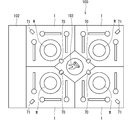
- FIG. 1 is a diagram illustrating an overall configuration of a substrate processing apparatus 100 according to the first embodiment.
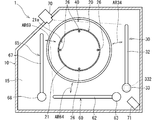
- FIG. 2 is a schematic plan view of the cleaning unit 1 according to the first embodiment.
- FIG. 3 is a schematic vertical sectional view of the cleaning unit 1 of the first embodiment.
- FIG. 4 is a diagram illustrating a positional relationship between the camera 70 and the nozzle 30 that is a movable unit.
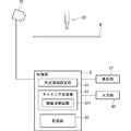
- FIG. 5 is a block diagram of the camera 70 and the control unit 9.
- FIG. 6 is a diagram illustrating an example of a flow of substrate processing in one cleaning processing unit 1 of the substrate processing apparatus 100.
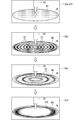
- FIG. 7 is a diagram showing captured images 82a, 82b, 82c, and 82d at each timing during the transition from the first processing to the second processing.
- FIG. 8 is a diagram illustrating a first detection pattern of the interference fringe ST.
- FIG. 9 is a diagram illustrating a second detection pattern of the interference fringe ST.
- FIG. 10 is a diagram illustrating a third detection pattern of the interference fringe ST.
- FIG. 11 is a diagram illustrating a flow of processing for determining the second processing start timing.
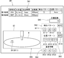
- FIG. 12 is a diagram showing a setting screen SW1 for setting conditions for detecting the interference fringe ST.
- FIG. 13 is a diagram illustrating a substrate processing apparatus 100A according to the second embodiment.
- FIG. 1 is a diagram illustrating an overall configuration of a substrate processing apparatus 100 according to the first embodiment.
- the substrate processing apparatus 100 is a single-wafer processing apparatus that processes substrates W (also referred to as target substrates) to be processed one by one.
- the substrate processing apparatus 100 performs a cleaning process on a substrate W, which is a silicon substrate having a circular thin plate shape, using a rinsing solution such as a chemical solution and pure water, and then performs a drying process.
- a chemical solution for example, SC1 (ammonia-hydrogen peroxide mixture), SC2 (hydrochloric hydrogen peroxide mixed water solution), DHF solution (dilute hydrofluoric acid) and the like are used.
- the chemical liquid and the rinsing liquid may be collectively referred to as “treatment liquid”.
- the substrate processing apparatus 100 supplies a coating solution such as a photoresist solution for a film formation process, a chemical solution for removing an unnecessary film, or a chemical solution for etching, instead of a cleaning process, and performs a wet process on the substrate. It may be configured to perform processing. That is, the substrate processing apparatus 100 may be, for example, an apparatus that performs liquid processing on the upper surface of the substrate W rotating in a horizontal posture. The liquid processing is processing using a processing liquid for the substrate W.
- the substrate processing apparatus 100 includes a plurality of cleaning units 1, an indexer 102, and a main transfer robot 103.
- the indexer 102 transports the substrate W to be processed received from outside the apparatus (substrate processing apparatus 100) into the apparatus (substrate processing apparatus 100), and transfers the processed substrate W, which has been subjected to the cleaning process, to the apparatus (substrate processing apparatus 100). 100) Take it out.
- the indexer 102 mounts a plurality of carriers (not shown) and includes a transfer robot (not shown).
- a FOUP Front Opening Unified Unified Pod
- SMIF Standard Mechanical InterFace
- OC Open Cassette
- the cleaning unit 1 performs liquid processing and drying processing on one substrate W.
- twelve cleaning processing units 1 are arranged. Specifically, four towers each including three cleaning units 1 stacked in the vertical direction are arranged so as to surround the main transfer robot 103.
- FIG. 1 schematically shows one of the cleaning units 1 stacked in three stages.
- the number of cleaning units 1 in the substrate processing apparatus 100 is not limited to 12, and may be changed as appropriate.
- the main transfer robot 103 is installed at the center of the four towers on which the cleaning units 1 are stacked.
- the main transfer robot 103 loads the substrate W to be processed, received from the indexer 102, into each cleaning processing unit 1.
- the main transport robot 103 unloads the processed substrate W from each cleaning processing unit 1 and delivers it to the indexer 102.
- ⁇ Cleaning unit 1> one of the twelve cleaning processing units 1 mounted on the substrate processing apparatus 100 will be described. However, the other cleaning processing units 1 are also different except that the arrangement relationship of the nozzles 30, 60, and 65 is different. It has the same configuration.
- FIG. 2 is a schematic plan view of the cleaning unit 1 according to the first embodiment.
- FIG. 3 is a schematic vertical sectional view of the cleaning unit 1 of the first embodiment.
- FIG. 2 shows a state where the substrate W is not held on the spin chuck 20, and
- FIG. 3 shows a state where the substrate W is held on the spin chuck 20.
- the cleaning unit 1 includes a spin chuck 20 that holds a substrate W in a horizontal position (a position in which the normal of the surface of the substrate W is along the vertical direction) in the chamber 10, and an upper surface of the substrate W held by the spin chuck 20.
- Nozzles also referred to as processing liquid supply units
- Nozzles 30, 60, and 65 for supplying a processing liquid to the substrate
- a processing cup 40 surrounding the periphery of the spin chuck 20 for imaging the space above the spin chuck 20.
- a partition plate 15 is provided around the processing cup 40 in the chamber 10 to vertically partition the inner space of the chamber 10.
- the chamber 10 includes a side wall 11 extending in the vertical direction and surrounding four sides, a ceiling wall 12 closing the upper side of the side wall 11, and a floor wall 13 closing the lower side of the side wall 11.
- the space surrounded by the side wall 11, the ceiling wall 12, and the floor wall 13 is a processing space for the substrate W.
- a part of the side wall 11 of the chamber 10 is provided with a loading / unloading port for the main transfer robot 103 to load / unload the substrate W into / from the chamber 10 and a shutter for opening / closing the loading / unloading port (both not shown). Have been.
- a fan filter unit (FFU) 14 for further purifying air in a clean room where the substrate processing apparatus 100 is installed and supplying the air to a processing space in the chamber 10 is attached to the ceiling wall 12 of the chamber 10.
- the FFU 14 includes a fan and a filter (for example, a HEPA filter) for taking in air in the clean room and sending the air into the chamber 10.
- the FFU 14 forms a downflow of clean air in the processing space in the chamber 10.
- a punching plate having a number of blowout holes may be provided directly below the ceiling wall 12.
- the spin chuck 20 includes a spin base 21, a spin motor 22, a cover member 23, and a rotating shaft 24.
- the spin base 21 has a disk shape, and is fixed in a horizontal posture to an upper end of a rotating shaft 24 extending along the vertical direction.
- the spin motor 22 is provided below the spin base 21 and rotates the rotation shaft 24.
- the spin motor 22 rotates the spin base 21 via a rotation shaft 24 in a horizontal plane.
- the cover member 23 has a cylindrical shape surrounding the spin motor 22 and the rotation shaft 24.
- the outer diameter of the disc-shaped spin base 21 is slightly larger than the diameter of the circular substrate W held by the spin chuck 20. Therefore, the spin base 21 has a holding surface 21a facing the entire lower surface of the substrate W to be held.
- a plurality (four in the present embodiment) of chuck pins 26 are provided upright on the periphery of the holding surface 21a of the spin base 21.
- the chuck pins 26 are arranged at equal intervals along the circumference corresponding to the outer shape of the outer peripheral circle of the circular substrate W.
- four chuck pins 26 are provided at 90 ° intervals.
- Each of the chuck pins 26 is driven in conjunction with each other by a link mechanism (not shown) accommodated in the spin base 21.
- the spin chuck 20 holds the substrate W by bringing each of the chuck pins 26 into contact with the outer peripheral edge of the substrate W, thereby holding the substrate W in a horizontal posture close to the holding surface 21 a above the spin base 21. Hold (see FIG. 3).
- the spin chuck 20 releases the grip of the substrate W by separating each of the chuck pins 26 from the outer peripheral end of the substrate W.
- Each chuck pin 26 is a substrate holding unit that holds the substrate W in a horizontal posture.
- the cover member 23 covering the spin motor 22 has its lower end fixed to the floor wall 13 of the chamber 10 and its upper end reaching just below the spin base 21.
- a flange-like member 25 that extends substantially horizontally outward from the cover member 23 and that bends downward and extends further is provided.
- the horizontal direction orthogonal to the rotation axis CX is referred to as “radial direction”.
- the direction toward the rotation axis CX in the radial direction is referred to as “radially inward”, and the direction away from the rotation axis CX in the radial direction is referred to as “radially outward”.
- the nozzle 30 is configured by attaching a discharge head 31 to the tip of a nozzle arm 32.
- the base end of the nozzle arm 32 is fixedly connected to a nozzle base 33.
- the nozzle base 33 is rotatable around a vertical axis by a motor 332 (nozzle moving unit; see FIG. 4) provided on the nozzle base 33.
- the nozzle 30 moves in the horizontal direction between a position above the spin chuck 20 and a standby position outside the processing cup 40 as indicated by an arrow AR34 in FIG. Is moved in an arc along the line. Due to the rotation of the nozzle base 33, the nozzle 30 swings above the holding surface 21a of the spin base 21. More specifically, it moves to a predetermined processing position TP1 extending in the horizontal direction above the spin base 21. Moving the nozzle 30 to the processing position TP1 is synonymous with moving the ejection head 31 at the tip of the nozzle 30 to the processing position TP1.
- the nozzle 30 is configured to be supplied with a plurality of types of processing liquids (including at least pure water), so that the discharging head 31 can discharge a plurality of types of processing liquids.
- a plurality of ejection heads 31 may be provided at the tip of the nozzle 30, and the same or different treatment liquids may be individually ejected from each of them.
- the nozzle 30 (specifically, the discharge head 31) stops at the processing position TP1, and discharges the processing liquid.
- the processing liquid discharged from the nozzle 30 lands on the upper surface of the substrate W held by the spin chuck 20.
- the cleaning unit 1 of this embodiment is provided with two nozzles 60 and 65 in addition to the nozzle 30 described above.
- the nozzles 60 and 65 of the present embodiment have the same or similar configuration as the nozzle 30 described above. That is, the nozzle 60 is configured by attaching a discharge head to the distal end of the nozzle arm 62, and the nozzle base 63 connected to the proximal end side of the nozzle arm 62 is provided above the spin chuck 20 as indicated by an arrow AR64. It moves in an arc between the processing position and the standby position outside the processing cup 40.
- the nozzle 65 is configured by attaching a discharge head to the tip of a nozzle arm 67, and a processing position above the spin chuck 20 as indicated by an arrow AR69 by a nozzle base 68 connected to the base end of the nozzle arm 67. And the standby position outside the processing cup 40 in an arc shape.
- the nozzles 60 and 65 are also configured to be supplied with a plurality of types of processing liquids including at least pure water.
- the nozzles 60 and 65 are also provided on the upper surface of the substrate W held by the spin chuck 20 at the processing position. Is discharged.
- At least one of the nozzles 60 and 65 is a two-fluid nozzle that mixes a cleaning liquid such as pure water and a pressurized gas to generate droplets, and jets a mixed fluid of the droplets and the gas to the substrate W. It may be.
- the number of nozzles provided in the cleaning processing unit 1 is not limited to three, but may be one or more.
- each of the nozzles 30, 60, 65 may be moved linearly by providing a linear drive unit.
- the nozzle 30 may be made of various types of water such as pure water (DIW) as a rinsing liquid, IPA (Isopropyl alcohol: isopropyl alcohol), a water repellent such as a silylating agent, DHF (Dilute HF: a mixture of hydrofluoric acid and pure water). It is connected to the supply source of the processing liquid, and can discharge various processing liquids separately from the discharge head 31 at the tip of the nozzle 30. Note that a plurality of ejection heads 31 may be provided at the tip of the nozzle 30, and each ejection head 31 may eject a different type of processing liquid. Further, the nozzles 60 and 65 may discharge a part of the above-described various processing liquids.
- DIW pure water
- IPA Isopropyl alcohol: isopropyl alcohol
- a water repellent such as a silylating agent
- DHF Dilute HF: a mixture of hydrofluoric acid and pure water
- a lower surface processing liquid nozzle 28 is provided along the vertical direction so as to pass through the inside of the rotating shaft 24.
- the upper end opening of the lower processing liquid nozzle 28 is formed at a position facing the center of the lower surface of the substrate W held by the spin chuck 20.
- the lower processing liquid nozzle 28 is also configured to supply a plurality of types of processing liquid. The processing liquid discharged from the lower processing liquid nozzle 28 lands on the lower surface of the substrate W held by the spin chuck 20.
- the processing cup 40 surrounding the spin chuck 20 includes an inner cup 41, a middle cup 42, and an outer cup 43 which can be raised and lowered independently of each other.
- the inner cup 41 has a shape that surrounds the periphery of the spin chuck 20 and is substantially rotationally symmetric with respect to a rotation axis CX passing through the center of the substrate W held by the spin chuck 20.
- the inner cup 41 has an annular bottom portion 44 in plan view, a cylindrical inner wall portion 45 rising upward from the inner peripheral edge of the bottom portion 44, a cylindrical outer wall portion 46 rising upward from the outer peripheral edge of the bottom portion 44, and an inner wall.
- the first guide portion 47 which rises from between the portion 45 and the outer wall portion 46 and extends obliquely upward at the center (in a direction approaching the rotation axis CX of the substrate W held by the spin chuck 20) while drawing a smooth arc at the upper end. And a cylindrical middle wall 48 rising upward from between the first guide portion 47 and the outer wall 46.
- the inner wall portion 45 is housed with an appropriate gap between the cover member 23 and the flange member 25 with the inner cup 41 raised most.
- the middle wall portion 48 is accommodated in a state where the inner cup 41 and the middle cup 42 are closest to each other, with an appropriate gap kept between a second guide portion 52 described later of the middle cup 42 and the processing liquid separation wall 53. You.
- the first guide portion 47 has an upper end portion 47b extending obliquely upward toward the center (in a direction approaching the rotation axis CX of the substrate W) while drawing a smooth arc. Further, between the inner wall portion 45 and the first guide portion 47, a disposal groove 49 for collecting and discarding the used processing liquid is formed. An annular inner collecting groove 50 for collecting and collecting used processing liquid is provided between the first guide portion 47 and the middle wall portion 48. Further, between the middle wall portion 48 and the outer wall portion 46, there is an annular outer collection groove 51 for collecting and collecting different types of processing liquids from the inner collection groove 50.
- An exhaust liquid mechanism (not shown) for discharging the treatment liquid collected in the waste groove 49 and forcibly exhausting the waste groove 49 is connected to the waste groove 49.
- four exhaust liquid mechanisms are provided at equal intervals along the circumferential direction of the waste groove 49.
- the inner collecting groove 50 and the outer collecting groove 51 have a collecting mechanism for collecting the processing liquid collected in the inner collecting groove 50 and the outer collecting groove 51 into a collecting tank provided outside the substrate processing apparatus 100. (Both not shown) are connected.
- the bottoms of the inner recovery groove 50 and the outer recovery groove 51 are inclined by a small angle with respect to the horizontal direction, and the recovery mechanism is connected to the lowest position.
- the processing liquid flowing into the inner recovery groove 50 and the outer recovery groove 51 is smoothly recovered.
- the middle cup 42 has a shape that surrounds the periphery of the spin chuck 20 and is substantially rotationally symmetric with respect to a rotation axis CX passing through the center of the substrate W held by the spin chuck 20.
- the middle cup 42 has a second guide portion 52 and a cylindrical processing liquid separation wall 53 connected to the second guide portion 52.
- the second guide part 52 draws a smooth arc outside the first guide part 47 of the inner cup 41 from the upper end of the lower end part 52a which is coaxially cylindrical with the lower end part of the first guide part 47, and the lower end part 52a. It has an upper end portion 52b extending obliquely upward toward the center (in a direction approaching the rotation axis CX of the substrate W), and a folded portion 52c formed by folding the distal end portion of the upper end portion 52b downward.
- the lower end portion 52a is accommodated in the inner recovery groove 50 with an appropriate gap between the first guide portion 47 and the middle wall portion 48 in a state where the inner cup 41 and the middle cup 42 are closest to each other.
- the upper end portion 52b is provided so as to vertically overlap the upper end portion 47b of the first guide portion 47 of the inner cup 41, and when the inner cup 41 and the middle cup 42 are closest to each other, the first guide portion 47 is provided. Is kept close to the upper end portion 47b at a very small interval.
- the folded portion 52c horizontally overlaps the tip of the upper end portion 47b of the first guide portion 47 when the inner cup 41 and the middle cup 42 are closest to each other.
- the upper end portion 52b of the second guide portion 52 is formed so as to be thicker downward.
- the processing liquid separation wall 53 has a cylindrical shape provided to extend downward from the outer peripheral edge of the lower end of the upper end 52b.
- the processing liquid separation wall 53 is accommodated in the outer recovery groove 51 with an appropriate gap between the middle wall portion 48 and the outer cup 43 with the inner cup 41 and the middle cup 42 being closest to each other.
- the outer cup 43 has a shape that is substantially rotationally symmetric with respect to a rotation axis CX passing through the center of the substrate W held by the spin chuck 20.
- the outer cup 43 surrounds the spin chuck 20 outside the second guide portion 52 of the middle cup 42.
- the outer cup 43 has a function as a third guide.
- the outer cup 43 has a lower end portion 43a coaxial with the lower end portion 52a of the second guide portion 52, and a central side (in a direction approaching the rotation axis CX of the substrate W) while drawing a smooth arc from the upper end of the lower end portion 43a. It has an upper end portion 43b extending obliquely upward and a folded portion 43c formed by folding a tip end of the upper end portion 43b downward.
- the lower end portion 43a When the inner cup 41 and the outer cup 43 are closest to each other, the lower end portion 43a is formed with an outer collecting groove while maintaining an appropriate gap between the processing liquid separation wall 53 of the middle cup 42 and the outer wall portion 46 of the inner cup 41. 51.
- the upper end portion 43b is provided so as to overlap the second guide portion 52 of the middle cup 42 in the up-down direction, and when the middle cup 42 and the outer cup 43 are closest to each other, the upper end portion 43b is located on the upper end portion 52b of the second guide portion 52. Keep close together with very small intervals.
- the folded portion 43c overlaps the folded portion 52c of the second guide portion 52 in the horizontal direction.
- the inner cup 41, the middle cup 42, and the outer cup 43 can be raised and lowered independently of each other. That is, each of the inner cup 41, the middle cup 42, and the outer cup 43 is individually provided with an elevating mechanism (not shown), whereby the inner cup 41, the middle cup 42, and the outer cup 43 are independently lifted and lowered. Is done.
- an elevating mechanism various known mechanisms such as a ball screw mechanism or an air cylinder can be adopted.
- the partition plate 15 is provided so as to vertically partition the inner space of the chamber 10 around the processing cup 40.
- the partition plate 15 may be a single plate member surrounding the processing cup 40, or may be a combination of a plurality of plate members. Further, the partition plate 15 may be formed with a through hole and / or a notch penetrating in the thickness direction, and in the present embodiment, supports the nozzle bases 33, 63, 68 of the nozzles 30, 60, 65. A through-hole for passing a support shaft through the support shaft is formed.
- the outer peripheral end of the partition plate 15 is connected to the side wall 11 of the chamber 10.
- the edge of the partition plate 15 surrounding the processing cup 40 is formed in a circular shape having a diameter larger than the outer diameter of the outer cup 43. Therefore, the partition plate 15 does not prevent the outer cup 43 from moving up and down.
- An exhaust duct 18 is provided in a part of the side wall 11 of the chamber 10 and near the floor wall 13.
- the exhaust duct 18 is connected to an exhaust mechanism (not shown).
- the air passing between the processing cup 40 and the partition plate 15 is discharged from the exhaust duct 18 to the outside of the apparatus.
- FIG. 4 is a diagram showing a positional relationship between the camera 70 and the nozzle 30 as a movable part.
- the camera 70 is provided vertically above the substrate W in the vertical direction.
- the camera 70 includes, for example, a CCD that is one of solid-state imaging devices, an electronic shutter, and an optical system such as a lens.
- the imaging direction of the camera 70 (that is, the optical axis direction of the imaging optical system) is set obliquely downward toward the rotation center of the upper surface of the substrate W (or in the vicinity thereof) in order to image the upper surface of the substrate W.
- the camera 70 covers the entire top surface of the substrate W held by the spin chuck 20 in its field of view. For example, in the horizontal direction, a range surrounded by a broken line in FIG. In other words, the two broken lines in FIG. 2 indicate the outer edge of the field of view of the camera 70.
- the camera 70 is installed so that its imaging visual field includes at least the tip of the nozzle 30 at the processing position TP1, that is, at a position including the vicinity of the ejection head 31.
- the camera 70 is installed at a position where the nozzle 30 at the processing position TP1 is imaged from the upper front. Therefore, the camera 70 can capture an image of the imaging region including the tip of the nozzle 30 at the processing position TP1.
- the camera 70 captures an image of an imaging region including each tip when the nozzles 60 and 65 are at the processing position when performing processing on the substrate W held on the spin chuck 20.
- the nozzles 30 and 60 move in the horizontal direction within the imaging field of view of the camera 70, so that the tips of the nozzles 30 and 60 at each processing position Can be properly imaged, but since the nozzle 65 moves in the depth direction within the field of view of the camera 70, the movement near the processing position may not be properly imaged.
- a camera for imaging the nozzle 65 may be provided separately from the camera 70.
- the nozzle 30 is driven by the nozzle base 33 to move the processing position TP1 (the position indicated by the broken line in FIG. 4) above the substrate W held by the spin chuck 20 and the standby position outside the processing cup 40 (FIG. 4).
- the processing position TP1 is a position where the nozzle 30 performs a cleaning process by discharging a processing liquid onto the upper surface of the substrate W held by the spin chuck 20.
- the processing position TP1 is a position near the center (the rotation axis CX) of the substrate W held by the spin chuck 20.
- the standby position is a position where the nozzle 30 stops discharging the processing liquid and waits when the nozzle 30 does not perform the cleaning process.
- the standby position is a position deviated from above the spin base 21 and a position outside the processing cup 40 in a horizontal plane.
- a standby pod that accommodates the ejection head 31 of the nozzle 30 may be provided at the standby position.
- the processing position TP1 may be an arbitrary position such as a position near the edge of the substrate W. Further, the processing position TP1 is at a position deviating from the substrate W (that is, does not vertically overlap with the substrate W). State). In the latter case, the processing liquid discharged from the nozzle 30 may be scattered from outside the substrate W onto the upper surface of the substrate W. It is not essential that the processing liquid be ejected from the nozzle 30 while the nozzle 30 is stopped at the processing position TP1. For example, while discharging the processing liquid from the nozzle 30, the nozzle 30 may be moved within a predetermined processing section extending in the horizontal direction above the substrate W with the processing position TP1 as one end.
- an illumination unit 71 is provided in the chamber 10 at a position above the partition plate 15.
- the illumination unit 71 includes, for example, an LED lamp as a light source.
- the illumination unit 71 supplies illumination light required for the camera 70 to image the inside of the chamber 10 to the processing space.
- the control unit 9 may control the illumination unit 71 so that the illumination unit 71 irradiates the nozzles 30, 60, 65 with light when the camera 70 performs imaging.
- the illumination unit 71 emits visible light as illumination light.
- the illumination light is not limited to visible light.
- an infrared ray having a wavelength of about 0.7 micrometer ( ⁇ m) to 1 millimeter (mm), more preferably a near infrared ray having a wavelength of about 0.7 ⁇ m to 2.5 ⁇ m can be employed.
- the camera 70 an infrared camera provided with an infrared sensor that detects infrared rays (more preferably, near infrared rays) can be adopted. By detecting infrared rays, interference fringes can be suitably detected.
- FIG. 5 is a block diagram of the camera 70 and the control unit 9.
- the configuration of the control unit 9 provided in the substrate processing apparatus 100 as hardware is the same as that of a general computer. That is, the control unit 9 includes a CPU that performs various arithmetic processes, a ROM that is a read-only memory that stores a basic program, a RAM that is a readable and writable memory that stores various information, and control software (program) and data. It has a magnetic disk and the like for storing.
- the CPU of the control unit 9 executes a predetermined processing program, the operation of each element of the substrate processing apparatus 100 is controlled by the control unit 9 and the processing in the substrate processing apparatus 100 proceeds.
- the determination area setting unit 91 and the timing determination unit 92 shown in FIG. 5 are functions realized by the CPU of the control unit 9 operating according to the control software.
- the determination area setting unit 91 sets the determination area DR on the captured image 82 acquired by the camera 70.
- the size, position, number, and the like of the determination region DR may be determined in advance, or may be set based on an operator's designation.
- the timing determination unit 92 After the previous processing (first processing) of processing the substrate W with the liquid, the timing determination unit 92 starts the subsequent processing (second processing) by detecting the interference fringes ST appearing on the upper surface of the substrate W. (Hereinafter, also referred to as “second processing start timing”).
- the first process is a process of supplying a first processing liquid to the upper surface of the rotating substrate W.
- the timing determination unit 92 detects each interference fringe ST in the determination area DR set in the captured image 82. Further, as described later, the detection of the interference fringe ST in the determination region DR is performed by the extreme point detecting unit 921 included in the timing determining unit 92 detecting the extreme point of the luminance value.
- the control unit 9 includes a storage unit 96 including the above RAM or magnetic disk.
- the storage unit 96 stores image data obtained by the camera 70, input values of the operator, and the like.
- the display unit 97 and the input unit 98 are connected to the control unit 9.
- the display unit 97 displays various information according to the image signal from the control unit 9.
- the input unit 98 includes an input device such as a keyboard and a mouse connected to the control unit 9 and receives an input operation performed by the operator on the control unit 9.
- FIG. 6 is a diagram illustrating an example of a flow of substrate processing in one cleaning processing unit 1 of the substrate processing apparatus 100. Each step described below is performed under the control of the control unit 9 unless otherwise specified.
- the main transport robot 103 loads the substrate W to be processed, received from the indexer 102, into the chamber 10 of any one of the cleaning processing units 1 (step S10).
- the substrate carried into the chamber 10 is placed on each of the chuck pins 26 of the spin base 21.
- the chuck pins 26 are closed, the substrate W is held in a horizontal posture.
- the rotation of the substrate W is started by the spin motor 22.
- a hydrofluoric acid process for supplying hydrofluoric acid from the nozzle 30 to the upper surface of the substrate W is performed (step S11).
- the hydrofluoric acid supplied to the upper surface of the substrate W spreads to the outer edge of the substrate W by the rotation of the substrate W, and the hydrofluoric acid process proceeds on the entire substrate W.
- the period during which hydrofluoric acid is supplied to the substrate W is, for example, 30 seconds.
- the rotation speed of the substrate W during this period is, for example, 800 rpm (revolution per minute: rotation number / minute).
- a rinsing liquid process for supplying a rinsing liquid (DIW) from the nozzle 30 to the upper surface of the substrate W is performed (Step S12).
- DIW a rinsing liquid
- the rinsing liquid is continuously supplied from the nozzle 30 to the upper surface of the rotating substrate W.
- the rinsing liquid supplied to the upper surface of the substrate W spreads to the outer edge of the substrate W by the rotation of the substrate W. Then, the hydrofluoric acid remaining on the upper surface of the substrate W is shaken radially outward from the outer edge of the substrate W.
- the hydrofluoric acid and the rinsing liquid shaken off from the substrate W are received by the processing cup 40 and are appropriately discarded.
- the period during which the rinsing liquid is supplied to the substrate W is, for example, 30 seconds.
- the rotation speed of the substrate W during this period is, for example, 1200 rpm.
- Step S13 After the discharge of the rinsing liquid from the nozzle 30 is stopped, an IPA process of supplying IPA from the nozzle 30 to the upper surface of the substrate W is performed (Step S13).
- IPA is continuously supplied to the upper surface of the substrate W rotating from the nozzle 30.
- the IPA supplied to the upper surface is spread to the outer edge of the substrate W by the rotation of the substrate W, and the rinsing liquid (DIW) is replaced with the IPA on the entire upper surface (the upper surface of the substrate W).
- DIW rinsing liquid
- a heat treatment may be performed on the substrate W by a heating mechanism (not shown) for the purpose of prompting the replacement of DIW with IPA.
- the period during which the IPA is supplied is, for example, 30 seconds.
- the rotation speed of the substrate W during this period is, for example, 300 rpm.
- a water-repellent treatment for supplying a water-repellent from the nozzle 30 to the upper surface of the substrate W is performed (step S14).
- the water repellent supplied to the upper surface of the substrate W spreads to the outer edge of the substrate W by the rotation of the substrate W, and IPA is replaced with the water repellent on the entire upper surface (the upper surface of the substrate W).
- a water-repellent treatment for modifying the upper surface (the upper surface of the substrate W) to be water-repellent proceeds.
- the period during which the water repellent is supplied is, for example, 30 seconds.
- the rotation speed of the substrate W during this period is, for example, 500 rpm.
- step S15 After the discharge of the water repellent from the nozzle 30 is stopped, the same IPA processing as in step S13 is performed (step S15). By the IPA processing, the water repellent remaining on the upper surface of the substrate W is replaced with the IPA processing liquid.
- a spin dry process is executed (step S16).
- the spin motor 22 rotates the substrate W at a higher rotation speed than in the respective liquid processes in steps S11 to S15.
- the rotation speed at this time is, for example, 1500 rpm.
- Various liquids adhered to the substrate W by the spin dry process are scattered radially outward from the outer peripheral portion (the outer peripheral portion of the substrate W), received by the inner wall of the processing cup 40, and appropriately drained.
- the rotation speed of the substrate W is set higher than that in the IPA process, and IPA as a processing liquid remaining on the upper surface of the substrate W is removed.
- Step S17 When the spin dry process is completed, the holding of the substrate W by the chuck pins 26 is released, and the main transport robot 103 unloads the substrate W from the chamber 10 (Step S17).
- the processing by the cleaning processing unit 1 includes a liquid processing step of performing liquid processing on the substrate W (steps S11 to S15) and a drying processing step of performing a drying processing of drying the substrate W (step S16). including.
- the timing determination unit 92 determines the timing at which the next processing is started. . For example, after the discharge of IPA from the nozzle 30 in the IPA process (first process) in step S13 is stopped, the timing determination unit 92 determines that the nozzle 30 in the next process, ie, the water-repellent process (second process), has stopped. The second processing start timing at which the discharge of the water repellent is started is determined. As described above, the timing determination unit 92 determines the timing at which the next processing is executed in accordance with the detection of the interference fringe ST. Here, the interference fringes ST appearing on the upper surface of the substrate W will be described.
- FIG. 7 is a diagram showing captured images 82a, 82b, 82c, and 82d at each timing during the transition from the first process to the second process.
- the captured image 82a shows a state in which the processing liquid is supplied to the upper surface of the substrate W from the nozzle 30 in the first processing.
- the processing liquid moves radially outward on the upper surface of the substrate W, and drops or radially outwards from the outer edge of the substrate W. Shake off.
- the liquid film W1 which is a film of the processing liquid is formed on the upper surface of the substrate W. Is formed.
- the photographed image 82b shows the state of the upper surface of the substrate W when a predetermined time has elapsed since the supply of the processing liquid from the nozzle 30 was stopped.
- the processing liquid on the surface of the substrate W is scattered outward in the radial direction, so that the liquid film W1 (the remaining liquid on the upper surface of the substrate W) is formed.
- a film of one processing solution gradually becomes thinner. In the process of reducing the film thickness, light reflected on the upper surface of the substrate W and light reflected on the surface of the liquid film W1 interfere with each other.
- a portion where the phases of these two lights coincide with each other appears as a bright band region, and a portion where the phases of these two lights are opposite appears as a dark band region.
- bright and dark stripes alternately appear in the radial direction (the radial direction of the substrate W), so that bright and dark stripes are observed.
- one dark band area is defined as an interference fringe ST.
- a bright band area may be regarded as an interference fringe.
- each interference fringe ST appears in an annular band shape (loop shape) on the substrate W and moves while spreading radially outward. Note that the interference fringes ST do not always appear in a perfect annular shape.
- the captured image 82c shows the state of the upper surface of the substrate W when the time has further elapsed from the state shown in the captured image 82b.
- the interval between adjacent interference fringes ST in the radial direction gradually increases.
- the substrate W is in a state of being covered with the liquid film W1 having a thickness close to the minimum.
- the second processing start timing is appropriately determined by setting at least one of the interference fringes ST constituting the stripe pattern as a detection target. it can.
- the photographed image 82d shows a state of the upper surface of the substrate W when a further time has elapsed from the state shown in the photographed image 82c.
- the last interference fringe STL appears on the substrate W.
- the area inside the interference fringe STL there is a possibility that a dry area having no liquid component is partially generated.
- the second processing performed after the first processing is liquid processing using the second processing liquid.
- the second processing liquid is a processing liquid different from the first processing liquid in the first processing.
- the second processing liquid is supplied to the upper surface of the substrate W.
- the second processing liquid is supplied in a state where the liquid film W1 of the first processing liquid is thick as in the captured images 82a and 82b, it may take time to replace the first processing liquid with the second processing liquid. There is.
- the second processing liquid is supplied in a state where the dry area is partially generated as in the photographed image 82d, the time of exposure to the second processing liquid differs depending on the position of the substrate W. 2 There is a possibility that the processing will vary.
- the second process is a drying process such as a spin dry process
- the first processing liquid may be locally present in a small amount. In such a case, there is a possibility that it takes a long time to shake off even when shifting to high-speed rotation. Therefore, it may be preferable to start high-speed rotation before the state of the captured image 82d (that is, the state in which the last interference fringe STL has appeared).
- the liquid film W1 of the first processing liquid shifts to high-speed rotation as in the captured images 82a and 82b, the movement of the first processing liquid in the radially outward direction is biased.
- the timing determination unit 92 By appropriately setting the interference fringes ST to be detected by the timing determination unit 92 in advance in accordance with the contents of each of the first processing and the second processing, the timing determination unit 92 appropriately sets the second processing start timing. Can decide. Next, a detection pattern of the interference fringe ST will be described.
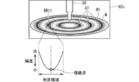
- FIG. 8 is a diagram illustrating a first detection pattern of the interference fringe ST.
- the first detection pattern is a mode in which the determination area setting unit 91 sets one determination area DR11 on the captured image 82.
- the determination region DR11 is set on the upper surface of the substrate W on which the liquid film W1 is formed on the captured image 82.
- the vertical position of the determination region DR11 matches the center of the substrate W in the captured image 82.
- the interference fringes ST move radially outward, the interference fringes ST pass in the horizontal direction of the captured image 82 in the determination region DR11. That is, the interference fringes ST move radially outward in the determination region DR11.
- the determination area DR11 is set to such a size that it can overlap with only one interference fringe ST to be detected.
- the width of the determination region DR11 in the radial direction (radial direction of the substrate W) is larger than the distance in the radial direction (radial direction of the substrate W) between adjacent interference fringes ST. small.
- the interval between the interference fringes ST changes according to the thickness of the liquid film W1.
- the interval between the interference fringes ST is relatively small when the liquid film W1 is thick as shown in the captured image 82b of FIG. 7, and between the interference fringes ST when the liquid film W1 is thin as shown in the captured image 82c.
- the spacing is relatively large.
- the size of the determination region DR11 may be set according to the width between the interference fringes ST when the interference fringes ST to be detected appear.
- an area where the light intensity is relatively weak with respect to the surroundings is defined as the interference fringe ST. Therefore, when passing through the determination region DR11, the luminance indicating the light intensity in the horizontal direction in the determination region DR11 gradually decreases from the radially inner side to the outer side and then increases again as shown in FIG. Become. Then, the point (position) where the luminance becomes the minimum value corresponds to the point (position) substantially at the center of the interference fringe ST. For this reason, the extremum point detection unit 921 detects an extremum point having a minimum value of the luminance (minimum value of the light intensity in the radial direction of the substrate W) in the determination region DR11, thereby detecting the interference fringe ST in the determination region DR11. Passage can be detected.
- the extremum point detection unit 921 detects an extremum point at which the light intensity (luminance) has a maximum value in the radial direction (radial direction of the substrate W), and thereby the interference fringe which is a bright portion in the determination region DR11. May be detected.
- the timing determination unit 92 determines the first detection time at which the n-th (n is a natural number) interference fringe ST (first extreme value point) is detected, and the interference fringes generated after the (n + 1) -th time
- a detection time difference which is a difference from a second detection time at which ST (second extreme point) is detected, is calculated.
- the second detection time may be a time during which the (n + 1) th interference fringe ST is detected, or a time during which the (n + 2) th interference fringe ST occurring thereafter is detected. Since the interval between the interference fringes ST changes according to the thickness of the liquid film W1, the detection time difference is considered to correspond to the thickness of the liquid film W1.
- the timing determination unit 92 may determine that the interference fringe ST to be detected has been detected and determine the second processing start timing. .
- the timing determination unit 92 performs the second processing in accordance with the detection time difference as the time from the detection of one extreme point to the detection of the next extreme point in the determination region DR11. The start timing may be determined.
- the timing determination unit 92 responds to the movement of the extreme point where the light intensity in the radial direction of the substrate W becomes the maximum value or the minimum value in the determination region DR11 toward the outside in the radial direction.
- the second processing start timing as the timing at which the second processing is performed on the substrate W can be determined.
- the interference fringe ST to be detected may be determined based on each detection time of three or more interference fringes ST in the determination region DR11. For example, the first detection time difference between the first interference fringe ST (first extreme point) and the second interference fringe ST (second extreme point) and the second interference fringe ST (second extreme value) ) And the second detection time difference between the third interference fringe ST (third extreme point).
- the first detection time difference is determined by the first detection time at which the first interference fringe ST (first extreme point) is detected and the second interference fringe ST (second extreme point) are detected. This is a difference from the detected second detection time.
- the second detection time difference is a second detection time at which the second interference fringe ST (second extreme point) is detected and a third detection time at which the third interference fringe ST (third extreme point) is detected. It is the difference from time. Then, the second processing start timing may be determined based on a comparison between the first detection time difference and the second detection time difference. More specifically, when the difference between the first detection time difference and the second detection time difference becomes a predetermined value, it is determined that the interference fringe ST to be detected is detected, and the second processing is performed using that time as a guide. The start timing may be determined.
- the timing determination unit 92 determines that the second interference fringe ST (the second extreme value point) has been detected after the first interference fringe ST (the first extreme value point) is detected in the determination region DR11. ) Is detected as a first detection time difference as a first time, and a third interference fringe ST (third extreme value point) after the second interference fringe ST (second extreme value point) is detected.
- the second processing start timing may be determined based on the second detection time difference as the second time until () is detected.
- the first to third interference fringes ST may correspond to three extreme points counted from the last interference fringe STL corresponding to the last detectable final extreme point. .
- the timing determining unit 92 can appropriately determine whether the detection time difference corresponds to the target film thickness.
- the interference fringe ST generated when the liquid film W1 is thin may not be clearly detected due to noise such as fluctuation of the liquid surface. is there. Therefore, it is desirable that the interference fringes ST that can be detected as clearly as possible be detected. Further, a time obtained by adding a predetermined delay time to the time when the clear interference fringe ST is detected may be set as the second processing start timing. Thereby, the interference fringe ST to be detected can be detected with high accuracy, and the second processing can be started after the liquid film W1 has a suitable thickness.
- FIG. 9 is a diagram illustrating a second detection pattern of the interference fringe ST.
- the determination area setting unit 91 sets a plurality of determination areas DR21, DR22, DR23.
- the determination region DR21 as the first determination region
- the determination region DR22 as a second determination region radially outward from the determination region DR21
- the determination region DR22 radially outward from the determination region DR22.
- a determination area DR23 as a third determination area is set.
- three determination regions DR21, DR22, and DR23 are set in order from radially inward to radially outward. Note that the number of determination regions DR is not limited to three, and may be two or four or more.
- Each determination area DR21, DR22, DR23 is arranged at intervals in the horizontal direction of the captured image 82.
- the vertical positions of the determination regions DR21, DR22, DR23 coincide with the center of the substrate W in the captured image 82.
- the interference fringe ST moves radially outward to pass through the respective determination regions in the order of the determination region DR21, the determination region DR22, and the determination region DR23.
- Each determination region DR21, DR22, DR23 is set to a size that does not include a plurality of interference fringes ST at the same time as in the determination region DR11 of FIG.
- the horizontal width of each determination region DR is smaller than the radial interval between adjacent interference fringes ST.
- the intervals at which the determination areas DR21, DR22, DR23 are arranged may be set in accordance with the intervals of the plurality of interference fringes ST to be detected. Specifically, it may be set according to the number of interference fringes ST to be detected on the upper surface of the substrate W and the interval between the interference fringes ST.
- the detection target is three interference fringes ST (interference fringes ST1, ST2, ST3) appearing at the illustrated intervals
- three interference fringes ST are matched to the intervals of the three interference fringes ST.
- Determination regions DR21, DR22, DR23 are arranged.
- the distance between the interference fringe ST1 and the interference fringe ST2 radially outward from the interference fringe ST1 is defined as a first distance
- the distance between the interference fringe ST2 and the interference fringe ST2 is determined. It is conceivable that the distance to the interference fringe ST3 that is distant outward in the radial direction is the second distance.
- the extreme value detecting unit 921 detects the extreme value points having the minimum values in all of the determination regions DR21, DR22, and DR23
- the timing determining unit 92 determines that each interference fringe ST to be detected is detected.
- the extreme point detection unit 921 detects the extreme point as the first extreme value in the determination region DR21 as the first determination region.
- the timing determination unit 92 may determine that the interference fringes ST1 and ST2 to be detected have been detected. .
- the timing determination unit 92 detects the first extreme point in the determination area DR21 as the first determination area, and detects the second extreme point in the determination area DR22 as the second determination area. Based on this, the second processing start timing can be determined. In other words, for example, the timing determination unit 92 can determine the second processing start timing based on the first distance between the first extreme point and the second extreme point in the radial direction of the substrate W.
- the positions of the determination areas DR21, DR22, DR23 may be arbitrarily set by the operator.
- a captured image 82 in which each of the interference fringes ST to be detected has appeared is acquired in advance, and a frame indicating the determination areas DR21, DR22, and DR23 is displayed on the captured image 82 by the operator. It is good to move to the position.
- each determination region DR21, DR22, DR23 can be set at each position where each interference fringe ST to be detected can be simultaneously detected.
- the three interference fringes ST counted from the last interference fringe STL may be the three interference fringes ST1, ST2, and ST3 to be detected. That is, the last interference fringe STL may be the innermost interference fringe ST1 to be detected, and the two detection fringes ST generated immediately before the last interference fringe STL may be the interference fringes ST2 and ST3 to be detected.
- the timing at which the second processing is performed can be determined before the liquid film W1 becomes thin before the interference fringe ST becomes undetectable.
- the last interference fringe STL corresponds to the last extreme point that can be detected last.
- the timing determination unit 92 directs the light intensity in the radial direction of the substrate W to the maximum value or the minimum value in the determination regions DR21, DR22, and DR23, for example, radially outward. According to the movement, the second processing start timing as the timing of performing the second processing on the substrate W can be determined.
- FIG. 10 is a diagram illustrating a third detection pattern of the interference fringe ST.
- the determination area setting unit 91 sets one determination area RD31 on the captured image 82.
- the determination region RD31 has a shape extending in the radial direction (radial direction of the substrate W) (here, a rectangular shape extending in the horizontal direction in the captured image 82).
- the determination area RD31 is set to a size that can overlap with the plurality of interference fringes ST to be detected at the same time.
- the extremum point detection unit 921 detects an extremum point having an extremum minimum value in the determination region DR31.
- the timing determination unit 92 detects the interference fringe ST to be detected by specifying the extreme value point having the minimum value in the determination region DR31. Specifically, the timing determination unit 92 detects the interference fringe ST to be detected based on the distance between extreme points calculated in the determination region DR31.
- the distance between extreme points refers to a distance between points (positions) where the luminance becomes a minimum value in the determination region DR31.
- the distance between extreme points includes, for example, a distance (first distance) between the first extreme point and a second extreme point radially outward from the first extreme point.
- the distance between the extreme points includes, for example, a distance between the second extreme point and a third extreme point radially outward from the second extreme point (also referred to as a second distance). Is also good.
- the detection target is three interference fringes ST1, ST2, and ST3.
- the distances L1 and L2 corresponding to the intervals between these three interference fringes ST1, ST2 and ST3 are set in advance, and the timing determination unit 92 determines the distance between the extreme points detected in the determination area DR31. May correspond to L1 and L2.
- the interference fringes ST1, ST2, and ST3 exist in the determination region DR31, the interference fringes ST1, ST2, and ST3 to be detected are detected by determining that the distance between the extreme points corresponds to L1 and L2. .
- the timing determination unit 92 may detect the interference fringe ST to be detected based on the number of extreme points detected in the determination region DR31.
- the detection target is three interference fringes ST1, ST2, and ST3. For this reason, when three extreme points are detected in the determination region DR31, the timing determination unit 92 may determine that the interference fringes ST1, ST2, and ST3 to be detected have been detected.
- the second processing start timing may be determined based on the comparison between the extreme point distances L1 and L2. For example, when the difference between the extreme point distances L1 and L2 becomes a predetermined value, it may be determined that the interference fringes ST1, ST2 and ST3 to be detected have been detected. In other words, for example, when the distance L1 between the extreme points as the first distance becomes the predetermined distance and the distance L2 between the extreme points as the second distance becomes the predetermined distance, for example, It may be determined that the interference fringes ST1, ST2, ST3 to be detected have been detected. At this time, the timing determination unit 92 can determine the second processing start timing based on the first distance and the second distance.
- the timing determination unit 92 may determine that the interference fringes ST1 and ST2 to be detected have been detected when the distance L1 between extreme points as the first distance has reached a predetermined distance. In this case, the timing determination section 92 can determine the second processing start timing based on the distance L1 between extreme points as the first distance. Further, for example, the timing determining unit 92 may determine that the interference fringes ST2 and ST3 to be detected have been detected when the distance L2 between extreme points as the second distance has reached a predetermined distance. At this time, the timing determination unit 92 can determine the second processing start timing based on the distance L2 between extreme points as the second distance.
- the timing determination unit 92 performs the second process on the substrate W, for example, according to the extreme point where the light intensity in the radial direction of the substrate W becomes the maximum value or the minimum value in the determination region DR31.
- the second processing start timing as the timing can be determined. From another viewpoint, for example, the timing determination unit 92 determines that the extreme point at which the light intensity in the radial direction of the substrate W becomes the maximum value or the minimum value in the determination region DR31 moves outward in the radial direction. Accordingly, the second processing start timing as the timing of performing the second processing on the substrate W can be determined.
- FIG. 11 is a diagram showing a flow of processing for determining the second processing start timing.
- the IPA process (FIG. 6: step S13) is a first process
- the water repellent process (FIG. 6: step S14) is a second process
- the second process start timing discharge of the water repellent agent Is shown.
- IPA is supplied from the nozzle 30 to the upper surface of the substrate W (step S21).
- the camera 70 performs continuous shooting (step S22).
- the continuous imaging means that the camera continuously captures an image of the imaging region at a constant interval, and it is preferable to perform the continuous imaging at an interval of, for example, 33 milliseconds.
- the determination area setting unit 91 sets a determination area DR for the acquired captured image 82 (Step S23).
- the determination area DR set in step S23 differs depending on the detection pattern of the interference fringe ST to be detected. For example, in the case of the first detection pattern described with reference to FIG. 8, one determination region DR11 is set for the captured image 82. Further, for example, in the case of the second detection pattern described with reference to FIG. 9, in the step of setting the determination area DR for the captured image 82, the determination as the second determination area with respect to the determination area DR21 as the first determination area A step of changing the relative position of the region DR22 in the radial direction of the substrate W may be included.
- continuous imaging may be started while IPA is being ejected.
- continuous imaging may be performed from the time when the substrate W is carried into the chamber 10 to the time when it is carried out.
- Step S24 the supply of the IPA from the nozzle 30 to the substrate W is stopped.
- the IPA process (FIG. 6: step S13) is completed.
- the IPA on the substrate W is swung radially outward by the centrifugal force.
- the liquid film W1 becomes thinner gradually, and interference fringes ST begin to appear.
- the extreme point detecting unit 921 detects an extreme point at which the luminance has the minimum value in the radial direction in the determination region DR (Step S25). As a result, the interference fringe ST overlapping the determination region DR is detected as an extreme point having a minimum value.
- the timing determination unit 92 determines whether or not the interference fringe ST to be detected is detected (Step S26). The specific content of this determination differs depending on the detection pattern of the interference fringe ST. When it is determined that the interference fringe ST to be detected has not been detected (NO in step S26), the process returns to step S25, and the detection of the minimum value is continuously performed.
- the timing determination unit 92 determines the detection target when the detection time difference between the interference fringes ST detected in the determination area DR11 corresponds to a preset optimal detection time difference. It is determined that the interference fringe ST has been detected.
- the timing determination unit 92 detects the interference fringes ST1, ST2, ST3 to be detected. Is detected.
- the timing determination unit 92 detects the interference fringes ST1, ST2, ST3 to be detected. Is detected.
- the timing determination unit 92 determines in the determination area DR31 the distance between extreme points between the points (positions) at which the minimum value is detected is the distance L1, When corresponding to L2, it is determined that the interference fringes ST1, ST2, ST3 to be detected have been detected.
- the timing determination unit 92 determines the second processing start timing (step S27).
- the timing determination unit 92 determines the second processing start timing according to the detection completion time when the interference fringe ST to be detected is detected (the time when the minimum value corresponding to the interference fringe ST to be detected is detected). .
- the timing determination unit 92 sets a time obtained by adding a predetermined delay time from the detection completion time as the second processing start timing.
- step S28 the discharge of the water repellent from the nozzle 30 onto the upper surface of the substrate W is started at the second processing start timing (step S28).
- the water-repellent treatment (FIG. 6: step S14) is started.
- step S28 the control unit 9 causes the nozzle 30 to discharge the water-repellent agent as the next process according to the timing determined by the timing determination unit 92. That is, the control unit 9 executes the water repellency treatment as the next process according to the second process start timing.
- the control unit 9, the nozzle 30, and the mechanism for supplying the water repellent to the nozzle 30 can be an example of the second processing execution unit.
- the second processing execution unit is a part that performs the second processing on the substrate W to be processed, and can perform the second processing on the substrate W according to the timing determined by the timing determination unit 92.
- step S27 the length of the delay time added from the detection completion time to determine the second processing start timing may be determined in advance by experimental substrate processing. Specifically, after the interference fringe ST to be detected is detected, the water-repellent treatment is started at a different delay time, and the resulting hydrophobic state of the substrate W is evaluated. An optimum delay time may be determined based on this evaluation result.
- step S27 it is not essential that the second processing start timing be a time obtained by adding a predetermined delay time from the detection completion time.
- the second processing start timing may be the detection completion time. In this case, when it is determined in step S26 that the interference fringe ST to be detected is detected, the discharge of the water repellent is started immediately.
- the process is a process for determining the start timing of the second process.
- the combination of the first process and the second process is but, the present invention is not limited to this.
- the determination of the second process start timing is performed. Processing can be applied.
- the control unit 9 controls the spin motor 22 of the spin chuck 20 according to the second processing start timing determined by the timing determination unit 92, thereby increasing the rotation speed of the substrate W from 300 rpm to 1500 rpm.
- control unit 9 executes the spin dry process as the second process according to the second process start timing.
- control unit 9 and the spin motor 22 can be a second processing execution unit.
- the rotation speed of the substrate W is set to be higher than that in the IPA process as the first process, and the first process remaining on the upper surface of the substrate W is performed. This is a process for removing IPA as a processing liquid.
- the second processing can be executed at an appropriate timing on the substrate W on which the first processing as the liquid processing has been performed.
- the second process is a liquid process (for example, the first process is an IPA process (FIG. 6: step S13) and the second process is a water-repellent process (FIG. 6: step S14)), the first process is performed.
- the second processing liquid can be supplied after the film of the processing liquid (the film of the liquid film W1) is made as thin as possible.
- the amount of the first processing liquid on the substrate W can be reduced, replacement of the first processing liquid with the second processing liquid can be promoted. Thereby, the processing time of the second processing can be reduced. Further, since the amount of the second processing liquid used can be reduced, the cost of substrate processing can be reduced.
- the substrate processing apparatus According to 100, it is possible to shift to the drying process when the film thickness of the first processing liquid is appropriate. For this reason, excessive swelling of the liquid film can be suppressed. Thereby, the substrate surface can be uniformly processed.
- FIG. 12 is a diagram showing a setting screen SW1 for setting conditions for detecting the interference fringes ST.
- a processing program creation screen (not shown) displayed on the display unit 97, processing for determining the processing content to be executed by each operator in each cleaning processing unit 1 is performed.
- the setting screen SW1 is a screen displayed after shifting from the processing program creation screen.
- the setting screen SW1 is displayed as a window displayed on the entire screen of the display unit 97 or a part thereof.
- the determination area setting unit 91 sets the conditions of the determination area DR according to the operation input.
- the determination area setting unit 91 sets a determination area DR that matches the set conditions on the captured image 82 for detecting the interference fringe ST to be detected.
- display areas DA1, DA2, DA3, DA4, DA5, and DA6 for displaying various information are defined.
- the contents of the first processing and the second processing are displayed in the display area DA1.
- the display area DA1 contains the contents of the designated processing, for example, processing conditions such as the type of the processing liquid, the discharge amount of the processing liquid, the discharge time of the processing liquid, and the number of rotations of the substrate W when discharging the processing liquid. Are displayed.
- a change in each parameter may be accepted based on an input operation by the operator.
- the second processing start timing is determined.
- an area indicating a detection pattern and a position pattern selected in display areas DA2 and DA3 described later is defined.
- the timing determination unit 92 automatically determines the interference fringe ST to be detected based on the processing conditions.
- the interference fringe ST to be detected may be specified in advance for each of the different conditions for the first processing. In this case, in each case where the first processing is performed while changing the conditions of the processing liquid, the discharge amount, and the rotation speed, a suitable start timing of the second processing is determined, and the interference fringe ST corresponding to the start timing is determined. It should be decided.
- buttons BT11, BT12, BT13, and BT14 for selecting a detection pattern are displayed in the display area DA2.
- Each of the buttons BT11, BT12, and BT13 is an operation unit for setting the detection pattern of the interference fringes ST to any of the above-described first to third detection patterns (see FIGS. 8 to 10).
- a corresponding detection pattern is selected.
- the first detection pattern is selected by operating the button BT11, and a display indicating the selection result is displayed in the display area DA1.
- the button BT14 is an operation unit for automatically setting a detection pattern. When the button BT14 is operated, any one of the first to third detection patterns is automatically selected.
- buttons BT21, BT22, BT23, and BT24 for selecting the position pattern of the determination area DR are displayed.
- the position pattern of the determination area DR is set according to the operated button.
- the contents assigned to the buttons BT21, BT22, BT23 may be set in advance for each detection pattern selected in the display area DA2.
- the position for example, the position in the radial direction
- the radial distance between the determination areas DR21, DR22, and DR23 may be different between the buttons BT21, BT22, and BT23.
- the determination area setting unit 91 automatically sets the position of the determination area DR.
- the determination area setting unit 91 may set the determination area DR at a position that is predetermined as an initial value, or may set the position of the determination area DR based on a predetermined determination criterion. In the latter case, the determination area may be set at a position suitable for detecting the interference fringe ST according to the interference fringe ST to be detected.
- Buttons BT31, BT32, and BT33 for selecting the type of the substrate W to be processed are displayed in the display area DA4.
- the type of the substrate W includes, for example, the size of the substrate W, the presence or absence of a structure such as a circuit pattern on the upper surface of the substrate W, and the affinity (hydrophobic / hydrophilic) of water on the upper surface of the substrate W. It is preferable to correspond to each state affecting the appearance.
- the captured image 82 is displayed in the display area DA5.
- This photographed image 82 may be a photographed image obtained by photographing with the camera 70 in the past, or may be a photographed image obtained by photographing with the camera 70 in real time.
- a rectangular frame indicating the determination area DR is displayed on the captured image 82 according to the detection pattern and the position pattern selected in the display areas DA2 and DA3. For example, when the first detection pattern is selected, one determination region DR11 may be displayed.
- An operation of changing the position of the determination region DR on the captured image 82 may be accepted.
- the determination area DR may be changed to the position after the movement by accepting the drag operation.
- the operation of moving the determination region DR may be changed only in one direction corresponding to the radial direction (here, the horizontal direction of the captured image 82). In this case, the position of the determination region DR can be changed in accordance with the moving direction (radially outward) of the interference fringe ST, so that the determination region DR can be easily set.
- Captured image 82 (for example, captured images 82b and 82c shown in FIG. 7) can be adopted.
- the operator since the operator can move the frame of the determination region DR while viewing the interference fringe ST, the operator can set the determination region DR at an appropriate position.
- a moving image may be displayed by continuously playing back a series of captured images 82 obtained by continuous imaging.
- various buttons for controlling display such as reproduction or stop may be prepared, and display control by the operator may be accepted. Thereby, the operator can appropriately set the conditions of the determination region DR while checking the appearance of the interference fringes ST.
- the display area DA6 is an area for receiving an input of a target film thickness.
- the target film thickness is a thickness of the liquid film W1 of the first processing liquid, which is a standard when starting the second processing.
- the timing determination unit 92 specifies an interference fringe ST that appears when the target film thickness corresponds to the target film thickness.
- the thickness of the liquid film W1 is measured after the discharge of the processing liquid from the nozzle 30 in the first processing is stopped. A relationship between each appearance time when each interference fringe ST appears and the thickness of the liquid film W1 may be specified.
- the thickness of the liquid film W1 corresponding to the appearance timing of each interference fringe ST may be determined in each case where the first processing is performed while changing the conditions of the processing liquid, the discharge amount, and the rotation speed.
- the position of the substrate W at which the thickness is measured may be at the center of the substrate W, at the outer edge, or at an intermediate position between them.
- a detection pattern and a position pattern candidate corresponding to the interference fringe ST May be narrowed down and displayed.
- the detection pattern and the position pattern may be determined in advance for each interference fringe ST to be detected.
- the interference fringe ST to be detected may not be specified because the input target film thickness is not reached.
- a display such as "not detectable, increase the step time" may be displayed on the setting screen SW1 or the like. Thereby, the operator can be prompted to change the processing conditions.
- FIG. 13 is a diagram illustrating a substrate processing apparatus 100A according to the second embodiment.
- the control unit 9A of the substrate processing apparatus 100A includes a timing determination unit 92A.
- the timing determination unit 92A includes a feature vector extraction unit 922 and a classifier K2.
- the feature vector extraction unit 922 extracts a feature vector that is an array of a plurality of types of feature amounts from each of the series of captured images 82 acquired by the continuous imaging in step S22.
- the item of the feature amount is, for example, a sum of pixel values or luminance in a gray scale, a standard deviation of the pixel value or luminance, or the like.
- the classifier K2 Based on the feature vector extracted by the feature vector extraction unit 922, the classifier K2 converts the captured image 82 into a first class indicating that the image is a guide for determining the second processing start timing, and a second processing start The image is classified into a second class indicating that the image does not serve as a guide for determining the timing.
- the timing determining unit 92A classifies a series of captured images 82 by the classifier K2.
- the timing determination unit 92A determines the second processing start timing according to the time at which the captured image 82 was acquired. That is, the classifier K2 is an example of an image determination unit that determines whether or not the captured image is an image serving as a guide for determining the second processing start timing based on a plurality of types of feature vectors.
- a communication unit 99 is connected to the control unit 9A.
- the communication unit 99 is provided for the control unit 9A to perform data communication with the server 8.
- the substrate processing apparatus 100A, the communication unit 99, and the server 8 constitute a substrate processing system.
- the classifier K2 is generated by the server 8 by machine learning, and is provided from the server 8 to the control unit 9A via the communication unit 99.
- the server 8 includes a machine learning unit 80.
- the machine learning unit 80 generates a classifier K2 by machine learning.
- known methods such as a neural network, a decision tree, a support vector machine (SVM), and discriminant analysis can be adopted.
- the teacher data used for machine learning of the machine learning unit 80 for example, data obtained by teaching a class to each of the captured images 82 (or their feature vectors) obtained by the camera 70 can be used.
- the captured image 82 acquired by the camera 70 can be provided from the substrate processing apparatus 100A to the server 8 via the communication unit 99.
- the captured image 82 serving as a guide for the second processing start timing is the captured image 82c (that is, the interference fringe ST appearing on the substrate W).
- the first class indicating that the captured image 82c is a reference of the second processing start timing is taught.
- the classifier K2 is provided for each type of the substrate W (for example, the size of the substrate W, the presence or absence of a structure such as a circuit pattern on the upper surface of the substrate W, and the affinity of the upper surface of the substrate W with water (hydrophobic / hydrophilic)).
- a plurality of types of classifiers K2 may be generated for different conditions (type of processing liquid, discharge amount, discharge time) of the first processing.
- machine learning may be performed by preparing teacher data for each type of the substrate W or for different conditions of the first processing.
- the classifier K2 may be provided from the server 8 to each of the substrate processing apparatuses 100A by the plurality of substrate processing apparatuses 100A being communicably connected to the server 8.
- the classifier K2 may be provided from the server 8.
- the classifier K2 may be provided to the control unit 9A via a storage medium such as an optical medium and a flash memory.
- the classifier K2 may be generated in the substrate processing apparatus 100A.
- the timing determination unit 92A classifies a series of captured images 82 acquired by the camera 70 after step S24 (supply of IPA is stopped) shown in FIG.
- the detector K2 detects the captured image 82 as a guide of the second processing start timing by performing the class classification. Then, the timing determination unit 92A sets the detection time at which the captured image 82 was detected or the time obtained by adding a predetermined delay time to the detection time as the second processing start timing.
- the classifier K2 performs a class classification based on the entire captured image 82. Therefore, the entire captured image 82 is set as the determination area. Further, as described above, the classifier K2 is generated by machine learning using the captured image 82 in which the class is taught according to the appearance state of the interference fringe ST as teacher data. For this reason, the timing determination unit 92A determines the start timing of the second processing in accordance with the interference fringes ST moving outward in the radial direction in the determination region (extreme value points regarding the light intensity on the captured image 82). Becomes
- the second processing start timing can be determined based on the interference fringes ST that appear according to the thickness of the liquid film W1 of the first processing liquid. Therefore, when the second process is a liquid process, the replacement of the first process solution with the second process solution can be promoted by starting the second process after making the liquid film W1 as thin as possible. The supply amount and supply time of the processing liquid can be shortened. Further, even when the second processing is a drying processing, the drying processing can be started when the liquid film W1 of the first processing liquid has an optimum thickness.
- the entire captured image 82 be teacher data.
- the image portion in the determination area DR from the captured image 82 can be used as teacher data.
- the image size can be reduced, the amount of various processing operations can be reduced.
- Reference Signs List 100 100A substrate processing apparatus 1 cleaning processing unit 8 server 9, 9A control unit 10 chamber 20 spin chuck 21 spin base 22 spin motor 24 rotation axis 26 chuck pin 30, 60, 65 nozzle 31 discharge head 70 camera 71 lighting unit 80 machine Learning unit 82, 82a, 82b, 82c, 82d Captured image 91 Judgment area setting unit 92, 92A Timing determination unit 96 Storage unit 97 Display unit 98 Input unit 99 Communication unit 921 Extreme value point detection unit 922 Feature vector extraction unit CX Rotation axis DR, DR11, DR21, DR22, DR23, DR31 Determination area K2 classifier (image determination unit) ST, ST1, ST2, ST3, STL Interference fringes W Substrate W1 Liquid film (of first processing liquid)
Landscapes
- Physics & Mathematics (AREA)
- Fluid Mechanics (AREA)
- General Physics & Mathematics (AREA)
- Cleaning Or Drying Semiconductors (AREA)
- Exposure Of Semiconductors, Excluding Electron Or Ion Beam Exposure (AREA)
Abstract
液処理である第1処理の後、後続の第2処理を開始するタイミングを適切に決定する技術を提供することを目的とする。この目的を達成するために、第1処理液の供給を停止させた後、基板の上面をカメラによって撮像する。カメラによって取得された撮影画像の判定領域内において、輝度(光強度)の径方向における極値点を検出することによって、干渉縞を検出する。検出対象の干渉縞が検出された場合、タイミング決定部は、第2処理を開始するタイミングを決定する。
Description
本発明は、基板を処理する技術に関し、特に、処理液で基板を処理する技術に関する。処理対象となる基板には、例えば、半導体基板、液晶表示装置および有機EL(Electroluminescence)表示装置などのFPD(Flat Panel Display)用基板、光ディスク用基板、磁気ディスク用基板、光磁気ディスク用基板、フォトマスク用基板、セラミック基板、太陽電池用基板、プリント基板などが含まれる。
半導体製造においては、先に半導体基板の表面を所定の液体で処理する第1処理が行われた後に、半導体基板に対して別の第2処理が行われる場合がある。例えば、特許文献1には、表面に微細なパターンを有する半導体基板を疎水化剤で処理することによって、微細パターンの倒壊を抑制することが記載されている。より詳細には、先に液体であるPGMEA(プロピレングリコールモノメチルエーテルアセテート)で半導体基板を処理した後に、疎水化剤で半導体基板が処理される。
また、特許文献2には、高速回転による基板乾燥時にレジストパターンの倒壊を抑制する技術について開示されている。具体的には、レジストパターンが形成された基板に対して、先に第1処理としてリンス液を供給する液処理が行われた後、第2処理として基板を高速回転させて乾燥させる乾燥処理が行われる。特許文献2には、リンス液の供給が終えた後、基板中心から外周に向けた基板主面の乾燥領域の広がりに応じて、基板の回転速度を制御すること、さらには、乾燥領域の境界の位置検出を、干渉縞の変化を計測して行うことが記載されている。
一般的には、第1処理で基板に供給された第1処理液の液膜の厚さは、後続の第2処理に影響を与える可能性がある。例えば、特許文献1の場合、第1処理において基板にPGMEAが供給され、その供給が停止されてから、基板に対して第2処理である疎水化剤の供給が行われる。このとき、基板のPGMEAの液膜が過剰に厚い場合、疎水化剤への置換効率が低下する。しかしながら、特許文献1では、最適なタイミングで疎水化剤の供給を行う技術については何ら開示されていない。
また、特許文献2では、第2処理の乾燥処理を開始する制御を干渉縞の変化を計測して行うと記載されているだけであり、干渉縞を検出する技術は何ら開示されていない。このため、引用文献2に基づき、乾燥処理を開始するタイミングを適切に決定することは困難である。
そこで、本発明は、液処理である第1処理の後、後続の第2処理を開始するタイミングを適切に決定する技術を提供することを目的とする。
上記課題を解決するため、第1態様の基板処理方法は、水平姿勢で回転する基板の上面を処理液で処理する基板処理方法であって、(a)水平姿勢で基板を保持する工程と、(b)前記工程(a)によって水平姿勢に保持されている前記基板を鉛直方向の回転軸線まわりに回転させる工程と、(c)前記工程(b)によって回転する前記基板の上面に第1処理液を供給する工程と、(d)前記工程(c)の後、前記第1処理液の供給を停止する工程と、(e)前記工程(d)の後、前記基板の上面に残留する前記第1処理液の膜を薄くする工程と、(f)前記工程(e)において、前記基板の上面をカメラで撮影する工程と、(g)前記工程(f)によって取得される撮影画像に設定された判定領域内における、前記回転軸線に直交する径方向における光強度が極大または極小となる極値点に応じて、前記基板に対する第2処理を行うタイミングを決定する工程と、(h)前記工程(g)で決定されたタイミングに応じて、前記基板に対して前記第2処理を行う工程とを含む。
第2態様の基板処理方法は、第1態様の基板処理方法であって、前記工程(h)において、前記基板の上面全体に前記第1処理液の膜が残留している間に、前記第2処理が開始される。
第3態様の基板処理方法は、第1態様または第2態様の基板処理方法であって、前記判定領域が、前記撮影画像における前記基板の前記上面に設定される。
第4態様の基板処理方法は、第3態様の基板処理方法であって、前記工程(g)は、(g1)前記判定領域内において1つの極値点が検出されてから次の極値点が検出されるまでの時間に応じて、前記タイミングを決定する工程を含む。
第5態様の基板処理方法は、第4態様の基板処理方法であって、前記工程(g)は、(g2)前記判定領域内において、第1極値点が検出されてから第2極値点が検出されるまでの第1時間と、前記第2極値点が検出されてから第3極値点が検出されるまでの第2時間とに基づいて、前記タイミングを決定する工程を含む。
第6態様の基板処理方法は、第1態様から第3態様のいずれか1つの態様の基板処理方法であって、前記工程(g)は、(g3)前記判定領域において検出される前記第1極値点と前記第1極値点から径方向外方に離れた第2極値点との間の第1距離に基づいて、前記タイミングを決定する工程を含む。
第7態様の基板処理方法は、第1態様から第3態様のいずれか1つの態様の基板処理方法であって、前記判定領域は、第1判定領域と、当該第1判定領域から径方向外方に離れた第2判定領域とを含み、前記(g)工程は、(g4)前記第1判定領域において第1極値点が検出され、前記第2判定領域において第2極値点が検出されることに基づいて、前記タイミングを決定する工程を含む。
第8態様の基板処理方法は、第7態様の基板処理方法であって、(i)前記工程(g)よりも前に、前記第1判定領域に対する前記第2判定領域の径方向における相対的な位置を変更する工程をさらに含む。
第9態様の基板処理方法は、第6態様の基板処理方法であって、前記工程(g)は、(g5)前記第1距離と、前記判定領域内において、前記第2極値点と前記第2極値点から径方向外方に離れた第3極値点との間の第2距離とに基づいて、前記タイミングを決定する工程を含む。
第10態様の基板処理方法は、第1態様から第9態様のいずれか1つの態様の基板処理方法であって、前記工程(g)は、(g6)前記判定領域において、複数の極値点のうち、最後に検出可能な最終極値点から数えて3つの前記極値点を検出することによって、前記タイミングを決定する工程を含む。
第11態様の基板処理方法は、第1態様から第10態様のいずれか1つの態様の基板処理方法であって、前記カメラが赤外線カメラである。
第12態様の基板処理方法は、第11態様の基板処理方法であって、前記工程(f)は、(f1)前記基板の上面に赤外線を照射する工程を含む。
第13態様の基板処理方法は、第1態様から第12態様のいずれか1つの態様の基板処理方法であって、前記第2処理は、前記基板の上面に前記第1処理液とは異なる第2処理液を供給する処理である。
第14態様の基板処理方法は、第1態様から第12態様のいずれか1つの態様の基板処理方法であって、前記第2処理は、基板の回転速度を前記工程(e)のときよりも大きくして、前記基板の上面に残留する前記第1処理液を除去する処理である。
第15態様の基板処理装置は、水平姿勢で回転する基板の上面に対する液処理を行う基板処理装置であって、基板を水平姿勢で保持する基板保持部と、前記基板保持部に保持された基板である対象基板を鉛直方向の回転軸線まわりに回転させる回転部と、前記対象基板の上面に第1処理液を供給する処理液供給部と、前記対象基板の上面を撮影するカメラと、前記カメラによって取得される撮影画像に設定された判定領域内において、前記回転軸線に直交する径方向における光強度が極大値または極小値となる極値点の径方向外方に向けた移動に応じて、前記対象基板に対する第2処理を行うタイミングを決定するタイミング決定部と、前記タイミング決定部によって決定された前記タイミングに応じて、前記対象基板に第2処理を行う第2処理実行部とを備える。
第16態様の基板処理装置は、第15態様の基板処理装置であって、前記判定領域が、前記撮影画像における前記対象基板の前記上面に設定される。
第17態様の基板処理装置は、第15態様または第16態様の基板処理装置であって、前記タイミング決定部は、前記撮影画像から複数種類の特徴ベクトルを抽出する特徴ベクトル抽出部と、前記複数種類の特徴ベクトルに基づいて、前記撮影画像が前記タイミングの決定の目安となる画像か否かを判定する画像判定部とを含む。
第1態様の基板処理方法によると、第1処理液の供給が停止されると、基板の回転によって第1処理液が振り切られることにより、液膜の厚さが次第に薄くなる。このとき、液膜の厚さに応じて、径方向外方に移動する干渉縞が発生する。この干渉縞は、光強度の極値をとる極値点に対応する。このため、光強度の極値点に基づき第2処理を行うタイミングを決定することによって、第1処理液の液膜が最適な厚さとなるタイミングで第2処理を開始できる。
第2態様の基板処理方法によると、第1処理液が基板の上面全体に残留する状態で第2処理が開始される。このため、局所的に基板の乾燥が進むことを抑制できる。
第3態様の基板処理方法によると、撮影画像のうちの基板の上面に判定領域が設定される。これにより、基板の上面に発生する干渉縞に対応する極値点の検出精度を向上できる。
第4態様の基板処理方法によると、判定領域を2つの極値点が通過する時間の差から、薄膜化の進行度合いを検出できる。このため、第2処理の開始タイミングが決定される。
第5態様の基板処理方法によると、第1時間と第2時間とを算出することによって、検出対象である干渉縞が出現したかどうかを判定できる。
第6態様の基板処理方法によると、第1距離を算出することによって、検出対象の干渉縞が出現したかどうかを判定できる。
第7態様の基板処理方法によると、径方向に適切な距離だけ離れた第1判定領域および第2判定領域を設定し、これらの判定領域内で干渉縞の検出を行うことによって、検査対象の干渉縞が出現したかどうかを判定できる。
第8態様の基板処理方法によると、第1判定領域に対する第2判定領域の相対的な位置を径方向に変更できる。これにより、第2処理のタイミング決定の指標となる第1極値点および第2極値点を、例えば、第1判定領域および第2判定領域のそれぞれで同時に検出可能となる。
第9態様の基板処理方法によると、第1距離および第2距離を取得することによって、検出対象の干渉縞が出現したかどうかを判定できる。
第10態様の基板処理方法によると、第1処理液の液膜の厚さが、干渉縞が検出できなくなる薄さとなるよりも前の段階で、第2処理を行うタイミングを決定できる。
第11態様の基板処理方法によると、赤外線を検出することによって、干渉縞に対応する光強度を適切に検出できる。
第12態様の基板処理方法によると、赤外線を照射することによって、干渉縞に対応する光強度を適切に検出できる。
第13態様の基板処理方法によると、第1処理液が目標の薄さになった時点で、第2処理液を供給できる。このため、第1処理液から第2処理液への置換を迅速に行うことができるため、第2処理液の使用量を低減できる。
第14態様の基板処理方法によると、第1処理液が目標の薄さになった時点で、基板の回転速度を大きくする。多量に残った第1処理液で基板の処理が不均一になることを抑制できる。
第15態様の基板処理装置によると、第1処理液の供給が停止されると、基板の回転によって第1処理液が振り切られることにより、液膜の厚さが次第に薄くなる。このとき、液膜の厚さに応じて、径方向外方に移動する干渉縞が発生する。この干渉縞は、光強度の極値をとる極値点に対応する。このため、光強度の極値点に基づき第2処理を行うタイミングを決定することによって、第1処理液の液膜が最適な厚さとなるタイミングで第2処理を開始できる。
第16態様の基板処理装置によると、基板上に出現する干渉縞を検出できる。
以下、添付の図面を参照しながら、本発明の実施形態について説明する。なお、この実施形態に記載されている構成要素はあくまでも例示であり、本発明の範囲をそれらのみに限定する趣旨のものではない。図面においては、理解容易のため、必要に応じて各部の寸法および数が誇張または簡略化して図示されている場合がある。
相対的または絶対的な位置関係を示す表現(例えば「一方向に」「一方向に沿って」「平行」「直交」「中心」「同心」「同軸」等)は、特に断らない限り、その位置関係を厳密に表すのみならず、公差もしくは同程度の機能が得られる範囲で相対的に角度または距離に関して変位された状態も表すものとする。等しい状態であることを示す表現(例えば「同一」「等しい」「均質」等)は、特に断らない限り、定量的に厳密に等しい状態を表すのみならず、公差もしくは同程度の機能が得られる差が存在する状態も表すものとする。形状を示す表現(例えば、「四角形状」または「円筒形状」等)は、特に断らない限り、幾何学的に厳密にその形状を表すのみならず、同程度の効果が得られる範囲で、例えば凹凸および面取り等を有する形状も表すものとする。一の構成要素を「備える」「具える」「具備する」「含む」または「有する」という表現は、他の構成要素の存在を除外する排他的表現ではない。「~の上」とは、特に断らない限り、2つの要素が接している場合のほか、2つの要素が離れている場合も含む。
<1.第1実施形態>
図1は、第1実施形態の基板処理装置100の全体構成を示す図である。基板処理装置100は、処理対象である基板(対象基板ともいう)Wを1枚ずつ処理する枚葉式の処理装置である。基板処理装置100は、円形薄板状であるシリコン基板である基板Wに対して、薬液および純水などのリンス液を用いて洗浄処理を行った後、乾燥処理を行う。薬液としては、例えばSC1(ammonia-hydrogen peroxide mixture:アンモニア過酸化水素水混合液)、SC2(hydrochloric hydrogen peroxide mixed water solution:塩酸過酸化水素水混合水溶液)、DHF液(希フッ酸)などが用いられる。以下の説明では、薬液とリンス液を総称して「処理液」と称する場合がある。なお、基板処理装置100は、洗浄処理ではなく、成膜処理のためのフォトレジスト液などの塗布液、不要な膜を除去するための薬液、またはエッチングのための薬液を供給して基板に対する湿式処理を行うように構成されていてもよい。つまり、基板処理装置100は、例えば、水平姿勢で回転する基板Wの上面に対する液処理を行う装置であればよい。液処理は、基板Wに対する処理液を用いた処理である。
図1は、第1実施形態の基板処理装置100の全体構成を示す図である。基板処理装置100は、処理対象である基板(対象基板ともいう)Wを1枚ずつ処理する枚葉式の処理装置である。基板処理装置100は、円形薄板状であるシリコン基板である基板Wに対して、薬液および純水などのリンス液を用いて洗浄処理を行った後、乾燥処理を行う。薬液としては、例えばSC1(ammonia-hydrogen peroxide mixture:アンモニア過酸化水素水混合液)、SC2(hydrochloric hydrogen peroxide mixed water solution:塩酸過酸化水素水混合水溶液)、DHF液(希フッ酸)などが用いられる。以下の説明では、薬液とリンス液を総称して「処理液」と称する場合がある。なお、基板処理装置100は、洗浄処理ではなく、成膜処理のためのフォトレジスト液などの塗布液、不要な膜を除去するための薬液、またはエッチングのための薬液を供給して基板に対する湿式処理を行うように構成されていてもよい。つまり、基板処理装置100は、例えば、水平姿勢で回転する基板Wの上面に対する液処理を行う装置であればよい。液処理は、基板Wに対する処理液を用いた処理である。
基板処理装置100は、複数の洗浄処理ユニット1、インデクサ102および主搬送ロボット103を備える。
インデクサ102は、装置(基板処理装置100)外から受け取った処理対象の基板Wを装置(基板処理装置100)内に搬送するとともに、洗浄処理が完了した処理済みの基板Wを装置(基板処理装置100)外に搬出する。インデクサ102は、複数のキャリア(図示省略)を載置するとともに移送ロボット(図示省略)を備える。キャリアとしては、基板Wを密閉空間に収納するFOUP(Front Opening Unified Pod)またはSMIF(Standard Mechanical InterFace)ポッド、あるいは、基板Wを外気にさらすOC(Open Cassette)を採用してもよい。移送ロボットは、キャリアと主搬送ロボット103との間で基板Wを移送する。
洗浄処理ユニット1は、1枚の基板Wに対して液処理および乾燥処理を行う。基板処理装置100には、12個の洗浄処理ユニット1が配置されている。具体的には、各々が鉛直方向に積層された3個の洗浄処理ユニット1を含む4つのタワーが、主搬送ロボット103の周囲を取り囲むようにして配置されている。図1では、3段に重ねられた洗浄処理ユニット1の1つを概略的に示している。なお、基板処理装置100における洗浄処理ユニット1の数量は、12個に限定されるものではなく、適宜変更してもよい。
主搬送ロボット103は、洗浄処理ユニット1を積層した4個のタワーの中央に設置されている。主搬送ロボット103は、インデクサ102から受け取った処理対象の基板Wを各洗浄処理ユニット1に搬入する。また、主搬送ロボット103は、各洗浄処理ユニット1から処理済みの基板Wを搬出してインデクサ102に渡す。
<洗浄処理ユニット1>
以下、基板処理装置100に搭載された12個の洗浄処理ユニット1のうちの1つについて説明するが、他の洗浄処理ユニット1についても、ノズル30,60,65の配置関係が異なる以外は、同一の構成を有する。
以下、基板処理装置100に搭載された12個の洗浄処理ユニット1のうちの1つについて説明するが、他の洗浄処理ユニット1についても、ノズル30,60,65の配置関係が異なる以外は、同一の構成を有する。
図2は、第1実施形態の洗浄処理ユニット1の概略平面図である。図3は、第1実施形態の洗浄処理ユニット1の概略縦断面図である。図2はスピンチャック20に基板Wが保持されていない状態を示しており、図3はスピンチャック20に基板Wが保持されている状態を示している。
洗浄処理ユニット1は、チャンバ10内に、基板Wを水平姿勢(基板Wの表面の法線が鉛直方向に沿う姿勢)に保持するスピンチャック20と、スピンチャック20に保持された基板Wの上面に処理液を供給するための3つのノズル(処理液供給部ともいう)30,60,65と、スピンチャック20の周囲を取り囲む処理カップ40と、スピンチャック20の上方空間を撮像するカメラ70とを備える。また、チャンバ10内における処理カップ40の周囲には、チャンバ10の内側空間を上下に仕切る仕切板15が設けられている。
チャンバ10は、鉛直方向に沿うとともに四方を取り囲む側壁11と、側壁11の上側を閉塞する天井壁12、側壁11の下側を閉塞する床壁13を備える。側壁11、天井壁12および床壁13によって囲まれた空間が基板Wの処理空間となる。また、チャンバ10の側壁11の一部には、チャンバ10内に対して主搬送ロボット103が基板Wを搬出入するための搬出入口およびその搬出入口(いずれも図示省略)を開閉するシャッターが設けられている。
チャンバ10の天井壁12には、基板処理装置100が設置されているクリーンルーム内の空気をさらに清浄化してチャンバ10内の処理空間に供給するためのファンフィルタユニット(FFU)14が取り付けられている。FFU14は、クリーンルーム内の空気を取り込んでチャンバ10内に送り出すためのファンおよびフィルタ(例えばHEPAフィルタ)を備えている。FFU14は、チャンバ10内の処理空間に清浄空気のダウンフローを形成する。FFU14から供給された清浄空気を均一に分散するために、多数の吹出し孔を穿設したパンチングプレートを天井壁12の直下に設けるようにしてもよい。
スピンチャック20は、スピンベース21、スピンモータ22、カバー部材23および回転軸24を備える。スピンベース21は、円板形状を有しており、鉛直方向に沿って延びる回転軸24の上端に水平姿勢で固定されている。スピンモータ22は、スピンベース21の下方に設けられており、回転軸24を回転させる。スピンモータ22は、回転軸24を介してスピンベース21を水平面内にて回転させる。カバー部材23は、スピンモータ22および回転軸24の周囲を取り囲む筒状を有する。
円板形状のスピンベース21の外径は、スピンチャック20に保持される円形の基板Wの径よりも若干大きい。よって、スピンベース21は、保持すべき基板Wの下面の全面と対向する保持面21aを有する。
スピンベース21の保持面21aの周縁部には複数(本実施形態では4本)のチャックピン26が立設されている。各チャックピン26は、円形の基板Wの外周円の外形に対応する円周上に沿って均等な間隔をあけて配置されている。本実施形態では、4個のチャックピン26が90°間隔で設けられている。各チャックピン26は、スピンベース21内に収容された図示省略のリンク機構によって連動して駆動される。スピンチャック20は、各チャックピン26のそれぞれを基板Wの外周端に当接させて基板Wを把持することにより、当該基板Wをスピンベース21の上方で保持面21aに近接した水平姿勢にて保持する(図3参照)。また、スピンチャック20は、各チャックピン26のそれぞれを基板Wの外周端から離間させることによって、基板Wの把持を解除する。各チャックピン26は、基板Wを水平姿勢で保持する基板保持部である。
スピンモータ22を覆うカバー部材23は、その下端がチャンバ10の床壁13に固定され、上端がスピンベース21の直下にまで到達している。カバー部材23の上端部には、カバー部材23から外方へほぼ水平に張り出し、さらに下方に屈曲して延びる鍔状部材25が設けられている。複数のチャックピン26による把持によってスピンチャック20が基板Wを保持した状態にて、回転部としてのスピンモータ22が回転軸24を回転させることにより、基板Wの中心を通る鉛直方向に沿った回転軸線CXまわりに基板Wを回転させることができる。なお、スピンモータ22の駆動は制御部9によって制御される。以下の説明では、回転軸線CXに直交する水平方向を「径方向」という。また、径方向において回転軸線CXに向かう方向を「径方向内方」といい、径方向において回転軸線CXから離れる方向を「径方向外方」という。
ノズル30は、ノズルアーム32の先端に吐出ヘッド31を取り付けて構成されている。ノズルアーム32の基端側はノズル基台33に固定して連結されている。ノズル基台33は、ノズル基台33に設けられたモータ332(ノズル移動部。図4参照)によって鉛直方向に沿った軸のまわりで回動可能とされている。
ノズル基台33が回動することにより、図2中の矢印AR34にて示すように、ノズル30は、スピンチャック20の上方の位置と処理カップ40よりも外側の待機位置との間で水平方向に沿って円弧状に移動される。ノズル基台33の回動によって、ノズル30はスピンベース21の保持面21aの上方にて揺動する。詳細には、スピンベース21よりも上方において、水平方向に延びる既定の処理位置TP1に移動する。なお、ノズル30を処理位置TP1に移動させるとは、ノズル30の先端部の吐出ヘッド31を処理位置TP1に移動させることと同意である。
ノズル30には、複数種の処理液(少なくとも純水を含む)が供給されるように構成されており、吐出ヘッド31から複数種の処理液が吐出可能である。なお、ノズル30の先端に複数の吐出ヘッド31を設けて、それぞれから個別に同一または異なる処理液が吐出されてもよい。ノズル30(詳細には吐出ヘッド31)は、処理位置TP1にて停止して、処理液を吐出する。ノズル30から吐出された処理液は、スピンチャック20に保持された基板Wの上面に着液する。
本実施形態の洗浄処理ユニット1には、上記のノズル30に加えてさらに2つのノズル60,65が設けられている。本実施形態のノズル60,65は、上記のノズル30と同一または類似の構成を備える。すなわち、ノズル60は、ノズルアーム62の先端に吐出ヘッドを取り付けて構成され、ノズルアーム62の基端側に連結されたノズル基台63によって、矢印AR64にて示すようにスピンチャック20の上方の処理位置と処理カップ40よりも外側の待機位置との間で円弧状に移動する。ノズル65は、ノズルアーム67の先端に吐出ヘッドを取り付けて構成され、ノズルアーム67の基端側に連結されたノズル基台68によって、矢印AR69にて示すようにスピンチャック20の上方の処理位置と処理カップ40よりも外側の待機位置との間で円弧状に移動する。
ノズル60,65にも、少なくとも純水を含む複数種の処理液が供給されるように構成され、ノズル60,65も、処理位置にてスピンチャック20に保持された基板Wの上面に処理液を吐出する。なお、ノズル60,65の少なくとも一方は、純水などの洗浄液と加圧した気体とを混合して液滴を生成し、その液滴と気体との混合流体を基板Wに噴射する二流体ノズルであってもよい。また、洗浄処理ユニット1に設けられるノズル数は3本に限定されるものではなく、1本以上であればよい。
ノズル30,60,65の各々を、円弧状に移動させることは必須ではない。例えば、直動駆動部を設けることによって、ノズルを直線移動させてもよい。
ノズル30は、リンス液としての純水(DIW)、IPA(Isopropyl Alcohol:イソプロピルアルコール)、シリル化剤などの撥水化剤、DHF(Dilute HF:フッ酸と純水の混合液)など、各種処理液の供給源に接続されており、ノズル30の先端の吐出ヘッド31から、各種処理液を別々に吐出できるものとする。なお、ノズル30の先端に複数の吐出ヘッド31を設けて、各吐出ヘッド31が異なる種類の処理液を吐出してもよい。また、ノズル60,65が、上記各種処理液のうちの一部を吐出してもよい。
回転軸24の内側を挿通するようにして鉛直方向に沿って下面処理液ノズル28が設けられている。下面処理液ノズル28の上端開口は、スピンチャック20に保持された基板Wの下面中央に対向する位置に形成されている。下面処理液ノズル28にも複数種の処理液が供給されるように構成されている。下面処理液ノズル28から吐出された処理液はスピンチャック20に保持された基板Wの下面に着液する。
スピンチャック20を取り囲む処理カップ40は、互いに独立して昇降可能な内カップ41、中カップ42および外カップ43を備えている。内カップ41は、スピンチャック20の周囲を取り囲み、スピンチャック20に保持された基板Wの中心を通る回転軸線CXに対してほぼ回転対称となる形状を有する。この内カップ41は、平面視円環状の底部44と、底部44の内周縁から上方に立ち上がる円筒状の内壁部45と、底部44の外周縁から上方に立ち上がる円筒状の外壁部46と、内壁部45と外壁部46との間から立ち上がり、上端部が滑らかな円弧を描きつつ中心側(スピンチャック20に保持される基板Wの回転軸線CXに近づく方向)斜め上方に延びる第1案内部47と、第1案内部47と外壁部46との間から上方に立ち上がる円筒状の中壁部48とを一体的に備えている。
内壁部45は、内カップ41が最も上昇した状態で、カバー部材23と鍔状部材25との間に適当な隙間を保って収容される。中壁部48は、内カップ41と中カップ42とが最も近接した状態で、中カップ42の後述する第2案内部52と処理液分離壁53との間に適当な隙間を保って収容される。
第1案内部47は、滑らかな円弧を描きつつ中心側(基板Wの回転軸線CXに近づく方向)斜め上方に延びる上端部47bを有する。また、内壁部45と第1案内部47との間は、使用済みの処理液を集めて廃棄するための廃棄溝49とされている。第1案内部47と中壁部48との間は、使用済みの処理液を集めて回収するための円環状の内側回収溝50とされている。さらに、中壁部48と外壁部46との間は、内側回収溝50とは種類の異なる処理液を集めて回収するための円環状の外側回収溝51とされている。
廃棄溝49には、この廃棄溝49に集められた処理液を排出するとともに、廃棄溝49内を強制的に排気するための図示省略の排気液機構が接続されている。排気液機構は、例えば、廃棄溝49の周方向に沿って等間隔で4つ設けられている。また、内側回収溝50および外側回収溝51には、内側回収溝50および外側回収溝51にそれぞれ集められた処理液を基板処理装置100の外部に設けられた回収タンクに回収するための回収機構(いずれも図示省略)が接続されている。なお、内側回収溝50および外側回収溝51の底部は、水平方向に対して微少角度だけ傾斜しており、その最も低くなる位置に回収機構が接続されている。これにより、内側回収溝50および外側回収溝51に流れ込んだ処理液が円滑に回収される。
中カップ42は、スピンチャック20の周囲を取り囲み、スピンチャック20に保持された基板Wの中心を通る回転軸線CXに対してほぼ回転対称となる形状を有する。この中カップ42は、第2案内部52と、この第2案内部52に連結された円筒状の処理液分離壁53とを有する。
第2案内部52は、内カップ41の第1案内部47の外側において、第1案内部47の下端部と同軸円筒状である下端部52aと、下端部52aの上端から滑らかな円弧を描きつつ中心側(基板Wの回転軸線CXに近づく方向)斜め上方に延びる上端部52bと、上端部52bの先端部を下方に折り返して形成される折返し部52cとを有する。下端部52aは、内カップ41と中カップ42とが最も近接した状態で、第1案内部47と中壁部48との間に適当な隙間を保って内側回収溝50内に収容される。また、上端部52bは、内カップ41の第1案内部47の上端部47bと上下方向に重なるように設けられ、内カップ41と中カップ42とが最も近接した状態で、第1案内部47の上端部47bに対してごく微小な間隔を保って近接する。折返し部52cは、内カップ41と中カップ42とが最も近接した状態で、折返し部52cが第1案内部47の上端部47bの先端と水平方向に重なる。
第2案内部52の上端部52bは、下方ほど肉厚が厚くなるように形成されている。処理液分離壁53は、上端部52bの下端外周縁部から下方に延びるように設けられた円筒形状を有する。処理液分離壁53は、内カップ41と中カップ42とが最も近接した状態で、中壁部48と外カップ43との間に適当な隙間を保って外側回収溝51内に収容される。
外カップ43は、スピンチャック20に保持された基板Wの中心を通る回転軸線CXに対してほぼ回転対称となる形状を有する。外カップ43は、中カップ42の第2案内部52の外側において、スピンチャック20を取り囲む。この外カップ43は、第3案内部としての機能を有する。外カップ43は、第2案内部52の下端部52aと同軸円筒状をなす下端部43aと、下端部43aの上端から滑らかな円弧を描きつつ中心側(基板Wの回転軸線CXに近づく方向)斜め上方に延びる上端部43bと、上端部43bの先端部を下方に折り返して形成される折返し部43cとを有する。
下端部43aは、内カップ41と外カップ43とが最も近接した状態で、中カップ42の処理液分離壁53と内カップ41の外壁部46との間に適当な隙間を保って外側回収溝51内に収容される。上端部43bは、中カップ42の第2案内部52と上下方向に重なるように設けられ、中カップ42と外カップ43とが最も近接した状態で、第2案内部52の上端部52bに対してごく微小な間隔を保って近接する。中カップ42と外カップ43とが最も近接した状態で、折返し部43cが第2案内部52の折返し部52cと水平方向に重なる。
内カップ41、中カップ42および外カップ43は互いに独立して昇降可能とされている。すなわち、内カップ41、中カップ42および外カップ43の各々には個別に昇降機構(図示省略)が設けられており、それによって内カップ41、中カップ42および外カップ43は別個独立して昇降される。このような昇降機構としては、例えばボールネジ機構またはエアシリンダなどの公知の種々の機構を採用することができる。
仕切板15は、処理カップ40の周囲においてチャンバ10の内側空間を上下に仕切るように設けられている。仕切板15は、処理カップ40を取り囲む1枚の板状部材であってもよいし、複数の板状部材をつなぎ合わせたものであってもよい。また、仕切板15には、厚さ方向に貫通する貫通孔および/または切り欠きが形成されていても良く、本実施形態ではノズル30,60,65のノズル基台33,63,68を支持するための支持軸を通すための貫通穴が形成されている。
仕切板15の外周端はチャンバ10の側壁11に連結されている。また、仕切板15の処理カップ40を取り囲む端縁部は外カップ43の外径よりも大きな径の円形状となるように形成されている。よって、仕切板15が外カップ43の昇降の障害となることはない。
また、チャンバ10の側壁11の一部であって、床壁13の近傍には排気ダクト18が設けられている。排気ダクト18は図示省略の排気機構に連通接続されている。ファンフィルタユニット14から供給されてチャンバ10内を流下した清浄空気のうち、処理カップ40と仕切板15との間を通過した空気は排気ダクト18から装置外に排出される。
図4は、カメラ70と可動部であるノズル30との位置関係を示す図である。カメラ70は、鉛直方向において基板Wよりも鉛直方向上側に設けられている。カメラ70は、例えば固体撮像素子のひとつであるCCDと、電子シャッターと、レンズなどの光学系と、を備える。カメラ70の撮像方向(すなわち、撮像光学系の光軸方向)は、基板Wの上面を撮像するため、基板W上面の回転中心(またはその近傍)に向かって斜め下向きに設定されている。カメラ70は、スピンチャック20によって保持された基板Wの上面全体をその視野に包含する。例えば、水平方向については、図2において破線で囲まれた範囲がカメラ70の視野に含まれる。換言すれば、図2の2本の破線は、カメラ70の視野の外縁を示している。
カメラ70は、その撮像視野に少なくとも処理位置TP1におけるノズル30の先端が含まれるように、つまり吐出ヘッド31の近傍が含まれる位置に設置されている。本実施形態では、図4に示すように、処理位置TP1におけるノズル30を前方上方から撮像する位置にカメラ70が設置される。よって、カメラ70は、処理位置TP1におけるノズル30の先端を含む撮像領域を撮像できる。同様に、カメラ70は、ノズル60,65が、スピンチャック20に保持された基板Wに対して処理を行うときの処理位置にあるときの、各先端を含む撮像領域を撮像する。カメラ70が図2および図4に示す位置に設置されている場合には、ノズル30,60はカメラ70の撮像視野内で横方向に移動するため、各処理位置の各ノズル30,60の先端を適切に撮像できるが、ノズル65についてはカメラ70の視野内で奥行き方向に移動するため、その処理位置近傍での移動を適切に撮像できないおそれもある。この場合、カメラ70とは別にノズル65を撮像するカメラを設けてもよい。
ノズル30は、ノズル基台33の駆動によって、スピンチャック20に保持された基板Wの上方の処理位置TP1(図4において破線で示される位置)と処理カップ40よりも外側の待機位置(図4の実線位置)との間で往復移動される。処理位置TP1は、ノズル30がスピンチャック20に保持された基板Wの上面に処理液を吐出して洗浄処理を行う位置である。処理位置TP1は、スピンチャック20に保持された基板Wにおける中心(回転軸CX)寄りの位置である。待機位置は、ノズル30が洗浄処理を行わないときに処理液の吐出を停止して待機する位置である。待機位置は、スピンベース21の上方から外れた位置であって、水平面内において処理カップ40の外側の位置である。待機位置には、ノズル30の吐出ヘッド31を収容する待機ポッドが設けられていてもよい。
なお、処理位置TP1は、基板Wの縁部寄りの位置など任意の位置であってもよく、さらには、処理位置TP1は、基板Wから外れた位置(すなわち、基板Wと鉛直方向に重ならない状態の位置)であってもよい。後者の場合、ノズル30から吐出された処理液を、基板Wの外方から基板Wの上面に飛散させるとよい。また、ノズル30を処理位置TP1に停止させた状態で、ノズル30から処理液を吐出させることは必須ではない。例えば、ノズル30から処理液を吐出させながら、処理位置TP1を一方端とし、基板Wの上方において水平方向に延びる既定の処理区間内で、ノズル30を移動させてもよい。
図3に示すように、チャンバ10内であって仕切板15よりも上方の位置に、照明部71が設けられている。照明部71は、例えばLEDランプを光源として含む。照明部71は、カメラ70がチャンバ10内を撮像するために必要とされる照明光を処理空間に供給する。チャンバ10内が暗室である場合、カメラ70が撮像を行う際に照明部71がノズル30,60,65に光を照射するよう、制御部9が照明部71を制御してもよい。照明部71は、照明光として可視光を照射する。ただし、照明光は、可視光に限定されるものではない。照射光として、例えば、波長がおよそ0.7マイクロメートル(μm)から1ミリメートル(mm)の赤外線、より好ましくは波長がおよそ0.7μmから2.5μmの近赤外線を採用できる。この場合、カメラ70として、赤外線(より好ましくは、近赤外線)を検出する赤外線センサを備えた赤外線カメラを採用できる。赤外線を検出することによって、干渉縞の検出を好適に行うことができる。
図5は、カメラ70および制御部9のブロック図である。基板処理装置100に設けられた制御部9のハードウェアとしての構成は一般的なコンピュータと同一である。すなわち、制御部9は、各種演算処理を行うCPU、基本プログラムを記憶する読み出し専用のメモリであるROM、各種情報を記憶する読み書き自在のメモリであるRAMおよび制御用ソフトウェア(プログラム)およびデータなどを記憶しておく磁気ディスクなどを備えている。制御部9のCPUが所定の処理プログラムを実行することによって、基板処理装置100の各要素の動作が制御部9によって制御され、基板処理装置100における処理が進行する。
図5に示す判定領域設定部91およびタイミング決定部92は、制御部9のCPUが制御用ソフトウェアにしたがって動作することによって実現される機能である。
判定領域設定部91は、カメラ70によって取得された撮影画像82上に判定領域DRを設定する。判定領域DRの大きさ、位置および数などは、予め定められていてもよいし、オペレータの指定に基づいて設定されてもよい。
タイミング決定部92は、液体で基板Wを処理する先の処理(第1処理)の後、基板Wの上面に出現する干渉縞STを検出することによって、後続の処理(第2処理)を開始する時間(以下、「第2処理開始タイミング」とも称する。)を決定する。第1処理は、回転する基板Wの上面に第1処理液を供給する処理である。後述するように、タイミング決定部92は、撮影画像82に設定された判定領域DR内において、各干渉縞STを検出する。また、後述するように、判定領域DRにおける干渉縞STの検出は、タイミング決定部92が備える極値点検出部921が輝度値の極値点を検出することによって行われる。
制御部9は、上記のRAMまたは磁気ディクスを含む記憶部96を備えている。記憶部96は、カメラ70によって得られた画像データおよびオペレータの入力値などを記憶する。
制御部9には、表示部97および入力部98が接続されている。表示部97は、制御部9からの画像信号に応じて各種情報を表示する。入力部98は、制御部9に接続されたキーボードおよびマウスなどの入力デバイスで構成されており、操作者が制御部9に対して行う入力操作を受け付ける。
<動作説明>
図6は、基板処理装置100の1つの洗浄処理ユニット1における基板処理の流れの一例を示す図である。以下に説明する各工程は、特に断らない限り、制御部9の制御下で行われるものとする。
図6は、基板処理装置100の1つの洗浄処理ユニット1における基板処理の流れの一例を示す図である。以下に説明する各工程は、特に断らない限り、制御部9の制御下で行われるものとする。
まず、ノズル30が退避位置にある状態にて、主搬送ロボット103がインデクサ102から受け取った処理対象である基板Wをいずれか1つの洗浄処理ユニット1のチャンバ10内に搬入する(ステップS10)。チャンバ10内に搬入された基板は、スピンベース21の各チャックピン26に載置される。そして、各チャックピン26が閉じることによって、基板Wを水平姿勢で保持する。基板Wが搬入されると、スピンモータ22により基板Wの回転が開始される。
続いて、ノズル30が、処理位置TP1に移動するとともに、各種処理液を基板Wに供給することによって、基板Wに対する液処理を行う。ここでは、まず、ノズル30から基板Wの上面にフッ酸を供給するフッ酸処理が実行される(ステップS11)。基板Wの上面に供給されたフッ酸は、基板Wの回転によって基板Wの外縁部へと拡がり、基板Wの全体でフッ酸処理が進行する。フッ酸が基板Wに供給される期間は、例えば30秒間である。この期間中の基板Wの回転速度は、例えば800rpm(revolution per minute:回転数/分)である。
ノズル30からのフッ酸の吐出が停止された後、ノズル30から基板Wの上面にリンス液(DIW)を供給するリンス液処理が実行される(ステップS12)。リンス液処理の際には、ノズル30から回転する基板Wの上面にリンス液が連続的に供給される。基板Wの上面に供給されたリンス液は、基板Wの回転によって基板Wの外縁部へと拡がる。そして、基板Wの上面に残存していたフッ酸とともに基板Wの外縁部から径方向外方へ振り切られる。基板Wから振り切られたフッ酸およびリンス液が処理カップ40で受け止められ、適宜廃棄される。リンス液が基板Wに供給される期間は、例えば30秒間である。また、この期間中の基板Wの回転速度は、例えば1200rpmである。
ノズル30からのリンス液の吐出が停止された後、ノズル30から基板Wの上面にIPAを供給するIPA処理が実行される(ステップS13)。IPA処理の際には、IPA処理では、ノズル30から回転する基板Wの上面にIPAが連続的に供給される。上面に供給されたIPAは、基板Wの回転によって基板Wの外縁部へと拡がり、上面(基板Wの上面)の全体でリンス液(DIW)がIPAに置換される。また、DIWからIPAへの置換を促す目的で基板Wに対して図示省略の加熱機構で加熱処理が行われてもよい。IPAが供給される期間は、例えば30秒間である。また、この期間中の基板Wの回転速度は、例えば300rpmである。
ノズル30からのIPAの吐出が停止された後、ノズル30から基板Wの上面に撥水化剤を供給する撥水化処理が実行される(ステップS14)。このとき、基板Wの上面に供給された撥水化剤は、基板Wの回転によって基板Wの外縁部へと拡がり、上面(基板Wの上面)の全体でIPAが撥水化剤に置換されるとともに、上面(基板Wの上面)を撥水性に改質する撥水化処理が進行する。撥水化剤が供給される期間は、例えば30秒間である。また、この期間中の基板Wの回転速度は、例えば500rpmである。
ノズル30からの撥水化剤の吐出が停止された後、ステップS13と同一のIPA処理が行われる(ステップS15)。このIPA処理によって、基板Wの上面に残存した撥水化剤がIPA処理液に置換される。
ノズル30からのIPAの吐出が停止された後、ノズル30が処理位置TP1から退避位置に向けて移動される。そして、スピンドライ処理が実行される(ステップS16)。スピンドライ処理では、スピンモータ22が、ステップS11からステップS15の各液処理のときよりも大きい回転速度で基板Wを回転させる。このときの回転速度は、例えば1500rpmである。スピンドライ処理によって、基板Wに付着した各種の液体は、外周部(基板Wの外周部)から径方向外方へと飛散され、処理カップ40の内壁で受け止められて適宜廃液される。換言すれば、スピンドライ処理では、基板Wの回転速度を、IPA処理のときよりも大きくして、基板Wの上面に残留する処理液としてのIPAが除去される。
スピンドライ処理が終了すると、各チャックピン26による基板Wの保持が解除されるとともに、主搬送ロボット103が基板Wをチャンバ10から搬出する(ステップS17)。
このように、洗浄処理ユニット1による処理は、基板Wに対して液処理を行う液処理工程(ステップS11からステップS15)と、基板Wを乾燥させる乾燥処理を行う乾燥処理工程(ステップS16)とを含む。
上記説明では、すべての液処理がノズル30から吐出されるものとして説明したが、一部の処理液はノズル60,65から吐出されてもよい。この場合、適宜のタイミングでノズル60,65を退避位置から処理位置に移動させるとともに、各ノズル60,65から基板Wの上面に各種処理液を吐出させるとよい。
<第2処理開始タイミングの決定処理について>
基板処理装置100では、液体を用いる液処理(第1処理)が完了した後、次処理(第2処理)が開始される前に、タイミング決定部92がその次処理を開始するタイミングを決定する。例えば、タイミング決定部92は、ステップS13のIPA処理(第1処理)におけるノズル30からのIPAの吐出が停止された後、次処理である撥水化処理(第2処理)におけるノズル30からの撥水化剤の吐出が開始される第2処理開始タイミングを決定する。タイミング決定部92は、上述したように、タイミング決定部92は、干渉縞STの検出に応じて次処理を実行するタイミングを決定する。ここで、基板Wの上面に出現する干渉縞STについて説明する。
基板処理装置100では、液体を用いる液処理(第1処理)が完了した後、次処理(第2処理)が開始される前に、タイミング決定部92がその次処理を開始するタイミングを決定する。例えば、タイミング決定部92は、ステップS13のIPA処理(第1処理)におけるノズル30からのIPAの吐出が停止された後、次処理である撥水化処理(第2処理)におけるノズル30からの撥水化剤の吐出が開始される第2処理開始タイミングを決定する。タイミング決定部92は、上述したように、タイミング決定部92は、干渉縞STの検出に応じて次処理を実行するタイミングを決定する。ここで、基板Wの上面に出現する干渉縞STについて説明する。
図7は、第1処理から第2処理へ移行する間の各タイミングにおける撮影画像82a,82b,82c,82dを示す図である。撮影画像82aは、第1処理においてノズル30から処理液が基板Wの上面に供給されている状態を示している。回転する基板Wの上面にノズル30などから処理液が供給されると、処理液が基板Wの上面を径方向外方に向けて移動し、基板Wの外縁部から径方向外方に落下または振り切られる。このとき、基板Wに対して供給される処理液の量と、基板Wの回転によって外方に振り切られる量とがバランスすることによって、基板Wの上面に、処理液の膜である液膜W1が形成される。
撮影画像82bは、ノズル30からの処理液の供給が停止されてから所定の時間が経過したときの基板のW上面の状態を示している。液膜W1が形成された状態で、処理液の供給が停止されると、基板Wの表面の処理液が径方向外方に飛散することによって、液膜W1(基板Wの上面に残留する第1処理液の膜)が次第に薄くなる。膜厚が小さくなる過程において、基板Wの上面で反射する光と、液膜W1の表面で反射する光とが干渉する。すると、これら2つの光の位相が一致した部分は明るい帯領域として、これら2つの光の位相が逆となった部分は暗い帯領域としてそれぞれ出現する。撮影画像82bに示されるように、明るい帯領域および暗い帯領域が径方向(基板Wの径方向)に交互に現れることによって、明暗の縞模様が観察される。ここでは、1つの暗い帯領域を干渉縞STとする。ただし、明るい帯領域を干渉縞として捉えてもよい。
基板Wが回転することにより、中央部の処理液は外縁部に向けて移動する。このため、液膜W1が薄くなる過程では、各干渉縞STは、基板W上において円環帯状(ループ状)に表れるとともに、径方向外方に広がりつつ移動する。なお、干渉縞STは、完全な円環状に表れるとは限らない。
撮影画像82cは、撮影画像82bに示す状態から時間がさらに経過したときの基板Wの上面の状態を示している。時間の経過により、径方向(基板Wの径方向)に隣接する干渉縞ST間の間隔が次第に大きくなる。撮影画像82cに示すように、例えば基板W上に同時に現れる干渉縞STの数が3つ程度になると、基板Wが最小限度に近い厚さの液膜W1で覆われた状態となる。このような縞模様の状態が次処理の開始の目安とする場合、この縞模様を構成する各干渉縞STのうち少なくとも1つを検出対象とすることによって、第2処理開始タイミングを適切に決定できる。
撮影画像82dは、撮影画像82cに示す状態からさらに時間が経過したときの基板Wの上面の状態を示している。撮影画像82dでは、最後の干渉縞STLが基板W上に出現している。干渉縞STLよりも内側の領域は、液体成分がない乾燥領域が部分的に発生している可能性がある。
ここで、第1処理の後に行われる第2処理が第2処理液を用いた液処理である場合を想定する。第2処理液は、第1処理における第1処理液とは異なる処理液であり、第2処理では、第2処理液が基板Wの上面に供給される。この場合、撮影画像82a,82bのように第1処理液の液膜W1が厚い状態で第2処理液が供給されると、第1処理液から第2処理液への置換に時間がかかる可能性がある。また、撮影画像82dのように乾燥領域が部分的に発生している状態で第2処理液が供給されると、第2処理液にさらされる時間が基板Wの位置ごとに異なることによって、第2処理にばらつきが生じる可能性がある。
また、第2処理がスピンドライ処理などの乾燥処理である場合、撮影画像82dのように乾燥領域が部分的に発生すると、第1処理液が局所的に少量で存在する場合がある。このような場合、高速回転に移行しても振り切りに時間がかかる可能性がある。このため、撮影画像82dの状態(すなわち、最後の干渉縞STLが出現した状態)以前に高速回転を始めた方が好ましい場合がある。これとは対照的に、撮影画像82a,82bのように第1処理液の液膜W1が厚い状態で高速回転に移行した場合、第1処理液の径方向外方への移動に偏りが発生したり、振り切られた処理液が処理カップ40などに衝突してチャンバ10内が汚染されたりする可能性がある。このため、液膜W1の厚さを可能な限り薄くしてから、高速回転を開始した方が好ましい場合も考えられる。
タイミング決定部92が検出対象とする干渉縞STを、第1処理および第2処理の各々の処理内容に応じて予め適切に設定することによって、タイミング決定部92が第2処理開始タイミングを適切に決定できる。次に、干渉縞STの検出パターンについて説明する。
<第1の検出パターン>
図8は、干渉縞STの第1の検出パターンを示す図である。第1の検出パターンは、判定領域設定部91が、撮影画像82上において、1つの判定領域DR11を設定する態様である。判定領域DR11は、撮影画像82上において、液膜W1が形成される基板Wの上面に設定される。判定領域DR11の垂直方向の位置は、撮影画像82において基板Wの中心と一致している。干渉縞STが径方向外方に移動することによって、判定領域DR11内では撮影画像82の水平方向に干渉縞STが通過する。つまり、判定領域DR11内において、干渉縞STが径方向外方に向けて移動する。
図8は、干渉縞STの第1の検出パターンを示す図である。第1の検出パターンは、判定領域設定部91が、撮影画像82上において、1つの判定領域DR11を設定する態様である。判定領域DR11は、撮影画像82上において、液膜W1が形成される基板Wの上面に設定される。判定領域DR11の垂直方向の位置は、撮影画像82において基板Wの中心と一致している。干渉縞STが径方向外方に移動することによって、判定領域DR11内では撮影画像82の水平方向に干渉縞STが通過する。つまり、判定領域DR11内において、干渉縞STが径方向外方に向けて移動する。
図8に示すように、判定領域DR11は、検出対象である1つの干渉縞STのみと重なることが可能な程度の大きさに設定されている。例えば、判定領域DR11の径方向(基板Wの径方向)の幅(撮影画像82上では水平方向の幅)は、隣接する干渉縞ST間の径方向(基板Wの径方向)の間隔よりも小さい。なお、干渉縞ST間の間隔は、液膜W1の厚さに応じて変動する。例えば、図7の撮影画像82bに示すように液膜W1が厚い状態では干渉縞ST間の間隔が相対的に小さく、撮影画像82cに示すように液膜W1が薄い状態では干渉縞ST間の間隔は相対的に大きい。判定領域DR11の大きさは、検出対象の干渉縞STが出現するときの干渉縞ST間の幅に応じて設定されるとよい。
ここでは、光強度が周囲に対して相対的に弱い領域を干渉縞STとしている。このため、判定領域DR11を通過するとき、判定領域DR11内の水平方向における光強度を示す輝度は、図8に示すように、径方向内方側から外方側にかけて次第に小さくなってから再び大きくなる。そして、輝度が極小値となる地点(位置)が、干渉縞STのほぼ中心の地点(位置)に対応している。このため、極値点検出部921が判定領域DR11において輝度の極小値(基板Wの径方向における光強度の極小値)をとる極値点を検出することによって、判定領域DR11における干渉縞STの通過を検出できる。
なお、明るい部分(撮影画像82上で光強度が相対的に大きい領域)を干渉縞として捉える場合、明るい(すなわち、光強度が大きい)帯状領域が、径方向外方に移動する。この場合、極値点検出部921が径方向(基板Wの径方向)における光強度(輝度)の極大値となる極値点を検出することによって、判定領域DR11内において明るい部分である干渉縞を検出してもよい。
第1の検出パターンの場合、タイミング決定部92は、n番目(nは自然数)の干渉縞ST(第1極値点)が検出される第1検出時間と、n+1番目以降に発生した干渉縞ST(第2極値点)が検出される第2検出時間との差である検出時間差を算出する。ここで、第2検出時間は、n+1番目の干渉縞STが検出される時間であってもよいし、n+2番目の以降に発生した干渉縞STが検出される時間であってもよい。液膜W1の厚さに応じて干渉縞ST間の間隔が変動するため、検出時間差は液膜W1の厚さに対応していると考えられる。例えば、液膜W1の厚さが小さくなるほど、検出時間差が大きくなる。そこで、例えば、第2処理の開始に最適な液膜W1の厚さに対応する最適検出時間差を実験的に決定しておくとよい。そして、タイミング決定部92が、実際に検出された検出時間差が最適検出時間になった場合に、検出対象の干渉縞STが検出されたと判断して、第2処理開始タイミングを決定してもよい。換言すれば、例えば、タイミング決定部92が、判定領域DR11内において1つの極値点が検出されてから次の極値点が検出されるまでの時間としての検出時間差に応じて、第2処理開始タイミングを決定してもよい。このようにして、タイミング決定部92は、例えば、判定領域DR11内において、基板Wの径方向における光強度が極大値または極小値となる極値点の径方向外方に向けた移動に応じて、基板Wに対する第2処理を行うタイミングとしての第2処理開始タイミングを決定することができる。
また、判定領域DR11内で3つ以上の干渉縞STの各検出時間に基づいて、検出対象の干渉縞STが検出されたか否かが判定されてもよい。例えば、1つ目の干渉縞ST(第1極値点)および2つ目の干渉縞ST(第2極値点)の第1検出時間差と、2つ目の干渉縞ST(第2極値点)および3つ目の干渉縞ST(第3極値点)の第2検出時間差とを算出する。ここでは、例えば、第1検出時間差は、1つ目の干渉縞ST(第1極値点)が検出された第1検出時間と2つ目の干渉縞ST(第2極値点)が検出された第2検出時間との差である。第2検出時間差は、2つ目の干渉縞ST(第2極値点)が検出された第2検出時間と3つ目の干渉縞ST(第3極値点)が検出された第3検出時間との差である。そして、第1検出時間差と第2検出時間差との比較に基づいて、第2処理開始タイミングが決定されてもよい。より具体的には、第1検出時間差と第2検出時間差との差が、既定の値となったときに、検出対象の干渉縞STが検出されたと判定し、その時間を目安に第2処理開始タイミングが決定されるとよい。換言すれば、例えば、タイミング決定部92が、判定領域DR11内において、1つ目の干渉縞ST(第1極値点)が検出されてから2つ目の干渉縞ST(第2極値点)が検出されるまでの第1時間としての第1検出時間差と、2つ目の干渉縞ST(第2極値点)が検出されてから3つ目の干渉縞ST(第3極値点)が検出されるまでの第2時間としての第2検出時間差とに基づいて、第2処理開始タイミングが決定されてもよい。なお、ここでは、1つ目から3つ目の干渉縞STは、最後に検出可能な最終極値点に対応する最後の干渉縞STLから数えて3つの極値点に対応する態様が考えられる。
上述したように、液膜W1が次第に薄くなるにつれて、すなわち最後の干渉縞STLの出現時間に近づくにつれて、干渉縞ST間の間隔が次第に大きくなっていく。このため、第1の検出パターンの場合、判定領域DR11において1つの干渉縞STが通過してから次の干渉縞STが通過するまでに取得されるフレーム数が次第に増大するため、検出時間差の測定精度が向上する。したがって、液膜W1が薄くなるほど、タイミング決定部92は、検出時間差が目的の膜厚に対応するかどうかを適切に判定できる。
なお、液膜W1が薄い状態で発生する干渉縞ST(例えば、図7に示す撮影画像82dおける最後に出現する干渉縞STLなど)は、液面の揺らぎなどのノイズによってクリアに検出できないおそれがある。そこで、できるだけクリアに検出可能な干渉縞STを検出対象とすることが望ましい。また、そのクリアな干渉縞STが検出された時間に所定の遅延時間を加算した時間を、第2処理開始タイミングとするとよい。これにより、検出対象の干渉縞STを精度良く検出できるとともに、液膜W1が好適な厚さとなってから第2処理を開始できる。
<第2の検出パターン>
図9は、干渉縞STの第2の検出パターンを示す図である。第2の検出パターンは、判定領域設定部91が、複数の判定領域DR21,DR22,DR23を設定するものである。換言すれば、第1判定領域としての判定領域DR21と、当該判定領域DR21から径方向外方に離れた第2判定領域としての判定領域DR22と、当該判定領域DR22から径方向外方に離れた第3判定領域としての判定領域DR23と、が設定される。図9に示す例では、径方向内方から径方向外方に向けて、順に3つの判定領域DR21,DR22,DR23が設定されている。なお、判定領域DRの数は、3つに限定されるものではなく、2つあるいは4つ以上であってもよい。
図9は、干渉縞STの第2の検出パターンを示す図である。第2の検出パターンは、判定領域設定部91が、複数の判定領域DR21,DR22,DR23を設定するものである。換言すれば、第1判定領域としての判定領域DR21と、当該判定領域DR21から径方向外方に離れた第2判定領域としての判定領域DR22と、当該判定領域DR22から径方向外方に離れた第3判定領域としての判定領域DR23と、が設定される。図9に示す例では、径方向内方から径方向外方に向けて、順に3つの判定領域DR21,DR22,DR23が設定されている。なお、判定領域DRの数は、3つに限定されるものではなく、2つあるいは4つ以上であってもよい。
各判定領域DR21,DR22,DR23は、撮影画像82の水平方向に間隔をあけて配置されている。判定領域DR21,DR22,DR23の垂直方向の位置は、撮影画像82において基板Wの中心と一致している。干渉縞STは、径方向外方に移動することによって、判定領域DR21、判定領域DR22、判定領域DR23の順で各判定領域を通過する。
各判定領域DR21,DR22,DR23は、図8の判定領域DR11と同様に、同時に複数の干渉縞STを含まない程度の大きさに設定されている。例えば、各判定領域DRの水平幅は、隣接する干渉縞ST間の径方向の間隔よりも小さい。
判定領域DR21,DR22,DR23が配置される間隔は、検出すべき複数の干渉縞STの間隔に合わせて設定されるとよい。具体的には、基板Wの上面において検出対象である干渉縞STの数、および、各干渉縞STの間隔に応じて設定されてもよい。
例えば、図9に示すように、検出対象が、図示の間隔で出現する3つの干渉縞ST(干渉縞ST1,ST2,ST3)である場合、当該3つの干渉縞STの間隔に合わせて3つの判定領域DR21,DR22,DR23が配置される。ここでは、例えば、基板Wの径方向において、干渉縞ST1と当該干渉縞ST1から径方向外方に離れた干渉縞ST2との距離が第1距離とされ、干渉縞ST2と当該干渉縞ST2から径方向外方に離れた干渉縞ST3との距離が第2距離とされる態様が考えられる。これにより、判定領域DR21,DR22,DR23において、同時に検出対象である3つの干渉縞STを同時に検出できる。すなわち、極値点検出部921が判定領域DR21,DR22,DR23のすべてにおいて極小値をとる極値点を検出したときに、検出対象の各干渉縞STが検出されたとタイミング決定部92が判定するとよい。なお、例えば、判定領域DRの数が、2つである場合には、極値点検出部921は、第1判定領域としての判定領域DR21において第1極値点としての極値点を検出し、第2判定領域としての判定領域DR22において第2極値点としての極値点を検出したときに、検出対象の干渉縞ST1,ST2が検出されたとタイミング決定部92が判定する態様が考えられる。この態様では、例えば、タイミング決定部92は、第1判定領域としての判定領域DR21において第1極値点が検出され、第2判定領域としての判定領域DR22において第2極値点が検出されることに基づいて、第2処理開始タイミングを決定することができる。換言すれば、例えば、タイミング決定部92は、基板Wの径方向における第1極値点と第2極値点との第1距離に基づいて、第2処理開始タイミングを決定することができる。
各判定領域DR21,DR22,DR23の位置は、オペレータが任意に設定できるようにしてもよい。この場合、例えば検出対象の各干渉縞STが出現した状態の撮影画像82をあらかじめ取得しておき、その撮影画像82上でオペレータが判定領域DR21,DR22,DR23を示す枠を各干渉縞STの位置に移動させるとよい。これによって、検出対象の各干渉縞STを同時に検出可能となる各位置に各判定領域DR21,DR22,DR23を設定できる。
特に、最後の干渉縞STLから数えて3つの干渉縞STを、検出対象の3つの干渉縞ST1,ST2,ST3としてもよい。すなわち、最後の干渉縞STLを、検出対象である最も内側の干渉縞ST1とし、最後の干渉縞STLの直前に発生する2つの検出縞STを検出対象の干渉縞ST2,ST3としてもよい。この場合、液膜W1が、干渉縞STが検出不可能となる薄さとなるよりも前の段階で、第2処理を行うタイミングを決定できる。最後の干渉縞STLは、最後に検出可能な最終極値点に対応する。換言すれば、ここでは、例えば、判定領域DR21,DR22,DR23において、複数の極値点のうち、最終極値点から数えて3つの極値点を検出することで、最後の干渉縞STLおよびこの最後の干渉縞STLの直前に発生する2つの検出縞STを3つの干渉縞ST1,ST2,ST3として検出し、第2処理開始タイミングを決定することができる。このようにして、タイミング決定部92は、例えば、判定領域DR21,DR22,DR23内において、基板Wの径方向における光強度が極大値または極小値となる極値点の径方向外方に向けた移動に応じて、基板Wに対する第2処理を行うタイミングとしての第2処理開始タイミングを決定することができる。
<第3の検出パターン>
図10は、干渉縞STの第3の検出パターンを示す図である。第3の検出パターンは、判定領域設定部91が、撮影画像82上に1つの判定領域RD31を設定するものである。判定領域RD31は、径方向(基板Wの径方向)に延びる形状(ここでは、撮影画像82における水平方向に延びる矩形状)である。判定領域RD31は、検出対象である複数の干渉縞STと同時に重なることが可能な大きさに設定されている。
図10は、干渉縞STの第3の検出パターンを示す図である。第3の検出パターンは、判定領域設定部91が、撮影画像82上に1つの判定領域RD31を設定するものである。判定領域RD31は、径方向(基板Wの径方向)に延びる形状(ここでは、撮影画像82における水平方向に延びる矩形状)である。判定領域RD31は、検出対象である複数の干渉縞STと同時に重なることが可能な大きさに設定されている。
第3の検出パターンでは、極値点検出部921は、判定領域DR31において、極値である極小値をとる極値点を検出する。タイミング決定部92は、判定領域DR31内において極小値をとる極値点を特定することにより、検出対象の干渉縞STを検出する。具体的には、タイミング決定部92は、判定領域DR31内において算出される極値点間距離に基づいて、検出対象の干渉縞STを検出する。極値点間距離は、判定領域DR31内で輝度が極小値となる地点(位置)の間の距離をいう。極値点間距離は、例えば、第1極値点と当該第1極値点から径方向外方に離れた第2極値点との間の距離(第1距離)を含む。極値点間距離は、例えば、第2極値点と当該第2極値点から径方向外方に離れた第3極値点との間の距離(第2距離ともいう)を含んでいてもよい。図10に示す例では、検出対象が3つの干渉縞ST1,ST2,ST3である。この場合、これら3つの干渉縞ST1,ST2,ST3の各間隔に相当する距離L1,L2を予め設定しておき、タイミング決定部92が、判定領域DR31内で検出された各極値点間距離がL1,L2に対応するか否かを判定するとよい。判定領域DR31内に干渉縞ST1,ST2,ST3が存在する場合、各極値点間距離がL1,L2に対応すると判定されることにより、検出対象の干渉縞ST1,ST2,ST3が検出される。
なお、タイミング決定部92は、判定領域DR31内において検出される極値点の数に基づいて、検出対象の干渉縞STを検出してもよい。図10に示す例では、検出対象が3つの干渉縞ST1,ST2,ST3である。このため、タイミング決定部92は、判定領域DR31内で3つの極値点が検出された場合に、検出対象の干渉縞ST1,ST2,ST3が検出されたと判定するとよい。
極値点間距離L1,L2の比較に基づいて、第2処理開始タイミングが決定されてもよい。例えば、極値点間距離L1,L2の差が、既定の値となったときに、検出対象の干渉縞ST1,ST2,ST3が検出されたと判定されてもよい。換言すれば、例えば、タイミング決定部92は、第1距離としての極値点間距離L1が既定の距離となり、第2距離としての極値点間距離L2が既定の距離となったときに、検出対象の干渉縞ST1,ST2,ST3が検出されたと判定してもよい。このとき、タイミング決定部92は、第1距離と第2距離とに基づいて、第2処理開始タイミングを決定することが可能となる。なお、例えば、タイミング決定部92は、第1距離としての極値点間距離L1が既定の距離となったときに、検出対象の干渉縞ST1,ST2が検出されたと判定してもよい。この場合には、タイミング決定部92は、第1距離としての極値点間距離L1に基づいて、第2処理開始タイミングを決定することが可能となる。また、例えば、タイミング決定部92は、第2距離としての極値点間距離L2が既定の距離となったときに、検出対象の干渉縞ST2,ST3が検出されたと判定してもよい。このとき、タイミング決定部92は、第2距離としての極値点間距離L2に基づいて、第2処理開始タイミングを決定することが可能となる。このようにして、タイミング決定部92は、例えば、判定領域DR31内において、基板Wの径方向における光強度が極大値または極小値となる極値点に応じて、基板Wに対する第2処理を行うタイミングとしての第2処理開始タイミングを決定することができる。別の観点から言えば、タイミング決定部92は、例えば、判定領域DR31内において、基板Wの径方向における光強度が極大値または極小値となる極値点の径方向外方に向けた移動に応じて、基板Wに対する第2処理を行うタイミングとしての第2処理開始タイミングを決定することができる。
図11は、第2処理開始タイミングを決定する処理の流れを示す図である。図11に示す流れは、IPA処理(図6:ステップS13)を第1処理、撥水化処理(図6:ステップS14)を第2処理として、第2処理開始タイミング(撥水化剤の吐出を開始するタイミング)を決定する処理の流れを示している。
IPA処理(図6:ステップS13)において、基板Wの上面にノズル30からIPAが供給される(ステップS21)。この間に、カメラ70が連続撮影を行う(ステップS22)。連続撮像とは、カメラが撮像領域を一定間隔で連続して撮像することをいい、例えば33ミリ秒間隔で連続撮像を行うとよい。この連続撮影によって、基板Wの上面の状態を画像化した撮影画像82が取得される。
連続撮像が開始されると、判定領域設定部91が取得された撮影画像82に対して判定領域DRを設定する(ステップS23)。ステップS23において設定される判定領域DRは、検出対象である干渉縞STの検出パターンに応じて異なる。例えば、図8において説明した第1の検出パターンの場合、1つの判定領域DR11が撮影画像82に対して設定される。また、例えば、図9において説明した第2の検出パターンの場合、撮影画像82に対して判定領域DRを設定する工程には、第1判定領域としての判定領域DR21に対する第2判定領域としての判定領域DR22の基板Wの径方向における相対的な位置を変更する工程が含まれ得る。
なお、IPAが吐出されている間に、連続撮像が開始されることは必須ではない。例えば、基板Wがチャンバ10に搬入された時点から搬出されるまでの間、連続撮像が行われてもよい。
判定領域DRが設定されると、ノズル30から基板Wに対するIPAの供給が停止される(ステップS24)。この時点で、IPA処理(図6:ステップS13)が完了する。上述したように、IPAの供給が停止されると、基板W上のIPAは遠心力によって径方向外方へ振り切られる。これによって、液膜W1が次第に薄くなっていき、干渉縞STが出現し始める。
極値点検出部921は、判定領域DRにおいて、径方向における輝度の極小値をとる極値点を検出する(ステップS25)。これにより、判定領域DRに重なる干渉縞STが極小値をとる極値点として検出される。
極値点検出部921による極小値の検出結果に基づき、タイミング決定部92が、検出対象の干渉縞STが検出された否かを判定する(ステップS26)。この判定の具体的な内容は、干渉縞STの検出パターンによって異なる。検出対象の干渉縞STが検出されていないと判定された場合(ステップS26においてNO)、ステップS25に戻って、極小値の検出が継続して行われる。
例えば、図8に示す第1の検出パターンの場合、タイミング決定部92は、判定領域DR11において検出される干渉縞ST間の検出時間差が予め設定された最適検出時間差に対応するときに、検出対象の干渉縞STが検出されたと判定する。また、図9に示す第2の検出パターンの場合、タイミング決定部92は、判定領域DR21,DR22,DR23において同時に干渉縞STが検出されたときに、検出対象である干渉縞ST1,ST2,ST3が検出されたと判定する。また、図10に示す第3の検出パターンの場合、タイミング決定部92は、判定領域DR31において、極小値が検出された地点(位置)間の極値点間距離が予め設定された距離L1,L2に対応するときに、検出対象である干渉縞ST1,ST2,ST3が検出されたと判定する。
図11に戻って、タイミング決定部92が検査対象の干渉縞STが検出されたと判定した場合(ステップS26においてYES)、タイミング決定部92は第2処理開始タイミングを決定する(ステップS27)。タイミング決定部92は、検出対象である干渉縞STが検出された検出完了時間(検出対象の干渉縞STに対応する極小値が検出された時間)に応じて、第2処理開始タイミングを決定する。例えば、タイミング決定部92は、検出完了時間から予め定められた遅延時間を加算して求められる時間を第2処理開始タイミングとする。
ステップS27において第2処理開始タイミングが決定されると、その第2処理開始タイミングでノズル30から基板Wの上面への撥水化剤の吐出が開始される(ステップS28)。これにより、撥水化処理(図6:ステップS14)が開始される。制御部9は、ステップS28において、タイミング決定部92によって決定されたタイミングにしたがって、次処理としてノズル30から撥水化剤を吐出させる。すなわち、制御部9は、第2処理開始タイミングに応じて次処理である撥水化処理を実行する。このため、制御部9、ノズル30およびノズル30に撥水化剤を供給する機構は、第2処理実行部の一例となり得る。第2処理実行部は、処理対象である基板Wに対して第2処理を行う部分であり、タイミング決定部92によって決定されたタイミングに応じて、基板Wに第2処理を行うことができる。
ステップS27において、第2処理開始タイミングを決定するために検出完了時間から加算される遅延時間の長さは、事前の実験的な基板処理に決定されてもよい。具体的には、検出対象の干渉縞STが検出された後、異なる遅延時間で撥水化処理を開始し、その結果得られる基板Wの疎水化状況を評価する。この評価結果に基づいて、最適な遅延時間が決定されてもよい。
なお、ステップS27において、第2処理開始タイミングを、検出完了時間から既定の遅延時間を加算した時間とすることは必須ではない。例えば、第2処理開始タイミングを、検出完了時間としてもよい。この場合、ステップS26において、検出対象の干渉縞STが検出されたと判定されると、直ちに、撥水化剤の吐出が開始される。
図11では、第1処理がIPA処理であり、第2処理が撥水化処理である場合における、第2処理開始タイミングの決定処理であるが、第1処理と第2処理との組み合わせはこれに限定されるものではない。例えば、第1処理が撥水化処理後のIPA処理(図6:ステップS15)であり、第2処理がスピンドライ処理(図6:ステップS16)である場合にも第2処理開始タイミングの決定処理を適用することが可能である。この場合、タイミング決定部92が決定した第2処理開始タイミングにしたがって、制御部9がスピンチャック20のスピンモータ22を制御することによって、基板Wの回転速度を300rpmから1500rpmまで上昇させる。すなわち、制御部9は、第2処理開始タイミングに応じて第2処理であるスピンドライ処理を実行する。このため、制御部9およびスピンモータ22は、第2処理実行部となり得る。このような場合には、例えば、第2処理としてのスピンドライ処理は、基板Wの回転速度を、第1処理としてのIPA処理のときよりも大きくして、基板Wの上面に残留する第1処理液としてのIPAを除去する処理となる。
<効果>
基板処理装置100によると、液処理である第1処理が行われた基板Wに対して、第2処理を適切なタイミングで実行できる。
基板処理装置100によると、液処理である第1処理が行われた基板Wに対して、第2処理を適切なタイミングで実行できる。
第2処理が液処理である場合(例えば、第1処理がIPA処理(図6:ステップS13)であり、第2処理が撥水化処理(図6:ステップS14)である場合)、第1処理液の膜(液膜W1の膜)をできる限り薄くしてから第2処理液を供給できる。この場合、基板W上の第1処理液の量を少なくできるため、第1処理液から第2処理液への置換を促進できる。これにより、第2処理の処理時間を短縮できる。また、第2処理液の使用量を低減できるため、基板処理のコストを軽減できる。
第2処理が乾燥処理である場合(例えば、第1処理がIPA処理(図6:ステップS15)であり、第2処理がスピンドライ処理(図6:ステップS16)である場合)、基板処理装置100によると、第1処理液の膜厚が適切な状態で、乾燥処理に移行できる。このため、液膜の過剰な盛り上がりを抑制できる。これにより、基板表面を均一に処理できる。
<干渉縞STを検出するための条件設定について>
図12は、干渉縞STを検出する条件を設定するための設定画面SW1を示す図ある。基板処理装置100では、表示部97に表示される処理プログラム作成画面(不図示)において、オペレータが各洗浄処理ユニット1において実行させる処理内容を決定する処理が行われる。設定画面SW1は、この処理プログラム作成画面から移行して表示される画面である。
図12は、干渉縞STを検出する条件を設定するための設定画面SW1を示す図ある。基板処理装置100では、表示部97に表示される処理プログラム作成画面(不図示)において、オペレータが各洗浄処理ユニット1において実行させる処理内容を決定する処理が行われる。設定画面SW1は、この処理プログラム作成画面から移行して表示される画面である。
設定画面SW1は、表示部97の画面全体またはその一部に表示されたウィンドウとして表示される。オペレータが設定画面SW1上で所定の操作を行うと、判定領域設定部91はその操作入力に応じて、判定領域DRの条件を設定する。判定領域設定部91は、図11に示すステップS23において、その設定した条件に合致する判定領域DRを、検出対象の干渉縞STを検出するための撮影画像82上に設定する。
設定画面SW1には、各種情報を表示する表示領域DA1,DA2,DA3,DA4,DA5,DA6が定義されている。表示領域DA1には、第1処理および第2処理の内容が表示される。表示領域DA1には、指定された処理の内容であって、例えば、処理液の種類、処理液の吐出量、処理液の吐出時間、および処理液吐出時の基板Wの回転数などの処理条件の各パラメータが表示される。なお、表示領域DA1において、オペレータの入力操作に基づき、各パラメータの変更が受け付けられてもよい。表示領域DA1にて、オペレータが、第1処理または第2処理の処理内容を設定すると、この第2処理開始タイミングが決定される。表示領域DA1には、後述する表示領域DA2,DA3において選択される検出パターンおよび位置パターンを示す領域が定義されている。
第1処理および第2処理が設定されると、それらの処理条件に基づいて、タイミング決定部92が検出対象である干渉縞STを自動的に決定する。この決定処理のための事前準備として、第1処理ついて異なる条件ごとに、検出対象の干渉縞STがあらかじめ特定されるとよい。この場合、処理液、吐出量、回転数の各条件を変更して第1処理を行った各場合について、第2処理の好適な開始タイミングが決定され、その開始タイミングに対応した干渉縞STが決定されるとよい。
表示領域DA2には、検出パターンを選択するための各ボタンBT11,BT12,BT13,BT14が表示される。各ボタンBT11,BT12,BT13は、干渉縞STの検出パターンを上述した第1から第3の検出パターン(図8から図10参照)のいずれかに設定するための操作部である。オペレータがボタンBT11,BT12,BT13のいずれかを操作することによって、対応する検出パターンが選択される。ここでは、ボタンBT11が操作されることによって、第1の検出パターンが選択されており、その選択結果を示す表示が、表示領域DA1に表示されている。ボタンBT14は、検出パターンを自動的に設定するための操作部である。ボタンBT14が操作されると、第1から第3の検出パターンのうちいずれかが自動的に選択される。
表示領域DA3には、判定領域DRの位置パターンを選択するための各ボタンBT21,BT22,BT23,BT24が表示される。オペレータがボタンBT21,BT22,BT23,BT24のいずれかを操作すると、操作されたボタンに応じて判定領域DRの位置パターンが設定される。ボタンBT21,BT22,BT23に割り当てられる内容は、表示領域DA2において選択された検出パターン毎に予め設定されるとよい。例えば、第1の検出パターンの場合、1つの判定領域DR11が配置される位置(例えば径方向の位置)を、ボタンBT21,BT22,BT23の間で異ならせるとよい。第2の検出パターンの場合、各判定領域DR21,DR22,DR23の間の径方向における間隔を、ボタンBT21,BT22,BT23の間で異ならせるとよい。
ボタンBT24が操作された場合、判定領域設定部91は、自動的に判定領域DRの位置を設定する。例えば、判定領域設定部91は、初期値として予め定められた位置に判定領域DRを設定してもよいし、あるいは、所定の判断基準に基づいて判定領域DRの位置を設定してもよい。後者の場合、検出対象の干渉縞STに応じて、その干渉縞STの検出に適する位置に判定領域を設定するとよい。
表示領域DA4には、処理対象の基板Wの種類を選択するための各ボタンBT31,BT32,BT33が表示される。基板Wの種類は、例えば、基板Wの大きさ、基板Wの上面における回路パターンなどの構造物の有無、基板Wの上面の水に対する親和性(疎水性/親水性)など、干渉縞STの出現に影響する各状態に対応していることが好ましい。
表示領域DA5には、撮影画像82が表示される。この撮影画像82は、過去のカメラ70の撮像によって得られた撮影画像であってもよいし、あるいは、リアルタイムのカメラ70の撮像によって得られる撮影画像であってもよい。撮影画像82上には、好ましくは、表示領域DA2,DA3において選択された検出パターンおよび位置パターンに応じて、判定領域DRを示す矩形状の枠が表示される。例えば、第1の検出パターンが選択された場合には1つの判定領域DR11が表示されるとよい。
撮影画像82上において、判定領域DRの位置を変更する操作が受け付けられてもよい。例えば、ドラッグ操作が受け付けられることによって、判定領域DRが移動後の位置に変更されてもよい。判定領域DRの移動操作は、径方向に対応する一方向(ここでは、撮影画像82の水平方向)にのみ変更されるようにしてもよい。この場合、干渉縞STの移動方向(径方向外方)に合わせて判定領域DRの位置を変更できるため、判定領域DRを容易に設定できる。
過去の撮像によって得られた撮影画像82を表示する場合、表示領域DA1で指定された第1処理から第2処理へ移行する際の撮影画像82であって、検出対象の干渉縞STが出現している撮影画像82(例えば、図7に示す撮影画像82b,82c)を採用できる。この場合、オペレータは、干渉縞STを目視しつつ判定領域DRの枠を移動させることができるため、判定領域DRを適切な位置に設定できる。また、表示領域DA5において、連続撮像によって得られた一連の撮影画像82を連続再生することによって、動画表示を行ってもよい。この場合、再生または停止などの表示を制御する各種ボタンを用意して、オペレータによる表示制御が受け付けられてもよい。これにより、オペレータは、干渉縞STが出現する様子を確認しつつ、判定領域DRの条件を適切に設定できる。
表示領域DA6は、目標膜厚の入力を受け付ける領域である。目標膜厚は、第2処理を開始するときの目安となる第1処理液の液膜W1の厚さである。目標膜厚が入力されると、タイミング決定部92は、その目標膜厚に対応するときに出現する干渉縞STを特定する。この特定処理のため、事前準備として、第1処理におけるノズル30からの処理液の吐出停止後において、液膜W1の厚さが測定される。各干渉縞STが出現するときの各出現時間と、液膜W1の厚さとの関係が特定されるとよい。この場合、処理液、吐出量、回転数の各条件を変更して第1処理を行った各場合について、各干渉縞STの出現タイミングに対応する液膜W1の厚さが決定されるとよい。なお、厚さが測定される基板Wの位置は、基板Wの中心、外縁、または、これらの中間の位置のいずれであってもよい。
表示領域DA6において目標膜厚が入力された場合、表示領域DA2,DA3において、その目標膜厚に対応する干渉縞STに応じて、その干渉縞STに応じた検出パターン、および、位置パターンの候補が絞り込まれて表示されてもよい。この場合、事前に検出対象の干渉縞STごとに検出パターンおよび位置パターンを決めておくとよい。
また、第1処理における回転数または吐出時間の条件によっては、入力された目標膜厚に到達しないことによって、検出対象の干渉縞STが特定できない場合がある。このような場合には、設定画面SW1上などにおいて「検知不能、ステップ時間を長くしてください」などの表示を行ってもよい。これにより、オペレータに対して処理条件の変更を促すことができる。
<2.第2実施形態>
次に、第2実施形態について説明する。以降の説明において、すでに説明した要素と同一または類似の機能を有する要素については、同じ符号またはアルファベット文字を追加した符号を付して、詳細な説明を省略する場合がある。
次に、第2実施形態について説明する。以降の説明において、すでに説明した要素と同一または類似の機能を有する要素については、同じ符号またはアルファベット文字を追加した符号を付して、詳細な説明を省略する場合がある。
図13は、第2実施形態の基板処理装置100Aを示す図である。基板処理装置100Aの制御部9Aは、タイミング決定部92Aを備えている。タイミング決定部92Aは、特徴ベクトル抽出部922および分類器K2を備えている。
特徴ベクトル抽出部922は、ステップS22の連続撮像によって取得された一連の撮影画像82の各々から、複数種類の特徴量の配列である特徴ベクトルを抽出する。特徴量の項目は、例えば、グレースケールでの画素値または輝度の総和、画素値または輝度の標準偏差などである。
分類器K2は、特徴ベクトル抽出部922によって抽出された特徴ベクトルに基づき、撮影画像82を、第2処理開始タイミングの決定の目安となる画像であることを示す第1クラスと、第2処理開始タイミングの決定の目安とはならない画像であることを示す第2クラスとの間で分類する。
タイミング決定部92Aは、一連の撮影画像82を分類器K2によって分類する。第1クラスに分類される撮影画像82が出現した場合に、タイミング決定部92Aは、その撮影画像82が取得された時間に応じて、第2処理開始タイミングを決定する。すなわち、分類器K2は、複数種類の特徴ベクトルに基づいて、撮影画像が第2処理開始タイミングの決定の目安となる画像か否かを判定する画像判定部の一例である。
図13に示すように、制御部9Aには、通信部99が接続されている。通信部99は、制御部9Aがサーバ8とデータ通信を行うために設けられる。基板処理装置100A、通信部99およびサーバ8は、基板処理システムを構成している。分類器K2は、サーバ8が機械学習によって生成したものであって、サーバ8から制御部9Aに通信部99を介して提供される。
サーバ8は、機械学習部80を備えている。機械学習部80は、機械学習によって分類器K2を生成する。機械学習としては、ニューラルネットワーク、決定木、サポートベクタマシーン(SVM)、判別分析などの公知の手法を採用できる。
機械学習部80の機械学習に用いられる教師データとしては、例えば、カメラ70によって得られる撮影画像82(またはその特徴ベクトル)の各々にクラスを教示したものを利用できる。カメラ70によって取得された撮影画像82は、基板処理装置100Aから通信部99を介してサーバ8に提供できる。
例えば、図7に示す撮影画像82a,82c,82dを教師データとする場合、第2処理開始タイミングの目安となる撮影画像82が、撮影画像82c(すなわち、基板W上に出現する干渉縞STの数が3つの状態)であるときは、当該撮影画像82cについては第2処理開始タイミングの目安であることを示す第1クラスを教示する。そして、撮影画像82a,82b,82dについては第2処理開始タイミングの目安ではないことを示す第2クラスを教示するとよい。このような各教師データを多数用意して、機械学習部80に学習させることによって、機械学習部80が特徴ベクトルに基づいて撮影画像82を第1クラスおよび第2クラスの間で分類する分類器K2を生成する。
分類器K2は、基板Wの種類(例えば、基板Wの大きさ、基板Wの上面における回路パターンなどの構造物の有無、基板Wの上面の水に対する親和性(疎水性/親水性))ごと、あるいは、第1処理の異なる条件(処理液の種類、吐出量、吐出時間)ごとに、複数種類の分類器K2が生成されるとよい。この場合、基板Wの種類ごと、あるいは、第1処理の異なる条件ごとに教師データを準備して、機械学習が行われるとよい。
サーバ8に対して複数台の基板処理装置100Aが通信可能に接続されることによって、サーバ8から各基板処理装置100Aに分類器K2が提供されてもよい。
分類器K2がサーバ8から提供されることは必須ではない。例えば、分類器K2が、光学メディア、フラッシュメモリなどの記憶媒体を介して、制御部9Aに提供されてもよい。また、基板処理装置100Aが機械学習部80を備えることによって、基板処理装置100Aにおいて分類器K2が生成されてもよい。
基板処理装置100Aにおいて、第2処理開始タイミングの決定処理は、図11に示すステップS24(IPAの供給停止)の後、タイミング決定部92Aが、カメラ70によって取得される一連の撮影画像82を分類器K2がクラス分類することによって、第2処理開始タイミングの目安となる撮影画像82を検出する。そして、タイミング決定部92Aは、その撮影画像82が検出された検出時間、あるいは、その検出時間から既定の遅延時間を加算した時間を、第2処理開始タイミングとする。
本実施形態では、分類器K2は撮影画像82の全体に基づいてクラス分類を行う。このため、撮影画像82の全体が判定領域とされる。また、上述したように、分類器K2は、干渉縞STの出現状態に応じてクラスが教示された撮影画像82を教師データとして、機械学習により生成される。このため、タイミング決定部92Aは、判定領域内における径方向外方に移動する干渉縞ST(撮影画像82上では光強度に関する極値点)に応じて、第2処理の開始タイミングを決定することとなる。
本実施形態においても、第1処理液の液膜W1の厚さに応じて出現する干渉縞STに基づいて、第2処理開始タイミングを決定できる。したがって、第2処理が液処理である場合には、液膜W1をできるだけ薄くしてから第2処理を開始することで第1処理液から第2処理液への置換を促進できるため、第2処理液の供給量および供給時間を短くできる。また、第2処理が乾燥処理である場合にも、第1処理液の液膜W1が最適な厚さのときに、乾燥処理を開始できる。
なお、撮影画像82の全体を教師データとすることは必須ではない。例えば、撮影画像82から判定領域DR内の画像部分のみを、教師データとして利用できる。この場合、画像サイズを小さくできるため、各種演算処理量を低減できる。
この発明は詳細に説明されたが、上記の説明は、すべての局面において、例示であって、この発明がそれに限定されるものではない。例示されていない無数の変形例が、この発明の範囲から外れることなく想定され得るものと解される。上記各実施形態および各変形例で説明した各構成は、相互に矛盾しない限り、組み合わせ、または、省略可能である。
100,100A 基板処理装置
1 洗浄処理ユニット
8 サーバ
9,9A 制御部
10 チャンバ
20 スピンチャック
21 スピンベース
22 スピンモータ
24 回転軸
26 チャックピン
30,60,65 ノズル
31 吐出ヘッド
70 カメラ
71 照明部
80 機械学習部
82,82a,82b,82c,82d 撮影画像
91 判定領域設定部
92,92A タイミング決定部
96 記憶部
97 表示部
98 入力部
99 通信部
921 極値点検出部
922 特徴ベクトル抽出部
CX 回転軸線
DR,DR11,DR21,DR22,DR23,DR31 判定領域
K2 分類器(画像判定部)
ST,ST1,ST2,ST3,STL 干渉縞
W 基板
W1 (第1処理液の)液膜
1 洗浄処理ユニット
8 サーバ
9,9A 制御部
10 チャンバ
20 スピンチャック
21 スピンベース
22 スピンモータ
24 回転軸
26 チャックピン
30,60,65 ノズル
31 吐出ヘッド
70 カメラ
71 照明部
80 機械学習部
82,82a,82b,82c,82d 撮影画像
91 判定領域設定部
92,92A タイミング決定部
96 記憶部
97 表示部
98 入力部
99 通信部
921 極値点検出部
922 特徴ベクトル抽出部
CX 回転軸線
DR,DR11,DR21,DR22,DR23,DR31 判定領域
K2 分類器(画像判定部)
ST,ST1,ST2,ST3,STL 干渉縞
W 基板
W1 (第1処理液の)液膜
Claims (17)
- 水平姿勢で回転する基板の上面を処理液で処理する基板処理方法であって、
(a) 水平姿勢で基板を保持する工程と、
(b) 前記工程(a)によって水平姿勢に保持されている前記基板を鉛直方向の回転軸線まわりに回転させる工程と、
(c) 前記工程(b)によって回転する前記基板の上面に第1処理液を供給する工程と、
(d) 前記工程(c)の後、前記第1処理液の供給を停止する工程と、
(e) 前記工程(d)の後、前記基板の上面に残留する前記第1処理液の膜を薄くする工程と、
(f) 前記工程(e)において、前記基板の上面をカメラで撮影する工程と、
(g) 前記工程(f)によって取得される撮影画像に設定された判定領域内における、前記回転軸線に直交する径方向における光強度が極大または極小となる極値点に応じて、前記基板に対する第2処理を行うタイミングを決定する工程と、
(h) 前記工程(g)で決定されたタイミングに応じて、前記基板に対して前記第2処理を行う工程と、
を含む、基板処理方法。 - 請求項1の基板処理方法であって、
前記工程(h)において、前記基板の上面全体に前記第1処理液の膜が残留している間に、前記第2処理が開始される、基板処理方法。 - 請求項1または請求項2の基板処理方法であって、
前記判定領域が、前記撮影画像における前記基板の前記上面に設定される、基板処理方法。 - 請求項3の基板処理方法であって、
前記工程(g)は、
(g1) 前記判定領域内において1つの極値点が検出されてから次の極値点が検出されるまでの時間に応じて、前記タイミングを決定する工程、
を含む、基板処理方法。 - 請求項4の基板処理方法であって、
前記工程(g)は、
(g2) 前記判定領域内において、第1極値点が検出されてから第2極値点が検出されるまでの第1時間と、前記第2極値点が検出されてから第3極値点が検出されるまでの第2時間と、に基づいて、前記タイミングを決定する工程、
を含む、基板処理方法。 - 請求項1から請求項3のいずれか1つの請求項の基板処理方法であって、
前記工程(g)は、
(g3) 前記判定領域において検出される第1極値点と当該第1極値点から径方向外方に離れた第2極値点との間の第1距離に基づいて、前記タイミングを決定する工程、
を含む、基板処理方法。 - 請求項1から請求項3のいずれか1つの請求項の基板処理方法であって、
前記判定領域は、第1判定領域と、当該第1判定領域から径方向外方に離れた第2判定領域と、を含み、
前記(g)工程は、
(g4) 前記第1判定領域において第1極値点が検出され、前記第2判定領域において第2極値点が検出されることに基づいて、前記タイミングを決定する工程、を含む、基板処理方法。 - 請求項7の基板処理方法であって、
(i)前記工程(g)よりも前に、前記第1判定領域に対する前記第2判定領域の径方向における相対的な位置を変更する工程、
をさらに含む、基板処理方法。 - 請求項6の基板処理方法であって、
前記工程(g)は、
(g5) 前記第1距離と、前記判定領域内において、前記第2極値点と前記第2極値点から径方向外方に離れた第3極値点との間の第2距離とに基づいて、前記タイミングを決定する工程、
を含む、基板処理方法。 - 請求項1から請求項9のいずれか1つの請求項の基板処理方法であって、
前記工程(g)は、
(g6) 前記判定領域において、複数の極値点のうち、最後に検出可能な最終極値点から数えて3つの前記極値点を検出することによって、前記タイミングを決定する工程、
を含む、基板処理方法。 - 請求項1から請求項10のいずれか1つの請求項の基板処理方法であって、
前記カメラが赤外線カメラである、基板処理方法。 - 請求項11の基板処理方法であって、
前記工程(f)は、
(f1) 前記基板の上面に赤外線を照射する工程、
を含む、基板処理方法。 - 請求項1から請求項12のいずれか1つの請求項の基板処理方法であって、
前記第2処理は、前記基板の上面に前記第1処理液とは異なる第2処理液を供給する処理である、基板処理方法。 - 請求項1から請求項12のいずれか1項の基板処理方法であって、
前記第2処理は、基板の回転速度を前記工程(e)のときよりも大きくして、前記基板の上面に残留する前記第1処理液を除去する処理である、基板処理方法。 - 水平姿勢で回転する基板の上面に対する液処理を行う基板処理装置であって、
基板を水平姿勢で保持する基板保持部と、
前記基板保持部に保持された基板である対象基板を鉛直方向の回転軸線まわりに回転させる回転部と、
前記対象基板の上面に第1処理液を供給する処理液供給部と、
前記対象基板の上面を撮影するカメラと、
前記カメラによって取得される撮影画像に設定された判定領域内において、前記回転軸線に直交する径方向における光強度が極大値または極小値となる極値点の径方向外方に向けた移動に応じて、前記対象基板に対する第2処理を行うタイミングを決定するタイミング決定部と、
前記タイミング決定部によって決定された前記タイミングに応じて、前記対象基板に第2処理を行う第2処理実行部と、
を備える、基板処理装置。 - 請求項15の基板処理装置であって、
前記判定領域が、前記撮影画像における前記対象基板の前記上面に設定される、基板処理装置。 - 請求項15または請求項16の基板処理装置であって、
前記タイミング決定部は、
前記撮影画像から複数種類の特徴ベクトルを抽出する特徴ベクトル抽出部と、
前記複数種類の特徴ベクトルに基づいて、前記撮影画像が前記タイミングの決定の目安となる画像か否かを判定する画像判定部と、
を含む、基板処理装置。
Priority Applications (2)
| Application Number | Priority Date | Filing Date | Title |
|---|---|---|---|
| KR1020217004601A KR102530718B1 (ko) | 2018-08-31 | 2019-07-24 | 기판 처리 방법 및 기판 처리 장치 |
| CN201980055836.2A CN112640056B (zh) | 2018-08-31 | 2019-07-24 | 基板处理方法以及基板处理装置 |
Applications Claiming Priority (2)
| Application Number | Priority Date | Filing Date | Title |
|---|---|---|---|
| JP2018-163331 | 2018-08-31 | ||
| JP2018163331A JP7202106B2 (ja) | 2018-08-31 | 2018-08-31 | 基板処理方法および基板処理装置 |
Publications (1)
| Publication Number | Publication Date |
|---|---|
| WO2020044883A1 true WO2020044883A1 (ja) | 2020-03-05 |
Family
ID=69643471
Family Applications (1)
| Application Number | Title | Priority Date | Filing Date |
|---|---|---|---|
| PCT/JP2019/029061 Ceased WO2020044883A1 (ja) | 2018-08-31 | 2019-07-24 | 基板処理方法および基板処理装置 |
Country Status (5)
| Country | Link |
|---|---|
| JP (1) | JP7202106B2 (ja) |
| KR (1) | KR102530718B1 (ja) |
| CN (1) | CN112640056B (ja) |
| TW (1) | TWI743523B (ja) |
| WO (1) | WO2020044883A1 (ja) |
Families Citing this family (5)
| Publication number | Priority date | Publication date | Assignee | Title |
|---|---|---|---|---|
| JP2023076165A (ja) | 2021-11-22 | 2023-06-01 | 株式会社Screenホールディングス | 基板処理方法 |
| KR20240169595A (ko) * | 2022-03-30 | 2024-12-03 | 구라시키 보세키 가부시키가이샤 | 기판 처리 상황 감시 장치 및 기판 처리 상황 감시 방법 |
| JP7739229B2 (ja) * | 2022-06-17 | 2025-09-16 | 株式会社Screenホールディングス | 監視方法および製造装置 |
| WO2025164528A1 (ja) * | 2024-02-01 | 2025-08-07 | 株式会社Screenホールディングス | 基板処理方法および基板処理装置 |
| WO2026042685A1 (ja) * | 2024-08-21 | 2026-02-26 | 東京エレクトロン株式会社 | リンス処理条件決定方法、基板処理方法および基板処理装置 |
Citations (8)
| Publication number | Priority date | Publication date | Assignee | Title |
|---|---|---|---|---|
| JPH02233174A (ja) * | 1989-03-06 | 1990-09-14 | Mitsubishi Electric Corp | 塗布装置 |
| JP2004335542A (ja) * | 2003-04-30 | 2004-11-25 | Toshiba Corp | 基板洗浄方法及び基板乾燥方法 |
| JP2008091752A (ja) * | 2006-10-04 | 2008-04-17 | Sokudo:Kk | 基板の現像処理方法および基板の現像処理装置 |
| JP2010062259A (ja) * | 2008-09-02 | 2010-03-18 | Shibaura Mechatronics Corp | 基板処理装置及び基板処理方法 |
| JP2010239014A (ja) * | 2009-03-31 | 2010-10-21 | Shibaura Mechatronics Corp | 基板処理装置及び基板処理方法 |
| JP2013167545A (ja) * | 2012-02-16 | 2013-08-29 | Dainippon Screen Mfg Co Ltd | 教師データ作成方法、並びに、画像分類方法および画像分類装置 |
| JP2014209605A (ja) * | 2013-03-29 | 2014-11-06 | 芝浦メカトロニクス株式会社 | 基板処理装置及び基板処理方法 |
| JP2017069354A (ja) * | 2015-09-29 | 2017-04-06 | 芝浦メカトロニクス株式会社 | 基板処理装置及び基板処理方法 |
Family Cites Families (12)
| Publication number | Priority date | Publication date | Assignee | Title |
|---|---|---|---|---|
| JPH0669021B2 (ja) * | 1985-07-26 | 1994-08-31 | 株式会社ニコン | 投影光学装置 |
| JP3568360B2 (ja) * | 1997-05-30 | 2004-09-22 | 大日本スクリーン製造株式会社 | 処理液供給装置 |
| JP3673237B2 (ja) * | 2002-04-02 | 2005-07-20 | 株式会社東芝 | 固形膜形成方法 |
| TWI223107B (en) * | 2003-04-01 | 2004-11-01 | Hunatech Co Ltd | Light guiding panel formed with minute recesses, backlight unit using the same, and method and apparatus for manufacturing light guiding panel |
| TWI290614B (en) * | 2006-04-21 | 2007-12-01 | Advance Design Technology Inc | A measuring apparatus for the thin film thickness using interference technology of laser |
| JP2009262161A (ja) * | 2008-04-22 | 2009-11-12 | Olympus Corp | 修正装置、修正方法、制御装置、およびプログラム |
| CN101593667B (zh) * | 2008-05-26 | 2011-03-23 | 中芯国际集成电路制造(北京)有限公司 | 提高在不同基底上沉积的介质层厚度一致性的方法 |
| US7838425B2 (en) | 2008-06-16 | 2010-11-23 | Kabushiki Kaisha Toshiba | Method of treating surface of semiconductor substrate |
| JP5305792B2 (ja) | 2008-08-29 | 2013-10-02 | 芝浦メカトロニクス株式会社 | 基板処理装置及び基板処理方法 |
| KR101514671B1 (ko) * | 2014-11-10 | 2015-04-23 | (주) 일하하이텍 | 박막 처리 부재 및 이를 구비하는 기판 처리 장치 |
| JP6547650B2 (ja) * | 2016-02-05 | 2019-07-24 | 東京エレクトロン株式会社 | 基板処理装置、基板処理方法及び記憶媒体 |
| JP6785092B2 (ja) * | 2016-08-19 | 2020-11-18 | 株式会社Screenホールディングス | 変位検出装置、変位検出方法および基板処理装置 |
-
2018
- 2018-08-31 JP JP2018163331A patent/JP7202106B2/ja active Active
-
2019
- 2019-07-24 KR KR1020217004601A patent/KR102530718B1/ko active Active
- 2019-07-24 WO PCT/JP2019/029061 patent/WO2020044883A1/ja not_active Ceased
- 2019-07-24 CN CN201980055836.2A patent/CN112640056B/zh active Active
- 2019-07-26 TW TW108126450A patent/TWI743523B/zh active
Patent Citations (8)
| Publication number | Priority date | Publication date | Assignee | Title |
|---|---|---|---|---|
| JPH02233174A (ja) * | 1989-03-06 | 1990-09-14 | Mitsubishi Electric Corp | 塗布装置 |
| JP2004335542A (ja) * | 2003-04-30 | 2004-11-25 | Toshiba Corp | 基板洗浄方法及び基板乾燥方法 |
| JP2008091752A (ja) * | 2006-10-04 | 2008-04-17 | Sokudo:Kk | 基板の現像処理方法および基板の現像処理装置 |
| JP2010062259A (ja) * | 2008-09-02 | 2010-03-18 | Shibaura Mechatronics Corp | 基板処理装置及び基板処理方法 |
| JP2010239014A (ja) * | 2009-03-31 | 2010-10-21 | Shibaura Mechatronics Corp | 基板処理装置及び基板処理方法 |
| JP2013167545A (ja) * | 2012-02-16 | 2013-08-29 | Dainippon Screen Mfg Co Ltd | 教師データ作成方法、並びに、画像分類方法および画像分類装置 |
| JP2014209605A (ja) * | 2013-03-29 | 2014-11-06 | 芝浦メカトロニクス株式会社 | 基板処理装置及び基板処理方法 |
| JP2017069354A (ja) * | 2015-09-29 | 2017-04-06 | 芝浦メカトロニクス株式会社 | 基板処理装置及び基板処理方法 |
Also Published As
| Publication number | Publication date |
|---|---|
| CN112640056A (zh) | 2021-04-09 |
| JP2020035961A (ja) | 2020-03-05 |
| TWI743523B (zh) | 2021-10-21 |
| KR102530718B1 (ko) | 2023-05-09 |
| CN112640056B (zh) | 2024-07-19 |
| JP7202106B2 (ja) | 2023-01-11 |
| TW202023692A (zh) | 2020-07-01 |
| KR20210031951A (ko) | 2021-03-23 |
Similar Documents
| Publication | Publication Date | Title |
|---|---|---|
| KR102530718B1 (ko) | 기판 처리 방법 및 기판 처리 장치 | |
| CN112640055B (zh) | 基板处理方法、基板处理装置以及基板处理系统 | |
| US9555436B2 (en) | Substrate treating apparatus and substrate treatment method for discharging treatment solution from nozzle to substrate | |
| KR102557072B1 (ko) | 가동부 위치 검출 방법, 기판 처리 방법, 기판 처리 장치 및 기판 처리 시스템 | |
| TW202305932A (zh) | 狀態檢測裝置以及狀態檢測方法 | |
| CN112490167B (zh) | 基板处理装置及基板处理方法 | |
| TWI728511B (zh) | 基板處理裝置以及基板處理方法 | |
| US12578280B2 (en) | Substrate processing apparatus and monitoring method | |
| CN112509940B (zh) | 基板处理装置以及基板处理方法 | |
| JP7441131B2 (ja) | 基板処理監視に用いる設定情報の設定方法、基板処理装置の監視方法および基板処理装置 | |
| JP7739229B2 (ja) | 監視方法および製造装置 | |
| JP2021044467A (ja) | 検知装置、および、検知方法 | |
| US12634588B2 (en) | Monitoring method in substrate processing apparatus and substrate processing apparatus | |
| US20230283909A1 (en) | Monitoring method in substrate processing apparatus and substrate processing apparatus | |
| JP7248848B2 (ja) | 可動部位置検出方法、基板処理方法、基板処理装置および基板処理システム |
Legal Events
| Date | Code | Title | Description |
|---|---|---|---|
| 121 | Ep: the epo has been informed by wipo that ep was designated in this application |
Ref document number: 19853542 Country of ref document: EP Kind code of ref document: A1 |
|
| ENP | Entry into the national phase |
Ref document number: 20217004601 Country of ref document: KR Kind code of ref document: A |
|
| NENP | Non-entry into the national phase |
Ref country code: DE |
|
| 122 | Ep: pct application non-entry in european phase |
Ref document number: 19853542 Country of ref document: EP Kind code of ref document: A1 |