WO2020032018A1 - 流体制御弁、および、これを用いたバルブタイミング調整装置 - Google Patents
流体制御弁、および、これを用いたバルブタイミング調整装置 Download PDFInfo
- Publication number
- WO2020032018A1 WO2020032018A1 PCT/JP2019/030883 JP2019030883W WO2020032018A1 WO 2020032018 A1 WO2020032018 A1 WO 2020032018A1 JP 2019030883 W JP2019030883 W JP 2019030883W WO 2020032018 A1 WO2020032018 A1 WO 2020032018A1
- Authority
- WO
- WIPO (PCT)
- Prior art keywords
- check valve
- valve
- fluid
- control valve
- flow path
- Prior art date
- Legal status (The legal status is an assumption and is not a legal conclusion. Google has not performed a legal analysis and makes no representation as to the accuracy of the status listed.)
- Ceased
Links
Images





Classifications
-
- F—MECHANICAL ENGINEERING; LIGHTING; HEATING; WEAPONS; BLASTING
- F01—MACHINES OR ENGINES IN GENERAL; ENGINE PLANTS IN GENERAL; STEAM ENGINES
- F01L—CYCLICALLY OPERATING VALVES FOR MACHINES OR ENGINES
- F01L1/00—Valve-gear or valve arrangements, e.g. lift-valve gear
- F01L1/34—Valve-gear or valve arrangements, e.g. lift-valve gear characterised by the provision of means for changing the timing of the valves without changing the duration of opening and without affecting the magnitude of the valve lift
- F01L1/344—Valve-gear or valve arrangements, e.g. lift-valve gear characterised by the provision of means for changing the timing of the valves without changing the duration of opening and without affecting the magnitude of the valve lift changing the angular relationship between crankshaft and camshaft, e.g. using helicoidal gear
- F01L1/3442—Valve-gear or valve arrangements, e.g. lift-valve gear characterised by the provision of means for changing the timing of the valves without changing the duration of opening and without affecting the magnitude of the valve lift changing the angular relationship between crankshaft and camshaft, e.g. using helicoidal gear using hydraulic chambers with variable volume to transmit the rotating force
-
- F—MECHANICAL ENGINEERING; LIGHTING; HEATING; WEAPONS; BLASTING
- F16—ENGINEERING ELEMENTS AND UNITS; GENERAL MEASURES FOR PRODUCING AND MAINTAINING EFFECTIVE FUNCTIONING OF MACHINES OR INSTALLATIONS; THERMAL INSULATION IN GENERAL
- F16K—VALVES; TAPS; COCKS; ACTUATING-FLOATS; DEVICES FOR VENTING OR AERATING
- F16K3/00—Gate valves or sliding valves, i.e. cut-off apparatus with closing members having a sliding movement along the seat for opening and closing
- F16K3/28—Gate valves or sliding valves, i.e. cut-off apparatus with closing members having a sliding movement along the seat for opening and closing with resilient valve members
-
- F—MECHANICAL ENGINEERING; LIGHTING; HEATING; WEAPONS; BLASTING
- F01—MACHINES OR ENGINES IN GENERAL; ENGINE PLANTS IN GENERAL; STEAM ENGINES
- F01L—CYCLICALLY OPERATING VALVES FOR MACHINES OR ENGINES
- F01L1/00—Valve-gear or valve arrangements, e.g. lift-valve gear
- F01L1/34—Valve-gear or valve arrangements, e.g. lift-valve gear characterised by the provision of means for changing the timing of the valves without changing the duration of opening and without affecting the magnitude of the valve lift
- F01L1/344—Valve-gear or valve arrangements, e.g. lift-valve gear characterised by the provision of means for changing the timing of the valves without changing the duration of opening and without affecting the magnitude of the valve lift changing the angular relationship between crankshaft and camshaft, e.g. using helicoidal gear
- F01L1/3442—Valve-gear or valve arrangements, e.g. lift-valve gear characterised by the provision of means for changing the timing of the valves without changing the duration of opening and without affecting the magnitude of the valve lift changing the angular relationship between crankshaft and camshaft, e.g. using helicoidal gear using hydraulic chambers with variable volume to transmit the rotating force
- F01L2001/34423—Details relating to the hydraulic feeding circuit
- F01L2001/34426—Oil control valves
-
- F—MECHANICAL ENGINEERING; LIGHTING; HEATING; WEAPONS; BLASTING
- F01—MACHINES OR ENGINES IN GENERAL; ENGINE PLANTS IN GENERAL; STEAM ENGINES
- F01L—CYCLICALLY OPERATING VALVES FOR MACHINES OR ENGINES
- F01L1/00—Valve-gear or valve arrangements, e.g. lift-valve gear
- F01L1/34—Valve-gear or valve arrangements, e.g. lift-valve gear characterised by the provision of means for changing the timing of the valves without changing the duration of opening and without affecting the magnitude of the valve lift
- F01L1/344—Valve-gear or valve arrangements, e.g. lift-valve gear characterised by the provision of means for changing the timing of the valves without changing the duration of opening and without affecting the magnitude of the valve lift changing the angular relationship between crankshaft and camshaft, e.g. using helicoidal gear
- F01L1/3442—Valve-gear or valve arrangements, e.g. lift-valve gear characterised by the provision of means for changing the timing of the valves without changing the duration of opening and without affecting the magnitude of the valve lift changing the angular relationship between crankshaft and camshaft, e.g. using helicoidal gear using hydraulic chambers with variable volume to transmit the rotating force
- F01L2001/34423—Details relating to the hydraulic feeding circuit
- F01L2001/34426—Oil control valves
- F01L2001/3443—Solenoid driven oil control valves
-
- F—MECHANICAL ENGINEERING; LIGHTING; HEATING; WEAPONS; BLASTING
- F01—MACHINES OR ENGINES IN GENERAL; ENGINE PLANTS IN GENERAL; STEAM ENGINES
- F01L—CYCLICALLY OPERATING VALVES FOR MACHINES OR ENGINES
- F01L1/00—Valve-gear or valve arrangements, e.g. lift-valve gear
- F01L1/34—Valve-gear or valve arrangements, e.g. lift-valve gear characterised by the provision of means for changing the timing of the valves without changing the duration of opening and without affecting the magnitude of the valve lift
- F01L1/344—Valve-gear or valve arrangements, e.g. lift-valve gear characterised by the provision of means for changing the timing of the valves without changing the duration of opening and without affecting the magnitude of the valve lift changing the angular relationship between crankshaft and camshaft, e.g. using helicoidal gear
- F01L1/3442—Valve-gear or valve arrangements, e.g. lift-valve gear characterised by the provision of means for changing the timing of the valves without changing the duration of opening and without affecting the magnitude of the valve lift changing the angular relationship between crankshaft and camshaft, e.g. using helicoidal gear using hydraulic chambers with variable volume to transmit the rotating force
- F01L2001/34423—Details relating to the hydraulic feeding circuit
- F01L2001/34426—Oil control valves
- F01L2001/34433—Location oil control valves
-
- F—MECHANICAL ENGINEERING; LIGHTING; HEATING; WEAPONS; BLASTING
- F01—MACHINES OR ENGINES IN GENERAL; ENGINE PLANTS IN GENERAL; STEAM ENGINES
- F01L—CYCLICALLY OPERATING VALVES FOR MACHINES OR ENGINES
- F01L2301/00—Using particular materials
Definitions
- the present disclosure relates to a fluid control valve and a valve timing adjusting device using the same.
- a fluid control valve provided with a check valve made of an annular elastic body is known.
- the check valve is provided in an annular flow path that is an annular flow path outside the cylindrical valve piston, and is opened by expanding the diameter to open from the inside of the valve piston. The flow of the fluid to the annular flow path side is allowed, and the valve is closed by reducing the diameter to restrict the flow of the fluid from the annular flow path side to the inside of the valve piston.
- An object of the present disclosure is to provide a fluid control valve capable of suppressing a check valve from being damaged while suppressing a decrease in a flow rate of a fluid supplied to a fluid supply target, and a valve timing adjusting device using the same.
- the present disclosure is a fluid control valve capable of controlling a flow of a fluid supplied from a fluid supply source to a fluid supply target, and includes an outer tube portion, an inner tube portion, an axial flow passage portion, an annular flow passage portion, and a valve seat surface. , A valve seat flow path, a check valve, and a displacement restricting section.
- the inner cylinder is provided inside the outer cylinder.
- the axial channel portion is formed to extend in the axial direction of the outer tube portion and the inner tube portion between the outer tube portion and the inner tube portion so that the fluid flowing from the fluid supply source to the fluid supply target can flow.
- the annular flow path is formed in an annular shape so as to extend in the circumferential direction of the outer cylinder and the inner cylinder while being connected to the axial flow path between the outer cylinder and the inner cylinder.
- the valve seat surface is formed in a tubular shape on the inner tubular portion side of the annular flow passage portion. The valve seat flow path communicates the valve seat surface with the inside of the inner cylinder.
- the check valve is made of an annular elastic body, is provided in the annular flow path portion, and is opened by expanding the diameter and separating from the valve seat surface to open the valve to flow the fluid from the valve seat flow path side to the annular flow path side. The flow is allowed, the diameter is reduced, and the valve is closed by abutting against the valve seat surface to restrict the flow of the fluid from the annular flow passage to the valve seat flow.
- the displacement restricting portion includes a restricting portion main body provided outside the check valve in the annular flow passage portion so as to restrict the displacement of the check valve in the radial direction, and an outer cylindrical portion and an inner cylindrical portion so that fluid can flow therethrough. In the axial direction, there is a regulating portion flow path that connects one side and the other side of the regulating portion main body.
- the displacement of the check valve in the radial direction can be regulated by the regulating body of the displacement regulating unit. Therefore, damage due to excessive deformation of the check valve can be suppressed.
- the displacement restricting portion has a restricting portion flow path communicating one side and the other side of the restricting portion main body in the axial direction of the outer cylindrical portion and the inner cylindrical portion so that fluid can flow. Therefore, the fluid flowing through the axial flow path can flow through the restriction flow path, and is prevented from being obstructed by the displacement restriction section provided in the annular flow path. Thus, it is possible to suppress a decrease in the flow rate of the fluid supplied to the fluid supply target.
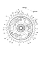
- FIG. 1 is a cross-sectional view illustrating a valve timing adjustment device according to a first embodiment.
- FIG. 2 is a sectional view taken along line II-II of FIG.
- FIG. 3 is a sectional view showing a fluid control valve of the valve timing adjusting device according to the first embodiment;
- FIG. 4 is a perspective view showing an inner sleeve of the fluid control valve according to the first embodiment,
- FIG. 5 is a perspective view showing a retard supply check valve of the fluid control valve according to the first embodiment;
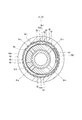
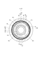
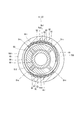
- FIG. 6 is a sectional view taken along line VI-VI in FIG. FIG.
- FIG. 7 is a cross-sectional view showing an initial state of a check valve of the fluid control valve according to the first embodiment
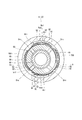
- FIG. 8 is a diagram showing an initial state of opening of a check valve of a fluid control valve according to a comparative embodiment
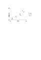
- FIG. 9 is a diagram illustrating a relationship between a flow rate of hydraulic oil and a pressure loss at an early stage of opening of the check valves according to the first embodiment and the comparative embodiment.
- FIG. 10 is a diagram illustrating the relationship between the flow rate of hydraulic oil and the pressure loss when a predetermined time has elapsed after the check valves of the first embodiment and the comparative embodiment have opened and the flow rate of hydraulic oil has become constant;
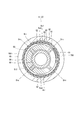
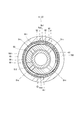
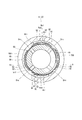
- FIG. 11 is a cross-sectional view illustrating a check valve and a displacement restricting unit of the fluid control valve according to the second embodiment
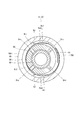
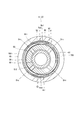
- FIG. 12 is a cross-sectional view illustrating a check valve and a displacement restricting unit of the fluid control valve according to the third embodiment
- FIG. 13 is a cross-sectional view illustrating a check valve and a displacement restricting unit of a fluid control valve according to a fourth embodiment
- FIG. 14 is a cross-sectional view illustrating a check valve and a displacement restricting unit of a fluid control valve according to a fifth embodiment
- FIG. 15 is a cross-sectional view illustrating a check valve and a displacement restricting unit of a fluid control valve according to a sixth embodiment
- FIG. 16 is a cross-sectional view illustrating a check valve and a displacement restricting unit of a fluid control valve according to a seventh embodiment
- FIG. 17 is a cross-sectional view illustrating a check valve and a displacement restricting unit of the fluid control valve according to the eighth embodiment.
- substantially the same components are denoted by the same reference numerals, and description thereof will be omitted.
- substantially the same component has the same or similar operation and effect.
- FIGS. 1 and 2 show a fluid control valve according to a first embodiment and a valve timing adjusting device to which the fluid control valve is applied.
- the valve timing adjusting device 10 changes the rotation phase of the camshaft 3 with respect to the crankshaft 2 of the engine 1 as an internal combustion engine, thereby changing the rotation of the camshaft 3 to open or close the intake valve 4 or the exhaust valve 5 of the intake valve 4. This is for adjusting the valve timing.
- the valve timing adjusting device 10 is provided in a power transmission path from the crankshaft 2 to the camshaft 3.
- the crankshaft 2 corresponds to a “drive shaft”.
- the camshaft 3 corresponds to a “driven shaft”.
- the intake valve 4 and the exhaust valve 5 correspond to “valves”.
- the valve timing adjustment device 10 includes a phase conversion unit PC, a hydraulic oil supply source OS as a fluid supply source, a hydraulic oil control unit OC, an oil discharge unit OD, a retard supply oil passage RRs, an advance supply oil passage RAs, and drain oil. There are a retard drain oil passage RRd, an advance drain oil passage RAd, and the like as paths.
- the phase converter PC includes the housing 20 and the vane rotor 30.
- the housing 20 has a gear part 21 and a case 22.
- the case 22 has a tubular portion 221 and plate portions 222 and 223.
- the tubular portion 221 is formed in a tubular shape.
- the plate portion 222 is formed integrally with the tubular portion 221 so as to close one end of the tubular portion 221.
- the plate portion 223 is provided to close the other end of the cylindrical portion 221. Thereby, a space 200 is formed inside the housing 20.
- the plate portion 223 is fixed to the cylindrical portion 221 by the bolt 12.
- the gear portion 21 is formed on the outer edge of the plate portion 223.
- the plate portion 223 is fitted to the end of the camshaft 3.
- the camshaft 3 rotatably supports the housing 20.
- the chain 6 is wound around the gear portion 21 and the crankshaft 2.
- the gear unit 21 rotates in conjunction with the crankshaft 2.
- the case 22 forms a plurality of partition portions 23 that protrude radially inward from the cylindrical portion 221. In the center of the plate portion 222 of the case 22, an opening 24 that opens to a space outside the case 22 is formed.
- the opening 24 is located on the opposite side of the vane rotor 30 from the camshaft 3.
- the vane rotor 30 has a boss 31 and a plurality of vanes 32.
- the boss 31 has a cylindrical shape and is fixed to an end of the camshaft 3.
- the vanes 32 protrude from the bosses 31 between the partition portions 23 radially outward.
- a space 200 inside the housing 20 is partitioned by a vane 32 into a retard chamber 201 and an advance chamber 202. That is, the housing 20 forms the retard chamber 201 and the advance chamber 202 between the housing 20 and the vane rotor 30.
- the retard chamber 201 is located on one side in the circumferential direction with respect to the vane 32.
- the advance chamber 202 is located on the other side in the circumferential direction with respect to the vane 32.
- the vane rotor 30 relatively rotates in the retard direction or the advance direction with respect to the housing 20 in accordance with the oil pressure of the working oil supplied to the retard chamber 201 and the advance chamber 202.
- the retard chamber 201 and the advance chamber 202 correspond to a “hydraulic chamber” as a fluid supply target.
- the hydraulic oil control valve 11 as a fluid control valve corresponds to the hydraulic oil control unit OC.
- the hydraulic oil control valve 11 includes a sleeve 400, a spool 60, a recycle oil passage Rre, a retard supply check valve 71, an advance supply check valve 72, a recycle check valve 81 as a check valve, a displacement regulating section 90, and the like. .
- the hydraulic oil control valve 11 is provided at the center of the housing 20 and the vane rotor 30, that is, at the center of the phase converter PC (see FIGS. 1 and 2).
- the hydraulic oil control valve 11 is provided so that at least a part thereof is located inside the housing 20.
- the hydraulic oil control valve 11 is located on the rotation axis of the phase converter PC.
- the sleeve 400 has an outer sleeve 40 as an outer cylinder and an inner sleeve 50 as an inner cylinder.
- the outer sleeve 40 is formed in a substantially cylindrical shape from a material having relatively high hardness including, for example, iron.
- the outer peripheral wall of the outer sleeve 40 has a substantially cylindrical shape.
- a screw portion 41 is formed on the outer peripheral wall at one end of the outer sleeve 40.
- a locking portion 49 extending annularly outward from the outer peripheral wall in the radial direction is formed.
- a shaft hole 100 and a supply hole 101 are formed at the end of the cam shaft 3 on the valve timing adjusting device 10 side.
- the shaft hole 100 is formed to extend in the axial direction of the camshaft 3 from the center of the end face of the camshaft 3 on the valve timing adjusting device 10 side.
- the supply hole 101 extends radially inward from the outer wall of the camshaft 3 and communicates with the shaft hole 100 (see FIG. 1).
- a shaft-side screw portion 110 that can be screw-coupled to the screw portion 41 of the outer sleeve 40 is formed.
- the outer sleeve 40 passes through the inside of the boss 31 of the vane rotor 30 and is fixed to the camshaft 3 such that the screw portion 41 is coupled to the shaft-side screw portion 110 of the camshaft 3.
- the locking portion 49 locks the end surface of the boss 31 of the vane rotor 30 on the side opposite to the cam shaft 3.
- the vane rotor 30 is fixed to the camshaft 3 so as to be sandwiched between the camshaft 3 and the locking portion 49.
- the outer sleeve 40 is provided at the center of the vane rotor 30.
- the hydraulic oil supply source OS is the oil pump 8.
- the oil discharge section OD is an oil pan 7.
- the oil pump 8 is connected to the supply hole 101.
- the oil pump 8 pumps up the working oil stored in the oil pan 7 and supplies it to the supply hole 101. As a result, the working oil flows into the shaft hole 100.
- the inner sleeve 50 is formed in a substantially cylindrical shape from a material having relatively low hardness including, for example, aluminum. That is, the inner sleeve 50 is formed of a material having a lower hardness than the outer sleeve 40.
- the inner sleeve 50 has an inner peripheral wall and an outer peripheral wall formed in a substantially cylindrical surface shape.
- the inner sleeve 50 has a surface subjected to a surface hardening treatment such as alumite, and has a surface layer having a higher hardness than the base material.
- the inner sleeve 50 is provided inside the outer sleeve 40 such that the outer peripheral wall is fitted to the inner peripheral wall of the outer sleeve 40.
- the inner sleeve 50 cannot move relative to the outer sleeve 40.
- a sleeve sealing portion 51 is provided at one end of the inner sleeve 50. The sleeve sealing portion 51 covers one end of the inner sleeve 50.
- the spool 60 is formed in a substantially cylindrical shape by, for example, metal.
- the spool 60 is provided inside the inner sleeve 50 so that the outer peripheral wall slides on the inner peripheral wall of the inner sleeve 50 and can reciprocate in the axial direction. That is, the spool 60 is provided inside the inner sleeve 50 so as to be relatively movable in the axial direction with respect to the inner sleeve 50.
- a spool sealing portion 62 is provided at one end of the spool 60. The spool sealing portion 62 closes one end of the spool 60.
- variable volume space Sv is formed inside the inner sleeve 50 between the sleeve sealing portion 51 and the other end of the spool 60.
- the volume of the variable volume space Sv changes when the spool 60 moves in the axial direction with respect to the inner sleeve 50. That is, the sleeve sealing portion 51 forms a volume variable space Sv in which the volume changes between the sleeve 60 and the spool 60.
- a spring 63 is provided in the variable volume space Sv.
- the spring 63 is a so-called coil spring, one end of which contacts the sleeve sealing portion 51, and the other end of which contacts the other end of the spool 60.
- the spring 63 urges the spool 60 to the side opposite to the sleeve sealing portion 51.
- a locking portion 59 is provided radially inside the other end of the outer sleeve 40.
- the locking portion 59 is formed in a bottomed cylindrical shape, and is provided so that the outer peripheral wall is fitted to the inner peripheral wall of the outer sleeve 40.
- a hole is formed in the center of the bottom of the locking portion 59, and the spool sealing portion 62 is located inside the hole.
- the locking portion 59 can lock one end of the spool 60 by the bottom.
- the locking portion 59 can restrict the movement of the spool 60 to the opposite side of the spool 60 from the sleeve sealing portion 51.
- the spool 60 is prevented from falling off from the inner side of the inner sleeve 50.
- the spool 60 is axially movable from a position where it contacts the locking portion 59 to a position where it contacts the sleeve sealing portion 51.
- the movable range with respect to the sleeve 400 is from the position where it contacts the locking portion 59 (see FIG. 3) to the position where it contacts the sleeve sealing portion 51.
- the movable range of the spool 60 is referred to as a “stroke section”.
- the outer end of the inner sleeve 50 on the side of the sleeve sealing portion 51 is formed smaller than the inner diameter of the outer sleeve 40.
- a cylindrical space St1 which is a substantially cylindrical space, is formed between the outer peripheral wall at the end of the inner sleeve 50 on the side of the sleeve sealing portion 51 and the inner peripheral wall of the outer sleeve 40.
- the inner sleeve 50 has an annular recess Ht.
- the annular concave portion Ht is formed so as to be annularly concave radially inward from a position corresponding to the locking portion 49 on the outer peripheral wall of the inner sleeve 50.
- an annular space St2 which is an annular space, is formed between the annular concave portion Ht and the inner peripheral wall of the outer sleeve 40.
- a flow channel groove 52 is formed in the inner sleeve 50.
- the flow channel groove 52 is formed so as to be recessed radially inward from the outer peripheral wall of the inner sleeve 50 and to extend in the axial direction of the inner sleeve 50 (see FIGS. 3, 4, and 6).
- Two channel grooves 52 are formed at equal intervals in the circumferential direction of the inner sleeve 50 (see FIG. 6).
- the flow channel groove 52 forms an axial supply oil passage RsA as an axial flow channel. That is, the axial supply oil passage RsA is formed to extend in the axial direction of the sleeve 400 at the interface T1 between the outer sleeve 40 and the inner sleeve 50.
- the axial supply oil passage RsA has one end connected to the cylindrical space St1, and the other end connected to the annular space St2.
- Regulation grooves 511 and 512 are formed in the inner sleeve 50.
- the regulating groove 511 is formed so as to be annularly recessed radially outward from a position corresponding to the end of the cylindrical space St1 on the inner peripheral wall of the inner sleeve 50.
- the restriction groove portion 512 is formed to be annularly concave radially outward from a position corresponding to the annular concave portion Ht on the inner peripheral wall of the inner sleeve 50.
- the inner sleeve 50 is provided with a movement restricting portion 513.
- the movement restricting portion 513 is formed so as to be annularly concave radially inward from the outer peripheral wall of the inner sleeve 50 between the restricting groove 511 and the restricting groove 512. Therefore, a part of the movement restricting portion 513 in the circumferential direction is connected to the flow channel groove 52.
- the movement restricting portion 513 forms an annular flow passage portion Rri. That is, the annular flow path portion Rri is formed between the outer sleeve 40 and the inner sleeve 50 so as to extend in the circumferential direction of the sleeve 400 while being connected to the axial supply oil passage RsA.
- the sleeve 400 has a retard supply opening ORs, an advance supply opening OAs, a retard opening OR, an advance opening OA, and a recycle opening Ore.
- the retard supply opening ORs is formed so as to extend in the radial direction of the sleeve 400 and connect the regulating groove 511 of the inner sleeve 50 to the cylindrical space St1 and the axial supply oil passage RsA. Note that a plurality of retard supply openings ORs are formed in the circumferential direction of the inner sleeve 50.
- the advance supply opening OAs is formed so as to extend in the radial direction of the sleeve 400 and connect the regulating groove 512 of the inner sleeve 50 to the annular space St2 and the axial supply oil passage RsA. Note that a plurality of advance angle supply openings OAs are formed in the circumferential direction of the inner sleeve 50.
- the retard opening OR extends in the radial direction of the sleeve 400 and connects the space inside the inner sleeve 50 and the space outside the outer sleeve 40. Note that a plurality of retard opening portions OR are formed in the circumferential direction of the sleeve 400.
- the retard opening OR communicates with the retard chamber 201 via the retard oil passage 301.
- the advance opening OA extends in the radial direction of the sleeve 400 and connects the space inside the inner sleeve 50 and the space outside the outer sleeve 40.
- the advance opening OA is formed on the locking portion 49 side with respect to the retard opening OR. Note that a plurality of advance opening portions OA are formed in the circumferential direction of the sleeve 400.
- the advance opening OA communicates with the advance chamber 202 via the advance oil passage 302.
- a substantially cylindrical valve seat surface 55 is formed in the movement restricting portion 513 of the inner sleeve 50 (see FIGS. 3 and 6). That is, the valve seat surface 55 is formed in a tubular shape on the inner sleeve 50 side of the annular flow path portion Rri.
- the recycle opening Ore is formed so as to extend in the radial direction of the sleeve 400 and communicate the valve seat surface 55 with the inside of the inner sleeve 50. That is, the recycle opening Ore connects the annular flow path Rri and the space inside the inner sleeve 50.
- Four recycling openings Ore are formed at equal intervals in the circumferential direction of the inner sleeve 50 (see FIG. 6).
- the recycle opening Ore corresponds to a “valve seat flow path”.
- the flow channel groove 52 and the axial supply oil passage RsA are formed between two adjacent recycle openings Ore in the circumferential direction of the sleeve 400 (see FIG. 6).
- the spool 60 has a retard supply recess HRs, a retard drain recess HRd, an advance drain recess HAd, an advance supply recess HAs, and drain openings Od1 and Od2.
- the retard supply recess HRs, the retard drain recess HRd, the advance drain recess HAd, and the advance supply recess HAs are each formed annularly so as to be recessed radially inward from the outer peripheral wall of the spool 60.
- the retard supply recess HRs, the retard drain recess HRd, the advance drain recess HAd, and the advance supply recess HAs are formed so as to be arranged in the axial direction of the spool 60 in this order.
- the retard drain recess HRd and the advance drain recess HAd are formed integrally.
- the retard drain recess HRd and the advance drain recess HAd form a specific space Ss with the inner peripheral wall of the inner sleeve 50. That is, the specific space Ss is formed between the spool 60 and the sleeve 400.
- the drain opening Od1 is formed so as to communicate a space inside the spool 60 with the retard drain recess HRd and the advance drain recess HAd, that is, the specific space Ss.
- the drain opening Od2 is formed at the end on the spool sealing portion 62 side of the spool 60 so as to communicate the inside space and the outside space.
- Two drain openings Od1 are formed at equal intervals in the circumferential direction of the spool 60, for example.
- the four drain openings Od2 are formed at equal intervals in the circumferential direction of the spool 60, for example.
- the retard supply oil passage RRs connects the oil pump 8 and the retard chamber 201 via the hydraulic oil control valve 11.
- the advance supply oil passage RAs connects the oil pump 8 and the advance chamber 202 via the hydraulic oil control valve 11.
- the retard drain oil passage RRd as the drain oil passage connects the retard chamber 201 and the oil pan 7.
- the advance drain oil passage RAd as the drain oil passage connects the advance chamber 202 and the oil pan 7.
- the retard supply oil passage RRs includes a supply hole 101, a shaft hole 100, a cylindrical space St1, an axial supply oil passage RsA, a retard supply opening ORs, a regulating groove 511, a retard supply recess HRs, and a retard opening.
- the oil pump 8 and the retard chamber 201 are connected via the section OR and the retard oil passage 301.
- the advancing supply oil passage RAs includes a supply hole 101, a shaft hole 100, a cylindrical space St1, an axial supply oil passage RsA, an advancing supply opening OAs, a regulating groove 512, an advancing supply recess HAs, and an advancing opening.
- the oil pump 8 and the advance chamber 202 are connected via the section OA and the advance oil passage 302.
- the retard drain oil passage RRd connects the retard chamber 201 and the oil pan 7 via the retard oil passage 301, the retard opening OR, the retard drain recess HRd, and the drain openings Od1 and Od2.
- the advancing drain oil passage RAd connects the advancing chamber 202 and the oil pan 7 via the advancing oil passage 302, the advancing opening OA, the advancing drain recess HAd, and the drain openings Od1 and Od2.
- the retard supply oil passage RRs, the advance supply oil passage RAs, the retard drain oil passage RRd, and the advance drain oil passage RAd are partially formed inside the hydraulic oil control valve 11.
- the axial supply oil passage RsA is formed to extend in the axial direction of the sleeve 400 in the advance supply oil passage RAs. That is, the sleeve 400 has the axial supply oil passage RsA extending in the axial direction of the sleeve 400 in the advance supply oil passage RAs.
- the recycle oil passage Rre connects the retarded drain oil passage RRd and the advanced drain oil passage RAd as the drain oil passage to the retarded supply oil passage RRs and the advanced supply oil passage RAs.
- the recycle oil passage Rre extends from the specific space Ss via the recycle opening Ore, the movement restricting portion 513, the annular flow passage Rri, and the retard supply oil passage RRs and the advance supply oil passage RAs. That is, it is connected to the axial supply oil passage RsA.
- the retard drain oil passage RRd and the advance drain oil passage RAd as the drain oil passage include a retard oil passage 301, a retard opening OR, an advance oil passage 302, an advance opening OA, a specific space Ss, and a drain opening. It is connected to the space inside the spool 60 via the section Od1.
- the drain opening Od1 is formed to be connected to the specific space Ss in the drain oil passage and to extend from the specific space Ss in the radial direction of the sleeve 400 or the spool 60.
- the recycle opening Ore is formed so as to be connected to the specific space Ss in the recycle oil passage Rre and extend from the specific space Ss to a side opposite to the drain opening Od1.
- the recycled oil passage Rre is connected to the retarded drain oil passage RRd and the advanced drain oil passage RAd in the specific space Ss.
- the drain opening Od1 is formed so that at least a part thereof overlaps the recycle opening Ore in the axial direction of the sleeve 400 or the spool 60.
- the drain opening Od1 is formed in the spool 60 so as to extend from the specific space Ss to the sleeve 400 or the inside of the spool 60 in the radial direction.
- the recycle opening Ore is formed in the inner sleeve 50 so as to extend from the specific space Ss to the outside in the radial direction of the sleeve 400 or the spool 60.
- the oil pump 8 includes a supply hole 101, a shaft hole 100, a cylindrical space St1, an axial supply oil passage RsA, a retard supply opening ORs, a restriction groove 511, a retard supply recess HRs of the retard supply oil passage RRs. , And communicates with the retard chamber 201 via the retard opening OR and the retard oil passage 301. Thereby, hydraulic oil can be supplied from the oil pump 8 to the retard chamber 201 via the retard supply oil passage RRs.
- the advance chamber 202 is connected to the oil pan 7 via the advance oil passage 302 of the advance drain oil passage RAd, the advance opening OA, the advance drain recess HAd, and the drain openings Od1 and Od2. Communicate. Thereby, the working oil can be discharged from the advance chamber 202 to the oil pan 7 via the advance drain oil passage RAd.
- the oil pump 8 supplies the advance supply oil passage RAs.
- the hole 101, the shaft hole 100, the cylindrical space St1, the axial supply oil passage RsA, the advance supply opening OAs, the regulating groove 512, the advance supply recess HAs, the advance opening OA, and the advance oil passage 302 It communicates with the advancing chamber 202 via the control unit.
- the oil pump 8 and the retard chamber 201 communicate with each other through the retard supply oil passage RRs.
- hydraulic oil can be supplied from the oil pump 8 to the retard chamber 201 and the advance chamber 202 via the retard supply oil path RRs and the advance supply oil path RAs.
- the hydraulic oil flows from the retard chamber 201 and the advance chamber 202 to the oil pan 7 because the retard drain oil passage RRd and the advance drain oil passage RAd are closed by the spool 60, that is, shut off. Not emitted.
- the retard chamber 201 becomes the retard oil passage 301 of the retard drain oil passage RRd.
- the oil pan 7 communicates with the oil pan 7 through the retard opening OR, the retard drain recess HRd, and the drain openings Od1 and Od2.
- the oil pump 8 and the advance chamber 202 communicate with each other through the advance supply oil passage RAs.
- hydraulic oil can be discharged from the retard chamber 201 to the oil pan 7 via the retard drain oil passage RRd, and the advance chamber 202 from the oil pump 8 via the advance supply oil passage RAs. Can be supplied with hydraulic oil.
- a filter 58 is provided inside the end of the outer sleeve 40 on the sleeve sealing portion 51 side, that is, in the middle of the retard supply oil passage RRs and the advance supply oil passage RAs.
- the filter 58 is, for example, a disk-shaped mesh.
- the filter 58 is capable of collecting foreign substances contained in the hydraulic oil. Therefore, it is possible to suppress the foreign matter from flowing on the downstream side of the filter 58, that is, on the side opposite to the oil pump 8.
- the retard supply check valve 71 is formed in a substantially cylindrical shape by bending, for example, a rectangular thin metal plate so that the longitudinal direction is along the circumferential direction. That is, the retard supply check valve 71 is formed of an annular elastic body.
- FIG. 5 is a perspective view of the retard supply check valve 71.
- the retard supply check valve 71 has an overlapping portion 700.
- the overlap portion 700 is formed at one end in the circumferential direction of the retard supply check valve 71.
- the overlapping portion 700 is formed so as to overlap the other end of the retard supply check valve 71 in the circumferential direction in the radial direction (see FIG. 5).
- the retard supply check valve 71 is provided in the regulating groove 511.
- the retard supply check valve 71 is provided in the regulating groove 511 so as to be elastically deformable in the radial direction.
- the retard supply check valve 71 is provided radially inside the inner sleeve 50 with respect to the retard supply opening ORs.
- the retard supply check valve 71 is provided in the regulating groove portion 511, and in a state where hydraulic oil is not flowing through the retard supply oil passage RRs, that is, in a state where no external force is acting, the overlapping portion 700 is the other in the circumferential direction. It is in a state where it overlaps the end.
- the retard supply check valve 71 When the hydraulic oil flows from the retard supply opening ORs to the retard supply recess HRs in the retard supply oil passage RRs, the retard supply check valve 71 is configured such that the outer peripheral wall is pushed by the hydraulic oil and contracts radially inward. That is, it is deformed so as to reduce the diameter. Thereby, the outer peripheral wall of the retard supply check valve 71 is opened by separating from the retard supply opening ORs, and the hydraulic oil flows to the retard supply recess HRs through the retard supply check valve 71. be able to. At this time, the overlapping portion 700 is in a state in which the overlapping portion 700 and the other end of the retard supply check valve 71 maintain a partially overlapping state while increasing the length of the overlapping range.
- the retard supply check valve 71 When the flow rate of the hydraulic oil flowing through the retard supply oil passage RRs becomes equal to or less than a predetermined value, the retard supply check valve 71 is deformed so as to expand radially outward, that is, expand. Further, when the hydraulic oil flows from the retard supply concave portion HRs to the retard supply opening ORs, the inner peripheral wall of the retard supply check valve 71 is pushed radially outward by the hydraulic oil, and the retard supply check valve 71 is moved to the retard supply opening ORs. The valve is closed by contact. This restricts the flow of the hydraulic oil from the retard supply recess HRs to the retard supply opening ORs.
- the retard supply check valve 71 functions as a check valve, permits the flow of hydraulic oil from the retard supply opening ORs to the retard supply recess HRs, and allows the hydraulic oil to flow from the retard supply recess HRs.
- the flow of the hydraulic oil to the retard supply opening ORs side can be regulated. That is, the retard supply check valve 71 is provided on the oil pump 8 side with respect to the spool 60 of the hydraulic oil control valve 11 in the retard supply oil passage RRs, and the hydraulic oil flows from the oil pump 8 side to the retard chamber 201 side. Only flow is allowed.
- the advance supply check valve 72 is formed in a substantially cylindrical shape by, for example, bending a rectangular thin metal plate so that its longitudinal direction is along the circumferential direction.
- the configuration of the advance angle supply check valve 72 is the same as that of the retard angle supply check valve 71, and a detailed description of the configuration is omitted.
- Advance supply check valve 72 is provided in regulating groove 512.
- the advance angle supply check valve 72 is provided in the regulating groove portion 512 so as to be elastically deformable in the radial direction.
- the advance angle supply check valve 72 is provided radially inside the inner sleeve 50 with respect to the advance angle supply opening OAs.
- the advance angle supply check valve 72 is provided in the regulating groove portion 512, and in a state where hydraulic oil does not flow through the advance angle supply oil passage RAs, that is, in a state where no external force is acting, the overlap portion 700 is positioned on the other side in the circumferential direction. It is in a state where it overlaps the end.
- the advance supply check valve 72 is configured such that the outer peripheral wall is pushed by the hydraulic oil and contracts radially inward. That is, it is deformed so as to reduce the diameter.
- the outer peripheral wall of the advance supply check valve 72 is opened by separating from the advance supply opening OAs, and the hydraulic oil flows through the advance supply check valve 72 to the advance supply recess HAs side. be able to.
- the overlapping portion 700 is in a state where the overlapping portion 700 and the other end of the advance supply check valve 72 maintain a partially overlapping state while increasing the length of the overlapping range.
- the advance supply check valve 72 When the flow rate of the working oil flowing through the advance supply oil passage RAs becomes equal to or less than a predetermined value, the advance supply check valve 72 is deformed so as to expand radially outward, that is, expand. Further, when the hydraulic oil flows from the advance supply concave portion HAs to the advance supply opening OAs, the inner peripheral wall of the advance supply check valve 72 is pushed radially outward by the hydraulic oil, and is moved into the advance supply opening OAs. The valve is closed by contact. This restricts the flow of the hydraulic oil from the advance supply recess HAs to the advance supply opening OAs.
- the advance supply check valve 72 functions as a check valve, allows the flow of hydraulic oil from the advance supply opening OAs to the advance supply recess HAs, and allows the hydraulic oil to flow from the advance supply recess HAs.
- the flow of the hydraulic oil to the advance supply opening OAs side can be regulated. That is, the advance supply check valve 72 is provided on the oil pump 8 side with respect to the spool 60 of the hydraulic oil control valve 11 in the advance supply oil passage RAs, and the hydraulic oil flows from the oil pump 8 side to the advance chamber 202 side. Only flow is allowed.
- the recycle check valve 81 as a check valve is formed in a substantially cylindrical shape, for example, by bending a rectangular thin metal plate so that the longitudinal direction is along the circumferential direction. That is, the recycle check valve 81 is made of an annular elastic body.
- the outside diameter of the recycle check valve 81 is formed larger than the outside diameter of the retard supply check valve 71.
- the configuration of the recycle check valve 81 is the same as that of the retard supply check valve 71 except for the difference in the outer diameter, and thus the detailed description of the configuration is omitted.
- the recycle check valve 81 is provided on the recycle oil passage Rre in the movement restricting portion 513, that is, in the annular flow passage portion Rri.
- the recycle check valve 81 is provided so as to be elastically deformable in the radial direction in the annular flow path portion Rri.
- the recycle check valve 81 is provided radially outside the inner sleeve 50 with respect to the valve seat surface 55.
- the recycle check valve 81 is provided in the annular flow path portion Rri, and when the operating oil is not flowing through the recycle oil passage Rre, that is, in a state in which no external force is applied, the overlapping portion 700 is connected to the other end in the circumferential direction. (See FIG. 6).
- the recycle check valve 81 When the hydraulic oil flows from the recycle opening Ore side to the annular flow path Rri side in the recycle oil passage Rre, the recycle check valve 81 is expanded such that the inner peripheral wall is pushed radially outward by the hydraulic oil, that is, expands in diameter. In this way. Thereby, the inner peripheral wall of the recycle check valve 81 is opened by separating from the valve seat surface 55, and the hydraulic oil can flow toward the annular flow path portion Rri via the recycle check valve 81 (FIG. 7). reference). At this time, the overlapping portion 700 is in a state where the overlapping portion 700 and the other end of the recycle check valve 81 maintain a partially overlapping state while reducing the length of the overlapping range.
- the recycle check valve 81 functions as a check valve, permits the flow of hydraulic oil from the recycle opening Ore side to the annular flow path Rri side, and allows the recycle check valve 81 to recycle from the annular flow path Rri side.
- the flow of hydraulic oil to the side can be regulated. That is, the recycle check valve 81 allows only the flow of the hydraulic oil from the drain oil passage side to the retard supply oil passage RRs side and the advance supply oil passage RAs side in the recycle oil passage Rre.
- the movement restricting unit 513 can restrict the movement of the recycle check valve 81 in the axial direction.
- the displacement regulating section 90 has a regulating section main body 91 and a regulating section flow path 92 (see FIG. 6).
- the restricting portion main body 91 is formed, for example, by bending a bellows-like plate material in an annular shape.
- the regulating portion main body 91 is formed in a substantially cylindrical shape from a plate material such as a metal.
- the restricting portion main body 91 is provided outside the recycle check valve 81 in the annular flow path portion Rri.
- the axial length of the restricting portion main body 91 is substantially the same as the axial length of the recycle check valve 81.
- the outer edge of the regulating portion main body 91 can abut on the inner peripheral wall of the outer sleeve 40.
- the regulating portion main body 91 can restrict the displacement of the recycle check valve 81 in the diameter increasing direction by the inner edge abutting on the outer peripheral wall of the recycle check valve 81. (See FIG. 7).
- the regulation part main body 91 is formed so as to be elastically deformable in the radial direction of the annular flow path part Rri.
- the regulating portion main body 91 is formed of a bellows-like plate, a plurality of regulating portion flow paths 92 are formed inside and outside the regulating portion main body 91 (see FIGS. 6 and 7).
- the regulating portion flow path 92 is formed so as to communicate one side and the other side of the regulating portion main body 91 in the axial direction of the sleeve 400 so that the hydraulic oil can flow.
- at least a part of the regulating portion main body 91 is located at a connection point Rc1 between the annular flow passage portion Rri and the axial supply oil passage RsA. Therefore, the hydraulic oil flowing through the axial supply oil passage RsA can flow through the restriction portion flow path 92, and the flow of the hydraulic oil is prevented from being hindered by the displacement restriction portion 90 provided in the annular flow path portion Rri.
- FIG. 8 shows a fluid control valve according to a comparative embodiment.
- the fluid control valve according to the comparative embodiment has the same configuration as the hydraulic oil control valve 11 according to the present embodiment except that the fluid control valve does not include the displacement restricting unit 90. Since the fluid control valve according to the comparative example does not include the displacement restricting portion 90, when the diameter of the recycle check valve 81 is increased and the valve is opened (see FIG. 8), the recycle check valve 81 may be excessively deformed and damaged. Further, in the initial stage of opening the recycle check valve 81 (see FIG. 8), there is a possibility that pressure loss due to uneven opening of the recycle check valve 81 in the circumferential direction may increase.
- the hydraulic oil control valve 11 of the present embodiment includes the displacement restricting portion 90, when the recycle check valve 81 expands in diameter and opens (see FIG. 7), excessive deformation of the recycle check valve 81 is suppressed. Thus, damage to the recycle check valve 81 can be suppressed. Further, in the initial stage of opening the recycle check valve 81 (see FIG. 7), uneven opening of the recycle check valve 81 in the circumferential direction can be suppressed, and the pressure loss can be reduced.
- FIG. 9 is a diagram showing experimental results of the present embodiment and the comparative embodiment regarding the relationship between the flow rate of hydraulic oil and the pressure loss at the initial stage of opening of the recycle check valve 81.
- P0 indicates the experimental result of the comparative embodiment
- P1 indicates the experimental result of the present embodiment.
- the pressure loss of the present embodiment is smaller than that of the comparative embodiment regardless of the flow rate of the hydraulic oil.
- FIG. 10 shows the experimental results of the present embodiment and the comparative embodiment regarding the relationship between the flow rate of the hydraulic oil and the pressure loss when a predetermined time has elapsed since the recycle check valve 81 was opened and the flow rate of the hydraulic oil became constant.
- P0 indicates the experimental result of the comparative embodiment
- P1 indicates the experimental result of the present embodiment.
- FIG. 10 when a predetermined time has elapsed after the recycle check valve 81 has been opened and the flow rate of the hydraulic oil has become constant, it is understood that there is no difference in pressure loss between the comparative embodiment and the present embodiment. .
- the present embodiment has a high effect of suppressing the pressure loss of the hydraulic oil particularly in the early stage of opening the recycle check valve 81.
- a linear solenoid 9 is provided on the side of the spool 60 opposite to the camshaft 3.
- the linear solenoid 9 is provided so as to contact the spool sealing portion 62.
- the linear solenoid 9 presses the spool 60 toward the camshaft 3 via the spool sealing portion 62 against the urging force of the spring 63. Accordingly, the position of the spool 60 in the axial direction with respect to the sleeve 400 changes in the stroke section.
- variable volume space Sv communicates with the retard drain oil passage RRd and the advance drain oil passage RAd. Therefore, the variable volume space Sv is open to the atmosphere via the drain opening Od2 of the retard drain oil passage RRd and the advance drain oil passage RAd. Thereby, the pressure in the variable volume space Sv can be made equal to the atmospheric pressure. Therefore, the axial movement of the spool 60 can be made smooth.
- the hydraulic oil is delayed from the oil pump 8 via the retard supply oil passage RRs. It is supplied to the corner chamber 201. At this time, the hydraulic oil is discharged from the advance chamber 202 to the oil pan 7 via the advance drain oil passage RAd. Further, part of the hydraulic oil flowing through the advance drain oil passage RAd is returned to the axial supply oil passage RsA and the retard supply oil passage RRs via the recycle oil passage Rre. Thereby, the operating oil discharged from the advance chamber 202 can be reused. At this time, the recycle check valve 81 suppresses the backflow of the recycled oil passage Rre from the axial supply oil passage RsA to the drain oil passage.
- the hydraulic oil is supplied from the oil pump 8 to the retard supply oil passage. It is supplied to the retard chamber 201 via RRs. At this time, the hydraulic oil is supplied from the oil pump 8 to the advance chamber 202 via the advance supply oil passage RAs. At this time, since the retard drain oil passage RRd and the advance drain oil passage RAd are closed by the spool 60, the hydraulic oil does not flow through the drain oil passage, and the hydraulic oil flows through the recycle oil passage Rre. It is not returned to the direction supply oil passage RsA side.
- the hydraulic oil is supplied from the oil pump 8 via the advance supply oil passage RAs. It is supplied to the advance chamber 202. At this time, the hydraulic oil is discharged from the retard chamber 201 to the oil pan 7 via the retard drain oil passage RRd. Further, a part of the hydraulic oil flowing through the retard drain oil passage RRd is returned to the axial supply oil passage RsA and the advance supply oil passage RAs via the recycle oil passage Rre. Thereby, the hydraulic oil discharged from the retard chamber 201 can be reused. At this time, the recycle check valve 81 suppresses the backflow of the recycled oil passage Rre from the axial supply oil passage RsA to the drain oil passage.
- This embodiment further includes a lock pin 33 (see FIGS. 1 and 2).
- the lock pin 33 is formed in a cylindrical shape with a bottom, and is housed in a housing hole 321 formed in the vane 32 so as to be able to reciprocate in the axial direction.
- a spring 34 is provided inside the lock pin 33. The spring 34 urges the lock pin 33 toward the plate portion 222 of the case 22.
- a fitting recess 25 is formed on the vane 32 side of the plate portion 222 of the case 22.
- the lock pin 33 can be fitted into the fitting recess 25 when the vane rotor 30 is at the most retarded position with respect to the housing 20.
- the lock pin 33 is fitted in the fitting recess 25, the relative rotation of the vane rotor 30 with respect to the housing 20 is restricted.
- the lock pin 33 is not fitted in the fitting recess 25, the relative rotation of the vane rotor 30 with respect to the housing 20 is allowed.
- a pin control oil passage 304 communicating with the advance chamber 202 is formed between the lock pin 33 of the vane 32 and the advance chamber 202 (see FIG. 2).
- the pressure of the operating oil flowing into the pin control oil passage 304 from the advance chamber 202 acts in a direction in which the lock pin 33 comes out of the fitting recess 25 against the urging force of the spring 34.
- valve timing adjusting device 10 configured as described above, when hydraulic oil is supplied to the advance chamber 202, hydraulic oil flows into the pin control oil passage 304, the lock pin 33 comes out of the fitting recess 25, and the housing The state is such that the relative rotation of the vane rotor 30 with respect to 20 is allowed.
- the valve timing adjusting device 10 presses the spool 60 of the hydraulic oil control valve 11 by driving the linear solenoid 9, and connects the hydraulic oil control valve 11 to the advance chamber 202 while connecting the oil pump 8 and the retard chamber 201.
- the operating oil is supplied from the advance chamber 202 to the oil pan 7 via the advance drain oil passage RAd while the operating oil is supplied to the retard chamber 201 via the retard supply oil passage RRs. Will be returned. Further, the working oil is returned from the advance drain oil passage RAd to the retard supply oil passage RRs via the recycle oil passage Rre.
- the operating oil is supplied from the retard chamber 201 to the oil pan 7 via the retard drain oil passage RRd while the operating oil is supplied to the advance chamber 202 via the advance supply oil passage RAs. Will be returned. Further, the working oil is returned from the retard drain oil passage RRd to the advance supply oil passage RAs via the recycle oil passage Rre.
- the valve timing adjusting device 10 sets the hydraulic oil control valve 11 to the first operating state when the rotation phase of the camshaft 3 is on the advanced side of the target value.
- the vane rotor 30 relatively rotates in the retard direction with respect to the housing 20, and the rotational phase of the cam shaft 3 changes to the retard side.
- the hydraulic oil control valve 11 when the hydraulic oil control valve 11 is in the first operating state or the second operating state, the hydraulic oil control valve 11 passes through the recycle oil passage Rre from the drain oil passage to the retard supply oil passage RRs or the advance supply oil passage RAs. The hydraulic oil is returned to. Thereby, the operating oil discharged from the advance chamber 202 or the retard chamber 201 can be reused.
- the hydraulic oil control valve 11 even when the hydraulic oil control valve 11 is in the phase holding state, that is, when the phase of the phase conversion unit PC is being held, the hydraulic oil is supplied to the retard chamber 201 and the advance chamber 202. Can be supplied.
- the phase of the phase converter PC when the phase of the phase converter PC is maintained, the supply state of the hydraulic oil to the retard chamber 201 and the advance chamber 202 is maintained, and the phase converter generated by the air being sucked into the retard chamber 201 and the advance chamber 202 is generated.
- the PC can be prevented from being out of phase.
- the hydraulic oil control valve 11 of the present embodiment is suitable for the valve timing adjusting device 10 in which the initial state of the recycle check valve 81 is repeated.
- the hydraulic oil control valve 11 is provided so as to be located at the center of the phase converter PC, that is, on the rotation axis of the phase converter PC. Therefore, when the engine 1 is operating, centrifugal force acts on the recycle check valve 81, and the position of the recycle check valve 81 and the on-off valve in the annular flow path Rri may become unstable. However, in the present embodiment, the position of the recycle check valve 81 and the on-off valve in the annular flow path portion Rri can be stabilized by the displacement restricting portion 90.
- the present embodiment is a hydraulic oil control valve 11 that can control the flow of hydraulic oil supplied from a hydraulic oil supply source OS to a hydraulic chamber as a fluid supply target, and an outer cylinder as an outer cylinder.
- An opening Ore, a recycle check valve 81 as a check valve, and a displacement restricting section 90 are provided.
- the inner sleeve 50 is provided inside the outer sleeve 40.
- the axial supply oil passage RsA is provided between the outer sleeve 40 and the inner sleeve 50 so that hydraulic oil flowing from the hydraulic oil supply source OS to the retard chamber 201 and the advance chamber 202 as hydraulic chambers can flow.
- 40 and the inner sleeve 50 are formed to extend in the axial direction.
- the annular flow path portion Rri is formed in an annular shape so as to extend in the circumferential direction of the outer sleeve 40 and the inner sleeve 50 while being connected to the axial supply oil passage RsA between the outer sleeve 40 and the inner sleeve 50.
- the valve seat surface 55 is formed in a tubular shape on the inner sleeve 50 side of the annular flow path portion Rri.
- the recycle opening Ore communicates the valve seat surface 55 with the inside of the inner sleeve 50.
- the recycle check valve 81 is formed of an annular elastic body, is provided in the annular flow path portion Rri, and opens when the diameter increases and is separated from the valve seat surface 55 to open from the recycle opening portion Ore side to the annular flow passage portion Rri side.
- the flow of hydraulic oil is permitted, the diameter of the hydraulic oil is reduced, and the valve closes by contacting the valve seat surface 55 to restrict the flow of hydraulic oil from the annular flow path portion Rri to the recycle opening Ore.
- the displacement regulating portion 90 is provided with a regulating portion main body 91 provided outside the recycle check valve 81 in the annular flow passage portion Rri so as to regulate the displacement of the recycle check valve 81 in the radial direction, and the hydraulic oil can flow therethrough.
- a regulating portion flow path 92 that communicates between one side and the other side of the regulating portion main body 91.
- the displacement of the recycle check valve 81 in the radial direction can be regulated by the regulating portion main body 91 of the displacement regulating portion 90. Therefore, damage due to excessive deformation of the recycle check valve 81 can be suppressed.
- the displacement restricting portion 90 has a restricting portion flow path 92 that connects one side and the other side of the restricting portion main body 91 in the axial direction of the outer sleeve 40 and the inner sleeve 50 so that hydraulic oil can flow. . Therefore, the hydraulic oil flowing through the axial supply oil passage RsA can flow through the restriction portion flow path 92, and the flow of the hydraulic oil is prevented from being hindered by the displacement restriction portion 90 provided in the annular flow path portion Rri. Thus, it is possible to suppress a decrease in the flow rate of the working oil supplied to the retard chamber 201 and the advance chamber 202 as the hydraulic chamber.
- the restricting portion main body 91 is formed by bending a bellows-like plate material into an annular shape. Therefore, the displacement regulating portion 90 having the regulating portion flow path 92 can be formed relatively easily.
- the restricting portion main body 91 is formed so as to be elastically deformable in the radial direction of the annular flow path portion Rri. Therefore, the impact of the collision between the recycle check valve 81 and the restricting portion main body 91 when the displacement restricting portion 90 restricts the displacement of the recycle check valve 81 in the radial direction can be reduced. Thereby, abrasion and breakage of the recycle check valve 81 and the regulating portion main body 91 can be suppressed.
- the present embodiment further includes a spool 60.
- the spool 60 is provided inside the inner sleeve 50 so as to be relatively movable in the axial direction with respect to the inner sleeve 50, and the hydraulic oil supply source OS and the retard chamber 201 as a hydraulic chamber are provided in accordance with the axial position with respect to the inner sleeve 50.
- the flow of the hydraulic oil to the advance chamber 202 can be controlled.
- the inner sleeve 50, the recycle check valve 81, and the displacement restricting portion 90 do not move relative to the outer sleeve 40 when the flow of the hydraulic oil is controlled by the spool 60. Becomes stable.
- the present embodiment is a valve timing adjusting device 10 that adjusts the valve timing of the engine 1 and includes a phase conversion unit PC and a hydraulic oil control valve 11 as a hydraulic oil control valve.
- the phase converter PC is attached to the camshaft 3 of the engine 1 so as to be rotatable in conjunction with the crankshaft 2 of the engine 1, and has a retard chamber 201 and an advance chamber 202 as hydraulic chambers. 201, the phase of the crankshaft 2 and the phase of the camshaft 3 are converted by the hydraulic oil supplied to the advance chamber 202.
- the hydraulic oil control valve 11 controls the hydraulic oil supplied from the hydraulic oil supply source OS to the retard chamber 201 and the advance chamber 202.
- the displacement restricting section 90 can suppress the flow rate of the hydraulic oil supplied to the retard chamber 201 and the advance chamber 202 as hydraulic chambers, and can also prevent the recycle check valve 81 from being damaged.
- the hydraulic oil control valve 11 of the present embodiment is suitable for the valve timing adjusting device 10 in which the initial state of the recycle check valve 81 is repeated.
- the hydraulic oil control valve 11 is provided at the center of the phase conversion unit PC. Therefore, during operation of the engine 1, the recycle check valve 81 rotates, and centrifugal force acts on the recycle check valve 81, and the position of the recycle check valve 81 and the on-off valve in the annular flow path Rri may become unstable. is there. However, in the present embodiment, the position of the recycle check valve 81 and the on-off valve in the annular flow path portion Rri can be stabilized by the displacement restricting portion 90.
- FIG. 11 shows a fluid control valve according to the second embodiment.
- the second embodiment differs from the first embodiment in the configuration of the displacement restricting section 90.
- the restricting portion main body 91 is formed by further bending a spirally wound wire into an annular shape.
- the regulating portion main body 91 is formed by spirally winding a wire such as a metal into a coil shape, and further winding the wire in a ring shape.
- the regulating section main body 91 is provided outside the recycle check valve 81 in the annular flow path section Rri.
- the outer edge of the regulating portion main body 91 can abut on the inner peripheral wall of the outer sleeve 40.
- the regulating portion main body 91 can restrict the displacement of the recycle check valve 81 in the diameter increasing direction by the inner edge abutting on the outer peripheral wall of the recycle check valve 81.
- the regulation part main body 91 is formed so as to be elastically deformable in the radial direction of the annular flow path part Rri.
- the regulating portion main body 91 is formed of a spirally wound wire, a plurality of regulating portion flow paths 92 are formed in the regulating portion main body 91 (see FIG. 11).
- the regulating portion flow path 92 is formed so as to communicate one side and the other side of the regulating portion main body 91 in the axial direction of the sleeve 400 so that the hydraulic oil can flow.
- at least a part of the regulating portion main body 91 is located at a connection point Rc1 between the annular flow passage portion Rri and the axial supply oil passage RsA. Therefore, the hydraulic oil flowing through the axial supply oil passage RsA can flow through the regulating portion flow path 92, and is prevented from being obstructed by the displacement regulating portion 90 provided in the annular flow passage portion Rri.
- the restricting portion main body 91 is formed by further bending a spirally wound wire into an annular shape. Therefore, the displacement regulating portion 90 having the regulating portion flow path 92 can be formed relatively easily.
- FIG. 12 shows a fluid control valve according to the third embodiment.
- the third embodiment differs from the first embodiment in the configuration of the displacement restricting section 90.
- the regulating portion main body 91 is formed in a substantially cylindrical shape by, for example, metal.
- the restricting portion main body 91 is provided outside the recycle check valve 81 in the annular flow path portion Rri.
- the axial length of the restricting portion main body 91 is substantially the same as the axial length of the recycle check valve 81.
- the outer peripheral wall of the regulating portion main body 91 can abut on the inner peripheral wall of the outer sleeve 40.
- the regulating unit main body 91 can regulate the displacement of the recycle check valve 81 in the radial direction by contacting the inner peripheral wall with the outer peripheral wall of the recycle check valve 81. .
- the regulating portion flow path 92 is a hole that connects one end surface of the regulating portion main body 91 in the axial direction to the other end surface (see FIG. 12).
- a plurality of regulating section flow paths 92 are formed at regular intervals in the circumferential direction of the regulating section main body 91.
- the regulating portion flow path 92 is formed so as to communicate one side and the other side of the regulating portion main body 91 in the axial direction of the sleeve 400 so that the hydraulic oil can flow.
- at least a part of the regulating portion main body 91 is located at a connection point Rc1 between the annular flow passage portion Rri and the axial supply oil passage RsA. Therefore, the hydraulic oil flowing through the axial supply oil passage RsA can flow through the regulating portion flow path 92, and is prevented from being obstructed by the displacement regulating portion 90 provided in the annular flow passage portion Rri.
- the regulating portion flow path 92 is a hole that connects one end surface of the regulating portion main body 91 in the axial direction to the other end surface. Therefore, the displacement regulating portion 90 having the regulating portion flow path 92 can be formed relatively easily.
- FIG. 13 shows a fluid control valve according to the fourth embodiment.
- the fourth embodiment differs from the third embodiment in the configuration of the displacement restricting section 90.
- the regulating portion flow path 92 is a groove that connects one end surface of the regulating portion main body 91 in the axial direction to the other end surface (see FIG. 13).
- the regulating portion flow path 92 is formed so as to be recessed radially inward from the outer peripheral wall of the regulating portion main body 91.
- a plurality of regulating portion flow paths 92 are formed at regular intervals in the circumferential direction of the regulating portion main body 91.
- the restricting portion flow path 92 is formed so as to communicate one side and the other side of the restricting portion main body 91 in the axial direction of the sleeve 400 so that hydraulic oil can flow.
- the hydraulic oil flowing in the axial supply oil passage RsA can flow through the regulating portion flow path 92, and is prevented from being obstructed by the displacement regulating portion 90 provided in the annular flow passage portion Rri. Is done.
- the regulating portion flow path 92 is a groove that connects one end surface of the regulating portion main body 91 in the axial direction to the other end surface. Therefore, the displacement regulating portion 90 having the regulating portion flow path 92 can be formed relatively easily.
- FIG. 14 shows a fluid control valve according to the fifth embodiment.
- the fifth embodiment differs from the third embodiment in the configuration of the displacement restricting section 90.
- the regulating portion main body 91 is formed in a porous substantially cylindrical shape by, for example, sintering a metal or the like.
- the regulating portion main body 91 is formed in a porous shape, so that a large number of regulating portion flow paths 92 are formed in the regulating portion main body 91.
- the regulating portion flow path 92 is formed so as to communicate one side and the other side of the regulating portion main body 91 in the axial direction of the sleeve 400 so that the hydraulic oil can flow.
- the hydraulic oil flowing in the axial supply oil passage RsA can flow through the regulating portion flow path 92, and is prevented from being obstructed by the displacement regulating portion 90 provided in the annular flow passage portion Rri. Is done.
- the regulating portion flow path 92 is formed by forming the regulating portion main body 91 in a porous shape. Therefore, the displacement regulating portion 90 having the regulating portion flow path 92 can be formed relatively easily.
- FIG. 15 shows a fluid control valve according to the sixth embodiment.
- the sixth embodiment differs from the first embodiment in the configuration of the displacement restricting section 90.
- the restricting portion main body 91 is divided into two in the circumferential direction of the annular flow path portion Rri, and is formed in a substantially arc shape.
- the regulating part main body 91 divided into two is provided at a position corresponding to each of the two axial supply oil passages RsA.
- the regulating portion main body 91 divided into two is provided in the annular flow passage portion Rri so as to sandwich the shaft of the sleeve 400.
- the restricting portion main body 91 is provided such that the outer edge portion is fixed to the inner peripheral wall of the outer sleeve 40.
- the regulating portion main body 91 When the recycle check valve 81 expands in diameter and opens, the regulating portion main body 91 is divided into two parts so that the inner edge portion abuts on the outer peripheral wall of the recycle check valve 81, thereby increasing the diameter of the recycle check valve 81.
- the displacement can be regulated (see FIG. 15).
- At least a part of the regulating portion main body 91 is located at a connection point Rc1 between the annular flow passage portion Rri and the axial supply oil passage RsA. Therefore, the hydraulic oil flowing through the axial supply oil passage RsA can flow through the restriction portion flow path 92, and the flow of the hydraulic oil is prevented from being hindered by the displacement restriction portion 90 provided in the annular flow path portion Rri.
- the regulating portion main body 91 is divided into a plurality of portions in the circumferential direction of the annular flow passage portion Rri, and at least a part thereof is formed between the annular flow passage portion Rri and the axial supply oil passage RsA. At the connection point Rc1. Therefore, while suppressing the member cost of the displacement control unit 90, the displacement control unit 90 suppresses the flow rate of the hydraulic oil supplied to the retard chamber 201 and the advance chamber 202, and suppresses the damage of the recycle check valve 81. It is possible.
- FIG. 16 shows a fluid control valve according to the seventh embodiment.
- the seventh embodiment differs from the first embodiment in the configuration of the displacement restricting section 90.
- the restricting portion main body 91 is divided into four in the circumferential direction of the annular flow path portion Rri, and is formed in a substantially arc shape.
- the regulating part main body 91 divided into four is provided at equal intervals in the circumferential direction of the annular flow path part Rri.
- Two opposing restricting portion main bodies 91 among the four divided restricting portion main bodies 91 are provided at positions corresponding to the two axial supply oil passages RsA, respectively.
- the restricting portion main body 91 is provided such that the inner edge portion is fixed to the outer peripheral wall of the recycle check valve 81. Therefore, the regulating portion main body 91 can move together with the recycle check valve 81 along with the opening / closing valve of the recycle check valve 81.
- the regulating portion main body 91 provided on the recycle check valve 81 contacts the outer peripheral portion with the inner peripheral wall of the outer sleeve 40 so that the diameter of the recycle check valve 81 increases. Can be restricted.
- At least a part of the regulating portion main body 91 is located at a connection point Rc1 between the annular flow passage portion Rri and the axial supply oil passage RsA. Therefore, the hydraulic oil flowing through the axial supply oil passage RsA can flow through the restriction portion flow path 92, and the flow of the hydraulic oil is prevented from being hindered by the displacement restriction portion 90 provided in the annular flow path portion Rri.
- the restricting portion main body 91 is fixed to the outer peripheral wall of the recycle check valve 81, and is movable together with the recycle check valve 81 with the on-off valve of the recycle check valve 81. Therefore, when the displacement regulating unit 90 regulates the displacement of the recycle check valve 81 in the radial direction, the collision between the recycle check valve 81 and the regulating unit main body 91 can be reduced. Thereby, abrasion and breakage of the recycle check valve 81 and the regulating portion main body 91 can be suppressed.
- FIG. 17 shows a fluid control valve according to the eighth embodiment.
- the eighth embodiment is different from the seventh embodiment in the configuration of the sleeve 400 and the like.
- the hydraulic oil control valve 11 does not include the spool 60.
- the inner sleeve 50 is provided inside the outer sleeve 40 so as to be relatively movable in the axial direction with respect to the outer sleeve 40.
- the position of the inner sleeve 50 in the axial direction with respect to the outer sleeve 40 is changed by the operation of the linear solenoid 9.
- the inner sleeve 50 is capable of controlling the flow of hydraulic oil between the hydraulic oil supply source OS and the retard chamber 201 and the advance chamber 202 according to the axial position with respect to the outer sleeve 40.
- the displacement restricting portion 90 moves axially relative to the outer sleeve 40 together with the recycle check valve 81 and the inner sleeve 50.
- the restricting portion main body 91 of the displacement restricting portion 90 is provided such that the inner edge portion is fixed to the outer peripheral wall of the recycle check valve 81.
- the inner sleeve 50 is provided inside the outer sleeve 40 so as to be movable relative to the outer sleeve 40 in the axial direction.
- the flow of hydraulic oil between the supply source OS and the retard chamber 201 and the advance chamber 202 can be controlled.
- the flow of fluid is controlled by the inner cylinder that does not include the spool and moves relative to the outer cylinder, as disclosed in Patent Document 1 (Japanese Patent Application Laid-Open No. 2015-145672).
- the present invention can also be applied to a fluid control valve.
- the regulating portion flow path 92 is a groove formed to be recessed radially inward from the outer peripheral wall of the regulating portion main body 91.
- the regulating portion flow path 92 may be a groove formed so as to be recessed radially outward from the inner peripheral wall of the regulating portion main body 91.
- the regulating portion main body 91 is not limited to two or four in the circumferential direction of the annular flow passage portion Rri, and may be provided in any number of divisions.
- the displacement restricting portion has a restricting portion flow path that communicates one side and the other side of the restricting portion main body in the axial direction of the outer cylinder portion and the inner cylindrical portion so that fluid can flow therethrough.
- the restricting portion main body may be formed of any material and in any manner.
- the example in which the hydraulic oil control valve 11 is provided at the center of the phase conversion unit PC has been described.
- the hydraulic oil control valve 11 may be provided outside the phase conversion unit PC. In this case, the physique of the phase conversion unit PC can be reduced.
- the fluid control valve according to the present disclosure is not limited to the valve timing adjusting device, and can be used to control the flow of a fluid supplied to a supply target such as another device.
- the present disclosure is not limited to the above embodiments, and can be implemented in various forms without departing from the gist of the present disclosure.
Landscapes
- Engineering & Computer Science (AREA)
- General Engineering & Computer Science (AREA)
- Mechanical Engineering (AREA)
- Valve Device For Special Equipments (AREA)
- Check Valves (AREA)
- Multiple-Way Valves (AREA)
- Sliding Valves (AREA)
Abstract
チェック弁(81)は、環状の弾性体からなり、環状流路部(Rri)に設けられ、拡径し弁座面(55)から離間することにより開弁して弁座流路部(Ore)側から環状流路部(Rri)側への作動油の流れを許容し、縮径し弁座面(55)に当接することにより閉弁して環状流路部(Rri)側から弁座流路部(Ore)側への作動油の流れを規制する。変位規制部(90)は、チェック弁(81)の拡径方向の変位を規制可能なよう環状流路部(Rri)においてチェック弁(81)の外側に設けられた規制部本体(91)、および、作動油が流通可能なよう外筒部(40)および内筒部(50)の軸方向において規制部本体(91)の一方側と他方側とを連通する規制部流路(92)を有している。
Description
本出願は、2018年8月8日に出願された特許出願番号2018-149379号に基づくものであり、ここにその記載内容を援用する。
本開示は、流体制御弁、および、これを用いたバルブタイミング調整装置に関する。
従来、環状の弾性体からなるチェック弁を備えた流体制御弁が知られている。例えば特許文献1の流体制御弁では、チェック弁は、筒状のバルブピストンの外側において環状の流路である環状流路部に設けられ、拡径することにより開弁してバルブピストンの内側から環状流路部側への流体の流れを許容し、縮径することにより閉弁して環状流路部側からバルブピストンの内側への流体の流れを規制する。
特許文献1の流体制御弁では、チェック弁の径方向外側に筒状の制限要素を設け、当該制限要素によりチェック弁の拡径方向の変位を規制している。これにより、チェック弁の過剰な変形による破損を抑制している。ところで、特許文献1の流体制御弁において、環状流路部に接続しつつバルブピストンの軸方向に延びる流路を形成した場合、当該流路の流体の流れが制限要素により妨げられるおそれがある。これにより、当該流路の流体の流量が低下するおそれがある。
本開示の目的は、流体供給対象に供給する流体の流量の低下を抑制しつつチェック弁の破損を抑制可能な流体制御弁、および、これを用いたバルブタイミング調整装置を提供することにある。
本開示の目的は、流体供給対象に供給する流体の流量の低下を抑制しつつチェック弁の破損を抑制可能な流体制御弁、および、これを用いたバルブタイミング調整装置を提供することにある。
本開示は、流体供給源から流体供給対象に供給する流体の流れを制御可能な流体制御弁であって、外筒部と内筒部と軸方向流路部と環状流路部と弁座面と弁座流路部とチェック弁と変位規制部とを備えている。
内筒部は、外筒部の内側に設けられている。軸方向流路部は、流体供給源から流体供給対象に流れる流体が流通可能なよう、外筒部と内筒部との間において外筒部および内筒部の軸方向に延びるよう形成されている。環状流路部は、外筒部と内筒部との間において軸方向流路部に接続しつつ外筒部および内筒部の周方向に延びるよう環状に形成されている。弁座面は、環状流路部の内筒部側に筒状に形成されている。弁座流路部は、弁座面と内筒部の内側とを連通する。
チェック弁は、環状の弾性体からなり、環状流路部に設けられ、拡径し弁座面から離間することにより開弁して弁座流路部側から環状流路部側への流体の流れを許容し、縮径し弁座面に当接することにより閉弁して環状流路部側から弁座流路部側への流体の流れを規制する。変位規制部は、チェック弁の拡径方向の変位を規制可能なよう環状流路部においてチェック弁の外側に設けられた規制部本体、および、流体が流通可能なよう外筒部および内筒部の軸方向において規制部本体の一方側と他方側とを連通する規制部流路を有している。
本開示では、変位規制部の規制部本体により、チェック弁の拡径方向の変位を規制可能である。そのため、チェック弁の過剰な変形による破損を抑制可能である。また、変位規制部は、流体が流通可能なよう外筒部および内筒部の軸方向において規制部本体の一方側と他方側とを連通する規制部流路を有している。そのため、軸方向流路部を流れる流体は、規制部流路を流通可能であり、環状流路部に設けられた変位規制部により流れを妨げられることが抑制される。これにより、流体供給対象に供給する流体の流量の低下を抑制可能である。
本開示についての上記目的およびその他の目的、特徴や利点は、添付の図面を参照しながら下記の詳細な記述により、より明確になる。その図面は、
図1は、第1実施形態によるバルブタイミング調整装置を示す断面図であり、
図2は、図1のII-II線断面図であり、
図3は、第1実施形態によるバルブタイミング調整装置の流体制御弁を示す断面図であり、
図4は、第1実施形態による流体制御弁のインナースリーブを示す斜視図であり、
図5は、第1実施形態による流体制御弁の遅角供給チェック弁を示す斜視図であり、
図6は、図3のVI-VI線断面図であり、
図7は、第1実施形態による流体制御弁のチェック弁の開弁初期の状態を示す断面図であり、
図8は、比較形態による流体制御弁のチェック弁の開弁初期の状態を示す図であり、
図9は、第1実施形態および比較形態のチェック弁の開弁初期における作動油の流量と圧力損失との関係を示す図であり、
図10は、第1実施形態および比較形態のチェック弁が開弁して所定時間経過し作動油の流量が一定になったときにおける作動油の流量と圧力損失との関係を示す図であり、
図11は、第2実施形態による流体制御弁のチェック弁および変位規制部を示す断面図であり、
図12は、第3実施形態による流体制御弁のチェック弁および変位規制部を示す断面図であり、
図13は、第4実施形態による流体制御弁のチェック弁および変位規制部を示す断面図であり、
図14は、第5実施形態による流体制御弁のチェック弁および変位規制部を示す断面図であり、
図15は、第6実施形態による流体制御弁のチェック弁および変位規制部を示す断面図であり、
図16は、第7実施形態による流体制御弁のチェック弁および変位規制部を示す断面図であり、
図17は、第8実施形態による流体制御弁のチェック弁および変位規制部を示す断面図である。
以下、本開示の複数の実施形態による流体制御弁、および、バルブタイミング調整装置を図面に基づき説明する。なお、複数の実施形態において実質的に同一の構成部位には同一の符号を付し、説明を省略する。また、複数の実施形態において実質的に同一の構成部位は、同一または同様の作用効果を奏する。
(第1実施形態)
第1実施形態による流体制御弁、および、それを適用したバルブタイミング調整装置を図1、2に示す。バルブタイミング調整装置10は、内燃機関としてのエンジン1のクランク軸2に対するカム軸3の回転位相を変化させることによって、カム軸3が開閉駆動する吸気弁4または排気弁5のうち吸気弁4のバルブタイミングを調整するものである。バルブタイミング調整装置10は、クランク軸2からカム軸3までの動力伝達経路に設けられている。クランク軸2は、「駆動軸」に対応する。カム軸3は、「従動軸」に対応する。吸気弁4、排気弁5は、「バルブ」に対応する。
第1実施形態による流体制御弁、および、それを適用したバルブタイミング調整装置を図1、2に示す。バルブタイミング調整装置10は、内燃機関としてのエンジン1のクランク軸2に対するカム軸3の回転位相を変化させることによって、カム軸3が開閉駆動する吸気弁4または排気弁5のうち吸気弁4のバルブタイミングを調整するものである。バルブタイミング調整装置10は、クランク軸2からカム軸3までの動力伝達経路に設けられている。クランク軸2は、「駆動軸」に対応する。カム軸3は、「従動軸」に対応する。吸気弁4、排気弁5は、「バルブ」に対応する。
バルブタイミング調整装置10の構成について図1、2に基づき説明する。バルブタイミング調整装置10は、位相変換部PC、流体供給源としての作動油供給源OS、作動油制御部OC、オイル排出部OD、遅角供給油路RRs、進角供給油路RAs、ドレン油路としての遅角ドレン油路RRdおよび進角ドレン油路RAd等を備えている。
位相変換部PCは、ハウジング20、ベーンロータ30を有している。ハウジング20は、ギア部21およびケース22を有している。ケース22は、筒部221、板部222、223を有している。筒部221は、筒状に形成されている。板部222は、筒部221の一端を塞ぐよう筒部221と一体に形成されている。板部223は、筒部221の他端を塞ぐよう設けられている。これにより、ハウジング20の内側に空間200が形成されている。板部223は、ボルト12により筒部221に固定されている。ギア部21は、板部223の外縁部に形成されている。
板部223は、カム軸3の端部に嵌合している。カム軸3は、ハウジング20を回転可能に支持している。ギア部21とクランク軸2とには、チェーン6が巻き掛けられている。ギア部21は、クランク軸2と連動して回転する。ケース22は、筒部221から径方向内側に突き出す複数の隔壁部23を形成している。ケース22の板部222の中央には、ケース22の外側の空間に開口する開口部24が形成されている。開口部24は、ベーンロータ30に対してカム軸3とは反対側に位置する。
ベーンロータ30は、ボス31、および、複数のベーン32を有している。ボス31は、筒状であり、カム軸3の端部に固定される。ベーン32は、ボス31から径方向外側に向かって各隔壁部23間に突き出している。ハウジング20の内側の空間200は、ベーン32により遅角室201と進角室202とに仕切られている。すなわち、ハウジング20は、ベーンロータ30との間に遅角室201および進角室202を形成している。遅角室201は、ベーン32に対して周方向の一方に位置している。進角室202は、ベーン32に対して周方向の他方に位置している。ベーンロータ30は、遅角室201および進角室202に供給される流体としての作動油の油圧に応じて、ハウジング20に対して遅角方向または進角方向へ相対回転する。ここで、遅角室201および進角室202は、流体供給対象としての「油圧室」に対応する。
本実施形態では、流体制御弁としての作動油制御弁11は、作動油制御部OCに対応する。作動油制御弁11は、スリーブ400、スプール60、リサイクル油路Rre、遅角供給チェック弁71、進角供給チェック弁72、チェック弁としてのリサイクルチェック弁81、変位規制部90等を備えている。
本実施形態では、作動油制御弁11は、ハウジング20およびベーンロータ30すなわち位相変換部PCの中央部に設けられる(図1、2参照)。作動油制御弁11は、少なくとも一部がハウジング20の内側に位置するよう設けられている。なお、作動油制御弁11は、位相変換部PCの回転軸上に位置する。
スリーブ400は、外筒部としてのアウタースリーブ40、内筒部としてのインナースリーブ50を有している。アウタースリーブ40は、例えば鉄を含む比較的硬度が高い材料により略円筒状に形成されている。アウタースリーブ40は、内周壁が略円筒面状に形成されている。図3に示すように、アウタースリーブ40の一方の端部の外周壁には、ねじ部41が形成されている。アウタースリーブ40の他方の端部側には、外周壁から径方向外側へ環状に延びる係止部49が形成されている。
カム軸3のバルブタイミング調整装置10側の端部には、軸穴部100、供給穴部101が形成されている。軸穴部100は、カム軸3のバルブタイミング調整装置10側の端面の中央からカム軸3の軸方向に延びるようにして形成されている。供給穴部101は、カム軸3の外壁から径方向内側に延びて軸穴部100に連通するよう形成されている(図1参照)。
カム軸3の軸穴部100の内壁には、アウタースリーブ40のねじ部41にねじ結合可能な軸側ねじ部110が形成されている。アウタースリーブ40は、ベーンロータ30のボス31の内側を通り、ねじ部41がカム軸3の軸側ねじ部110に結合するようにしてカム軸3に固定される。このとき、係止部49は、ベーンロータ30のボス31のカム軸3とは反対側の端面を係止する。これにより、ベーンロータ30は、カム軸3と係止部49とに挟み込まれるようにしてカム軸3に固定される。このように、アウタースリーブ40は、ベーンロータ30の中央部に設けられる。
本実施形態では、作動油供給源OSは、オイルポンプ8である。また、オイル排出部ODは、オイルパン7である。オイルポンプ8は、供給穴部101に接続される。オイルポンプ8は、オイルパン7に貯留されている作動油を汲み上げ、供給穴部101に供給する。これにより、軸穴部100には、作動油が流入する。
インナースリーブ50は、例えばアルミニウムを含む比較的硬度が低い材料により略円筒状に形成されている。つまり、インナースリーブ50は、アウタースリーブ40よりも硬度が低い材料により形成されている。インナースリーブ50は、内周壁および外周壁が略円筒面状に形成されている。インナースリーブ50は、表面にアルマイト等の表面硬化処理が施されており、表面に母材と比較して高硬度の表面層を有する。
図3に示すように、インナースリーブ50は、外周壁がアウタースリーブ40の内周壁に嵌合するようアウタースリーブ40の内側に設けられている。インナースリーブ50は、アウタースリーブ40に対し相対移動不能である。インナースリーブ50の一端には、スリーブ封止部51が設けられている。スリーブ封止部51は、インナースリーブ50の一端を塞いでいる。
スプール60は、例えば金属により略円筒状に形成されている。スプール60は、外周壁がインナースリーブ50の内周壁と摺動し、軸方向に往復移動可能なようインナースリーブ50の内側に設けられている。すなわち、スプール60は、インナースリーブ50の内側においてインナースリーブ50に対し軸方向に相対移動可能に設けられている。スプール60の一端には、スプール封止部62が設けられている。スプール封止部62は、スプール60の一端を塞いでいる。
インナースリーブ50の内側におけるスリーブ封止部51とスプール60の他端との間には、容積可変空間Svが形成されている。容積可変空間Svは、スプール60がインナースリーブ50に対し軸方向へ移動するとき、容積が変化する。すなわち、スリーブ封止部51は、スプール60との間に、容積が変化する容積可変空間Svを形成している。
容積可変空間Svには、スプリング63が設けられている。スプリング63は、所謂コイルスプリングであり、一端がスリーブ封止部51に当接し、他端がスプール60の他端に当接している。スプリング63は、スプール60をスリーブ封止部51とは反対側へ付勢している。
アウタースリーブ40の他方の端部の径方向内側には、係止部59が設けられている。係止部59は有底筒状に形成され、外周壁がアウタースリーブ40の内周壁に嵌合するよう設けられている。係止部59の底部の中央には、穴部が形成されており、当該穴部の内側にスプール封止部62が位置している。
係止部59は、底部により、スプール60の一端を係止可能である。係止部59は、スプール60のスリーブ封止部51とは反対側へのスプール60の移動を規制可能である。これにより、スプール60は、インナースリーブ50の内側からの脱落が抑制されている。
スプール60は、係止部59に当接する位置から、スリーブ封止部51に当接する位置まで、軸方向に移動可能である。すなわち、係止部59に当接する位置(図3参照)から、スリーブ封止部51に当接する位置までが、スリーブ400に対する移動可能範囲である。以下、このスプール60の移動可能範囲を「ストローク区間」と呼ぶ。
図3に示すように、インナースリーブ50のスリーブ封止部51側の端部は、外径がアウタースリーブ40の内径より小さく形成されている。これにより、インナースリーブ50のスリーブ封止部51側の端部の外周壁とアウタースリーブ40の内周壁との間には、略円筒状の空間である筒状空間St1が形成されている。
また、インナースリーブ50には、環状凹部Htが形成されている。環状凹部Htは、インナースリーブ50の外周壁の係止部49に対応する位置から径方向内側へ環状に凹むよう形成されている。これにより、環状凹部Htとアウタースリーブ40の内周壁との間には、環状の空間である環状空間St2が形成されている。
また、インナースリーブ50には、流路溝部52が形成されている。流路溝部52は、インナースリーブ50の外周壁から径方向内側へ凹み、かつ、インナースリーブ50の軸方向へ延びるようにして形成されている(図3、4、6参照)。流路溝部52は、インナースリーブ50の周方向に等間隔で2つ形成されている(図6参照)。流路溝部52は、軸方向流路部としての軸方向供給油路RsAを形成している。すなわち、軸方向供給油路RsAは、アウタースリーブ40とインナースリーブ50との界面T1においてスリーブ400の軸方向に延びるよう形成されている。軸方向供給油路RsAは、一端が筒状空間St1に接続し、他端が環状空間St2に接続している。
また、インナースリーブ50には、規制溝部511、512が形成されている。規制溝部511は、インナースリーブ50の内周壁の筒状空間St1の端部に対応する位置から径方向外側へ環状に凹むよう形成されている。規制溝部512は、インナースリーブ50の内周壁の環状凹部Htに対応する位置から径方向外側へ環状に凹むよう形成されている。
また、インナースリーブ50には、移動規制部513が形成されている。移動規制部513は、規制溝部511と規制溝部512との間においてインナースリーブ50の外周壁から径方向内側へ環状に凹むよう形成されている。そのため、移動規制部513の周方向の一部は、流路溝部52に接続している。
移動規制部513は、環状流路部Rriを形成している。つまり、環状流路部Rriは、アウタースリーブ40とインナースリーブ50との間において軸方向供給油路RsAに接続しつつスリーブ400の周方向に延びるよう環状に形成されている。
スリーブ400は、遅角供給開口部ORs、進角供給開口部OAs、遅角開口部OR、進角開口部OA、リサイクル開口部Oreを有している。遅角供給開口部ORsは、スリーブ400の径方向に延びてインナースリーブ50の規制溝部511と筒状空間St1および軸方向供給油路RsAとを接続するよう形成されている。なお、遅角供給開口部ORsは、インナースリーブ50の周方向に複数形成されている。
進角供給開口部OAsは、スリーブ400の径方向に延びてインナースリーブ50の規制溝部512と環状空間St2および軸方向供給油路RsAとを接続するよう形成されている。なお、進角供給開口部OAsは、インナースリーブ50の周方向に複数形成されている。
遅角開口部ORは、スリーブ400の径方向に延びてインナースリーブ50の内側の空間とアウタースリーブ40の外側の空間とを接続するよう形成されている。なお、遅角開口部ORは、スリーブ400の周方向に複数形成されている。遅角開口部ORは、遅角油路301を経由して遅角室201に連通している。
進角開口部OAは、スリーブ400の径方向に延びてインナースリーブ50の内側の空間とアウタースリーブ40の外側の空間とを接続するよう形成されている。進角開口部OAは、遅角開口部ORに対し係止部49側に形成されている。なお、進角開口部OAは、スリーブ400の周方向に複数形成されている。進角開口部OAは、進角油路302を経由して進角室202に連通している。
インナースリーブ50の移動規制部513には、略円筒状の弁座面55が形成されている(図3、6参照)。すなわち、弁座面55は、環状流路部Rriのインナースリーブ50側に筒状に形成されている。リサイクル開口部Oreは、スリーブ400の径方向に延びて弁座面55とインナースリーブ50の内側とを連通するよう形成されている。つまり、リサイクル開口部Oreは、環状流路部Rriとインナースリーブ50の内側の空間とを接続している。リサイクル開口部Oreは、インナースリーブ50の周方向に等間隔で4つ形成されている(図6参照)。ここで、リサイクル開口部Oreは、「弁座流路部」に対応する。なお、流路溝部52、軸方向供給油路RsAは、スリーブ400の周方向において、隣り合う2つのリサイクル開口部Oreの間に形成されている(図6参照)。
スプール60は、遅角供給凹部HRs、遅角ドレン凹部HRd、進角ドレン凹部HAd、進角供給凹部HAs、ドレン開口部Od1、Od2を有している。遅角供給凹部HRs、遅角ドレン凹部HRd、進角ドレン凹部HAd、進角供給凹部HAsは、それぞれ、スプール60の外周壁から径方向内側へ凹むようにして環状に形成されている。遅角供給凹部HRs、遅角ドレン凹部HRd、進角ドレン凹部HAd、進角供給凹部HAsは、この順でスプール60の軸方向に並ぶよう形成されている。また、遅角ドレン凹部HRdと進角ドレン凹部HAdとは、一体に形成されている。遅角ドレン凹部HRdおよび進角ドレン凹部HAdは、インナースリーブ50の内周壁との間に特定空間Ssを形成している。すなわち、スプール60は、スリーブ400との間に特定空間Ssを形成している。
ドレン開口部Od1は、スプール60の内側の空間と遅角ドレン凹部HRdおよび進角ドレン凹部HAd、すなわち、特定空間Ssとを連通するよう形成されている。ドレン開口部Od2は、スプール60のスプール封止部62側の端部において内側の空間と外側の空間とを連通するよう形成されている。ドレン開口部Od1は、スプール60の周方向に例えば等間隔で2つ形成されている。ドレン開口部Od2は、スプール60の周方向に例えば等間隔で4つ形成されている。
遅角供給油路RRsは、作動油制御弁11を経由してオイルポンプ8と遅角室201とを接続する。進角供給油路RAsは、作動油制御弁11を経由してオイルポンプ8と進角室202とを接続する。ドレン油路としての遅角ドレン油路RRdは、遅角室201とオイルパン7とを接続する。ドレン油路としての進角ドレン油路RAdは、進角室202とオイルパン7とを接続する。
遅角供給油路RRsは、供給穴部101、軸穴部100、筒状空間St1、軸方向供給油路RsA、遅角供給開口部ORs、規制溝部511、遅角供給凹部HRs、遅角開口部OR、遅角油路301を経由して、オイルポンプ8と遅角室201とを接続する。
進角供給油路RAsは、供給穴部101、軸穴部100、筒状空間St1、軸方向供給油路RsA、進角供給開口部OAs、規制溝部512、進角供給凹部HAs、進角開口部OA、進角油路302を経由して、オイルポンプ8と進角室202とを接続する。
遅角ドレン油路RRdは、遅角油路301、遅角開口部OR、遅角ドレン凹部HRd、ドレン開口部Od1、Od2を経由して、遅角室201とオイルパン7とを接続する。
進角ドレン油路RAdは、進角油路302、進角開口部OA、進角ドレン凹部HAd、ドレン開口部Od1、Od2を経由して、進角室202とオイルパン7とを接続する。
このように、遅角供給油路RRs、進角供給油路RAs、遅角ドレン油路RRd、進角ドレン油路RAdは、一部が作動油制御弁11の内部に形成される。また、軸方向供給油路RsAは、進角供給油路RAsにおいてスリーブ400の軸方向に延びるよう形成されている。すなわち、スリーブ400は、進角供給油路RAsにおいてスリーブ400の軸方向に延びる軸方向供給油路RsAを有している。
リサイクル油路Rreは、ドレン油路としての遅角ドレン油路RRdおよび進角ドレン油路RAdと遅角供給油路RRsおよび進角供給油路RAsとを接続する。図3に示すように、リサイクル油路Rreは、特定空間Ssからリサイクル開口部Ore、移動規制部513、環状流路部Rriを経由して遅角供給油路RRsおよび進角供給油路RAs、すなわち、軸方向供給油路RsAに接続している。
ドレン油路としての遅角ドレン油路RRdおよび進角ドレン油路RAdは、遅角油路301、遅角開口部OR、進角油路302、進角開口部OA、特定空間Ss、ドレン開口部Od1を経由してスプール60の内側の空間に接続している。
ドレン開口部Od1は、ドレン油路において特定空間Ssに接続し特定空間Ssからスリーブ400またはスプール60の径方向へ延びるよう形成されている。リサイクル開口部Oreは、リサイクル油路Rreにおいて特定空間Ssに接続し特定空間Ssからドレン開口部Od1とは反対側へ延びるよう形成されている。リサイクル油路Rreは、特定空間Ssにおいて遅角ドレン油路RRdおよび進角ドレン油路RAdに接続している。
図3に示すように、ドレン開口部Od1は、少なくとも一部がスリーブ400またはスプール60の軸方向においてリサイクル開口部Oreと重なるよう形成されている。また、ドレン開口部Od1は、特定空間Ssからスリーブ400またはスプール60の径方向内側へ延びるようスプール60に形成されている。また、リサイクル開口部Oreは、特定空間Ssからスリーブ400またはスプール60の径方向外側へ延びるようインナースリーブ50に形成されている。
スプール60が係止部59に当接しているとき(図3参照)、すなわち、スプール60がストローク区間の一方の端部に位置するとき、スプール60が遅角開口部ORを開いているため、オイルポンプ8は、遅角供給油路RRsの供給穴部101、軸穴部100、筒状空間St1、軸方向供給油路RsA、遅角供給開口部ORs、規制溝部511、遅角供給凹部HRs、遅角開口部OR、遅角油路301を経由して遅角室201に連通する。これにより、オイルポンプ8から遅角供給油路RRsを経由して遅角室201に作動油を供給することができる。また、このとき、進角室202は、進角ドレン油路RAdの進角油路302、進角開口部OA、進角ドレン凹部HAd、ドレン開口部Od1、Od2を経由してオイルパン7に連通する。これにより、進角室202から進角ドレン油路RAdを経由してオイルパン7に作動油を排出することができる。
スプール60が係止部59とスリーブ封止部51との間に位置しているとき、すなわち、スプール60がストローク区間の中間に位置するとき、オイルポンプ8は、進角供給油路RAsの供給穴部101、軸穴部100、筒状空間St1、軸方向供給油路RsA、進角供給開口部OAs、規制溝部512、進角供給凹部HAs、進角開口部OA、進角油路302を経由して進角室202に連通する。なお、このとき、遅角供給油路RRsによりオイルポンプ8と遅角室201とは連通している。これにより、オイルポンプ8から遅角供給油路RRs、進角供給油路RAsを経由して遅角室201、進角室202に作動油を供給することができる。ただし、スプール60により遅角ドレン油路RRdおよび進角ドレン油路RAdは閉じられている、すなわち、遮断されているため、作動油は、遅角室201および進角室202からオイルパン7に排出されない。
スプール60がスリーブ封止部51に当接しているとき、すなわち、スプール60がストローク区間の他方の端部に位置するとき、遅角室201は、遅角ドレン油路RRdの遅角油路301、遅角開口部OR、遅角ドレン凹部HRd、ドレン開口部Od1、Od2を経由してオイルパン7に連通する。なお、このとき、進角供給油路RAsによりオイルポンプ8と進角室202とは連通している。これにより、遅角室201から遅角ドレン油路RRdを経由してオイルパン7に作動油を排出することができるとともに、オイルポンプ8から進角供給油路RAsを経由して進角室202に作動油を供給することができる。
アウタースリーブ40のスリーブ封止部51側の端部の内側、すなわち、遅角供給油路RRsおよび進角供給油路RAsの途中には、フィルタ58が設けられている。フィルタ58は、例えば円板状のメッシュである。フィルタ58は、作動油に含まれる異物を捕集可能である。そのため、フィルタ58の下流側、すなわち、オイルポンプ8とは反対側に異物が流れるのを抑制することができる。
遅角供給チェック弁71は、例えば長方形の金属薄板を長手方向が周方向に沿うよう曲げることにより略円筒状に形成されている。すなわち、遅角供給チェック弁71は、環状の弾性体からなる。図5は、遅角供給チェック弁71の斜視図である。遅角供給チェック弁71は、重なり部700を有している。重なり部700は、遅角供給チェック弁71の周方向の一方の端部に形成されている。重なり部700は、遅角供給チェック弁71の周方向の他方の端部の径方向外側に重なるようにして形成されている(図5参照)。
遅角供給チェック弁71は、規制溝部511に設けられている。遅角供給チェック弁71は、規制溝部511において径方向に弾性変形可能に設けられている。遅角供給チェック弁71は、遅角供給開口部ORsに対しインナースリーブ50の径方向内側に設けられている。遅角供給チェック弁71は、規制溝部511に設けられ、遅角供給油路RRsに作動油が流れていない状態、すなわち、外力が作用していない状態では、重なり部700が周方向の他方の端部に重なった状態である。
作動油が遅角供給油路RRsにおいて遅角供給開口部ORs側から遅角供給凹部HRs側へ流れるとき、遅角供給チェック弁71は、外周壁が作動油により押され径方向内側へ縮まるよう、すなわち、縮径するようにして変形する。これにより、遅角供給チェック弁71の外周壁が遅角供給開口部ORsから離間することにより開弁し、作動油は、遅角供給チェック弁71を経由して遅角供給凹部HRs側へ流れることができる。このとき、重なり部700は、重なり部700と遅角供給チェック弁71の他方の端部との重なり範囲の長さを拡大しながら一部が重なった状態を維持した状態となる。
遅角供給油路RRsを流れる作動油の流量が所定値以下になると、遅角供給チェック弁71は、径方向外側へ拡がるよう、すなわち、拡径するようにして変形する。さらに、作動油が遅角供給凹部HRs側から遅角供給開口部ORs側へ流れる場合、遅角供給チェック弁71の内周壁が作動油により径方向外側へ押され、遅角供給開口部ORsに当接することにより閉弁する。これにより、遅角供給凹部HRs側から遅角供給開口部ORs側への作動油の流れが規制される。
このように、遅角供給チェック弁71は、逆止弁として機能し、遅角供給開口部ORs側から遅角供給凹部HRs側への作動油の流れを許容し、遅角供給凹部HRs側から遅角供給開口部ORs側への作動油の流れを規制可能である。すなわち、遅角供給チェック弁71は、遅角供給油路RRsにおいて作動油制御弁11のスプール60に対しオイルポンプ8側に設けられ、オイルポンプ8側から遅角室201側への作動油の流れのみ許容する。
進角供給チェック弁72は、遅角供給チェック弁71と同様、例えば長方形の金属薄板を長手方向が周方向に沿うよう曲げることにより略円筒状に形成されている。進角供給チェック弁72の構成は、遅角供給チェック弁71と同様のため、詳細な構成の説明を省略する。
進角供給チェック弁72は、規制溝部512に設けられている。進角供給チェック弁72は、規制溝部512において径方向に弾性変形可能に設けられている。進角供給チェック弁72は、進角供給開口部OAsに対しインナースリーブ50の径方向内側に設けられている。進角供給チェック弁72は、規制溝部512に設けられ、進角供給油路RAsに作動油が流れていない状態、すなわち、外力が作用していない状態では、重なり部700が周方向の他方の端部に重なった状態である。
作動油が進角供給油路RAsにおいて進角供給開口部OAs側から進角供給凹部HAs側へ流れるとき、進角供給チェック弁72は、外周壁が作動油により押され径方向内側へ縮まるよう、すなわち、縮径するようにして変形する。これにより、進角供給チェック弁72の外周壁が進角供給開口部OAsから離間することにより開弁し、作動油は、進角供給チェック弁72を経由して進角供給凹部HAs側へ流れることができる。このとき、重なり部700は、重なり部700と進角供給チェック弁72の他方の端部との重なり範囲の長さを拡大しながら一部が重なった状態を維持した状態となる。
進角供給油路RAsを流れる作動油の流量が所定値以下になると、進角供給チェック弁72は、径方向外側へ拡がるよう、すなわち、拡径するようにして変形する。さらに、作動油が進角供給凹部HAs側から進角供給開口部OAs側へ流れる場合、進角供給チェック弁72の内周壁が作動油により径方向外側へ押され、進角供給開口部OAsに当接することにより閉弁する。これにより、進角供給凹部HAs側から進角供給開口部OAs側への作動油の流れが規制される。
このように、進角供給チェック弁72は、逆止弁として機能し、進角供給開口部OAs側から進角供給凹部HAs側への作動油の流れを許容し、進角供給凹部HAs側から進角供給開口部OAs側への作動油の流れを規制可能である。すなわち、進角供給チェック弁72は、進角供給油路RAsにおいて作動油制御弁11のスプール60に対しオイルポンプ8側に設けられ、オイルポンプ8側から進角室202側への作動油の流れのみ許容する。
チェック弁としてのリサイクルチェック弁81は、遅角供給チェック弁71と同様、例えば長方形の金属薄板を長手方向が周方向に沿うよう曲げることにより略円筒状に形成されている。すなわち、リサイクルチェック弁81は、環状の弾性体からなる。リサイクルチェック弁81は、外径が遅角供給チェック弁71の外径より大きく形成されている。リサイクルチェック弁81の構成は、外径の違いを除き遅角供給チェック弁71と同様のため、詳細な構成の説明を省略する。
リサイクルチェック弁81は、移動規制部513、すなわち、環状流路部Rriにおいてリサイクル油路Rre上に設けられている。リサイクルチェック弁81は、環状流路部Rriにおいて径方向に弾性変形可能に設けられている。リサイクルチェック弁81は、弁座面55に対しインナースリーブ50の径方向外側に設けられている。リサイクルチェック弁81は、環状流路部Rriに設けられ、リサイクル油路Rreに作動油が流れていない状態、すなわち、外力が作用していない状態では、重なり部700が周方向の他方の端部に重なった状態である(図6参照)。
作動油がリサイクル油路Rreにおいてリサイクル開口部Ore側から環状流路部Rri側へ流れるとき、リサイクルチェック弁81は、内周壁が作動油により押され径方向外側へ拡がるよう、すなわち、拡径するようにして変形する。これにより、リサイクルチェック弁81の内周壁が弁座面55から離間することにより開弁し、作動油は、リサイクルチェック弁81を経由して環状流路部Rri側へ流れることができる(図7参照)。このとき、重なり部700は、重なり部700とリサイクルチェック弁81の他方の端部との重なり範囲の長さを縮小しながら一部が重なった状態を維持した状態となる。
リサイクル油路Rreを流れる作動油の流量が所定値以下になると、リサイクルチェック弁81は、径方向内側へ縮まるよう、すなわち、縮径するようにして変形する。さらに、作動油が環状流路部Rri側からリサイクル開口部Ore側へ流れる場合、リサイクルチェック弁81の外周壁が作動油により径方向内側へ押され、弁座面55に当接し閉弁する。これにより、環状流路部Rri側からリサイクル開口部Ore側への作動油の流れが規制される。
このように、リサイクルチェック弁81は、逆止弁として機能し、リサイクル開口部Ore側から環状流路部Rri側への作動油の流れを許容し、環状流路部Rri側からリサイクル開口部Ore側への作動油の流れを規制可能である。すなわち、リサイクルチェック弁81は、リサイクル油路Rreにおいてドレン油路側から遅角供給油路RRs側および進角供給油路RAs側への作動油の流れのみ許容する。移動規制部513は、リサイクルチェック弁81の軸方向の移動を規制可能である。
変位規制部90は、規制部本体91、規制部流路92を有している(図6参照)。規制部本体91は、例えば蛇腹状の板材を環状に曲げることで形成されている。本実施形態では、規制部本体91は、例えば金属等の板材から、略円筒状に形成されている。規制部本体91は、環状流路部Rriにおいてリサイクルチェック弁81の外側に設けられている。規制部本体91は、軸方向の長さがリサイクルチェック弁81の軸方向の長さと略同じである。ここで、規制部本体91の外縁部は、アウタースリーブ40の内周壁に当接可能である。
規制部本体91は、リサイクルチェック弁81が拡径し開弁するとき、内縁部がリサイクルチェック弁81の外周壁に当接することにより、リサイクルチェック弁81の拡径方向の変位を規制可能である(図7参照)。ここで、規制部本体91は、環状流路部Rriの径方向に弾性変形可能に形成されている。
規制部本体91が蛇腹状の板材により形成されることで、規制部本体91の内側および外側に複数の規制部流路92が形成される(図6、7参照)。規制部流路92は、作動油が流通可能なようスリーブ400の軸方向において規制部本体91の一方側と他方側とを連通するよう形成されている。ここで、規制部本体91は、少なくとも一部が環状流路部Rriと軸方向供給油路RsAとの接続箇所Rc1に位置している。そのため、軸方向供給油路RsAを流れる作動油は、規制部流路92を流通可能であり、環状流路部Rriに設けられた変位規制部90により流れを妨げられることが抑制される。
図8に、比較形態による流体制御弁を示す。比較形態による流体制御弁は、変位規制部90を備えない点を除き、本実施形態による作動油制御弁11と同様の構成である。比較形態による流体制御弁は、変位規制部90を備えないため、リサイクルチェック弁81が拡径し開弁するとき(図8参照)、リサイクルチェック弁81が過剰に変形し破損するおそれがある。また、リサイクルチェック弁81の開弁初期において(図8参照)、リサイクルチェック弁81の周方向における不均一な開弁による圧力損失が大きくなるおそれがある。
一方、本実施形態の作動油制御弁11は、変位規制部90を備えるため、リサイクルチェック弁81が拡径し開弁するとき(図7参照)、リサイクルチェック弁81の過剰な変形を抑制し、リサイクルチェック弁81の破損を抑制できる。また、リサイクルチェック弁81の開弁初期において(図7参照)、リサイクルチェック弁81の周方向における不均一な開弁を抑制し、圧力損失を小さくできる。
図9は、リサイクルチェック弁81の開弁初期における作動油の流量と圧力損失との関係について本実施形態および比較形態の実験結果を示す図である。図9において、P0が比較形態の実験結果を示し、P1が本実施形態の実験結果を示している。図9に示すように、リサイクルチェック弁81の開弁初期においては、作動油の流量にかかわらず、比較形態と比べ、本実施形態の方が圧力損失が小さいことがわかる。
図10は、リサイクルチェック弁81が開弁して所定時間経過し作動油の流量が一定になったときにおける作動油の流量と圧力損失との関係について本実施形態および比較形態の実験結果を示す図である。図10において、P0が比較形態の実験結果を示し、P1が本実施形態の実験結果を示している。図10に示すように、リサイクルチェック弁81が開弁して所定時間経過し作動油の流量が一定になったときにおいては、比較形態と本実施形態とで圧力損失に違いはないことがわかる。
このように、本実施形態は、特にリサイクルチェック弁81の開弁初期において、作動油の圧力損失を抑制する効果が高いことがわかる。
スプール60のカム軸3とは反対側には、リニアソレノイド9が設けられる。リニアソレノイド9は、スプール封止部62に当接するようにして設けられる。リニアソレノイド9は、通電により、スプール封止部62を介してスプール60をスプリング63の付勢力に抗してカム軸3側へ押圧する。これにより、スプール60は、ストローク区間においてスリーブ400に対する軸方向の位置が変化する。
容積可変空間Svは、遅角ドレン油路RRdおよび進角ドレン油路RAdに連通している。そのため、容積可変空間Svは、遅角ドレン油路RRdおよび進角ドレン油路RAdのドレン開口部Od2を経由して大気に開放されている。これにより、容積可変空間Svの圧力を大気圧と同等にすることができる。そのため、スプール60の軸方向の移動を円滑にすることができる。
次に、スリーブ400に対するスプール60の位置による作動油の流れの変化について説明する。
スプール60が係止部59に当接しているとき、すなわち、スプール60がストローク区間の一方の端部に位置するとき、作動油は、オイルポンプ8から遅角供給油路RRsを経由して遅角室201に供給される。また、このとき、作動油は、進角室202から進角ドレン油路RAdを経由してオイルパン7に排出される。さらに、進角ドレン油路RAdを流れる作動油の一部は、リサイクル油路Rreを経由して軸方向供給油路RsA側、遅角供給油路RRs側へ戻される。これにより、進角室202から排出される作動油を再利用できる。なお、このとき、リサイクルチェック弁81により、リサイクル油路Rreにおける軸方向供給油路RsA側からドレン油路側への逆流が抑制されている。
スプール60が係止部59とスリーブ封止部51との間に位置しているとき、すなわち、スプール60がストローク区間の中間に位置するとき、作動油は、オイルポンプ8から遅角供給油路RRsを経由して遅角室201に供給される。また、このとき、作動油は、オイルポンプ8から進角供給油路RAsを経由して進角室202に供給される。なお、このとき、スプール60により遅角ドレン油路RRdおよび進角ドレン油路RAdは閉じられているため、ドレン油路に作動油は流れず、作動油はリサイクル油路Rreを経由して軸方向供給油路RsA側へ戻されない。
スプール60がスリーブ封止部51に当接しているとき、すなわち、スプール60がストローク区間の他方の端部に位置するとき、作動油は、オイルポンプ8から進角供給油路RAsを経由して進角室202に供給される。また、このとき、作動油は、遅角室201から遅角ドレン油路RRdを経由してオイルパン7に排出される。さらに、遅角ドレン油路RRdを流れる作動油の一部は、リサイクル油路Rreを経由して軸方向供給油路RsA側、進角供給油路RAs側へ戻される。これにより、遅角室201から排出される作動油を再利用できる。なお、このとき、リサイクルチェック弁81により、リサイクル油路Rreにおける軸方向供給油路RsA側からドレン油路側への逆流が抑制されている。
本実施形態は、ロックピン33をさらに備えている(図1、2参照)。ロックピン33は、有底円筒状に形成され、ベーン32に形成された収容穴部321に軸方向に往復移動可能に収容されている。ロックピン33の内側には、スプリング34が設けられている。スプリング34は、ロックピン33をケース22の板部222側へ付勢している。ケース22の板部222のベーン32側には、嵌入凹部25が形成されている。
ロックピン33は、ハウジング20に対しベーンロータ30が最遅角位置にあるとき、嵌入凹部25に嵌入可能である。ロックピン33が嵌入凹部25に嵌入しているとき、ハウジング20に対するベーンロータ30の相対回転が規制される。一方、ロックピン33が嵌入凹部25に嵌入していないとき、ハウジング20に対するベーンロータ30の相対回転が許容される。
ベーン32のロックピン33と進角室202との間には、進角室202に連通するピン制御油路304が形成されている(図2参照)。進角室202からピン制御油路304に流入する作動油の圧力は、ロックピン33がスプリング34の付勢力に抗して嵌入凹部25から抜け出す方向に働く。
以上のように構成されたバルブタイミング調整装置10では、進角室202に作動油が供給されると、ピン制御油路304に作動油が流入し、ロックピン33が嵌入凹部25から抜け出し、ハウジング20に対するベーンロータ30の相対回転が許容された状態となる。
次に、バルブタイミング調整装置10の作動について説明する。バルブタイミング調整装置10は、リニアソレノイド9の駆動により作動油制御弁11のスプール60を押圧し、作動油制御弁11を、オイルポンプ8と遅角室201とを接続しつつ、進角室202とオイルパン7とを接続する第1作動状態と、オイルポンプ8と進角室202とを接続しつつ、遅角室201とオイルパン7とを接続する第2作動状態と、オイルポンプ8と遅角室201および進角室202とを接続しつつ、遅角室201および進角室202とオイルパン7との間を遮断し位相変換部PCの位相を保持する位相保持状態と、に作動させる。
第1作動状態では、遅角供給油路RRsを経由して遅角室201に作動油が供給されつつ、進角ドレン油路RAdを経由して進角室202から作動油がオイルパン7に戻される。また、リサイクル油路Rreを経由して進角ドレン油路RAdから作動油が遅角供給油路RRsに戻される。
第2作動状態では、進角供給油路RAsを経由して進角室202に作動油が供給されつつ、遅角ドレン油路RRdを経由して遅角室201から作動油がオイルパン7に戻される。また、リサイクル油路Rreを経由して遅角ドレン油路RRdから作動油が進角供給油路RAsに戻される。
位相保持状態では、遅角供給油路RRsおよび進角供給油路RAsを経由して遅角室201および進角室202に作動油が供給されつつ、遅角室201および進角室202の作動油の排出が規制される。
バルブタイミング調整装置10は、カム軸3の回転位相が目標値よりも進角側である場合、作動油制御弁11を第1作動状態とする。これにより、ベーンロータ30がハウジング20に対して遅角方向へ相対回転し、カム軸3の回転位相が遅角側へ変化する。
また、バルブタイミング調整装置10は、カム軸3の回転位相が目標値よりも遅角側である場合、作動油制御弁11を第2作動状態とする。これにより、ベーンロータ30がハウジング20に対して進角方向へ相対回転し、カム軸3の回転位相が進角側へ変化する。
また、バルブタイミング調整装置10は、カム軸3の回転位相が目標値と一致する場合、作動油制御弁11を位相保持状態とする。これにより、カム軸3の回転位相が保持される。
本実施形態では、作動油制御弁11が第1作動状態または第2作動状態のとき、リサイクル油路Rreを経由してドレン油路側から遅角供給油路RRs側または進角供給油路RAs側へ作動油が戻される。これにより、進角室202または遅角室201から排出される作動油を再利用することができる。
また、作動油制御弁11が第1作動状態または第2作動状態のとき、リサイクルチェック弁81により、リサイクル油路Rreにおける各供給油路側からドレン油路側への逆流が抑制される。
また、本実施形態では、作動油制御弁11が位相保持状態のとき、すなわち、位相変換部PCの位相を保持しているときであっても遅角室201および進角室202に作動油を供給可能である。すなわち、位相変換部PCの位相保持時、遅角室201および進角室202への作動油の供給状態を保ち、遅角室201および進角室202に空気が吸い込まれることで生じる位相変換部PCの位相暴れを抑制することができる。
本実施形態は、作動油制御弁11が第1作動状態または第2作動状態のとき、リサイクルチェック弁81の開閉弁が繰り返される。本実施形態は、変位規制部90を備えるため、リサイクルチェック弁81の過剰な変形を抑制し、リサイクルチェック弁81の破損を抑制することができる。
また、本実施形態では、特にリサイクルチェック弁81の開弁初期において作動油の圧力損失を抑制可能である。よって、本実施形態の作動油制御弁11は、リサイクルチェック弁81の開弁初期の状態が繰り返されるバルブタイミング調整装置10に好適である。
また、本実施形態では、作動油制御弁11は、位相変換部PCの中央部、すなわち、位相変換部PCの回転軸上に位置するよう設けられる。そのため、エンジン1の運転時、リサイクルチェック弁81には遠心力が作用し、環状流路部Rriにおけるリサイクルチェック弁81の位置および開閉弁が不安定になるおそれがある。しかしながら、本実施形態では、変位規制部90により、環状流路部Rriにおけるリサイクルチェック弁81の位置および開閉弁を安定にすることができる。
以上説明したように、本実施形態は、作動油供給源OSから流体供給対象としての油圧室に供給する作動油の流れを制御可能な作動油制御弁11であって、外筒部としてのアウタースリーブ40と、内筒部としてのインナースリーブ50と、軸方向流路部としての軸方向供給油路RsAと、環状流路部Rriと、弁座面55と、弁座流路部としてのリサイクル開口部Oreと、チェック弁としてのリサイクルチェック弁81と、変位規制部90とを備えている。
インナースリーブ50は、アウタースリーブ40の内側に設けられている。軸方向供給油路RsAは、作動油供給源OSから油圧室としての遅角室201、進角室202に流れる作動油が流通可能なよう、アウタースリーブ40とインナースリーブ50との間においてアウタースリーブ40およびインナースリーブ50の軸方向に延びるよう形成されている。環状流路部Rriは、アウタースリーブ40とインナースリーブ50との間において軸方向供給油路RsAに接続しつつアウタースリーブ40およびインナースリーブ50の周方向に延びるよう環状に形成されている。弁座面55は、環状流路部Rriのインナースリーブ50側に筒状に形成されている。リサイクル開口部Oreは、弁座面55とインナースリーブ50の内側とを連通する。
リサイクルチェック弁81は、環状の弾性体からなり、環状流路部Rriに設けられ、拡径し弁座面55から離間することにより開弁してリサイクル開口部Ore側から環状流路部Rri側への作動油の流れを許容し、縮径し弁座面55に当接することにより閉弁して環状流路部Rri側からリサイクル開口部Ore側への作動油の流れを規制する。変位規制部90は、リサイクルチェック弁81の拡径方向の変位を規制可能なよう環状流路部Rriにおいてリサイクルチェック弁81の外側に設けられた規制部本体91、および、作動油が流通可能なようアウタースリーブ40およびインナースリーブ50の軸方向において規制部本体91の一方側と他方側とを連通する規制部流路92を有している。
本実施形態では、変位規制部90の規制部本体91により、リサイクルチェック弁81の拡径方向の変位を規制可能である。そのため、リサイクルチェック弁81の過剰な変形による破損を抑制可能である。また、変位規制部90は、作動油が流通可能なようアウタースリーブ40およびインナースリーブ50の軸方向において規制部本体91の一方側と他方側とを連通する規制部流路92を有している。そのため、軸方向供給油路RsAを流れる作動油は、規制部流路92を流通可能であり、環状流路部Rriに設けられた変位規制部90により流れを妨げられることが抑制される。これにより、油圧室としての遅角室201、進角室202に供給する作動油の流量の低下を抑制可能である。
また、本実施形態では、規制部本体91は、蛇腹状の板材を環状に曲げることで形成されている。そのため、規制部流路92を有する変位規制部90を比較的容易に形成することができる。
また、本実施形態では、規制部本体91は、環状流路部Rriの径方向に弾性変形可能に形成されている。そのため、変位規制部90がリサイクルチェック弁81の拡径方向の変位を規制するときのリサイクルチェック弁81と規制部本体91との衝突による衝撃を低減できる。これにより、リサイクルチェック弁81と規制部本体91との摩耗および破損を抑制できる。
また、本実施形態は、スプール60をさらに備えている。スプール60は、インナースリーブ50の内側においてインナースリーブ50に対し軸方向に相対移動可能に設けられ、インナースリーブ50に対する軸方向の位置に応じて作動油供給源OSと油圧室としての遅角室201、進角室202との間の作動油の流れを制御可能である。本実施形態では、スプール60による作動油の流れの制御時、インナースリーブ50、リサイクルチェック弁81および変位規制部90は、アウタースリーブ40に対し相対移動しないため、リサイクルチェック弁81の位置および開閉弁が安定する。
また、本実施形態は、エンジン1のバルブタイミングを調整するバルブタイミング調整装置10であって、位相変換部PCと、作動油制御弁としての作動油制御弁11とを備えている。
位相変換部PCは、エンジン1のクランク軸2に連動して回転可能なようエンジン1のカム軸3に取り付けられ、油圧室としての遅角室201、進角室202を有し、遅角室201、進角室202に供給される作動油によりクランク軸2とカム軸3との位相を変換する。作動油制御弁11は、作動油供給源OSから遅角室201、進角室202に供給される作動油を制御する。
本実施形態では、変位規制部90により、油圧室としての遅角室201、進角室202に供給する作動油の流量の低下を抑制しつつリサイクルチェック弁81の破損を抑制可能である。
また、本実施形態では、特にリサイクルチェック弁81の開弁初期において作動油の圧力損失を抑制可能である。よって、本実施形態の作動油制御弁11は、リサイクルチェック弁81の開弁初期の状態が繰り返されるバルブタイミング調整装置10に好適である。
また、本実施形態では、作動油制御弁11は、位相変換部PCの中央部に設けられる。そのため、エンジン1の運転時、リサイクルチェック弁81が回転し、リサイクルチェック弁81には遠心力が作用し、環状流路部Rriにおけるリサイクルチェック弁81の位置および開閉弁が不安定になるおそれがある。しかしながら、本実施形態では、変位規制部90により、環状流路部Rriにおけるリサイクルチェック弁81の位置および開閉弁を安定にすることができる。
(第2実施形態)
第2実施形態による流体制御弁を図11に示す。第2実施形態は、変位規制部90の構成が第1実施形態と異なる。
第2実施形態による流体制御弁を図11に示す。第2実施形態は、変位規制部90の構成が第1実施形態と異なる。
本実施形態では、規制部本体91は、螺旋状に巻かれた線材をさらに環状に曲げることで形成されている。本実施形態では、例えば金属等の線材を螺旋状に巻いてコイル状にし、さらに環状に巻くことにより規制部本体91を形成する。規制部本体91は、環状流路部Rriにおいてリサイクルチェック弁81の外側に設けられている。ここで、規制部本体91の外縁部は、アウタースリーブ40の内周壁に当接可能である。
規制部本体91は、リサイクルチェック弁81が拡径し開弁するとき、内縁部がリサイクルチェック弁81の外周壁に当接することにより、リサイクルチェック弁81の拡径方向の変位を規制可能である。ここで、規制部本体91は、環状流路部Rriの径方向に弾性変形可能に形成されている。
規制部本体91が螺旋状に巻かれた線材により形成されることで、規制部本体91に複数の規制部流路92が形成される(図11参照)。規制部流路92は、作動油が流通可能なようスリーブ400の軸方向において規制部本体91の一方側と他方側とを連通するよう形成されている。ここで、規制部本体91は、少なくとも一部が環状流路部Rriと軸方向供給油路RsAとの接続箇所Rc1に位置している。そのため、軸方向供給油路RsAを流れる作動油は、規制部流路92を流通可能であり、環状流路部Rriに設けられた変位規制部90により流れを妨げられることが抑制される。
以上説明したように、本実施形態では、規制部本体91は、螺旋状に巻かれた線材をさらに環状に曲げることで形成されている。そのため、規制部流路92を有する変位規制部90を比較的容易に形成することができる。
(第3実施形態)
第3実施形態による流体制御弁を図12に示す。第3実施形態は、変位規制部90の構成が第1実施形態と異なる。
第3実施形態による流体制御弁を図12に示す。第3実施形態は、変位規制部90の構成が第1実施形態と異なる。
本実施形態では、規制部本体91は、例えば金属等により略円筒状に形成されている。規制部本体91は、環状流路部Rriにおいてリサイクルチェック弁81の外側に設けられている。規制部本体91は、軸方向の長さがリサイクルチェック弁81の軸方向の長さと略同じである。ここで、規制部本体91の外周壁は、アウタースリーブ40の内周壁に当接可能である。
規制部本体91は、リサイクルチェック弁81が拡径し開弁するとき、内周壁がリサイクルチェック弁81の外周壁に当接することにより、リサイクルチェック弁81の拡径方向の変位を規制可能である。
本実施形態では、規制部流路92は、規制部本体91の軸方向の一方の端面と他方の端面とを接続する穴である(図12参照)。規制部流路92は、規制部本体91の周方向に等間隔で複数形成されている。このように、規制部流路92は、作動油が流通可能なようスリーブ400の軸方向において規制部本体91の一方側と他方側とを連通するよう形成されている。ここで、規制部本体91は、少なくとも一部が環状流路部Rriと軸方向供給油路RsAとの接続箇所Rc1に位置している。そのため、軸方向供給油路RsAを流れる作動油は、規制部流路92を流通可能であり、環状流路部Rriに設けられた変位規制部90により流れを妨げられることが抑制される。
以上説明したように、本実施形態では、規制部流路92は、規制部本体91の軸方向の一方の端面と他方の端面とを接続する穴である。そのため、規制部流路92を有する変位規制部90を比較的容易に形成することができる。
(第4実施形態)
第4実施形態による流体制御弁を図13に示す。第4実施形態は、変位規制部90の構成が第3実施形態と異なる。
第4実施形態による流体制御弁を図13に示す。第4実施形態は、変位規制部90の構成が第3実施形態と異なる。
本実施形態では、規制部流路92は、規制部本体91の軸方向の一方の端面と他方の端面とを接続する溝である(図13参照)。規制部流路92は、規制部本体91の外周壁から径方向内側に凹むよう形成されている。規制部流路92は、規制部本体91の周方向に等間隔で複数形成されている。このように、規制部流路92は、作動油が流通可能なようスリーブ400の軸方向において規制部本体91の一方側と他方側とを連通するよう形成されている。本実施形態においても、軸方向供給油路RsAを流れる作動油は、規制部流路92を流通可能であり、環状流路部Rriに設けられた変位規制部90により流れを妨げられることが抑制される。
以上説明したように、本実施形態では、規制部流路92は、規制部本体91の軸方向の一方の端面と他方の端面とを接続する溝である。そのため、規制部流路92を有する変位規制部90を比較的容易に形成することができる。
(第5実施形態)
第5実施形態による流体制御弁を図14に示す。第5実施形態は、変位規制部90の構成が第3実施形態と異なる。
第5実施形態による流体制御弁を図14に示す。第5実施形態は、変位規制部90の構成が第3実施形態と異なる。
本実施形態では、規制部本体91は、例えば金属等を焼結することにより、多孔質の略円筒状に形成されている。本実施形態では、規制部本体91が多孔質状に形成されることで、規制部本体91に多数の規制部流路92が形成される。規制部流路92は、作動油が流通可能なようスリーブ400の軸方向において規制部本体91の一方側と他方側とを連通するよう形成されている。本実施形態においても、軸方向供給油路RsAを流れる作動油は、規制部流路92を流通可能であり、環状流路部Rriに設けられた変位規制部90により流れを妨げられることが抑制される。
以上説明したように、本実施形態では、規制部流路92は、規制部本体91を多孔質状に形成することで形成されている。そのため、規制部流路92を有する変位規制部90を比較的容易に形成することができる。
(第6実施形態)
第6実施形態による流体制御弁を図15に示す。第6実施形態は、変位規制部90の構成が第1実施形態と異なる。
第6実施形態による流体制御弁を図15に示す。第6実施形態は、変位規制部90の構成が第1実施形態と異なる。
本実施形態では、規制部本体91は、環状流路部Rriの周方向において2つに分割され、略円弧状に形成されている。2つに分割された規制部本体91は、それぞれ、2つの軸方向供給油路RsAのそれぞれに対応する位置に設けられている。すなわち、2つに分割された規制部本体91は、スリーブ400の軸を挟むようにして環状流路部Rriに設けられている。規制部本体91は、外縁部がアウタースリーブ40の内周壁に固定されるようにして設けられている。
2つに分割された規制部本体91は、リサイクルチェック弁81が拡径し開弁するとき、内縁部がリサイクルチェック弁81の外周壁に当接することにより、リサイクルチェック弁81の拡径方向の変位を規制可能である(図15参照)。
規制部本体91は、少なくとも一部が環状流路部Rriと軸方向供給油路RsAとの接続箇所Rc1に位置している。そのため、軸方向供給油路RsAを流れる作動油は、規制部流路92を流通可能であり、環状流路部Rriに設けられた変位規制部90により流れを妨げられることが抑制される。
以上説明したように、本実施形態では、規制部本体91は、環状流路部Rriの周方向において複数に分割されており、少なくとも一部が環状流路部Rriと軸方向供給油路RsAとの接続箇所Rc1に位置する。そのため、変位規制部90の部材コストを低減しながら、変位規制部90により、遅角室201、進角室202に供給する作動油の流量の低下を抑制しつつリサイクルチェック弁81の破損を抑制可能である。
(第7実施形態)
第7実施形態による流体制御弁を図16に示す。第7実施形態は、変位規制部90の構成が第1実施形態と異なる。
第7実施形態による流体制御弁を図16に示す。第7実施形態は、変位規制部90の構成が第1実施形態と異なる。
本実施形態では、規制部本体91は、環状流路部Rriの周方向において4つに分割され、略円弧状に形成されている。4つに分割された規制部本体91は、環状流路部Rriの周方向に等間隔で設けられている。4つに分割された規制部本体91のうち対向する2つの規制部本体91は、2つの軸方向供給油路RsAのそれぞれに対応する位置に設けられている。規制部本体91は、内縁部がリサイクルチェック弁81の外周壁に固定されるようにして設けられている。そのため、規制部本体91は、リサイクルチェック弁81の開閉弁に伴いリサイクルチェック弁81とともに移動可能である。
リサイクルチェック弁81に設けられた規制部本体91は、リサイクルチェック弁81が拡径し開弁するとき、外縁部がアウタースリーブ40の内周壁に当接することにより、リサイクルチェック弁81の拡径方向の変位を規制可能である。
規制部本体91は、少なくとも一部が環状流路部Rriと軸方向供給油路RsAとの接続箇所Rc1に位置している。そのため、軸方向供給油路RsAを流れる作動油は、規制部流路92を流通可能であり、環状流路部Rriに設けられた変位規制部90により流れを妨げられることが抑制される。
以上説明したように、本実施形態では、規制部本体91は、リサイクルチェック弁81の外周壁に固定されており、リサイクルチェック弁81の開閉弁に伴いリサイクルチェック弁81とともに移動可能である。そのため、変位規制部90がリサイクルチェック弁81の拡径方向の変位を規制するとき、リサイクルチェック弁81と規制部本体91との衝突を低減できる。これにより、リサイクルチェック弁81と規制部本体91との摩耗および破損を抑制できる。
(第8実施形態)
第8実施形態による流体制御弁を図17に示す。第8実施形態は、スリーブ400の構成等が第7実施形態と異なる。
第8実施形態による流体制御弁を図17に示す。第8実施形態は、スリーブ400の構成等が第7実施形態と異なる。
本実施形態では、作動油制御弁11は、スプール60を備えていない。インナースリーブ50は、アウタースリーブ40の内側においてアウタースリーブ40に対し軸方向に相対移動可能に設けられている。インナースリーブ50は、リニアソレノイド9の作動により、アウタースリーブ40に対する軸方向の位置が変化する。インナースリーブ50は、アウタースリーブ40に対する軸方向の位置に応じて、作動油供給源OSと遅角室201、進角室202との間の作動油の流れを制御可能である。
本実施形態では、インナースリーブ50による作動油の流れの制御時、変位規制部90は、リサイクルチェック弁81、インナースリーブ50とともにアウタースリーブ40に対し軸方向に相対移動する。本実施形態では、変位規制部90の規制部本体91は、内縁部がリサイクルチェック弁81の外周壁に固定されるようにして設けられている。そのため、規制部本体91の外縁部とアウタースリーブ40の内周壁との接触が抑制され、変位規制部90がアウタースリーブ40に対し軸方向に相対移動するとき、規制部本体91の外縁部とアウタースリーブ40の内周壁との摺動が抑制される。これにより、インナースリーブ50による作動油の流れの制御時、アウタースリーブ40に対する変位規制部90およびリサイクルチェック弁81の位置が安定する。
以上説明したように、本実施形態では、インナースリーブ50は、アウタースリーブ40の内側においてアウタースリーブ40に対し軸方向に相対移動可能に設けられ、アウタースリーブ40に対する軸方向の位置に応じて作動油供給源OSと遅角室201、進角室202との間の作動油の流れを制御可能である。このように、本実施形態は、特許文献1(特開2015-145672号公報)に開示されたような、スプールを備えず、外筒部に対し相対移動する内筒部により流体の流れを制御する流体制御弁にも適用できる。
(他の実施形態)
上述の第4実施形態では、規制部流路92が、規制部本体91の外周壁から径方向内側に凹むよう形成された溝である例を示した。これに対し、他の実施形態では、規制部流路92は、規制部本体91の内周壁から径方向外側に凹むよう形成された溝であってもよい。
上述の第4実施形態では、規制部流路92が、規制部本体91の外周壁から径方向内側に凹むよう形成された溝である例を示した。これに対し、他の実施形態では、規制部流路92は、規制部本体91の内周壁から径方向外側に凹むよう形成された溝であってもよい。
また、上述の第6、7、8実施形態では、規制部本体91が、環状流路部Rriの周方向において2つまたは4つに分割されて設けられる例を示した。これに対し、他の実施形態では、規制部本体91は、環状流路部Rriの周方向において、2つまたは4つに限らず、いくつに分割されて設けられてもよい。
また、他の実施形態では、変位規制部は、流体が流通可能なよう外筒部および内筒部の軸方向において規制部本体の一方側と他方側とを連通する規制部流路を有するのであれば、規制部本体はどのような材料によりどのように形成されていてもよい。
また、上述の実施形態では、作動油制御弁11が、位相変換部PCの中央部に設けられる例を示した。これに対し、他の実施形態では、作動油制御弁11は、位相変換部PCの外部に設けられてもよい。この場合、位相変換部PCの体格を小さくできる。
本開示による流体制御弁は、バルブタイミング調整装置に限らず、その他の機器等の供給対象に供給する流体の流れを制御するのに用いることもできる。
このように、本開示は、上記実施形態に限定されるものではなく、その要旨を逸脱しない範囲で種々の形態で実施可能である。
本開示は、実施形態に基づき記述された。しかしながら、本開示は当該実施形態および構造に限定されるものではない。本開示は、様々な変形例および均等の範囲内の変形をも包含する。また、様々な組み合わせおよび形態、さらには、それらに一要素のみ、それ以上、あるいはそれ以下、を含む他の組み合わせおよび形態も、本開示の範疇および思想範囲に入るものである。
Claims (11)
- 流体供給源(OS)から流体供給対象(201、202)に供給する流体の流れを制御可能な流体制御弁(11)であって、
外筒部(40)と、
前記外筒部の内側に設けられた内筒部(50)と、
前記流体供給源から前記流体供給対象に流れる流体が流通可能なよう、前記外筒部と前記内筒部との間において前記外筒部および前記内筒部の軸方向に延びるよう形成された軸方向流路部(RsA)と、
前記外筒部と前記内筒部との間において前記軸方向流路部に接続しつつ前記外筒部および前記内筒部の周方向に延びるよう環状に形成された環状流路部(Rri)と、
前記環状流路部の前記内筒部側に筒状に形成された弁座面(55)と、
前記弁座面と前記内筒部の内側とを連通する弁座流路部(Ore)と、
環状の弾性体からなり、前記環状流路部に設けられ、拡径し前記弁座面から離間することにより開弁して前記弁座流路部側から前記環状流路部側への流体の流れを許容し、縮径し前記弁座面に当接することにより閉弁して前記環状流路部側から前記弁座流路部側への流体の流れを規制するチェック弁(81)と、
前記チェック弁の拡径方向の変位を規制可能なよう前記環状流路部において前記チェック弁の外側に設けられた規制部本体(91)、および、流体が流通可能なよう前記外筒部および前記内筒部の軸方向において前記規制部本体の一方側と他方側とを連通する規制部流路(92)を有する変位規制部(90)と、
を備える流体制御弁。 - 前記規制部本体は、蛇腹状の板材を環状に曲げることで形成されている請求項1に記載の流体制御弁。
- 前記規制部本体は、螺旋状に巻かれた線材をさらに環状に曲げることで形成されている請求項1に記載の流体制御弁。
- 前記規制部本体は、筒状に形成されており、
前記規制部流路は、前記規制部本体の軸方向の一方の端面と他方の端面とを接続する穴または溝である請求項1に記載の流体制御弁。 - 前記規制部本体は、前記環状流路部の周方向において複数に分割されており、少なくとも一部が前記環状流路部と前記軸方向流路部との接続箇所(Rc1)に位置する請求項1~4のいずれか一項に記載の流体制御弁。
- 前記規制部本体は、前記チェック弁の外周壁に固定されており、前記チェック弁の開閉弁に伴い前記チェック弁とともに移動可能である請求項1~5のいずれか一項に記載の流体制御弁。
- 前記規制部本体は、前記環状流路部の径方向に弾性変形可能に形成されている請求項1~6のいずれか一項に記載の流体制御弁。
- 前記内筒部の内側において前記内筒部に対し軸方向に相対移動可能に設けられ、前記内筒部に対する軸方向の位置に応じて前記流体供給源と前記流体供給対象との間の流体の流れを制御可能なスプール(60)をさらに備える請求項1~7のいずれか一項に記載の流体制御弁。
- 前記内筒部は、前記外筒部の内側において前記外筒部に対し軸方向に相対移動可能に設けられ、前記外筒部に対する軸方向の位置に応じて前記流体供給源と前記流体供給対象との間の流体の流れを制御可能である請求項1~7のいずれか一項に記載の流体制御弁。
- 内燃機関(1)のバルブタイミングを調整するバルブタイミング調整装置(10)であって、
前記内燃機関の駆動軸(2)に連動して回転可能なよう前記内燃機関の従動軸(3)に取り付けられ、前記流体供給対象としての油圧室(201、202)を有し、前記油圧室に供給される流体により前記駆動軸と前記従動軸との位相を変換する位相変換部(PC)と、
前記流体供給源から前記油圧室に供給される流体を制御する請求項1~9のいずれか一項に記載の流体制御弁(11)と、
を備えるバルブタイミング調整装置。 - 前記流体制御弁は、前記位相変換部の中央部に設けられる請求項10に記載のバルブタイミング調整装置。
Priority Applications (2)
| Application Number | Priority Date | Filing Date | Title |
|---|---|---|---|
| DE112019003963.6T DE112019003963T9 (de) | 2018-08-08 | 2019-08-06 | Fluidsteuerungsventil und Ventilsteuerzeitanpassungsvorrichtung unter Verwendung desselben |
| US17/167,323 US11519306B2 (en) | 2018-08-08 | 2021-02-04 | Fluid control valve, and valve timing adjusting device employing same |
Applications Claiming Priority (2)
| Application Number | Priority Date | Filing Date | Title |
|---|---|---|---|
| JP2018-149379 | 2018-08-08 | ||
| JP2018149379A JP7040769B2 (ja) | 2018-08-08 | 2018-08-08 | 流体制御弁、および、これを用いたバルブタイミング調整装置 |
Related Child Applications (1)
| Application Number | Title | Priority Date | Filing Date |
|---|---|---|---|
| US17/167,323 Continuation US11519306B2 (en) | 2018-08-08 | 2021-02-04 | Fluid control valve, and valve timing adjusting device employing same |
Publications (1)
| Publication Number | Publication Date |
|---|---|
| WO2020032018A1 true WO2020032018A1 (ja) | 2020-02-13 |
Family
ID=69413542
Family Applications (1)
| Application Number | Title | Priority Date | Filing Date |
|---|---|---|---|
| PCT/JP2019/030883 Ceased WO2020032018A1 (ja) | 2018-08-08 | 2019-08-06 | 流体制御弁、および、これを用いたバルブタイミング調整装置 |
Country Status (4)
| Country | Link |
|---|---|
| US (1) | US11519306B2 (ja) |
| JP (1) | JP7040769B2 (ja) |
| DE (1) | DE112019003963T9 (ja) |
| WO (1) | WO2020032018A1 (ja) |
Cited By (2)
| Publication number | Priority date | Publication date | Assignee | Title |
|---|---|---|---|---|
| CN115151712A (zh) * | 2020-02-26 | 2022-10-04 | 株式会社电装 | 气门正时调整装置 |
| CN117043451A (zh) * | 2021-03-18 | 2023-11-10 | 舍弗勒技术股份两合公司 | 再循环式液压流体控制阀 |
Families Citing this family (5)
| Publication number | Priority date | Publication date | Assignee | Title |
|---|---|---|---|---|
| WO2021257323A1 (en) * | 2020-06-14 | 2021-12-23 | Schaeffler Technologies AG & Co. KG | Recirculating hydraulic fluid control valve |
| JP7612483B2 (ja) * | 2021-03-31 | 2025-01-14 | 株式会社ミクニ | 流体制御弁及びバルブタイミング変更装置 |
| US11560814B1 (en) * | 2022-01-21 | 2023-01-24 | Schaeffler Technologies AG & Co. KG | Recirculating hydraulic fluid control valve |
| JP2025090873A (ja) * | 2022-04-27 | 2025-06-18 | Astemo株式会社 | 制御弁及びこの制御弁を用いた内燃機関のバルブタイミング制御装置 |
| CN115013558B (zh) * | 2022-07-02 | 2025-04-01 | 安徽工程大学 | 一种六通道流体介质控制阀 |
Citations (1)
| Publication number | Priority date | Publication date | Assignee | Title |
|---|---|---|---|---|
| WO2018135586A1 (ja) * | 2017-01-19 | 2018-07-26 | 株式会社デンソー | バルブタイミング調整装置 |
Family Cites Families (10)
| Publication number | Priority date | Publication date | Assignee | Title |
|---|---|---|---|---|
| DE200760C (ja) * | ||||
| DE630363C (de) * | 1934-11-10 | 1936-05-26 | Hoerbiger & Co | Selbsttaetiges Ventil mit topfaehnlichem Gehaeuse |
| KR101305026B1 (ko) | 2009-06-10 | 2013-09-06 | 니탄 밸브 가부시키가이샤 | 내연기관용 유압 래시 어저스터 |
| DE102010011835A1 (de) | 2010-03-18 | 2011-09-22 | Schaeffler Technologies Gmbh & Co. Kg | Druckmittelbetätigbare Nockenwellenverstelleinrichtung für eine Brennkraftmaschine |
| DE102011077586A1 (de) * | 2011-06-16 | 2012-12-20 | Schaeffler Technologies AG & Co. KG | Nockenwellenversteller |
| JP6231113B2 (ja) * | 2013-09-10 | 2017-11-15 | 日立オートモティブシステムズ株式会社 | 電磁弁 |
| DE102014101236B4 (de) * | 2014-01-31 | 2017-06-08 | Hilite Germany Gmbh | Hydraulikventil für einen Schwenkmotorversteller einer Nockenwelle |
| JP6683142B2 (ja) | 2017-01-19 | 2020-04-15 | 株式会社デンソー | バルブタイミング調整装置 |
| JP6790925B2 (ja) | 2017-03-07 | 2020-11-25 | 株式会社デンソー | 作動油制御弁、および、これを用いたバルブタイミング調整装置 |
| DE102017118666A1 (de) * | 2017-08-16 | 2019-02-21 | ECO Holding 1 GmbH | Rückschlagventil für ein Hydraulikventil eines Schwenkmotorverstellers |
-
2018
- 2018-08-08 JP JP2018149379A patent/JP7040769B2/ja not_active Expired - Fee Related
-
2019
- 2019-08-06 DE DE112019003963.6T patent/DE112019003963T9/de not_active Expired - Fee Related
- 2019-08-06 WO PCT/JP2019/030883 patent/WO2020032018A1/ja not_active Ceased
-
2021
- 2021-02-04 US US17/167,323 patent/US11519306B2/en active Active
Patent Citations (1)
| Publication number | Priority date | Publication date | Assignee | Title |
|---|---|---|---|---|
| WO2018135586A1 (ja) * | 2017-01-19 | 2018-07-26 | 株式会社デンソー | バルブタイミング調整装置 |
Cited By (2)
| Publication number | Priority date | Publication date | Assignee | Title |
|---|---|---|---|---|
| CN115151712A (zh) * | 2020-02-26 | 2022-10-04 | 株式会社电装 | 气门正时调整装置 |
| CN117043451A (zh) * | 2021-03-18 | 2023-11-10 | 舍弗勒技术股份两合公司 | 再循环式液压流体控制阀 |
Also Published As
| Publication number | Publication date |
|---|---|
| US11519306B2 (en) | 2022-12-06 |
| DE112019003963T5 (de) | 2021-04-22 |
| JP7040769B2 (ja) | 2022-03-23 |
| DE112019003963T9 (de) | 2021-06-24 |
| JP2020024018A (ja) | 2020-02-13 |
| US20210180476A1 (en) | 2021-06-17 |
Similar Documents
| Publication | Publication Date | Title |
|---|---|---|
| CN110199093B (zh) | 气门正时调整装置 | |
| WO2020032018A1 (ja) | 流体制御弁、および、これを用いたバルブタイミング調整装置 | |
| CN110192010B (zh) | 气门正时调整装置 | |
| CN110192011B (zh) | 气门正时调整装置以及单向阀 | |
| JP6733594B2 (ja) | バルブタイミング調整装置 | |
| WO2018164022A1 (ja) | 作動油制御弁およびバルブタイミング調整装置 | |
| JP6645448B2 (ja) | バルブタイミング調整装置 | |
| WO2018135584A1 (ja) | バルブタイミング調整装置およびチェック弁 | |
| JP7226001B2 (ja) | 作動油制御弁およびバルブタイミング調整装置 | |
| WO2018135573A1 (ja) | バルブタイミング調整装置 | |
| CN113396273B (zh) | 气门正时调整装置 | |
| JP7124775B2 (ja) | 作動油制御弁およびバルブタイミング調整装置 | |
| JP7136455B2 (ja) | 流体制御弁、および、これを用いたバルブタイミング調整装置 | |
| CN111433498B (zh) | 阀装置 | |
| JP6879242B2 (ja) | 弁装置 | |
| JP7251878B2 (ja) | 流体制御弁、および、これを用いたバルブタイミング調整装置 | |
| JP6947115B2 (ja) | チェック弁 |
Legal Events
| Date | Code | Title | Description |
|---|---|---|---|
| 121 | Ep: the epo has been informed by wipo that ep was designated in this application |
Ref document number: 19847851 Country of ref document: EP Kind code of ref document: A1 |
|
| 122 | Ep: pct application non-entry in european phase |
Ref document number: 19847851 Country of ref document: EP Kind code of ref document: A1 |