WO2020032016A1 - モード間損失差補償用ファイバ、光増幅器、および伝送路設計方法 - Google Patents
モード間損失差補償用ファイバ、光増幅器、および伝送路設計方法 Download PDFInfo
- Publication number
- WO2020032016A1 WO2020032016A1 PCT/JP2019/030877 JP2019030877W WO2020032016A1 WO 2020032016 A1 WO2020032016 A1 WO 2020032016A1 JP 2019030877 W JP2019030877 W JP 2019030877W WO 2020032016 A1 WO2020032016 A1 WO 2020032016A1
- Authority
- WO
- WIPO (PCT)
- Prior art keywords
- loss
- mode
- refractive index
- fiber
- difference
- Prior art date
- Legal status (The legal status is an assumption and is not a legal conclusion. Google has not performed a legal analysis and makes no representation as to the accuracy of the status listed.)
- Ceased
Links
Images








Classifications
-
- H—ELECTRICITY
- H04—ELECTRIC COMMUNICATION TECHNIQUE
- H04B—TRANSMISSION
- H04B10/00—Transmission systems employing electromagnetic waves other than radio-waves, e.g. infrared, visible or ultraviolet light, or employing corpuscular radiation, e.g. quantum communication
- H04B10/25—Arrangements specific to fibre transmission
- H04B10/2507—Arrangements specific to fibre transmission for the reduction or elimination of distortion or dispersion
-
- G—PHYSICS
- G02—OPTICS
- G02B—OPTICAL ELEMENTS, SYSTEMS OR APPARATUS
- G02B27/00—Optical systems or apparatus not provided for by any of the groups G02B1/00 - G02B26/00, G02B30/00
- G02B27/0012—Optical design, e.g. procedures, algorithms, optimisation routines
-
- G—PHYSICS
- G02—OPTICS
- G02B—OPTICAL ELEMENTS, SYSTEMS OR APPARATUS
- G02B6/00—Light guides; Structural details of arrangements comprising light guides and other optical elements, e.g. couplings
- G02B6/02—Optical fibres with cladding with or without a coating
-
- G—PHYSICS
- G02—OPTICS
- G02B—OPTICAL ELEMENTS, SYSTEMS OR APPARATUS
- G02B6/00—Light guides; Structural details of arrangements comprising light guides and other optical elements, e.g. couplings
- G02B6/02—Optical fibres with cladding with or without a coating
- G02B6/032—Optical fibres with cladding with or without a coating with non solid core or cladding
-
- G—PHYSICS
- G02—OPTICS
- G02B—OPTICAL ELEMENTS, SYSTEMS OR APPARATUS
- G02B6/00—Light guides; Structural details of arrangements comprising light guides and other optical elements, e.g. couplings
- G02B6/02—Optical fibres with cladding with or without a coating
- G02B6/036—Optical fibres with cladding with or without a coating core or cladding comprising multiple layers
-
- H—ELECTRICITY
- H04—ELECTRIC COMMUNICATION TECHNIQUE
- H04J—MULTIPLEX COMMUNICATION
- H04J14/00—Optical multiplex systems
- H04J14/04—Mode multiplex systems
-
- H—ELECTRICITY
- H01—ELECTRIC ELEMENTS
- H01S—DEVICES USING THE PROCESS OF LIGHT AMPLIFICATION BY STIMULATED EMISSION OF RADIATION [LASER] TO AMPLIFY OR GENERATE LIGHT; DEVICES USING STIMULATED EMISSION OF ELECTROMAGNETIC RADIATION IN WAVE RANGES OTHER THAN OPTICAL
- H01S3/00—Lasers, i.e. devices using stimulated emission of electromagnetic radiation in the infrared, visible or ultraviolet wave range
- H01S3/05—Construction or shape of optical resonators; Accommodation of active medium therein; Shape of active medium
- H01S3/06—Construction or shape of active medium
- H01S3/063—Waveguide lasers, i.e. whereby the dimensions of the waveguide are of the order of the light wavelength
- H01S3/067—Fibre lasers
- H01S3/06708—Constructional details of the fibre, e.g. compositions, cross-section, shape or tapering
- H01S3/06729—Peculiar transverse fibre profile
-
- H—ELECTRICITY
- H01—ELECTRIC ELEMENTS
- H01S—DEVICES USING THE PROCESS OF LIGHT AMPLIFICATION BY STIMULATED EMISSION OF RADIATION [LASER] TO AMPLIFY OR GENERATE LIGHT; DEVICES USING STIMULATED EMISSION OF ELECTROMAGNETIC RADIATION IN WAVE RANGES OTHER THAN OPTICAL
- H01S3/00—Lasers, i.e. devices using stimulated emission of electromagnetic radiation in the infrared, visible or ultraviolet wave range
- H01S3/05—Construction or shape of optical resonators; Accommodation of active medium therein; Shape of active medium
- H01S3/06—Construction or shape of active medium
- H01S3/063—Waveguide lasers, i.e. whereby the dimensions of the waveguide are of the order of the light wavelength
- H01S3/067—Fibre lasers
- H01S3/06754—Fibre amplifiers
-
- H—ELECTRICITY
- H01—ELECTRIC ELEMENTS
- H01S—DEVICES USING THE PROCESS OF LIGHT AMPLIFICATION BY STIMULATED EMISSION OF RADIATION [LASER] TO AMPLIFY OR GENERATE LIGHT; DEVICES USING STIMULATED EMISSION OF ELECTROMAGNETIC RADIATION IN WAVE RANGES OTHER THAN OPTICAL
- H01S3/00—Lasers, i.e. devices using stimulated emission of electromagnetic radiation in the infrared, visible or ultraviolet wave range
- H01S3/05—Construction or shape of optical resonators; Accommodation of active medium therein; Shape of active medium
- H01S3/08—Construction or shape of optical resonators or components thereof
- H01S3/08018—Mode suppression
- H01S3/0804—Transverse or lateral modes
-
- H—ELECTRICITY
- H01—ELECTRIC ELEMENTS
- H01S—DEVICES USING THE PROCESS OF LIGHT AMPLIFICATION BY STIMULATED EMISSION OF RADIATION [LASER] TO AMPLIFY OR GENERATE LIGHT; DEVICES USING STIMULATED EMISSION OF ELECTROMAGNETIC RADIATION IN WAVE RANGES OTHER THAN OPTICAL
- H01S3/00—Lasers, i.e. devices using stimulated emission of electromagnetic radiation in the infrared, visible or ultraviolet wave range
- H01S3/10—Controlling the intensity, frequency, phase, polarisation or direction of the emitted radiation, e.g. switching, gating, modulating or demodulating
- H01S3/10007—Controlling the intensity, frequency, phase, polarisation or direction of the emitted radiation, e.g. switching, gating, modulating or demodulating in optical amplifiers
- H01S3/10023—Controlling the intensity, frequency, phase, polarisation or direction of the emitted radiation, e.g. switching, gating, modulating or demodulating in optical amplifiers by functional association of additional optical elements, e.g. filters, gratings, reflectors
Definitions
- the present disclosure relates to an inter-mode loss difference compensating fiber for compensating for an inter-mode gain difference of signal light propagating in a transmission line, an optical amplifier, and a transmission line design method.
- Multi mode fiber $ MMF
- MMF multi-mode fiber
- Non-Patent Document 3 In order to perform long-distance transmission in the case of long-distance transmission of mode multiplex transmission, differential loss (DMA) generated in a transmission path and differential gain generated in an optical amplifier (Differential). modal @ gain (DMG) becomes important. Also in Non-Patent Document 3, in order to realize long-distance transmission, adjustment is made so that the loss between modes (Mode M dependent loss: MDL) including DMA and DMG is 0.2 dB or less in one span. . Non-Patent Document 3 contributes to the reduction of MDL by giving a loss about 3 dB larger to the LP01 mode than the LP11 mode by using a spatial filter type inter-mode loss difference compensator.
- MDL Mode M dependent loss
- Non-Patent Document 3 uses a lens, a filter for giving a loss to a specific mode, and the like, in addition to the fiber, so that the structure is complicated, and between the propagation modes. There is a problem that precise alignment work is required to suppress crosstalk.
- the present invention provides a fiber for compensating for loss between modes, an optical amplifier, and a transmission line design method capable of reducing MDL while eliminating the need for precise alignment work with a simple structure in order to solve the above-mentioned problems.
- the purpose is to:
- the intermode loss difference compensating fiber according to the present invention provides excess loss to a desired propagation mode by forming a hollow portion or a ring-shaped high refractive index portion in an optical fiber core. I decided that.
- the fiber for compensating for loss between modes is a fiber for compensating for loss between modes which is inserted into an optical fiber whose number of propagation modes is N (N is an integer of 2 or more), A clad portion, and a core portion having a radius a1 whose relative refractive index difference with respect to the clad portion is ⁇ 1,
- N is an integer of 2 or more
- a clad portion and a core portion having a radius a1 whose relative refractive index difference with respect to the clad portion is ⁇ 1
- There are a first section and a second section in the light propagation direction In the first section, a cavity having a radius a2 (a2 ⁇ a1) is formed in a part of the region of the core in the cross section, In the second section, no cavity is formed in the cross section in the region of the core, It is characterized in that, among the propagation modes, a particular propagation mode has a larger loss than other propagation modes. Since the intermode loss compensation fiber does not use a
- the radius a1 of the core portion is defined as an X-axis
- the relative refractive index difference ⁇ 1 is defined as a Y-axis in an XY plane.
- a radius a1 of the core portion and a relative refractive index difference ⁇ 1 in a region surrounded by a polygon having a vertex as a vertex, and a radius a2 of the hollow portion satisfying a2 / a1 ⁇ 0.235 is set.
- This fiber for compensating for loss between modes can transmit the LP01 mode and the LP11 mode at the wavelength of the C band (1530 to 1565 nm), and can give a large loss to the LP01 mode while suppressing the loss of the LP11 mode. .
- another inter-mode loss difference compensating fiber is an inter-mode loss difference compensating fiber inserted into an optical fiber having the number of propagation modes N (N is an integer of 2 or more), A clad portion, and a core portion having a radius a1 whose relative refractive index difference with respect to the clad portion is ⁇ 1,
- N is an integer of 2 or more
- a clad portion and a core portion having a radius a1 whose relative refractive index difference with respect to the clad portion is ⁇ 1
- a ring-shaped high refractive index portion is not formed in a region of the core portion in a cross section, It is characterized in that, among the propagation modes, a particular propagation mode has a larger loss than other propagation modes.
- This mode loss compensating fiber also has a simple structure because no spatial optical element is used. Therefore, the present invention can provide an inter-mode loss difference compensating fiber that can reduce MDL while eliminating the need for precise alignment work with a simple structure.
- the radius a1 of the core portion is the X axis
- the relative refractive index difference ⁇ 1 is the Y axis.
- A2 (6.0, 1.02) B2 (5.9, 0.95) C2 (6.5, 0.80) D2 (7.0, 0.71) E2 (7.75, 0.61) F2 (7.0, 0.75) G2 (6.5, 0.88) Has a radius a1 of the core portion and a relative refractive index difference ⁇ 1 in a region surrounded by a polygon having a vertex, and ⁇ 0.02 ( ⁇ 2 ⁇ 1) +0.22 ⁇ a2 / a1 ⁇ 0.19 ( ⁇ 2 - ⁇ 1) +0.41
- a radius a2 and a relative refractive index difference ⁇ 2 of the ring-shaped high refractive index portion satisfying the following conditions are set.
- the fiber for compensating for loss between modes can transmit the LP01 mode, the LP11 mode, the LP21 mode, and the LP02 mode at the wavelength of the C band (1530 to 1565 nm), and the loss of the LP01 mode, the LP21 mode, and the LP02 mode. And a large loss can be given to the LP11 mode.
- the fiber for compensating loss between modes can transmit the LP01 mode, the LP11 mode, the LP21 mode, and the LP02 mode at the wavelength of the C band (1530 to 1565 nm), and the loss of the LP01 mode, the LP11 mode, and the LP02 mode. And a large loss can be given to the LP21 mode.
- the fiber for compensating for loss between modes according to the present invention is characterized in that the fiber further comprises a mode converter for converting one of the other propagation modes and the specific mode at a stage preceding the first section.
- excess loss cannot be given to a desired propagation mode structurally, excess loss can be given to a desired propagation mode by performing conversion from a desired propagation mode to a propagation mode capable of giving excess loss in a previous stage. it can.
- the optical amplifier according to the present invention An amplification optical fiber for amplifying signal light propagating through an optical fiber whose propagation mode number is N (N is an integer of 2 or more); An excitation light source that transmits excitation light that excites the amplification optical fiber, The loss difference compensating fiber according to any one of claims 1 to 6, wherein the signal light having passed through the amplifying fiber is input, Is provided. Since the present optical amplifier includes the inter-mode loss difference compensating fiber, the inter-mode gain difference can be reduced.
- the loss compensator i giving excessive loss to one of the other propagation modes (i is N-1 or less natural number) was prepared n i stand respectively for each loss compensator i each propagation mode (LPmn)
- the present invention can provide a fiber for compensating for an inter-mode loss difference, an optical amplifier, and a transmission line designing method that can reduce MDL while eliminating the need for precise alignment work with a simple structure.
- FIG. 3 is a diagram illustrating a refractive index profile of the fiber for compensating for loss between modes according to the present invention. It is a figure explaining the position of the cavity part of the fiber for compensation for loss between modes according to the present invention, and the electric field distribution of each mode. It is a figure explaining the fiber for compensation for loss between modes according to the present invention. It is a figure explaining the relation of the structure and loss of the fiber for compensation for loss between modes according to the present invention.
- FIG. 7 is a diagram illustrating a calculation result regarding a region where an allowable excess loss of the LP01 mode is 0.1 dB in the fiber for compensating for loss between modes according to the present invention. It is a figure explaining the fiber for compensation for loss between modes according to the present invention.
- FIG. 7 is a diagram illustrating a calculation result regarding a region where an allowable excess loss of the LP01 mode is 0.1 dB in the fiber for compensating for loss between modes according to the present invention. It is a figure explaining the fiber for compensation for loss
- FIG. 3 is a diagram illustrating the relationship between loss and the number of cavities in the fiber for compensating for loss between modes according to the present invention.
- FIG. 3 is a diagram illustrating a refractive index profile of the fiber for compensating for loss between modes according to the present invention.
- FIG. 4 is a diagram illustrating a region where a 4LP mode can propagate at a wavelength in the C band in the fiber for compensating for loss between modes according to the present invention.
- FIG. 3 is a diagram illustrating the relationship between the core radius and the ratio of the inner ring diameter of the ring-shaped high refractive index portion to the loss in each propagation mode in the fiber for compensating for loss between modes according to the present invention.
- FIG. 4 is a diagram illustrating a parameter range in which excess loss can be given to the LP11 mode in the fiber for compensating for loss between modes according to the present invention.
- FIG. 3 is a diagram illustrating a parameter range in which excess loss can be given to the LP21 mode in the fiber for compensating loss between modes according to the present invention. It is a figure explaining the fiber for compensation for loss between modes according to the present invention.
- FIG. 4 is a diagram illustrating the relationship between the ratio of the core radius to the radius of the cavity and the loss of each propagation mode in the fiber for compensating for loss between modes according to the present invention.
- FIG. 3 is a diagram illustrating an optical amplifier according to the present invention.
- FIG. 3 is a diagram illustrating a transmission path design method according to the present invention.
- FIG. 1 is a diagram illustrating the structure of an inter-mode loss difference compensating fiber 10 according to the present embodiment.
- the inter-mode loss difference compensating fiber 10 is an inter-mode loss difference compensating fiber inserted into an optical fiber whose propagation mode number is N (N is an integer of 2 or more), A cladding portion 5 and a core portion 1 having a radius a1 whose relative refractive index difference with respect to the cladding portion 5 is ⁇ 1, There are a first section and a second section in the light propagation direction, In the first section, a cavity 3 having a radius a2 (a2 ⁇ a1) is formed in a part of the area of the core 1 in the cross section, In the second section, no cavity is formed in the area of the core 1 in the cross section, It is characterized in that, among the propagation modes, a particular propagation mode has a larger loss than other propagation modes.
- FIG. 1A is a sectional view of a first section of the fiber 10 for compensating for loss between modes.
- FIG. 1B shows the refractive index distribution in the radial direction of the first section of the fiber 10 for compensating for the loss between modes.
- the radius of the core is a1
- the relative refractive index difference of the core 1 with respect to the cladding 5 is ⁇ 1.
- an example in which a step-shaped optical fiber and a cylindrical optical fiber are used is shown. However, the effect can be similarly considered for other refractive index shapes and waveguide structures.
- the fundamental mode tends to be more confined and the propagation loss including bending loss tends to be smaller than the higher-order mode. Therefore, in order to reduce the MDL in the mode multiplex transmission system, it is necessary to consider a structure capable of giving a larger excess loss to the fundamental mode than to the higher-order mode.
- an example having a hollow portion 3 at the center of the core 1 is shown.
- the cavity 3 is a region of the inner radius a2 (0 ⁇ a2 ⁇ a1) of the core 1.
- a method of providing a cavity in an optical fiber a method of irradiating a femtosecond laser to an optical waveguide is known. By controlling irradiation conditions, it is possible to change the refractive index and create a cavity region.
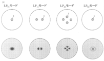
- the cavity 3 is arranged at the center in the fiber 10 for compensating the loss between modes, the cavity can be arranged at a desired position other than the center in order to give an arbitrary excess loss to an arbitrary mode. As shown in FIG. 2, by arranging the cavity 3 at a position where the electric field of each mode becomes strong, excess loss can be given to any mode.
- FIG. 3 is a diagram for explaining the entire fiber 10 for compensating for the loss between modes.
- the intermode loss difference compensating fiber 10 has a structure having one cavity 3 in a part of the longitudinal direction.
- calculate the connection loss calculate the electric field distribution propagating through the core structure having the cavity (first section) and the core structure not provided (second section) by the finite element method, and obtain the overlap of the electric field distributions. It is calculated by Note that the same calculation can be performed for an optical fiber in which a mode of 2LP mode or more propagates.
- the width of the cavity 3 (length in the longitudinal direction of the optical fiber) is about several ⁇ m.
- FIG. 4 is a diagram for explaining the relationship between the connection loss in the LP01 and LP11 modes and a2 / a1.
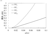
- a1 7 ⁇ m and ⁇ 1 are 0.4%. It can be confirmed that the loss increases as a2 / a1 increases, and that the loss received varies depending on the propagation mode.
- a2 / a1 needs to be 0.22 or less in order to make the excess loss other than the desired mode 0.1 dB or less.
- FIG. 5 is a diagram showing the value of a2 / a1 at which the allowable excess loss of the LP11 mode is 0.1 dB on the XY plane where a1 is the X axis and ⁇ 1 is the Y axis.
- the area (area above the broken line) is shown.
- 2LP mode transmission is possible in the C band (wavelength 1530 to 1565 nm) in a region between the two regions.
- the dashed line is a region where the effective area of the LP01 mode is 80 ⁇ m 2 or more (below the dashed line).
- the value of a2 / a1 at which the excess loss of the LP11 mode is 0.1 dB or less is shown, and the value of a2 / a1 means the maximum value of the size of the cavity 3.
- ⁇ 1 is desirably 0.65% or less. Therefore, in the range of 5.5 ⁇ m ⁇ a1 ⁇ 7.5 ⁇ m and 0.35% ⁇ 1 ⁇ 0.65%. , A2 / a1 ⁇ 0.235, the loss difference can be compensated while suppressing the loss in the LP11 mode.
- a radius a1 of the core portion and a relative refractive index difference ⁇ 1 are provided in a region surrounded by a polygon having a vertex as a vertex, and a radius a2 of the hollow portion satisfying a2 / a1 ⁇ 0.235 is set.
- a2 / a1 is 0.235 or less
- the excess loss given to the LP01 mode by the cavity 3 is limited. Therefore, as shown in FIG. 6, a plurality of cavities 3 having a2 / a1 (for example, 0.22 or less) having a small excess loss to the LP11 mode are arranged in the longitudinal direction of the optical fiber (that is, the first section and the first section). By repeating the second section a plurality of times), an arbitrary loss is given to the LP01 mode while suppressing excessive loss to the LP11 mode.
- the radius of the cavity 3 is reduced, and the number of the MDLs arranged in the longitudinal direction is adjusted.
- the degree of freedom in designing the compensation range is expanded.
- FIG. 8 is a diagram illustrating the structure of the inter-mode loss difference compensating fiber 20 of the present embodiment.
- the inter-mode loss difference compensating fiber 20 is an inter-mode loss difference compensating fiber that is inserted into an optical fiber whose propagation mode number is N (N is an integer of 2 or more), A cladding portion 5 and a core portion 1 having a radius a1 whose relative refractive index difference with respect to the cladding portion 5 is ⁇ 1, There are a first section and a second section in the light propagation direction, In the first section, a high refractive index of a ring shape having an inner ring diameter a2 and an outer ring diameter a3 (a2 ⁇ a3 ⁇ a1) in which the relative refractive index difference with respect to the cladding part 5 is ⁇ 2 in the area of the core part 1 in cross section.
- the head 7 is formed, In the second section, a ring-shaped high refractive index portion is not formed in a region of the core portion 1 in a cross section, It is characterized in that, among the propagation modes, a particular propagation mode has a larger loss than other propagation modes.
- FIG. 8A is a cross-sectional view of a first section of the fiber 20 for compensating for loss between modes.
- FIG. 8B shows the refractive index distribution in the radial direction of the first section of the inter-mode loss difference compensating fiber 20. It is assumed that the core radius is a1, the relative refractive index difference of the core portion 1 with respect to the cladding portion 5 is ⁇ 1, the inner ring diameter of the high refractive index portion 7 with the relative refractive index difference ⁇ 2 with respect to the cladding portion 5 is a2, and the outer ring diameter is a3.
- the electric field distribution of a specific mode propagating through the present fiber can be controlled, and the high refractive index portion and a region having no high refractive index portion can be controlled. It is possible to give a different loss for each propagation mode at the interface.
- the core shape of the mode loss difference compensating fiber 20 is obtained by spinning an optical fiber preform having a similar shape, and irradiating the optical fiber or the pure silica fine wire with a femtosecond laser under appropriate conditions as in the first embodiment. It can be realized by.
- FIG. 9 shows a region where the mode loss difference compensating fiber 20 can propagate the 4LP mode on the XY plane where the core diameter a1 is the X axis and the relative refractive index difference ⁇ 1 of the core is the Y axis.
- the area area above the broken line) is shown.
- the dashed line is a region where the effective area of the LP01 mode is 80 ⁇ m 2 or more (below the dashed line).
- the mode loss difference compensating fiber 20 is designed such that the radius a1 of the core portion 1 and the relative refractive index difference ⁇ 1 are located in a region surrounded by a polygon having a vertex.
- the loss of the mode for which excess loss is to be provided is higher than that of the other modes, and the loss difference between modes other than the mode for which excess loss is to be provided. It is important that the maximum value ⁇ L LPmn is small.
- LP mn indicates a mode in which excess loss is to be given.
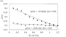
- FIG. 11 shows the maximum range of a2 / a1 at 6.0 ⁇ a1 ⁇ 8.0 and 0.6 ⁇ 1 ⁇ 1.1 from the range in which the 4LP mode described in FIG. 9 can propagate. From FIG.
- Equation 1 ⁇ 0.02 ( ⁇ 2 ⁇ 1) +0.22 ⁇ A2 / a1 ⁇ ⁇ 0.19 ( ⁇ 2 ⁇ 1) +0.41
- Equation 2 6.0 ⁇ a1 ⁇ 8.0 and 0.6 ⁇ 1 ⁇ 1.1.
- FIG. 12 and [Delta] L LP21 is 0.1dB or less, to maximize the loss difference between the LP 21 mode and the other modes are diagrams for explaining the relationship between a2 / a1 and Delta] 2-.DELTA.1.
- FIG. 12 also shows the maximum range of a2 / a1 at 6.0 ⁇ a1 ⁇ 8.0 and 0.6 ⁇ 1 ⁇ 1.1 from the range in which the 4LP mode described in FIG. 9 can propagate. From FIG. 12, it is possible to configure the mode loss difference compensating fiber 20 that can give an excess loss to the LP21 mode while suppressing ⁇ L LP21 to 0.1 dB or less in a region satisfying the following equation.
- Equation 2 X ⁇ a2 / a1 ⁇ 0.09 ( ⁇ 2 ⁇ 1) +0.56
- X is the following value.
- ⁇ 2 ⁇ 1 ⁇ 0.4 X ⁇ 0.04 ( ⁇ 2 ⁇ 1) +0.35
- X 0.35 ( ⁇ 2 ⁇ 1) +0.20
- 0.6 ⁇ 2 ⁇ 1 ⁇ 1.2 0.07 ( ⁇ 2 ⁇ 1) +0.36
- 6.0 ⁇ a1 ⁇ 8.0 and 0.6 ⁇ 1 ⁇ 1.1 6.0 ⁇ a1 ⁇ 8.0 and 0.6 ⁇ 1 ⁇ 1.1.
- the parameters (a1, a2, a3, ⁇ 1, ⁇ 2) of the mode loss difference compensating fiber 20 are assumed to have a small excess loss to the LPmn mode, and as shown in FIG.
- the degree of freedom in designing the MDL compensation range is increased.
- the structure in which the center of the optical fiber coincides with the center of the high refractive index portion 7 has been described.
- the present invention can be applied to a multi-core structure having a plurality of optical waveguides in a clad, and the high refractive index portion 7 can be formed for each core such that the center coincides with the center of the core.
- FIG. 13 is a diagram illustrating the mode loss difference compensator 30 of the present embodiment.
- the mode loss difference compensator 30 has a mode converter 25 that converts one of the other propagation modes and the specific mode at a stage preceding the mode loss difference compensating fiber (10 or 20).
- FIG. 14 is a diagram illustrating the relationship between the loss of the LP01, LP11, LP21, and LP02 modes in the mode loss compensating fiber 10 and a2.
- a mode switching unit 25 capable of mode conversion is arranged in front of the loss difference compensating fiber 10, and converts the LP01 mode to the LP02 mode and the LP02 mode to the LP01 mode. With the arrangement of the mode switching unit 25, it is possible to give a higher excess loss to the LP01 mode before the mode conversion than to the other modes.
- ⁇ LP02 can be suppressed to 0.1 dB or less while giving an excess loss of 0.12 dB to the LP02 mode as compared with other modes.
- the LP02 mode can be returned to the LP01 mode, and the LP01 mode can be returned to the LP02 mode, by inserting another mode switching unit after the loss difference compensating fiber 10.
- the mode converter 25 for the LP01 and LP02 modes can be realized by using, for example, a long-period fiber grating structure (for example, see Non-Patent Document 4).
- the mode converter 25 is not limited to the long-period grating, and can be replaced with a device having a mode conversion function described in Non-Patent Document 5.
- the mode conversion between LP01 and LP02 has been described, but the same effect can be obtained by selecting the mode to be converted according to LPmn of the loss difference compensating fiber.
- FIG. 15 is a diagram illustrating a multimode optical amplifier (41, 42) having a loss difference compensating fiber.
- the optical amplifiers (41, 42) An amplification optical fiber 43 for amplifying signal light propagating through an optical fiber whose propagation mode number is N (N is an integer of 2 or more); An excitation light source 44 for transmitting excitation light for exciting the amplification optical fiber 43; At least one loss compensation fiber (10, 20) to which the signal light passed through the amplification fiber 43 is input; Is provided.
- a gain difference occurs between the modes depending on the rare earth distribution of the amplification fiber and the conditions of the pump light (for example, see Non-Patent Documents 6 and 7). It is necessary to provide a loss for compensating the gain difference between modes.
- the loss difference compensating fiber 20 that gives a high excess loss to the LP11 mode described in the first and second embodiments the loss difference compensating fiber 20 that gives a high excess loss to the LP21 mode, and the loss difference that gives a high excess loss to the LP02 mode
- the inter-mode gain difference is compensated by combining the compensating fiber 10 and the mode converter 25 of LP01 and LP02 described in the third embodiment.
- the optical amplifier 47 By designing a characteristic having an anti-correlation with the gain characteristic of the optical amplifier 47, it is possible to reduce the gain difference between modes in the 4LP mode optical amplifier. If the excess loss characteristics of the loss difference compensating fiber are inversely correlated with the gain characteristics of the optical amplifier 47, only the loss difference compensating fiber may be connected to the subsequent stage of the optical amplifier 47 (FIG. 15A). ) Optical amplifier 41). However, if the excess loss characteristic of the single loss difference compensating fiber is not the characteristic of the anti-correlation with the gain characteristic of the optical amplifier 47, a plurality of loss difference compensating fibers and a mode converter are combined, and the total of the optical amplifier is combined. A gain characteristic of 47 and an anti-correlation characteristic are created (the optical amplifier 42 in FIG. 15B).
- FIG. 16 is a flowchart illustrating the present transmission path design method.
- the transmission line design method includes: a gain acquisition step S01 for acquiring a gain of each propagation mode of an optical amplifying unit that amplifies signal light propagating through an optical fiber whose number of propagation modes is N (N is an integer of 2 or more); A gain difference calculating step S02 for calculating a gain difference ⁇ G LPmn (mn is a mode number) between the propagation mode having the minimum gain and the other propagation modes among the gains obtained in the gain obtaining procedure;
- the loss compensator i giving excessive loss to one of the other propagation modes (i is N-1 or less natural number) was prepared n i stand respectively for each loss compensator i each propagation mode (LPmn)
- Loss compensator characteristic acquisition procedure S03 for acquiring the loss ⁇ i_LPmn given to For each of the propagation modes, calculate the sum of the gain of the optical amplifier and the loss given by all the loss compensators i ( ⁇ DMG
- Gain acquisition procedure S01 First, the value of the gain of each propagation mode generated in an optical amplifier (for example, an optical fiber for amplification) is obtained.
- the gain may be measured or obtained from the specifications of the optical amplifier.
- Gain difference calculation procedure S02 When there are two propagation modes, a gain difference between the propagation modes is calculated. If the number of propagation modes is three or more, the gain difference between the gain of each propagation mode and the mode with the smallest gain is calculated.
- the loss values shown in the first to third embodiments are obtained from the overlap integral of the field distribution, and are the loss values at one connection point.
- the compensator is connected by a fiber, a mode mismatch occurs at two points of the input part and the output part. Therefore, a doubled loss value is used below.
- Non-Patent Document 7 An example in which the gain at a wavelength of 1546 nm is compensated from the gain spectrum described in Non-Patent Document 7 will be described.
Landscapes
- Physics & Mathematics (AREA)
- Optics & Photonics (AREA)
- Engineering & Computer Science (AREA)
- General Physics & Mathematics (AREA)
- Electromagnetism (AREA)
- Computer Networks & Wireless Communication (AREA)
- Signal Processing (AREA)
- Plasma & Fusion (AREA)
- Lasers (AREA)
- Optical Fibers, Optical Fiber Cores, And Optical Fiber Bundles (AREA)
- Optical Communication System (AREA)
Abstract
簡易な構造で精密なアライメント作業を不要としながら、MDLを低減できるモード間損失差補償用ファイバ、光増幅器、および伝送路設計方法を提供することを目的とする。 本発明に係るモード間損失差補償用ファイバは、光ファイバのコアに空洞部もしくはリング状の高屈折率部を形成することで所望の伝搬モードに過剰損失を与えることとした。コアのプロファイルの一部に空洞もしくはリング状の高屈折率部を付与することによって本ファイバを伝搬する特定のモードの電界分布を制御することができ、空洞部もしくはリング状の高屈折率部とこれを有しない領域との界面で伝搬モード毎に異なる損失を与えることが可能となる。
Description
本開示は、伝送路を伝搬する信号光のモード間利得差を補償するモード間損失差補償用ファイバ、光増幅器、および伝送路設計方法に関する。
近年、サービスの多様化によりインターネットトラヒックは未だ増加し続けており、伝送速度の高速化や波長分割多重(Wavelength Division Multiplexing:WDM)技術による波長多重数の増加により飛躍的に伝送容量を伸ばしてきた。また近年、検討が盛んに行われているデジタルコヒーレント技術によって更なる伝送容量の拡大が予想されている。デジタルコヒーレント伝送システムでは多値位相変調信号を用いることにより周波数利用効率を向上させてきたが、より高い信号雑音比が必要となってくる。しかし従来のシングルモードファイバ(Single mode fiber、 SMF)を用いた伝送システムでは、理論的な限界に加え非線形効果に起因する入力パワー制限のため伝送容量は100 Tbit/secを境に飽和することが予想されており、更なる大容量化は困難となってきている。
今後さらに伝送容量を増やしていくためには革新的な伝送容量拡大を実現する媒体が必要とされている。そこで、光ファイバ中の複数の伝搬モードをチャネルとして用いることで信号雑音比と空間利用効率の向上が期待できるマルチモードファイバ(Multi mode fiber、 MMF)を用いたモード多重伝送が注目を集めている。これまでファイバ中を伝搬する高次のモードは信号劣化の要因であったが、デジタル信号処理や合分波技術などの発展で積極的な利用が検討されている(例えば、非特許文献1、2を参照。)。
伝送容量の拡大に加えモード多重伝送の長距離化に向けた検討も行われており、3モード伝搬可能な非結合型の12コアファイバを用いた527km伝送の報告がなされている(例えば、非特許文献3を参照。)。
N.Hanzawa et al., "Demonstration of Mode-Division multiplexing Transmission Over 10 km Two-mode Fiber with Mode Coupler" OFC2011, paper OWA4
T.Sakamoto et al., "Modal Dispersion Technique for Long-haul Transmission over Few-mode Fiber with SIMO Configuration" ECOC2011, We.10.P1.82
K. Shibahara et al. "Dense SDM (12-Core × 3-Mode) Transmission Over 527 km With 33.2-ns Mode-Dispersion Employing Low-Complexity Parallel MIMO Frequency-Domain Equalization," J. Lightw. Technol., vol.34, no. 1 (2016).
X. Zhao et al. "Mode converter based on the long-period fiber gratings written in the six-mode fiber," ICOCN, 2017.
T. Fujisawa et al.,"One chip,PLC three-mode exchanger based on symmetric and asymmetric directional couplers with integrated mode rotator," OFC 2017,Paper.W1b.2.
M. Salsi et al.,"A Six-mode erbium-doped fiber amplifier,"ECOC 2012,Paper. Th.3.A.6.
Y. Jung et al.,"Reconfigurable modal gain control of a few-mode EDFA supporting six spatial modes," IEEE Photonics Technology Letters, vol.26,No.11,June (2014)
モード多重伝送の長距離化を行う上で、長距離伝送を行うためには伝送路にて発生するモード間損失差(Differential modal attenuation:DMA)や光増幅器にて発生するモード間利得差(Differential modal gain:DMG)が重要となってくる。非特許文献3においても長距離伝送を実現するためにDMA及びDMGを含めたモード間損失差(Mode dependent loss:MDL)を1スパンの中で0.2dB以下になるように調整を行っている。非特許文献3においては空間フィルタ型のモード間損失差補償器を用いてLP01モードにLP11モードに比べ3dB程度大きい損失を与えることでMDLの低減に寄与している。
しかし、非特許文献3のような空間型の利得等化器は、ファイバ以外に、レンズや特定のモードに損失を与えるためのフィルタ等を用いるため、構造が複雑である、及び伝搬モード間のクロストーク抑制するために精密なアライメント作業が必要であるという課題があった。
そこで、本発明は、上記課題を解決するために、簡易な構造で精密なアライメント作業を不要としながら、MDLを低減できるモード間損失差補償用ファイバ、光増幅器、および伝送路設計方法を提供することを目的とする。
上記目的を達成するために、本発明に係るモード間損失差補償用ファイバは、光ファイバのコアに空洞部もしくはリング状の高屈折率部を形成することで所望の伝搬モードに過剰損失を与えることとした。
本発明に係るモード間損失差補償用ファイバは、伝搬モード数がN(Nは2以上の整数)である光ファイバに挿入されるモード間損失差補償用ファイバであって、
クラッド部、及び前記クラッド部に対する比屈折率差がΔ1である半径a1のコア部で構成され、
光の伝搬方向に第1区間と第2区間があり、
前記第1区間では、断面において前記コア部の領域の一部に半径a2(a2<a1)の空洞部が形成され、
前記第2区間では、断面において前記コア部の領域には空洞部が形成されておらず、
前記伝搬モードの内、特定の伝搬モードに他の伝搬モードより大きい損失を与えることを特徴とする。
本モード間損失差補償用ファイバは、空間光学素子を用いないため、構造が簡易である。従って、本発明は、簡易な構造で精密なアライメント作業を不要としながら、MDLを低減できるモード間損失差補償用ファイバを提供することができる。
クラッド部、及び前記クラッド部に対する比屈折率差がΔ1である半径a1のコア部で構成され、
光の伝搬方向に第1区間と第2区間があり、
前記第1区間では、断面において前記コア部の領域の一部に半径a2(a2<a1)の空洞部が形成され、
前記第2区間では、断面において前記コア部の領域には空洞部が形成されておらず、
前記伝搬モードの内、特定の伝搬モードに他の伝搬モードより大きい損失を与えることを特徴とする。
本モード間損失差補償用ファイバは、空間光学素子を用いないため、構造が簡易である。従って、本発明は、簡易な構造で精密なアライメント作業を不要としながら、MDLを低減できるモード間損失差補償用ファイバを提供することができる。
このモード間損失差補償用ファイバの具体的なパラメータとしては、前記コア部の半径a1をX軸、比屈折率差Δ1をY軸としたXY平面において、
A1(5.6,0.65)
B1(5.4,0.55)
C1(5.33,0.53)
D1(5.5,0.51)
E1(6.0,0.45)
F1(6.5,0.41)
G1(7.0,0.38)
H1(7.55,0.36)
I1(7.0,0.42)
J1(6.5,0.48)
K1(6.0,0.575)
を頂点とする多角形で囲まれる領域に前記コア部の半径a1及び比屈折率差Δ1があり、且つa2/a1<0.235を満たす前記空洞部の半径a2が設定されていることを特徴とする。
このモード間損失差補償用ファイバは、C帯の波長(1530~1565nm)においてLP01モードとLP11モードを伝送することができ、LP11モードの損失を抑えつつ、LP01モードに大きな損失を与えることができる。
A1(5.6,0.65)
B1(5.4,0.55)
C1(5.33,0.53)
D1(5.5,0.51)
E1(6.0,0.45)
F1(6.5,0.41)
G1(7.0,0.38)
H1(7.55,0.36)
I1(7.0,0.42)
J1(6.5,0.48)
K1(6.0,0.575)
を頂点とする多角形で囲まれる領域に前記コア部の半径a1及び比屈折率差Δ1があり、且つa2/a1<0.235を満たす前記空洞部の半径a2が設定されていることを特徴とする。
このモード間損失差補償用ファイバは、C帯の波長(1530~1565nm)においてLP01モードとLP11モードを伝送することができ、LP11モードの損失を抑えつつ、LP01モードに大きな損失を与えることができる。
また、本発明に係る他のモード間損失差補償用ファイバは、伝搬モード数がN(Nは2以上の整数)である光ファイバに挿入されるモード間損失差補償用ファイバであって、
クラッド部、及び前記クラッド部に対する比屈折率差がΔ1である半径a1のコア部で構成され、
光の伝搬方向に第1区間と第2区間があり、
前記第1区間では、断面において前記コア部の領域に、前記クラッド部に対する比屈折率差がΔ2である、内環径a2且つ外環径a3(a2<a3<a1)のリング形状の高屈折率部が形成され、
前記第2区間では、断面において前記コア部の領域にはリング形状の高屈折率部が形成されず、
前記伝搬モードの内、特定の伝搬モードに他の伝搬モードより大きい損失を与えることを特徴とする。
本モード間損失差補償用ファイバも、空間光学素子を用いないため、構造が簡易である。従って、本発明は、簡易な構造で精密なアライメント作業を不要としながら、MDLを低減できるモード間損失差補償用ファイバを提供することができる。
クラッド部、及び前記クラッド部に対する比屈折率差がΔ1である半径a1のコア部で構成され、
光の伝搬方向に第1区間と第2区間があり、
前記第1区間では、断面において前記コア部の領域に、前記クラッド部に対する比屈折率差がΔ2である、内環径a2且つ外環径a3(a2<a3<a1)のリング形状の高屈折率部が形成され、
前記第2区間では、断面において前記コア部の領域にはリング形状の高屈折率部が形成されず、
前記伝搬モードの内、特定の伝搬モードに他の伝搬モードより大きい損失を与えることを特徴とする。
本モード間損失差補償用ファイバも、空間光学素子を用いないため、構造が簡易である。従って、本発明は、簡易な構造で精密なアライメント作業を不要としながら、MDLを低減できるモード間損失差補償用ファイバを提供することができる。
このモード間損失差補償用ファイバの具体的なパラメータとしては、前記コア部の半径a1をX軸、比屈折率差Δ1をY軸としたXY平面において、
A2(6.0,1.02)
B2(5.9,0.95)
C2(6.5,0.80)
D2(7.0,0.71)
E2(7.75,0.61)
F2(7.0,0.75)
G2(6.5,0.88)
を頂点とする多角形で囲まれる領域に前記コア部の半径a1及び比屈折率差Δ1があり、且つ
-0.02(Δ2―Δ1)+0.22<a2/a1<-0.19(Δ2―Δ1)+0.41
を満たす前記リング形状の高屈折率部の半径a2及び比屈折率差Δ2が設定されていることを特徴とする。
このモード間損失差補償用ファイバは、C帯の波長(1530~1565nm)においてLP01モード、LP11モード、LP21モード、及びLP02モードを伝送することができ、LP01モード、LP21モード、及びLP02モードの損失を抑えつつ、LP11モードに大きな損失を与えることができる。
A2(6.0,1.02)
B2(5.9,0.95)
C2(6.5,0.80)
D2(7.0,0.71)
E2(7.75,0.61)
F2(7.0,0.75)
G2(6.5,0.88)
を頂点とする多角形で囲まれる領域に前記コア部の半径a1及び比屈折率差Δ1があり、且つ
-0.02(Δ2―Δ1)+0.22<a2/a1<-0.19(Δ2―Δ1)+0.41
を満たす前記リング形状の高屈折率部の半径a2及び比屈折率差Δ2が設定されていることを特徴とする。
このモード間損失差補償用ファイバは、C帯の波長(1530~1565nm)においてLP01モード、LP11モード、LP21モード、及びLP02モードを伝送することができ、LP01モード、LP21モード、及びLP02モードの損失を抑えつつ、LP11モードに大きな損失を与えることができる。
このモード間損失差補償用ファイバの具体的な他のパラメータとしては、前記コア部の半径a1をX軸、比屈折率差Δ1をY軸としたXY平面において、
A2(6.0,1.02)
B2(5.9,0.95)
C2(6.5,0.80)
D2(7.0,0.71)
E2(7.75,0.61)
F2(7.0,0.75)
G2(6.5,0.88)
を頂点とする多角形で囲まれる領域に前記コア部の半径a1及び比屈折率差Δ1があり、且つ
X <a2/a1<-0.09(Δ2―Δ1)+0.56
を満たす前記リング形状の高屈折率部の半径a2及び比屈折率差Δ2が設定されていることを特徴とする。
ただし、Xは
Δ2―Δ1<0.4のとき、X=-0.04(Δ2―Δ1)+0.35
0.4<Δ2―Δ1<0.6のとき、X=0.35(Δ2―Δ1)+0.20
0.6<Δ2―Δ1<1.2のとき、X=0.07(Δ2―Δ1)+0.36
である。
このモード間損失差補償用ファイバは、C帯の波長(1530~1565nm)においてLP01モード、LP11モード、LP21モード、及びLP02モードを伝送することができ、LP01モード、LP11モード、及びLP02モードの損失を抑えつつ、LP21モードに大きな損失を与えることができる。
A2(6.0,1.02)
B2(5.9,0.95)
C2(6.5,0.80)
D2(7.0,0.71)
E2(7.75,0.61)
F2(7.0,0.75)
G2(6.5,0.88)
を頂点とする多角形で囲まれる領域に前記コア部の半径a1及び比屈折率差Δ1があり、且つ
X <a2/a1<-0.09(Δ2―Δ1)+0.56
を満たす前記リング形状の高屈折率部の半径a2及び比屈折率差Δ2が設定されていることを特徴とする。
ただし、Xは
Δ2―Δ1<0.4のとき、X=-0.04(Δ2―Δ1)+0.35
0.4<Δ2―Δ1<0.6のとき、X=0.35(Δ2―Δ1)+0.20
0.6<Δ2―Δ1<1.2のとき、X=0.07(Δ2―Δ1)+0.36
である。
このモード間損失差補償用ファイバは、C帯の波長(1530~1565nm)においてLP01モード、LP11モード、LP21モード、及びLP02モードを伝送することができ、LP01モード、LP11モード、及びLP02モードの損失を抑えつつ、LP21モードに大きな損失を与えることができる。
本発明に係るモード間損失差補償用ファイバは、さらに、前記第1区間の前段に前記他の伝搬モードのひとつと前記特定のモードとを変換するモード変換部を有することを特徴とする。構造的に所望の伝搬モードに過剰損失を与えることができないとき、前段において所望の伝搬モードから過剰損失を与えることができる伝搬モードへ変換を行うことで所望の伝搬モードに過剰損失を与えることができる。
本発明に係る光増幅器は、
伝搬モード数がN(Nは2以上の整数)である光ファイバを伝搬する信号光を増幅する増幅用光ファイバと、
前記増幅用光ファイバを励起する励起光を送信する励起光源と、
前記増幅用ファイバを通過した信号光が入力される、少なくとも1つの請求項1から6のいずれかに記載の損失差補償用ファイバと、
を備える。
本光増幅器は、前記モード間損失差補償用ファイバを備えるため、モード間利得差を小さくすることができる。
伝搬モード数がN(Nは2以上の整数)である光ファイバを伝搬する信号光を増幅する増幅用光ファイバと、
前記増幅用光ファイバを励起する励起光を送信する励起光源と、
前記増幅用ファイバを通過した信号光が入力される、少なくとも1つの請求項1から6のいずれかに記載の損失差補償用ファイバと、
を備える。
本光増幅器は、前記モード間損失差補償用ファイバを備えるため、モード間利得差を小さくすることができる。
本発明に係る伝送路設計方法は、
伝搬モード数がN(Nは2以上の整数)である光ファイバを伝搬する信号光を増幅する光増幅器の各伝搬モードの利得を取得する利得取得手順と、
前記利得取得手順で取得した利得のうち最小利得の伝搬モードと他の伝搬モードとの利得差ΔGLPmn(mnはモード番号)を算出する利得差算出手順と、
前記他の伝搬モードのうちのひとつに対して過剰損失を与える損失補償器i(iはN-1以下の自然数)をそれぞれni台用意し、損失補償器i毎に各伝搬モード(LPmn)に与える損失αi_LPmnを取得する損失補償器特性取得手順と、
前記伝搬モード毎に、前記光増幅器の利得と全ての前記損失補償器iで与えられる損失の合計(ΔDMGLPmn)を算出し、
(a)いずれのΔDMGLPmnも10dB以下、且つ
(b)ΔDMGLPmnの最大値と最小値の差MDLが最小
となる、それぞれの前記損失補償器iの数niを見出す探索手順と、
を行う。
本伝送路設計方法は、MDLを低減した伝送路を設計することができる。
伝搬モード数がN(Nは2以上の整数)である光ファイバを伝搬する信号光を増幅する光増幅器の各伝搬モードの利得を取得する利得取得手順と、
前記利得取得手順で取得した利得のうち最小利得の伝搬モードと他の伝搬モードとの利得差ΔGLPmn(mnはモード番号)を算出する利得差算出手順と、
前記他の伝搬モードのうちのひとつに対して過剰損失を与える損失補償器i(iはN-1以下の自然数)をそれぞれni台用意し、損失補償器i毎に各伝搬モード(LPmn)に与える損失αi_LPmnを取得する損失補償器特性取得手順と、
前記伝搬モード毎に、前記光増幅器の利得と全ての前記損失補償器iで与えられる損失の合計(ΔDMGLPmn)を算出し、
(a)いずれのΔDMGLPmnも10dB以下、且つ
(b)ΔDMGLPmnの最大値と最小値の差MDLが最小
となる、それぞれの前記損失補償器iの数niを見出す探索手順と、
を行う。
本伝送路設計方法は、MDLを低減した伝送路を設計することができる。
本発明は、簡易な構造で精密なアライメント作業を不要としながら、MDLを低減できるモード間損失差補償用ファイバ、光増幅器、および伝送路設計方法を提供することができる。
添付の図面を参照して本発明の実施形態を説明する。以下に説明する実施形態は本発明の実施例であり、本発明は、以下の実施形態に制限されるものではない。なお、本明細書及び図面において符号が同じ構成要素は、相互に同一のものを示すものとする。
(実施形態1)
図1は、本実施形態のモード間損失差補償用ファイバ10の構造を説明する図である。モード間損失差補償用ファイバ10は、伝搬モード数がN(Nは2以上の整数)である光ファイバに挿入されるモード間損失差補償用ファイバであって、
クラッド部5、及びクラッド部5に対する比屈折率差がΔ1である半径a1のコア部1で構成され、
光の伝搬方向に第1区間と第2区間があり、
前記第1区間では、断面においてコア部1の領域の一部に半径a2(a2<a1)の空洞部3が形成され、
前記第2区間では、断面においてコア部1の領域には空洞部が形成されておらず、
前記伝搬モードの内、特定の伝搬モードに他の伝搬モードより大きい損失を与えることを特徴とする。
図1は、本実施形態のモード間損失差補償用ファイバ10の構造を説明する図である。モード間損失差補償用ファイバ10は、伝搬モード数がN(Nは2以上の整数)である光ファイバに挿入されるモード間損失差補償用ファイバであって、
クラッド部5、及びクラッド部5に対する比屈折率差がΔ1である半径a1のコア部1で構成され、
光の伝搬方向に第1区間と第2区間があり、
前記第1区間では、断面においてコア部1の領域の一部に半径a2(a2<a1)の空洞部3が形成され、
前記第2区間では、断面においてコア部1の領域には空洞部が形成されておらず、
前記伝搬モードの内、特定の伝搬モードに他の伝搬モードより大きい損失を与えることを特徴とする。
図1(A)は、モード間損失差補償用ファイバ10の第1区間の断面図である。図1(B)は、モード間損失差補償用ファイバ10の第1区間の半径方向における屈折率分布を示したものである。コア半径をa1、クラッド部5に対するコア部1の比屈折率差をΔ1とする。本実施形態ではステップ形状および円筒状の光ファイバとしたときの例を示すが、効果については他の屈折率形状、および導波路構造についても同様に考えることができる。
一般的にマルチモード光ファイバにおいては、高次モードに比べ基本モードは閉じ込めが強くなり曲げ損失を含む伝搬損失が小さくなる傾向がある。そこでモード多重伝送システムでMDLを小さくするためには基本モードに対して高次モードより大きな過剰損失を与えられる構造を考える必要がある。本実施形態ではコア1の中心に空洞部3を有する例を示す。
空洞部3は、コア部1の内半径a2(0≦a2≦a1)の領域とする。このようにコアプロファイルの一部に空洞を付与することによって本ファイバを伝搬する特定のモードの電界分布を制御することができ、空洞部とこれを有しない領域との界面で伝搬モード毎に異なる損失を与えることが可能となる。
光ファイバに空洞を付与する方法としては、フェムト秒レーザを光導波路に照射する手法が知られており、照射条件を制御することによって屈折率変化や空洞部領域の作製を行うことができる。なお、モード間損失差補償用ファイバ10では空洞部3を中心に配置したが、任意のモードに対し任意の過剰損失を与えるため、空洞部は中心以外に所望の位置に配置できる。図2に示すように、各モードの電界が強くなる位置に空洞部3を配置することで任意のモードに対し過剰損失を与えることができる。
以下、2LPモード伝搬可能な光ファイバにおけるa2と伝搬損失の関係について説明する。
図3は、モード間損失差補償用ファイバ10の全体を説明する図である。モード間損失差補償用ファイバ10は長手方向の一部に空洞部3を1箇所有する構造である。接続損失の計算には、空洞部を有するコア構造(第1区間)と付与していないコア構造(第2区間)を伝搬する電界分布を有限要素法により計算し、電界分布の重なりを求めることで算出している。なお、2LPモード以上のモードが伝搬する光ファイバにおいても同様に計算することが可能である。なお、空洞部3の幅(光ファイバ長手方向の長さ)は数μm程度である。
図3は、モード間損失差補償用ファイバ10の全体を説明する図である。モード間損失差補償用ファイバ10は長手方向の一部に空洞部3を1箇所有する構造である。接続損失の計算には、空洞部を有するコア構造(第1区間)と付与していないコア構造(第2区間)を伝搬する電界分布を有限要素法により計算し、電界分布の重なりを求めることで算出している。なお、2LPモード以上のモードが伝搬する光ファイバにおいても同様に計算することが可能である。なお、空洞部3の幅(光ファイバ長手方向の長さ)は数μm程度である。
図4は、LP01及びLP11モードの接続損失とa2/a1との関係を説明する図である。ここでa1=7μmおよびΔ1は0.4%としている。a2/a1の増大に伴い損失が増大すること、及び伝搬モードによって受ける損失が異なることが確認できる。モード間損失差補償用ファイバの特性として所望のモード(ここではLP01モード)以外の過剰損失をできるだけ小さくすることが求められる。所望のモード以外の過剰損失を0.1dB以下とするためには、図4よりa2/a1を0.22以下とする必要があることがわかる。
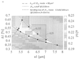
図5は、a1をX軸、Δ1をY軸としたXY平面において、許容されるLP11モードの過剰損失が0.1dBとなるa2/a1の値を示した図である。図5において、点線は波長1530nmにおけるLP21モードの理論カットオフ(点線より下の領域はLP21が伝搬しない)、破線は波長1565nm,R=30mmにおけるLP11モードの曲げ損失が0.5dB/100turnとなる領域(破線より上の領域)を示している。両領域に挟まれる領域においてC帯(波長1530~1565nm)で2LPモード伝送が可能となる。なお、一点鎖線は、LP01モードの実効断面積が80μm2以上となる領域(一点鎖線より下側)である。
図5のXY平面においてLP11モードの過剰損失が0.1dB以下となるa2/a1の値を示しており、そのa2/a1の値は空洞部3の大きさの最大値を意味する。LP01モードの実効断面積が80μm2以上とするとΔ1は0.65%以下であることが望ましいため、5.5μm<a1<7.5μm、0.35%<Δ1<0.65%の範囲において、a2/a1<0.235、とすることでLP11モードの損失を抑えながら損失差を補償することができる。
より正確には、前記コア部の半径a1をX軸、比屈折率差Δ1をY軸としたXY平面において、
A1(5.6,0.65)
B1(5.4,0.55)
C1(5.33,0.53)
D1(5.5,0.51)
E1(6.0,0.45)
F1(6.5,0.41)
G1(7.0,0.38)
H1(7.55,0.36)
I1(7.0,0.42)
J1(6.5,0.48)
K1(6.0,0.575)
を頂点とする多角形で囲まれる領域に前記コア部の半径a1及び比屈折率差Δ1があり、且つa2/a1<0.235を満たす前記空洞部の半径a2が設定されている。
より正確には、前記コア部の半径a1をX軸、比屈折率差Δ1をY軸としたXY平面において、
A1(5.6,0.65)
B1(5.4,0.55)
C1(5.33,0.53)
D1(5.5,0.51)
E1(6.0,0.45)
F1(6.5,0.41)
G1(7.0,0.38)
H1(7.55,0.36)
I1(7.0,0.42)
J1(6.5,0.48)
K1(6.0,0.575)
を頂点とする多角形で囲まれる領域に前記コア部の半径a1及び比屈折率差Δ1があり、且つa2/a1<0.235を満たす前記空洞部の半径a2が設定されている。
しかしながらa2/a1が0.235以下の領域では、空洞部3がLP01モードに与える過剰損失に制限が生じてしまう。そこで図6に示すようにLP11モードへの過剰損失の小さいa2/a1(例えば、0.22以下)を有する空洞部3を光ファイバの長手方向に複数個並べる(すなわち、前記第1区間と前記第2区間とを複数回繰り返す)ことでLP11モードへの過剰損失を抑えながらLP01モードへ任意の損失を与える。
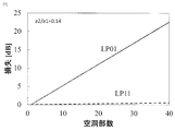
図7は、a2/a1=0.14であるときの空洞部3の数と各モードの損失の関係を説明する図である。図7より、空洞部3の数を増加させることでLP11モードへの損失を0.6dB以下に抑えながらLP01モードへ20dB以上の損失を与えられることがわかる。
以上より、図5で示したモード間損失差補償用ファイバ10と空洞部3の半径との関係において、空洞部3の半径を小さくし、長手方向に配置する個数を調整することで、MDLの補償範囲の設計の自由度が広がる。
(実施形態2)
図8は、本実施形態のモード間損失差補償用ファイバ20の構造を説明する図である。モード間損失差補償用ファイバ20は、伝搬モード数がN(Nは2以上の整数)である光ファイバに挿入されるモード間損失差補償用ファイバであって、
クラッド部5、及びクラッド部5に対する比屈折率差がΔ1である半径a1のコア部1で構成され、
光の伝搬方向に第1区間と第2区間があり、
前記第1区間では、断面においてコア部1の領域に、クラッド部5に対する比屈折率差がΔ2である、内環径a2且つ外環径a3(a2<a3<a1)のリング形状の高屈折率部7が形成され、
前記第2区間では、断面においてコア部1の領域にはリング形状の高屈折率部が形成されず、
前記伝搬モードの内、特定の伝搬モードに他の伝搬モードより大きい損失を与えることを特徴とする。
図8は、本実施形態のモード間損失差補償用ファイバ20の構造を説明する図である。モード間損失差補償用ファイバ20は、伝搬モード数がN(Nは2以上の整数)である光ファイバに挿入されるモード間損失差補償用ファイバであって、
クラッド部5、及びクラッド部5に対する比屈折率差がΔ1である半径a1のコア部1で構成され、
光の伝搬方向に第1区間と第2区間があり、
前記第1区間では、断面においてコア部1の領域に、クラッド部5に対する比屈折率差がΔ2である、内環径a2且つ外環径a3(a2<a3<a1)のリング形状の高屈折率部7が形成され、
前記第2区間では、断面においてコア部1の領域にはリング形状の高屈折率部が形成されず、
前記伝搬モードの内、特定の伝搬モードに他の伝搬モードより大きい損失を与えることを特徴とする。
図8(A)は、モード間損失差補償用ファイバ20の第1区間の断面図である。図8(B)は、モード間損失差補償用ファイバ20の第1区間の半径方向における屈折率分布を示したものである。コア半径をa1、クラッド部5に対するコア部1の比屈折率差をΔ1、クラッド部5に対する比屈折率差Δ2の高屈折率部7の内環径をa2、外環径をa3とする。このようにコアプロファイルの一部にリング状の高屈折率部を付与することによって本ファイバを伝搬する特定のモードの電界分布を制御することができ、高屈折率部とこれを有しない領域との界面で伝搬モード毎に異なる損失を与えることが可能となる。
モード損失差補償用ファイバ20のコア形状は相似形の光ファイバ母材を紡糸して得られるほか、実施形態1と同様に適切な条件でフェムト秒レーザを光ファイバもしくは純石英細線に照射することによって実現することができる。
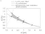
図9は、コア径a1をX軸、コアの比屈折率差Δ1をY軸としたXY平面において、モード損失差補償用ファイバ20が4LPモードを伝搬可能な領域を示す。図9において、点線は波長1530nmにおけるLP31モードの理論カットオフ(点線より下の領域はLP31が伝搬しない)、破線は波長1565nm,R=30mmにおけるLP02モードの曲げ損失が0.5dB/100turnとなる領域(破線より上の領域)を示している。両領域に挟まれる領域においてC帯(波長1530~1565nm)で4LPモード伝送が可能となる。なお、一点鎖線は、LP01モードの実効断面積が80μm2以上となる領域(一点鎖線より下側)である。
4LPモード伝送が可能となる範囲をより正確に記載すると、
コア部1の半径a1をX軸、比屈折率差Δ1をY軸としたXY平面において、
A2(6.0,1.02)
B2(5.9,0.95)
C2(6.5,0.80)
D2(7.0,0.71)
E2(7.75,0.61)
F2(7.0,0.75)
G2(6.5,0.88)
を頂点とする多角形で囲まれる領域にコア部1の半径a1及び比屈折率差Δ1があるようにモード損失差補償用ファイバ20を設計する。
コア部1の半径a1をX軸、比屈折率差Δ1をY軸としたXY平面において、
A2(6.0,1.02)
B2(5.9,0.95)
C2(6.5,0.80)
D2(7.0,0.71)
E2(7.75,0.61)
F2(7.0,0.75)
G2(6.5,0.88)
を頂点とする多角形で囲まれる領域にコア部1の半径a1及び比屈折率差Δ1があるようにモード損失差補償用ファイバ20を設計する。
図10は、モード損失差補償用ファイバ20の構造をa1=7.2μm、a2-a3=2μm、Δ1=0.7%、Δ2=1.2%としたときの各モードの損失とa2/a1の関係を説明する図である。a2/a1の変化に伴い各モードの損失が正弦波状に変動していることが確認できる。モード損失差補償用ファイバ20をモード補償器として利用するためには、過剰損失を与えたいモードの損失が他のモードと比べて高いこと、及び過剰損失を与えたいモード以外のモード間損失差の最大値ΔLLPmnが小さいことが重要である。ここでLPmnは過剰損失を与えたいモードを示す。図6に示すように、長手方向に高屈折率部7を複数個並べる(すなわち、前記第1区間と前記第2区間とを複数回繰り返す)ことを想定すると、ΔLLPmnは0.1dB以下に抑えることが望ましい。図10より、例えば、a2/a1=0.27とすればΔLLP11を0.1dB以下に抑えつつ、LP11モードと他のモードとの損失差を最大とすることができる。また、a2/a1=0.46とすればΔLLP21を0.1dB以下に抑えつつ、LP21モードの損失と他のモードとの損失差を最大とすることができる。
モード損失差補償用ファイバ20の構造a1、Δ1及びΔ2を変化させても同様の効果が得られることを説明する。図11は、ΔLLP11が0.1dB以下かつ、LP11モードと他のモードとの損失差を最大とする、a2/a1とΔ2-Δ1との関係を説明する図である。図11では、図9で説明した4LPモードが伝搬可能である範囲より、6.0<a1<8.0、0.6<Δ1<1.1でa2/a1の最大範囲を示している。図11より、次式を満たす領域でΔLLP11を0.1dB以下に抑えつつ、LP11モードに過剰損失を与えることができるモード損失差補償用ファイバ20を構成できる。
(式1)
-0.02(Δ2―Δ1)+0.22
<a2/a1<
-0.19(Δ2―Δ1)+0.41
ただし、6.0<a1<8.0、0.6<Δ1<1.1である。
(式1)
-0.02(Δ2―Δ1)+0.22
<a2/a1<
-0.19(Δ2―Δ1)+0.41
ただし、6.0<a1<8.0、0.6<Δ1<1.1である。
同様に、図12は、ΔLLP21が0.1dB以下かつ、LP21モードと他のモードとの損失差を最大とする、a2/a1とΔ2-Δ1との関係を説明する図である。図12でも、図9で説明した4LPモードが伝搬可能である範囲より、6.0<a1<8.0、0.6<Δ1<1.1でa2/a1の最大範囲を示している。図12より、次式を満たす領域でΔLLP21を0.1dB以下に抑えつつ、LP21モードに過剰損失を与えることができるモード損失差補償用ファイバ20を構成できる。
(式2)
X <a2/a1 <-0.09(Δ2―Δ1)+0.56
ここで、Xは以下の値である。
Δ2―Δ1<0.4のとき X=-0.04(Δ2―Δ1)+0.35
0.4<Δ2―Δ1<0.6のとき X=0.35(Δ2―Δ1)+0.20
0.6<Δ2―Δ1<1.2のとき X=0.07(Δ2―Δ1)+0.36
ただし、6.0<a1<8.0、0.6<Δ1<1.1である。
(式2)
X <a2/a1 <-0.09(Δ2―Δ1)+0.56
ここで、Xは以下の値である。
Δ2―Δ1<0.4のとき X=-0.04(Δ2―Δ1)+0.35
0.4<Δ2―Δ1<0.6のとき X=0.35(Δ2―Δ1)+0.20
0.6<Δ2―Δ1<1.2のとき X=0.07(Δ2―Δ1)+0.36
ただし、6.0<a1<8.0、0.6<Δ1<1.1である。
なお、実施形態1での同様に、モード損失差補償用ファイバ20のパラメータ(a1,a2,a3,Δ1、Δ2)をLPmnモードへの過剰損失が小さいものとして、図6のように高屈折率部7を光ファイバの長手方向に配置する個数を調整することで、MDLの補償範囲の設計の自由度が広がる。
また本実施形態例では光ファイバの中心と高屈折率部7の中心とが一致する構造で説明したが、中心が光ファイバの中心と一致しない高屈折率部7を形成することも可能である。例えば、クラッドに複数の光導波路を有するマルチコア構造にも適用することができ、中心がコアの中心と一致するように高屈折率部7をコア毎に形成することができる。
(実施形態3)
前述のように、MDM伝送では一般に高次モードのほうが損失を受けやすいため、低次モードに高次モードと比べて過剰損失を大きく与えることでMDLを補償することができる。しかし、図9に示す領域ではLP01モードに一番大きな損失を与えることは難しい。そこで、モード損失差補償用ファイバ20の前段でLP01モードを他の高次モードへと変換した後、変換した高次モードに対して過剰損失を与えれば、モード変換前のLP01モードに対して過剰損失を与えることができる。
前述のように、MDM伝送では一般に高次モードのほうが損失を受けやすいため、低次モードに高次モードと比べて過剰損失を大きく与えることでMDLを補償することができる。しかし、図9に示す領域ではLP01モードに一番大きな損失を与えることは難しい。そこで、モード損失差補償用ファイバ20の前段でLP01モードを他の高次モードへと変換した後、変換した高次モードに対して過剰損失を与えれば、モード変換前のLP01モードに対して過剰損失を与えることができる。
図13は、本実施形態のモード損失差補償器30を説明する図である。モード損失差補償器30は、モード損失差補償用ファイバ(10又は20)の前段に前記他の伝搬モードのひとつと前記特定のモードとを変換するモード変換部25を有する。
例えば、モード損失補償用ファイバ10を用いた例を示す。本実施形態のモード損失補償用ファイバ10は4LPモードを伝搬できるように設計されている。図14は、モード損失補償用ファイバ10におけるLP01、LP11、LP21、LP02モードの損失とa2の関係を説明する図である。ここでa1=10μmおよびΔ1=0.4%としている。
図14が示すように、LP02モードの損失が一番高くなっていることが確認できる。そこで、損失差補償用ファイバ10の前段にモードを変換可能なモード交換部25を配置し、LP01モードをLP02モードへ、LP02モードをLP01モードへ変換する。モード交換部25の配置によって、モード変換前のLP01モードに対して他のモードより高い過剰損失を与えることができる。
例えば、a2/a1=0.02の構造を用いるとLP02モードに他のモードと比較して0.12dBの過剰損失を与えつつΔLLP02を0.1dB以下に抑えることができる。なお、他のモード交換部を損失差補償用ファイバ10の後段に挿入することで、LP02モードをLP01モードへ、LP01モードをLP02モードへ戻すことができる。
LP01とLP02モードのモード変換部25は、例えば、長周期ファイバグレーティグ構造などを用いることによって実現できる(例えば、非特許文献4を参照。)。モード変換部25は長周期グレーティングに限らず非特許文献5に記載のモード変換機能を有するデバイスで代用することができる。
本実施形態ではLP01とLP02の間でモード変換することを説明したが、損失差補償用ファイバのLPmnに応じて変換するモードを選択することで、同様の効果を得ることができる。
(実施形態4)
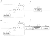
図15は、損失差補償用ファイバを有するマルチモード光増幅器(41、42)を説明する図である。光増幅器(41、42)は、
伝搬モード数がN(Nは2以上の整数)である光ファイバを伝搬する信号光を増幅する増幅用光ファイバ43と、
増幅用光ファイバ43を励起する励起光を送信する励起光源44と、
増幅用ファイバ43を通過した信号光が入力される、少なくとも1つの損失差補償用ファイバ(10、20)と、
を備える。
図15は、損失差補償用ファイバを有するマルチモード光増幅器(41、42)を説明する図である。光増幅器(41、42)は、
伝搬モード数がN(Nは2以上の整数)である光ファイバを伝搬する信号光を増幅する増幅用光ファイバ43と、
増幅用光ファイバ43を励起する励起光を送信する励起光源44と、
増幅用ファイバ43を通過した信号光が入力される、少なくとも1つの損失差補償用ファイバ(10、20)と、
を備える。
マルチモード伝送用の光増幅部47は、増幅用ファイバの希土類分布や励起光の条件によってモード間に利得差が生じるため(例えば、非特許文献6および7を参照。)、光増幅部47のモード間利得差を補償するための損失を付与する必要がある。例えば、実施形態1と2で説明したLP11モードに高い過剰損失を与える損失差補償用ファイバ20、LP21モードに高い過剰損失を与える損失差補償用ファイバ20、LP02モードに高い過剰損失を与える損失差補償用ファイバ10、及び実施形態3で説明したLP01とLP02とのモード変換器25を組み合わせて当該モード間利得差を補償する。
光増幅部47の利得特性と反相関を持つ特性を設計することによって4LPモード光増幅器におけるモード間利得差の低減が可能となる。損失差補償用ファイバの過剰損失特性が光増幅部47の利得特性と反相関の特性であれば、光増幅部47の後段に当該損失差補償用ファイバのみを接続すればよい(図15(A)の光増幅器41)。しかし、単独の損失差補償用ファイバの過剰損失特性が光増幅部47の利得特性と反相関の特性でない場合、複数の損失差補償用ファイバ及びモード変換器を組み合わせ、組み合わせのトータルとして光増幅部47の利得特性と反相関の特性を作り出す(図15(B)の光増幅器42)。
(実施形態5)
本実施形態では、光増幅器(41、42)やマルチモード伝送を行う光増幅部を有する光伝送路において、MDLを改善するために必要な損失差補償用ファイバの種類とその数を見積もる伝送路設計方法について説明する。
本実施形態では、光増幅器(41、42)やマルチモード伝送を行う光増幅部を有する光伝送路において、MDLを改善するために必要な損失差補償用ファイバの種類とその数を見積もる伝送路設計方法について説明する。
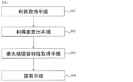
図16は、本伝送路設計方法を説明するフローチャートである。本伝送路設計方法は、 伝搬モード数がN(Nは2以上の整数)である光ファイバを伝搬する信号光を増幅する光増幅部の各伝搬モードの利得を取得する利得取得手順S01と、
前記利得取得手順で取得した利得のうち最小利得の伝搬モードと他の伝搬モードとの利得差ΔGLPmn(mnはモード番号)を算出する利得差算出手順S02と、
前記他の伝搬モードのうちのひとつに対して過剰損失を与える損失補償器i(iはN-1以下の自然数)をそれぞれni台用意し、損失補償器i毎に各伝搬モード(LPmn)に与える損失αi_LPmnを取得する損失補償器特性取得手順S03と、
前記伝搬モード毎に、前記光増幅器の利得と全ての前記損失補償器iで与えられる損失の合計(ΔDMGLPmn)を算出し、
(a)いずれのΔDMGLPmnも10dB以下、且つ
(b)ΔDMGLPmnの最大値と最小値の差MDLが最小
となる、それぞれの前記損失補償器iの数niを見出す探索手順S04と、
を行う。
前記利得取得手順で取得した利得のうち最小利得の伝搬モードと他の伝搬モードとの利得差ΔGLPmn(mnはモード番号)を算出する利得差算出手順S02と、
前記他の伝搬モードのうちのひとつに対して過剰損失を与える損失補償器i(iはN-1以下の自然数)をそれぞれni台用意し、損失補償器i毎に各伝搬モード(LPmn)に与える損失αi_LPmnを取得する損失補償器特性取得手順S03と、
前記伝搬モード毎に、前記光増幅器の利得と全ての前記損失補償器iで与えられる損失の合計(ΔDMGLPmn)を算出し、
(a)いずれのΔDMGLPmnも10dB以下、且つ
(b)ΔDMGLPmnの最大値と最小値の差MDLが最小
となる、それぞれの前記損失補償器iの数niを見出す探索手順S04と、
を行う。
(1)利得取得手順S01
はじめに、光増幅部(例えば、増幅用光ファイバ)にて発生する各伝搬モードの利得の値を求める。利得を実測してもよいし、光増幅部の仕様から取得してもよい。
はじめに、光増幅部(例えば、増幅用光ファイバ)にて発生する各伝搬モードの利得の値を求める。利得を実測してもよいし、光増幅部の仕様から取得してもよい。
(2)利得差算出手順S02
伝搬モードが2モードの場合、伝搬モード間の利得差を算出する。伝搬モードが3モード以上の場合、各伝搬モードの利得と利得が最も小さいモードとの利得差を算出する。
伝搬モードが2モードの場合、伝搬モード間の利得差を算出する。伝搬モードが3モード以上の場合、各伝搬モードの利得と利得が最も小さいモードとの利得差を算出する。
(3)損失補償器特性取得手順S03
伝搬モードが2モードの場合、算出した利得差を補償器の損失差で割り、補償器の数を決定する。
伝搬モードが3モード以上の場合、利得が最小の伝搬モード以外の伝搬モードに過剰損失を与えられる補償器をそれぞれ用意し、MDLが最小となる補償器の数の組み合わせniを求める。
伝搬モードが2モードの場合、算出した利得差を補償器の損失差で割り、補償器の数を決定する。
伝搬モードが3モード以上の場合、利得が最小の伝搬モード以外の伝搬モードに過剰損失を与えられる補償器をそれぞれ用意し、MDLが最小となる補償器の数の組み合わせniを求める。
本伝送路設計方法を具体的に説明する。
なお、実施形態1~3で示した損失値は界分布の重なり積分から求めたものであり、接続点一箇所の損失値である。補償器をファイバで接続する際には、入射部と出射部の2箇所でモード不整合が生じるため、以下では2倍にした損失値を用いる。
なお、実施形態1~3で示した損失値は界分布の重なり積分から求めたものであり、接続点一箇所の損失値である。補償器をファイバで接続する際には、入射部と出射部の2箇所でモード不整合が生じるため、以下では2倍にした損失値を用いる。
非特許文献7に記載の利得スペクトルから波長1546nmの利得を補償する例を示す。
(利得取得手順及び利得差算出手順)
光増幅器での利得は、LP01>LP11>LP21>LP02モードの順で高くなっており、利得が最小となるLP02との利得差は、それぞれΔGLP01=4.1dB、ΔGLP11=2.0dB、ΔGLP21=0.4dBとなる。
(利得取得手順及び利得差算出手順)
光増幅器での利得は、LP01>LP11>LP21>LP02モードの順で高くなっており、利得が最小となるLP02との利得差は、それぞれΔGLP01=4.1dB、ΔGLP11=2.0dB、ΔGLP21=0.4dBとなる。
(損失補償器特性取得手順)
補償器1として、LP01モードの補償器である、図14中のa2/a1=0.02の構造、およびその前後にLP01LP02モード交換部、を用いるとすると、各モードの損失は、
(α1 LP01, α1 LP11,α1 LP21,α1 LP02)
=(0.195, 1.8×10⁻⁶, 2.6×10⁻⁶, 0.076)
となる。
補償器2および3として、実施形態2で示したLP11、21モードの補償器を用いる。a1=7.2μm、a2-a3=2μm、Δ1=0.7%、Δ2=1.2%とし、それぞれ図9中のa2/a1=0.27、a2/a1=0.46の構造を用いるとすると、各モードの損失は
(α2 LP01、α2 LP11、α2 LP21、α2 LP02)=(0.376、0.700、0.359、0.331)、
(α3 LP01、α3 LP11、α3 LP21、α3 LP02)=(0.272、0.223、0.473、0.144)
となる。
補償器1として、LP01モードの補償器である、図14中のa2/a1=0.02の構造、およびその前後にLP01LP02モード交換部、を用いるとすると、各モードの損失は、
(α1 LP01, α1 LP11,α1 LP21,α1 LP02)
=(0.195, 1.8×10⁻⁶, 2.6×10⁻⁶, 0.076)
となる。
補償器2および3として、実施形態2で示したLP11、21モードの補償器を用いる。a1=7.2μm、a2-a3=2μm、Δ1=0.7%、Δ2=1.2%とし、それぞれ図9中のa2/a1=0.27、a2/a1=0.46の構造を用いるとすると、各モードの損失は
(α2 LP01、α2 LP11、α2 LP21、α2 LP02)=(0.376、0.700、0.359、0.331)、
(α3 LP01、α3 LP11、α3 LP21、α3 LP02)=(0.272、0.223、0.473、0.144)
となる。
(探索手順)
伝搬モード毎に、増幅器の利得と補償器で与えられる過剰損失の合計(ΔDMGLPmn)を算出する(数3)。そして、それらの過剰損失の最大値と最小値の差MDLが、少なくとも各モードの損失の合計が10dB以下の領域内で最小となるような各補償器の数(ni)を算出する(数4)。
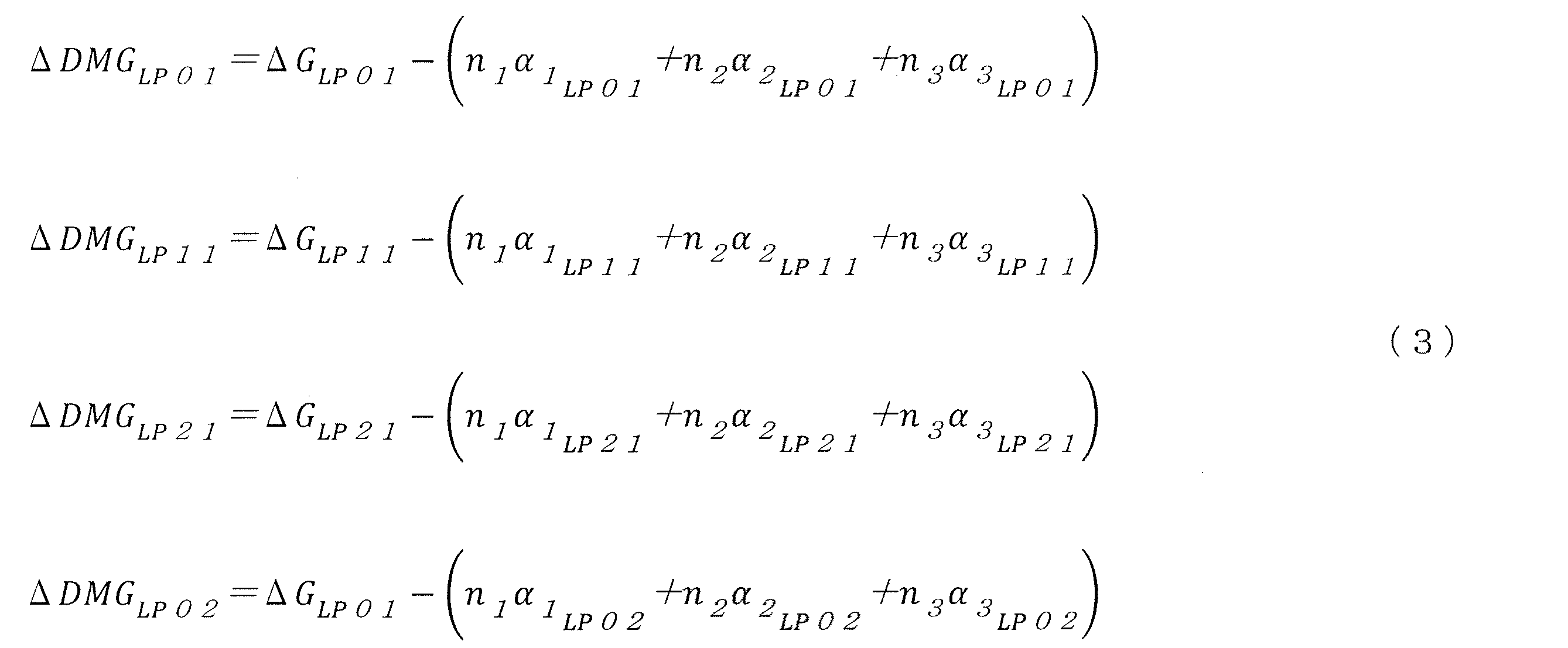

伝搬モード毎に、増幅器の利得と補償器で与えられる過剰損失の合計(ΔDMGLPmn)を算出する(数3)。そして、それらの過剰損失の最大値と最小値の差MDLが、少なくとも各モードの損失の合計が10dB以下の領域内で最小となるような各補償器の数(ni)を算出する(数4)。
例えば、n1=24、n2=9、n3=6とすると、MDLを最小とすることができ、非特許文献7に記載のモード間利得差を0.075dBに抑制できる。
1:コア
3:空洞部
5:クラッド
7:高屈折率部
10、20:モード間損失差補償用ファイバ
25、25’:モード変換器
30:モード損失差補償器
41、42:光増幅器
43:増幅用光ファイバ
44:励起光源
47:光増幅部
3:空洞部
5:クラッド
7:高屈折率部
10、20:モード間損失差補償用ファイバ
25、25’:モード変換器
30:モード損失差補償器
41、42:光増幅器
43:増幅用光ファイバ
44:励起光源
47:光増幅部
Claims (8)
- 伝搬モード数がN(Nは2以上の整数)である光ファイバに挿入されるモード間損失差補償用ファイバであって、
クラッド部、及び前記クラッド部に対する比屈折率差がΔ1である半径a1のコア部で構成され、
光の伝搬方向に第1区間と第2区間があり、
前記第1区間では、断面において前記コア部の領域の一部に半径a2(a2<a1)の空洞部が形成され、
前記第2区間では、断面において前記コア部の領域には空洞部が形成されておらず、
前記伝搬モードの内、特定の伝搬モードに他の伝搬モードより大きい損失を与えることを特徴とするモード間損失差補償用ファイバ。 - 前記コア部の半径a1をX軸、比屈折率差Δ1をY軸としたXY平面において、
A1(5.6,0.65)
B1(5.4,0.55)
C1(5.33,0.53)
D1(5.5,0.51)
E1(6.0,0.45)
F1(6.5,0.41)
G1(7.0,0.38)
H1(7.55,0.36)
I1(7.0,0.42)
J1(6.5,0.48)
K1(6.0,0.575)
を頂点とする多角形で囲まれる領域に前記コア部の半径a1及び比屈折率差Δ1があり、且つa2/a1<0.235を満たす前記空洞部の半径a2が設定されていることを特徴とする請求項1に記載のモード間損失差補償用ファイバ。 - 伝搬モード数がN(Nは2以上の整数)である光ファイバに挿入されるモード間損失差補償用ファイバであって、
クラッド部、及び前記クラッド部に対する比屈折率差がΔ1である半径a1のコア部で構成され、
光の伝搬方向に第1区間と第2区間があり、
前記第1区間では、断面において前記コア部の領域に、前記クラッド部に対する比屈折率差がΔ2である、内環径a2且つ外環径a3(a2<a3<a1)のリング形状の高屈折率部が形成され、
前記第2区間では、断面において前記コア部の領域にはリング形状の高屈折率部が形成されず、
前記伝搬モードの内、特定の伝搬モードに他の伝搬モードより大きい損失を与えることを特徴とするモード間損失差補償用ファイバ。 - 前記コア部の半径a1をX軸、比屈折率差Δ1をY軸としたXY平面において、
A2(6.0,1.02)
B2(5.9,0.95)
C2(6.5,0.80)
D2(7.0,0.71)
E2(7.75,0.61)
F2(7.0,0.75)
G2(6.5,0.88)
を頂点とする多角形で囲まれる領域に前記コア部の半径a1及び比屈折率差Δ1があり、且つ
-0.02(Δ2―Δ1)+0.22<a2/a1<-0.19(Δ2―Δ1)+0.41
を満たす前記リング形状の高屈折率部の半径a2及び比屈折率差Δ2が設定されていることを特徴とする請求項3に記載のモード間損失差補償用ファイバ。 - 前記コア部の半径a1をX軸、比屈折率差Δ1をY軸としたXY平面において、
A2(6.0,1.02)
B2(5.9,0.95)
C2(6.5,0.80)
D2(7.0,0.71)
E2(7.75,0.61)
F2(7.0,0.75)
G2(6.5,0.88)
を頂点とする多角形で囲まれる領域に前記コア部の半径a1及び比屈折率差Δ1があり、且つ
X <a2/a1<-0.09(Δ2-Δ1)+0.56
を満たす前記リング形状の高屈折率部の半径a2及び比屈折率差Δ2が設定されていることを特徴とする請求項3に記載のモード間損失差補償用ファイバ。
ただし、Xは
Δ2―Δ1<0.4のとき、X=-0.04(Δ2―Δ1)+0.35
0.4<Δ2―Δ1<0.6のとき、X=0.35(Δ2―Δ1)+0.20
0.6<Δ2―Δ1<1.2のとき、X=0.07(Δ2―Δ1)+0.36
である。 - 前記第1区間の前段に前記他の伝搬モードのひとつと前記特定のモードとを変換するモード変換部を有することを特徴とする請求項1から5のいずれかに記載のモード間損失差補償用ファイバ。
- 伝搬モード数がN(Nは2以上の整数)である光ファイバを伝搬する信号光を増幅する増幅用光ファイバと、
前記増幅用光ファイバを励起する励起光を送信する励起光源と、
前記増幅用光ファイバを通過した信号光が入力される、少なくとも1つの請求項1から6のいずれかに記載のモード間損失差補償用ファイバと、
を備える光増幅器。 - 伝搬モード数がN(Nは2以上の整数)である光ファイバを伝搬する信号光を増幅する光増幅器の各伝搬モードの利得を取得する利得取得手順と、
前記利得取得手順で取得した利得のうち最小利得の伝搬モードと他の伝搬モードとの利得差ΔGLPmn(mnはモード番号)を算出する利得差算出手順と、
前記他の伝搬モードのうちのひとつに対して過剰損失を与える損失補償器i(iはN-1以下の自然数)をそれぞれni台用意し、損失補償器i毎に各伝搬モード(LPmn)に与える損失αi_LPmnを取得する損失補償器特性取得手順と、
前記伝搬モード毎に、前記光増幅器の利得と全ての前記損失補償器iで与えられる損失の合計(ΔDMGLPmn)を算出し、
(a)いずれのΔDMGLPmnも10dB以下、且つ
(b)ΔDMGLPmnの最大値と最小値の差MDLが最小
となる、それぞれの前記損失補償器iの数niを見出す探索手順と、
を行う伝送路設計方法。
Priority Applications (1)
| Application Number | Priority Date | Filing Date | Title |
|---|---|---|---|
| US17/266,181 US20210234326A1 (en) | 2018-08-07 | 2019-08-06 | Intermode loss difference compensation fiber, optical amplifier, and transmission path design method |
Applications Claiming Priority (2)
| Application Number | Priority Date | Filing Date | Title |
|---|---|---|---|
| JP2018148082A JP7095473B2 (ja) | 2018-08-07 | 2018-08-07 | モード間損失差補償用ファイバ、および光増幅器 |
| JP2018-148082 | 2018-08-07 |
Publications (1)
| Publication Number | Publication Date |
|---|---|
| WO2020032016A1 true WO2020032016A1 (ja) | 2020-02-13 |
Family
ID=69414788
Family Applications (1)
| Application Number | Title | Priority Date | Filing Date |
|---|---|---|---|
| PCT/JP2019/030877 Ceased WO2020032016A1 (ja) | 2018-08-07 | 2019-08-06 | モード間損失差補償用ファイバ、光増幅器、および伝送路設計方法 |
Country Status (3)
| Country | Link |
|---|---|
| US (1) | US20210234326A1 (ja) |
| JP (1) | JP7095473B2 (ja) |
| WO (1) | WO2020032016A1 (ja) |
Cited By (2)
| Publication number | Priority date | Publication date | Assignee | Title |
|---|---|---|---|---|
| JPWO2021166107A1 (ja) * | 2020-02-19 | 2021-08-26 | ||
| JPWO2023073881A1 (ja) * | 2021-10-28 | 2023-05-04 |
Families Citing this family (6)
| Publication number | Priority date | Publication date | Assignee | Title |
|---|---|---|---|---|
| WO2021214976A1 (ja) * | 2020-04-24 | 2021-10-28 | 日本電信電話株式会社 | モード間損失差補償器 |
| US20230305223A1 (en) * | 2020-08-05 | 2023-09-28 | Nippon Telegraph And Telephone Corporation | Optical connector |
| CN112099128A (zh) * | 2020-09-23 | 2020-12-18 | 北京交通大学 | 一种分层掺杂的阶跃型弱耦合增益均衡四模掺铒光纤 |
| CN115129917B (zh) * | 2022-06-06 | 2024-04-09 | 武汉大学 | 一种基于模态共有特征的光学-sar遥感图像跨模态检索方法 |
| CN115986537B (zh) * | 2023-03-14 | 2023-08-22 | 武汉长进光子技术股份有限公司 | 一种基于高斯掺杂环芯少模光纤的纤芯泵浦光纤放大器 |
| CN116822165B (zh) * | 2023-06-07 | 2024-09-20 | 淮阴工学院 | 一种补偿环形光纤内凹损伤破坏轨道角动量模式的方法及系统 |
Citations (7)
| Publication number | Priority date | Publication date | Assignee | Title |
|---|---|---|---|---|
| US6434311B1 (en) * | 1999-06-10 | 2002-08-13 | Lasercomm Inc. | Reducing mode interference in transmission of a high order mode in optical fibers |
| JP2005266808A (ja) * | 2004-03-16 | 2005-09-29 | Draka Comteq Bv | 高次モードを使用するsバンドにおける色分散補償光ファイバ |
| US20070206912A1 (en) * | 2005-11-03 | 2007-09-06 | Aculight Corporation | Apparatus and method for a waveguide with an index profile manifesting a central dip for better energy extraction |
| JP2016537659A (ja) * | 2013-01-29 | 2016-12-01 | オーエフエス ファイテル,エルエルシー | ホログラムを組み込まれた光導波路 |
| JP2017157757A (ja) * | 2016-03-03 | 2017-09-07 | 日本電信電話株式会社 | 増幅用光ファイバ及び光増幅器 |
| WO2018008635A1 (ja) * | 2016-07-04 | 2018-01-11 | 日本電信電話株式会社 | 光ファイバ及び光伝送システム |
| WO2018025847A1 (ja) * | 2016-08-03 | 2018-02-08 | 日本電信電話株式会社 | モード間損失差補償器及び光増幅器 |
Family Cites Families (3)
| Publication number | Priority date | Publication date | Assignee | Title |
|---|---|---|---|---|
| US6766088B2 (en) * | 2000-05-01 | 2004-07-20 | Sumitomo Electric Industries, Ltd. | Optical fiber and method for making the same |
| JP3870713B2 (ja) * | 2001-04-25 | 2007-01-24 | 住友電気工業株式会社 | 光ファイバの端部構造および光ファイバ |
| US8620125B2 (en) * | 2011-04-29 | 2013-12-31 | Corning Incorporated | Light diffusing fibers and methods for making the same |
-
2018
- 2018-08-07 JP JP2018148082A patent/JP7095473B2/ja active Active
-
2019
- 2019-08-06 WO PCT/JP2019/030877 patent/WO2020032016A1/ja not_active Ceased
- 2019-08-06 US US17/266,181 patent/US20210234326A1/en not_active Abandoned
Patent Citations (7)
| Publication number | Priority date | Publication date | Assignee | Title |
|---|---|---|---|---|
| US6434311B1 (en) * | 1999-06-10 | 2002-08-13 | Lasercomm Inc. | Reducing mode interference in transmission of a high order mode in optical fibers |
| JP2005266808A (ja) * | 2004-03-16 | 2005-09-29 | Draka Comteq Bv | 高次モードを使用するsバンドにおける色分散補償光ファイバ |
| US20070206912A1 (en) * | 2005-11-03 | 2007-09-06 | Aculight Corporation | Apparatus and method for a waveguide with an index profile manifesting a central dip for better energy extraction |
| JP2016537659A (ja) * | 2013-01-29 | 2016-12-01 | オーエフエス ファイテル,エルエルシー | ホログラムを組み込まれた光導波路 |
| JP2017157757A (ja) * | 2016-03-03 | 2017-09-07 | 日本電信電話株式会社 | 増幅用光ファイバ及び光増幅器 |
| WO2018008635A1 (ja) * | 2016-07-04 | 2018-01-11 | 日本電信電話株式会社 | 光ファイバ及び光伝送システム |
| WO2018025847A1 (ja) * | 2016-08-03 | 2018-02-08 | 日本電信電話株式会社 | モード間損失差補償器及び光増幅器 |
Cited By (9)
| Publication number | Priority date | Publication date | Assignee | Title |
|---|---|---|---|---|
| JPWO2021166107A1 (ja) * | 2020-02-19 | 2021-08-26 | ||
| WO2021166107A1 (ja) * | 2020-02-19 | 2021-08-26 | 日本電信電話株式会社 | 希土類添加ファイバ及び光ファイバ増幅器 |
| CN115066812A (zh) * | 2020-02-19 | 2022-09-16 | 日本电信电话株式会社 | 稀土类添加光纤和光纤放大器 |
| JP7338780B2 (ja) | 2020-02-19 | 2023-09-05 | 日本電信電話株式会社 | 希土類添加ファイバ及び光ファイバ増幅器 |
| CN115066812B (zh) * | 2020-02-19 | 2025-12-16 | 恩梯梯株式会社 | 稀土类添加光纤和光纤放大器 |
| US12586973B2 (en) | 2020-02-19 | 2026-03-24 | Ntt, Inc. | Rare earth doped fiber and fiber optic amplifier |
| JPWO2023073881A1 (ja) * | 2021-10-28 | 2023-05-04 | ||
| WO2023073881A1 (ja) * | 2021-10-28 | 2023-05-04 | 日本電信電話株式会社 | モード変換器及びモード変換器を含む光部品 |
| JP7754186B2 (ja) | 2021-10-28 | 2025-10-15 | Ntt株式会社 | モード変換器及びモード変換器を含む光部品 |
Also Published As
| Publication number | Publication date |
|---|---|
| JP2020024271A (ja) | 2020-02-13 |
| JP7095473B2 (ja) | 2022-07-05 |
| US20210234326A1 (en) | 2021-07-29 |
Similar Documents
| Publication | Publication Date | Title |
|---|---|---|
| JP7095473B2 (ja) | モード間損失差補償用ファイバ、および光増幅器 | |
| US10782478B2 (en) | Inter-mode loss difference compensator and optical amplifier | |
| JP6046717B2 (ja) | モード変換を用いる少モード化ファイバデバイス | |
| JP7359296B2 (ja) | モード間損失差補償器 | |
| JP6059560B2 (ja) | マルチモード伝送用光増幅器 | |
| JP5059797B2 (ja) | 光ファイバ、光ファイバの設計方法及び光波長多重通信システム | |
| JP2008224969A (ja) | 光ファイバおよび光ファイバ伝送路 | |
| CN109313307B (zh) | 光纤和光传输系统 | |
| JP6368279B2 (ja) | 数モード光ファイバ、及び光ファイバ伝送システム | |
| JP6571562B2 (ja) | 増幅用光ファイバの設計方法 | |
| WO2019026906A1 (ja) | 光ファイバ及び光伝送システム | |
| JP6353351B2 (ja) | 光増幅器 | |
| JP6939728B2 (ja) | マルチモード光増幅器 | |
| JP6005472B2 (ja) | 光ファイバ | |
| JP6824814B2 (ja) | 損失差補償器 | |
| JP6654064B2 (ja) | モード変換器、光増幅器及び光伝送システム | |
| JP2006293117A (ja) | 光ファイバおよびそれを用いた光通信システム | |
| JP7754186B2 (ja) | モード変換器及びモード変換器を含む光部品 | |
| JP2008209654A (ja) | 光通信システム | |
| JP7468664B2 (ja) | 光コネクタ | |
| JP7480853B2 (ja) | モード変換器及び光伝送システム | |
| JP7338780B2 (ja) | 希土類添加ファイバ及び光ファイバ増幅器 | |
| JP2023032196A (ja) | 光モード変換器及び光モード合分波器 | |
| JP6323913B2 (ja) | 光増幅器及び伝送システム |
Legal Events
| Date | Code | Title | Description |
|---|---|---|---|
| 121 | Ep: the epo has been informed by wipo that ep was designated in this application |
Ref document number: 19846935 Country of ref document: EP Kind code of ref document: A1 |
|
| NENP | Non-entry into the national phase |
Ref country code: DE |
|
| 122 | Ep: pct application non-entry in european phase |
Ref document number: 19846935 Country of ref document: EP Kind code of ref document: A1 |