WO2020031470A1 - ガラス基板切断装置及びガラス基板切断方法 - Google Patents
ガラス基板切断装置及びガラス基板切断方法 Download PDFInfo
- Publication number
- WO2020031470A1 WO2020031470A1 PCT/JP2019/021393 JP2019021393W WO2020031470A1 WO 2020031470 A1 WO2020031470 A1 WO 2020031470A1 JP 2019021393 W JP2019021393 W JP 2019021393W WO 2020031470 A1 WO2020031470 A1 WO 2020031470A1
- Authority
- WO
- WIPO (PCT)
- Prior art keywords
- glass substrate
- roller
- blade
- cutting
- protective film
- Prior art date
- Legal status (The legal status is an assumption and is not a legal conclusion. Google has not performed a legal analysis and makes no representation as to the accuracy of the status listed.)
- Ceased
Links
Images







Classifications
-
- B—PERFORMING OPERATIONS; TRANSPORTING
- B28—WORKING CEMENT, CLAY, OR STONE
- B28D—WORKING STONE OR STONE-LIKE MATERIALS
- B28D5/00—Fine working of gems, jewels, crystals, e.g. of semiconductor material; apparatus or devices therefor
-
- C—CHEMISTRY; METALLURGY
- C03—GLASS; MINERAL OR SLAG WOOL
- C03B—MANUFACTURE, SHAPING, OR SUPPLEMENTARY PROCESSES
- C03B33/00—Severing cooled glass
- C03B33/02—Cutting or splitting sheet glass or ribbons; Apparatus or machines therefor
- C03B33/023—Cutting or splitting sheet glass or ribbons; Apparatus or machines therefor the sheet or ribbon being in a horizontal position
-
- C—CHEMISTRY; METALLURGY
- C03—GLASS; MINERAL OR SLAG WOOL
- C03B—MANUFACTURE, SHAPING, OR SUPPLEMENTARY PROCESSES
- C03B33/00—Severing cooled glass
- C03B33/02—Cutting or splitting sheet glass or ribbons; Apparatus or machines therefor
- C03B33/023—Cutting or splitting sheet glass or ribbons; Apparatus or machines therefor the sheet or ribbon being in a horizontal position
- C03B33/033—Apparatus for opening score lines in glass sheets
-
- Y—GENERAL TAGGING OF NEW TECHNOLOGICAL DEVELOPMENTS; GENERAL TAGGING OF CROSS-SECTIONAL TECHNOLOGIES SPANNING OVER SEVERAL SECTIONS OF THE IPC; TECHNICAL SUBJECTS COVERED BY FORMER USPC CROSS-REFERENCE ART COLLECTIONS [XRACs] AND DIGESTS
- Y02—TECHNOLOGIES OR APPLICATIONS FOR MITIGATION OR ADAPTATION AGAINST CLIMATE CHANGE
- Y02P—CLIMATE CHANGE MITIGATION TECHNOLOGIES IN THE PRODUCTION OR PROCESSING OF GOODS
- Y02P40/00—Technologies relating to the processing of minerals
- Y02P40/50—Glass production, e.g. reusing waste heat during processing or shaping
- Y02P40/57—Improving the yield, e-g- reduction of reject rates
Definitions
- the present invention relates to a glass substrate cutting device and a glass substrate cutting method for cutting a glass substrate such as a display device.
- Flat display devices including liquid crystal display devices and organic EL display devices (OLEDs: Organic Electroluminescence Display) are widely used as image display devices for various computers, portable terminal devices, and the like.
- OLEDs Organic Electroluminescence Display
- TFT Thin Film Transistor
- the thin film is usually formed on a glass substrate in a display device manufacturing process.
- a display device manufacturing process thin films for a plurality of products are simultaneously formed on one large glass substrate, and then the large glass substrate is cut. This is because more efficient manufacturing is possible than a method of forming a series of thin films on a glass substrate of one product size.
- the large-sized glass substrate may be cut into a plurality of smaller glass substrates depending on the production line.
- Patent Document 1 discloses a method of cutting a glass substrate at the same time as thinning by inserting a scribe line in a glass substrate and etching the glass substrate.
- the present invention has been made in view of the above problems, and an object of the present invention is to provide a glass substrate cutting apparatus and a glass substrate cutting method capable of cutting a glass substrate having a protective film formed on one surface. .
- One embodiment of the present invention includes a first roller facing one surface of a glass substrate on which a protective film is formed, and a first roller facing the one surface of the glass substrate and cutting the protective film.
- the first roller moves while facing the second roller or the second blade, and the second roller moves while facing the first blade.
- FIG. 3 is a diagram showing a positional relationship among a first head, a second head, and a mother glass substrate having a protective film formed on one surface in a glass substrate cutting apparatus according to an embodiment of the present invention. It is a figure showing the 1st state in the glass substrate cutting device concerning one embodiment of the present invention.
- FIG. 3 is a diagram illustrating an arrangement relationship between a first blade, a second roller, and a mother glass substrate in a first state of the present invention. It is a figure showing the 2nd state in the glass substrate cutting device concerning one embodiment of the present invention.
- FIG. 3 is a diagram showing a positional relationship among a first head, a second head, and a mother glass substrate having a protective film formed on one surface in a glass substrate cutting apparatus according to an embodiment of the present invention. It is a figure showing the 1st state in the glass substrate cutting device concerning one embodiment of the present invention.
- FIG. 3 is a diagram illustrating an arrangement relationship between a first blade, a second roller, and
- FIG. 6 is a diagram illustrating an arrangement relationship between a second blade, a first roller, and a mother glass substrate in a second state of the present invention. It is a figure showing the 3rd state in the glass substrate cutting device concerning one embodiment of the present invention.
- FIG. 8 is a diagram illustrating an arrangement relationship between a first roller, a second roller, and a mother glass substrate in a third state of the present invention. It is a flowchart which shows the glass substrate cutting process in the glass substrate cutting apparatus which concerns on one Embodiment of this invention. 4 is a flowchart illustrating a process of a protective film cutting process in the glass substrate cutting apparatus according to one embodiment of the present invention.
- ⁇ above '' and ⁇ below '' are only when located directly above or directly below a certain component
- FIG. 1 is a schematic view of a glass substrate cutting apparatus 1 according to one embodiment of the present invention.
- the glass substrate cutting apparatus 1 is an apparatus that performs processing for cutting a mother glass substrate 100 that is a large glass substrate. In FIG. 1, illustration of the mother glass substrate 100 is omitted.
- the glass substrate cutting apparatus 1 has a first head 10, a first rail 15, a second head 20, a second rail 25, and a third rail pair 30.
- the first head 10 is connected to the first rail 15. Then, the first head 10 moves in the X direction shown in FIG. 1 according to the trajectory of the first rail 15.
- the second head 20 is connected to the second rail 25. Then, the second head 20 moves in the X direction shown in FIG. 1 according to the trajectory of the second rail 25.
- Both ends of the first rail 15 and both ends of the second rail 25 are connected to the third pair of rails 30, respectively. Then, the first rail 15 and the second rail 25 move in the Y direction shown in FIG. 1 according to the track of the third rail pair 30. That is, the movement of the first head 10 and the second head 20 in the Y direction is performed according to the trajectory of the third pair of rails 30.
- the glass substrate cutting apparatus 1 further includes an actuator (not shown) for driving at least one of the first head 10 and the second head 20.
- This actuator controls the position or pressure of blades and rollers attached to the first head 10 and the second head 20, respectively, in processing in first to third states described later.
- FIG. 2 is a diagram showing a positional relationship between a first head 10, a second head 20, and a mother glass substrate 100 having a protective film 110 formed on one surface in a glass substrate cutting apparatus 1 according to an embodiment of the present invention. It is.
- a protective film 110 is formed on one surface of the mother glass substrate 100.
- the protective film 110 may be provided directly on one surface of the mother glass substrate 100.
- a thin film having a TFT (Thin Film Transistor) substrate, a display element, or the like may be provided between the mother glass substrate 100 and the protective film 110.
- the protective film 110 has a role of protecting a thin film laminated on a glass substrate such as a TFT substrate.
- the other surface of the mother glass substrate 100 is a glass surface.
- the first head 10 is on the side of the protective film 110 formed on one surface of the mother glass substrate 100.
- the second head 20 is on the opposite side to the above-described protective film 110 side. That is, the second head 20 exists on the side opposite to the side on which the first head 10 exists.
- a first blade 11 and a first roller 12 are attached to the first head 10, and a second blade 21 and a second roller 22 are attached to the second head 20.
- the first blade 11 is a blade for cutting the protective film 110 and is attached to one end of the first head 10.
- the first blade 11 is preferably in the form of a rotary blade (rotary cutter). Specifically, a hub blade or a washer-type blade having an annular outer shape may be used.
- the hub blade includes a base formed in a disk shape, and a cutting blade fixed to an outer peripheral portion of the base.
- the cutting blade has a sharp pointed shape, and has a V-shaped cross section as shown in FIGS.
- the angle of the cutting edge of the first blade 11 ( ⁇ 1 shown in FIG. 4) is preferably set in a range of 15 degrees to 45 degrees, and the angle set to an angle of about 30 degrees is preferable. It is more preferred to use.
- the cutting blade of the first blade 11 is not particularly limited as long as it is a blade made of a material used for cutting a normal optical film or the like.
- a material used for cutting a normal optical film or the like for example, iron, iron alloys, steel, metal such as stainless steel, titanium nitride, titanium carbide, tungsten carbide, ceramics and the like, and those having been subjected to a surface treatment such as diamond-like carbon and the like.
- the second blade 21 is a blade for scribing the mother glass substrate 100, and is attached to one end of the second head 20.
- the second blade 21 is preferably in the form of a rotary blade (rotary cutter).
- a hub blade or a washer-type blade having an annular outer shape may be used.
- the hub blade includes a base formed in a disk shape, and a cutting blade fixed to an outer peripheral portion of the base.
- the cutting blade has a shape that is sharp at an obtuse angle, and has a V-shaped cross section as shown in FIG.
- the angle ( ⁇ 2 shown in FIG. 6) of the cutting edge of the second blade 21 is preferably set in the range of 105 ° to 135 °, and the angle set near 120 ° is preferable. It is more preferred to use.
- the cutting edge of the second blade 21 is not particularly limited as long as it is a blade made of a material used for normal glass cutting or scribing.
- a cemented carbide, a sintered diamond (PCD: Poly Crystalline Diamond), etc. are mentioned.
- the first roller 12 supports the mother glass substrate 100 from the side opposite to the second blade 21 during processing by the second blade 21 used as a pair in a first state described later.
- the second roller 22 supports the mother glass substrate 100 from the side opposite to the first blade 11 during processing by the first blade 11 used as a pair in a second state described later. Further, the first roller 12 and the second roller 22 perform a dividing process of the mother glass substrate 100 in a third state described later.
- the first roller 12 and the second roller 22 are made of a rigid body.
- the first roller 12 and the second roller 22 in the present embodiment are made of metal.
- FIGS. 5 and 6 for the processing steps in the second state
- FIGS. 7 and 8 for the processing steps in the third processing.
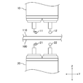
- FIG. 3 is a diagram showing a first state in the glass substrate cutting apparatus 1 according to one embodiment of the present invention.
- FIG. 4 is a diagram illustrating an arrangement relationship between the first blade 11, the second roller 22, and the mother glass substrate 100 in the first state of the present invention.
- the first state is a state in which the first blade 11 and the second roller 22 face each other.
- a protection film cutting process is performed.
- This protective film cutting process is a process in which the first blade 11 cuts the protective film 110 formed on one surface of the mother glass substrate 100 along a predetermined cutting line.
- the first blade 11 and the second roller 22 are set to the use mode.
- the pedestal of the first blade 11 and the pedestal of the second roller 22 are respectively protruded from the position in the normal state to the position in the use mode.
- the first roller 12 does not contact the surface of the protective film 110, and the second blade 21 does not contact the surface of the mother glass substrate 100.
- the first blade 11 and the second roller 22 are moved in one set direction. Specifically, in the case of FIG. 3, the first blade 11 and the second roller 22 move from right to left. During this cutting process, the first blade 11 cuts the protective film 110. Further, the second roller 22 simultaneously moves so as to be directly below the first blade 11, and supports the mother glass substrate 100 as necessary.
- the protection film cutting process in the first state is completed once after confirming that the protection film 110 has been completely cut by performing once or a set multiple times.
- the confirmation at this time may be based on analysis of an image captured by a camera by an image recognition device or the like, or may be visually checked by an operator.
- the first blade 11 is attached to the tip of a horizontal shaft 60 extending from the rotation shaft 50, as shown in FIG.
- the horizontal axis 60 is provided in parallel with a predetermined cutting line in order to align the cutting line of the protective film 110 with the caster effect.
- the actuator controls the first blade 11 in the Z-axis direction shown in FIGS.
- the control in the Z-axis direction in the first state is control of the pressure when cutting the protective film 110 by moving the first blade 11.
- the actuator controls the pressure applied to the protective film 110 from the cutting edge of the first blade 11 in the Z-axis direction shown in FIGS.
- the actuator also controls the second roller 22 in the Z-axis direction as shown in FIGS. 1 and 4 as necessary to appropriately support the mother glass substrate 100.
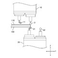
- FIG. 5 is a diagram showing a second state in the glass substrate cutting apparatus 1 according to one embodiment of the present invention.
- FIG. 6 is a diagram showing an arrangement relationship between the second blade 21 and the first roller 12 and the mother glass substrate 100 in the second state of the present invention.
- the second state is a state in which the second blade 21 and the first roller 12 face each other.
- a glass substrate scribing process is performed.
- This glass substrate scribing process is a process in which the second blade 21 scribes the other surface of the mother glass substrate 100 on which the protective film 110 is not formed.
- the second blade 21 and the first roller 12 are set to the use mode.
- the pedestal of the second blade 21 and the pedestal of the first roller 12 are respectively protruded from the normal position to the use mode position.
- the first blade 11 does not contact the surface of the protective film 110
- the second roller 22 does not contact the surface of the mother glass substrate 100.
- the scribing is performed by moving the second blade 21 and the first roller 12 in one direction to be set. Specifically, in the case of FIG. 5, the second blade 21 and the first roller 12 move from right to left. The second blade 21 scribes the mother glass substrate 100 during the scribe processing. The scribe line overlaps with the cutting line of the protective film 110 when viewed in the Z-axis direction, as shown by the dashed line in FIG. In addition, the first roller 12 moves so as to be directly above the second blade 21 and supports the mother glass substrate 100 as necessary. Thereby, the scribe process by the second blade 21 is performed more reliably.
- the glass substrate scribing process in the second state is completed after confirming that the thickness of the glass at the scribed portion is smaller than a predetermined thickness by performing the set multiple times.
- the confirmation at this time may be based on analysis of an image captured by a camera by an image recognition device or the like, or may be visually checked by an operator.
- the second blade 21 is also attached to the tip of a horizontal shaft 60 extending from the rotation shaft 50, similarly to the first blade 11.
- the horizontal axis 60 is provided in parallel with a predetermined scribe line in order to align the scribe line of the mother glass substrate 100 with the caster effect.
- the actuator controls the second blade 21 in the Z-axis direction shown in FIGS.
- the control in the Z-axis direction in the second state is control of the pressure when the mother glass substrate 100 is scribed by the movement of the second blade 21.
- the actuator controls the pressure applied to the mother glass substrate 100 from the cutting edge of the second blade 21 in the Z-axis direction shown in FIGS.
- the actuator also controls the first roller 12 in the Z-axis direction as shown in FIGS. 1 and 6 as needed in order to appropriately support the mother glass substrate 100.
- FIG. 7 is a diagram showing a third state in the glass substrate cutting apparatus 1 according to one embodiment of the present invention.
- FIG. 8 is a diagram showing an arrangement relationship between the first roller 12 and the second roller 22 and the mother glass substrate 100 in the third state of the present invention.
- the third state is a state in which the first roller 12 and the second roller 22 face each other.
- a glass substrate cutting process is performed.
- the glass substrate cutting process is a process of cutting (cutting) the mother glass substrate 100 by applying pressure by the first roller 12 to a portion of the mother glass substrate 100 that has been thinned by the glass substrate scribing process.
- the first roller 12 and the second roller 22 are set to the use mode.
- the pedestal of the first roller 12 and the pedestal of the second roller 22 are respectively protruded from the position in the normal state to the position in the use mode.
- the first blade 11 does not contact the surface of the protective film 110
- the second blade 21 does not contact the surface of the mother glass substrate 100.
- the first roller 12 and the second roller 22 are moved in one direction to be set. Specifically, in the case of FIG. 7, the first roller 12 and the second roller 22 move from right to left.
- the first roller 12 applies a set predetermined pressure to the surface of the protective film 110.
- the mother glass substrate 100 is bent near the scribed portion due to the pressure applied from the first roller 12.
- the second roller 22 comes into contact with the other surface of the mother glass substrate 100 so as to support the bent mother glass substrate 100.
- the glass surface receives a reaction against the pressure applied from the contacting second roller 22.
- the mother glass substrate 100 is divided at a portion of the mother glass substrate 100 that has been thinned by the scribe.
- the second roller 22 is not in contact with the surface of the mother glass substrate 100 as shown in FIG.
- the second roller 22 may be in contact with the other surface of the mother glass substrate 100 from the stage before the first roller 12 applies pressure to the protective film 110.
- the second roller 22 sinks in the Z-axis direction by the amount of flexure applied to the mother glass substrate 100. Thereafter, the second roller 22 may support the mother glass substrate 100 so that the mother glass substrate 100 does not drop at the time of division.
- the glass substrate cutting process in the third state is performed once or a plurality of times set, and is completed after confirming that the mother glass substrate 100 is completely cut.
- the glass substrate cutting process is performed only once, it is checked whether or not the mother glass substrate 100 where the pressure has already been applied is completely cut along with the movement of the first roller 12 and the second roller 22. Then, the first roller 12 and the second roller 22 may be moved to the next location.
- the confirmation at this time may be based on analysis of an image captured by a camera by an image recognition device or the like, or may be visually checked by an operator.
- the actuator controls the first roller 12 in the Z-axis direction shown in FIGS. More specifically, the control is performed so that the height in the Z-axis direction at the time of positioning the first roller 12 before the division does not change during the movement of the mother glass substrate 100 for the division.
- the actuator also controls the second roller 22 in the Z-axis direction as shown in FIGS. 1 and 8 as needed to appropriately support the mother glass substrate 100.
- the mother glass substrate 100 having the protective film 110 formed on one surface is cut through a protective film cutting process, a glass substrate scribing process, and a glass substrate cutting process.
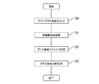
- FIG. 9 is a flowchart showing a glass substrate cutting step in the glass substrate cutting apparatus 1 according to one embodiment of the present invention.
- the mother glass substrate 100 having the protective film 110 formed on one surface, which is cut in the glass substrate cutting step is set between the first head 10 and the second head 20 (S0).
- the mother glass substrate 100 is turned into two glass substrates by the glass substrate cutting step, and is supported by another device (not shown) so as not to fall after cutting.
- An apparatus for supporting these two glass substrates is, for example, a clip-shaped metal fitting or a suction cup.
- a protection film cutting process is performed (S1). After the protection film cutting process, a glass substrate scribing process is performed (S2). After the glass substrate scribing process, a glass substrate cutting process is performed (S3). The two glass substrates cut by the glass substrate cutting process are each carried to an apparatus used in the next step.
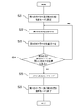
- FIG. 10 is a flowchart showing steps of a protective film cutting process in the glass substrate cutting apparatus 1 according to one embodiment of the present invention.
- alignment is performed so that the set cutting start position of the protective film 110 and the position of the cutting edge of the first blade 11 match (S12).
- This alignment may be automatically performed by an actuator included in the glass substrate cutting device 1, or may be manually set by an operator.
- Positioning is performed on the blade edge of one blade 11.
- the second roller 22 is aligned so that the first blade 11 corresponds to the set position (S13).
- the coordinates determined in S12 may be acquired, and the actuator of the glass substrate cutting apparatus 1 may automatically determine the position of the second roller 22 based on the coordinates.
- the position of the second roller 22 may be manually set by an operator.
- the protection film 110 is cut (S15).
- the use mode set for the first blade 11 and the second roller 22 ends (S16).
- the first blade 11 and the second roller 22 that were in the use mode position return to the normal position.
- the protection film cutting process is performed.
- FIG. 11 is a flowchart showing a glass substrate scribing process in the display device manufacturing apparatus according to one embodiment of the present invention.
- alignment is performed so that the set scribing start position of the mother glass substrate 100 and the position of the cutting edge of the second blade 21 match (S22).
- This positioning may be automatically performed by an actuator of the glass substrate cutting apparatus 1 based on information such as coordinates indicating the position of a cutting line of the protective film 110, or manually set by an operator. It may be.
- the first roller 12 is aligned so that the second blade 21 corresponds to the set position (S23).
- the coordinates indicating the position of the cutting edge of the second blade 21 determined in S22 described above are acquired, and the actuator of the glass substrate cutting apparatus 1 automatically moves the first roller based on the coordinates. Twelve positions may be determined. Alternatively, the position of the first roller 12 may be manually set by an operator.
- the mother glass substrate 100 is scribed (S25).
- the use mode set for the second blade 21 and the first roller 12 ends (S26).
- the second blade 21 and the first roller 12 that have been in the use mode position return to their normal positions.
- the glass substrate scribing process is performed.
- FIG. 12 is a flowchart showing a glass substrate cutting process in the display device manufacturing apparatus according to one embodiment of the present invention.
- the first roller 12 and the second roller 22 are set to a use mode (S31).
- the pedestal of the first roller 12 and the pedestal of the second roller 22 are respectively protruded from the normal position to the use mode position.
- the pressing position of the mother glass substrate 100 set by the first roller 12 is set in advance (S32).
- This alignment may be automatically performed by an actuator included in the glass substrate cutting device 1, or may be manually set by an operator.
- the first roller 12 is aligned based on information such as coordinates indicating a position of a cutting line of the protective film 110 and coordinates indicating a scribe line of the mother glass substrate 100. .
- the second roller 22 is aligned with the set position (S33).
- the actuator of the glass substrate cutting apparatus 1 acquires the coordinates indicating the position of the first roller 12 determined in S32 described above, and determines the position of the second roller 22 based on the coordinates. You may. Alternatively, the position of the second roller 22 may be manually set by an operator.
- the mother glass substrate 100 is cut (S35).
- the use mode set for the first roller 12 or the second roller 22 ends (S36).
- the first roller 12 or the second roller 22 at the position of the use mode returns to the normal position.
- the glass substrate cutting process is performed.
- the glass substrate cutting apparatus described above, and the glass substrate cutting method using the glass substrate cutting apparatus, even for a large glass substrate having a protective film formed on one surface, cutting the glass substrate without using a plurality of apparatuses Becomes possible.
- the configuration in which the protective film is cut is shown, but a film other than the protective film may be formed on the glass substrate.
- the first blade may have a cutting blade capable of cutting the film provided on the glass substrate.
Landscapes
- Chemical & Material Sciences (AREA)
- Engineering & Computer Science (AREA)
- Materials Engineering (AREA)
- Organic Chemistry (AREA)
- Mechanical Engineering (AREA)
- Re-Forming, After-Treatment, Cutting And Transporting Of Glass Products (AREA)
- Processing Of Stones Or Stones Resemblance Materials (AREA)
Abstract
一表面に保護膜が形成されたガラス基板を切断可能なガラス基板切断装置及び表示装置の製造方法を提供する。 保護膜が形成されたガラス基板の一方の面を向く第1のローラと、前記ガラス基板の前記一方の面を向き、前記保護膜を切断するための第1の刃と、前記保護膜が形成されない前記ガラス基板の他方の面を向く第2のローラと、前記ガラス基板の前記他方の面を向き、前記ガラス基板をスクライブするための第2の刃と、を備え、前記第1のローラは、前記第2のローラ又は前記第2の刃と対向しながら移動し、前記第2のローラは、前記第1の刃と対向しながら移動する、ことを特徴とするガラス基板切断装置。
Description
本発明は、表示装置等のガラス基板を切断するガラス基板切断装置及びガラス基板切断方法に関する。
液晶表示装置や有機EL表示装置(OLED:Organic Electroluminescence Display)をはじめとする平面表示装置は、各種コンピュータや携帯用端末装置等のための画像表示装置として広く用いられている。これら平面表示装置は、薄膜トランジスタ(TFT:Thin Film Transistor)等を有する薄膜を利用した表示装置が用いられており、更なる小型化、薄型化が求められている。
該薄膜は、表示装置の製造工程において、通常ガラス基板上に形成される。該製造工程では、1つの大型ガラス基板上に複数の製品分の薄膜を同時に成膜し、その後、該大型ガラス基板を切断することが多い。これは、1製品サイズのガラス基板上に該一連の薄膜を成膜する方法よりも、効率的な製造が可能となるためである。
また、大型ガラス基板上に一連の薄膜を成膜する途中においても、製造ラインの都合により、該大型ガラス基板を切断して複数のより小さいガラス基板に分割することもある。
特許文献1には、ガラス基板にスクライブラインを入れてエッチングすることにより、薄型化と同時に該ガラス基板を切断する方法が開示されている。
上述の大型ガラス基板として一表面に保護膜が形成されたガラス基板を用いる場合、一般的にはガラス基板を切断する装置とは別に、保護膜を切断する装置を導入する必要がある。つまり、ガラス基板切断装置が保護膜を切断する構成を有していないため、一表面に保護膜が形成されたガラス基板の切断ができない。
本発明は、上記問題点に鑑みてなされたものであり、その目的は、一表面に保護膜が形成されたガラス基板を切断可能なガラス基板切断装置及びガラス基板切断方法を提供することにある。
本発明の一実施形態は、保護膜が形成されたガラス基板の一方の面を向く第1のローラと、前記ガラス基板の前記一方の面を向き、前記保護膜を切断するための第1の刃と、前記保護膜が形成されない前記ガラス基板の他方の面を向く第2のローラと、前記ガラス基板の前記他方の面を向き、前記ガラス基板をスクライブするための第2の刃と、を備え、前記第1のローラは、前記第2のローラ又は前記第2の刃と対向しながら移動し、前記第2のローラは、前記第1の刃と対向しながら移動する、ことを特徴とするガラス基板切断装置である。
以下に、本発明の実施形態について、図面を参照しつつ説明する。なお、開示はあくまで一例にすぎず、当業者において、発明の主旨を保っての適宜変更について容易に想到し得るものについては、当然に本発明の範囲に含有されるものである。また、図面は説明をより明確にするため、実際の態様に比べ、各部の幅、厚さ、形状等について模式的に表される場合があるが、あくまで一例であって、本発明の解釈を限定するものではない。また、本明細書と各図において、既出の図に関して前述したものと同様の要素には、同一の符号を付して、詳細な説明を適宜省略することがある。
さらに、本発明の詳細な説明において、ある構成物と他の構成物との位置関係を規定する際、「上に」「下に」とは、ある構成物の直上又は直下に位置する場合のみでなく、特に断りの無い限りは、間にさらに他の構成物を介在する場合を含むものとする。
図1は、本発明の一実施形態に係るガラス基板切断装置1の概略図である。ガラス基板切断装置1は、大型ガラス基板であるマザーガラス基板100を切断するための処理を行う装置である。なお図1では、マザーガラス基板100の図示を省略している。ガラス基板切断装置1は、第1のヘッド10、第1のレール15、第2のヘッド20、第2のレール25及び第3のレール対30を有する。
第1のヘッド10は第1のレール15と接続している。そして、第1のヘッド10は、この第1のレール15が有する軌道に従って、図1に示すX方向への移動を行う。第2のヘッド20は第2のレール25と接続している。そして、第2のヘッド20は、この第2のレール25が有する軌道に従って、図1に示すX方向への移動を行う。
第1のレール15の両端部及び第2のレール25の両端部は、それぞれ第3のレール対30と接続する。そして、第1のレール15及び第2のレール25は、この第3のレール対30が有する軌道に従って、図1に示すY方向への移動を行う。つまり、第1のヘッド10及び第2のヘッド20のY方向への移動は、第3のレール対30が有する軌道に従って行われる。
ガラス基板切断装置1は、図示しないが、さらに、第1のヘッド10又は第2のヘッド20のいずれか少なくとも一方を駆動するアクチュエータを有する。このアクチュエータは、後述する第1乃至第3の状態における処理で、第1のヘッド10及び第2のヘッド20それぞれに取り付けられる刃やローラの位置又は圧力を制御する。
図2は、本発明の一実施形態に係るガラス基板切断装置1における、第1のヘッド10と第2のヘッド20及び一表面に保護膜110を形成したマザーガラス基板100の位置関係を示す図である。
マザーガラス基板100の一表面上には、保護膜110が形成される。保護膜110は、マザーガラス基板100一表面の直上に設けられてもよい。又は、マザーガラス基板100と保護膜110との間に、TFT(Thin Film Transistor)基板や表示素子などを有する薄膜が設けられてもよい。この場合、保護膜110は、TFT基板などガラス基板上に積層した薄膜を保護する役割を担う。対して、マザーガラス基板100のもう一方の表面はガラス面である。
第1のヘッド10は、マザーガラス基板100の一表面に形成される保護膜110の側にある。また、第2のヘッド20は、上述の保護膜110側とは反対側にある。つまり、第1のヘッド10が存在する側とは反対の側に第2のヘッド20が存在する。
第1のヘッド10には、第1の刃11と第1のローラ12が取り付けられ、第2のヘッド20には、第2の刃21と第2のローラ22が取り付けられる。
第1の刃11は、保護膜110を切断するため刃であって、第1のヘッド10の一方の先端部分に取り付けられる。
第1の刃11は、回転刃(ロータリカッター)状であることが好ましい。具体的には、ハブブレードや外形が環状のワッシャ型ブレードなどが挙げられる。ハブブレードの場合、円盤状に形成された基台と、基台の外周部に固定した切り刃とを備える。切り刃は、鋭角に尖った形状をしており、図6及び8で示すように、断面形状がV字状となる。その上で、第1の刃11の切り刃の角度(図4に示すθ1)は、15度から45度の範囲で設定されることが好ましく、30度近傍の角度に設定されたものを使用することがさらに好ましい。また、第1の刃11の切り刃は、通常の光学フィルム等の切断に用いられる材質から成る刃であれば特に限定されるものではない。例えば、鉄、鉄合金、鋼、ステンレス鋼のような金属製や、窒化チタン、炭化チタン、炭化タングステンやセラミック製等が挙げられ、それらにダイヤモンドライクカーボン等などの表面処理を施したもの等が挙げられる。
第2の刃21は、マザーガラス基板100をスクライブするための刃であって、第2のヘッド20の一方の先端部分に取り付けられる。
第2の刃21も、第1の刃11と同様に、回転刃(ロータリカッター)状であることが好ましい。具体的には、ハブブレードや外形が環状のワッシャ型ブレードなどが挙げられる。ハブブレードの場合、円盤状に形成された基台と、基台の外周部に固定した切り刃とを備える。切り刃は、鈍角に尖った形状をしており、図6で示すように、断面形状がV字状となる。その上で、第2の刃21の切り刃の角度(図6に示すθ2)は、105度から135度の範囲で設定されることが好ましく、120度近傍の角度に設定されたものを使用することがさらに好ましい。また、第2の刃21の切り刃は、通常のガラス切断やスクライブ処理に用いられる材質から成る刃であれば特に限定されるものではない。例えば、超硬合金や焼結ダイヤモンド(PCD:Poly Crystalline Diamond)等が挙げられる。
第1のローラ12は、後述する第1の状態において、対となって使用される第2の刃21による加工の際、第2の刃21とは反対側からマザーガラス基板100を支持する。第2のローラ22は、後述する第2の状態において、対となって使用される第1の刃11による加工の際、第1の刃11とは反対側からマザーガラス基板100を支持する。また、第1のローラ12及び第2のローラ22は、後述する第3の状態において、マザーガラス基板100の分断処理を行う。
第1のローラ12及び第2のローラ22は、剛体からなる。例えば、本実施形態における第1のローラ12及び第2のローラ22は金属からなる。
以下、本発明の一実施形態に係るガラス基板切断装置1によるガラス基板切断工程について説明する。なお、第1の状態における処理工程については図3及び4、第2の状態における処理工程については図5及び6、第3の処理における処理工程については、図7及び8を参照する。
図3は、本発明の一実施形態に係るガラス基板切断装置1における、第1の状態を示す図である。図4は、本発明の第1の状態における、第1の刃11及び第2のローラ22とマザーガラス基板100の配置関係を示す図である。
第1の状態とは、第1の刃11と第2のローラ22とが対向する状態である。この第1の状態では、保護膜切断処理が行われる。この保護膜切断処理は、マザーガラス基板100の一表面に形成される保護膜110を、第1の刃11が予定された切断線に沿って切断する処理である。
第1の状態では、第1の刃11及び第2のローラ22が使用モードに設定される。使用モードに設定されると、第1の刃11の台座及び第2のローラ22の台座が、通常時の位置から使用モードの位置までそれぞれせり出される。これにより、第1の状態において、第1のローラ12は保護膜110の表面と接さず、また第2の刃21はマザーガラス基板100の表面と接さない。
その後、保護膜110を切断する際は、第1の刃11及び第2のローラ22を設定する一方向に動かすことで行われる。具体的に、図3の場合は第1の刃11及び第2のローラ22が右から左へと移動する。この切断処理時に第1の刃11が保護膜110の切断を行う。また、第2のローラ22は、第1の刃11の直下にあるよう同時に移動し、必要に応じてマザーガラス基板100を支持する。
第1の状態における保護膜切断処理は、1回又は設定された複数回行われることで、完全に保護膜110が切断されたことを確認した後に完了とする。この時の確認は、画像認識装置などがカメラで撮影した画像の解析によるものでもよく、又は作業者が目視で行ってもよい。
なお、第1の刃11は図2で示すように、回転軸50から延びる水平軸60の先端部分に取り付けられる。この水平軸60は、キャスター効果によって保護膜110の切断線を一直線上とするため、予定された切断線と並行するように設けられる。
この第1の状態では、第1の刃11について、アクチュエータが図1及び4に示すZ軸方向の制御を行う。
第1の状態でのZ軸方向の制御とは、第1の刃11の移動により保護膜110を切断する際の圧力の制御である。具体的には、第1の刃11の刃先から保護膜110にかける圧力を、アクチュエータが図1及び4に示すZ軸方向で制御する。
またアクチュエータは、マザーガラス基板100を適宜支持するため、必要に応じて第2のローラ22についても図1及び4に示すZ軸方向の制御を行う。
図5は、本発明の一実施形態に係るガラス基板切断装置1における、第2の状態を示す図である。図6は、本発明の第2の状態における、第2の刃21及び第1のローラ12とマザーガラス基板100の配置関係を示す図である。
第2の状態とは、第2の刃21と第1のローラ12とが対向する状態である。この第2の状態では、ガラス基板スクライブ処理が行われる。このガラス基板スクライブ処理は、保護膜110が形成されないマザーガラス基板100の他方の面を、第2の刃21がスクライブする処理である。
第2の状態では、第2の刃21及び第1のローラ12が使用モードに設定される。使用モードに設定されると、第2の刃21の台座及び第1のローラ12の台座が、通常時の位置から使用モードの位置までそれぞれせり出される。これにより、第2の状態において、第1の刃11は保護膜110の表面と接さず、また第2のローラ22はマザーガラス基板100の表面と接さない。
その後、マザーガラス基板100をスクライブする際は、第2の刃21及び第1のローラ12を設定する一方向に動かすことで行われる。具体的に、図5の場合は第2の刃21及び第1のローラ12が右から左へと移動する。このスクライブ処理時に第2の刃21がマザーガラス基板100のスクライブを行う。スクライブによる線は、図6で示す一点鎖線のように、Z軸方向から見ると保護膜110の切断線と重複する。また、第1のローラ12は、第2の刃21の直上にあるよう移動し、必要に応じてマザーガラス基板100を支持する。これにより、より確実に第2の刃21によるスクライブ処理が行われる。
第2の状態におけるガラス基板スクライブ処理は、設定された複数回行われることで、スクライブを行った箇所のガラスの厚さが所定の厚さよりも薄くなったことを確認した後に完了とする。この時の確認は、画像認識装置などがカメラで撮影した画像の解析によるものでもよく、又は作業者が目視で行ってもよい。
なお、第2の刃21も第1の刃11と同様に、回転軸50から延びる水平軸60の先端部分に取り付けられる。この水平軸60は、キャスター効果によってマザーガラス基板100のスクライブ線を一直線上とするため、予定されたスクライブ線と並行するように設けられる。
この第2の状態では、第2の刃21について、アクチュエータが図1及び6に示すZ軸方向の制御を行う。
第2の状態でのZ軸方向の制御とは、第2の刃21の移動によりマザーガラス基板100のスクライブする際の圧力の制御である。具体的には、第2の刃21の刃先からマザーガラス基板100にかかる圧力を、アクチュエータが図1及び6に示すZ軸方向で制御する。
またアクチュエータは、マザーガラス基板100を適宜支持するため、必要に応じて第1のローラ12についても図1及び6に示すZ軸方向の制御を行う。
図7は、本発明の一実施形態に係るガラス基板切断装置1における、第3の状態を示す図である。図8は、本発明の第3の状態における、第1のローラ12及び第2のローラ22とマザーガラス基板100の配置関係を示す図である。
第3の状態とは、第1のローラ12と第2のローラ22とが対向する状態である。この第3の状態では、ガラス基板分断処理が行われる。このガラス基板分断処理は、マザーガラス基板100のうち、ガラス基板スクライブ処理によって薄くなった箇所へ、第1のローラ12による圧力を加え、マザーガラス基板100を分断(切断)する処理である。
第3の状態では、第1のローラ12及び第2のローラ22が使用モードに設定される。使用モードに設定されると、第1のローラ12の台座及び第2のローラ22の台座が、通常時の位置から使用モードの位置までそれぞれせり出される。これにより、第3の状態において、第1の刃11は保護膜110の表面と接さず、また第2の刃21はマザーガラス基板100の表面と接さない。
その後、マザーガラス基板100を分断する際は、第1のローラ12及び第2のローラ22を設定する一方向に動かすことで行われる。具体的に、図7の場合は第1のローラ12及び第2のローラ22が右から左へと移動する。
第1のローラ12は、設定された所定の圧力を保護膜110の面へ加える。この際、マザーガラス基板100は、第1のローラ12から加えられた圧力により、スクライブされた箇所の近傍で撓みが生じる。そして、第2のローラ22は、撓んだマザーガラス基板100を支持するように、マザーガラス基板100のもう一方の表面と接する。この時、ガラス面は、接した第2のローラ22から加えられた圧力に対する反作用を受ける。その結果、マザーガラス基板100のうちスクライブによって薄くなった部分において、マザーガラス基板100の分断が起こる。
なお、第1のローラ12が保護膜110へ圧力を加える前の段階では、図8で示すように、第2のローラ22がマザーガラス基板100の表面とは接していない。
また、上述の構成以外に、第1のローラ12が保護膜110へ圧力を加える前の段階から第2のローラ22がマザーガラス基板100のもう一方の表面と接していてもよい。この場合、第1のローラ12が設定された所定の圧力を保護膜110の面へ加えると、第2のローラ22は、マザーガラス基板100に乗じた撓み分だけZ軸方向に沈み込む。その後、第2のローラ22は、分断時にマザーガラス基板100が落下しないように支持するようにしてもよい。
第3の状態におけるガラス基板分断処理は、1回又は設定された複数回行われることで、完全にマザーガラス基板100が分断されたことを確認した後に完了とする。ガラス基板分断処理を1回のみ行う場合は、第1のローラ12及び第2のローラ22の移動に伴って、既に加圧を行った箇所のマザーガラス基板100が完全に分断されているかを確認した上で、次の箇所へ第1のローラ12及び第2のローラ22を移動させる構成としてもよい。この時の確認は、画像認識装置などがカメラで撮影した画像の解析によるものでもよく、又は作業者が目視で行ってもよい。
この第3の状態では、第1のローラ12について、アクチュエータが図1及び8に示すZ軸方向の制御を行う。具体的には、分断前に行う第1のローラ12の位置合わせ時におけるZ軸方向の高さが、マザーガラス基板100の分断のために移動させる間も変化しないように制御する。
またアクチュエータは、マザーガラス基板100を適宜支持するため、必要に応じて第2のローラ22についても図1及び8に示すZ軸方向の制御を行う。
以上のように、一方の表面に保護膜110が形成されたマザーガラス基板100は、保護膜切断処理、ガラス基板スクライブ処理及びガラス基板分断処理を経て切断される。
図9は、本発明の一実施形態に係るガラス基板切断装置1における、ガラス基板切断工程を示すフローチャートである。まず、該ガラス基板切断工程にて切断する、一方の表面に保護膜110が形成されたマザーガラス基板100を第1のヘッド10と第2のヘッド20との間にセットする(S0)。このマザーガラス基板100は、該ガラス基板切断工程により2つのガラス基板となるが、それぞれが切断後落下しないよう、図示しない別の装置によって支持される。これら2つのガラス基板を支持する装置は、例えば、クリップ状の金具や吸着盤などである。
S0で示すようにマザーガラス基板100をセットした後、保護膜切断処理を行う(S1)。保護膜切断処理後は、ガラス基板スクライブ処理を行う(S2)。ガラス基板スクライブ処理後は、ガラス基板分断処理を行う(S3)。ガラス基板分断処理によって切断された2つのガラス基板は、それぞれに次の工程で使用される装置へ運ばれる。
図10は、本発明の一実施形態に係るガラス基板切断装置1における、保護膜切断処理の工程を示すフローチャートである。切断するマザーガラス基板100をセット後、第1の刃11及び第2のローラ22を使用モードに設定する(S11)。これにより、第1の刃11の台座及び第2のローラ22の台座が、通常時の位置から使用モードの位置までそれぞれせり出される。
次に、設定された保護膜110の切断開始位置と第1の刃11の刃先の位置とが合うように位置合わせを行う(S12)。この位置合わせは、ガラス基板切断装置1が有するアクチュエータによって自動的に行われてもよく、作業者によってマニュアル設定されてもよい。アクチュエータによって自動的に行われる場合は、予め作業者がガラス基板切断装置1へ入力した、セットされたマザーガラス基板100の大きさや保護膜110が形成されている箇所等の情報に基づいて、第1の刃11の刃先について位置合わせが行われる。
S12後、第2のローラ22について、第1の刃11が設定された位置と対応するように位置合わせを行う(S13)。この位置合わせは、上述のS12により確定した座標を取得し、ガラス基板切断装置1が有するアクチュエータが該座標に基づいて、自動的に第2のローラ22の位置を決定してもよい。又は、作業者によって、第2のローラ22の位置がマニュアル設定されてもよい。
その後、S12とS13における位置合わせが正常に行われているかを判定する(S14)。設定された位置に第1の刃11又は第2のローラ22もしくはその両方が位置していないと判定された場合(S14:No)は再度S12に戻り、第1の刃11、第2のローラ22の順に位置合わせを行う。
設定された位置に第1の刃11及び第2のローラ22が位置している場合(S14:Yes)は、保護膜110を切断する(S15)。保護膜110の切断が終わると、第1の刃11及び第2のローラ22に設定されていた使用モードを終了する(S16)。これにより、使用モードの位置にあった第1の刃11及び第2のローラ22が通常の位置に戻る。このようにして、保護膜切断処理が行われる。
図11は、本発明の一実施形態に係る表示装置の製造装置における、ガラス基板スクライブ処理の工程を示すフローチャートである。保護膜切断処理を完了した後、第2の刃21及び第1のローラ12を使用モードに設定する(S21)。これにより、第2の刃21の台座及び第1のローラ12の台座が、通常時の位置から使用モードの位置までそれぞれせり出される。
次に、設定されたマザーガラス基板100のスクライブ開始位置と第2の刃21の刃先の位置とが合うように位置合わせを行う(S22)。この位置合わせは、ガラス基板切断装置1が有するアクチュエータが保護膜110の切断線の位置を示す座標などの情報に基づいて自動的に行うものであってもよく、作業者によってマニュアル設定されるものであってもよい。
S22後、第1のローラ12について、第2の刃21が設定された位置と対応するように位置合わせを行う(S23)。この位置合わせは、上述のS22により確定した、第2の刃21の刃先の位置を示す座標を取得し、ガラス基板切断装置1が有するアクチュエータが該座標に基づいて、自動的に第1のローラ12の位置を決定してもよい。又は、作業者によって、第1のローラ12の位置がマニュアル設定されるものであってもよい。
その後、S22とS23における位置合わせが正常に行われているかを判定する(S24)。設定された位置に第2の刃21又は第1のローラ12もしくはその両方が位置していないと判定された場合(S24:No)は再度S22に戻り、第2の刃21、第1のローラ12の順に位置合わせを行う。
設定された位置に第2の刃21及び第1のローラ12が位置している場合(S24:Yes)は、マザーガラス基板100をスクライブする(S25)。マザーガラス基板100のスクライブが終わると、第2の刃21及び第1のローラ12に設定されていた使用モードを終了する(S26)。これにより、使用モードの位置にあった第2の刃21及び第1のローラ12が通常の位置に戻る。このようにして、ガラス基板スクライブ処理が行われる。
図12は、本発明の一実施形態に係る表示装置の製造装置における、ガラス基板分断処理の工程を示すフローチャートである。ガラス基板スクライブ処理を完了した後、第1のローラ12及び第2のローラ22を使用モードに設定する(S31)。これにより、第1のローラ12の台座及び第2のローラ22の台座が、通常時の位置から使用モードの位置までそれぞれせり出される。
次に、予め設定された、第1のローラ12によるマザーガラス基板100の加圧位置の位置合わせを行う(S32)。この位置合わせは、ガラス基板切断装置1が有するアクチュエータによって自動的に行われてもよく、作業者によってマニュアル設定されてもよい。アクチュエータによって自動的に行われる場合は、保護膜110の切断線の位置を示す座標及びマザーガラス基板100のスクライブ線を示す座標などの情報に基づいて、第1のローラ12の位置合わせが行われる。
S32後、第1のローラ12による圧力で撓んだマザーガラス基板100を支持するため、第2のローラ22について設定された位置への位置合わせを行う(S33)。この位置合わせは、上述のS32により確定した、第1のローラ12の位置を示す座標をガラス基板切断装置1が有するアクチュエータが取得し、該座標に基づいて第2のローラ22の位置を決定してもよい。又は、作業者によって第2のローラ22の位置がマニュアル設定されるものであってもよい。
その後、S32とS33における位置合わせが正常に行われているかを判定する(S34)。設定された位置に第1のローラ12又は第2のローラ22もしくはその両方が位置していないと判定された場合(S34:No)は再度S32に戻り、第1のローラ12、第2のローラ22の順に位置合わせを行う。
設定された位置に第1のローラ12及び第2のローラ22が位置している場合(S34:Yes)は、マザーガラス基板100を分断する(S35)。マザーガラス基板100の分断が終わると、第1のローラ12又は第2のローラ22に設定されていた使用モードを終了する(S36)。これにより、使用モードの位置にあった第1のローラ12又は第2のローラ22が通常の位置に戻る。このようにして、ガラス基板分断処理が行われる。
上述のガラス基板切断装置、及び該ガラス基板切断装置を用いたガラス基板切断方法により、一表面に保護膜が形成された大型のガラス基板についても、複数の装置を使用することなくガラス基板の切断が可能となる。なお、本実施形態では、保護膜を切断する構成を示したが、保護膜以外の膜をガラス基板上に形成してもよい。その場合、第1の刃は、該ガラス基板上に設けた該膜を切断可能な切り刃を有する構成とすればよい。
本発明の思想の範疇において、当業者であれば、各種の変更例及び修正例に想到し得るものであり、それら変更例及び修正例についても本発明の範囲に属するものと了解される。例えば、前述の各実施形態に対して、当業者が適宜、構成要素の追加、削除若しくは設計変更を行ったもの、又は、工程の追加、省略若しくは条件変更を行ったものも、本発明の要旨を備えている限り、本発明の範囲に含まれる。
Claims (4)
- 保護膜が形成されたガラス基板の一方の面を向く第1のローラと、
前記ガラス基板の前記一方の面を向き、前記保護膜を切断するための第1の刃と、
前記保護膜が形成されない前記ガラス基板の他方の面を向く第2のローラと、
前記ガラス基板の前記他方の面を向き、前記ガラス基板をスクライブするための第2の刃と、を備え、
前記第1のローラは、前記第2のローラ又は前記第2の刃と対向しながら移動し、
前記第2のローラは、前記第1の刃と対向しながら移動する、
ことを特徴とするガラス基板切断装置。 - 請求項1に記載のガラス基板切断装置において、
前記第1の刃と前記第1のローラが取り付けられる第1のヘッドと、
前記第2の刃と前記第2のローラが取り付けられる第2のヘッドと、
前記第1の刃と前記第2のローラとが対向する第1の状態、前記第2の刃と第1のローラとが対向する第2の状態、又は前記第1のローラと前記第2のローラとが対向する第3の状態となるよう、前記第1のヘッド又は第2のヘッドのいずれか少なくとも一方を駆動する駆動手段と、
をさらに備えることを特徴とするガラス基板切断装置。 - 請求項2に記載のガラス基板切断装置において、
前記駆動手段は、前記第1の刃による前記保護膜の切断中、前記第1の刃が前記保護膜に加える圧力を制御する、
ことを特徴とするガラス基板切断装置。 - 保護膜が形成されたガラス基板の一方の面を向く第1のローラと、
前記ガラス基板の前記一方の面を向き、前記保護膜を切断するための第1の刃と、
前記保護膜が形成されない前記ガラス基板の他方の面を向く第2のローラと、
前記ガラス基板の前記他方の面を向き、前記ガラス基板をスクライブするための第2の刃と、を備えるガラス基板切断装置を用いるガラス基板切断方法であって、
前記第1の刃と前記第2のローラとを対向させて、前記ガラス基板の前記一方の面の保護膜を切断線に沿って切断する工程と、
前記第2の刃と前記第1のローラとを対向させて、前記ガラス基板の前記他方の面を前記切断線に沿ってスクライブする工程と、
前記第1のローラと前記第2のローラとを対向させて、前記ガラス基板を前記切断線で分断する工程と、
を含むことを特徴とするガラス基板切断方法。
Priority Applications (1)
| Application Number | Priority Date | Filing Date | Title |
|---|---|---|---|
| CN201980044045.XA CN112368245B (zh) | 2018-08-10 | 2019-05-29 | 玻璃基板截断装置以及玻璃基板截断方法 |
Applications Claiming Priority (2)
| Application Number | Priority Date | Filing Date | Title |
|---|---|---|---|
| JP2018151286A JP7171305B2 (ja) | 2018-08-10 | 2018-08-10 | ガラス基板切断方法 |
| JP2018-151286 | 2018-08-10 |
Publications (1)
| Publication Number | Publication Date |
|---|---|
| WO2020031470A1 true WO2020031470A1 (ja) | 2020-02-13 |
Family
ID=69414733
Family Applications (1)
| Application Number | Title | Priority Date | Filing Date |
|---|---|---|---|
| PCT/JP2019/021393 Ceased WO2020031470A1 (ja) | 2018-08-10 | 2019-05-29 | ガラス基板切断装置及びガラス基板切断方法 |
Country Status (3)
| Country | Link |
|---|---|
| JP (1) | JP7171305B2 (ja) |
| CN (1) | CN112368245B (ja) |
| WO (1) | WO2020031470A1 (ja) |
Citations (3)
| Publication number | Priority date | Publication date | Assignee | Title |
|---|---|---|---|---|
| WO2003040049A1 (fr) * | 2001-11-08 | 2003-05-15 | Sharp Kabushiki Kaisha | Procede et dispositif destines a diviser un substrat de verre, panneau a cristaux liquides et dispositif de fabrication de panneau a cristaux liquides |
| WO2006129563A1 (ja) * | 2005-05-30 | 2006-12-07 | Mitsuboshi Diamond Industrial Co., Ltd. | 脆性材料基板分断装置および分断方法 |
| JP2016108167A (ja) * | 2014-12-03 | 2016-06-20 | 三星ダイヤモンド工業株式会社 | スクライビングツールおよびスクライブ装置 |
Family Cites Families (4)
| Publication number | Priority date | Publication date | Assignee | Title |
|---|---|---|---|---|
| JP2002316829A (ja) * | 2001-04-17 | 2002-10-31 | Seiko Epson Corp | ガラス基板の切断方法、電気光学装置の製造方法、電気光学装置、電子機器、およびスクライブ溝形成装置 |
| JP2003313036A (ja) | 2002-04-17 | 2003-11-06 | Sharp Corp | ガラス分断方法とその装置 |
| TW200408061A (en) * | 2002-07-02 | 2004-05-16 | Mitsuboshi Diamond Ind Co Ltd | Substrate slicing system for sealed substrates and the substrate slicing method |
| JP6471491B2 (ja) | 2014-12-24 | 2019-02-20 | 三星ダイヤモンド工業株式会社 | スクライブ方法 |
-
2018
- 2018-08-10 JP JP2018151286A patent/JP7171305B2/ja active Active
-
2019
- 2019-05-29 CN CN201980044045.XA patent/CN112368245B/zh active Active
- 2019-05-29 WO PCT/JP2019/021393 patent/WO2020031470A1/ja not_active Ceased
Patent Citations (4)
| Publication number | Priority date | Publication date | Assignee | Title |
|---|---|---|---|---|
| WO2003040049A1 (fr) * | 2001-11-08 | 2003-05-15 | Sharp Kabushiki Kaisha | Procede et dispositif destines a diviser un substrat de verre, panneau a cristaux liquides et dispositif de fabrication de panneau a cristaux liquides |
| WO2006129563A1 (ja) * | 2005-05-30 | 2006-12-07 | Mitsuboshi Diamond Industrial Co., Ltd. | 脆性材料基板分断装置および分断方法 |
| EP1886782A1 (en) * | 2005-05-30 | 2008-02-13 | Mitsuboshi Diamond Industrial Co., Ltd. | Device and method for cutting off substrate of fragile material |
| JP2016108167A (ja) * | 2014-12-03 | 2016-06-20 | 三星ダイヤモンド工業株式会社 | スクライビングツールおよびスクライブ装置 |
Also Published As
| Publication number | Publication date |
|---|---|
| CN112368245A (zh) | 2021-02-12 |
| CN112368245B (zh) | 2022-11-29 |
| JP7171305B2 (ja) | 2022-11-15 |
| JP2020026368A (ja) | 2020-02-20 |
Similar Documents
| Publication | Publication Date | Title |
|---|---|---|
| JP5185412B2 (ja) | カッターホイールを用いた脆性材料基板のスクライブ方法および分断方法 | |
| CN102264516B (zh) | 划线装置及划线方法 | |
| JP4718546B2 (ja) | 脆性材料基板分断装置および分断方法 | |
| JP5139852B2 (ja) | スクライブ装置及びスクライブ方法 | |
| EP1600270A1 (en) | Substrate dividing apparatus and method for dividing substrate | |
| US20070051769A1 (en) | Brittle substrate cutting system and brittle substrate cutting method | |
| TWI530466B (zh) | 玻璃面板刻線裝置及刻線方法 | |
| TWI676604B (zh) | 厚板玻璃之劃線方法及厚板玻璃劃線用之劃線輪 | |
| WO2007004700A1 (ja) | 脆性材料用スクライビングホイールおよびその製造方法ならびにこれを用いたスクライブ方法ならびにスクライブ装置、スクライブ工具 | |
| US20080022834A1 (en) | Cutter Wheel, Manufacturing Method for Same, Manual Scribing Tool and Scribing Device | |
| JP2009078902A (ja) | 剥離装置および剥離方法 | |
| CN105700205B (zh) | 基板分断方法以及刻划装置 | |
| JP2008277479A (ja) | 基板処理装置 | |
| JP2014004812A (ja) | カッティングツール及びこれを用いたスクライブ方法並びにスクライブ装置 | |
| CN100451756C (zh) | 用于切割基板的装置 | |
| WO2020031470A1 (ja) | ガラス基板切断装置及びガラス基板切断方法 | |
| TWI331068B (ja) | ||
| JP6311798B2 (ja) | 脆性基板の分断方法 | |
| CN109219505B (zh) | 脆性基板的分断方法 | |
| TW201615579A (zh) | 脆性基板之分斷方法 | |
| CN112142308A (zh) | 脆性材料基板的刻划装置和刻划方法以及切断装置和切断方法 | |
| US20140080384A1 (en) | Edge-grinding machine for liquid crystal panel | |
| JP2021008053A (ja) | 曲面基板のスクライブ装置及び分断システム | |
| JP2020071965A (ja) | フレキシブル有機elディスプレイの製造方法 | |
| HK1146037A (en) | Scribing method and cutting method for fragile material substrate |
Legal Events
| Date | Code | Title | Description |
|---|---|---|---|
| 121 | Ep: the epo has been informed by wipo that ep was designated in this application |
Ref document number: 19847564 Country of ref document: EP Kind code of ref document: A1 |
|
| NENP | Non-entry into the national phase |
Ref country code: DE |
|
| 122 | Ep: pct application non-entry in european phase |
Ref document number: 19847564 Country of ref document: EP Kind code of ref document: A1 |