WO2020031251A1 - 放電加工装置および放電加工方法 - Google Patents
放電加工装置および放電加工方法 Download PDFInfo
- Publication number
- WO2020031251A1 WO2020031251A1 PCT/JP2018/029547 JP2018029547W WO2020031251A1 WO 2020031251 A1 WO2020031251 A1 WO 2020031251A1 JP 2018029547 W JP2018029547 W JP 2018029547W WO 2020031251 A1 WO2020031251 A1 WO 2020031251A1
- Authority
- WO
- WIPO (PCT)
- Prior art keywords
- machining
- electric discharge
- workpiece
- processing
- oxygen
- Prior art date
- Legal status (The legal status is an assumption and is not a legal conclusion. Google has not performed a legal analysis and makes no representation as to the accuracy of the status listed.)
- Ceased
Links
Images



Classifications
-
- B—PERFORMING OPERATIONS; TRANSPORTING
- B23—MACHINE TOOLS; METAL-WORKING NOT OTHERWISE PROVIDED FOR
- B23H—WORKING OF METAL BY THE ACTION OF A HIGH CONCENTRATION OF ELECTRIC CURRENT ON A WORKPIECE USING AN ELECTRODE WHICH TAKES THE PLACE OF A TOOL; SUCH WORKING COMBINED WITH OTHER FORMS OF WORKING OF METAL
- B23H7/00—Processes or apparatus applicable to both electrical discharge machining and electrochemical machining
- B23H7/02—Wire-cutting
Definitions
- the present invention relates to an electric discharge machining apparatus and an electric discharge machining method for performing electric discharge machining of a workpiece.
- Patent Literature 1 discloses an electric discharge machining apparatus that performs machining by including fine bubbles containing oxygen in a machining fluid. According to the technique of Patent Literature 1, the electric discharge machining apparatus makes it possible to increase the vaporization explosion of the machining fluid by adding oxidizing heat to heat generated by electric discharge, thereby improving the machining speed.
- an electric discharge machining device is sometimes used for machining a workpiece mainly composed of tungsten carbide (WC), which is a cemented carbide. Since the melting point of WC is extremely high at about 2900 ° C. among materials to be subjected to electric discharge machining, in electric discharge machining of a cemented carbide, a ratio of a portion which is melted by receiving electric discharge and is removed from a workpiece There are studies that report less than 10%. In electric discharge machining of a cemented carbide, most of the melted portion is solidified again and remains on the workpiece, so that the electric discharge machining device requires time for machining the cemented carbide.
- WC tungsten carbide
- the present invention has been made in view of the above, and has as its object to provide an electric discharge machine capable of shortening a machining time and obtaining a high quality machined surface.
- an electric discharge machining apparatus applies a voltage between a wire electrode and a workpiece, and in a machining fluid, the wire electrode and the workpiece.
- the workpiece is machined by causing an electric discharge in the gap between the workpiece and the workpiece.
- An electric discharge machining apparatus includes a first machining for cutting out a target shape from a workpiece with a first dimensional accuracy, and a first machining which is higher than the first dimensional accuracy from the workpiece on which the first machining is performed.
- a machining control unit for controlling a second machining for cutting out a target shape with dimensional accuracy of 2, and an oxygen amount adjustment for adjusting the amount of oxygen contained in the machining fluid to be larger in the first machining than in the second machining. Unit.
- the electric discharge machining apparatus has an effect that the machining time can be reduced and a high quality machining surface can be obtained.
- FIG. 1 shows a schematic configuration of an electric discharge machine according to a first embodiment of the present invention.
- FIG. 2 is a block diagram showing a functional configuration of a control device included in the electric discharge machine shown in FIG. 1 is a flowchart showing a procedure of an electric discharge machining method performed by the electric discharge machining apparatus shown in FIG. The figure which shows the modification of the structure for supply of a bubble in the electric discharge machine shown in FIG.
- FIG. 2 is a diagram illustrating a schematic configuration of an electric discharge machine according to a second embodiment of the present invention.
- 5 is a flowchart showing a procedure of an electric discharge machining method performed by the electric discharge machine shown in FIG.
- FIG. 4 is a diagram showing a schematic configuration of an electric discharge machine according to a third embodiment of the present invention.
- 7 is a flowchart showing a procedure of an electric discharge machining method performed by the electric discharge machine shown in FIG.
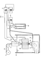
- FIG. 1 is a diagram showing a schematic configuration of an electric discharge machine 100 according to a first embodiment of the present invention.
- the electric discharge machining apparatus 100 applies a voltage between the wire electrode 10 and the workpiece 25 to generate an electric discharge in a gap between the wire electrode 10 and the workpiece 25 in the machining fluid, so that The workpiece 25 which is a hard alloy is processed.
- the workpiece 25 is a tungsten carbide-cobalt (WC-Co) alloy containing WC as a main component, mixed with cobalt (Co) as a binder, and sintered.
- WC-Co tungsten carbide-cobalt
- the electric discharge machine 100 has a wire bobbin 11 from which the linear wire electrode 10 is fed.
- the wire electrode 10 drawn out from the wire bobbin 11 is hooked on a pulley 12 and then passed through an upper guide portion 13 and a lower guide portion 14.
- the upper guide 13 and the lower guide 14 are guides for guiding the travel of the wire electrode 10.
- the wire electrode 10 is hung on a pulley 17 in the lower guide portion 14 and then wound up by a wire collection bobbin provided outside the lower guide portion 14. In FIG. 1, illustration of the wire collection bobbin is omitted.
- the workpiece 25 is placed on a stage arranged between the upper nozzle 15 of the upper guide 13 and the lower nozzle 16 of the lower guide 14 in the processing tank 19.
- the stage moves in a plane perpendicular to the traveling direction of the wire electrode 10 between the upper guide section 13 and the lower guide section 14. In FIG. 1, illustration of the stage is omitted.
- the processing tank 19 stores deionized water as a processing liquid.
- the liquid level of the processing liquid in the processing tank 19 reaches the upper guide portion 13.
- the lower end of the upper guide 13 including the upper nozzle 15 is immersed in the working fluid.
- the lower guide portion 14, the stage, and the workpiece 25 are sunk below the upper nozzle 15 in the processing liquid.
- a machining liquid is jetted toward the machining groove 26.
- FIG. 1 illustration of the configuration for jetting the working fluid is omitted.
- a machining groove 26 is formed in the workpiece 25 between the upper guide portion 13 and the lower guide portion 14 along the traveling direction of the wire electrode 10.
- the upper guide 13 is provided with a power supply 18 for connecting the wire electrode 10 and the processing power supply 21.
- the processing power supply 21 is connected to the power supply 18 and the workpiece 25, and supplies processing energy between the power supply 18 and the workpiece 25 in a pulsed manner.
- the electric discharge machine 100 has a gas supply device 22 which is an oxygen amount adjusting unit for adjusting the amount of oxygen contained in the machining fluid, and an on-off valve 23.
- the gas supply device 22 has a gas cylinder filled with oxygen gas.
- the gas supply device 22 supplies oxygen gas into the processing tank 19 by sending oxygen gas to the pipe 24.
- a nozzle 27 for discharging oxygen gas is provided at an end of the pipe 24 opposite to the gas supply device 22.
- the nozzle 27 is disposed below the wire electrode 10 running between the lower nozzle 16 and the pulley 17 in the lower guide portion 14.
- the on-off valve 23 provided in the pipe 24 switches between an open state for passing oxygen gas and a closed state for shutting off oxygen gas.
- the control device 20 controls the entire electric discharge machining device 100.
- the control device 20 controls the application of the pulse voltage by the processing power supply 21 and controls the supply of oxygen gas by the gas supply device 22 and the opening and closing of the on-off valve 23.
- FIG. 2 is a block diagram showing a functional configuration of the control device 20 included in the electric discharge machine 100 shown in FIG.
- the control device 20 includes a processing control unit 31 that is a functional unit that controls the processing of the workpiece 25, a gas supply control unit 32 that is a functional unit that controls the gas supply device 22 and the on-off valve 23, And a wire supply speed control unit 33 which is a function unit for controlling the supply speed.
- the wire supply speed control unit 33 controls the supply speed of the wire electrode 10 by controlling the operations of the wire bobbin 11 and the wire collection bobbin.
- the processing control unit 31 controls the relative position of the wire electrode 10 on the workpiece 25 by controlling the operation of the stage.
- the processing control unit 31 controls the rough processing as the first processing and the finishing processing as the second processing according to the processing program.
- Roughing is processing for cutting out a target shape from the workpiece 25 with the first dimensional accuracy.
- the finishing process is a process of cutting out a target shape from the workpiece 25 subjected to the rough processing with a second dimensional accuracy higher than the first dimensional accuracy.
- the electric discharge machine 100 performs the rough machining from the workpiece 25 in an initial state before machining to a rough intermediate shape in which the removal amount until the final shape is obtained is left.
- the first dimensional accuracy may be any dimensional accuracy that can provide a rough intermediate shape.
- Finishing is processing until obtaining the final shape after roughing.
- the second dimensional accuracy is the dimensional accuracy required to obtain the final shape.
- the finishing includes not only the final finishing for obtaining the final shape, but also the intermediate finishing performed between the roughing and the final finishing.
- the gas supply control unit 32 performs an operation of sending out oxygen gas from the gas supply device 22 and opening the on-off valve 23 at the time of roughing.
- the gas supply control unit 32 performs an operation of sending out oxygen gas from the gas supply device 22 and opening the on-off valve 23 at the time of roughing.
- bubbles of oxygen gas are generated from the nozzle 27.
- Oxygen gas bubbles are bubbles that are larger than microbubbles, which are bubbles having a diameter of about 1 ⁇ m to 50 ⁇ m, and are bubbles that can float more easily than microbubbles and can easily disappear at the liquid level. .
- the bubbles When the bubbles are released from the nozzle 27 in the lower guide portion 14, the bubbles rise along the wire electrode 10 due to buoyancy received from the working fluid. Bubbles coming out of the lower nozzle 16 float between the wire electrode 10 and the wall of the processing groove 26. Thereby, the gas supply device 22 and the on-off valve 23 supply oxygen to the working fluid in the gap between the wire electrode 10 and the workpiece 25.
- the gas supply control unit 32 performs an operation of stopping the supply of the oxygen gas to the gas supply device 22 and closing the on-off valve 23 at the time of finishing.
- the gas supply device 22 and the on-off valve 23 stop the release of bubbles from the nozzle 27.
- the gas supply device 22 and the on-off valve 23 supply oxygen gas to the gap between the wire electrode 10 and the workpiece 25 in rough machining, and supply the oxygen gas to the gap between the wire electrode 10 and the workpiece 25 in finish machining. Stop the supply of oxygen gas. In this way, the gas supply device 22 and the on-off valve 23 adjust the amount of oxygen contained in the working fluid in the gap between the wire electrode 10 and the workpiece 25 to be larger in the roughing than in the finishing. .
- the amount of oxygen is the amount of bubbles in the working fluid or the amount of oxygen dissolved in the working fluid.
- the electric discharge machine 100 decomposes WC into tungsten (W) and carbon (C) by causing discharge while supplying oxygen to the gap between the wire electrode 10 and the workpiece 25 during rough machining.
- the presence of oxygen causes a WC decomposition reaction represented by the following chemical reaction formula. WC ⁇ W + C 2W + 3O 2 ⁇ 2WO 3 C + O 2 ⁇ CO 2 ⁇
- the decomposition reaction of WC occurs at a temperature of 600 ° C. to 700 ° C., which is lower than the melting point of WC, approximately 2900 ° C. Since the decomposition of WC proceeds at a temperature closer to room temperature than the melting point, the processing by decomposition is more likely to proceed than the processing by melting. For this reason, in the electric discharge machining apparatus 100, in the rough machining, the machining by melting is added to the machining by melting, so that the machining speed can be improved. The electric discharge machining apparatus 100 can shorten the time required for machining the workpiece 25 by improving the machining speed in the rough machining.
- Electrical discharge machine 100 stops supply of oxygen to the gap between wire electrode 10 and workpiece 25 at the time of finish machining.
- the amount of oxygen contained in the working fluid is returned to the original amount before oxygen gas was supplied to the working fluid during rough machining. Since the bubbles released into the working fluid during the roughing can be easily eliminated as described above, it is possible to easily switch from a state in which bubbles exist to a state without bubbles. .
- the electric discharge machining device 100 performs the machining only by dissolving the WC without performing the machining by the decomposition of the WC by generating an electric discharge in a machining fluid having a smaller amount of oxygen than that in the rough machining.
- the electric discharge machining apparatus 100 can perform the machining while suppressing the deterioration of the machining surface by performing the machining only by dissolving the WC without performing the machining by the decomposition of the WC.
- the electric discharge machine 100 can obtain a high quality machined surface in the final shape by suppressing the deterioration of the machined surface in the finish machining.
- oil may be used as a machining fluid for electric discharge machining, but water can dissolve oxygen more easily than oil. Since the machining fluid used for machining the workpiece 25 is water, the electric discharge machining apparatus 100 can easily perform adjustment for increasing the amount of oxygen contained in the machining fluid in rough machining compared to finishing machining. .
- FIG. 3 is a flowchart showing a procedure of an electric discharge machining method performed by the electric discharge machine 100 shown in FIG.
- step S ⁇ b> 1 the electric discharge machine 100 starts supplying oxygen gas to the gap between the workpiece 25 and the wire electrode 10 by sending out oxygen gas from the gas supply device 22 and opening the on-off valve 23.
- step S2 the electric discharge machine 100 performs rough machining of the workpiece 25 according to a machining program.
- step S3 the electric discharge machining device 100 stops the supply of oxygen gas from the gas supply device 22 and closes the on-off valve 23, thereby stopping the supply of oxygen gas.
- step S4 the electric discharge machine 100 performs finish machining of the workpiece 25 according to the machining program. After finishing the finishing in step S4, the electric discharge machine 100 ends the operation shown in FIG.
- the function of the control device 20 of the electric discharge machine 100 is realized by a processing circuit.
- the processing circuit is dedicated hardware mounted on the control device 20 of the electric discharge machine 100.
- the processing circuit may be a processor that executes a program stored in a memory.
- the dedicated hardware processing circuit is a single circuit, a composite circuit, a programmed processor, a parallel programmed processor, an ASIC (Application Specific Integrated Circuit), an FPGA (Field-Programmable Gate Array), or a combination thereof. It is.
- the function of the control device 20 may be realized by a processor that executes a program stored in a memory.
- the processor and the memory are communicably connected to each other.
- the processor is a CPU (Central Processing Unit), a processing device, an arithmetic device, a microprocessor, a microcomputer, or a DSP (Digital Signal Processor).
- Each function of the processing control unit 31, the gas supply control unit 32, and the wire supply speed control unit 33 included in the control device 20 is realized by a processor, software, firmware, or a combination of software and firmware.
- Software or firmware is described as a program and stored in a memory.
- the memory is a non-volatile or volatile memory such as a RAM (Random Access Memory), a ROM (Read Only Memory), a flash memory, an EPROM (Erasable Programmable Read Only Memory), and an EEPROM (registered trademark) (Electrically Erasable Programmable Read-Only Memory).
- RAM Random Access Memory
- ROM Read Only Memory
- flash memory an EPROM (Erasable Programmable Read Only Memory)
- EEPROM registered trademark
- Built-in memory such as a semiconductor memory.
- a part of the function of the control device 20 may be realized by dedicated hardware, and the other part of the function of the control device 20 may be realized by software or firmware. As described above, the function of the control device 20 can be realized by hardware, software, firmware, or a combination thereof.
- the gas supplied to the gap between the wire electrode 10 and the workpiece 25 is not limited to oxygen gas, which is a pure substance, but may be any mixed gas containing oxygen.
- the gas supply device 22 may supply air. In this case, the gas supply device 22 adjusts the amount of oxygen contained in the working fluid by supplying air.
- the gas supply device 22 may be a pump that takes in air from around the electric discharge machining device 100 and sends out the taken-in air.
- FIG. 4 is a view showing a modification of the configuration for supplying bubbles in the electric discharge machine 100 shown in FIG.
- FIG. 4 shows a cross-sectional configuration of a lower guide portion 51 having a configuration according to a modification.
- the ventilation path 53 and the ventilation port 54 which are components for transporting the wire electrode 10 passed through the lower guide 51, are diverted to supply air in roughing.
- the lower guide portion 51 is provided with a traveling path 55 of the wire electrode 10 from the lower nozzle 16 to the end of the pulley 17.
- the end 52 of the traveling path 55 on the side of the lower nozzle 16 has a funnel shape in which the diameter decreases as going downward.
- the lower guide portion 51 is provided with a ventilation port 54 through which air passes, and a ventilation path 53 connecting the ventilation port 54 and the end portion 52.
- the electric discharge machine 100 sends air from the pump to the end 52 via the ventilation passage 53 in rough machining.
- the pressure of the air supplied to the end portion 52 is weaker than when the wire electrode 10 is transported.
- the electric discharge machine 100 supplies air to the gap between the wire electrode 10 and the workpiece 25 using the configuration for transporting the wire electrode 10 in the lower guide portion 51.
- the electric discharge machine 100 can adjust the amount of air contained in the machining fluid in the gap between the wire electrode 10 and the workpiece 25 to be larger in rough machining than in finish machining.
- the electric discharge machine 100 uses the air passage 53 and the air hole 54 for transporting the wire electrode 10 for supplying air in the rough machining, so that the configuration for supplying air in the rough machining is used.
- the number of parts can be reduced as compared with the case in which is provided separately.
- the electric discharge machining device 100 is not limited to a device for supplying oxygen to the gap between the wire electrode 10 and the workpiece 25 from below.
- the electric discharge machine 100 may supply air bubbles into the gap between the wire electrode 10 and the workpiece 25 from above.
- the electric discharge machine 100 may supply the air bubbles from above to the gap between the wire electrode 10 and the workpiece 25 by injecting air bubbles together with the machining liquid from the upper nozzle 15 of the upper guide section 13.
- the electric discharge machine 100 may eject the bubbles together with the machining liquid from the lower nozzle 16 of the lower guide portion 14.
- the electric discharge machine 100 may supply air bubbles to the gap between the wire electrode 10 and the workpiece 25 from both below and above in the rough machining.
- the electric discharge machine 100 supplies the air bubbles into the gap between the wire electrode 10 and the workpiece 25 from at least one of the lower side and the upper side, so that the amount of oxygen contained in the working fluid is made rougher than in the finish machining. Can be increased in processing.
- the electric discharge machining apparatus 100 performs adjustment by using the gas supply device 22 and the on-off valve 23 so that the amount of oxygen contained in the machining fluid is larger in the rough machining than in the finish machining.
- the electric discharge machine 100 promotes the decomposition of the cemented carbide by increasing the amount of oxygen in the rough machining, thereby improving the machining speed.
- the electric discharge machining apparatus 100 performs the processing by melting the cemented carbide instead of the decomposition of the cemented carbide by making the amount of oxygen smaller in the finishing machining than in the rough machining. In the finishing process, the electric discharge machining apparatus 100 can perform machining while suppressing deterioration in the quality of the machined surface. Accordingly, the electric discharge machining apparatus 100 has an effect that the machining time can be reduced and a high-quality machining surface can be obtained.
- FIG. FIG. 5 is a diagram illustrating a schematic configuration of the electric discharge machine 101 according to the second embodiment of the present invention.
- the electric discharge machining apparatus 101 includes a first tank 61 and a second tank 62 for supplying machining fluids having different amounts of oxygen.
- the same portions as those in the first embodiment are denoted by the same reference numerals, and a configuration different from the first embodiment will be mainly described.
- the first tank 61 is provided with a bubble generator for increasing the dissolved oxygen contained in the working fluid.
- the amount of dissolved oxygen in the first processing liquid which is the processing liquid stored in the first tank 61, is greater than that in a normal processing liquid due to the operation of the bubble generator.
- a second working fluid which is a normal working fluid in which the dissolved oxygen is not increased, is stored.
- the amount of oxygen contained in the first working fluid is made larger than that of the second working fluid stored in the second tank 62.
- the amount of oxygen is the amount of dissolved oxygen in the working fluid.
- the electric discharge machine 101 includes pumps 63 and 64, which are oxygen amount adjusting units, and on-off valves 65, 66, 67 and 68.
- the pump 63 sends out the first processing liquid stored in the first tank 61 to the pipe 71.
- the pipe 71 is branched into two.
- the on-off valve 65 is provided on one of two branched pipes 71.
- the on-off valve 66 is provided on the other of the two branched pipes 71.
- the pump 64 sends out the second processing liquid stored in the second tank 62 to the pipe 72.
- the pipe 72 is branched into two.
- the on-off valve 67 is provided on one of the two branched pipes 72.
- the on-off valve 68 is provided on the other of the two branched pipes 72.
- the pipe 71 provided with the on-off valve 65 and the pipe 72 provided with the on-off valve 67 are merged into one pipe 60.
- the pipe 60 is connected to the upper guide section 13.
- the pipe 71 provided with the on-off valve 66 and the pipe 72 provided with the on-off valve 68 are merged into one pipe 70.
- the pipe 70 is connected to the lower guide section 14.
- the first processing liquid and the second processing liquid that have passed through the pipe 60 are supplied to the upper guide portion 13.
- the first processing liquid and the second processing liquid that have passed through the pipe 70 are supplied to the lower guide portion 14.
- the gas supply control unit 32 shown in FIG. 2 controls the operation of the pumps 63 and 64 and the opening and closing of the on-off valves 65, 66, 67 and 68.
- the gas supply control unit 32 operates the pump 63 and stops the pump 64.
- the gas supply control unit 32 performs an operation of opening the on-off valves 65 and 66 and performs an operation of closing the on-off valves 67 and 68.
- the opening / closing valve 65 is opened together with the operation of the pump 63, the first processing liquid supplied to the upper guide unit 13 through the pipe 60 is jetted from the upper nozzle 15 of the upper guide unit 13.
- the opening / closing valve 66 is opened together with the operation of the pump 63, the first processing liquid supplied to the lower guide portion 14 through the pipe 70 is jetted from the lower nozzle 16 of the lower guide portion 14.
- the gas supply control unit 32 stops the pump 63 and operates the pump 64. Further, the gas supply control unit 32 performs an operation of closing the on-off valves 65 and 66 and an operation of opening the on-off valves 67 and 68.
- the on-off valve 67 is opened together with the operation of the pump 64, the second processing liquid supplied to the upper guide unit 13 through the pipe 60 is jetted from the upper nozzle 15 of the upper guide unit 13.
- the on-off valve 68 is opened together with the operation of the pump 64, the second processing liquid supplied to the lower guide unit 14 through the pipe 70 is jetted from the lower nozzle 16 of the lower guide unit 14.
- the pumps 63 and 64 and the on-off valves 65, 66, 67 and 68 supply the first working fluid to the gap between the wire electrode 10 and the workpiece 25 in rough machining, and the wire electrode 10 and the workpiece in finish machining.
- the second working fluid is supplied to the gap with the object 25.
- the pumps 63 and 64 and the on-off valves 65, 66, 67 and 68 reduce the amount of oxygen gas contained in the working fluid in the gap between the wire electrode 10 and the workpiece 25 in rough machining compared to finish machining. Make adjustments to make more.
- FIG. 6 is a flowchart showing the procedure of the electric discharge machining method performed by the electric discharge machine 101 shown in FIG.
- step S11 the electric discharge machine 101 starts supplying the first machining liquid to the gap between the workpiece 25 and the wire electrode 10 by operating the pump 63 and opening the on-off valves 65 and 66.
- step S12 the electric discharge machine 101 performs rough machining of the workpiece 25 according to the machining program.
- step S13 the electric discharge machining apparatus 101 stops the supply of the first machining fluid by stopping the operation of the pump 63 and closing the on-off valves 65 and 66. Further, in step S13, the electric discharge machining apparatus 101 starts supplying the second machining fluid to the gap between the workpiece 25 and the wire electrode 10 by operating the pump 64 and opening the on-off valves 67 and 68. I do. In step S ⁇ b> 14, the electric discharge machine 101 performs finish machining of the workpiece 25 according to a machining program.
- step S14 the electric discharge machining apparatus 101 stops the supply of the second machining fluid by stopping the operation of the pump 64 and closing the on-off valves 67 and 68 in step S15. Thereby, the electric discharge machine 101 ends the operation shown in FIG.
- the electric discharge machining device 101 is not limited to the one that supplies the first machining fluid and the second machining fluid from both the upper guide portion 13 and the lower guide portion 14.
- the electric discharge machining device 101 may supply the first machining fluid and the second machining fluid from one of the upper guide portion 13 and the lower guide portion 14.
- the electric discharge machining device 101 supplies the first machining fluid and the second machining fluid from at least one of the upper guide portion 13 and the lower guide portion 14 to reduce the amount of oxygen contained in the machining fluid. More can be made in roughing than in finishing.
- the electric discharge machining apparatus 101 supplies the first machining fluid in the rough machining and supplies the second machining fluid in the finishing machining, thereby providing a gap between the wire electrode 10 and the workpiece 25. Is adjusted so that the amount of oxygen contained in the working fluid in the roughing is larger than that in the finishing. Accordingly, the electric discharge machine 101 has an effect that the machining time can be reduced and a high quality machined surface can be obtained.
- FIG. 7 is a diagram illustrating a schematic configuration of the electric discharge machine 102 according to the third embodiment of the present invention.
- the electric discharge machining device 102 includes a cooling device 82 that increases the cooling strength and cools the machining fluid in rough machining rather than finish machining.
- the same portions as those in the first and second embodiments are denoted by the same reference numerals, and a configuration different from the first and second embodiments will be mainly described.
- the electric discharge machine 102 includes a tank 80 for storing a machining fluid.
- the tank 80 stores the working fluid before being passed through the cooling device 82.
- the pump 81 sends the processing liquid stored in the tank 80 to the pipe 73 via the cooling device 82.
- the cooling device 82 cools the working fluid from the tank 80.
- the pipe 73 is branched into two pipes 60 and 70.
- the pipe 60 is connected to the upper guide unit 13.
- the pipe 70 is connected to the lower guide section 14.
- the working fluid that has passed through the pipe 60 is supplied to the upper guide 13.
- the working fluid that has passed through the pipe 70 is supplied to the lower guide portion 14.
- the cooling device 82 which is an oxygen amount adjusting unit, cools the working fluid in the rough machining and stops cooling the machining fluid in the finishing machining, thereby lowering the temperature of the machining fluid in the rough machining compared to the finishing machining.
- the cooling device 82 adjusts the amount of oxygen contained in the working fluid to be larger in the roughing than in the finishing by lowering the temperature of the working fluid in the roughing than in the finishing.
- the cooling device 82 increases the cooling strength in the roughing rather than the finishing and cools the working fluid, so that the cooling in the roughing is more than the finishing. Lower the temperature of the working fluid.
- the amount of oxygen is the amount of dissolved oxygen in the working fluid.
- the gas supply control unit 32 shown in FIG. 2 controls the operation of the pump 81 and the operation of the cooling device 82.
- the gas supply control unit 32 causes the cooling device 82 to perform cooling in the roughing process and stops the cooling by the cooling device 82 in the finishing process.
- the gas supply control unit 32 performs control to make the cooling intensity of the cooling device 82 in the roughing process stronger than the cooling intensity of the cooling device 82 in the finishing process.
- FIG. 8 is a flowchart showing a procedure of an electric discharge machining method performed by the electric discharge machine 102 shown in FIG.
- the electric discharge machining device 102 starts supplying the machining fluid cooled by the cooling device 82.
- the electric discharge machine 102 supplies a machining fluid to a gap between the workpiece 25 and the wire electrode 10.
- the electric discharge machine 102 performs rough machining of the workpiece 25 according to the machining program.
- step S22 After finishing the rough machining in step S22, the electric discharge machine 102 weakens the intensity of cooling by the cooling device 82.
- step S23 the electric discharge machine 102 starts supplying the cooled machining fluid with reduced strength.
- the electric discharge machine 102 supplies a machining fluid to a gap between the workpiece 25 and the wire electrode 10.
- step S24 the electric discharge machine 102 performs finish machining of the workpiece 25 according to the machining program.
- the electric discharge machine 102 stops cooling the machining fluid by the cooling device 82 and stops supplying the machining fluid by the pump 81 in step S25.
- the cooling device 82 may stop cooling the working fluid in the above-described step S23.
- the electric discharge machine 102 is not limited to the one that supplies the machining fluid from both the upper guide section 13 and the lower guide section 14.
- the electric discharge machine 102 may supply a machining fluid from one of the upper guide section 13 and the lower guide section 14.
- the electric discharge machine 102 finishes the amount of oxygen contained in the machining fluid by supplying the machining fluid from at least one of the upper guide section 13 and the lower guide section 14 and changing the temperature of the machining fluid. It can be increased more in rough machining than in machining.
- the electric discharge machining apparatus 102 reduces the amount of oxygen contained in the machining fluid in the gap between the wire electrode 10 and the workpiece 25 by lowering the temperature of the machining fluid in rough machining than in finish machining. Make adjustments to make more in roughing than in finishing.
- the electric discharge machine 102 has an effect that a machining time can be reduced and a high quality machined surface can be obtained.
Landscapes
- Chemical & Material Sciences (AREA)
- Chemical Kinetics & Catalysis (AREA)
- Electrochemistry (AREA)
- Engineering & Computer Science (AREA)
- Mechanical Engineering (AREA)
- Electrical Discharge Machining, Electrochemical Machining, And Combined Machining (AREA)
Abstract
放電加工装置(100)は、ワイヤ電極(10)と被加工物(25)との間に電圧を印加して、加工液中において、ワイヤ電極(10)と被加工物(25)との間隙に放電を生じさせることによって被加工物(25)を加工する。放電加工装置(100)は、第1の寸法精度で被加工物(25)から目標形状を切り出す第1の加工と、第1の加工が施された被加工物(25)から第1の寸法精度よりも高い第2の寸法精度で目標形状を切り出す第2の加工とを制御する加工制御部と、加工液に含まれる酸素の量を第2の加工よりも第1の加工において多くさせる調整を行う酸素量調整部と、を備える。
Description
本発明は、被加工物の放電加工を行う放電加工装置および放電加工方法に関する。
ワイヤ電極と被加工物との間の放電によって発生させた熱を利用して被加工物を溶融し、被加工物を加工する放電加工装置が知られている。特許文献1には、酸素を含む微細な気泡を加工液に含ませて加工を行う放電加工装置が開示されている。特許文献1の技術によると、放電加工装置は、放電による熱に酸化熱が加わることによって加工液の気化爆発を大きくさせて、加工速度を向上可能とする。
従来、放電加工装置は、超硬合金であるタングステンカーバイド(WC)が主成分である被加工物の加工に用いられることがある。放電加工の対象とされる材料の中ではWCの融点はおよそ2900℃ときわめて高いことから、超硬合金の放電加工において、放電を受けることによって溶融した部分のうち被加工物から除去される割合は10%未満にとどまるという研究報告がある。超硬合金の放電加工において、溶融した部分のほとんどが再び固化して被加工物に残存することから、放電加工装置は、超硬合金の加工に時間を要することになる。
超硬合金の加工において、上記の特許文献1の技術と同様に加工液に微細な気泡を含ませた場合、酸素の存在により、WCの融点よりも低い温度にてWCの分解反応が起こる。融点に比べて常温に近い温度でWCの分解は進行するため、溶融による加工よりも分解による加工のほうが進行し易い。このため、溶融による加工に分解による加工が加わることによって、加工速度の向上が可能となる。放電加工装置は、加工速度の向上によって、超硬合金の加工に要する時間を短くすることができる。しかしながら、分解による加工は被加工物の表面を崩壊させながら進行することから、分解による加工によって、高品質な加工面を得ることが困難となる。このため、被加工物の加工に特許文献1の技術が適用された場合に、加工時間の短縮が可能となる一方で、高品質な加工面を得ることが困難となる場合があるという問題があった。
本発明は、上記に鑑みてなされたものであって、加工時間を短縮可能とするとともに高品質な加工面を得ることができる放電加工装置を得ることを目的とする。
上述した課題を解決し、目的を達成するために、本発明にかかる放電加工装置は、ワイヤ電極と被加工物との間に電圧を印加して、加工液中において、ワイヤ電極と被加工物との間隙に放電を生じさせることによって被加工物を加工する。本発明にかかる放電加工装置は、第1の寸法精度で被加工物から目標形状を切り出す第1の加工と、第1の加工が施された被加工物から第1の寸法精度よりも高い第2の寸法精度で目標形状を切り出す第2の加工とを制御する加工制御部と、加工液に含まれる酸素の量を第2の加工よりも第1の加工において多くさせる調整を行う酸素量調整部と、を備える。
本発明にかかる放電加工装置は、加工時間を短縮可能とするとともに高品質な加工面を得ることができるという効果を奏する。
以下に、本発明の実施の形態にかかる放電加工装置および放電加工方法を図面に基づいて詳細に説明する。なお、この実施の形態によりこの発明が限定されるものではない。
実施の形態1.
図1は、本発明の実施の形態1にかかる放電加工装置100の概略構成を示す図である。放電加工装置100は、ワイヤ電極10と被加工物25との間に電圧を印加して、加工液中において、ワイヤ電極10と被加工物25とが向き合う間隙に放電を生じさせることによって、超硬合金である被加工物25を加工する。被加工物25は、WCが主成分であって、結合剤であるコバルト(Co)と混合して焼結した、タングステンカーバイド-コバルト(WC-Co)系合金である。
図1は、本発明の実施の形態1にかかる放電加工装置100の概略構成を示す図である。放電加工装置100は、ワイヤ電極10と被加工物25との間に電圧を印加して、加工液中において、ワイヤ電極10と被加工物25とが向き合う間隙に放電を生じさせることによって、超硬合金である被加工物25を加工する。被加工物25は、WCが主成分であって、結合剤であるコバルト(Co)と混合して焼結した、タングステンカーバイド-コバルト(WC-Co)系合金である。
放電加工装置100は、線状のワイヤ電極10が繰り出されるワイヤボビン11を有する。ワイヤボビン11から繰り出されたワイヤ電極10は、プーリ12に掛けられてから上ガイド部13と下ガイド部14とへ通される。上ガイド部13と下ガイド部14は、ワイヤ電極10の走行をガイドするガイド部である。ワイヤ電極10は、下ガイド部14内のプーリ17に掛けられてから、下ガイド部14の外に設けられているワイヤ回収ボビンにて巻き取られる。図1では、ワイヤ回収ボビンの図示を省略している。
被加工物25は、加工槽19内において、上ガイド部13の上ノズル15と下ガイド部14の下ノズル16との間に配置されるステージに置かれる。ステージは、上ガイド部13と下ガイド部14との間におけるワイヤ電極10の走行方向に直交する面内において移動する。図1では、ステージの図示を省略している。加工槽19には、加工液である脱イオン水が溜められる。加工槽19における加工液の液面は、上ガイド部13に到達している。上ガイド部13のうち上ノズル15を含む下端部は、加工液に浸けられている。加工槽19において、下ガイド部14とステージと被加工物25とは、加工液中にて上ノズル15よりも下方にて沈められている。
上ガイド部13の上ノズル15と下ガイド部14の下ノズル16との少なくとも一方からは、加工溝26へ向けて加工液が噴射される。図1では、加工液の噴射のための構成の図示を省略している。被加工物25への放電加工によって、被加工物25には、上ガイド部13と下ガイド部14との間におけるワイヤ電極10の走行方向に沿った加工溝26が形成される。
上ガイド部13には、ワイヤ電極10と加工電源21とを接続する給電子18が設けられている。加工電源21は、給電子18と被加工物25とに接続され、給電子18と被加工物25との間へパルス状に加工エネルギーを供給する。
放電加工装置100は、加工液に含まれる酸素の量を調整する酸素量調整部である気体供給装置22と開閉弁23とを有する。気体供給装置22は、酸素ガスが充填されたガスボンベを有する。気体供給装置22は、配管24へ酸素ガスを送り出すことによって、加工槽19の内部へ酸素ガスを供給する。配管24のうち気体供給装置22とは逆側の端には、酸素ガスを放出させるノズル27が設けられている。ノズル27は、下ガイド部14内において下ノズル16とプーリ17との間を走行するワイヤ電極10の下方に配置される。配管24に設けられた開閉弁23は、酸素ガスを通過させる開状態と酸素ガスを遮断する閉状態との切り換えを行う。
制御装置20は、放電加工装置100の全体を制御する。制御装置20は、加工電源21によるパルス電圧の印加を制御するとともに、気体供給装置22による酸素ガスの供給と、開閉弁23の開閉とを制御する。
図2は、図1に示す放電加工装置100が有する制御装置20の機能構成を示すブロック図である。制御装置20は、被加工物25の加工を制御する機能部である加工制御部31と、気体供給装置22および開閉弁23を制御する機能部である気体供給制御部32と、ワイヤ電極10の供給速度を制御する機能部であるワイヤ供給速度制御部33とを有する。
ワイヤ供給速度制御部33は、ワイヤボビン11とワイヤ回収ボビンとの動作の制御によって、ワイヤ電極10の供給速度を制御する。加工制御部31は、ステージの動作の制御によって、被加工物25におけるワイヤ電極10の相対位置を制御する。加工制御部31は、加工プログラムにしたがい、第1の加工である荒加工と第2の加工である仕上げ加工とを制御する。荒加工は、第1の寸法精度で被加工物25から目標形状を切り出す加工である。仕上げ加工は、荒加工が施された被加工物25から、第1の寸法精度よりも高い第2の寸法精度で目標形状を切り出す加工である。
放電加工装置100は、荒加工によって、加工が施される前の初期状態における被加工物25から、最終形状が得られるまでの除去分が残された大まかな中間形状までの切削を行う。第1の寸法精度は、大まかな中間形状が得られる寸法精度であれば良い。仕上げ加工は、荒加工よりも後における最終形状を得るまでの加工である。第2の寸法精度は、最終形状を得るために求められる寸法精度である。仕上げ加工には、最終形状を得るための最終仕上げ加工のほか、荒加工と最終仕上げ加工との間に実施される中仕上げ加工も含まれる。
気体供給制御部32は、荒加工のときに、気体供給装置22から酸素ガスを送り出させるとともに開閉弁23を開く操作を行う。気体供給装置22から酸素ガスを送り出すとともに開閉弁23を開くことによって、ノズル27からは酸素ガスの気泡が発生する。酸素ガスの気泡は、1μmから50μm程度の直径の泡であるマイクロバブルよりも大きな泡であって、マイクロバブルに比べて容易に浮上可能であるとともに液面にて容易に消滅可能な泡である。
気泡は、ノズル27から下ガイド部14内にて放出されると、加工液から受ける浮力によってワイヤ電極10に沿って上昇する。下ノズル16から出た気泡は、ワイヤ電極10と加工溝26の壁との間を浮上する。これにより、気体供給装置22と開閉弁23とは、ワイヤ電極10と被加工物25との間隙における加工液へ酸素を供給する。
気体供給制御部32は、仕上げ加工のときに、気体供給装置22に酸素ガスの供給を停止させるとともに開閉弁23を閉じる操作を行う。気体供給装置22と開閉弁23とは、ノズル27からの気泡の放出を停止させる。
気体供給装置22と開閉弁23とは、荒加工では、ワイヤ電極10と被加工物25との間隙へ酸素ガスを供給し、仕上げ加工では、ワイヤ電極10と被加工物25との間隙への酸素ガスの供給を停止する。このようにして、気体供給装置22と開閉弁23とは、ワイヤ電極10と被加工物25との間隙において加工液に含まれる酸素の量を、仕上げ加工よりも荒加工において多くさせる調整を行う。実施の形態1において、酸素の量とは、加工液中の気泡の量、または加工液中に溶存する酸素の量とする。
放電加工装置100は、荒加工のとき、ワイヤ電極10と被加工物25との間隙へ酸素を供給しながら放電を生じさせることによって、WCをタングステン(W)と炭素(C)とへ分解させる。酸素の存在により、次に示す化学反応式によって表されるWCの分解反応が起こる。
WC→W+C
2W+3O2→2WO3
C+O2→CO2↑
WC→W+C
2W+3O2→2WO3
C+O2→CO2↑
WCの分解反応は、WCの融点であるおよそ2900℃よりも低い温度である600℃から700℃において起こる。融点に比べて常温に近い温度でWCの分解は進行するため、溶融による加工よりも分解による加工のほうが進行し易い。このため、放電加工装置100は、荒加工において、溶融による加工に分解による加工が加わることによって、加工速度の向上が可能となる。放電加工装置100は、荒加工での加工速度の向上によって、被加工物25の加工に要する時間を短くすることができる。
放電加工装置100は、仕上げ加工のとき、ワイヤ電極10と被加工物25との間隙への酸素の供給を停止させる。加工液に含まれる酸素の量は、荒加工の際に加工液へ酸素ガスが供給されるよりも前の元の量に戻される。荒加工のときに加工液中へ放出された気泡は、上述するように容易に消滅可能であることから、気泡を存在させた状況から、気泡が無い状況への切り換えを容易に行うことができる。
放電加工装置100は、仕上げ加工では、荒加工のときよりも酸素の量が少ない加工液中にて放電を生じさせることによって、WCの分解による加工を行わずWCの溶解のみによる加工を行う。放電加工装置100は、WCの分解による加工を行わずWCの溶解のみによる加工を行うことで、加工面の品質悪化を抑制しながら加工を行うことができる。放電加工装置100は、仕上げ加工での加工面の品質悪化の抑制により、最終形状において高品質な加工面を得ることができる。
放電加工の加工液には水以外に油が使用されることがあるが、水は油に比べて酸素を容易に溶存させ得る。被加工物25の加工に用いられる加工液が水であることにより、放電加工装置100は、加工液に含まれる酸素の量を仕上げ加工よりも荒加工において多くさせる調整を容易に行うことができる。
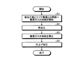
図3は、図1に示す放電加工装置100が行う放電加工方法の手順を示すフローチャートである。ステップS1では、放電加工装置100は、気体供給装置22から酸素ガスを送り出すとともに開閉弁23を開くことによって、被加工物25とワイヤ電極10との間隙へ酸素ガスの供給を開始する。ステップS2では、放電加工装置100は、加工プログラムにしたがって、被加工物25の荒加工を行う。
放電加工装置100は、ステップS2の荒加工を終えると、ステップS3において、気体供給装置22からの酸素ガスの送り出しを停止するとともに開閉弁23を閉じることによって、酸素ガスの供給を停止する。ステップS4では、放電加工装置100は、加工プログラムにしたがって、被加工物25の仕上げ加工を行う。放電加工装置100は、ステップS4の仕上げ加工を終えると、図3に示す動作を終了する。
放電加工装置100が有する制御装置20の機能は、処理回路により実現される。処理回路は、放電加工装置100の制御装置20に搭載される専用のハードウェアである。処理回路は、メモリに格納されるプログラムを実行するプロセッサであっても良い。
専用のハードウェアである処理回路は、単一回路、複合回路、プログラム化されたプロセッサ、並列プログラム化したプロセッサ、ASIC(Application Specific Integrated Circuit)、FPGA(Field-Programmable Gate Array)、又はこれらの組み合わせである。
制御装置20の機能は、メモリに格納されるプログラムを実行するプロセッサによって実現されても良い。プロセッサおよびメモリは、相互に通信可能に接続される。プロセッサは、CPU(Central Processing Unit)、処理装置、演算装置、マイクロプロセッサ、マイクロコンピュータ、又はDSP(Digital Signal Processor)である。制御装置20が有する加工制御部31と気体供給制御部32とワイヤ供給速度制御部33との各機能は、プロセッサと、ソフトウェア、ファームウェア、又はソフトウェアとファームウェアとの組み合わせによって実現される。ソフトウェア又はファームウェアは、プログラムとして記述され、メモリに格納される。メモリは、RAM(Random Access Memory)、ROM(Read Only Memory)、フラッシュメモリ、EPROM(Erasable Programmable Read Only Memory)、EEPROM(登録商標)(Electrically Erasable Programmable Read-Only Memory)等の不揮発性もしくは揮発性の半導体メモリ等の内蔵メモリである。
制御装置20の機能の一部が専用のハードウェアにより実現され、制御装置20の機能のその他の部分がソフトウェアあるいはファームウェアにより実現されても良い。このように、制御装置20の機能は、ハードウェア、ソフトウェア、ファームウェア、又はこれらの組み合わせによって実現することができる。
ワイヤ電極10と被加工物25との間隙へ供給される気体は、純物質である酸素ガスに限られず、酸素を含む混合気体であれば良い。気体供給装置22は、空気を供給しても良い。この場合、気体供給装置22は、空気を供給することによって、加工液に含まれる酸素の量を調整する。気体供給装置22は、放電加工装置100の周囲から空気を取り込み、取り込まれた空気を送り出すポンプであっても良い。
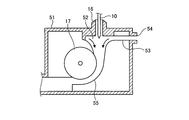
下ガイド部14へ気泡を供給するための構成は、適宜変更しても良い。図4は、図1に示す放電加工装置100における気泡の供給のための構成の変形例を示す図である。図4には、変形例にかかる構成を備える下ガイド部51の断面構成を示している。図4に示す変形例では、下ガイド部51に通されるワイヤ電極10の搬送のための構成である通気路53と通気口54とを、荒加工における空気の供給に流用する。
下ガイド部51には、下ノズル16からプーリ17の先へ向かうワイヤ電極10の走行路55が設けられている。走行路55のうち下ノズル16側の端部52は、下方へ向かうにしたがい直径が狭くなる漏斗形状をなしている。下ガイド部51には、空気が通る通気口54と、通気口54と端部52とをつなぐ通気路53とが設けられている。
加工の準備において、ワイヤボビン11から繰り出されたワイヤ電極10を下ガイド部51へ通す際に、通気口54に接続された気体供給装置22から通気路53を経て端部52へ空気が送られる。端部52へ空気が送られることにより、端部52から走行路55の先のほうへ加工液が押し出されて、走行路55の先のほうへ向かう加工液の流れが発生する。加工液の流れに乗って、ワイヤ電極10が走行路55の先のほうへ搬送されることによって、下ガイド部51にワイヤ電極10が通される。ワイヤ電極10を搬送させる場合において、端部52へ供給される空気の圧力は、走行路55の先のほうへ空気とともに加工液を進行させ得る圧力に調整される。
放電加工装置100は、荒加工において、ポンプから通気路53を経て端部52へ空気を送る。荒加工の場合において、端部52へ供給される空気の圧力は、ワイヤ電極10を搬送させる場合よりも弱められる。空気の圧力が弱められることで、通気路53から端部52へ放出された気泡の多くは、浮力によって下ノズル16のほうへ上昇する。これにより、放電加工装置100は、下ガイド部51におけるワイヤ電極10の搬送のための構成を用いて、ワイヤ電極10と被加工物25との間隙へ空気を供給する。このように、放電加工装置100は、ワイヤ電極10と被加工物25との間隙において加工液に含まれる空気の量を、仕上げ加工よりも荒加工において多くさせる調整を行うことができる。本変形例によると、放電加工装置100は、ワイヤ電極10の搬送のための通気路53と通気口54とを荒加工における空気の供給に利用するため、荒加工における空気の供給のための構成を別途設ける場合と比べて、部品点数を少なくすることができる。
放電加工装置100は、ワイヤ電極10と被加工物25との間隙へ下方から酸素を供給するものに限られない。放電加工装置100は、ワイヤ電極10と被加工物25との間隙へ上方から気泡を供給しても良い。放電加工装置100は、上ガイド部13の上ノズル15から加工液とともに気泡を噴射させることによって、ワイヤ電極10と被加工物25との間隙へ上方から気泡を供給しても良い。放電加工装置100は、下方からの気泡の供給のために、下ガイド部14の下ノズル16から加工液とともに気泡を噴射させても良い。放電加工装置100は、荒加工において、ワイヤ電極10と被加工物25との間隙へ下方と上方との双方から気泡を供給しても良い。放電加工装置100は、ワイヤ電極10と被加工物25との間隙へ下方と上方とのうちの少なくとも一方から気泡を供給することにより、加工液に含まれる酸素の量を、仕上げ加工よりも荒加工において多くさせることができる。
実施の形態1によると、放電加工装置100は、気体供給装置22と開閉弁23とによって、加工液に含まれる酸素の量を仕上げ加工よりも荒加工において多くさせる調整を行う。放電加工装置100は、荒加工では酸素の量を多くさせることで超硬合金の分解を促して、加工速度を向上させる。放電加工装置100は、仕上げ加工では荒加工のときよりも酸素の量を少なくさせることで超硬合金の分解に代えて超硬合金の溶融による加工を行う。放電加工装置100は、仕上げ加工では、加工面の品質悪化を抑制しながら加工を行うことができる。これにより、放電加工装置100は、加工時間を短縮可能とするとともに高品質な加工面を得ることができるという効果を奏する。
実施の形態2.
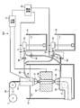
図5は、本発明の実施の形態2にかかる放電加工装置101の概略構成を示す図である。放電加工装置101は、酸素の量が互いに異なる加工液を供給するための第1のタンク61と第2のタンク62とを備える。実施の形態2では、実施の形態1と同一の部分には同一の符号を付し、実施の形態1とは異なる構成について主に説明する。
図5は、本発明の実施の形態2にかかる放電加工装置101の概略構成を示す図である。放電加工装置101は、酸素の量が互いに異なる加工液を供給するための第1のタンク61と第2のタンク62とを備える。実施の形態2では、実施の形態1と同一の部分には同一の符号を付し、実施の形態1とは異なる構成について主に説明する。
第1のタンク61には、加工液に含まれる溶存酸素を増加させるためのバブル発生装置が設けられている。第1のタンク61に貯留される加工液である第1の加工液は、バブル発生装置の作動によって、通常の加工液よりも溶存酸素量が増加している。第2のタンク62には、溶存酸素の増加が行われない通常の加工液である第2の加工液が貯留される。第1の加工液に含まれる酸素の量は、第2のタンク62に貯留される第2の加工液よりも多くされる。実施の形態2において、酸素の量とは、加工液中の溶存酸素量とする。
放電加工装置101は、酸素量調整部であるポンプ63,64と開閉弁65,66,67,68とを備える。ポンプ63は、第1のタンク61に貯留されている第1の加工液を配管71へ送り出す。配管71は2つに分岐されている。開閉弁65は、2つに分岐された配管71のうちの一方に設けられている。開閉弁66は、2つに分岐された配管71のうちの他方に設けられている。ポンプ64は、第2のタンク62に貯留されている第2の加工液を配管72へ送り出す。配管72は2つに分岐されている。開閉弁67は、2つに分岐された配管72のうちの一方に設けられている。開閉弁68は、2つに分岐された配管72のうちの他方に設けられている。
開閉弁65が設けられている配管71と、開閉弁67が設けられている配管72とは、互いに1つの配管60に合流される。配管60は、上ガイド部13に接続されている。開閉弁66が設けられている配管71と、開閉弁68が設けられている配管72とは、互いに1つの配管70に合流される。配管70は、下ガイド部14に接続されている。上ガイド部13には、配管60を通った第1の加工液と第2の加工液とが供給される。下ガイド部14には、配管70を通った第1の加工液と第2の加工液とが供給される。
図2に示す気体供給制御部32は、ポンプ63,64の動作と開閉弁65,66,67,68の開閉とを制御する。荒加工のときに、気体供給制御部32は、ポンプ63を動作させるとともにポンプ64を停止させる。また、気体供給制御部32は、開閉弁65,66を開く操作を行うとともに、開閉弁67,68を閉じる操作を行う。ポンプ63の動作とともに開閉弁65が開かれることにより、上ガイド部13の上ノズル15からは、配管60を通して上ガイド部13へ供給された第1の加工液が噴射される。ポンプ63の動作とともに開閉弁66が開かれることにより、下ガイド部14の下ノズル16からは、配管70を通して下ガイド部14へ供給された第1の加工液が噴射される。
仕上げ加工のときに、気体供給制御部32は、ポンプ63を停止させるとともにポンプ64を動作させる。また、気体供給制御部32は、開閉弁65,66を閉じる操作を行うとともに、開閉弁67,68を開く操作を行う。ポンプ64の動作とともに開閉弁67が開かれることにより、上ガイド部13の上ノズル15からは、配管60を通して上ガイド部13へ供給された第2の加工液が噴射される。ポンプ64の動作とともに開閉弁68が開かれることにより、下ガイド部14の下ノズル16からは、配管70を通して下ガイド部14へ供給された第2の加工液が噴射される。
ポンプ63,64と開閉弁65,66,67,68とは、荒加工ではワイヤ電極10と被加工物25との間隙へ第1の加工液を供給し、仕上げ加工ではワイヤ電極10と被加工物25との間隙へ第2の加工液を供給する。これにより、ポンプ63,64と開閉弁65,66,67,68とは、ワイヤ電極10と被加工物25との間隙において加工液に含まれる酸素ガスの量を、仕上げ加工よりも荒加工において多くさせる調整を行う。
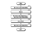
図6は、図5に示す放電加工装置101が行う放電加工方法の手順を示すフローチャートである。ステップS11では、放電加工装置101は、ポンプ63を動作させるとともに開閉弁65,66を開くことにより、被加工物25とワイヤ電極10との間隙への第1の加工液の供給を開始する。ステップS12では、放電加工装置101は、加工プログラムにしたがって、被加工物25の荒加工を行う。
放電加工装置101は、ステップS12の荒加工を終えると、ステップS13において、ポンプ63の動作を停止させるとともに開閉弁65,66を閉じることにより、第1の加工液の供給を停止する。また、ステップS13において、放電加工装置101は、ポンプ64を動作させるとともに開閉弁67,68を開くことにより、被加工物25とワイヤ電極10との間隙への第2の加工液の供給を開始する。ステップS14では、放電加工装置101は、加工プログラムにしたがって、被加工物25の仕上げ加工を行う。
放電加工装置101は、ステップS14の仕上げ加工を終えると、ステップS15において、ポンプ64の動作を停止させるとともに開閉弁67,68を閉じることにより、第2の加工液の供給を停止する。これにより、放電加工装置101は、図6に示す動作を終了する。
放電加工装置101は、上ガイド部13と下ガイド部14との双方から第1の加工液と第2の加工液とを供給するものに限られない。放電加工装置101は、上ガイド部13と下ガイド部14との一方から第1の加工液と第2の加工液とを供給するものであっても良い。放電加工装置101は、上ガイド部13と下ガイド部14とのうちの少なくとも一方から第1の加工液と第2の加工液とを供給することにより、加工液に含まれる酸素の量を、仕上げ加工よりも荒加工において多くさせることができる。
実施の形態2によると、放電加工装置101は、荒加工において第1の加工液を供給し、仕上げ加工において第2の加工液を供給することによって、ワイヤ電極10と被加工物25との間隙における加工液に含まれる酸素の量を仕上げ加工よりも荒加工において多くさせる調整を行う。これにより、放電加工装置101は、加工時間を短縮可能とするとともに高品質な加工面を得ることができるという効果を奏する。
実施の形態3.
図7は、本発明の実施の形態3にかかる放電加工装置102の概略構成を示す図である。放電加工装置102は、仕上げ加工よりも荒加工において冷却強度を上げて加工液を冷却する冷却装置82を備える。実施の形態3では、実施の形態1および2と同一の部分には同一の符号を付し、実施の形態1および2とは異なる構成について主に説明する。
図7は、本発明の実施の形態3にかかる放電加工装置102の概略構成を示す図である。放電加工装置102は、仕上げ加工よりも荒加工において冷却強度を上げて加工液を冷却する冷却装置82を備える。実施の形態3では、実施の形態1および2と同一の部分には同一の符号を付し、実施の形態1および2とは異なる構成について主に説明する。
放電加工装置102は、加工液を貯留するタンク80を備える。タンク80は、冷却装置82を通される前の加工液を貯留する。ポンプ81は、タンク80に貯留されている加工液を、冷却装置82を介して配管73へ送る。冷却装置82は、タンク80からの加工液を冷却する。配管73は、2つの配管60,70に分岐されている。配管60は、上ガイド部13に接続されている。配管70は、下ガイド部14に接続されている。上ガイド部13には、配管60を通った加工液が供給される。下ガイド部14には、配管70を通った加工液が供給される。
加工液の温度が低いほど、加工液の溶存酸素量が多くなることが知られている。酸素量調整部である冷却装置82は、荒加工では加工液を冷却するとともに仕上げ加工では加工液の冷却を停止することによって、仕上げ加工よりも荒加工において加工液の温度を低くする。冷却装置82は、仕上げ加工よりも荒加工において加工液の温度を低くすることで、加工液に含まれる酸素の量を仕上げ加工よりも荒加工において多くさせる調整を行う。冷却装置82は、荒加工と仕上げ加工との双方において加工液を冷却する場合には、仕上げ加工よりも荒加工において冷却強度を上げて加工液を冷却することによって、仕上げ加工よりも荒加工において加工液の温度を低くする。実施の形態2において、酸素の量とは、加工液中の溶存酸素量とする。
図2に示す気体供給制御部32は、ポンプ81の動作と冷却装置82の動作とを制御する。気体供給制御部32は、荒加工では冷却装置82に冷却を行わせるとともに仕上げ加工では冷却装置82による冷却を停止させる。または、気体供給制御部32は、荒加工での冷却装置82における冷却強度を、仕上げ加工での冷却装置82における冷却強度よりも強くする制御を行う。
図8は、図7に示す放電加工装置102が行う放電加工方法の手順を示すフローチャートである。ステップS21では、放電加工装置102は、冷却装置82によって冷却された加工液の供給を開始する。放電加工装置102は、被加工物25とワイヤ電極10との間隙へ加工液を供給する。ステップS22では、放電加工装置102は、加工プログラムにしたがって、被加工物25の荒加工を行う。
放電加工装置102は、ステップS22の荒加工を終えると、冷却装置82による冷却の強度を弱める。ステップS23において、放電加工装置102は、強度を弱めて冷却された加工液の供給を開始する。放電加工装置102は、被加工物25とワイヤ電極10との間隙へ加工液を供給する。ステップS24では、放電加工装置102は、加工プログラムにしたがって、被加工物25の仕上げ加工を行う。
放電加工装置102は、ステップS24の仕上げ加工を終えると、ステップS25において、冷却装置82による加工液の冷却を停止するとともにポンプ81による加工液の供給とを停止する。なお、冷却装置82は、上述のステップS23にて加工液の冷却を停止しても良い。これにより、放電加工装置102は、図8に示す動作を終了する。
放電加工装置102は、上ガイド部13と下ガイド部14との双方から加工液を供給するものに限られない。放電加工装置102は、上ガイド部13と下ガイド部14との一方から加工液を供給するものであっても良い。放電加工装置102は、上ガイド部13と下ガイド部14とのうちの少なくとも一方から加工液を供給するとともに、加工液の温度を変化させることにより、加工液に含まれる酸素の量を、仕上げ加工よりも荒加工において多くさせることができる。
実施の形態3において、放電加工装置102は、仕上げ加工よりも荒加工において加工液の温度を低くすることによって、ワイヤ電極10と被加工物25との間隙における加工液に含まれる酸素の量を仕上げ加工よりも荒加工において多くさせる調整を行う。これにより、放電加工装置102は、加工時間を短縮可能とするとともに高品質な加工面を得ることができるという効果を奏する。
以上の実施の形態に示した構成は、本発明の内容の一例を示すものであり、別の公知の技術と組み合わせることも可能であるし、本発明の要旨を逸脱しない範囲で、構成の一部を省略、変更することも可能である。
10 ワイヤ電極、11 ワイヤボビン、12,17 プーリ、13 上ガイド部、14,51 下ガイド部、15 上ノズル、16 下ノズル、18 給電子、19 加工槽、20 制御装置、21 加工電源、22 気体供給装置、23,65,66,67,68 開閉弁、24,60,70,71,72,73 配管、25 被加工物、26 加工溝、27 ノズル、31 加工制御部、32 気体供給制御部、33 ワイヤ供給速度制御部、52 端部、53 通気路、54 通気口、55 走行路、61 第1のタンク、62 第2のタンク、63,64,81 ポンプ、80 タンク、82 冷却装置、100,101,102 放電加工装置。
Claims (9)
- ワイヤ電極と被加工物との間に電圧を印加して、加工液中において、前記ワイヤ電極と前記被加工物との間隙に放電を生じさせることによって前記被加工物を加工する放電加工装置であって、
第1の寸法精度で前記被加工物から目標形状を切り出す第1の加工と、前記第1の加工が施された前記被加工物から前記第1の寸法精度よりも高い第2の寸法精度で目標形状を切り出す第2の加工とを制御する加工制御部と、
前記加工液に含まれる酸素の量を前記第2の加工よりも前記第1の加工において多くさせる調整を行う酸素量調整部と、
を備えることを特徴とする放電加工装置。 - 前記酸素量調整部は、酸素を含む気体を前記間隙へ供給することにより、前記調整を行うことを特徴とする請求項1に記載の放電加工装置。
- 前記ワイヤ電極の走行をガイドするガイド部を備え、
前記酸素量調整部は、前記第1の加工では酸素を含む気体を前記ガイド部へ供給し、前記第2の加工では酸素を含む気体の供給を停止することによって、前記調整を行うことを特徴とする請求項1または2に記載の放電加工装置。 - 前記ガイド部には、前記ワイヤ電極を搬送するための空気が通る通気路が設けられており、
前記酸素量調整部は、酸素を含む前記気体を前記通気路へ供給することを特徴とする請求項3に記載の放電加工装置。 - 前記加工液を貯留する第1のタンクおよび第2のタンクを備え、
前記第1のタンクに貯留される前記加工液である第1の加工液に含まれる酸素の量は、前記第2のタンクに貯留される前記加工液である第2の加工液よりも多くされ、
前記酸素量調整部は、前記第1の加工において前記間隙へ前記第1の加工液を供給し、かつ前記第2の加工において前記間隙へ前記第2の加工液を供給することによって、前記調整を行うことを特徴とする請求項1に記載の放電加工装置。 - 前記酸素量調整部は、前記第2の加工よりも前記第1の加工において前記加工液の温度を低くすることによって前記調整を行うことを特徴とする請求項1に記載の放電加工装置。
- ワイヤ電極と被加工物との間に電圧を印加して、加工液中において、前記ワイヤ電極と前記被加工物との間隙に放電を生じさせることによって前記被加工物を加工する放電加工方法において、
前記間隙における加工液に含まれる酸素の量を増大させて、第1の寸法精度で前記被加工物から目標形状を切り出す第1の加工を行う工程と、
前記間隙における加工液に含まれる酸素の量を前記第1の加工のときよりも減少させて、前記第1の加工が施された前記被加工物から前記第1の寸法精度よりも高い第2の寸法精度で目標形状を切り出す第2の加工を行う工程と、
を含むことを特徴とする放電加工方法。 - 前記被加工物は超硬合金であることを特徴とする請求項7に記載の放電加工方法。
- 前記加工液は水であることを特徴とする請求項7または8に記載の放電加工方法。
Priority Applications (3)
| Application Number | Priority Date | Filing Date | Title |
|---|---|---|---|
| JP2019510461A JP6599046B1 (ja) | 2018-08-07 | 2018-08-07 | 放電加工装置および放電加工方法 |
| CN201880096332.0A CN112543689B (zh) | 2018-08-07 | 2018-08-07 | 放电加工装置及放电加工方法 |
| PCT/JP2018/029547 WO2020031251A1 (ja) | 2018-08-07 | 2018-08-07 | 放電加工装置および放電加工方法 |
Applications Claiming Priority (1)
| Application Number | Priority Date | Filing Date | Title |
|---|---|---|---|
| PCT/JP2018/029547 WO2020031251A1 (ja) | 2018-08-07 | 2018-08-07 | 放電加工装置および放電加工方法 |
Publications (1)
| Publication Number | Publication Date |
|---|---|
| WO2020031251A1 true WO2020031251A1 (ja) | 2020-02-13 |
Family
ID=68383316
Family Applications (1)
| Application Number | Title | Priority Date | Filing Date |
|---|---|---|---|
| PCT/JP2018/029547 Ceased WO2020031251A1 (ja) | 2018-08-07 | 2018-08-07 | 放電加工装置および放電加工方法 |
Country Status (3)
| Country | Link |
|---|---|
| JP (1) | JP6599046B1 (ja) |
| CN (1) | CN112543689B (ja) |
| WO (1) | WO2020031251A1 (ja) |
Citations (5)
| Publication number | Priority date | Publication date | Assignee | Title |
|---|---|---|---|---|
| JPH02100823A (ja) * | 1988-10-03 | 1990-04-12 | Mitsubishi Electric Corp | ワイヤカット放電加工装置 |
| JPH0647624A (ja) * | 1992-07-30 | 1994-02-22 | Mitsubishi Electric Corp | 放電加工装置 |
| JPH06182623A (ja) * | 1992-12-18 | 1994-07-05 | Mitsubishi Electric Corp | ワイヤ放電加工装置 |
| JPH10180546A (ja) * | 1996-12-24 | 1998-07-07 | Hitachi Cable Ltd | 放電加工用電極線の製造方法 |
| JP2004142038A (ja) * | 2002-10-25 | 2004-05-20 | Sodick Co Ltd | 放電加工方法および放電加工装置 |
Family Cites Families (5)
| Publication number | Priority date | Publication date | Assignee | Title |
|---|---|---|---|---|
| JPS56157928A (en) * | 1980-05-01 | 1981-12-05 | Inoue Japax Res Inc | Machining liquid feeder for wire cut electric discharge machining device |
| JP2682310B2 (ja) * | 1991-12-02 | 1997-11-26 | 三菱電機株式会社 | ワイヤ放電加工方法及びその装置 |
| CN1184045C (zh) * | 2000-06-28 | 2005-01-12 | 三菱电机株式会社 | 金属丝放电加工方法及装置 |
| WO2002040208A1 (en) * | 2000-11-20 | 2002-05-23 | Mitsubishi Denki Kabushiki Kaisha | Method and apparatus for electrodischarge wire machining |
| JP4678703B2 (ja) * | 2001-03-26 | 2011-04-27 | 株式会社ソディック | ワイヤ放電加工方法 |
-
2018
- 2018-08-07 JP JP2019510461A patent/JP6599046B1/ja active Active
- 2018-08-07 WO PCT/JP2018/029547 patent/WO2020031251A1/ja not_active Ceased
- 2018-08-07 CN CN201880096332.0A patent/CN112543689B/zh active Active
Patent Citations (5)
| Publication number | Priority date | Publication date | Assignee | Title |
|---|---|---|---|---|
| JPH02100823A (ja) * | 1988-10-03 | 1990-04-12 | Mitsubishi Electric Corp | ワイヤカット放電加工装置 |
| JPH0647624A (ja) * | 1992-07-30 | 1994-02-22 | Mitsubishi Electric Corp | 放電加工装置 |
| JPH06182623A (ja) * | 1992-12-18 | 1994-07-05 | Mitsubishi Electric Corp | ワイヤ放電加工装置 |
| JPH10180546A (ja) * | 1996-12-24 | 1998-07-07 | Hitachi Cable Ltd | 放電加工用電極線の製造方法 |
| JP2004142038A (ja) * | 2002-10-25 | 2004-05-20 | Sodick Co Ltd | 放電加工方法および放電加工装置 |
Also Published As
| Publication number | Publication date |
|---|---|
| JPWO2020031251A1 (ja) | 2020-08-20 |
| CN112543689A (zh) | 2021-03-23 |
| CN112543689B (zh) | 2022-05-31 |
| JP6599046B1 (ja) | 2019-10-30 |
Similar Documents
| Publication | Publication Date | Title |
|---|---|---|
| EP2752268B1 (en) | Small-hole electric-discharge machining apparatus | |
| JP6577110B2 (ja) | レーザ加工方法及びレーザ加工装置 | |
| US10695882B2 (en) | Cutting fluid supply device of machine tool | |
| EP1845758A2 (en) | Plasma torch | |
| KR101748936B1 (ko) | 자동 결선시에 가공액의 액면 위치를 조정하는 와이어 방전 가공 장치 | |
| KR101262801B1 (ko) | 절삭유 희석장치 | |
| WO2020031251A1 (ja) | 放電加工装置および放電加工方法 | |
| WO1985001907A1 (fr) | Appareil de refroidissement d'une electrode a fil metallique dans une machine a decharge electrique de decoupage par fil metallique | |
| JP5264410B2 (ja) | ワイヤ放電加工装置及びその液面制御方法 | |
| JP5892705B2 (ja) | 工作機械の加工液タンク | |
| US11077510B2 (en) | Fine hole electric discharge machine | |
| JP4550615B2 (ja) | ワイヤ電極の自動結線方法 | |
| JP3623363B2 (ja) | ワイヤ放電加工機におけるワイヤ送り装置 | |
| JP6333689B2 (ja) | 工作機械及びワーク加工方法 | |
| KR102542211B1 (ko) | 플라즈마 토치 | |
| KR20170071429A (ko) | 와이어 방전 가공기의 가공 액면 높이 조절 기구 | |
| JP2005230879A (ja) | ダイカスト装置及びダイカスト方法 | |
| JP2010201444A (ja) | 酸素置換ダイカスト鋳造装置および鋳造方法 | |
| KR101915144B1 (ko) | 절삭유 재생 시스템 및 방법 | |
| KR20160150144A (ko) | 3d 프린터용 동축 이중 노즐장치 | |
| JP2016141559A (ja) | 粉体供給速度制御方法 | |
| JP2761157B2 (ja) | ワイヤ放電加工装置 | |
| JP2017217695A (ja) | 鋼の連続鋳造方法 | |
| JP2005288461A (ja) | プラズマ溶接用ガスホース及びプラズマトーチへのガス供給方法 | |
| WO2019070055A1 (ja) | レーザ加工方法及び装置 |
Legal Events
| Date | Code | Title | Description |
|---|---|---|---|
| ENP | Entry into the national phase |
Ref document number: 2019510461 Country of ref document: JP Kind code of ref document: A |
|
| 121 | Ep: the epo has been informed by wipo that ep was designated in this application |
Ref document number: 18929688 Country of ref document: EP Kind code of ref document: A1 |
|
| NENP | Non-entry into the national phase |
Ref country code: DE |
|
| 122 | Ep: pct application non-entry in european phase |
Ref document number: 18929688 Country of ref document: EP Kind code of ref document: A1 |