WO2020026464A1 - 電動機ユニット - Google Patents
電動機ユニット Download PDFInfo
- Publication number
- WO2020026464A1 WO2020026464A1 PCT/JP2018/040987 JP2018040987W WO2020026464A1 WO 2020026464 A1 WO2020026464 A1 WO 2020026464A1 JP 2018040987 W JP2018040987 W JP 2018040987W WO 2020026464 A1 WO2020026464 A1 WO 2020026464A1
- Authority
- WO
- WIPO (PCT)
- Prior art keywords
- housing
- connector
- electric motor
- motor unit
- grounding
- Prior art date
- Legal status (The legal status is an assumption and is not a legal conclusion. Google has not performed a legal analysis and makes no representation as to the accuracy of the status listed.)
- Ceased
Links
Images





Classifications
-
- H—ELECTRICITY
- H01—ELECTRIC ELEMENTS
- H01R—ELECTRICALLY-CONDUCTIVE CONNECTIONS; STRUCTURAL ASSOCIATIONS OF A PLURALITY OF MUTUALLY-INSULATED ELECTRICAL CONNECTING ELEMENTS; COUPLING DEVICES; CURRENT COLLECTORS
- H01R13/00—Details of coupling devices of the kinds covered by groups H01R12/70 or H01R24/00 - H01R33/00
- H01R13/648—Protective earth or shield arrangements on coupling devices, e.g. anti-static shielding
-
- H—ELECTRICITY
- H02—GENERATION; CONVERSION OR DISTRIBUTION OF ELECTRIC POWER
- H02K—DYNAMO-ELECTRIC MACHINES
- H02K5/00—Casings; Enclosures; Supports
- H02K5/04—Casings or enclosures characterised by the shape, form or construction thereof
- H02K5/22—Auxiliary parts of casings not covered by groups H02K5/06-H02K5/20, e.g. shaped to form connection boxes or terminal boxes
Definitions
- the present invention relates to a motor unit to which a connector is fixed.
- a plug provided at the end of the conductive cable and a connector provided on the electric motor are connected and fixed in order to connect a conductive cable having a power supply line or the like used for supplying power to the electric motor.
- a motor may be provided with another housing to which a connector is fixed, separately from the housing of the motor. In this case, the housing of the motor and the connector do not directly contact, and another housing is interposed between the housing of the motor and the connector.
- the connector cannot be grounded via the motor housing simply by assembling the motor housing, another housing, and the connector. Therefore, in order to ground the connector, it is necessary to prepare a dedicated part such as a lead wire and fix both ends of the lead wire to both the connector and the housing of the motor with screws or by soldering. .
- Patent Document 1 discloses a configuration using a bendable metal fitting for grounding.
- the metal fitting disclosed in Patent Document 1 has one end fixed to a shield plate using a screw and the other end bent and fixed while being inserted into a hole formed in the substrate, thereby connecting the shield plate and the substrate with the metal fitting. The grounding is achieved.
- the other end can be fixed to the substrate by bending the metal fittings, so that the work process required for grounding is simplified, but the reliability of grounding varies depending on the bending state. Therefore, there is a problem that the robustness of the grounding performance is reduced.
- the present invention has been made in view of the above, and an object of the present invention is to provide an electric motor unit in which the robustness of the grounding performance is improved while the simplification of the work process required for the grounding is maintained.
- the present invention provides an electric motor having a first housing made of a conductor, and a second housing made of an insulator and attached to the first housing.
- a connector provided at a tip of the conductive cable and connectable to a plug and fixed to the second housing; a first portion sandwiched between the connector and the second housing; A plate-shaped grounding component having a second portion sandwiched between the second housing and the second housing.
- the electric motor unit of the present invention it is possible to improve the robustness of the grounding performance while maintaining the simplification of the work process required for the grounding.
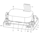
- FIG. 1 is a perspective view of a motor unit according to a first embodiment of the present invention.
- FIG. 4 is a partially enlarged perspective view of a connector receiving portion of the electric motor unit according to the first embodiment, showing a state where a connection plug provided at a distal end of the conductive cable is connected to the connector;
- FIG. 3 is a partially enlarged perspective view of a connector receiving portion of the electric motor unit according to the first embodiment, showing a state where a connection plug provided at a distal end of the conductive cable is detached from the connector;
- FIG. 3 is a partially enlarged perspective view showing a connector receiving portion of the encoder according to the first embodiment in an enlarged manner, showing a state where the connector is removed while being removed from the electric motor;
- Perspective view of grounding fitting according to Embodiment 1. The perspective view which looked at the grounding metal fitting shown in FIG. 5 from the direction shown by arrow X.
- FIG. 14 is a perspective view showing a state in which a grounding bracket and a connector according to a fourth modification are attached to an encoder housing.
- the perspective view showing the state where the grounding fitting and the connector concerning a 4th modification were attached to the encoder case, and the connection plug was connected.
- FIG. 1 is a perspective view of the electric motor unit according to the first embodiment of the present invention.
- the electric motor unit 50 includes the electric motor 10, the encoder 1, the connector 2, and the grounding metal 7.
- the electric motor 10 includes a stator housing 3, a load-side bracket 4, a non-load-side bracket 5, and a rotating shaft 6.
- the stator housing 3 is formed of a conductor and has a cylindrical shape. Note that, in the first embodiment, the case where the conductor is made of a conductor also includes a state in which the outer peripheral surface of an object made of an insulator is covered with the conductor.
- a stator not shown is fixed inside the stator housing 3.
- the stator has a cylindrical shape.
- a rotor is provided inside the stator.
- the rotating shaft 6 is connected to the rotor.
- the load-side bracket 4 is made of a conductor, and closes an opening on one end side of the stator housing 3.
- the non-load-side bracket 5 is a first housing made of a conductor, and closes an opening at the other end of the stator housing 3.
- a bearing (not shown) is fixed to the load side bracket 4 and the non-load side bracket 5.
- the bearing fixed to the load side bracket 4 and the bearing fixed to the non-load side bracket 5 rotatably support the rotating shaft 6. Thereby, the rotating shaft 6 and the rotor can be integrally rotated. A part of the rotating shaft 6 penetrates the load side bracket 4 and is exposed to the outside of the electric motor 10.
- the encoder 1 is fixed to the non-load side bracket 5 provided in the electric motor 10.
- the encoder 1 has an encoder housing 1a.
- the encoder housing 1a is a second housing made of an insulator.
- a detector that detects the rotational position of the electric motor 10 is provided inside the encoder housing 1a. The illustration of the detector is omitted. Examples of the detector include a magnetic detector using a magnetic sensor and a photodetector using a light emitting element and a light receiving element.
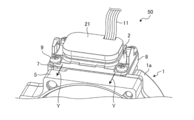
- FIG. 2 is a partially enlarged perspective view in which a connector receiving portion of the electric motor unit according to the first embodiment is enlarged, and is a diagram showing a state in which a connection plug provided at a distal end of the conductive cable is connected to the connector.
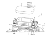
- FIG. 3 is a partially enlarged perspective view in which a connector receiving portion of the electric motor unit according to the first embodiment is enlarged, and is a diagram showing a state where a connection plug provided at a distal end of the conductive cable is detached from the connector.
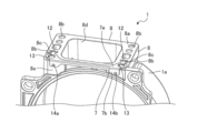
- FIG. 4 is a partially enlarged perspective view in which the connector receiving portion of the encoder according to the first embodiment is enlarged, and shows a state where the encoder is removed from the electric motor and the connector is removed from the encoder.
- the connector receiving portion 8 is provided with a connector contact surface 8a.
- the connector contact surface 8a is a first surface that faces the connector 2 and contacts the connector 2 when the connector 2 is fixed.
- a plurality of screw holes 8b used for fixing the connector 2 are formed in the connector contact surface 8a.
- the connector contact surface 8a is formed with a plurality of insertion holes 8c into which a part of a grounding metal fitting 7 described later is inserted.
- the connector contact surface 8a has a recess 8d provided with a terminal connected to a detector and the like provided inside the encoder housing 1a. Although not shown, a plurality of terminals are provided in the recess 8d.
- the plurality of terminals include a terminal connected to the electric motor 10.
- the electric motor 10 includes an electromagnetic brake
- the plurality of terminals include a terminal connected to the electromagnetic brake.
- a communication unit for communicating with an external device is provided inside the encoder housing 1a or on the electric motor 10
- the plurality of terminals include terminals connected to the communication unit.
- the connector receiving portion 8 has a bracket contact surface 8e.
- the bracket contact surface 8 e is a second surface that is opposed to the non-load side bracket 5 of the electric motor 10 and is in contact with the non-load side bracket 5.
- the connector 2 is fixed to the connector receiving portion 8 of the encoder housing 1a.
- the connector 2 is made of a conductor. As shown in FIGS. 2 and 3, the connector 2 is fixed to the connector receiving portion 8 using screws 9.
- the screw 9 for fixing the connector 2 is screwed into a screw hole 8b formed in the connector contact surface 8a.
- the connector 2 is connected to a connection plug 21 provided at the end of the conductive cable 11.
- the conductive cable 11 is configured by collecting a plurality of wires.
- the plurality of wires constituting the conductive cable 11 include a detection communication line used for communication with a detector provided inside the encoder housing 1a.
- the plurality of wires constituting the conductive cable 11 include a motive power supply line that supplies power to the electric motor 10.
- the electric motor 10 includes an electromagnetic brake
- the plurality of wires forming the conductive cable 11 include a brake power supply line that supplies power to the electromagnetic brake.
- a communication unit for communicating with an external device is provided inside the encoder housing 1a or on the electric motor 10
- a plurality of wires constituting the conductive cable 11 include a network used for communication with the external device. Communication lines are included.
- the connector 2 has terminals formed by fixing the connector 2 to the connector receiving portion 8 to be connected to terminals provided on the connector receiving portion 8.
- a plurality of wires constituting the conductive cable 11 are connected to the terminals of the connector 2. That is, by fixing the connector 2 to the connector receiving portion 8 and connecting the connection plug 21 to the connector 2, the conductive cable 11 is connected to a detector or the like. Thereby, it is possible to perform communication with the detector, supply of electric power to the electric motor 10, supply of electric power to the electromagnetic brake, and communication with the external device through the conductive cable 11.
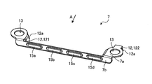
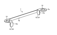
- FIG. 5 is a perspective view of the grounding bracket according to the first embodiment.
- FIG. 6 is a perspective view of the grounding fitting shown in FIG.
- the grounding member 7 is a plate-like member made of a conductor.
- the grounding fitting 7 is configured by bending a plate-shaped member, and has a first portion 7a and a second portion 7b sandwiching the bent portion.
- the grounding metal fitting 7 is attached to the connector receiving portion 8 as shown in FIG.
- the first portion 7a is arranged on the connector contact surface 8a with the grounding metal 7 attached to the connector receiving portion 8.
- the first portion 7a has a plurality of projections inserted into insertion holes 8c formed in the connector contact surface 8a with the grounding metal fitting 7 attached to the connector receiving portion 8.
- a part 12 is formed.
- Each of the protruding portions 12 is formed with a barb 12a protruding from the protruding portion 12 in a direction perpendicular to the insertion direction. Due to the formation of the barbs 12a, the protruding portions 12 have a shape that becomes narrower toward the tip. The formation of the barb 12a makes it difficult for the protrusion 12 to come out of the insertion hole 8c, and prevents the grounding metal 7 from falling off.
- a projection that hooks on the barb 12a may be formed inside the insertion hole 8c.
- the electric motor unit 50 can be assembled in a state where the ground metal 7 is attached to the connector receiving portion 8 in advance. More specifically, the connector 2 can be fixed to the connector receiving portion 8 and the encoder 1 can be fixed to the electric motor 10 in a state where the grounding metal 7 is attached to the connector receiving portion 8 in advance. Thereby, the work process required for grounding the motor unit 50 can be simplified. If the grounding metal 7 is attached to the connector receiving portion 8 in advance, either of the fixing of the connector 2 to the connector receiving portion 8 and the fixing of the encoder 1 to the electric motor 10 may be performed first.
- the first portion 7a is formed with a through hole 13 communicating with the screw hole 8b formed in the connector contact surface 8a.
- the first portion 7a is sandwiched between the encoder housing 1a and the connector 2 by fixing the connector 2 to the connector receiving portion 8. Further, a screw 9 for fixing the connector 2 is penetrated through a through hole 13 formed in the first portion 7 a, and the connector 2 and the first portion 7 a are jointly fastened to the connector receiving portion 8. Thereby, the peripheral portion of the through hole 13 in the first portion 7a can be reliably brought into contact with the connector 2.
- the second portion 7b is arranged to be in contact with the bracket contact surface 8e in a state where the grounding metal fitting 7 is attached to the connector receiving portion 8.
- the second portion 7b has two protruding protrusions 14a and 14b. Note that three or more projections may be provided.
- the protruding portions 14a and 14b are formed so as to protrude toward the non-load side bracket 5 and to protrude toward the encoder housing 1a on the back side thereof. What is necessary is just to be formed.
- the second portion 7b is sandwiched between the encoder housing 1a and the non-load-side bracket 5 by fixing the encoder 1 to the electric motor 10.
- the two protrusions 14a and 14b projecting toward the non-load side bracket 5 are in contact with the non-load side bracket 5.
- the two projections 14a and 14b that project toward the encoder housing 1a are in contact with the encoder housing 1a.
- the portion of the electric motor 10 in contact with the non-load side bracket 5 depends on which region the protrusion is provided. The distance from the outer edge can be different.
- the projections 14a and 14b projecting toward the encoder housing 1a are formed without forming the projections 14a and 14b projecting toward the non-load side bracket 5, thereby improving the assemblability of the electric motor 10. Can be achieved.
- the mounting bracket 7 is attached to the non-load-side bracket 5 with the grounding metal fitting 7 attached to the encoder housing 1a. Therefore, when the projections 14a and 14b projecting toward the non-load side bracket 5 are formed, the projections 14a and 14b are used when the anti-load side bracket 5 and the encoder housing 1a are aligned. May be caught on the non-load-side bracket 5 and the assemblability may be reduced.
- a recess may be formed at a portion where the protrusions 14a and 14b come into contact with a depth smaller than the height of the protrusions 14a and 14b.
- the encoder housing 1a is formed of an insulator, it is difficult to provide a grounding path from the connector 2 to the non-load-side bracket 5 via the encoder housing 1a.
- two grounding paths can be provided from the connector 2 made of a conductor to the non-load-side bracket 5 as shown by an arrow Y in FIG. 2. That is, from the connector 2, the first part 7 a of the grounding metal fitting 7 in contact with the connector 2, the second part 7 b continuous with the first part 7 a, and the two protrusions 14 a and 14 b of the second part 7 b And a first grounding path connected to the non-load-side bracket 5 that is in contact with the one projection 14a.
- the first part 7 a of the grounding metal fitting 7 in contact with the connector 2 the second part 7 b continuous with the first part 7 a, and the two protrusions 14 a and 14 b of the second part 7 b And a second ground path that is connected to the non-load-side bracket 5 that is in contact with the other protrusion 14b.
- the anti-load-side bracket 5 is grounded through a portion formed of a conductor such as the stator housing 3 and the load-side bracket 4 and a mounting device to which the motor unit 50 is mounted.
- the part formed by the conductor ahead of the non-load-side bracket 5 is not limited to the stator housing 3 and the load-side bracket 4, but may be any part formed by the conductor included in the electric motor 10.
- grounding fitting 7 is sandwiched between the connector 2 and the encoder housing 1a during a series of operations for fixing the connector 2 to the encoder housing 1a, and the contact with the connector 2 is ensured.
- the grounding bracket 7 is sandwiched between the encoder housing 1 a and the non-load-side bracket 5, and the contact with the anti-load-side bracket 5 is prevented. Secured. Therefore, since unnecessary work for fixing the grounding metal 7 hardly occurs, the work process required for grounding the motor unit 50 can be simplified.
- the grounding bracket 7 is fixed by the joint tightening of the first portion 7a using the screw 9 and the sandwiching between the encoder housing 1a and the non-load side bracket 5, so that the electric motor unit 50 is bent. Variations in the fixed state are less likely to occur than metal fittings fixed by processing. Therefore, it is easy to secure stable grounding performance.
- the contact point between the grounding metal 7 and the connector 2 and the contacting point between the grounding metal 7 and the non-load-side bracket 5 can be made stronger.
- two ground paths are provided, even if the encoder housing 1a is deformed due to a temperature change or aging deterioration and one ground path is lost, another ground path is lost. Can be secured.
- the robustness of the grounding performance is improved, and the noise resistance and the controllability of the motor 10 can be improved.
- the contact area between the connector 2 and the non-load-side bracket 5 can be increased.
- the grounding metal 7 is sandwiched between the connector contact surface 8a and the bracket contact surface 8e, which are surfaces continuous through the edge of the connector receiving portion 8, the contact portion with the connector 2 and the non-load side.
- the distance from the contact point with the bracket 5 can be shortened.
- the distance between the contact point with the connector 2 and the contact point with the non-load side bracket 5 can be reduced to about 3 mm.
- the contact area between the connector 2 and the anti-load side bracket 5 and the grounding metal fitting 7 is increased, and the distance between the contact point with the connector 2 and the contact point with the anti-load side bracket 5 is shortened. Resistance can be further reduced. By making the contact resistance smaller, it is possible to obtain a more preferable grounding structure capable of stabilizing controllability and improving environmental resistance.
- the contact between the connector 2 and the non-load-side bracket 5 and the grounding metal 7 may be achieved only by the plate surface without providing the protrusions 14a and 14b.
- FIG. 7 is a perspective view showing a first modified example of the grounding fitting in the first embodiment.
- FIG. 8 is a perspective view of the grounding fitting shown in FIG.
- a plurality of projections 15a, 15b, 15c, 15d are formed on the second portion 7b.
- the plurality of protrusions 15 a, 15 b, 15 c, and 15 d are formed so as to protrude toward the non-load-side bracket 5 with the grounding metal 7 attached to the connector receiving portion 8.
- each of the plurality of protrusions 15a, 15b, 15c, and 15d is a contact point that comes into contact with the non-load-side bracket 5. Therefore, when the grounding metal fitting 7 according to the first modification is used, four grounding paths can be provided.
- the number of protrusions formed on the second portion 7b may be three, or may be five or more.
- a plurality of projections 15a, 15b, 15c, 15d may be projected toward the encoder housing 1a.
- a plurality of projections 15a, 15b, 15c, 15d projecting toward the non-load side bracket 5 and a plurality of projections 15a, 15b, 15c, 15d projecting toward the encoder housing 1a may be provided.
- the protrusion direction of the return 12a differs between the plurality of protrusions 12. More specifically, when viewed along the insertion direction of the protrusion 12, the protrusion direction of the barb 12a formed on one protrusion 121 and the protrusion direction of the barb 12a formed on the other protrusion 122 Differ by 90 °. By making the protruding direction of the barbs 12a different, when a force is applied to the grounding metal fitting 7 attached to the encoder housing 1a, different barbs 12a are caught in the insertion holes 8c in accordance with the direction of the force. become.
- the wobble of the grounding fitting 7 is suppressed by being hooked inside. As described above, the wobble of the grounding metal 7 can be suppressed with respect to forces applied from various directions, and the stability of the grounding metal 7 attached to the encoder housing 1a can be improved.
- the configuration in which the protrusion 12 and the barb 12a are provided on the grounding metal fitting 7 and the configuration in which the protruding direction of the barb 12a is different can be applied to the other grounding metal fittings 7 exemplified in the first embodiment.
- FIG. 9 is a perspective view showing a second modification of the grounding fitting in the first embodiment.
- An opening 16 extending in the longitudinal direction is formed in the second portion 7b of the grounding metal fitting 7 according to the second modification.
- the portion where the opening 16 is formed is subjected to a bending process that is convex toward the non-load-side bracket 5.
- Projections 17a, 17b, 17c projecting toward the non-load-side bracket 5 are formed on the second portion 7b by bending.
- the projections 17a, 17b, 17c constitute contact points that come into contact with the non-load-side bracket 5.
- the protrusions 17a, 17b, 17c and the non-load side correspond to the widening of the gap that may occur due to the dimensional tolerance of the encoder housing 1a and the dimensional tolerance of the non-load side bracket 5, for example, the widening of the interval of ⁇ 1 mm or less. Contact with the bracket 5 is ensured.
- the projections 15a, 15b, 15c, and 15d shown in FIG. 7 are also made to protrude so as to have an arc-shaped cross section, and can be made of a thin sheet metal to exert an urging force. For example, a thin sheet metal having a thickness of 0.35 mm or less may be used.
- FIG. 10 is a perspective view showing a third modification of the grounding bracket according to the first embodiment.
- the first portion 7a is also bent into a portion where the opening 16a is formed. Is given.
- the protruding portions 22a, 22b, 22c protruding toward the connector 2 are also formed on the first portion 7a.
- the protrusions 22a, 22b, and 22c constitute contact points that come into contact with the connector 2.
- the projecting portions 22a, 22b, and 22c are biased by a restoring force in a direction in which the distance between the encoder housing 1a and the connector 2 is increased. Is a second urging portion that exerts the following.
- FIG. 11 is a perspective view showing a fourth modification of the grounding metal fitting in the first embodiment.
- FIG. 12 is a perspective view showing a state in which a grounding bracket and a connector according to a fourth modification are attached to an encoder housing.
- FIG. 13 is a perspective view showing a state in which a grounding bracket and a connector according to a fourth modification are attached to an encoder housing and a connection plug is connected.
- the grounding metal fitting 7 has a third portion 7c which is connected to the second portion 7b and is sandwiched between the connection plug 21 and the connector 2. As shown in FIG. 11, the third portion 7c is bent so as to project toward the connection plug 21. Protrusions 18a and 18b projecting toward the connection plug 21 are formed on the third portion 7c by bending. The protrusions 18a and 18b constitute contact points that come into contact with the connection plug 21. Further, when the protrusions 18a and 18b are sandwiched between the connection plug 21 and the connector 2 and are crushed, the projections 18a and 18b exert a biasing force in a direction to increase the distance between the connection plug 21 and the connector 2 by a restoring force. 3 is the urging portion.
- the number of protrusions 18a and 18b formed on the third portion 7c is not limited to two, but may be one, or may be three or more.
- connection plug 21 is formed of a conductor, so that the connection plug 21 is connected to the non-load side bracket 5 through the grounding metal 7 without the intervention of the connector 2. To the ground path. That is, by increasing the number of grounding paths, it is possible to improve the robustness of the grounding performance.
- a U-shaped notch 19 is formed in the second portion 7b.
- a portion surrounded by the notch 19 is bent toward the non-load-side bracket 5 to form a projection 20 that is a contact.
- the projecting portion 20 is biased in a direction in which the space between the encoder housing 1a and the non-load-side bracket 5 is widened by the restoring force. Is a first urging portion that exerts the following.
- the protrusions 18a and 18b which are contact points, can be brought into contact with the connector 2 in accordance with the increase in the distance between the encoder housing 1a and the non-load-side bracket 5.
Landscapes
- Engineering & Computer Science (AREA)
- Power Engineering (AREA)
- Motor Or Generator Frames (AREA)
Abstract
電動機ユニット(50)は、導体で構成された第1筐体(5)を有する電動機(10)と、絶縁体で構成されて第1筐体(5)に取り付けられる第2筐体(1a)と、導電ケーブルの先端に設けられたプラグが接続可能されて第2筐体(1a)に固定されるコネクタ(2)と、コネクタ(2)と第2筐体(1a)との間に挟み込まれる第1の部分と、第1筐体(5)と第2筐体(1a)との間に挟み込まれる第2の部分とを有する板状の接地部品と、を備える。
Description
本発明は、コネクタが固定される電動機ユニットに関する。
電動機では、電源の供給に用いる電源線等を有する導電ケーブルを電動機に接続するために、導電ケーブルの先端に設けられたプラグと、電動機に設けられたコネクタが接続されて固定される。このような電動機には、電動機の筐体とは別に、コネクタが固定される別の筐体が設けられる場合がある。この場合、電動機の筐体とコネクタとは直接接触せず、電動機の筐体とコネクタとの間には別の筐体が介在する。
別の筐体が絶縁体で構成されている場合には、電動機の筐体と別の筐体とコネクタとを組み付けただけでは、電動機の筐体を介してコネクタを接地することができない。そのため、コネクタを接地するために、リード線等の専用部品を用意し、リード線の両端をコネクタと電動機の筐体の両方にねじで固定したり、半田付けによって固定したりする必要があった。
しかしながら、リード線を用いた接地では、ねじの締結またははんだ付けによってリード線を取り付けるための作業工数が増えて接地に要する作業の効率が低下する問題があった。特許文献1では、折り曲げ可能な接地用の金具を用いた構成が開示されている。特許文献1に開示された金具は、一端はねじを用いてシールド板に固定し、他端は基板に形成された孔に差し込みつつ折り曲げて固定することで、シールド板と基板とを金具で接続させて接地が図られている。
しかしながら、上記従来の技術によれば、金具の折り曲げによって他端を基板に固定できるので、接地に要する作業工程の容易化は図られているが、折り曲げの状態によって接地の信頼性にばらつきが生じやすく、接地性能のロバスト性が低くなってしまうという問題があった。
本発明は、上記に鑑みてなされたものであって、接地に要する作業工程の容易化を維持しつつ接地性能のロバスト性の向上が図られた電動機ユニットを得ることを目的とする。
上述した課題を解決し、目的を達成するために、本発明は、導体で構成された第1筐体を有する電動機と、絶縁体で構成されて第1筐体に取り付けられる第2筐体と、導電ケーブルの先端に設けられたプラグが接続可能とされて第2筐体に固定されるコネクタと、コネクタと第2筐体との間に挟み込まれる第1の部分と、第1筐体と第2筐体との間に挟み込まれる第2の部分とを有する板状の接地部品と、を備える。
本発明にかかる電動機ユニットによれば、接地に要する作業工程の容易化を維持しつつ接地性能のロバスト性の向上を図ることができるという効果を奏する。
以下に、本発明の実施の形態にかかる電動機ユニットを図面に基づいて詳細に説明する。なお、この実施の形態によりこの発明が限定されるものではない。
実施の形態1.
図1は、本発明の実施の形態1にかかる電動機ユニットの斜視図である。電動機ユニット50は、電動機10と、エンコーダ1と、コネクタ2と、接地金具7とを備える。電動機10は、固定子筐体3と、負荷側ブラケット4と、反負荷側ブラケット5と、回転軸6とを有する。固定子筐体3は、導体で構成され、筒状の形状となっている。なお、本実施の形態1において、導体で構成されている、といった場合には、絶縁体で構成された物の外周面が導体で覆われている状態も含むものとする。固定子筐体3の内側には、図示を省略した固定子が固定されている。固定子は、筒状の形状となっている。固定子の内側には、回転子が設けられている。回転子には、回転軸6が連結されている。
図1は、本発明の実施の形態1にかかる電動機ユニットの斜視図である。電動機ユニット50は、電動機10と、エンコーダ1と、コネクタ2と、接地金具7とを備える。電動機10は、固定子筐体3と、負荷側ブラケット4と、反負荷側ブラケット5と、回転軸6とを有する。固定子筐体3は、導体で構成され、筒状の形状となっている。なお、本実施の形態1において、導体で構成されている、といった場合には、絶縁体で構成された物の外周面が導体で覆われている状態も含むものとする。固定子筐体3の内側には、図示を省略した固定子が固定されている。固定子は、筒状の形状となっている。固定子の内側には、回転子が設けられている。回転子には、回転軸6が連結されている。
負荷側ブラケット4は、導体で構成され、固定子筐体3の一端側の開口を塞ぐ。反負荷側ブラケット5は、導体で構成された第1筐体であり、固定子筐体3の他端側の開口を塞ぐ。負荷側ブラケット4と反負荷側ブラケット5には、図示を省略した軸受が固定されている。負荷側ブラケット4に固定された軸受と、反負荷側ブラケット5に固定された軸受は、回転軸6を回転可能に支持する。これにより、回転軸6と回転子とが一体で回転可能とされる。回転軸6の一部は、負荷側ブラケット4を貫通して電動機10の外部に露出している。
エンコーダ1は、電動機10が備える反負荷側ブラケット5に固定されている。エンコーダ1は、エンコーダ筐体1aを有する。エンコーダ筐体1aは、絶縁体で構成された第2筐体である。エンコーダ筐体1aの内部には、電動機10の回転位置を検出する検出器が設けられる。なお、検出器の図示は省略している。検出器には、例えば磁気センサを用いた磁気検出器、発光素子および受光素子を用いた光検出器が挙げられる。
エンコーダ筐体1aには、コネクタ2が固定されるコネクタ受け部8が一体に形成されている。なお、別体で形成されたコネクタ受け部8とエンコーダ筐体1aとを有して第2筐体が構成されてもよい。図2は、実施の形態1にかかる電動機ユニットのコネクタ受け部部分を拡大した部分拡大斜視図であって、導電ケーブルの先端に設けられた接続プラグがコネクタに接続された状態を示す図である。図3は、実施の形態1にかかる電動機ユニットのコネクタ受け部部分を拡大した部分拡大斜視図であって、導電ケーブルの先端に設けられた接続プラグがコネクタから外れた状態を示す図である。図4は、実施の形態1におけるエンコーダのコネクタ受け部部分を拡大した部分拡大斜視図であって、エンコーダが電動機から取り外され、かつエンコーダからコネクタが取り外された状態を示す図である。
図4に示すように、コネクタ受け部8にはコネクタ接面8aが形成されている。コネクタ接面8aは、コネクタ2が固定された状態において、コネクタ2と対向してコネクタ2に接する第1面である。コネクタ接面8aには、コネクタ2を固定する際に使用される複数のねじ穴8bが形成されている。コネクタ接面8aには、後述する接地金具7の一部が差し込まれる複数の差し込み穴8cが形成されている。
コネクタ接面8aには、エンコーダ筐体1aの内部に設けられた検出器等につながる端子が設けられた凹部8dが形成されている。図示を省略しているが、凹部8dには複数の端子が設けられている。複数の端子には、電動機10につながる端子も含まれる。また、電動機10が、電磁ブレーキを備える場合には、複数の端子には電磁ブレーキにつながる端子も含まれる。また、エンコーダ筐体1aの内部または電動機10に、外部機器と通信する通信部が設けられている場合には、複数の端子には通信部につながる端子も含まれる。
コネクタ受け部8には、ブラケット接面8eが形成されている。ブラケット接面8eは、電動機10の反負荷側ブラケット5と対向して反負荷側ブラケット5に接する第2面である。
コネクタ2は、エンコーダ筐体1aのコネクタ受け部8に固定される。コネクタ2は、導体で構成されている。図2および図3に示すように、コネクタ2は、ねじ9を用いてコネクタ受け部8に固定される。コネクタ2を固定するねじ9は、コネクタ接面8aに形成されたねじ穴8bにねじ込まれている。コネクタ2には、導電ケーブル11の先端に設けられた接続プラグ21が接続されている。導電ケーブル11は、複数の配線をまとめて構成される。
導電ケーブル11を構成する複数の配線には、エンコーダ筐体1aの内部に設けられた検出器との通信に用いられる検出用通信線が含まれる。また、導電ケーブル11を構成する複数の配線には、電動機10に電力を供給する動力電源線が含まれる。また、電動機10が、電磁ブレーキを備える場合には、導電ケーブル11を構成する複数の配線には、電磁ブレーキに電力を供給するブレーキ用電源線が含まれる。また、エンコーダ筐体1aの内部または電動機10に、外部機器と通信する通信部が設けられている場合には、導電ケーブル11を構成する複数の配線には、外部機器との通信に用いられるネットワーク通信線が含まれる。
コネクタ2には、コネクタ2をコネクタ受け部8に固定することで、コネクタ受け部8に設けられた端子と接続される端子が形成されている。導電ケーブル11の先端に設けられた接続プラグ21をコネクタ2に接続することで、導電ケーブル11を構成する複数の配線がコネクタ2の端子に接続される。すなわち、コネクタ2をコネクタ受け部8に固定し、接続プラグ21をコネクタ2と接続することで、導電ケーブル11が検出器等に接続される。これにより、導電ケーブル11を通じての検出器との通信、電動機10への電力の供給、電磁ブレーキへの電力の供給、外部機器との通信を行うことが可能となる。
図5は、実施の形態1における接地金具の斜視図である。図6は、図5に示す接地金具を矢印Xに示す方向から見た斜視図である。接地金具7は、導体で構成された板状の部材である。接地金具7は、板状の部材を折り曲げて構成されており、折り曲げ箇所を挟んだ第1の部分7aと第2の部分7bとを有する。
接地金具7は、図4に示すように、コネクタ受け部8に取り付けられる。第1の部分7aは、接地金具7がコネクタ受け部8に取り付けられた状態で、コネクタ接面8a上に配置される。図5および図6に示すように、第1の部分7aには、接地金具7がコネクタ受け部8に取り付けられた状態で、コネクタ接面8aに形成された差し込み穴8cに差し込まれる複数の突部12が形成されている。突部12のそれぞれには、突部12に差し込み方向に対して垂直な方向に突出した返し12aが形成されている。返し12aが形成されていることで、突部12は先端に向けて幅が細くなる形状となっている。返し12aが形成されていることで、突部12が差し込み穴8cから抜けにくくなり、接地金具7の抜け落ちが防がれる。差し込み穴8cの内側には、返し12aに引っ掛かる突起が形成されていてもよい。
突部12および返し12aによって、コネクタ受け部8に取り付けられた接地金具7が脱落しにくくなる。したがって、コネクタ受け部8に接地金具7を予め取り付けた状態で、電動機ユニット50の組立作業を行うことができる。より具体的には、コネクタ受け部8に接地金具7を予め取り付けた状態で、コネクタ受け部8へのコネクタ2の固定、および電動機10へのエンコーダ1の固定を行うことができる。これにより、電動機ユニット50の接地に要する作業工程の容易化を図ることができる。なお、コネクタ受け部8に接地金具7を予め取り付けた状態であれば、コネクタ受け部8へのコネクタ2の固定と、電動機10へのエンコーダ1の固定はどちらを先に実施してもよい。
第1の部分7aには、コネクタ接面8aに形成されたねじ穴8bと連通する貫通孔13が形成されている。第1の部分7aは、コネクタ受け部8にコネクタ2が固定されることで、エンコーダ筐体1aとコネクタ2との間に挟み込まれる。また、コネクタ2を固定するねじ9が、第1の部分7aに形成された貫通孔13に貫通され、コネクタ受け部8に対してコネクタ2と第1の部分7aとが共締めされる。これにより、第1の部分7aにおける貫通孔13の周囲部分をコネクタ2に確実に接触させることができる。
第2の部分7bは、接地金具7がコネクタ受け部8に取り付けられた状態で、ブラケット接面8eに接するように配置される。第2の部分7bは、突出した2つの突起部14a,14bを有する。なお、突起部は3つ以上設けられていてもよい。突起部14a,14bは、反負荷側ブラケット5に向けて突出するものと、その裏側でエンコーダ筐体1aに向けて突出するものとが形成されているが、いずれか一方に向けて突出するものが形成されていればよい。
第2の部分7bは、エンコーダ1が電動機10に固定されることで、エンコーダ筐体1aと反負荷側ブラケット5との間に挟み込まれる。2つの突起部14a,14bは、反負荷側ブラケット5に向けて突出するものは、反負荷側ブラケット5に接する。2つの突起部14a,14bは、エンコーダ筐体1aに向けて突出するものは、エンコーダ筐体1aに接する。エンコーダ筐体1aに接する部分が押し込まれることで、その2箇所で第2の部分7bを反負荷側ブラケット5に当接させることができる。すなわち、接地金具7は、2箇所で反負荷側ブラケット5に接することとなる。なお、第2の部分7bは、第1の部分7aからの突出量が異なる領域を有しているので、突起をどの領域に設けるかによって、反負荷側ブラケット5に接する箇所の、電動機10の外縁からの距離を異ならせることができる。
なお、反負荷側ブラケット5に向けて突出する突起部14a,14bを形成せずに、エンコーダ筐体1aに向けて突出する突起部14a,14bを形成することで、電動機10の組立性の向上を図ることが可能となる。上述したように、エンコーダ筐体1aに接地金具7が取り付けられた状態で、反負荷側ブラケット5に取り付けられる。そのため、反負荷側ブラケット5に向けて突出する突起部14a,14bが形成されていた場合には、反負荷側ブラケット5とエンコーダ筐体1aとを位置合わせをする際に、突起部14a,14bが反負荷側ブラケット5に引っ掛かって、組立性が低下する場合がある。一方、反負荷側ブラケット5に向けて突出する突起部14a,14bを形成しなければ、反負荷側ブラケット5とエンコーダ筐体1aとの位置合わせが容易になり、電動機10組立性の向上が図られる。また、エンコーダ筐体1aのブラケット接面8eには、突起部14a,14bが当接する部分に、突起部14a,14bの高さよりも小さい深さで凹みが形成されていてもよい。この凹みに突起部14a,14bが嵌まることで、接地金具7の位置ずれを抑えることができる。また、突起部14a,14bの高さよりも小さい深さで凹みが形成されていれば、突起部14a,14bを凹みの底に確実に当接させることができる。
以上説明した電動機ユニット50では、エンコーダ筐体1aが絶縁体で構成されているため、エンコーダ筐体1aを介してコネクタ2から反負荷側ブラケット5につながる接地経路を設けることは困難である。しかしながら、接地金具7を設けることで、図2において矢印Yで示すように、導体で構成されたコネクタ2から反負荷側ブラケット5に向かう2本の接地経路を設けることができる。すなわち、コネクタ2から、コネクタ2に接する接地金具7の第1の部分7a、第1の部分7aと連続する第2の部分7b、第2の部分7bが有する2つの突起部14a,14bのうちの一方の突起部14a、一方の突起部14aに接する反負荷側ブラケット5と繋がる1本目の接地経路が設けられる。また、コネクタ2から、コネクタ2に接する接地金具7の第1の部分7a、第1の部分7aと連続する第2の部分7b、第2の部分7bが有する2つの突起部14a,14bのうちの他方の突起部14b、他方の突起部14bに接する反負荷側ブラケット5と繋がる2本目の接地経路が設けられる。なお、反負荷側ブラケット5からは、固定子筐体3、負荷側ブラケット4等の導体で構成された箇所、電動機ユニット50が取り付けられた取付先装置を介して接地される。なお、反負荷側ブラケット5から先の導体で構成された箇所は、固定子筐体3および負荷側ブラケット4に限られず、電動機10が有する導体で構成された部品であればよい。
接地金具7は、コネクタ2をエンコーダ筐体1aに固定するための一連の作業の中で、コネクタ2とエンコーダ筐体1aとに挟み込まれ、コネクタ2との接触が確保される。また、接地金具7は、エンコーダ1を電動機10に固定するための一連の作業の中で、エンコーダ筐体1aと反負荷側ブラケット5との間に挟み込まれ、反負荷側ブラケット5との接触が確保される。したがって、接地金具7を固定するための余計な作業がほとんど発生しないため、電動機ユニット50の接地に要する作業工程の容易化を図ることができる。
また、電動機ユニット50では、ねじ9を用いた第1の部分7aの共締め、およびエンコーダ筐体1aと反負荷側ブラケット5との間への挟み込みによって、接地金具7が固定されるので、折り曲げ加工によって固定する金具に比べて、固定状態にばらつきが生じにくい。そのため、安定した接地性能を確保しやすくなる。
リード線を用いた接地に比べて、接地金具7とコネクタ2との接触箇所および接地金具7と反負荷側ブラケット5との接触箇所を強固にすることができる。また、2つの接地経路を設けているので、例えば温度変化または経年劣化によってエンコーダ筐体1aが変形して1本の接地経路が失われた場合であっても、別のもう1本の接地経路を確保することができる。このように、電動機ユニット50では接地性能のロバスト性の向上を図り、耐ノイズ性および電動機10の制御性の向上を図ることができる。
また、接地金具7は、第1の部分7aおよび第2の部分7bが板状であるため、コネクタ2および反負荷側ブラケット5との接触面積を大きくすることができる。また、コネクタ受け部8のうち縁を介して連続する面であるコネクタ接面8aとブラケット接面8eとを利用して接地金具7を挟み込んでいるので、コネクタ2との接触箇所と反負荷側ブラケット5との接触箇所との距離を短くすることができる。例えば、コネクタ2との接触箇所と反負荷側ブラケット5との接触箇所との距離を3mm程度と短くすることができる。
このように、コネクタ2および反負荷側ブラケット5と接地金具7との接触面積を大きくし、コネクタ2との接触箇所と反負荷側ブラケット5との接触箇所との距離を短くすることで、接触抵抗をより小さくすることができる。接触抵抗をより小さくすることで、制御性の安定化、および耐環境性の向上を図ることのできるより好適な接地構造を得ることができる。なお、突起部14a,14bを設けずに板面だけで、コネクタ2および反負荷側ブラケット5と接地金具7との接触を図ってもよい。
図7は、実施の形態1における接地金具の第1の変形例を示す斜視図である。図8は、図7に示す接地金具を矢印Aに示す方向から見た斜視図である。第1の変形例にかかる接地金具7では、第2の部分7bに複数の突起15a,15b,15c,15dが形成されている。複数の突起15a,15b,15c,15dは、接地金具7がコネクタ受け部8に取り付けられた状態で反負荷側ブラケット5に向けて突出するように形成されている。
したがって、複数の突起15a,15b,15c,15dのそれぞれが、反負荷側ブラケット5に接触する接点となる。したがって、第1の変形例にかかる接地金具7を用いた場合には、4つの接地経路を設けることができる。なお、第2の部分7bに形成される突起の数は、3つであってもよいし、5つ以上であってもよい。また、複数の突起15a,15b,15c,15dをエンコーダ筐体1aに向けて突出させてもよい。また、反負荷側ブラケット5に向けて突出する複数の突起15a,15b,15c,15dと、エンコーダ筐体1aに向けて突出する複数の突起15a,15b,15c,15dとを設けてもよい。
また、第1の変形例にかかる接地金具7では、複数の突部12同士で返し12aの突出方向が異なっている。より具体的には、突部12の差し込み方向に沿って見た場合に、一の突部121に形成された返し12aの突出方向と、他の突部122に形成された返し12aの突出方向は、90°異なっている。返し12aの突出方向を異ならせることで、エンコーダ筐体1aに取り付けられた接地金具7に力が加えられた際に、その力の方向に合わせて異なる返し12aが差し込み穴8cの内部に引っ掛かるようになる。例えば、第2の部分7bの長手方向を中心として接地金具7を回転させるような力が加えられた場合には、一の突部121に形成された返し12aが差し込み穴8cの内部に引っ掛かって、接地金具7のぐらつきが抑えられる。また、第2の部分7bの板面に垂直な軸を中心に接地金具7を回転させるような力が加えられた場合には、一の突部121に形成された返し12aが差し込み穴8cの内部に引っ掛かって、接地金具7のぐらつきが抑えられる。このように、様々な方向から加えられる力に対して接地金具7のぐらつきを抑えられるようになり、エンコーダ筐体1aに取り付けられた接地金具7の安定性の向上を図ることができる。このように、突部12および返し12aを接地金具7に設ける構成、および返し12aの突出方向を異ならせる構成は、本実施の形態1で例示する他の接地金具7にも適用可能である。
図9は、実施の形態1における接地金具の第2の変形例を示す斜視図である。第2の変形例にかかる接地金具7の第2の部分7bには、長手方向に延びる開口16が形成されている。開口16が形成された部分では、反負荷側ブラケット5に向けて凸となる折り曲げ加工が施されている。第2の部分7bには、折り曲げ加工によって反負荷側ブラケット5に向けて突出する突起部17a,17b,17cが形成される。突起部17a,17b,17cは、反負荷側ブラケット5に接触する接点を構成する。また、突起部17a,17b,17cは、エンコーダ筐体1aと反負荷側ブラケット5との間に挟み込まれて潰された場合に、復元力によってエンコーダ筐体1aと反負荷側ブラケット5との間隔を広げる方向に付勢力を発揮する第1の付勢部となる。
接点である突起部17a,17b,17cが付勢力を発揮することで、エンコーダ筐体1aと反負荷側ブラケット5との間隔が広がった場合に、その間隔の広がりに追従して突起部17a,17b,17cが変形する。これにより、エンコーダ筐体1aと反負荷側ブラケット5との間隔が広がった場合であっても、突起部17a,17b,17cと反負荷側ブラケット5との接触が確保される。また、エンコーダ筐体1aの寸法公差および反負荷側ブラケット5の寸法公差によって発生しうる間隔の広がり、例えば±1mm以下の間隔の広がりに対応して、突起部17a,17b,17cと反負荷側ブラケット5との接触が確保される。なお、図7に示した突起15a,15b,15c,15dも、断面が円弧形状となるように突出させるとともに、薄肉板金で構成することで、付勢力を発揮させることが可能となる。例えば、厚さが0.35mm以下の薄肉板金を用いればよい。
図10は、実施の形態1における接地金具の第3の変形例を示す斜視図である。第3の変形例にかかる接地金具7では、図9の第2の変形例で示した突起部17a,17b,17cの他に、第1の部分7aでも開口16aが形成された部分に折り曲げ加工が施されている。これにより、第1の部分7aにも、コネクタ2に向けて突出する突起部22a,22b,22cが形成される。突起部22a,22b,22cは、コネクタ2に接触する接点を構成する。また、突起部22a,22b,22cは、エンコーダ筐体1aとコネクタ2との間に挟み込まれて潰された場合に、復元力によってエンコーダ筐体1aとコネクタ2との間隔を広げる方向に付勢力を発揮する第2の付勢部となる。
図11は、実施の形態1における接地金具の第4の変形例を示す斜視図である。図12は、第4の変形例にかかる接地金具とコネクタとがエンコーダ筐体に取り付けられた状態を示す斜視図である。図13は、第4の変形例にかかる接地金具とコネクタとがエンコーダ筐体に取り付けられるとともに接続プラグが接続された状態を示す斜視図である。
第4の変形例にかかる接地金具7は、第2の部分7bとつながり、接続プラグ21とコネクタ2との間に挟み込まれる第3の部分7cを有する。図11に示すように、第3の部分7cには、接続プラグ21に向けて凸となる折り曲げ加工が施されている。第3の部分7cには、折り曲げ加工によって接続プラグ21に向けて突出する突起部18a,18bが形成される。突起部18a,18bは、接続プラグ21に接触する接点を構成する。また、突起部18a,18bは、接続プラグ21とコネクタ2との間に挟み込まれて潰された場合に、復元力によって接続プラグ21とコネクタ2との間隔を広げる方向に付勢力を発揮する第3の付勢部となる。なお、第3の部分7cに形成される突起部18a,18bの数は、2個に限られず、1個であってもよいし、3個以上であってもよい。
第4の変形例にかかる接地金具7を用いた場合には、接続プラグ21を導体で構成することで、コネクタ2を介さずに、接地金具7を介して接続プラグ21から反負荷側ブラケット5につながる接地経路を設けることができる。すなわち、接地経路を増やして、接地性能のロバスト性の向上を図ることができる。
また、第4の変形例にかかる接地金具7では、コ字状の切り欠き19が第2の部分7bに形成されている。また、切り欠き19に囲まれた部分が、反負荷側ブラケット5に向けて折り曲げられて接点である突起部20を構成する。突起部20は、エンコーダ筐体1aと反負荷側ブラケット5との間に挟み込まれて潰された場合に、復元力によってエンコーダ筐体1aと反負荷側ブラケット5との間隔を広げる方向に付勢力を発揮する第1の付勢部となる。これにより、エンコーダ筐体1aと反負荷側ブラケット5との間隔の広がりに対応して、接点である突起部18a,18bをコネクタ2に接触させることができる。
以上の実施の形態に示した構成は、本発明の内容の一例を示すものであり、別の公知の技術と組み合わせることも可能であるし、本発明の要旨を逸脱しない範囲で、構成の一部を省略、変更することも可能である。
1 エンコーダ、1a エンコーダ筐体、2 コネクタ、3 固定子筐体、4 負荷側ブラケット、5 反負荷側ブラケット、6 回転軸、7 接地金具、8 コネクタ受け部、8a コネクタ接面、8b ねじ穴、8c 差し込み穴、8d 凹部、8e ブラケット接面、9 ねじ、10 電動機、11 導電ケーブル、12 突部、12a 返し、13 貫通孔、14a,14b 突起部、15a,15b,15c,15d 突起、16 開口、17a,17b,17c,18a,18b,20 突起部、19 切り欠き、21 接続プラグ、50 電動機ユニット、121 一の突部、122 他の突部。
Claims (12)
- 導体で構成された第1筐体を有する電動機と、
絶縁体で構成されて前記第1筐体に取り付けられる第2筐体と、
導電ケーブルの先端に設けられたプラグが接続可能とされて前記第2筐体に固定されるコネクタと、
前記コネクタと前記第2筐体との間に挟み込まれる第1の部分と、前記第1筐体と前記第2筐体との間に挟み込まれる第2の部分とを有する板状の接地部品と、を備えることを特徴とする電動機ユニット。 - 前記第2筐体は、前記コネクタと接する第1面と、前記第1面と連続して形成されて前記第1筐体と接する第2面と、を有し、
前記第1の部分は、前記第1面と前記コネクタとの間に挟み込まれ、
前記第2の部分は、前記第2面と前記第1筐体との間に挟み込まれることを特徴とする請求項1に記載の電動機ユニット。 - 前記第2の部分には、前記第1筐体または前記第2筐体と接する、前記第1筐体または前記第2筐体に向けて突出した突起部が複数設けられていることを特徴とする請求項1または2に記載の電動機ユニット。
- 前記第2の部分には、前記コネクタと前記第1筐体との間隔を広げる方向に付勢力を発揮する第1の付勢部が形成されており、前記第1の付勢部が前記突起部となることを特徴とする請求項3に記載の電動機ユニット。
- 前記第1の部分には、前記第1筐体と前記第2筐体との間隔を広げる方向に付勢力を発揮する第2の付勢部が形成されていることを特徴とする請求項1から4のいずれか1つに記載の電動機ユニット。
- 前記接地部品は、前記第2の部分とつながり、前記プラグと前記第2筐体との間に挟み込まれる第3の部分を有することを特徴とする請求項1から4のいずれか1つに記載の電動機ユニット。
- 前記第3の部分には、前記プラグと前記第2筐体との間隔を広げる方向に付勢力を発揮する第3の付勢部が形成されていることを特徴とする請求項6に記載の電動機ユニット。
- 前記第2筐体には、複数の穴が形成され、
前記第1の部分には、複数の前記穴にそれぞれが差し込まれる複数の突部が形成され、
複数の前記突部のそれぞれには、前記突部の差し込み方向に対して垂直な方向に突出して、前記穴からの前記接地部品の抜け落ちを防ぐ返しが形成されていることを特徴とする請求項1から7のいずれか1つに記載の電動機ユニット。 - 複数の前記突部のうちの少なくとも1つである一の突部には、他の突部に形成された前記返しの突出方向と異なる方向に突出する前記返しが形成されていることを特徴とする請求項8に記載の電動機ユニット。
- 前記差し込み方向に沿って見た場合に、前記一の突部からの前記返しの突出方向と、前記他の突部からの前記返しの突出方向とは、90°異なることを特徴とする請求項9に記載の電動機ユニット。
- 前記導電ケーブルは、
前記電動機に電力を供給する動力電源線と、前記第1筐体の内部に設けられた検出器との通信に用いられる検出用通信線と、を有することを特徴とする請求項1から10のいずれか1つに記載の電動機ユニット。 - 前記導電ケーブルは、
前記電動機に組み込まれた電磁ブレーキに電力を供給するブレーキ用電源線および外部機器とのネットワーク通信に用いられるネットワーク通信線の少なくともいずれか一方をさらに有することを特徴とする請求項11に記載の電動機ユニット。
Priority Applications (2)
| Application Number | Priority Date | Filing Date | Title |
|---|---|---|---|
| CN201880096164.5A CN112514213A (zh) | 2018-08-03 | 2018-11-05 | 电动机单元 |
| JP2019524481A JP6591125B1 (ja) | 2018-08-03 | 2018-11-05 | 電動機ユニット |
Applications Claiming Priority (2)
| Application Number | Priority Date | Filing Date | Title |
|---|---|---|---|
| JP2018-147090 | 2018-08-03 | ||
| JP2018147090 | 2018-08-03 |
Publications (1)
| Publication Number | Publication Date |
|---|---|
| WO2020026464A1 true WO2020026464A1 (ja) | 2020-02-06 |
Family
ID=69232594
Family Applications (1)
| Application Number | Title | Priority Date | Filing Date |
|---|---|---|---|
| PCT/JP2018/040987 Ceased WO2020026464A1 (ja) | 2018-08-03 | 2018-11-05 | 電動機ユニット |
Country Status (2)
| Country | Link |
|---|---|
| CN (1) | CN112514213A (ja) |
| WO (1) | WO2020026464A1 (ja) |
Cited By (4)
| Publication number | Priority date | Publication date | Assignee | Title |
|---|---|---|---|---|
| CN111245137A (zh) * | 2020-03-16 | 2020-06-05 | 雷勃电气(无锡)有限公司 | 一种带有力矩检测与径向冷却功能的底盘测功机电机机座 |
| WO2021213774A1 (de) * | 2020-04-23 | 2021-10-28 | Robert Bosch Gmbh | Antriebsvorrichtung für ein fahrzeug und fahrzeug |
| CN114204741A (zh) * | 2020-09-17 | 2022-03-18 | 泰科电子日本合同会社 | 接地用部件 |
| JP2025526579A (ja) * | 2022-08-25 | 2025-08-15 | 安徽三竹智能科技股▲ふん▼有限公司 | 低電力信号用のネジ・クイックロック兼用構造 |
Citations (7)
| Publication number | Priority date | Publication date | Assignee | Title |
|---|---|---|---|---|
| JP2003514499A (ja) * | 1999-11-19 | 2003-04-15 | エマーソン エレクトリック カンパニー | 電気デバイス接地システム |
| JP2011223656A (ja) * | 2010-04-05 | 2011-11-04 | Asmo Co Ltd | モータ |
| JP2012195066A (ja) * | 2011-03-15 | 2012-10-11 | Sumitomo Wiring Syst Ltd | シールドシェルの取付構造 |
| JP2016510207A (ja) * | 2013-05-23 | 2016-04-04 | ニュモテク株式会社New Motech Co., Ltd. | モーター接地構造 |
| JP2016152177A (ja) * | 2015-02-19 | 2016-08-22 | 日立オートモティブシステムズ株式会社 | 電子制御装置、電動機用制御装置及び電動流体ポンプ |
| WO2018047342A1 (ja) * | 2016-09-12 | 2018-03-15 | 三菱電機株式会社 | モータ制御装置及び電動パワーステアリング制御装置 |
| JP2018117105A (ja) * | 2017-01-21 | 2018-07-26 | 株式会社デンソー | モータ装置 |
Family Cites Families (5)
| Publication number | Priority date | Publication date | Assignee | Title |
|---|---|---|---|---|
| JPH05290929A (ja) * | 1992-04-10 | 1993-11-05 | Matsushita Electric Ind Co Ltd | 接地金具付きコネクタ |
| CN201758209U (zh) * | 2010-07-28 | 2011-03-09 | 凯誉科技股份有限公司 | 影音连接器的连接座 |
| CN102593997B (zh) * | 2011-01-07 | 2016-08-03 | 德昌电机(深圳)有限公司 | 电机 |
| DE102013001314A1 (de) * | 2013-01-26 | 2014-07-31 | Brose Fahrzeugteile GmbH & Co. Kommanditgesellschaft, Würzburg | Rotierende elektrische Maschine |
| JP2016208783A (ja) * | 2015-04-28 | 2016-12-08 | 日本電産サンキョー株式会社 | モータ |
-
2018
- 2018-11-05 WO PCT/JP2018/040987 patent/WO2020026464A1/ja not_active Ceased
- 2018-11-05 CN CN201880096164.5A patent/CN112514213A/zh active Pending
Patent Citations (7)
| Publication number | Priority date | Publication date | Assignee | Title |
|---|---|---|---|---|
| JP2003514499A (ja) * | 1999-11-19 | 2003-04-15 | エマーソン エレクトリック カンパニー | 電気デバイス接地システム |
| JP2011223656A (ja) * | 2010-04-05 | 2011-11-04 | Asmo Co Ltd | モータ |
| JP2012195066A (ja) * | 2011-03-15 | 2012-10-11 | Sumitomo Wiring Syst Ltd | シールドシェルの取付構造 |
| JP2016510207A (ja) * | 2013-05-23 | 2016-04-04 | ニュモテク株式会社New Motech Co., Ltd. | モーター接地構造 |
| JP2016152177A (ja) * | 2015-02-19 | 2016-08-22 | 日立オートモティブシステムズ株式会社 | 電子制御装置、電動機用制御装置及び電動流体ポンプ |
| WO2018047342A1 (ja) * | 2016-09-12 | 2018-03-15 | 三菱電機株式会社 | モータ制御装置及び電動パワーステアリング制御装置 |
| JP2018117105A (ja) * | 2017-01-21 | 2018-07-26 | 株式会社デンソー | モータ装置 |
Cited By (10)
| Publication number | Priority date | Publication date | Assignee | Title |
|---|---|---|---|---|
| CN111245137A (zh) * | 2020-03-16 | 2020-06-05 | 雷勃电气(无锡)有限公司 | 一种带有力矩检测与径向冷却功能的底盘测功机电机机座 |
| WO2021213774A1 (de) * | 2020-04-23 | 2021-10-28 | Robert Bosch Gmbh | Antriebsvorrichtung für ein fahrzeug und fahrzeug |
| KR20230004700A (ko) * | 2020-04-23 | 2023-01-06 | 로베르트 보쉬 게엠베하 | 차량용 구동 장치 및 차량 |
| US12021417B2 (en) | 2020-04-23 | 2024-06-25 | Robert Bosch Gmbh | Drive assembly for a vehicle, and vehicle |
| KR102816849B1 (ko) * | 2020-04-23 | 2025-06-09 | 로베르트 보쉬 게엠베하 | 차량용 구동 장치 및 차량 |
| CN114204741A (zh) * | 2020-09-17 | 2022-03-18 | 泰科电子日本合同会社 | 接地用部件 |
| JP2022050215A (ja) * | 2020-09-17 | 2022-03-30 | タイコエレクトロニクスジャパン合同会社 | 接地用部品 |
| JP7494070B2 (ja) | 2020-09-17 | 2024-06-03 | タイコエレクトロニクスジャパン合同会社 | モーター |
| CN114204741B (zh) * | 2020-09-17 | 2024-11-19 | 泰科电子日本合同会社 | 接地用部件 |
| JP2025526579A (ja) * | 2022-08-25 | 2025-08-15 | 安徽三竹智能科技股▲ふん▼有限公司 | 低電力信号用のネジ・クイックロック兼用構造 |
Also Published As
| Publication number | Publication date |
|---|---|
| CN112514213A (zh) | 2021-03-16 |
Similar Documents
| Publication | Publication Date | Title |
|---|---|---|
| JP5285533B2 (ja) | コネクタ及び電子機器 | |
| WO2020026464A1 (ja) | 電動機ユニット | |
| JP5666005B2 (ja) | プラグインコネクタソケット用のコンタクトエレメント | |
| JP5513232B2 (ja) | 電子部品 | |
| JP5614955B2 (ja) | レセプタクルコネクタ | |
| KR101809824B1 (ko) | 전기 커넥터 및 전기 커넥터 장치 | |
| JP6006356B2 (ja) | コンタクト及び該コンタクトを使用するコネクタ | |
| CN107925183B (zh) | 插拔连接器 | |
| JP2012151021A (ja) | コネクタ | |
| JP6278586B2 (ja) | 同軸コネクタ | |
| JP6342190B2 (ja) | コネクタ組立体 | |
| JP6591125B1 (ja) | 電動機ユニット | |
| JP2008147008A (ja) | 電気コネクタ | |
| US7540770B2 (en) | Electrical connector | |
| KR200497659Y1 (ko) | 잠금 및 잠금 해제 구조를 지닌 커넥터 | |
| JP2012084501A (ja) | 電気コネクタ | |
| US20250300382A1 (en) | Connector | |
| JP6095180B1 (ja) | コネクタ | |
| JP2002042937A (ja) | 電気コネクタ | |
| WO2012063714A1 (ja) | スペーサ装置 | |
| WO2022074924A1 (ja) | 端子ユニット | |
| JP4134700B2 (ja) | ワイヤハーネスアッシー | |
| JPH0636811A (ja) | 鎖錠端子金具 | |
| JP5922325B2 (ja) | 回路基板用電気コネクタ | |
| JP4736798B2 (ja) | アクチュエータ |
Legal Events
| Date | Code | Title | Description |
|---|---|---|---|
| ENP | Entry into the national phase |
Ref document number: 2019524481 Country of ref document: JP Kind code of ref document: A |
|
| 121 | Ep: the epo has been informed by wipo that ep was designated in this application |
Ref document number: 18928615 Country of ref document: EP Kind code of ref document: A1 |
|
| NENP | Non-entry into the national phase |
Ref country code: DE |
|
| 122 | Ep: pct application non-entry in european phase |
Ref document number: 18928615 Country of ref document: EP Kind code of ref document: A1 |