WO2020021917A1 - 施肥装置 - Google Patents
施肥装置 Download PDFInfo
- Publication number
- WO2020021917A1 WO2020021917A1 PCT/JP2019/024275 JP2019024275W WO2020021917A1 WO 2020021917 A1 WO2020021917 A1 WO 2020021917A1 JP 2019024275 W JP2019024275 W JP 2019024275W WO 2020021917 A1 WO2020021917 A1 WO 2020021917A1
- Authority
- WO
- WIPO (PCT)
- Prior art keywords
- fertilizer
- hopper
- hoppers
- spacer
- posture
- Prior art date
- Legal status (The legal status is an assumption and is not a legal conclusion. Google has not performed a legal analysis and makes no representation as to the accuracy of the status listed.)
- Ceased
Links
Images



Classifications
-
- A—HUMAN NECESSITIES
- A01—AGRICULTURE; FORESTRY; ANIMAL HUSBANDRY; HUNTING; TRAPPING; FISHING
- A01C—PLANTING; SOWING; FERTILISING
- A01C11/00—Transplanting machines
- A01C11/02—Transplanting machines for seedlings
-
- A—HUMAN NECESSITIES
- A01—AGRICULTURE; FORESTRY; ANIMAL HUSBANDRY; HUNTING; TRAPPING; FISHING
- A01C—PLANTING; SOWING; FERTILISING
- A01C15/00—Fertiliser distributors
Definitions
- the present invention relates to a fertilizer that is provided in a rice transplanter and supplies a predetermined amount of fertilizer in a hopper to a field.
- Patent Literature 1 discloses a seedling transplanter (rice transplanter) with a fertilizer application device.
- the fertilizer application device of Patent Literature 1 nine fertilizer tanks for storing fertilizer are provided, and the fertilizer tank is configured by a central fertilizer tank for five rails and a left and right fertilizer tank for two rails.
- the left and right fertilizer tanks protrude in the left and right direction of the machine.However, when not in use, the left and right fertilizer tanks are rotated to change the position near the driver's seat when not in use. Must be reduced in the left-right direction. Switching between the use state and the non-use state is an operator's labor, and it is desired to reduce this labor.
- each fertilizer application tank is reduced to reduce the width of the fertilizer application device in the left-right direction so that the fertilizer application device does not project in the left-right direction of the machine in use.
- the fertilizer of the present invention is provided in a rice transplanter, a fertilizer that supplies a predetermined amount of fertilizer in the hopper to the field, A first fertilizer applied to one side in the lateral direction of the machine body, a second fertilizer applied to the other side in the lateral direction of the machine, and a fertilizer drive for transmitting power to the first fertilizer and the second fertilizer.
- Department and The first fertilizer applicator has four hoppers arranged side by side in the left-right direction of the machine body, and has a drive posture located above the fertilizer drive unit and an upper part about a rotation axis on one side in the left-right direction of the machine body.
- the posture can be freely changed to a standing posture that rotates
- the second fertilizer applicator has five hoppers arranged side by side in the left-right direction of the machine, and a driving posture positioned above the fertilizer driving unit and an upper part around a rotation axis on the other side in the left-right direction of the machine.
- the posture can be freely changed to a standing posture that rotates
- the fertilizer drive unit includes a drive case that transmits power from a transmission case of the traveling device of the rice transplanter,
- the first fertilizer has a spacer hopper provided between any two hoppers among the four hoppers, When the first fertilizer is in the driving posture, the spacer hopper is located above the driving case.
- the first fertilizer has four hoppers and the second fertilizer has five hoppers. Two fertilizers tend to be heavier than the first fertilizer.
- the first fertilizer has the spacer hopper, and the drive case which is a heavy object is disposed below the spacer hopper, so that the weight balance in the left-right direction can be improved.
- the width of each hopper can be reduced and the width of the fertilizer in the left-right direction in use can be reduced in the fertilizer according to the present invention while considering the weight balance in the right-left direction.
- the interior of the two-row hopper in which the spacer hopper is provided is communicated by the spacer hopper. According to this configuration, since the fertilizer can flow between the two adjacent hoppers, the maintenance work becomes easy.
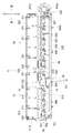
- FIG. 4 is a sectional view taken along line AA of the fertilizer applicator shown in FIGS. 2 and 3. It is a plane sectional view of a fertilizer application device. It is a disassembled perspective view of a 1st hopper and a spacer hopper.
- FIG. 1 shows a rice transplanter 1 provided with a fertilizer application device 5.
- a schematic structure of the rice transplanter 1 will be described.
- the left side of the traveling device 2 in the forward direction is simply referred to as “left” or “left side”
- the right side in the forward direction is also simply referred to as “right” or “right side”.
- the rice transplanter 1 includes a traveling device 2, a lifting device 3, and a seedling planting device 4.
- the traveling device 2 includes a traveling body 2a, a pair of left and right front wheels 2b, 2b and a pair of left and right rear wheels 2c, 2c supporting the traveling body 2a, and an engine 2d mounted on a front portion of the traveling body 2a. I have. By transmitting the power from the engine 2d to the rear transmission case 2e and driving the front wheels 2b, 2b and the rear wheels 2c, 2c, the traveling body 2a is configured to travel forward and backward.
- the traveling device 2 includes a control unit (not shown).
- the control unit is configured to control each component of the rice transplanter 1 based on a signal from a sensor or the like provided in each unit of the rice transplanter 1.
- the traveling device 2 also includes a work step (vehicle cover) 2f for boarding the operator, a front bonnet 2g for covering the engine 2d, and a driving operation unit 2h.
- the work step 2f is provided on the upper surface side of the front part and the center part of the traveling body 2a.
- the front bonnet 2g is arranged above a front portion of the work step 2f, and an engine 2d is provided therein.
- the driving operation unit 2h is disposed on the rear upper surface side of the front bonnet 2g, and is a not-shown operation for operating the steering handle 2i, the main traveling speed change lever for operating the traveling speed, and the seedling planting device 4. And a lever.
- a control seat 2j is arranged behind the front bonnet 2g on the upper surface of the work step 2f.
- the lifting device 3 is disposed behind the traveling device 2, and the seedling planting device 4 is connected to the traveling device 2 via the lifting device 3 so as to be able to move up and down.
- the seedling planting device 4 includes a seedling mounting table 4a on which a seedling mat is placed, and a planting section 4b for scraping and planting one seedling from the seedling mat.
- the planting section 4b is arranged below the seedling mounting table 4a.
- the planting unit 4b includes a rotating planting claw 4c, and the planting claw 4c is revolved to scrape one plant of seedlings from a seedling mat located at the lower end of the seedling mounting table 4a. And plant it in the field.
- the fertilizer application device 5 supplies fertilizer to a field at the same time as planting of the seedlings by the seedling planting device 4.
- the fertilizer application device 5 is arranged behind the control seat 2j and in front of the seedling planting device 4.
- the fertilizer applicator 5 includes a fertilizer application frame 50, a first fertilizer 51, a second fertilizer 52, and a fertilizer drive unit 53. Further, the fertilizer applicator 5 includes a lower fertilizer applicator 54, a first rotation mechanism 55, and a second rotation mechanism 56.
- the fertilizer application frame 50 includes a pair of left and right support plates 501, an upper frame 502 connecting the upper portions of the support plates 501 to each other, a pair of front and rear lower frames 503 connecting the lower portions of the support plates 501 to each other, and a lower frame. And a connection frame 504 that connects the 503 with each other.
- the fertilizer application frame 50 is fixed to the traveling device 2 behind the control seat 2j.
- the fertilizer drive unit 53 transmits the power transmitted from the engine 2d.
- the fertilizing drive unit 53 is provided at a front part of the fertilizing frame 50.
- the fertilizer drive unit 53 includes a first transmission shaft 531, a drive case 532, and a second transmission shaft 533.
- the first transmission shaft 531 has one end connected to the transmission case 2e (not shown in FIG. 2) and the other end connected to the drive case 532.
- the first transmission shaft 531 transmits the power transmitted from the transmission case 2e to the drive case 532.
- the drive case 532 shifts the transmitted power and transmits the power to the second transmission shaft 533.
- the drive case 532 incorporates gears and the like for shifting the power.
- the drive case 532 is disposed on the right side in the left-right direction.
- the transmission case 2e is also disposed rightward in the left-right direction, and the drive case 532 is disposed above the transmission case 2e.
- the second transmission shaft 533 transmits the power shifted in the drive case 532.
- One end of the second transmission shaft 533 is connected to the drive case 532, and the other end protrudes rearward of the drive case 532.
- the first fertilizer 51 and the second fertilizer 52 are arranged side by side in the left-right direction, and the first fertilizer 51 is arranged on the right and the second fertilizer 52 is arranged on the left.
- the first fertilizer 51 and the second fertilizer 52 are disposed above the fertilizer driving unit 53.
- the first fertilizer 51 includes a first hopper 511, a power transmission mechanism 512, a first input shaft 513, a first lid 514, and a first feeding portion 515.
- the first fertilizer 51 has four first hoppers 511 arranged in parallel in the left-right direction. Further, the first fertilizer applicator 51 is provided with a spacer hopper 516 between the left two first hoppers 511 of the four first hoppers 511.
- ⁇ Fertilizer is stored in the first hopper 511.
- the upper and lower parts of the first hopper 511 are open.
- the lower part of the first hopper 511 is formed in a funnel shape.
- First cutouts 511a are formed in the upper portions of the side surfaces on which the first hoppers 511 face each other, and the first cutouts 511a allow the internal spaces to communicate with each other.
- a first cutout portion 511a is also formed on an upper portion of a side surface of the first hopper 511 facing the spacer hopper 516.
- a first communication hole 511b for communicating the internal space with the outside is formed on the right side surface of the first hopper 511 located on the rightmost side.
- the spacer hopper 516 and the first hoppers 511 on both sides thereof are connected by bolts and nuts.
- the adjacent first hoppers 511 are also connected by bolts and nuts.
- the width of the spacer hopper 516 in the left-right direction is smaller than the width of the first hopper 511 in the left-right direction, and wider than the interval between the adjacent first hoppers 511.
- the upper portion of the spacer hopper 516 is open, and the lower portion of the spacer hopper 516 is closed.
- the spacer hopper 516 has a U shape in a side view.
- third cutout portions 516a are formed on the left and right side surfaces of the spacer hopper 516, respectively.
- the third cutout portion 516a is formed at a position corresponding to the first cutout portion 511a of the adjacent first hopper 511, and the spacer hopper 516 and the internal space of the first hopper 511 communicate with each other. That is, the inside of the first hopper 511 for two rows in which the spacer hopper 516 is provided is communicated by the spacer hopper 516.
- the power transmission mechanism 512 transmits the power from the fertilizer drive unit 53 to the first input shaft 513.
- the power transmission mechanism 512 is arranged behind the fertilizer application drive unit 53.
- the second transmission shaft 533 of the fertilizer drive unit 53 is connected to the power transmission mechanism 512.
- the first input shaft 513 is connected to the power transmission mechanism 512 to transmit power.
- the first input shaft 513 is inserted into the power transmission mechanism 512, and extends left and right from the power transmission mechanism 512.
- the first lid 514 covers the upper parts of the first hopper 511 and the spacer hopper 516, and closes the opened upper parts of the first hopper 511 and the spacer hopper 516.
- the first feeding units 515 are disposed below the first hopper 511, respectively, and feed the fertilizer stored in the first hopper 511 by a predetermined amount.
- the first feeding portion 515 includes an upper receiving portion 515a, a feeding mechanism 515b, and a lower receiving portion 515c.
- the upper storage section 515a receives the fertilizer dropped from the first hopper 511.
- the upper and lower parts of the upper storage part 515a are open, and the upper part of the opened upper storage part 515a is connected to the lower part of the opened first hopper 511.
- the feeding mechanism 515b feeds out a predetermined amount of fertilizer in the upper storage portion 515a.
- the feeding mechanism 515b is a power transmitted via a driving bevel gear 515d fixed to the first input shaft 513, a driven bevel gear 515e meshing with the driving bevel gear 515d, and a feeding shaft 515f fixed to the driven bevel gear 515e.
- the lower housing part 515c receives the fertilizer supplied via the feeding mechanism 515b.
- the lower housing part 515c is disposed below the feeding mechanism 515b.
- the upper and lower parts of the lower housing part 515c are open, and the upper part of the opened lower housing part 515c is connected to the feeding mechanism 515b.
- the lower accommodating portion 515c is formed in a funnel shape, and a lower portion of the opened lower accommodating portion 515c is connected to a connection pipe 541a described later.
- the second fertilizer 52 includes a second hopper 521, a second input shaft 523, a second lid 524, and a second feeding portion 525.
- the second fertilizer 52 includes a second hopper 521 for five rows arranged in the left-right direction.
- the upper and lower parts of the second hopper 521 are open.
- the lower part of the second hopper 521 is formed in a funnel shape.
- a second notch (not shown) is formed in the upper part of the side surface on the side where the second hoppers 521 face each other, and the second notch allows the internal spaces to communicate with each other.
- a second communication hole 521b for communicating the internal space with the outside is formed on the left side surface of the second hopper 521 located on the leftmost side.
- the configuration of the second hopper 521 is substantially the same as the configuration of the first hopper 511, and the other description is omitted.
- the second input shaft 523 transmits power from the power transmission mechanism 512.
- the second input shaft 523 is disposed on the same axis as the first input shaft 513, and is connected to the first input shaft 513 via the connecting portion 522.
- the second lid 524 covers the upper part of the second hopper 521 and closes the upper part of the opened second hopper 521.
- the second feeding units 525 are provided below the second hopper 521, respectively, and feed the fertilizer stored in the second hopper 521 by a predetermined amount.
- the second feeding portion 525 is driven by power transmitted by the second input shaft 523.
- the configuration of the second feeding section 525 is substantially the same as the configuration of the first feeding section 515, and thus the description is omitted.
- the lower fertilizer 54 supplies fertilizer fed from the first fertilizer 51 and the second fertilizer 52 to the field.
- the lower fertilizer applicator 54 includes a transport section 541, a fertilizer section 542, and a blower section 543.
- the transport unit 541 transports the fertilizer that is fed from the first feeding unit 515 and the second feeding unit 525.
- the transfer section 541 includes a connection pipe 541a and a transfer hose 541b.
- the connection pipe 541a is a tubular member extending in the front-rear direction, and the lower ends of the first feeding portion 515 and the second feeding portion 525 are connected.
- One end of the transfer hose 541b is connected to the rear end of the connection pipe 541a, and the other end extends to the vicinity of the planting section 4b and is connected to the fertilizer section 542.
- the fertilizer application section 542 is for dropping fertilizer into the field.
- the other end of the transfer hose 541b is connected to the fertilizer 542.
- the blower 543 blows air into the transporter 541 to assist in transporting the fertilizer.
- the blower 543 includes a blower 543a and a blower pipe 543b.
- the blower 543a blows air into the blower pipe 543b, and is arranged at the left end of the fertilizer application frame 50.
- the blower tube 543b is a tubular member extending in the left-right direction, and is connected to a front end of the connection tube 541a.
- One end of the blower tube 543b is connected to the blower 543a.
- the other end of the blower tube 543b is closed. Thereby, the wind supplied from the blower 543a is sent to the connection pipe 541a.
- the first turning mechanism 55 supports the first fertilizer 51 so as to be rotatable up and down with respect to the fertilizing frame 50.
- the first rotation mechanism 55 includes a first bracket 551 and a first rotation shaft 552.
- the first bracket 551 is fixed to the right end of the first fertilizer 51.
- the first bracket 551 is a plate-like member extending in the up-down direction.
- the upper end is fixed to the lower part of the first hopper 511, and the lower end is connected to the fertilizer application frame 50.
- the first rotating shaft 552 is supported by the right end of the fertilizer application frame 50 with the front-rear direction being the axial direction.
- the first fertilizer applicator 51 is capable of changing its posture to a driving posture located above the fertilization driving unit 53 shown in FIG. 2 and a standing posture that rotates upward about the first rotation shaft 552.
- the first cutout portion 511a and the third cutout portion 516a are formed on the side surface on the side where the first hopper 511 and the spacer hopper 516 are opposed to each other, and the internal spaces thereof are communicated with each other.
- the fertilizer in the upper first hopper 511 and the spacer hopper 516 passes through the first cutout portion 511a and the third cutout portion 516a, and passes through the first cutout portion 511a and the third cutout portion 516a. It is discharged outside through one communication hole 511b.
- the second rotation mechanism 56 supports the second fertilizer 52 so as to be rotatable vertically with respect to the fertilizer application frame 50.
- the second rotation mechanism 56 includes a second bracket 561 and a second rotation shaft 562.
- the second bracket 561 is fixed to the left end of the second fertilizer 52.
- the second bracket 561 is a plate-like member extending in the vertical direction.
- the upper end is fixed to the lower part of the second hopper 521, and the lower end is connected to the fertilizer application frame 50.
- the second rotating shaft 562 is supported by the left end of the fertilizing frame 50 with the front-rear direction being the axial direction.
- the second fertilizer applicator 52 is capable of changing its posture to a driving posture located above the fertilization driving unit 53 shown in FIG. 2 and an upright posture that rotates upward about the second rotation shaft 562.
- the second cutouts are formed on the side surfaces on the side where the second hoppers 521 face each other, and the internal spaces communicate with each other, and the posture of the second fertilizer 52 is changed to the standing posture.
- the fertilizer in the upper second hopper 521 is discharged to the outside from the second communication hole 521b through the second cutout.
- the spacer hopper 516 is provided between the left two first hoppers 511 of the four first hoppers 511 has been described, but the position at which the spacer hopper 516 is provided therebetween. Is not limited to this.
- the spacer hopper 516 may be provided between the first two hoppers 511 on the right side of the four first hoppers 511 and the middle two of the four first hoppers 511. It may be provided between the first hoppers 511.
- the first fertilizer 51 has an example having four first hoppers 511 and a spacer hopper 516
- the second fertilizer 52 has an example having five second hoppers 521.
- the first fertilizer 51 may have five first hoppers 511 and a spacer hopper 516
- the second fertilizer 52 may have six second hoppers 521.
- the first fertilizer 51 may have the first hopper 511 and the spacer hopper 516 for six rows
- the second fertilizer 52 may have the second hopper 521 for seven rows.
Landscapes
- Life Sciences & Earth Sciences (AREA)
- Soil Sciences (AREA)
- Environmental Sciences (AREA)
- Fertilizing (AREA)
- Transplanting Machines (AREA)
Abstract
田植機1に備えられる施肥装置5であって、第1施肥機51と、第2施肥機52と、第1施肥機51及び第2施肥機52に動力を伝達する施肥駆動部53とを備え、第1施肥機51は、4条分の第1ホッパー511を有し、施肥駆動部53の上方に位置する駆動姿勢と第1回動軸552を中心として上方に回動する起立姿勢とに姿勢変更自在に構成され、第2施肥機52は、5条分のホッパーを有し、施肥駆動部53は、走行装置2のミッションケース2eからの動力を伝達する駆動ケース532を有し、第1施肥機51は、4条分の第1ホッパー511のうち何れか2条分の第1ホッパー511の間に設けられる間座ホッパー516を有し、第1施肥機51が駆動姿勢のとき、間座ホッパー516が駆動ケース532の上方に位置する。
Description
本発明は、田植機に備えられ、ホッパー内の肥料を所定量ずつ圃場に供給する施肥装置に関する。
下記特許文献1には、施肥装置付きの苗植機(田植機)が開示されている。特許文献1の施肥装置では、肥料を収容する施肥タンクが9条分設けられており、施肥タンクは、5条分の中央施肥タンクと2条分の左右施肥タンクとにより構成されている。使用状態では左右施肥タンクを機体左右方向に突出させているが、路上を運搬する際の制約のため、非使用状態では、左右施肥タンクを回動させて運転席近くへ位置変更させ、施肥装置の左右方向の幅を小さくしなければならない。使用状態と非使用状態を切り替えることは作業者の労力となるため、この労力を少なくすることが望まれる。
そのため、使用状態で機体左右方向に突出しないように、各施肥タンクの幅を小さくして施肥装置の左右方向の幅を小さくすることが考えられる。しかしながら、施肥装置の左右方向の幅を小さくするうえで、施肥タンクのみならずその他の構成部品を含めた左右方向の重量バランスを考慮したレイアウトを検討する必要がある。
そこで、本発明は上記課題に鑑み、左右方向の重量バランスを考慮しつつ、使用状態における左右方向の幅を小さくできる施肥装置を提供することを目的とする。
本発明の施肥装置は、田植機に備えられ、ホッパー内の肥料を所定量ずつ圃場に供給する施肥装置であって、
機体左右方向の一方側に配置される第1施肥機と、機体左右方向の他方側に配置される第2施肥機と、前記第1施肥機及び前記第2施肥機に動力を伝達する施肥駆動部とを備え、
前記第1施肥機は、機体左右方向に並設された4条分のホッパーを有し、前記施肥駆動部の上方に位置する駆動姿勢と機体左右方向の一方側の回動軸を中心として上方に回動する起立姿勢とに姿勢変更自在に構成され、
前記第2施肥機は、機体左右方向に並設された5条分のホッパーを有し、前記施肥駆動部の上方に位置する駆動姿勢と機体左右方向の他方側の回動軸を中心として上方に回動する起立姿勢とに姿勢変更自在に構成され、
前記施肥駆動部は、前記田植機の走行装置のミッションケースからの動力を伝達する駆動ケースを有し、
前記第1施肥機は、前記4条分のホッパーのうち何れか2条分のホッパーの間に設けられる間座ホッパーを有し、
前記第1施肥機が駆動姿勢のとき、前記間座ホッパーが前記駆動ケースの上方に位置するものである。
機体左右方向の一方側に配置される第1施肥機と、機体左右方向の他方側に配置される第2施肥機と、前記第1施肥機及び前記第2施肥機に動力を伝達する施肥駆動部とを備え、
前記第1施肥機は、機体左右方向に並設された4条分のホッパーを有し、前記施肥駆動部の上方に位置する駆動姿勢と機体左右方向の一方側の回動軸を中心として上方に回動する起立姿勢とに姿勢変更自在に構成され、
前記第2施肥機は、機体左右方向に並設された5条分のホッパーを有し、前記施肥駆動部の上方に位置する駆動姿勢と機体左右方向の他方側の回動軸を中心として上方に回動する起立姿勢とに姿勢変更自在に構成され、
前記施肥駆動部は、前記田植機の走行装置のミッションケースからの動力を伝達する駆動ケースを有し、
前記第1施肥機は、前記4条分のホッパーのうち何れか2条分のホッパーの間に設けられる間座ホッパーを有し、
前記第1施肥機が駆動姿勢のとき、前記間座ホッパーが前記駆動ケースの上方に位置するものである。
本発明の施肥装置において、第1施肥機は4条分のホッパーを有し、第2施肥機は5条分のホッパーを有しているため、ホッパー内に肥料が収容される使用状態では第2施肥機が第1施肥機よりも重くなる傾向がある。しかし、本発明では、第1施肥機は間座ホッパーを有し、この間座ホッパーの下方に重量物である駆動ケースが配置されているため、左右方向の重量バランスを向上できる。その結果、本発明の施肥装置は、左右方向の重量バランスを考慮しつつ、各ホッパーの幅を小さくして使用状態における施肥装置の左右方向の幅を小さくできる。
本発明において、前記間座ホッパーが間に設けられる前記2条分のホッパーは、前記間座ホッパーによって内部が連通されることが好ましい。この構成によれば、隣り合う2条分のホッパーの間を肥料が行き来することができるため、メンテナンス作業が容易となる。
以下に、本発明の実施形態について図面を参照しながら説明する。
図1は、施肥装置5を備える田植機1を示している。まず、田植機1の概略構造について説明する。なお、以下の説明では、走行装置2の前進方向に向かって左側を単に「左」又は「左側」と称し、同じく前進方向に向かって右側を単に「右」又は「右側」と称する。
本実施形態に係る田植機1は、走行装置2と、昇降装置3と、苗植付装置4とを備えている。
走行装置2は、走行機体2aと、走行機体2aを支持する左右一対の前輪2b,2b及び左右一対の後輪2c,2cと、走行機体2aの前部に搭載されるエンジン2dとを備えている。エンジン2dからの動力を後方のミッションケース2eに伝達して、前輪2b,2b及び後輪2c,2cを駆動させることにより、走行機体2aが前後進走行するように構成されている。また、走行装置2は、不図示の制御部を備えている。制御部は、田植機1の各部に備えられたセンサ等の信号に基づいて、田植機1の各構成を制御するように構成されている。
また、走行装置2は、オペレータ搭乗用の作業ステップ(車体カバー)2fと、エンジン2dを覆うフロントボンネット2gと、運転操作部2hとを備えている。作業ステップ2fは、走行機体2aの前部及び中央部の上面側に設けられている。フロントボンネット2gは、作業ステップ2fの前部の上方に配置され、その内部にエンジン2dが設けられている。運転操作部2hは、フロントボンネット2gの後部上面側に配置され、操向ハンドル2iと、走行速度を操作するための走行主変速レバーと、苗植付装置4を操作するための不図示の作業レバーとを備えている。作業ステップ2fの上面のうちフロントボンネット2gの後方には、操縦座席2jが配置されている。
昇降装置3は、走行装置2の後方に配置され、走行装置2には、昇降装置3を介して苗植付装置4が昇降可能に連結されている。
苗植付装置4は、苗マットが載せられる苗載台4aと、苗マットから一株分の苗を掻き取って植え付ける植付部4bとを備えている。植付部4bは、苗載台4aの下方に配置されている。植付部4bは、回転する植付爪4cを備えており、植付爪4cは、公転されることで、苗載台4aの下端部に位置する苗マットから一株分の苗を掻き取って、圃場に植え付ける。
次いで、施肥装置5について説明する。施肥装置5は、苗植付装置4による苗の植え付けと同時に、肥料を圃場に供給するものである。
施肥装置5は、操縦座席2jの後方かつ苗植付装置4の前方に配置されている。施肥装置5は、施肥フレーム50と、第1施肥機51と、第2施肥機52と、施肥駆動部53とを備えている。さらに、施肥装置5は、下部施肥機54と、第1回動機構55と、第2回動機構56とを備えている。
施肥フレーム50は、左右一対に立設される支持板501と、支持板501の上部を互いに連結する上フレーム502と、支持板501の下部を互いに連結する前後一対の下フレーム503と、下フレーム503を互いに連結する連結フレーム504とを備えている。施肥フレーム50は、操縦座席2jの後方にて走行装置2に固定される。
施肥駆動部53は、エンジン2dから伝達された動力を伝達するものである。施肥駆動部53は、施肥フレーム50の前部に設けられている。施肥駆動部53は、第1伝動軸531と、駆動ケース532と、第2伝動軸533とを備えている。
第1伝動軸531は、一端がミッションケース2e(図2では不図示)に連結され、他端が駆動ケース532に連結されている。第1伝動軸531は、ミッションケース2eから伝達された動力を駆動ケース532に伝達する。
駆動ケース532は、伝達される動力を変速して第2伝動軸533に伝達する。駆動ケース532には、動力を変速するための歯車等が内蔵されている。駆動ケース532は、左右方向の右寄りに配置されている。ミッションケース2eも左右方向の右寄りに配置されており、駆動ケース532は、ミッションケース2eの上方に配置されている。
第2伝動軸533は、駆動ケース532において変速された動力を伝達するものである。第2伝動軸533は、一端が駆動ケース532に連結され、他端が駆動ケース532の後方に向かって突出されている。
第1施肥機51と第2施肥機52は、左右方向に並べて配置されており、第1施肥機51が右側、第2施肥機52が左側に配置されている。第1施肥機51及び第2施肥機52は、施肥駆動部53よりも上側に配置されている。
第1施肥機51は、第1ホッパー511と、動力伝達機構512と、第1入力軸513と、第1蓋514と、第1繰り出し部515とを備えている。
第1施肥機51は、左右方向に並設された4条分の第1ホッパー511を備えている。さらに、第1施肥機51は、4条分の第1ホッパー511のうち左側の2条分の第1ホッパー511の間に間座ホッパー516を備えている。
第1ホッパー511には、肥料が収容される。第1ホッパー511の上部及び下部は開口されている。第1ホッパー511の下部は、漏斗状に形成されている。第1ホッパー511が互いに対向する側の側面の上部には、それぞれ第1切り欠き部511aが形成され、この第1切り欠き部511aにより互いの内部空間が連通される。また、間座ホッパー516に対向する第1ホッパー511の側面の上部にも、第1切り欠き部511aが形成されている。また、最も右側に位置する第1ホッパー511の右側面には、内部空間と外部とを連通する第1連通孔511bが形成されている。
間座ホッパー516とその両側の第1ホッパー511とは、ボルト及びナットにより連結されている。また、隣接する第1ホッパー511同士もボルト及びナットにより連結されている。間座ホッパー516の左右方向の幅は、第1ホッパー511の左右方向の幅よりも狭く、かつ隣接する第1ホッパー511同士の間隔よりも広くなっている。
間座ホッパー516の上部は開口され、間座ホッパー516の下部は閉塞されている。間座ホッパー516は、側面視でU字状をしている。また、間座ホッパー516の左右の側面には、それぞれ第3切り欠き部516aが形成されている。第3切り欠き部516aは、隣接する第1ホッパー511の第1切り欠き部511aに対応する位置に形成されており、間座ホッパー516と第1ホッパー511の内部空間は連通されている。すなわち、間座ホッパー516が間に設けられる2条分の第1ホッパー511は、間座ホッパー516によって内部が連通されている。
間座ホッパー516の内底面516bの左右両端部は、第3切り欠き部516aの下端部と一致している。内底面516bは、左右中央部が左右両端部よりも上方に突出している。また、間座ホッパー516の内底面516bは、第1ホッパー511の内底面よりも上方に位置している。これにより、間座ホッパー516内の肥料は、隣接する第1ホッパー511内に振り分けられる。間座ホッパー516の下方の空間には、動力伝達機構512、及び施肥駆動部53の駆動ケース532が配置される。
動力伝達機構512は、施肥駆動部53からの動力を第1入力軸513に伝達するものである。動力伝達機構512は、施肥駆動部53の後方に配置される。動力伝達機構512には、施肥駆動部53の第2伝動軸533が連結される。
第1入力軸513は、動力伝達機構512と連結されて動力を伝達するものである。第1入力軸513は、動力伝達機構512に挿通され、動力伝達機構512から左右に延設されている。
第1蓋514は、第1ホッパー511及び間座ホッパー516の上部を覆い、開口された第1ホッパー511及び間座ホッパー516の上部を閉塞する。
第1繰り出し部515は、第1ホッパー511の下部にそれぞれ配設され、第1ホッパー511に収容された肥料を所定量ずつ繰り出すものである。第1繰り出し部515は、上側収容部515aと、繰り出し機構515bと、下側収容部515cとを備えている。
上側収容部515aは、第1ホッパー511から落下した肥料を受け入れるものである。上側収容部515aの上部及び下部は開口されており、開口された上側収容部515aの上部は、開口された第1ホッパー511の下部に接続されている。
繰り出し機構515bは、上側収容部515aの肥料を所定量ずつ繰り出すものである。繰り出し機構515bは、第1入力軸513に固設される駆動ベベルギヤ515dと、駆動ベベルギヤ515dと噛合する従動ベベルギヤ515eと、従動ベベルギヤ515eに固設される繰り出し軸515fとを介して伝達される動力により駆動される。
下側収容部515cは、繰り出し機構515bを介して供給される肥料を受け入れるものである。下側収容部515cは、繰り出し機構515bの下方に配置される。下側収容部515cの上部及び下部は開口されており、開口された下側収容部515cの上部は、繰り出し機構515bに接続されている。下側収容部515cは、漏斗状に形成され、開口された下側収容部515cの下部は、後述する接続管541aに接続されている。
第2施肥機52は、第2ホッパー521と、第2入力軸523と、第2蓋524と、第2繰り出し部525とを備えている。
第2施肥機52は、左右方向に並設された5条分の第2ホッパー521を備えている。第2ホッパー521の上部及び下部は開口されている。第2ホッパー521の下部は、漏斗状に形成されている。第2ホッパー521が互いに対向する側の側面の上部には、それぞれ第2切り欠き部(図示していない)が形成され、この第2切り欠き部により互いの内部空間が連通される。また、最も左側に位置する第2ホッパー521の左側面には、内部空間と外部とを連通する第2連通孔521bが形成されている。第2ホッパー521の構成は、第1ホッパー511の構成と略同様であるため、その他の説明を省略する。
第2入力軸523は、動力伝達機構512からの動力を伝達するものである。第2入力軸523は、第1入力軸513と同一軸線上に配置され、連結部522を介して第1入力軸513と連結される。
第2蓋524は、第2ホッパー521の上部を覆い、開口された第2ホッパー521の上部を閉塞する。
第2繰り出し部525は、第2ホッパー521の下部にそれぞれ配設され、第2ホッパー521に収容された肥料を所定量ずつ繰り出すものである。第2繰り出し部525は、第2入力軸523により伝達される動力により駆動される。第2繰り出し部525の構成は、第1繰り出し部515の構成と略同様であるため、説明を省略する。
下部施肥機54は、第1施肥機51及び第2施肥機52から繰り出される肥料を圃場に供給するものである。下部施肥機54は、搬送部541と、施肥部542と、送風部543とを備えている。
搬送部541は、第1繰り出し部515及び第2繰り出し部525より繰り出される肥料を搬送するものである。搬送部541は、接続管541a及び搬送ホース541bを備えている。接続管541aは、前後方向に延びる筒状部材であり、第1繰り出し部515及び第2繰り出し部525の下端が接続されている。搬送ホース541bは、一端が接続管541aの後端に接続され、他端が植付部4bの近傍まで延びて施肥部542に接続される。
施肥部542は、圃場に肥料を落下させるものである。施肥部542は、搬送ホース541bの他端が接続されている。
送風部543は、搬送部541内に送風して、肥料の搬送を補助するものである。送風部543は、ブロワ543a及び送風管543bを備えている。ブロワ543aは、送風管543b内に送風するものであり、施肥フレーム50の左端部に配置されている。このように、左右方向において駆動ケース532の反対側にブロワ543aを配置することで、施肥装置5の左右方向の重量バランスが良好となる。送風管543bは、左右方向に延びる筒状部材であり、接続管541aの前端が接続されている。送風管543bの一端はブロワ543aに接続されている。一方、送風管543bの他端は閉塞されている。これにより、ブロワ543aから供給された風は、接続管541aに送られる。
第1回動機構55は、第1施肥機51を施肥フレーム50に対して上下方向に回動可能に支持する。第1回動機構55は、第1ブラケット551及び第1回動軸552を備えている。
第1ブラケット551は、第1施肥機51の右端部に固定されている。第1ブラケット551は、上下方向に延びる板状部材であり、上端部は第1ホッパー511の下部に固定され、下端部は施肥フレーム50に連結されている。
第1回動軸552は、前後方向を軸線方向として施肥フレーム50の右端部に支持されている。第1施肥機51は、図2に示す施肥駆動部53の上方に位置する駆動姿勢と、第1回動軸552を中心として上方に回動する起立姿勢とに姿勢変更可能となっている。前述のように、第1ホッパー511及び間座ホッパー516が互いに対向する側の側面には、それぞれ第1切り欠き部511a及び第3切り欠き部516aが形成され、互いの内部空間が連通されており、第1施肥機51が起立姿勢に姿勢変更された場合、上側の第1ホッパー511及び間座ホッパー516内の肥料は、第1切り欠き部511a及び第3切り欠き部516aを通って第1連通孔511bから外部へ排出される。
第2回動機構56は、第2施肥機52を施肥フレーム50に対して上下方向に回動可能に支持する。第2回動機構56は、第2ブラケット561及び第2回動軸562を備えている。
第2ブラケット561は、第2施肥機52の左端部に固定されている。第2ブラケット561は、上下方向に延びる板状部材であり、上端部は第2ホッパー521の下部に固定され、下端部は施肥フレーム50に連結されている。
第2回動軸562は、前後方向を軸線方向として施肥フレーム50の左端部に支持されている。第2施肥機52は、図2に示す施肥駆動部53の上方に位置する駆動姿勢と、第2回動軸562を中心として上方に回動する起立姿勢とに姿勢変更可能となっている。前述のように、第2ホッパー521が互いに対向する側の側面には、それぞれ第2切り欠き部が形成され、互いの内部空間が連通されており、第2施肥機52が起立姿勢に姿勢変更された場合、上側の第2ホッパー521内の肥料は、第2切り欠き部を通って第2連通孔521bから外部へ排出される。
[他の実施形態]
前述の実施形態では、4条分の第1ホッパー511のうち左側の2条分の第1ホッパー511の間に間座ホッパー516を設ける例を示したが、間座ホッパー516を間に設ける位置はこれに限定されない。間座ホッパー516は、4条分の第1ホッパー511のうち右側の2条分の第1ホッパー511の間に設けてもよく、4条分の第1ホッパー511のうち真ん中の2条分の第1ホッパー511の間に設けてもよい。
前述の実施形態では、4条分の第1ホッパー511のうち左側の2条分の第1ホッパー511の間に間座ホッパー516を設ける例を示したが、間座ホッパー516を間に設ける位置はこれに限定されない。間座ホッパー516は、4条分の第1ホッパー511のうち右側の2条分の第1ホッパー511の間に設けてもよく、4条分の第1ホッパー511のうち真ん中の2条分の第1ホッパー511の間に設けてもよい。
前述の実施形態では、第1施肥機51は、4条分の第1ホッパー511と間座ホッパー516を有し、第2施肥機52は、5条分の第2ホッパー521を有する例を示したが、これに限定されない。例えば、第1施肥機51が5条分の第1ホッパー511と間座ホッパー516を有し、第2施肥機52が6条分の第2ホッパー521を有するようにしてもよい。また、第1施肥機51が6条分の第1ホッパー511と間座ホッパー516を有し、第2施肥機52が7条分の第2ホッパー521を有するようにしてもよい。
以上、本発明の実施形態について図面に基づいて説明したが、具体的な構成は、これらの実施形態に限定されるものでないと考えられるべきである。本発明の範囲は、上記した実施形態の説明だけではなく特許請求の範囲によって示され、さらに特許請求の範囲と均等の意味および範囲内でのすべての変更が含まれる。
1 田植機
2 走行装置
2a 走行機体
2e ミッションケース
4 苗植付装置
5 施肥装置
51 第1施肥機
511 第1ホッパー
516 間座ホッパー
52 第2施肥機
521 第2ホッパー
53 施肥駆動部
532 駆動ケース
55 第1回動機構
552 第1回動軸
56 第2回動機構
562 第2回動軸
2 走行装置
2a 走行機体
2e ミッションケース
4 苗植付装置
5 施肥装置
51 第1施肥機
511 第1ホッパー
516 間座ホッパー
52 第2施肥機
521 第2ホッパー
53 施肥駆動部
532 駆動ケース
55 第1回動機構
552 第1回動軸
56 第2回動機構
562 第2回動軸
Claims (2)
- 田植機に備えられ、ホッパー内の肥料を所定量ずつ圃場に供給する施肥装置であって、
機体左右方向の一方側に配置される第1施肥機と、機体左右方向の他方側に配置される第2施肥機と、前記第1施肥機及び前記第2施肥機に動力を伝達する施肥駆動部とを備え、
前記第1施肥機は、機体左右方向に並設された4条分のホッパーを有し、前記施肥駆動部の上方に位置する駆動姿勢と機体左右方向の一方側の回動軸を中心として上方に回動する起立姿勢とに姿勢変更自在に構成され、
前記第2施肥機は、機体左右方向に並設された5条分のホッパーを有し、前記施肥駆動部の上方に位置する駆動姿勢と機体左右方向の他方側の回動軸を中心として上方に回動する起立姿勢とに姿勢変更自在に構成され、
前記施肥駆動部は、前記田植機の走行装置のミッションケースからの動力を伝達する駆動ケースを有し、
前記第1施肥機は、前記4条分のホッパーのうち何れか2条分のホッパーの間に設けられる間座ホッパーを有し、
前記第1施肥機が駆動姿勢のとき、前記間座ホッパーが前記駆動ケースの上方に位置する、施肥装置。 - 前記間座ホッパーが間に設けられる前記2条分のホッパーは、前記間座ホッパーによって内部が連通される、請求項1に記載の施肥装置。
Priority Applications (1)
| Application Number | Priority Date | Filing Date | Title |
|---|---|---|---|
| CN201980049022.8A CN112469265B (zh) | 2018-07-27 | 2019-06-19 | 施肥装置 |
Applications Claiming Priority (2)
| Application Number | Priority Date | Filing Date | Title |
|---|---|---|---|
| JP2018-141080 | 2018-07-27 | ||
| JP2018141080A JP7022026B2 (ja) | 2018-07-27 | 2018-07-27 | 施肥装置 |
Publications (1)
| Publication Number | Publication Date |
|---|---|
| WO2020021917A1 true WO2020021917A1 (ja) | 2020-01-30 |
Family
ID=69182227
Family Applications (1)
| Application Number | Title | Priority Date | Filing Date |
|---|---|---|---|
| PCT/JP2019/024275 Ceased WO2020021917A1 (ja) | 2018-07-27 | 2019-06-19 | 施肥装置 |
Country Status (3)
| Country | Link |
|---|---|
| JP (1) | JP7022026B2 (ja) |
| CN (1) | CN112469265B (ja) |
| WO (1) | WO2020021917A1 (ja) |
Cited By (1)
| Publication number | Priority date | Publication date | Assignee | Title |
|---|---|---|---|---|
| WO2025096878A1 (en) | 2023-11-02 | 2025-05-08 | Capstan Therapeutics, Inc. | Rna for in vivo transfection with increased expression |
Families Citing this family (1)
| Publication number | Priority date | Publication date | Assignee | Title |
|---|---|---|---|---|
| CN114158331B (zh) * | 2021-12-19 | 2025-08-15 | 常州常发重工科技有限公司 | 一种水田作业车 |
Citations (2)
| Publication number | Priority date | Publication date | Assignee | Title |
|---|---|---|---|---|
| JP2011193733A (ja) * | 2010-03-17 | 2011-10-06 | Yanmar Co Ltd | 施肥装置付き乗用田植機 |
| JP2017175971A (ja) * | 2016-03-29 | 2017-10-05 | ヤンマー株式会社 | 粒状物繰出装置及びその装置を載設した農作業機 |
Family Cites Families (8)
| Publication number | Priority date | Publication date | Assignee | Title |
|---|---|---|---|---|
| JPH10304721A (ja) * | 1997-05-06 | 1998-11-17 | Yanmar Agricult Equip Co Ltd | 農作業装置 |
| JP5078843B2 (ja) * | 2008-11-04 | 2012-11-21 | 八鹿鉄工株式会社 | 乗用田植機 |
| JP5189523B2 (ja) * | 2009-02-18 | 2013-04-24 | 八鹿鉄工株式会社 | 施肥装置 |
| KR101242095B1 (ko) * | 2008-12-03 | 2013-03-11 | 요카 인더스트리 가부시키가이샤 | 시비 장치 |
| JP2011097848A (ja) * | 2009-11-04 | 2011-05-19 | Yanmar Co Ltd | 施肥装置及びそれを載設した乗用田植機 |
| TWI511659B (zh) * | 2009-11-04 | 2015-12-11 | Yanmar Co Ltd | A fertilizer applicator and a take-in transplanter equipped with the device |
| JP2016036271A (ja) * | 2014-08-06 | 2016-03-22 | ヤンマー株式会社 | 粒状体散布装置、及びこれを備えた散布作業車 |
| JP2016036272A (ja) * | 2014-08-06 | 2016-03-22 | ヤンマー株式会社 | 粒状体散布装置 |
-
2018
- 2018-07-27 JP JP2018141080A patent/JP7022026B2/ja active Active
-
2019
- 2019-06-19 WO PCT/JP2019/024275 patent/WO2020021917A1/ja not_active Ceased
- 2019-06-19 CN CN201980049022.8A patent/CN112469265B/zh active Active
Patent Citations (2)
| Publication number | Priority date | Publication date | Assignee | Title |
|---|---|---|---|---|
| JP2011193733A (ja) * | 2010-03-17 | 2011-10-06 | Yanmar Co Ltd | 施肥装置付き乗用田植機 |
| JP2017175971A (ja) * | 2016-03-29 | 2017-10-05 | ヤンマー株式会社 | 粒状物繰出装置及びその装置を載設した農作業機 |
Cited By (1)
| Publication number | Priority date | Publication date | Assignee | Title |
|---|---|---|---|---|
| WO2025096878A1 (en) | 2023-11-02 | 2025-05-08 | Capstan Therapeutics, Inc. | Rna for in vivo transfection with increased expression |
Also Published As
| Publication number | Publication date |
|---|---|
| JP2020014429A (ja) | 2020-01-30 |
| CN112469265B (zh) | 2026-02-17 |
| CN112469265A (zh) | 2021-03-09 |
| JP7022026B2 (ja) | 2022-02-17 |
Similar Documents
| Publication | Publication Date | Title |
|---|---|---|
| KR102472826B1 (ko) | 수전 작업차 | |
| WO2020021917A1 (ja) | 施肥装置 | |
| JP5395285B2 (ja) | 施肥装置 | |
| WO2010064676A1 (ja) | 施肥装置 | |
| JP6514659B2 (ja) | 田植機 | |
| JP5189474B2 (ja) | 施肥装置 | |
| JP5189523B2 (ja) | 施肥装置 | |
| JP5189479B2 (ja) | 施肥装置 | |
| JP7012542B2 (ja) | 苗植付装置 | |
| JP4724956B2 (ja) | 施肥機 | |
| JP2002119109A (ja) | 田植機 | |
| JP4072003B2 (ja) | 側条施肥機 | |
| JP3266796B2 (ja) | 施肥装置付き田植機 | |
| JPS61249307A (ja) | 施肥装置におけるポンプ装置 | |
| JP7142603B2 (ja) | 作業車 | |
| JP4727865B2 (ja) | 側条施肥機 | |
| JP4934001B2 (ja) | 直播機 | |
| JP5195131B2 (ja) | 粉粒状物散布装置 | |
| JP5391724B2 (ja) | 粉粒状物散布装置 | |
| JP3516867B2 (ja) | 粉粒体繰出し装置 | |
| JP5535345B2 (ja) | 乗用田植機 | |
| JP2003310018A (ja) | 田植機の施肥装置 | |
| JPH09220009A (ja) | 田植機 | |
| JP3328775B2 (ja) | 田植機 | |
| JPH09220008A (ja) | 田植機 |
Legal Events
| Date | Code | Title | Description |
|---|---|---|---|
| 121 | Ep: the epo has been informed by wipo that ep was designated in this application |
Ref document number: 19841500 Country of ref document: EP Kind code of ref document: A1 |
|
| NENP | Non-entry into the national phase |
Ref country code: DE |
|
| 122 | Ep: pct application non-entry in european phase |
Ref document number: 19841500 Country of ref document: EP Kind code of ref document: A1 |