WO2020008816A1 - 負荷駆動回路、負荷駆動システム - Google Patents
負荷駆動回路、負荷駆動システム Download PDFInfo
- Publication number
- WO2020008816A1 WO2020008816A1 PCT/JP2019/023016 JP2019023016W WO2020008816A1 WO 2020008816 A1 WO2020008816 A1 WO 2020008816A1 JP 2019023016 W JP2019023016 W JP 2019023016W WO 2020008816 A1 WO2020008816 A1 WO 2020008816A1
- Authority
- WO
- WIPO (PCT)
- Prior art keywords
- switch element
- energization
- load
- drive circuit
- load drive
- Prior art date
- Legal status (The legal status is an assumption and is not a legal conclusion. Google has not performed a legal analysis and makes no representation as to the accuracy of the status listed.)
- Ceased
Links
Images



Classifications
-
- F—MECHANICAL ENGINEERING; LIGHTING; HEATING; WEAPONS; BLASTING
- F02—COMBUSTION ENGINES; HOT-GAS OR COMBUSTION-PRODUCT ENGINE PLANTS
- F02D—CONTROLLING COMBUSTION ENGINES
- F02D41/00—Electrical control of supply of combustible mixture or its constituents
- F02D41/22—Safety or indicating devices for abnormal conditions
- F02D41/221—Safety or indicating devices for abnormal conditions relating to the failure of actuators or electrically driven elements
-
- F—MECHANICAL ENGINEERING; LIGHTING; HEATING; WEAPONS; BLASTING
- F02—COMBUSTION ENGINES; HOT-GAS OR COMBUSTION-PRODUCT ENGINE PLANTS
- F02D—CONTROLLING COMBUSTION ENGINES
- F02D41/00—Electrical control of supply of combustible mixture or its constituents
- F02D41/30—Controlling fuel injection
- F02D41/32—Controlling fuel injection of the low pressure type
- F02D41/34—Controlling fuel injection of the low pressure type with means for controlling injection timing or duration
-
- F—MECHANICAL ENGINEERING; LIGHTING; HEATING; WEAPONS; BLASTING
- F02—COMBUSTION ENGINES; HOT-GAS OR COMBUSTION-PRODUCT ENGINE PLANTS
- F02D—CONTROLLING COMBUSTION ENGINES
- F02D41/00—Electrical control of supply of combustible mixture or its constituents
- F02D41/20—Output circuits, e.g. for controlling currents in command coils
-
- F—MECHANICAL ENGINEERING; LIGHTING; HEATING; WEAPONS; BLASTING
- F02—COMBUSTION ENGINES; HOT-GAS OR COMBUSTION-PRODUCT ENGINE PLANTS
- F02D—CONTROLLING COMBUSTION ENGINES
- F02D41/00—Electrical control of supply of combustible mixture or its constituents
- F02D41/22—Safety or indicating devices for abnormal conditions
-
- F—MECHANICAL ENGINEERING; LIGHTING; HEATING; WEAPONS; BLASTING
- F02—COMBUSTION ENGINES; HOT-GAS OR COMBUSTION-PRODUCT ENGINE PLANTS
- F02D—CONTROLLING COMBUSTION ENGINES
- F02D41/00—Electrical control of supply of combustible mixture or its constituents
- F02D41/24—Electrical control of supply of combustible mixture or its constituents characterised by the use of digital means
- F02D41/26—Electrical control of supply of combustible mixture or its constituents characterised by the use of digital means using computer, e.g. microprocessor
- F02D41/28—Interface circuits
-
- F—MECHANICAL ENGINEERING; LIGHTING; HEATING; WEAPONS; BLASTING
- F02—COMBUSTION ENGINES; HOT-GAS OR COMBUSTION-PRODUCT ENGINE PLANTS
- F02M—SUPPLYING COMBUSTION ENGINES IN GENERAL WITH COMBUSTIBLE MIXTURES OR CONSTITUENTS THEREOF
- F02M51/00—Fuel-injection apparatus characterised by being operated electrically
-
- F—MECHANICAL ENGINEERING; LIGHTING; HEATING; WEAPONS; BLASTING
- F02—COMBUSTION ENGINES; HOT-GAS OR COMBUSTION-PRODUCT ENGINE PLANTS
- F02M—SUPPLYING COMBUSTION ENGINES IN GENERAL WITH COMBUSTIBLE MIXTURES OR CONSTITUENTS THEREOF
- F02M63/00—Other fuel-injection apparatus having pertinent characteristics not provided for in groups F02M39/00 - F02M57/00 or F02M67/00; Details, component parts, or accessories of fuel-injection apparatus, not provided for in, or of interest apart from, the apparatus of groups F02M39/00 - F02M61/00 or F02M67/00; Combination of fuel pump with other devices, e.g. lubricating oil pump
-
- F—MECHANICAL ENGINEERING; LIGHTING; HEATING; WEAPONS; BLASTING
- F02—COMBUSTION ENGINES; HOT-GAS OR COMBUSTION-PRODUCT ENGINE PLANTS
- F02D—CONTROLLING COMBUSTION ENGINES
- F02D41/00—Electrical control of supply of combustible mixture or its constituents
- F02D41/20—Output circuits, e.g. for controlling currents in command coils
- F02D2041/202—Output circuits, e.g. for controlling currents in command coils characterised by the control of the circuit
- F02D2041/2058—Output circuits, e.g. for controlling currents in command coils characterised by the control of the circuit using information of the actual current value
-
- F—MECHANICAL ENGINEERING; LIGHTING; HEATING; WEAPONS; BLASTING
- F02—COMBUSTION ENGINES; HOT-GAS OR COMBUSTION-PRODUCT ENGINE PLANTS
- F02D—CONTROLLING COMBUSTION ENGINES
- F02D41/00—Electrical control of supply of combustible mixture or its constituents
- F02D41/20—Output circuits, e.g. for controlling currents in command coils
- F02D2041/2086—Output circuits, e.g. for controlling currents in command coils with means for detecting circuit failures
-
- F—MECHANICAL ENGINEERING; LIGHTING; HEATING; WEAPONS; BLASTING
- F02—COMBUSTION ENGINES; HOT-GAS OR COMBUSTION-PRODUCT ENGINE PLANTS
- F02D—CONTROLLING COMBUSTION ENGINES
- F02D41/00—Electrical control of supply of combustible mixture or its constituents
- F02D41/20—Output circuits, e.g. for controlling currents in command coils
- F02D2041/2086—Output circuits, e.g. for controlling currents in command coils with means for detecting circuit failures
- F02D2041/2089—Output circuits, e.g. for controlling currents in command coils with means for detecting circuit failures detecting open circuits
-
- F—MECHANICAL ENGINEERING; LIGHTING; HEATING; WEAPONS; BLASTING
- F02—COMBUSTION ENGINES; HOT-GAS OR COMBUSTION-PRODUCT ENGINE PLANTS
- F02D—CONTROLLING COMBUSTION ENGINES
- F02D41/00—Electrical control of supply of combustible mixture or its constituents
- F02D41/20—Output circuits, e.g. for controlling currents in command coils
- F02D2041/2086—Output circuits, e.g. for controlling currents in command coils with means for detecting circuit failures
- F02D2041/2093—Output circuits, e.g. for controlling currents in command coils with means for detecting circuit failures detecting short circuits
-
- Y—GENERAL TAGGING OF NEW TECHNOLOGICAL DEVELOPMENTS; GENERAL TAGGING OF CROSS-SECTIONAL TECHNOLOGIES SPANNING OVER SEVERAL SECTIONS OF THE IPC; TECHNICAL SUBJECTS COVERED BY FORMER USPC CROSS-REFERENCE ART COLLECTIONS [XRACs] AND DIGESTS
- Y02—TECHNOLOGIES OR APPLICATIONS FOR MITIGATION OR ADAPTATION AGAINST CLIMATE CHANGE
- Y02T—CLIMATE CHANGE MITIGATION TECHNOLOGIES RELATED TO TRANSPORTATION
- Y02T10/00—Road transport of goods or passengers
- Y02T10/10—Internal combustion engine [ICE] based vehicles
- Y02T10/40—Engine management systems
Definitions
- the present invention relates to a load drive circuit for driving an electric load.
- a drive device in a fuel injection control device for an internal combustion engine, includes a switch for controlling energization of the fuel injection valve, and controls the switch in accordance with a fuel injection command calculated by a microcomputer to thereby control the fuel injection valve. Control energization. By energizing the fuel injection valve, the fuel injection valve opens and fuel is injected.
- multi-stage injection control in which fuel injection during one combustion cycle is divided into a plurality of injections has been applied.
- the fuel injection valve is opened a plurality of times during one combustion cycle.
- accuracy of the injection timing and the injection amount is required as compared with the conventional fuel injection. Therefore, the fuel injection control device needs to monitor whether or not the drive device correctly responds to each fuel injection command.
- Patent Document 1 describes a fuel injection control device in which a control device for calculating a fuel injection amount and a drive device for driving a fuel injection valve are configured separately.
- the drive device energizes the fuel injection valve according to an injection control signal based on a fuel injection command calculated by the control device.
- the fuel injection control device detects a drive current for the drive device to energize the fuel injection valve, and outputs a detection signal to the control device side.
- the control device compares the fuel injection command or the injection control signal based on the detection signal with the detection signal, and based on the comparison result, determines whether the drive circuit correctly outputs the drive signal to the fuel injection valve in response to the fuel injection command. Determine whether or not.
- Patent Document 1 confirms whether the output current for driving the fuel injection valve of the drive circuit is normal, and does not monitor the operation of the fuel injection valve itself or the valve opening time. Further, in order to detect the output current of the driving device, a current detection resistor is serially inserted in the output stage of the driving device. Therefore, the output impedance is higher and the energy loss is larger than when there is no detection resistor. Since the output current detection signal is required for each fuel injection valve to be driven, each of the control device and the drive device needs the same number of input / output terminals as the number of fuel injection valves. Therefore, additional cost for newly providing input / output terminals is required.
- the present invention has been made in view of the above-described problems, and has a simple configuration that monitors responsiveness between a control device and a load drive circuit without deteriorating characteristics of the load drive circuit. With the goal.
- the load drive circuit diagnoses an abnormality in the response of the switch element based on a drive command of the switch element for driving the load and a signal at the output terminal of the switch element.
- the load drive circuit of the present invention it is possible to diagnose the output responsiveness of the load drive circuit to the fuel injection command calculated by the control device with a simple configuration. Therefore, even in multi-stage injection control requiring higher accuracy than before, it is possible to appropriately monitor the operation of the fuel injection control device, which leads to an abnormality in the fuel injection timing and the fuel injection time. Problems, configurations, and effects other than those described above will be apparent from the following description of the embodiments.
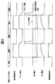
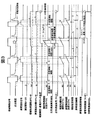
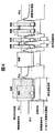
- FIG. 1 is a configuration diagram of a load drive system 1 according to a first embodiment. 7 shows a waveform of an output 72 of the driving device 20 when the switch element 70 is ON / OFF controlled. 5 is a time chart for explaining a temporal change of a signal value representing a determination result by a signal measurement / comparison determination circuit 90. 5 is a time chart illustrating a relationship between a ground fault and energization identification.
- FIG. 3 is a configuration diagram of a load drive system 1 according to a second embodiment. 7 shows a waveform of an output 72 of the driving device 20 when the switch element 70 is ON / OFF controlled. 5 is a time chart illustrating a relationship between a disconnection failure and energization identification. 9 is another example of a time chart illustrating a change over time of a signal value representing a determination result by the signal measurement / comparison determination circuit 90.
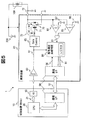
- FIG. 1 is a configuration diagram of a load drive system 1 according to Embodiment 1 of the present invention.
- the load drive system 1 is a system that drives and controls a fuel injection valve 100 that injects fuel into an internal combustion engine.
- the load drive system 1 includes a control device (Electronic Control Unit: ECU) 10 and a drive device (load drive circuit) 20.
- ECU Electronic Control Unit
- the drive device 20 is a device that controls the driving of the electric load by supplying a driving current to the electric load (here, the fuel injection valve 100).
- the output 72 of the driving device 20 is connected to the fuel injection valve 100, and the fuel injection valve 100 is controlled to open and close according to the current of the output 72.
- the control device 10 holds a fuel injection control program on a memory (not shown).
- the CPU (Central Processing Unit) 30 executes the program to calculate the combustion injection amount and its timing from the operation state and situation of the internal combustion engine.
- the CPU 30 generates an injection command 31 for each fuel injection valve 100 and outputs it to the drive device 20 from the IO port 40.
- the injection command 31 may be output to the drive device 20 through the communication interface 50 that exchanges setting and status information between the control device 10 and the drive device 20.
- the input signal determination circuit 60 receives the injection command 31 from the control device 10 and encodes it into an injection control signal 61 that becomes, for example, a High level during injection and a Low level during shutoff.
- the gate control circuit 65 sets the gate input 71 of the switch element 70 so that the switch element 70 (for example, MOSFET: Metal Oxide Semiconductor Field Effector Transistor) is turned on when the injection control signal 61 is High and turned off when it is Low. By controlling, the energization / interruption to the fuel injection valve 100 is controlled.
- the comparator 80 compares the voltage level of the output 72 with a predetermined energization determination threshold voltage 86. If the voltage level is lower than the energization determination threshold voltage 86, the switch element 70 is turned on (energized); otherwise, it is turned off (cut off). By making the determination, the operation state of the driving device 20 is identified. Examples of waveforms of the voltage level and the current level of the output 72 will be described later. Comparator 80 outputs the determination result as energization identification signal 81.
- the energization identification signal 81 is a signal indicating a High level when ON (energization) is determined, and a Low level when OFF (interruption) is determined. Although omitted in the figure, a filtering process for removing glitch noise or the like may be performed on the energization identification signal 81 to prevent erroneous determination.
- the energization determination threshold voltage 86 can be easily generated by the drive device 20 and does not make an erroneous determination between the voltage level lower limit value of the output 72 when the switch element 70 is OFF and the voltage level upper limit value when the switch element 70 is ON. It is preferable to set the voltage level with a margin as described above.
- the energization identification signal 81 is input to the signal measurement / comparison circuit 90 together with the injection control signal 61.
- the signal measurement / comparison / judgment circuit 90 judges whether or not the switch element 70 is operating normally (that is, whether or not abnormal energization has occurred) based on the input signal, and the result is determined via the communication interface 50. Is output to the control device 10.
- FIG. 2 shows a waveform of an output 72 of the drive device 20 when the switch element 70 is ON / OFF controlled.
- the output 72 to the fuel injection valve 100 is at a voltage level near the DC power supply 200 (battery or the like or its boosted voltage) connected to the upper electrode side of the fuel injection valve 100.
- the switch element 70 is controlled to be turned ON, the output 72 becomes a voltage level near GND, and the energization to the fuel injection valve 100 is started. Since the fuel injection valve 100 is an inductive load, the current flowing through the output 72 gradually increases, and the voltage level of the output 72 also increases due to the ON resistance of the switch element 70.
- the ON resistance of the switch element 70 is usually 0.5 ohm or less, even if a current of, for example, 1 A level required for opening the fuel injection valve 100 flows, the voltage level of the output 72 rises by several hundred mV or less. Fit within range.
- the switch element 70 When the switch element 70 is controlled to be turned off from the ON state, a large surge voltage is generated due to the back electromotive force caused by the inductive load of the fuel injection valve 100.
- the surge voltage is clamped by the active clamp circuit 75 between the gate input 71 and the output 72 of the switch element 70 to a voltage that does not exceed the device withstand voltage of the switch element 70, and the clamp voltage reduces the voltage of the gate input 71. To raise.
- the switch element 70 is turned on for a while, so that the output 72 drops from the level clamped by the active clamp circuit 75 to a level near the voltage of the DC power supply 200.
- FIG. 3 is a time chart for explaining the change over time of the signal value representing the judgment result by the signal measurement / comparison judgment circuit 90.
- the signal measurement / comparison / determination circuit 90 calculates (a) a response delay time between the injection control signal and the energization identification signal 81, (b) a difference (or ratio) between the injection control time and the energization time, and (c). The difference between the number of times of injection control and the number of times of energization is determined.
- the operation of the signal measurement / comparison / determination circuit 90 will be described with reference to FIG.
- the control device 10 transmits a measurement start trigger 56 to the drive device 20 through the communication interface 50 as a measurement start instruction. With this as a trigger, the control device 10 and the drive device 20 initialize the measurement function and start the measurement.
- the injection control signal 51 and the energization identification signal 81 received by the drive device 20 are not necessarily synchronized with the communication frame of the communication interface 50. Therefore, in synchronization with the first rise of the injection control signal 61 after the input of the measurement start trigger 56 (transition from the low level to the high level), the measurement function is initialized and the measurement is started.
- the input of the measurement start trigger 56 is not essential.
- the measurement is started from the time when the injection control signal 61 first rises, and the measurement result is transferred to the control device 10 by the communication interface 50. Then, the initialization and the measurement may be automatically started.
- the measurement start trigger 56 may be set individually for each measurement item.
- the cycle of the operation clock used in the drive device 20 can be used as a reference.
- a timer circuit having a minimum resolution obtained by multiplying the required time accuracy by a constant can be used.
- a value for example, an abnormality determination threshold value
- the response delay time is the time from the rising of the injection control signal 61 to the rising of the energization identification signal 81 which is a response to the injection control signal 61.
- the signal measurement / comparison determination circuit 90 compares the measured response delay time with an allowable delay threshold (time window).
- the permissible delay threshold can be set, for example, based on the worst-case value of the propagation delay in and out of the drive device 20 from the injection control signal 61 to the energization identification signal 81. If the response delay time is equal to or greater than the allowable delay threshold, it is determined that the response delay is abnormal. When a response delay abnormality is detected, the identification flag is stored in a register. The register holds the identification flag until the information is transferred to the control device 10 through the communication interface 50.
- the injection control time is the time from the rising to the falling of the injection control signal 61 (transition from a low level to a high level).
- the energization time is the time from the rise to the fall of the energization identification signal 81. Assuming that the injection control signal 51 and the energization identification signal 81 each transition from a low level to a high level and transition to a low level again as one pulse, the signal measurement / comparison / determination circuit 90 performs measurement for each one pulse. Will do.
- the measurement result of the injection control time of the injection control signal 51 indicates that The measurement is kept on the register until the measurement of the energization time of the identification signal 81 is completed.
- the signal measurement / comparison / judgment circuit 90 compares / determines the injection control time and the energization time when the measurement result of the energization time is obtained.
- the drive device 20 fails and does not appear even if it exceeds the response delay allowable delay threshold of the rise of the energization identification signal 81, it is considered that energization has not occurred, and the energization time “0” is set when the measurement of the injection control time is completed. And it is sufficient. If the fall of the energization identification signal 81 does not appear due to the output 72 of the drive device 20 sticking to the GND level or the like, the energization identification signal 81 ends the energization time measurement of the pulse when the maximum measurement time is reached, The energization time may be the maximum measurement time.
- the signal measurement / comparison determination circuit 90 calculates an absolute value error, a ratio accuracy error, and the like based on an allowable determination criterion for an error between the injection control time and the energization time.
- the signal measurement / comparison / judgment circuit 90 judges an abnormality in the energization time for each pulse of the injection control signal using the allowable error amount as a threshold. If an error exceeding the allowable error amount is detected, a flag indicating that fact is stored in a register. The register holds the flag until the information is transferred to the control device 10 through the communication interface 50.
- the injection control count is the number of times the injection control signal 61 rises.
- the number of times of energization is the number of times the energization identification signal 81 rises. Usually, the number of times of injection control and the number of times of energization match, but the rise of the energization identification signal 81 which is a response to the rise of the injection control signal 61 has a response delay. After waiting for the rise of the energization identification signal 81, the number of times of injection control and the number of energizations are compared. If an error exceeding the allowable error amount is detected, a flag indicating that fact is stored in a register. The register holds the flag until the information is transferred to the control device 10 through the communication interface 50.
- the comparison determination may be performed when the allowable delay threshold is reached.
- the comparison determination result is not limited to the presence or absence of an error between the number of times of injection control and the number of times of energization, and may indicate the comparison determination result by, for example, a difference value between the number of times of injection control and the number of times of energization.
- the maximum count value of the number of times of injection control may be determined from the frequency (period) of access to the measurement result via the communication interface 50, the number of injections assumed between accesses, and the like.
- the signal measurement / comparison / determination circuit 90 transfers the response delay time, the injection control time / energization time, the number of injection control times / energization times described with reference to FIG. Using the comparison determination result 91, the control device 10 can diagnose an abnormality of the drive device 20 which leads to a problem in the fuel injection amount or the injection timing.
- the control device 10 performs processing such as issuing an engine warning in accordance with the presence or absence and the content of the abnormality.
- FIG. 4 is a time chart for explaining a relationship between a ground fault and energization identification.
- the signal measurement / comparison determination circuit 90 can determine the power supply state of the switch element 70 and detect the occurrence of a ground fault by comparing the power supply identification signal 81 with the power supply determination threshold.
- the signal measurement / comparison determination circuit 90 determines the occurrence of a ground fault during a period during which the injection control signal 61 instructs the switch element 70 to be shut off. Accordingly, the signal measurement / comparison / determination circuit 90 can perform the determination of the energization state of the switch element 70 and the determination of the ground fault failure separately from each other.
- the signal measurement / comparison determination circuit 90 determines such energization as abnormal energization.
- the third and fourth energizations are regarded as abnormal energizations.
- the signal measurement / comparison / determination circuit 90 measures the third and fourth energization times as abnormal energization times. In the example of FIG. 4, even after the first energization is completed, the energization determination is continued due to a ground fault. Therefore, the signal measurement / comparison / determination circuit 90 regards the entire first energization period as abnormal energization.
- the drive device 20 determines the energization state of the switch element 70 using the output voltage of the switch element 70, and transmits the determination result to the control device 10.
- the drive device 20 determines the energization state of the switch element 70 using the output voltage of the switch element 70, and transmits the determination result to the control device 10.
- the drive device 20 since the drive device 20 determines the energization state of the switch element 70, it is not necessary to transmit the energization identification signal 81 to the control device 10 in real time, for example. Therefore, there is no need to provide a high-speed communication channel between the control device 10 and the drive device 20, and the existing communication interface 50 can be used. Therefore, the fuel injection timing and the fuel injection time can be appropriately monitored with a simple configuration.
- the energization identification signal 81 output by the comparator 80 can be shared for both ground fault detection and energization identification. Therefore, for example, when the drive device 20 has a circuit configuration for detecting a ground fault in advance, it is possible to identify the energized state of the switch element 70 using the circuit configuration. That is, there is an advantage that the object of the present invention can be achieved without largely changing the design of the driving device 20.
- FIG. 5 is a configuration diagram of the load drive system 1 according to the second embodiment of the present invention.
- the load drive system 1 according to the second embodiment includes a comparator 85 in addition to the configuration described in the first embodiment.
- the comparator 85 compares the voltage level of the output 72 with a second threshold voltage 88 described later.
- the energization identification signal 81 is calculated by performing an AND operation on the output of the comparator 80 and the negation of the output of the comparator 85. The criteria used by the signal measurement / comparison circuit 90 will be described later.
- FIG. 6 shows a waveform of the output 72 of the driving device 20 when the switch element 70 is ON / OFF controlled.
- the output 72 of the comparator 80 transitions to a voltage level near GND and then gradually rises due to the current flowing through the output 72.
- ON (energization) / OFF (interruption) of the switch element 70 is identified.
- the comparator 80 determines ON / OFF of the switch element 70 by comparing the voltage level of the output 72 with the first threshold voltage 87.
- the comparator 85 determines whether a current is flowing through the switch element 70 by comparing the voltage level of the output 72 with the second threshold voltage 88.
- the signal measurement / comparison / determination circuit 90 determines that the switch element 70 is ON (energized), and is OFF otherwise. (Interruption) is determined.
- the first threshold voltage 87 may be the same voltage level as the energization determination threshold voltage 86 in FIG.
- the second threshold voltage 88 has a small variation in the determination between the voltage level upper limit value when the switch element 70 is ON and the GND level, and a voltage level having a margin so as not to make an erroneous determination. Set.
- the output 72 passes through a value range from the first threshold voltage 87 to the second threshold voltage 88. That is, during the transition from the OFF (interruption) determination to the ON (energization) determination, a period in which the ON (energization) determination is performed once occurs (a portion surrounded by a dotted-line circle in FIG. 6).
- the instantaneous energization identification signal 81 may be removed by a glitch removing filter or the like, or the same processing may be performed by the signal measurement / comparison circuit 90 ignoring the instantaneous ON determination.
- the filter may be provided in the signal measurement / comparison / determination circuit 90, for example.
- FIG. 7 is a time chart for explaining the relationship between a disconnection failure and energization identification.
- the voltage level of the output 72 is reduced.
- the occurrence of disconnection can be detected.
- This disconnection detection threshold may be common to the energization determination threshold of the switch element 70. That is, when the voltage level of the output 72 is lower than the first threshold voltage 87 and higher than the second threshold voltage 88, the signal measurement / comparison / determination circuit 90 determines that a disconnection has occurred. However, the signal measurement / comparison determination circuit 90 determines the occurrence of disconnection during a period during which the injection control signal 61 instructs the switch element 70 to be energized. Therefore, the signal measurement / comparison / determination circuit 90 can perform the conduction state determination and the disconnection determination of the switch element 70 separately from each other.
- the energization identification signal 81 transitions to the OFF state earlier than the injection control period in the energized period.
- the signal measurement / comparison determination circuit 90 determines such energization as abnormal energization.
- the second to fourth energizations are regarded as abnormal energizations.
- the signal measurement / comparison determination circuit 90 measures the second to fourth energization times as abnormal energization times. In the example of FIG. 7, since the disconnection has occurred over the entire first injection control period, the energization time is zero. Therefore, the signal measurement / comparison / determination circuit 90 regards the entire first injection control period as abnormal energization.
- the conduction identification signal 81 constituted by the output of the comparator 80 and the output of the comparator 85 can be shared for both disconnection detection and conduction identification. Therefore, for example, when the drive device 20 has a circuit configuration for detecting disconnection in advance, it is possible to identify the energized state of the switch element 70 using the circuit configuration. That is, there is an advantage that the object of the present invention can be achieved without largely changing the design of the driving device 20.
- FIG. 8 is another example of a time chart for explaining a temporal change of a signal value representing a determination result by the signal measurement / comparison determination circuit 90.
- the signal measurement / comparison / determination circuit 90 performs the comparison / determination on the measurement result, but the controller 10 may perform the comparison / determination.
- the measuring method of each input signal to be measured is the same as that of FIG. Therefore, an arithmetic circuit for performing the comparison and determination and a register for storing the determination result are not required, but a register for storing the measurement result such as the response delay time / the injection control time / the energization time is additionally required.
- the measurement result is stored in the numbered register every time the time from the rising of the injection control signal 61 to the rising of the energization identification signal 81 is measured.
- the rise of the energization identification signal 81 with respect to the injection control signal 61 exceeds the allowable delay threshold value of the response delay time due to an abnormality of the drive device 20 or the like, the measurement at the time when the excess or the maximum response delay measurement time (timeout) is reached is reached. Store the time in a register.
- the injection control time for each pulse of the injection control signal 61 and the energization time for each pulse of the energization identification signal 81 are also stored in a numbered register each time measurement is performed. If the rise of the energization identification signal 81 exceeds the allowable delay threshold value of the response delay time due to an abnormality of the drive device 20 and does not appear even after the end of the injection control time corresponding to one pulse of the injection control signal 61, it is determined that there is no energization. Assuming that the energization time “0” is stored in the register when the measurement of the injection control time is completed.
- the energization time measurement of the pulse is terminated when the maximum measurement time is reached, and the energization time is set to the maximum. What is necessary is just to store it in a register as a measurement time.
- the control device 10 compares the injection control time and the energization time between register data of the same number. Therefore, it is necessary to store the measurement result of the injection control signal 61 and the corresponding energization identification signal 81 in the register of the same number. Specifically, when the energization identification signal 81 rises within the allowable delay threshold after the injection control signal 61 rises, the two may be paired and stored in the register of the same number. Furthermore, according to the transfer timing of the communication interface 50, only data whose comparison target data has been updated is transferred so that a mismatch between the number of times of injection control and the number of times of energization or a mismatch between the injection control time and time of energization does not occur. Alternatively, it is desirable to add a flag for displaying the flag so that erroneous determination does not occur.
- the present invention is not limited to the above embodiment, and includes various modifications.
- the above embodiment has been described in detail in order to explain the present invention in an easy-to-understand manner, and is not necessarily limited to one having all the described configurations.
- a part of the configuration of one embodiment can be replaced with the configuration of another embodiment, and the configuration of one embodiment can be added to the configuration of another embodiment.
- the control device 10 and the drive device 20 may share and execute comparison and determination for each measurement item.
- the drive device 20 performs a comparison determination on the response delay time, performs only the measurement on the injection control time, the energization time, the number of injection controls, and the number of energizations and transmits the result to the control device 10. .
- control lines and information lines indicate those which are considered necessary for explanation, and do not necessarily indicate all control lines and information lines on a product. In fact, it may be considered that almost all components are interconnected.
- Control device 20 Drive device 30: CPU31: Injection command 40: IO port 50: Communication interface 56: Measurement start trigger 60: Input signal determination circuit 61: Injection control signal 65: Gate control circuit 70: Switch element 71: Gate Input 72: output 80, 85: comparator 81: energization identification signal 86: energization determination threshold voltage 87: first threshold voltage 88: second threshold voltage 90: signal measurement / comparison determination circuit 91: comparison determination result 100: fuel injection valve 200: DC power supply
Landscapes
- Engineering & Computer Science (AREA)
- Chemical & Material Sciences (AREA)
- Combustion & Propulsion (AREA)
- Mechanical Engineering (AREA)
- General Engineering & Computer Science (AREA)
- Computer Hardware Design (AREA)
- Microelectronics & Electronic Packaging (AREA)
- Electrical Control Of Air Or Fuel Supplied To Internal-Combustion Engine (AREA)
- Fuel-Injection Apparatus (AREA)
- Combined Controls Of Internal Combustion Engines (AREA)
Abstract
Description
図1は、本発明の実施形態1に係る負荷駆動システム1の構成図である。負荷駆動システム1は、内燃機関に対して燃料を噴射する燃料噴射弁100を駆動制御するシステムである。負荷駆動システム1は、制御装置(Electronic Control Unit:ECU)10と駆動装置(負荷駆動回路)20を備える。
本実施形態1に係る負荷駆動システム1において、駆動装置20はスイッチ素子70の出力電圧を用いてスイッチ素子70の通電状態を判定し、その判定結果を制御装置10に対して送信する。スイッチ素子70の出力電圧を用いて判定することにより、出力電流を検出するための検出抵抗などを燃料噴射弁100ごとに設ける必要がなくなるので、駆動装置20と制御装置10ともに新たな入力端子を設ける必要はない。したがって簡易な構成により、燃料噴射タイミングや燃料噴射時間を適切に監視することができる。
図5は、本発明の実施形態2に係る負荷駆動システム1の構成図である。本実施形態2に係る負荷駆動システム1は、実施形態1で説明した構成に加えて、コンパレータ85を備える。コンパレータ85は、出力72の電圧レベルと、後述する第2閾値電圧88とを比較する。通電識別信号81は、コンパレータ80の出力と、コンパレータ85の出力の否定とを論理積演算することにより算出される。信号測定・比較判定回路90による判定基準については後述する。
本実施形態2に係る負荷駆動システム1において、信号測定・比較判定回路90は、出力72の電圧レベルが第1閾値電圧87より低く第2閾値電圧88より高い場合は、スイッチ素子70が通電状態であると判定する。第2閾値電圧88を併用することにより、スイッチ素子70が通電状態であることに加えて、実際に燃料噴射弁100に電流が流れているか否かを推定することができる。これにより、負荷駆動システム1としての異常検出精度を向上させることができる。
図8は、信号測定・比較判定回路90による判定結果を表す信号値の経時変化を説明するタイムチャートの別例である。図3で説明したタイムチャートにおいて、信号測定・比較判定回路90は測定結果に対する比較判定を実施しているが、比較判定を制御装置10が実施してもよい。この場合、各被測定入力信号の測定方法は図3と同様であるが、各被測定入力信号の1パルス毎の測定結果をレジスタにストアしておく必要がある。よって比較判定を実施するための演算回路や判定結果を格納するレジスタは不要となる代わりに、応答遅延時間/噴射制御時間/通電時間などの測定結果を格納するレジスタが追加で必要となる。
本発明は上記実施形態に限定されるものではなく、様々な変形例が含まれる。例えば、上記実施形態は本発明を分かりやすく説明するために詳細に説明したものであり、必ずしも説明した全ての構成を備えるものに限定されるものではない。また、ある実施形態の構成の一部を他の実施形態の構成に置き換えることが可能であり、また、ある実施形態の構成に他の実施形態の構成を加えることも可能である。また、各実施形態の構成の一部について、他の構成の追加・削除・置換をすることが可能である。
Claims (15)
- 負荷(燃料噴射弁)を駆動するスイッチ素子を備える負荷駆動回路において、
前記スイッチ素子の駆動指令と、前記スイッチ素子の出力端の信号に基づいて前記スイッチ素子の応答性の異常を診断する診断部を備える
ことを特徴とする負荷駆動回路。 - 前記負荷駆動回路はさらに、
前記駆動指令を送信する制御装置から前記駆動指令を受け取る端子、
前記制御装置との間でデータを送受信する通信インターフェース、
を備え、
前記診断部は、前記通信インターフェースを介して前記診断の結果を前記制御装置に対して送信する
ことを特徴とする請求項1記載の負荷駆動回路。 - 前記負荷駆動回路はさらに、前記スイッチ素子の出力端の電圧と所定電圧閾値とを比較することにより、前記スイッチ素子が通電状態であるか遮断状態であるかを判別するとともに、その判別結果を表す通電識別信号を出力する、通電識別信号生成部を備え、
前記診断部は、前記通電識別信号を用いて、前記駆動指令と前記通電識別信号との間の遅延時間、前記スイッチ素子の通電時間、または前記スイッチ素子の通電回数のうち少なくともいずれかを診断する
ことを特徴とする請求項1記載の負荷駆動回路。 - 前記負荷駆動回路はさらに、
前記駆動指令を送信する制御装置から前記駆動指令を受け取る端子、
前記制御装置との間でデータを送受信する通信インターフェース、
を備え、
前記診断部は、前記通電識別信号を用いた前記診断の結果を、前記通信インターフェースを介して前記制御装置に対して送信する
ことを特徴とする請求項3記載の負荷駆動回路。 - 前記負荷駆動回路はさらに、前記スイッチ素子の出力端の電圧と所定電圧閾値とを比較することにより、前記スイッチ素子が通電状態であるか遮断状態であるかを判別するとともに、その判別結果を表す通電識別信号を出力する、通電識別信号生成部を備え、
前記診断部は、前記通電識別信号を用いて前記スイッチ素子を診断するとともに、前記通電識別信号を用いて、前記負荷の地絡故障が生じたか否かを判定する
ことを特徴とする請求項1記載の負荷駆動回路。 - 前記診断部は、前記駆動指令が前記スイッチ素子を遮断状態にするよう指示している遮断期間において、前記通電識別信号を用いて、前記負荷の地絡故障が生じたか否かを判定し、
前記診断部は、前記遮断期間において前記負荷の地絡故障が生じたと判定した場合は、前記スイッチ素子が異常通電したと判定する
ことを特徴とする請求項5記載の負荷駆動回路。 - 前記負荷駆動回路はさらに、前記スイッチ素子の出力端の電圧と所定電圧閾値とを比較することにより、前記スイッチ素子が通電状態であるか遮断状態であるかを判別するとともに、その判別結果を表す通電識別信号を出力する、通電識別信号生成部を備え、
前記診断部は、前記通電識別信号を用いて前記スイッチ素子を診断するとともに、前記通電識別信号を用いて、前記負荷駆動回路と前記負荷を接続する配線が断線したか否かを判定する
ことを特徴とする請求項1記載の負荷駆動回路。 - 前記診断部は、前記駆動指令が前記スイッチ素子を通電状態にするよう指示している通電期間において、前記通電識別信号を用いて、前記配線が断線したか否かを判定し、
前記診断部は、前記通電期間において前記配線が断線したと判定した場合は、前記通電期間のうち前記配線が断線していない期間において前記スイッチ素子が異常通電したと判定する
ことを特徴とする請求項7記載の負荷駆動回路。 - 前記診断部は、前記駆動指令が前記スイッチ素子を通電状態にするよう指示してから、前記スイッチ素子が通電状態になるまでの遅延時間が、所定のタイムウインドウのなかに収まっているか否かを判定し、
前記診断部は、前記遅延時間が前記タイムウインドウのなかに収まっていない場合はその旨を表す異常フラグを出力する
ことを特徴とする請求項1記載の負荷駆動回路。 - 前記診断部は、前記スイッチ素子が通電状態になった期間を判定し、
前記診断部は、前記駆動指令が前記スイッチ素子を通電状態にするよう指示した時間と前記スイッチ素子が通電状態になった時間との間の差分、または比率を計算し、
前記診断部は、前記差分または前記比率が所定の判定閾値以内に収まっていない場合はその旨を表す異常フラグを出力する
ことを特徴とする請求項1記載の負荷駆動回路。 - 前記診断部は、前記スイッチ素子が通電状態になった回数を判定し、
前記診断部は、前記駆動指令が前記スイッチ素子を通電状態にするよう指示した回数と前記スイッチ素子が通電状態になった回数との間の差分を計算し、
前記診断部は、前記差分が所定の判定閾値以内に収まっていない場合はその旨を表す異常フラグを出力する
ことを特徴とする請求項1記載の負荷駆動回路。 - 前記負荷は、内燃機関に対して燃料を噴射する燃料噴射弁を開閉する電気負荷として構成されており、
前記駆動指令は、燃料を噴射するよう前記負荷に対して指示する指令であり、
前記駆動指令は、前記内燃機関の1回の燃焼サイクルにおいて燃料の噴射タイミングと噴射時間を1回以上指示する指令であり、
前記負荷駆動回路は、前記駆動指令にしたがって、前記燃料噴射弁を開閉するように前記負荷を通電する
ことを特徴とする請求項1記載の負荷駆動回路。 - 前記負荷駆動回路は、前記診断部による前記診断の結果を記憶する記憶装置を備え、
前記診断部は、前記駆動指令が前記噴射タイミングと前記噴射時間を指示するごとに、前記診断の結果を前記記憶装置に対して格納する
ことを特徴とする請求項12記載の負荷駆動回路。 - 請求項1記載の負荷駆動回路、
前記負荷駆動回路に対して前記駆動指令を送信する制御装置、
を有することを特徴とする負荷駆動システム。 - 前記制御装置は、
前記負荷駆動回路に対して前記駆動指令を送信する端子、
前記診断部による前記診断の結果を前記負荷駆動回路から受け取る通信インターフェース、
を備える
ことを特徴とする請求項14記載の負荷駆動システム。
Priority Applications (4)
| Application Number | Priority Date | Filing Date | Title |
|---|---|---|---|
| DE112019002170.2T DE112019002170B4 (de) | 2018-07-03 | 2019-06-11 | Lastansteuerschaltung und lastansteuersystem |
| CN201980034013.1A CN112352095B (zh) | 2018-07-03 | 2019-06-11 | 负载驱动电路、负载驱动系统 |
| US17/052,888 US11542885B2 (en) | 2018-07-03 | 2019-06-11 | Load drive circuit and load drive system |
| JP2020528753A JP7304856B2 (ja) | 2018-07-03 | 2019-06-11 | 負荷駆動回路、負荷駆動システム |
Applications Claiming Priority (2)
| Application Number | Priority Date | Filing Date | Title |
|---|---|---|---|
| JP2018126706 | 2018-07-03 | ||
| JP2018-126706 | 2018-07-03 |
Publications (1)
| Publication Number | Publication Date |
|---|---|
| WO2020008816A1 true WO2020008816A1 (ja) | 2020-01-09 |
Family
ID=69060233
Family Applications (1)
| Application Number | Title | Priority Date | Filing Date |
|---|---|---|---|
| PCT/JP2019/023016 Ceased WO2020008816A1 (ja) | 2018-07-03 | 2019-06-11 | 負荷駆動回路、負荷駆動システム |
Country Status (5)
| Country | Link |
|---|---|
| US (1) | US11542885B2 (ja) |
| JP (1) | JP7304856B2 (ja) |
| CN (1) | CN112352095B (ja) |
| DE (1) | DE112019002170B4 (ja) |
| WO (1) | WO2020008816A1 (ja) |
Citations (3)
| Publication number | Priority date | Publication date | Assignee | Title |
|---|---|---|---|---|
| JP2006220039A (ja) * | 2005-02-09 | 2006-08-24 | Denso Corp | 誘導負荷駆動回路 |
| JP2013036344A (ja) * | 2011-08-03 | 2013-02-21 | Denso Corp | 燃料噴射制御装置及び燃料噴射制御システム |
| JP2013204442A (ja) * | 2012-03-27 | 2013-10-07 | Denso Corp | インジェクタ駆動装置 |
Family Cites Families (23)
| Publication number | Priority date | Publication date | Assignee | Title |
|---|---|---|---|---|
| JPS588262A (ja) * | 1981-07-08 | 1983-01-18 | Nissan Motor Co Ltd | 自動車の故障診断装置 |
| JPS6098146A (ja) * | 1983-11-02 | 1985-06-01 | Nippon Soken Inc | 内燃機関の燃料制御方法 |
| JPH0758054B2 (ja) * | 1989-06-19 | 1995-06-21 | 株式会社ユニシアジェックス | 内燃機関の燃料供給制御装置における学習補正装置及び自己診断装置 |
| DE19515508C2 (de) * | 1994-04-28 | 1999-01-28 | Hitachi Ltd | Verfahren und Steuervorrichtung zur Antriebssteuerung eines Fahrzeugs mit Verbrennungsmotor und Getriebe |
| JP2000345901A (ja) * | 1999-05-31 | 2000-12-12 | Isuzu Motors Ltd | 電子燃料噴射装置 |
| US7475234B2 (en) * | 2004-02-10 | 2009-01-06 | Denso Corporation | Electronic control apparatus equipped with malfunction monitor |
| JP4174500B2 (ja) * | 2005-07-29 | 2008-10-29 | 三菱電機株式会社 | 車両用内燃機関の制御装置 |
| JP2008190388A (ja) * | 2007-02-02 | 2008-08-21 | Denso Corp | 電磁弁駆動装置及び燃料噴射制御装置 |
| JP4648952B2 (ja) | 2008-01-22 | 2011-03-09 | 日立オートモティブシステムズ株式会社 | 内燃機関制御装置 |
| JP4883106B2 (ja) * | 2009-02-12 | 2012-02-22 | 株式会社デンソー | インジェクタ駆動装置 |
| JP5542884B2 (ja) * | 2012-08-30 | 2014-07-09 | 三菱電機株式会社 | 車載エンジン制御装置 |
| US10502155B2 (en) * | 2013-07-10 | 2019-12-10 | Hitachi Automotive Systems, Ltd. | Control device for internal combustion engine |
| EP3597899B1 (en) * | 2013-07-29 | 2026-01-21 | Astemo, Ltd. | Drive device for fuel injection device, and fuel injection system |
| JP6130280B2 (ja) * | 2013-09-25 | 2017-05-17 | 日立オートモティブシステムズ株式会社 | 燃料噴射装置の駆動装置 |
| WO2015156371A1 (ja) * | 2014-04-10 | 2015-10-15 | 株式会社デンソー | 制御装置及び点火装置 |
| JP6381970B2 (ja) * | 2014-05-30 | 2018-08-29 | 日立オートモティブシステムズ株式会社 | 燃料噴射装置の駆動装置 |
| JP6183341B2 (ja) * | 2014-12-03 | 2017-08-23 | 株式会社デンソー | インジェクタ駆動装置 |
| US10309336B2 (en) * | 2015-02-09 | 2019-06-04 | Hitachi Automotive Systems, Ltd. | Control device for fuel injection valve |
| JP6260552B2 (ja) * | 2015-02-26 | 2018-01-17 | 株式会社オートネットワーク技術研究所 | 電力供給装置 |
| JP6597535B2 (ja) * | 2016-09-13 | 2019-10-30 | 株式会社デンソー | 弁体作動推定装置 |
| WO2018155084A1 (ja) * | 2017-02-21 | 2018-08-30 | 日立オートモティブシステムズ株式会社 | 電子制御装置および電子制御装置の異常正常判定方法 |
| JP7110613B2 (ja) * | 2018-02-21 | 2022-08-02 | 株式会社デンソー | 負荷駆動装置 |
| JP6970823B2 (ja) * | 2018-05-23 | 2021-11-24 | 日立Astemo株式会社 | 燃料噴射制御装置 |
-
2019
- 2019-06-11 CN CN201980034013.1A patent/CN112352095B/zh active Active
- 2019-06-11 US US17/052,888 patent/US11542885B2/en active Active
- 2019-06-11 JP JP2020528753A patent/JP7304856B2/ja active Active
- 2019-06-11 DE DE112019002170.2T patent/DE112019002170B4/de active Active
- 2019-06-11 WO PCT/JP2019/023016 patent/WO2020008816A1/ja not_active Ceased
Patent Citations (3)
| Publication number | Priority date | Publication date | Assignee | Title |
|---|---|---|---|---|
| JP2006220039A (ja) * | 2005-02-09 | 2006-08-24 | Denso Corp | 誘導負荷駆動回路 |
| JP2013036344A (ja) * | 2011-08-03 | 2013-02-21 | Denso Corp | 燃料噴射制御装置及び燃料噴射制御システム |
| JP2013204442A (ja) * | 2012-03-27 | 2013-10-07 | Denso Corp | インジェクタ駆動装置 |
Also Published As
| Publication number | Publication date |
|---|---|
| JPWO2020008816A1 (ja) | 2021-06-24 |
| US11542885B2 (en) | 2023-01-03 |
| CN112352095B (zh) | 2022-11-08 |
| JP7304856B2 (ja) | 2023-07-07 |
| US20210131373A1 (en) | 2021-05-06 |
| DE112019002170B4 (de) | 2026-03-05 |
| CN112352095A (zh) | 2021-02-09 |
| DE112019002170T5 (de) | 2021-01-28 |
Similar Documents
| Publication | Publication Date | Title |
|---|---|---|
| US11387777B2 (en) | Active bypass control device and method for photovoltaic module | |
| CN102182603B (zh) | 一种高压共轨燃油喷射系统故障诊断装置及其方法 | |
| CN104040819B (zh) | 用于高功率负载的可诊断反向电压保护 | |
| CN105991010A (zh) | 验证栅极驱动器保护逻辑 | |
| JP2010513796A (ja) | 電磁バルブの制御装置 | |
| CN104727962B (zh) | 喷射器驱动器及其控制方法 | |
| US12181380B2 (en) | Detection apparatus and server | |
| CN110609538B (zh) | 故障处理方法、装置、设备及存储介质 | |
| KR20040081176A (ko) | 부하의 고장 진단 방법 및 장치, 및 부하의 고장 처리방법 및 장치 | |
| JP7304856B2 (ja) | 負荷駆動回路、負荷駆動システム | |
| JP6625668B2 (ja) | 電磁負荷駆動装置、車載制御システム | |
| US20090255281A1 (en) | Diagnostic Method for Proper Refrigerant Valve Operation | |
| CN202132161U (zh) | 一种高压共轨燃油喷射系统故障诊断装置 | |
| CN114184953A (zh) | 继电器驱动电路的异常诊断方法及系统 | |
| KR102053991B1 (ko) | 자가 진단이 가능한 워치독 모니터링 시스템 | |
| CN113711063A (zh) | 功率器件监测系统和监测方法 | |
| CN110444444A (zh) | 驱动接触器的电路 | |
| CN110307108B (zh) | 喷油器的辅助控制方法、辅助控制装置及辅助控制系统 | |
| CN108631567A (zh) | 一种实现电路保护的方法及保护电路 | |
| CN115436843A (zh) | 一种针脚传感器线束连接顺序检测方法及系统 | |
| CN113917320A (zh) | 一种换流阀故障预警方法及系统 | |
| US10606329B2 (en) | Safety circuit for an electrical system | |
| JP2015021954A (ja) | 電流制御装置 | |
| JPS63248969A (ja) | 燃料噴射装置の故障診断装置 | |
| JP2006209618A (ja) | デジタル出力装置およびデジタル出力装置を用いた診断方法 |
Legal Events
| Date | Code | Title | Description |
|---|---|---|---|
| 121 | Ep: the epo has been informed by wipo that ep was designated in this application |
Ref document number: 19829850 Country of ref document: EP Kind code of ref document: A1 |
|
| WWE | Wipo information: entry into national phase |
Ref document number: 112019002170 Country of ref document: DE |
|
| WWE | Wipo information: entry into national phase |
Ref document number: 2020528753 Country of ref document: JP |
|
| 122 | Ep: pct application non-entry in european phase |
Ref document number: 19829850 Country of ref document: EP Kind code of ref document: A1 |
|
| WWG | Wipo information: grant in national office |
Ref document number: 112019002170 Country of ref document: DE |