JP6260552B2 - 電力供給装置 - Google Patents
電力供給装置 Download PDFInfo
- Publication number
- JP6260552B2 JP6260552B2 JP2015036856A JP2015036856A JP6260552B2 JP 6260552 B2 JP6260552 B2 JP 6260552B2 JP 2015036856 A JP2015036856 A JP 2015036856A JP 2015036856 A JP2015036856 A JP 2015036856A JP 6260552 B2 JP6260552 B2 JP 6260552B2
- Authority
- JP
- Japan
- Prior art keywords
- power supply
- switch
- supply path
- voltage
- state
- Prior art date
- Legal status (The legal status is an assumption and is not a legal conclusion. Google has not performed a legal analysis and makes no representation as to the accuracy of the status listed.)
- Expired - Fee Related
Links
Images


Classifications
-
- H—ELECTRICITY
- H03—ELECTRONIC CIRCUITRY
- H03K—PULSE TECHNIQUE
- H03K17/00—Electronic switching or gating, i.e. not by contact-making and –breaking
- H03K17/08—Modifications for protecting switching circuit against overcurrent or overvoltage
- H03K17/081—Modifications for protecting switching circuit against overcurrent or overvoltage without feedback from the output circuit to the control circuit
- H03K17/0812—Modifications for protecting switching circuit against overcurrent or overvoltage without feedback from the output circuit to the control circuit by measures taken in the control circuit
- H03K17/08122—Modifications for protecting switching circuit against overcurrent or overvoltage without feedback from the output circuit to the control circuit by measures taken in the control circuit in field-effect transistor switches
-
- G—PHYSICS
- G01—MEASURING; TESTING
- G01R—MEASURING ELECTRIC VARIABLES; MEASURING MAGNETIC VARIABLES
- G01R31/00—Arrangements for testing electric properties; Arrangements for locating electric faults; Arrangements for electrical testing characterised by what is being tested not provided for elsewhere
- G01R31/327—Testing of circuit interrupters, switches or circuit-breakers
- G01R31/3277—Testing of circuit interrupters, switches or circuit-breakers of low voltage devices, e.g. domestic or industrial devices, such as motor protections, relays, rotation switches
-
- H—ELECTRICITY
- H02—GENERATION; CONVERSION OR DISTRIBUTION OF ELECTRIC POWER
- H02H—EMERGENCY PROTECTIVE CIRCUIT ARRANGEMENTS
- H02H3/00—Emergency protective circuit arrangements for automatic disconnection directly responsive to an undesired change from normal electric working condition with or without subsequent reconnection ; integrated protection
- H02H3/02—Details
- H02H3/04—Details with warning or supervision in addition to disconnection, e.g. for indicating that protective apparatus has functioned
- H02H3/044—Checking correct functioning of protective arrangements, e.g. by simulating a fault
-
- H—ELECTRICITY
- H02—GENERATION; CONVERSION OR DISTRIBUTION OF ELECTRIC POWER
- H02H—EMERGENCY PROTECTIVE CIRCUIT ARRANGEMENTS
- H02H3/00—Emergency protective circuit arrangements for automatic disconnection directly responsive to an undesired change from normal electric working condition with or without subsequent reconnection ; integrated protection
- H02H3/02—Details
- H02H3/05—Details with means for increasing reliability, e.g. redundancy arrangements
-
- H—ELECTRICITY
- H02—GENERATION; CONVERSION OR DISTRIBUTION OF ELECTRIC POWER
- H02H—EMERGENCY PROTECTIVE CIRCUIT ARRANGEMENTS
- H02H3/00—Emergency protective circuit arrangements for automatic disconnection directly responsive to an undesired change from normal electric working condition with or without subsequent reconnection ; integrated protection
- H02H3/08—Emergency protective circuit arrangements for automatic disconnection directly responsive to an undesired change from normal electric working condition with or without subsequent reconnection ; integrated protection responsive to excess current
-
- H—ELECTRICITY
- H03—ELECTRONIC CIRCUITRY
- H03K—PULSE TECHNIQUE
- H03K17/00—Electronic switching or gating, i.e. not by contact-making and –breaking
- H03K17/08—Modifications for protecting switching circuit against overcurrent or overvoltage
- H03K17/082—Modifications for protecting switching circuit against overcurrent or overvoltage by feedback from the output to the control circuit
- H03K17/0822—Modifications for protecting switching circuit against overcurrent or overvoltage by feedback from the output to the control circuit in field-effect transistor switches
-
- H—ELECTRICITY
- H03—ELECTRONIC CIRCUITRY
- H03K—PULSE TECHNIQUE
- H03K5/00—Manipulating of pulses not covered by one of the other main groups of this subclass
- H03K5/22—Circuits having more than one input and one output for comparing pulses or pulse trains with each other according to input signal characteristics, e.g. slope, integral
- H03K5/24—Circuits having more than one input and one output for comparing pulses or pulse trains with each other according to input signal characteristics, e.g. slope, integral the characteristic being amplitude
-
- G—PHYSICS
- G01—MEASURING; TESTING
- G01R—MEASURING ELECTRIC VARIABLES; MEASURING MAGNETIC VARIABLES
- G01R31/00—Arrangements for testing electric properties; Arrangements for locating electric faults; Arrangements for electrical testing characterised by what is being tested not provided for elsewhere
- G01R31/005—Testing of electric installations on transport means
- G01R31/006—Testing of electric installations on transport means on road vehicles, e.g. automobiles or trucks
-
- G—PHYSICS
- G01—MEASURING; TESTING
- G01R—MEASURING ELECTRIC VARIABLES; MEASURING MAGNETIC VARIABLES
- G01R31/00—Arrangements for testing electric properties; Arrangements for locating electric faults; Arrangements for electrical testing characterised by what is being tested not provided for elsewhere
- G01R31/40—Testing power supplies
-
- H—ELECTRICITY
- H02—GENERATION; CONVERSION OR DISTRIBUTION OF ELECTRIC POWER
- H02H—EMERGENCY PROTECTIVE CIRCUIT ARRANGEMENTS
- H02H1/00—Details of emergency protective circuit arrangements
- H02H1/0007—Details of emergency protective circuit arrangements concerning the detecting means
-
- H—ELECTRICITY
- H02—GENERATION; CONVERSION OR DISTRIBUTION OF ELECTRIC POWER
- H02H—EMERGENCY PROTECTIVE CIRCUIT ARRANGEMENTS
- H02H3/00—Emergency protective circuit arrangements for automatic disconnection directly responsive to an undesired change from normal electric working condition with or without subsequent reconnection ; integrated protection
- H02H3/08—Emergency protective circuit arrangements for automatic disconnection directly responsive to an undesired change from normal electric working condition with or without subsequent reconnection ; integrated protection responsive to excess current
- H02H3/087—Emergency protective circuit arrangements for automatic disconnection directly responsive to an undesired change from normal electric working condition with or without subsequent reconnection ; integrated protection responsive to excess current for DC applications
-
- H—ELECTRICITY
- H03—ELECTRONIC CIRCUITRY
- H03K—PULSE TECHNIQUE
- H03K2217/00—Indexing scheme related to electronic switching or gating, i.e. not by contact-making or -breaking covered by H03K17/00
- H03K2217/0027—Measuring means of, e.g. currents through or voltages across the switch
Landscapes
- Physics & Mathematics (AREA)
- Nonlinear Science (AREA)
- General Physics & Mathematics (AREA)
- Emergency Protection Circuit Devices (AREA)
- Electronic Switches (AREA)
Description
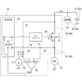
以下、図面を用いて本発明の実施形態について説明する。図1は本発明における電力供給装置10の全体構成を示すブロック図である。本発明の電力供給装置10は図示しない車両に搭載され、主電源50と負荷70をつなぐ給電路60をスイッチ20で導通および遮断することにより、負荷70への電力の供給を制御する。ここで、負荷70とは、車両が備える種々の電装品を意味している。主電源50はかかる負荷70を駆動する電力源であり、駆動用バッテリー51や、オルタネーターまたはハイブリッドモーターなどの発電機52を総括した構成を意味している。
以下に、図2を参照して本実施形態における過電流遮断機構についてより詳細に説明する。コンパレータ30のマイナス入力端子は、給電路60のスイッチ20よりも主電源50側の給電路である主電源側給電路62から分岐した配線31に接続されている。配線31には、抵抗器34および定電流源35が接続されており、抵抗器34の抵抗Rrefと定電流源35の電流Irefは一定である。これにより、抵抗器34における電圧Vref(主電源50の電圧Vbatからの電圧降下量)も一定となり、マイナス入力端子に印加される閾値電圧Vin(−)が一定に保たれる。上記関係は以下の式(1)により表すことができる。
Vin(−)=Vbat−(Rref×Iref)・・・(1)
Vds=Ron×I・・・(2)
Vin(+)=Vbat−Vds・・・(3)
以下に、本実施形態における電力供給装置10の故障診断方法について説明する。故障診断は制御回路40のタイマ割り込みにより周期的に、またはスイッチ20のオンオフ操作に連動して実行される。
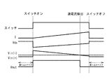
スイッチ制御手段41がスイッチ20をオフ操作した後、オン操作をする前における故障診断は、制御回路40が備える遮断時診断手段44により行われる。スイッチ制御手段41によりスイッチ20がオフ操作され、給電路60が遮断されたときは、主電源50からコンパレータ30のプラス入力端子に印加される入力電圧Vin(+)は0[V]になる。よって、コンパレータ30の動作が正常であるときは、その出力値Voutは、入力電圧Vin(+)が閾値電圧Vin(−)よりも低いことを示すLowとなるはずである。このときに出力値Voutがその逆の出力であるHiを示す場合、スイッチ20またはコンパレータ30に異常が生じているものと推測される。尚、スイッチ20のオフ操作直後はまだ負荷側給電路61から残留電圧が検出される可能性があるため、診断はスイッチ20のオフ操作から一定時間経過後に行う方が望ましい。
スイッチ制御手段41がスイッチ20をオン操作した後、オフ操作をする前における故障診断は、制御回路40が備える導通時診断手段45により行われる。スイッチ20がオン操作され、給電路60が導通されることにより、スイッチ20の抵抗Ronは電流Iの大きさに応じて電圧(電圧降下)Vrefを生じさせ、負荷側給電路61に接続されたコンパレータ30のプラス入力端子には、抵抗Ronによる電圧降下後の入力電圧Vin(+)が印加される。

以下、本発明の電力供給装置10の他の実施形態である電力供給装置11について説明する。図4は電力供給装置11の全体構成を示すブロック図である。電力供給装置11も電力供給装置10と同様に、図示しない車両に搭載され、主電源50から負荷70への電力の供給を制御する。その他、先の実施形態と同じ構成については同じ符号を付し、その詳細な説明を省略する。
電力供給装置11の給電路60には、主電源50のほか、負荷側給電路61に副電源55が接続されている。そのため、負荷側給電路61には主電源50の電圧Vbatまたは副電源55の電圧Vsbatのいずれか大きい方の電圧がかかることとなる。しかし、過電流が発生した際には、負荷70の抵抗は著しく低下していることが想定されるため、副電源55の電圧Vsbatは負荷70の方に優先的に印加され、配線32の方向へは及ばない。よって、電力供給装置11についても、電力供給装置10と同様の方法により過電流を検出することが可能である。
上で述べたように、電力供給装置11は副電源55を備えていることから、導通判定手段42はスイッチ20のオンオフ状態を、HiおよびLowの二値のみで判定することが困難である。
導通判定方法が異なることを除いては、電力供給装置11も、電力供給装置10と同じように故障診断を行うことができる。さらに、電力供給装置11は副電源55を備えていることから、負荷70が駆動中であっても、一時的にスイッチ20をオフにして、給電路60遮断時の故障診断を行うことが可能である。
20 スイッチ
30 コンパレータ
36 下流検知手段
37 上流検知手段
40 制御回路
41 スイッチ制御手段
42 導通判定手段
43 過電流検知手段
44 遮断時診断手段
45 導通時診断手段
50 主電源
55 副電源
60 給電路
61 負荷側給電路
62 主電源側給電路
Claims (6)
- 主電源から負荷に至る給電路に介設され、該給電路を導通および遮断するスイッチと、
前記スイッチよりも前記負荷側の給電路である負荷側給電路の給電状態を検知する下流検知手段と、
前記負荷側給電路の電圧である下流電圧を所定の閾値電圧と比較する比較手段と、
前記下流検知手段および前記比較手段の出力が入力される制御部と、
を備え、
前記制御部は、
前記スイッチのオンオフを制御するスイッチ制御手段と、
前記下流検知手段の出力に基づいて前記スイッチのオンオフ状態を判定する導通判定手段と、
を備え、
前記制御部は、想定される前記スイッチのオンオフ状態と、前記比較手段の出力とに不整合が生じたときに、前記導通判定手段の判定に基づいて、それが前記スイッチの故障によるものなのか、それとも前記比較手段の故障によるものなのかを判別することを特徴とする電力供給装置。 - 前記制御部はさらに、前記下流電圧が前記閾値電圧よりも低いことを検知したときに、前記スイッチ制御手段により前記スイッチをオフする過電流検知手段を備えることを特徴とする請求項1に記載の電力供給装置。
- 前記制御部は、前記スイッチ制御手段による前記スイッチのオフ操作後、前記閾値電圧よりも前記下流電圧が高いことを前記比較手段が示す場合において、前記導通判定手段が前記スイッチをオン状態と判定した場合は前記スイッチに異常があるものと判断し、前記導通判定手段が前記スイッチをオフ状態と判定した場合は前記比較手段に異常があるものと判断する、遮断時診断手段をさらに備えることを特徴とする請求項1または請求項2に記載の電力供給装置。
- 前記制御部は、前記スイッチ制御手段による前記スイッチのオン操作後、前記閾値電圧よりも前記下流電圧が低いことを前記比較手段が示す場合において、前記導通判定手段が前記スイッチをオン状態と判定した場合は前記比較手段に異常があるものと判断し、前記導通判定手段が前記スイッチをオフ状態と判定した場合は前記スイッチに異常があるものと判断する、導通時診断手段をさらに備えることを特徴とする請求項1から請求項3のいずれか一項に記載の電力供給装置。
- 前記負荷側給電路に接続された副電源と、
前記スイッチよりも前記主電源側の給電路である主電源側給電路の給電状態を検知する上流検知手段と、
をさらに備え、
前記制御部にはさらに前記上流検知手段の出力が入力され、
前記導通判定手段は前記下流検知手段および前記上流検知手段の出力に基づいて前記スイッチのオンオフ状態を判定することを特徴とする請求項1から請求項4のいずれか一項に記載の電力供給装置。 - 前記制御部はA/D変換器を有し、
前記導通判定手段は前記A/D変換器により数値化された前記下流検知手段および前記上流検知手段の出力に基づいて前記スイッチのオンオフ状態を判定することを特徴とする請求項5に記載の電力供給装置。
Priority Applications (5)
| Application Number | Priority Date | Filing Date | Title |
|---|---|---|---|
| JP2015036856A JP6260552B2 (ja) | 2015-02-26 | 2015-02-26 | 電力供給装置 |
| PCT/JP2016/053441 WO2016136422A1 (ja) | 2015-02-26 | 2016-02-05 | 電力供給装置 |
| DE112016000948.8T DE112016000948T5 (de) | 2015-02-26 | 2016-02-05 | Stromversorgungsvorrichtung |
| US15/552,559 US10651837B2 (en) | 2015-02-26 | 2016-02-05 | Power supply device |
| CN201680009346.5A CN107251431A (zh) | 2015-02-26 | 2016-02-05 | 电力供给装置 |
Applications Claiming Priority (1)
| Application Number | Priority Date | Filing Date | Title |
|---|---|---|---|
| JP2015036856A JP6260552B2 (ja) | 2015-02-26 | 2015-02-26 | 電力供給装置 |
Publications (3)
| Publication Number | Publication Date |
|---|---|
| JP2016163051A JP2016163051A (ja) | 2016-09-05 |
| JP2016163051A5 JP2016163051A5 (ja) | 2017-07-20 |
| JP6260552B2 true JP6260552B2 (ja) | 2018-01-17 |
Family
ID=56788382
Family Applications (1)
| Application Number | Title | Priority Date | Filing Date |
|---|---|---|---|
| JP2015036856A Expired - Fee Related JP6260552B2 (ja) | 2015-02-26 | 2015-02-26 | 電力供給装置 |
Country Status (5)
| Country | Link |
|---|---|
| US (1) | US10651837B2 (ja) |
| JP (1) | JP6260552B2 (ja) |
| CN (1) | CN107251431A (ja) |
| DE (1) | DE112016000948T5 (ja) |
| WO (1) | WO2016136422A1 (ja) |
Families Citing this family (17)
| Publication number | Priority date | Publication date | Assignee | Title |
|---|---|---|---|---|
| JP6837842B2 (ja) * | 2017-01-11 | 2021-03-03 | 矢崎総業株式会社 | 半導体スイッチ制御装置 |
| US10644499B2 (en) | 2017-09-21 | 2020-05-05 | Nxp B.V. | Current limiter |
| WO2019106829A1 (ja) * | 2017-12-01 | 2019-06-06 | 三菱電機株式会社 | 表示ユニット、表示装置及び表示方法 |
| JP7159565B2 (ja) * | 2018-02-07 | 2022-10-25 | 株式会社オートネットワーク技術研究所 | 給電制御装置、給電制御方法及びコンピュータプログラム |
| CN112352095B (zh) * | 2018-07-03 | 2022-11-08 | 日立安斯泰莫株式会社 | 负载驱动电路、负载驱动系统 |
| EP3629039B1 (en) * | 2018-09-26 | 2023-04-05 | Aptiv Technologies Limited | Solid state power switch device |
| PL3700038T3 (pl) * | 2019-02-22 | 2023-01-09 | Future Systems Besitz Gmbh | Urządzenie do przełączania i ochrony obciążenia |
| JP7086895B2 (ja) * | 2019-06-06 | 2022-06-20 | 矢崎総業株式会社 | 電力供給線保護方法、マスター装置、及び電力供給システム |
| JP7325314B2 (ja) * | 2019-12-12 | 2023-08-14 | 三菱電機株式会社 | 半導体装置 |
| CN111551802A (zh) * | 2020-05-06 | 2020-08-18 | 国网天津市电力公司 | 一种非侵入式低压线路开关识别仪 |
| JP7512670B2 (ja) * | 2020-05-13 | 2024-07-09 | 株式会社オートネットワーク技術研究所 | 給電制御装置 |
| US12565401B2 (en) * | 2021-02-01 | 2026-03-03 | Otis Elevator Company | Elevator switch monitoring device |
| CN113054967B (zh) * | 2021-03-02 | 2022-05-24 | 乐聚(深圳)机器人技术有限公司 | 开关机的控制电路及方法 |
| CN115327282B (zh) * | 2022-09-13 | 2023-03-10 | 恒华数字科技集团有限公司 | 供电系统故障诊断方法 |
| CN117471140B (zh) * | 2023-12-26 | 2024-03-19 | 深圳市瀚强科技股份有限公司 | 一种基于大功率直流电源的控制装置和测试方法 |
| US20250309632A1 (en) * | 2024-03-28 | 2025-10-02 | Texas Instruments Incorporated | Short circuit protection with temperature compensation |
| CN118112409B (zh) * | 2024-04-25 | 2024-08-27 | 深圳麦格米特电气股份有限公司 | 开关状态检测方法、电路以及电子设备 |
Family Cites Families (15)
| Publication number | Priority date | Publication date | Assignee | Title |
|---|---|---|---|---|
| JPH0286210A (ja) * | 1988-09-21 | 1990-03-27 | Toyota Autom Loom Works Ltd | トランジスタの異常検出回路 |
| JPH03169273A (ja) * | 1989-11-22 | 1991-07-22 | Mitsubishi Electric Corp | スイッチングデバイス駆動回路 |
| JPH0894695A (ja) * | 1994-09-27 | 1996-04-12 | Mitsubishi Electric Corp | 半導体パワースイッチシステム |
| US5762573A (en) * | 1996-06-13 | 1998-06-09 | Lisco, Inc. | Game ball with a hologram image |
| JP2001189650A (ja) * | 1999-12-28 | 2001-07-10 | Yazaki Corp | 半導体リレー |
| JP3914004B2 (ja) * | 2001-05-25 | 2007-05-16 | 矢崎総業株式会社 | 半導体素子の過電流検出・保護装置 |
| DE112006001377B4 (de) * | 2005-06-03 | 2013-04-04 | Autonetworks Technologies, Ltd. | Energieversorgungssteuerung |
| JP4643419B2 (ja) | 2005-11-08 | 2011-03-02 | 矢崎総業株式会社 | 自己診断機能を備えた負荷駆動装置 |
| JP4688693B2 (ja) * | 2006-02-22 | 2011-05-25 | 株式会社オートネットワーク技術研究所 | 電力供給制御装置 |
| JP2008177019A (ja) * | 2007-01-18 | 2008-07-31 | Seiko Instruments Inc | Led駆動回路 |
| JP5413642B2 (ja) * | 2009-01-30 | 2014-02-12 | 株式会社オートネットワーク技術研究所 | 電力供給制御回路 |
| JP5381248B2 (ja) * | 2009-03-31 | 2014-01-08 | 株式会社オートネットワーク技術研究所 | 電力供給制御装置およびその制御方法 |
| EP2712084B1 (en) * | 2012-09-20 | 2019-11-06 | Infineon Technologies AG | Semiconductor device including short-circuit protection with a variable threshold |
| US9640972B2 (en) * | 2014-03-26 | 2017-05-02 | Infineon Technologies Ag | Controlled switch-off of a power switch |
| US9473028B1 (en) * | 2015-04-29 | 2016-10-18 | Hamilton Sundstrand Corporation | Systems and methods for controlling power converters |
-
2015
- 2015-02-26 JP JP2015036856A patent/JP6260552B2/ja not_active Expired - Fee Related
-
2016
- 2016-02-05 US US15/552,559 patent/US10651837B2/en not_active Expired - Fee Related
- 2016-02-05 DE DE112016000948.8T patent/DE112016000948T5/de not_active Withdrawn
- 2016-02-05 CN CN201680009346.5A patent/CN107251431A/zh active Pending
- 2016-02-05 WO PCT/JP2016/053441 patent/WO2016136422A1/ja not_active Ceased
Also Published As
| Publication number | Publication date |
|---|---|
| CN107251431A (zh) | 2017-10-13 |
| US20180034458A1 (en) | 2018-02-01 |
| WO2016136422A1 (ja) | 2016-09-01 |
| US10651837B2 (en) | 2020-05-12 |
| JP2016163051A (ja) | 2016-09-05 |
| DE112016000948T5 (de) | 2017-11-23 |
Similar Documents
| Publication | Publication Date | Title |
|---|---|---|
| JP6260552B2 (ja) | 電力供給装置 | |
| JP7482354B2 (ja) | 車載電源システム | |
| KR100843366B1 (ko) | 부하구동장치 | |
| US10411501B2 (en) | Power supply device and switch control method therefor | |
| US9766292B2 (en) | Abnormality diagnostic device and abnormality diagnostic method for MOSFET switch element | |
| JPWO2015118772A1 (ja) | 負荷駆動回路 | |
| JP2018072155A (ja) | 半導体スイッチ制御装置 | |
| CN107918426A (zh) | 具有软启动及保护功能的电源装置 | |
| KR101876517B1 (ko) | 과전류 차단 장치 및 방법 | |
| WO2022208649A1 (ja) | 開閉装置、開閉システム及び制御方法 | |
| KR20180061567A (ko) | 모터 고장 진단 장치 및 방법 | |
| US7219022B2 (en) | Methods and apparatus for detecting failure of an isolation device | |
| CN116073332B (zh) | 开关保护电路及电动汽车 | |
| JP2019193344A (ja) | 電力供給装置 | |
| KR20190106181A (ko) | 과전류 발생시 모터 구동 전원을 차단하는 eps 제어 장치 및 방법 | |
| WO2022244687A1 (ja) | 遮断制御装置、及び遮断制御システム | |
| JP6955951B2 (ja) | 放電装置 | |
| JP2013143818A (ja) | 半導体ヒューズ装置 | |
| JP2019198171A (ja) | 電力供給装置 | |
| JP2013161240A (ja) | 電子制御装置 | |
| JP7851304B2 (ja) | 電源装置及びその電源装置の電界効果トランジスタをチェックする方法 | |
| CN118367512A (zh) | 漏电保护装置以及用于漏电保护装置的检测电路 | |
| JP5998895B2 (ja) | 制御システム | |
| JP5394868B2 (ja) | 突入電流防止装置及び突入電流防止装置の短絡診断方法 | |
| JP7530556B2 (ja) | 地絡検出装置 |
Legal Events
| Date | Code | Title | Description |
|---|---|---|---|
| A621 | Written request for application examination |
Free format text: JAPANESE INTERMEDIATE CODE: A621 Effective date: 20170531 |
|
| A871 | Explanation of circumstances concerning accelerated examination |
Free format text: JAPANESE INTERMEDIATE CODE: A871 Effective date: 20170601 |
|
| A521 | Request for written amendment filed |
Free format text: JAPANESE INTERMEDIATE CODE: A523 Effective date: 20170609 |
|
| A975 | Report on accelerated examination |
Free format text: JAPANESE INTERMEDIATE CODE: A971005 Effective date: 20170609 |
|
| A131 | Notification of reasons for refusal |
Free format text: JAPANESE INTERMEDIATE CODE: A131 Effective date: 20170912 |
|
| A521 | Request for written amendment filed |
Free format text: JAPANESE INTERMEDIATE CODE: A523 Effective date: 20171102 |
|
| TRDD | Decision of grant or rejection written | ||
| A01 | Written decision to grant a patent or to grant a registration (utility model) |
Free format text: JAPANESE INTERMEDIATE CODE: A01 Effective date: 20171114 |
|
| A61 | First payment of annual fees (during grant procedure) |
Free format text: JAPANESE INTERMEDIATE CODE: A61 Effective date: 20171127 |
|
| R150 | Certificate of patent or registration of utility model |
Ref document number: 6260552 Country of ref document: JP Free format text: JAPANESE INTERMEDIATE CODE: R150 |
|
| LAPS | Cancellation because of no payment of annual fees |