WO2020008537A1 - 障害物検知装置又は運転支援装置 - Google Patents
障害物検知装置又は運転支援装置 Download PDFInfo
- Publication number
- WO2020008537A1 WO2020008537A1 PCT/JP2018/025258 JP2018025258W WO2020008537A1 WO 2020008537 A1 WO2020008537 A1 WO 2020008537A1 JP 2018025258 W JP2018025258 W JP 2018025258W WO 2020008537 A1 WO2020008537 A1 WO 2020008537A1
- Authority
- WO
- WIPO (PCT)
- Prior art keywords
- obstacle
- distance measurement
- vehicle
- distance
- reflection
- Prior art date
Links
Images


Classifications
-
- G—PHYSICS
- G01—MEASURING; TESTING
- G01S—RADIO DIRECTION-FINDING; RADIO NAVIGATION; DETERMINING DISTANCE OR VELOCITY BY USE OF RADIO WAVES; LOCATING OR PRESENCE-DETECTING BY USE OF THE REFLECTION OR RERADIATION OF RADIO WAVES; ANALOGOUS ARRANGEMENTS USING OTHER WAVES
- G01S13/00—Systems using the reflection or reradiation of radio waves, e.g. radar systems; Analogous systems using reflection or reradiation of waves whose nature or wavelength is irrelevant or unspecified
- G01S13/88—Radar or analogous systems specially adapted for specific applications
- G01S13/93—Radar or analogous systems specially adapted for specific applications for anti-collision purposes
-
- G—PHYSICS
- G01—MEASURING; TESTING
- G01S—RADIO DIRECTION-FINDING; RADIO NAVIGATION; DETERMINING DISTANCE OR VELOCITY BY USE OF RADIO WAVES; LOCATING OR PRESENCE-DETECTING BY USE OF THE REFLECTION OR RERADIATION OF RADIO WAVES; ANALOGOUS ARRANGEMENTS USING OTHER WAVES
- G01S7/00—Details of systems according to groups G01S13/00, G01S15/00, G01S17/00
- G01S7/02—Details of systems according to groups G01S13/00, G01S15/00, G01S17/00 of systems according to group G01S13/00
- G01S7/41—Details of systems according to groups G01S13/00, G01S15/00, G01S17/00 of systems according to group G01S13/00 using analysis of echo signal for target characterisation; Target signature; Target cross-section
Definitions
- the present invention relates to an obstacle detection device or a driving support device.
- each of the height of the lower ultrasonic sensor and the height of the upper ultrasonic sensor is twice as large as the height of the step to avoid unnecessary detection.
- Ultrasonic sensors are installed at various places in the vehicle, and obstacles are set so that the ultrasonic sensors transmit and receive ultrasonic waves separately using upper and lower ultrasonic sensors. Is detected, and on the condition that the reflected wave of the ultrasonic wave transmitted by the transmission sensor is not detected by the reception sensor above (or below) the transmission sensor, the object is not detected.
- An obstacle detection device that determines that the difference is a step is disclosed.
- the present invention has been made to solve the above-described problem, and has as its object to provide an obstacle detection device which has few design restrictions or can accurately determine the height of an obstacle.
- An obstacle detection device includes a reflection point extraction unit that extracts a position of a reflection point based on reception signals obtained from a plurality of distance measurement sensors having different propagation distances provided in a vehicle, and a reflection point extraction unit.
- An obstacle determining unit that determines the height of the obstacle using the distribution length of the reflection points calculated based on the positions of the plurality of extracted reflection points.
- FIG. 1 is a block diagram illustrating a main part of the obstacle detection device according to the first embodiment.
- FIG. 2 is a block diagram illustrating a main part of an obstacle detection unit in the obstacle detection device according to the first embodiment.
- FIG. 3 is a block diagram illustrating a main part of a reflection point extraction unit in the obstacle detection device according to the first embodiment.
- FIG. 4A is a diagram illustrating an example of a hardware configuration of the obstacle detection device according to the first embodiment.
- FIG. 4B is a diagram illustrating an example of another hardware configuration of the obstacle detection device according to the first embodiment.
- 5 is a flowchart illustrating an example of an operation of the obstacle detection device according to the first embodiment.
- FIG. 1 is a block diagram illustrating a main part of the obstacle detection device according to the first embodiment.
- FIG. 2 is a block diagram illustrating a main part of an obstacle detection unit in the obstacle detection device according to the first embodiment.
- FIG. 3 is a block diagram illustrating a main part of
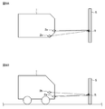
- FIG. 6A is a diagram illustrating an example of an installation position of a distance measurement sensor in a vehicle, and is a diagram illustrating a state viewed from above the vehicle.
- FIG. 6B is a diagram illustrating an example of an installation position of the distance measurement sensor in the vehicle, and is a diagram illustrating a state viewed from a side of the vehicle.
- FIG. 7A is a diagram illustrating an example of a propagation path of a reflected wave by a traveling obstacle such as a wall.
- FIG. 7B is a diagram illustrating an example of a waveform of a transmission signal.
- FIG. 7C is a diagram illustrating an example of a waveform of a reception signal corresponding to a reflected wave by a traveling obstacle.
- FIG. 7D is a diagram illustrating another example of the waveform of the received signal corresponding to the reflected wave from the traveling obstacle.
- FIG. 8A is a diagram illustrating an example of a propagation path of a reflected wave by a road obstacle such as a curb or a road surface obstacle such as a step.
- FIG. 8B is a diagram illustrating an example of a waveform of a transmission signal.
- FIG. 8C is a diagram illustrating an example of a waveform of a reception signal corresponding to a reflected wave from a road obstacle.
- FIG. 8D is a diagram illustrating another example of the waveform of the received signal corresponding to the reflected wave from the road obstacle.
- FIG. 8A is a diagram illustrating an example of a propagation path of a reflected wave by a road obstacle such as a curb or a road surface obstacle such as a step.
- FIG. 8B is a diagram illustrating an example of a waveform of a transmission signal.
- FIG. 8E is a diagram illustrating an example of a waveform of a received signal corresponding to a reflected wave from a road surface obstacle.
- FIG. 8F is a diagram illustrating another example of the waveform of the received signal corresponding to the reflected wave from the road surface obstacle.
- FIG. 9A is an example of the distribution of the reflection points on the YZ plane and the distribution length of the reflection points on the reflection surface of the obstacle when the obstacle is an obstacle on the road in the obstacle detection device according to the first embodiment.
- FIG. FIG. 9B is an example of the distribution of the reflection points on the YZ plane and the distribution length of the reflection points on the reflection surface of the obstacle when the obstacle is a traveling obstacle in the obstacle detection device according to Embodiment 1.
- FIG. 10 is a diagram illustrating an example of a correlation between the distribution length of the reflection points and the height of the obstacle.
- FIG. 11 is a block diagram illustrating a main part of an obstacle detection device according to a modification of the first embodiment.
- FIG. 12A is a diagram illustrating an example of an installation position of a distance measurement sensor in a vehicle, and is a diagram illustrating a state viewed from above the vehicle.
- FIG. 12B is a diagram illustrating an example of an installation position of a distance measurement sensor in a vehicle and an example of a process in which a reflection point extraction unit in an obstacle detection device according to another modification of the first embodiment extracts a position of a reflection point.
- FIG. 5 is a diagram showing a state viewed from a side of the vehicle.
- FIG. 13 is a block diagram illustrating a main part of the obstacle detection device according to the second embodiment.
- FIG. 14 is a flowchart illustrating an example of the operation of the obstacle detection device according to the second embodiment.
- FIG. 15A is a diagram illustrating an example of an installation position of a distance measurement sensor in a vehicle when an obstacle is a traveling obstacle, and is a diagram illustrating a state viewed from above the vehicle.
- FIG. 15B is a diagram illustrating an example of an installation position of the distance measurement sensor in the vehicle when the obstacle is a traveling obstacle, and is a diagram illustrating a state viewed from a side of the vehicle.
- FIG. 15A is a diagram illustrating an example of an installation position of a distance measurement sensor in a vehicle when an obstacle is a traveling obstacle, and is a diagram illustrating a state viewed from above the vehicle.
- FIG. 15B is a diagram illustrating an example of an installation position of the distance measurement sensor in the vehicle when the obstacle is a traveling obstacle, and is
- FIG. 16A is a diagram illustrating an example of an installation position of a distance measurement sensor in a vehicle when the obstacle is a road obstacle or a road surface obstacle, and is a diagram illustrating a state viewed from above the vehicle.
- FIG. 16B is a diagram illustrating an example of an installation position of the distance measurement sensor in the vehicle when the obstacle is a road obstacle or a road surface obstacle, and is a diagram illustrating a state viewed from a side of the vehicle.
- FIG. 17 is a diagram illustrating an example of a sensor pitch, a distance value in a distance measuring sensor, and a directly facing angle.
- FIG. 18 is a block diagram illustrating a main part of the driving support device according to the third embodiment.
- FIG. 19 is a flowchart illustrating an example of the operation of the driving support device according to Embodiment 3.
- FIG. 1 is a block diagram illustrating a main part of the obstacle detection device 100 according to the first embodiment.
- FIG. 2 is a block diagram illustrating a main part of the obstacle detection unit 11 in the obstacle detection device 100 according to the first embodiment.
- FIG. 3 is a block diagram illustrating a main part of the reflection point extraction unit 12 in the obstacle detection device 100 according to the first embodiment.
- the obstacle detection device 100 according to the first embodiment will be described with reference to FIGS.
- the obstacle detection device 100 is connected to a computer network such as a CAN (Controller Area Network) in the vehicle 1.
- the obstacle detection device 100 can appropriately acquire various signals from the network. These signals include, for example, a signal indicating the traveling speed of the vehicle 1 or a signal indicating the yaw rate of the vehicle 1.
- the vehicle 1 is provided with a plurality of distance measurement sensors 2 having different propagation distances.
- the vehicle 1 is provided with two distance measurement sensors 2a and 2b as the plurality of distance measurement sensors 2.
- the distance measuring sensor 2 is constituted by a sensor of a type such as a sonar or a millimeter wave radar, and the two distance measuring sensors 2a and 2b are sensors of the same type.
- ultrasonic waves, radio waves, and the like transmitted and received by the distance measuring sensor 2 are collectively referred to as “search waves”.
- search waves When an obstacle around the vehicle 1 reflects the search wave, the reflected search wave is referred to as a “reflected wave”.
- the search wave and the reflected wave are referred to as “direct waves”.
- the search wave and the reflected wave are referred to as “indirect waves”.
- the two distance measuring sensors 2a and 2b are installed at different positions in the vehicle 1. Further, the two distance measuring sensors 2a and 2b may be arranged such that the direction in which the distance measuring sensors 2a and 2b transmit the search wave and the direction in which the distance measuring sensors 2a and 2b receive the reflected waves are different. Are also oriented in the same direction, such as in front of the vehicle 1. More specifically, for example, the two distance measurement sensors 2a and 2b are provided at different positions in the front nose portion of the vehicle 1, and are set to face the front of the vehicle 1. Note that the distance measurement sensor 2 may be provided toward the rear of the vehicle 1. In principle, there is no problem if the distance measuring sensor 2 is provided in any direction among the four directions of the front, rear, left and right of the vehicle 1. The direction in which the distance measurement sensor 2 is directed in the vehicle 1 is referred to as “the installation direction of the distance measurement sensor 2”.
- the propagation distance is the distance over which the search wave transmitted from the distance measurement sensor 2 propagates until the search wave is reflected by the obstacle, and the distance until the reflection wave reflected from the obstacle is received by the distance measurement sensor 2. With the distance over which the reflected wave propagates. Therefore, that the propagation distances are different means that the propagation distances of the plurality of distance measurement sensors 2 are different.
- the reflected waves of the search waves transmitted by the distance measurement sensors 2a and 2b are received as direct waves by the distance measurement sensors 2a and 2b, respectively.
- the distance measuring sensors 2a and 2b have different propagation distances in the distance measuring sensor 2a and the distance measuring sensor 2b because the distance measuring sensors 2a and 2b are provided at different positions. The above-described propagation distance difference appears significantly for obstacles lower than the mounting height of the distance measurement sensor 2.
- an obstacle having a height enough to contact the bumper portion of the vehicle 1 is referred to as a “running obstacle”.
- the traveling obstacle is, for example, a wall or another parked vehicle.
- obstacles having a height that does not contact the bumper portion of the vehicle 1 and that is high enough to prevent the vehicle 1 from getting over are referred to as “road obstacles”.
- the road obstacle is, for example, a curb or a wheelchair.
- an obstacle having a height lower than that of a road obstacle and having a height enough to allow the vehicle 1 to get over is referred to as a “road obstacle”.
- the road surface obstacle is, for example, a step. That is, the height of the obstacle increases in the order of the road surface obstacle, the road obstacle, and the traveling obstacle.
- the distance measurement sensor 2a receives the reflected wave of the search wave transmitted by the distance measurement sensor 2a as a direct wave
- the distance measurement sensor 2b indirectly receives the reflected wave of the search wave transmitted by the distance measurement sensor 2a.
- the distance measuring sensor 2a receives a reflected wave of the search wave transmitted by the distance measuring sensor 2b as an indirect wave
- the distance measuring sensor 2b receives a reflected wave of the search wave transmitted by the distance measuring sensor 2b as a direct wave. It may be something to do.
- the distance measuring sensors 2a and 2b alternately transmit the search wave by the distance measuring sensor 2a and the distance measuring sensor 2b, and generate the search wave transmitted by either the distance measuring sensor 2a or the distance measuring sensor 2b.
- the reflected wave may be received by both the distance measurement sensor 2a and the distance measurement sensor 2b.
- the distance measuring sensors 2a and 2b may be configured such that each of the distance measuring sensors 2a and 2b receives a reflected wave of the search wave transmitted by the distance measuring sensor 2a or 2b as a direct wave.
- the main part of the obstacle detection device 100 includes an obstacle detection unit 11, a reflection point extraction unit 12, and an obstacle determination unit 13.
- the obstacle detection unit 11 calculates a distance from the distance measurement sensor 2 to an obstacle around the vehicle 1.
- the main part of the obstacle detection unit 11 includes a transmission signal output unit 21, a reception signal acquisition unit 22, and a distance value calculation unit 23.
- the transmission signal output unit 21 sequentially outputs a transmission signal to the distance measurement sensor 2 to cause the distance measurement sensor 2 to sequentially transmit a search wave.
- the transmission signal output section 21 outputs a transmission signal to the distance measurement sensor 2a, thereby causing the distance measurement sensor 2a to transmit a search wave.
- the operation related to the distance measuring sensor 2b is the same as that of the distance measuring sensor 2a, and thus the description is omitted.
- the reception signal acquisition unit 22 acquires information on the reflected wave received by the distance measurement sensor 2 from the distance measurement sensor 2 as a reception signal.
- the reception signal acquisition unit 22 acquires, as a reception signal, information on a reflected wave of a direct wave received by the distance measurement sensor 2a from the distance measurement sensor 2a, and receives the indirect signal received by the distance measurement sensor 2b.
- the information of the reflected wave in the wave is acquired from the distance measurement sensor 2b as a reception signal.
- the distance value calculating unit 23 determines whether or not the distance measuring sensor 2 has received a reflected wave by comparing the intensity of the received signal acquired by the received signal acquiring unit 22 with a predetermined threshold. When it is determined that the distance measurement sensor 2 has received the reflected wave, the distance value calculation unit 23 calculates a distance value indicating the distance from the distance measurement sensor 2 to the obstacle using the TOF. Since the calculation process of the distance value by TOF is known, detailed description is omitted. In the example shown in FIG. 2, the distance value calculation unit 23 calculates the distance value based on the reflected waves received by each of the distance measurement sensors 2a and 2b.
- the obstacle detection unit 11 causes any one of the plurality of ranging sensors 2 to transmit the search wave, obtains the reception signal of the reflected wave from each of the plurality of ranging sensors 2, and obtains the obtained signal.
- a distance value corresponding to each of the plurality of distance measurement sensors 2 is calculated based on each of the received signals.
- a distance value calculated based on a reflected wave received by a certain distance measuring sensor 2 will be described as "distance value in the distance measuring sensor 2".
- “distance value at distance measuring sensor 2a” means a distance value calculated based on a reflected wave received by distance measuring sensor 2a.
- the distance value of the distance measuring sensor 2a is referred to as "distance value Dra”
- the distance value of the distance measuring sensor 2b is referred to as "distance value Drb”.
- the reflection point extraction unit 12 extracts the position of the point where the search wave is reflected (hereinafter, referred to as “reflection point”) using the distance value calculated by the obstacle detection unit 11. That is, the reflection point extraction unit 12 extracts the position of the reflection point based on the reception signals acquired from the plurality of distance measurement sensors 2 provided in the vehicle 1 and having different propagation distances. In the example shown in FIGS. 2 and 3, the reflection point extracting unit 12 calculates the distance values Dra and Drb in the distance measurement sensors 2a and 2b calculated based on the reception signals acquired from the distance measurement sensors 2a and 2b, respectively. To extract the position of the reflection point. The reflection point extracted based on the distance value Dra and the distance value Drb is referred to as “reflection point Rab”.
- the reflection point extraction unit 12 is mainly composed of a reflection point position calculation unit 24, a vehicle position calculation unit 26, and a sensor position calculation unit 27.
- the reflection point position calculation unit 24 calculates the position of the reflection point using the plurality of distance values of the plurality of distance measurement sensors 2 calculated by the distance value calculation unit 23 of the obstacle detection unit 11. In the examples shown in FIGS. 2 and 3, the reflection point position calculation unit 24 calculates the distance value Dra of the distance measurement sensor 2a and the distance value Drb of the distance measurement sensor 2b calculated by the distance value calculation unit 23 of the obstacle detection unit 11. The position of the reflection point Rab is calculated using both. More specifically, the reflection point position calculation unit 24 includes information indicating the position of each of the distance measurement sensors 2a and 2b (hereinafter, referred to as “sensor position”) at the transmission timing of the search wave, and the distance measurement sensors 2a and 2b in the vehicle 1.
- the position of the reflection point Rab is calculated by a so-called "two-circle intersection" based on the information indicating the installation direction of the distance measuring sensor 2b, the distance value Dra of the distance measuring sensor 2a, and the distance value Drb of the distance measuring sensor 2b.
- the position of the reflection point Rab is, for example, an arc whose radius is the distance value Dra on a plane parallel to the front-rear direction of the vehicle 1 (hereinafter, referred to as a “sensor plane”) including the installation positions of the distance measurement sensors 2a and 2b. While drawing, draw an arc whose radius is the distance value Drb.
- the intersection of these two arcs is the position of the reflection point Rab.
- the position of the reflection point Rab is calculated by executing the two-circle intersection processing.
- the positions of the reflection points are, for example, a first axis (hereinafter, referred to as “X axis”) corresponding to the front-rear direction of the vehicle 1, a second axis (hereinafter, referred to as “Y axis”) corresponding to the left and right direction of the vehicle 1. And, it is represented by a coordinate value in a coordinate system (hereinafter, referred to as an “XYZ coordinate system”) in a meter unit by a third axis (hereinafter, referred to as “Z axis”) corresponding to the height direction of the vehicle 1.
- the information indicating the sensor position is output by the sensor position calculation unit 27 described later.
- the information indicating the installation direction of the distance measurement sensors 2a and 2b in the vehicle 1 is stored in the reflection point position calculation unit 24 in advance. Since the two distance measuring sensors 2a and 2b are directed in the same direction as each other, it is sufficient if there is information indicating the installation direction of either the distance measuring sensor 2a or the distance measuring sensor 2b.
- the own vehicle position calculating unit 26 calculates, for example, the position of the vehicle 1 (hereinafter, referred to as “own vehicle position”) at the timing when the distance measurement sensor 2a transmits the search wave.
- a well-known method such as autonomous navigation can be used to calculate the own vehicle position, and a detailed description is omitted.
- the signal used for the autonomous navigation is appropriately acquired from a computer network in the vehicle 1.
- the signals used for the autonomous navigation include, for example, a signal indicating the traveling speed of the vehicle 1 and a signal indicating the yaw rate of the vehicle 1.
- the own vehicle position is represented by, for example, coordinate values in an XYZ coordinate system.
- the sensor position calculator 27 calculates the sensor position from information indicating the position of the vehicle at the timing when the distance measurement sensor 2a transmits the search wave and information indicating the installation positions of the distance measurement sensors 2a and 2b in the vehicle 1. Is what you do.
- the sensor position is represented by, for example, a coordinate value in an XYZ coordinate system.
- the sensor position calculator 27 outputs information indicating the sensor position to the reflection point position calculator 24.
- the information indicating the sensor position is used by the reflection point position calculation unit 24 to calculate the position of the reflection point.
- Information used when the sensor position calculation unit 27 calculates the sensor position, such as information indicating the installation position of each of the distance measurement sensors 2a and 2b in the vehicle 1, is stored in the sensor position calculation unit 27 in advance.
- the obstacle determining unit 13 determines the height of the obstacle using the distribution length of the reflection points calculated based on the positions of the plurality of reflection points extracted by the reflection point extraction unit 12.
- the obstacle discriminating unit 13 extracts the reflection points corresponding to each of the plurality of time points extracted by the reflection point extracting unit 12 based on the reception signals acquired from the plurality of distance measurement sensors 2 at the plurality of time points. Is used to calculate the distribution length of the reflection points based on the position. More specifically, at a first time point, the obstacle determination unit 13 determines the position of the first reflection point extracted by the reflection point extraction unit 12 based on the reception signals acquired from the plurality of distance measurement sensors 2; At a second time point different from the first time point, the distribution of the reflection points based on the position of the second reflection point extracted by the reflection point extraction unit 12 based on the reception signals acquired from the plurality of distance measurement sensors 2 The length is calculated.
- the period between the first time point and the second time point is, for example, 0.1 second.
- 0.1 second is only an example, and the period between the first time point and the second time point may be a longer time period than the period during which the reflected wave can be uniquely specified as a reflected wave in a certain search wave.
- the positions of the plurality of reflection points are not limited to the positions of the reflection points at the two time points of the first and second time points, and may be the positions of the reflection points at three or more time points.
- the obstacle determining unit 13 determines the reflection value extracted based on the distance value Dra and the distance value Drb calculated based on the reception signal obtained from each of the distance measurement sensors 2a and 2b at a certain time.
- the height of the obstacle is determined using the distribution length of the reflection points calculated based on the position of the point Rab and the position of the reflection point Rab extracted in the same manner as described above at a time different from the above-described certain time. To do. For example, when the number of reflection points exceeds a predetermined number, the obstacle determination unit 13 calculates the distribution length of the reflection points.
- the predetermined number is stored in the obstacle determining unit 13 in advance.
- the obstacle determining unit 13 determines the type of the obstacle by comparing the distribution length of the reflection points at the plurality of reflection points with a predetermined threshold. More specifically, the obstacle determination unit 13 determines whether the height of the obstacle is one of a road surface obstacle, a road obstacle, and a traveling obstacle. Here, the road surface obstacle, the road obstacle, and the traveling obstacle have different heights from each other. Therefore, the obstacle discrimination unit 13 determines whether the obstacle is one of a road surface obstacle, a road obstacle, and a traveling obstacle, because the obstacle has any one of three heights. This is to determine if there is any. That is, the obstacle determination unit 13 determines the height of the obstacle by determining the type of the obstacle.
- the details of the process of determining the type of the obstacle by the obstacle determining unit 13, that is, the process of determining the height of the obstacle will be described later.
- the obstacle determination performed by the obstacle determination unit 13 is not limited to the three types of the road surface obstacle, the road obstacle, and the traveling obstacle, and the type can be increased or decreased. It is also possible to detect the height of the obstacle instead of the type of the obstacle. These can be easily understood from FIG. 10 and the like which will be described later.
- FIGS. 4A and 4B are diagrams illustrating an example of a hardware configuration of a main part of the obstacle detection device 100 according to the first embodiment. With reference to the figure, a hardware configuration of a main part of the obstacle detection device 100 according to the first embodiment will be described.
- the obstacle detection device 100 is configured by a computer, and the computer has a processor 41 and a memory 42.
- the memory 42 stores a program for causing the computer to function as the obstacle detection unit 11, the reflection point extraction unit 12, and the obstacle determination unit 13.
- the processor 41 reads and executes the program stored in the memory 42, the functions of the obstacle detection unit 11, the reflection point extraction unit 12, and the obstacle determination unit 13 are realized.
- the obstacle detection device 100 may include a processing circuit 43.
- the functions of the obstacle detection unit 11, the reflection point extraction unit 12, and the obstacle determination unit 13 may be realized by the processing circuit 43.
- the obstacle detection device 100 may include a processor 41, a memory 42, and a processing circuit 43 (not shown). In this case, some of the functions of the obstacle detection unit 11, the reflection point extraction unit 12, and the obstacle determination unit 13 are realized by the processor 41 and the memory 42, and the remaining functions are realized by the processing circuit 43. It may be something.
- the processor 41 employs, for example, a CPU (Central Processing Unit), a GPU (Graphics Processing Unit), a microprocessor, a microcontroller, or a DSP (Digital Signal Processor).
- a CPU Central Processing Unit
- GPU Graphics Processing Unit
- microprocessor a microcontroller
- DSP Digital Signal Processor
- the memory 42 uses, for example, a semiconductor memory or a magnetic disk. More specifically, the memory 42 includes a RAM (Random Access Memory), a ROM (Read Only Memory), a flash memory, an EPROM (Erasable Programmable Read Memory Only), and an EEPROM (Electrical Memory). State @ Drive) or HDD (Hard @ Disk @ Drive) or the like.
- RAM Random Access Memory
- ROM Read Only Memory
- flash memory an EPROM (Erasable Programmable Read Memory Only)
- EEPROM Electrical Memory
- State @ Drive or HDD (Hard @ Disk @ Drive) or the like.
- the processing circuit 43 may be, for example, an ASIC (Application Specific Integrated Circuit), a PLD (Programmable Logic Device), an FPGA (Field-Programmable Gate Array), or an SoC (Sig-Leg-Site-Ligger-Site-License-Sy-Lag-Site-Ligger-Site-License-Site-License-Site-License-Site-License-Site-Legacy-Sig-System). Is used.
- FIG. 5 is a flowchart illustrating an example of the operation of the obstacle detection device 100 according to the first embodiment.
- the operation of the obstacle detection device 100 according to the first embodiment will be described with reference to the flowchart.
- the obstacle detection device 100 repeatedly executes the processing shown in the flowchart.
- the obstacle detection device 100 searches for a distance measuring sensor 2 that is different from the distance measuring sensor 2 that transmitted the search wave most recently among the plurality of distance measuring sensors 2. Have the waves transmit.
- the obstacle detection unit 11 calculates the distance of the obstacle around the vehicle 1 from the distance measurement sensor 2 by causing the distance measurement sensor 2 to transmit a search wave. More specifically, for example, when the obstacle detection unit 11 causes the distance measurement sensor 2a to transmit a search wave, the distance measurement sensor 2a acquires a received signal of a reflected wave as a direct wave, and the distance measurement sensor 2b A received signal of a reflected wave is obtained as a wave. The obstacle detection unit 11 calculates distance values Dra and Drb in the distance measurement sensors 2a and 2b based on the received signal.
- Step ST2 the reflection point extraction unit 12 performs the reflection point Rab by two-circle intersection processing based on the distance value Dra and the distance value Drb in each of the distance measurement sensors 2a and 2b calculated by the obstacle detection unit 11. Extract the position of.
- the obstacle determining unit 13 determines whether the number of reflection points is equal to or more than a predetermined number.
- the predetermined number is a number of at least 2 or more, and here is 10 as an example.
- step ST3 the obstacle detection device 100 returns to step ST1 until the number of reflection points reaches a predetermined value.
- the obstacle detection device 100 searches for a distance measurement sensor 2 different from the distance measurement sensor 2 that transmitted the search wave most recently among the plurality of distance measurement sensors 2. Have the waves transmit. More specifically, for example, when returning to the process of step ST1, the obstacle detecting unit 11 transmits the search wave to the distance measurement sensor 2b if the distance measurement sensor 2a has recently transmitted the search wave.
- the distance measuring sensor 2b acquires a received signal of the reflected wave as a direct wave
- the distance measuring sensor 2a acquires a received signal of the reflected wave as an indirect wave. If the distance measurement sensor 2b has transmitted the search wave immediately, the distance measurement sensor 2a transmits the search wave, and the distance measurement sensor 2a obtains the reception signal of the reflected wave as a direct wave. Acquires a received signal of a reflected wave as an indirect wave. If the number of reflection points is 10 or more (step ST3: YES), the obstacle detection device 100 performs the process of step ST4.
- step ST4 the obstacle determination unit 13 calculates the distribution length of the reflection points based on the positions of the plurality of reflection points extracted by the reflection point extraction unit 12.
- the obstacle determining unit 13 determines the type of the obstacle using the calculated distribution length of the reflection points.
- the determination of the obstacle is not limited to the determination of the type of the obstacle, but may be the determination of the height of the obstacle, that is, the detection of the obstacle.
- the obstacle detection device 100 ends the processing of the flowchart. The details of the process of determining the type of the obstacle and the process of determining the height of the obstacle by the obstacle determining unit 13 will be described later.
- the reflection point extraction unit 12 may discard the information indicating the position of the reflection point extracted by the reflection point extraction unit 12 before the predetermined period.
- the obstacle determining unit 13 does not include the reflection points extracted by the reflection point extraction unit 12 before the predetermined period in the number of the plurality of reflection points. Is also good.
- the obstacle determining unit 13 uses the distribution length of the reflection points at the plurality of reflection points extracted by the reflection point extraction unit 12 within a predetermined period to obtain an obstacle. May be determined.
- the above-mentioned predetermined period is, for example, 3 seconds.
- the predetermined period may be calculated based on the speed of the vehicle 1.
- the reflection point extracted before 3 seconds may be a reflection point on another obstacle different from the obstacle whose height is currently determined. Therefore, with this configuration, the obstacle detection device 100 can improve the accuracy of the obstacle height determination performed by the obstacle determination unit 13.
- the obstacle determining unit 13 determines the position of the reflection point newly extracted by the reflection point extraction unit 12 and the position of the reflection point extraction unit 12 within a predetermined period. If the position of the reflection point is farther than a predetermined distance, a process of invalidating the information indicating the position of the reflection point that has been extracted by the reflection point extraction unit 12 so far may be performed.
- the predetermined period is, for example, 3 seconds.
- the predetermined distance is, for example, 1 m. The predetermined period and the predetermined distance may be calculated based on the speed of the vehicle 1.
- the distance measurement sensor 2 may be another obstacle different from the obstacle detected so far. Therefore, with this configuration, the obstacle detection device 100 can improve the accuracy of the obstacle height determination performed by the obstacle determination unit 13.
- FIG. 6A is a diagram illustrating an example of an installation position of the distance measurement sensors 2a and 2b in the vehicle 1, and is a diagram illustrating a state viewed from above the vehicle 1.
- FIG. 6B is a diagram illustrating an example of an installation position of the distance measurement sensors 2a and 2b in the vehicle 1, and is a diagram illustrating a state viewed from a side of the vehicle 1.
- the vehicle 1 is provided with distance measuring sensors 2a and 2b having different propagation distances.
- the distance measuring sensors 2a and 2b are installed at different positions in the vehicle 1, and are installed in the vehicle 1 in directions in which the vehicle 1 moves forward.
- the usual arrangement of the distance measuring sensors 2 is omitted, although two are arranged on each of the left and right sides with respect to the center of the vehicle as a symmetry axis, that is, four in total. Further, four of them are arranged not only in front of the vehicle 1 but also in the rear of the vehicle 1, but illustration is omitted here.
- FIG. 1 the vehicle 1 is provided with distance measuring sensors 2a and 2b having different propagation distances.
- the distance measuring sensors 2a and 2b are installed at different positions in the vehicle 1, and are installed in the vehicle 1 in directions in which the vehicle 1 moves forward.
- the usual arrangement of the distance measuring sensors 2 is omitted, although two are arranged on each of the left and right sides with respect to the center of the vehicle as a symmetry axis, that
- the distance measuring sensors 2a and 2b are arranged in all the axial directions of the X axis (the longitudinal direction of the vehicle 1), the Y axis (the lateral direction of the vehicle 1), and the Z axis (the height direction of the vehicle 1).
- the distance measuring sensors 2a and 2b may be installed at different positions as long as the distance measuring sensors 2a and 2b have different propagation distances.
- Y-axis and Z-axis at least in one axis direction.
- an arrow extending from the vehicle 1 toward the obstacle S indicates an example of a propagation path of a search wave transmitted by the distance measurement sensor 2a.
- Arrows extending from the obstacle S toward the vehicle 1 show examples of the trajectories of the reflected waves of the direct wave received by the distance measurement sensor 2a and the indirect wave received by the distance measurement sensor 2b. Further, an example of the position of the reflection point R extracted by the reflection point extraction unit 12 by the two-circle intersection processing is indicated by a cross. The same applies to the propagation path of the search wave transmitted by the distance measurement sensor 2b.
- FIG. 7A shows an example of the propagation path of the reflected wave RW due to a traveling obstacle such as a wall.
- FIG. 7B shows an example of the waveform of the transmission signal TS.
- FIG. 7C illustrates an example of the waveform of the reception signal RS corresponding to the reflected wave RW due to the traveling obstacle.
- FIG. 7D shows another example of the waveform of the reception signal RS corresponding to the reflected wave RW due to the traveling obstacle.
- FIG. 8A shows an example of a propagation path of the reflected wave RW due to a road obstacle such as a curb or a road obstacle such as a step.
- FIG. 8B shows an example of the waveform of the transmission signal TS.
- FIG. 8C shows an example of the waveform of the received signal RS corresponding to the reflected wave RW due to an obstacle on the road.
- FIG. 8D shows another example of the waveform of the received signal RS corresponding to the reflected wave RW due to the obstacle on the road.
- FIG. 8E shows an example of the waveform of the reception signal RS corresponding to the reflected wave RW due to the road surface obstacle.
- FIG. 8F shows another example of the waveform of the received signal RS corresponding to the reflected wave RW due to the road surface obstacle.
- the transmission signal output unit 21 outputs the transmission signal TS to the distance measurement sensor 2 so that the distance measurement sensor 2 transmits the search wave SW.
- the search wave SW propagates in the air while gradually spreading, the propagation path (so-called “path”) from the transmission of the search wave SW by the distance measuring sensor 2 to the reception of the reflected wave RW by the distance measurement sensor 2.
- path there are a plurality. For example, there is a path that is reflected once by the obstacle S and returns to the distance measurement sensor 2. There is also a path that is reflected once by the road G and then reflected once by the obstacle S and returns to the distance measurement sensor 2. These paths include paths having different path lengths.
- the reflected wave RW becomes a composite wave Rw due to interference of a plurality of waves rw corresponding to these paths.
- the received signal RS is a composite signal of a plurality of signals rs corresponding to the plurality of waves rw.
- the path changes according to the uneven shape of the road G, the vibration of the vehicle 1, and the uneven shape of a surface portion (hereinafter, referred to as a “reflecting surface portion”) of the obstacle S that reflects the search wave SW.
- the waveform changes, and the waveform of the received signal RS also changes. For this reason, when a plurality of reflected waves RW due to the same obstacle S are received by the distance measurement sensor 2, the waveforms of the plurality of reflected waves RW have variations, and the plurality of reflected waves RW Also has a variation in the waveform of the received signal RS corresponding to.
- the reception intensity of the reflected wave RW is large because the area of the reflection surface portion is larger than when the obstacle S is a road obstacle (FIG. 8). (That is, the strength of the received signal RS) increases.
- the variation in the waveform of the reflected wave RW increases, and the variation in the waveform of the reception signal RS also increases.
- the reception intensity of the reflected wave RW is larger than that when the obstacle S is a road obstacle (not shown). (That is, the strength of the received signal RS) increases.
- the variation in the waveform of the reflected wave RW increases, and the variation in the waveform of the reception signal RS also increases.
- the distance value calculated by the obstacle detection unit 11 based on the received signal RS having the variation has a variation. Therefore, the variation in the calculated distance value has a correlation with the height of the obstacle S. Have. Further, the position coordinates of the reflection point R extracted by the two-circle intersection processing using the distance value having the variation by the reflection point extracting unit 12 also vary according to the variation of the distance value. Therefore, the variation in the extracted reflection points R also has a correlation with the height of the obstacle S.
- the distribution length of the reflection points R is calculated from the above-described range of the dispersion of the reflection points.
- FIG. 9 is a diagram showing an example of the distribution of the reflection points R and the distribution length of the reflection points in the distance measuring sensors 2a and 2b shown in FIG.
- the reflection points R are extracted on the sensor plane where two circles intersect. Therefore, as the distribution length of the reflection points, the distribution length of the reflection points on the sensor plane or the distribution length of the reflection points on the sensor plane is determined by the Z axis of the YZ plane (the height direction of the vehicle 1), that is, the vertical direction. There is a distribution length of the reflection points projected on the surface, and any of them may be used.
- FIG. 9 is a diagram showing an example of the distribution of the reflection points R and the distribution length of the reflection points in the distance measuring sensors 2a and 2b shown in FIG.
- the reflection points R are extracted on the sensor plane where two circles intersect. Therefore, as the distribution length of the reflection points, the distribution length of the reflection points on the sensor plane or the distribution length of the reflection points on the sensor plane is determined by the Z axis of the YZ plane (the height
- FIG. 9A is a diagram illustrating an example of the distribution of the reflection points R on the YZ plane and the distribution length of the reflection points on the reflection surface of the obstacle S when the obstacle S is an obstacle on the road.
- FIG. 9B is a diagram illustrating an example of the distribution of the reflection points R on the YZ plane and the distribution length of the reflection points on the reflection surface of the obstacle S when the obstacle S is a traveling obstacle.
- the horizontal axis direction is the left-right direction of the vehicle 1, that is, the Y-axis direction.
- the vertical axis direction is the height direction of the vehicle 1, that is, the Z axis direction.
- the reflection surface of the obstacle S exists on a YZ plane orthogonal to the X axis, which is the front-back direction of the vehicle 1.
- X marks indicate the positions of the reflection points R extracted by the reflection point extraction unit 12 projected on the YZ plane on the reflection surface of the obstacle S.
- the reflection point R extracted by the two-circle intersection processing is located on or near the reflection surface.
- the distribution length D1 of the reflection points indicates the distribution length of the reflection points on the sensor plane when the obstacle S is an obstacle on the road.
- the distribution length D2 of the reflection points is obtained by projecting the distribution length D1 of the reflection points on the sensor plane when the obstacle S is an obstacle on the road onto the Z axis of the YZ plane (in the height direction of the vehicle 1).
- the distribution length of the reflection points is shown.
- the distribution lengths D1 and D2 of the reflection points are calculated from the two reflection points R that are the farthest apart on the sensor plane.
- the distribution length D3 of the reflection points indicates the distribution length of the reflection points on the sensor plane when the obstacle S is a traveling obstacle.
- the distribution length D4 of the reflection points is obtained by projecting the distribution length D3 of the reflection points on the sensor plane when the obstacle S is a running obstacle onto the Z axis of the YZ plane (in the height direction of the vehicle 1).
- the distribution length of the reflection points is shown.
- the distribution lengths D3 and D4 of the reflection points are calculated based on, for example, two reflection points R which are the farthest apart on the sensor plane. Comparing the distribution length D1 of the reflection point and the distribution length D3 of the reflection point, and the distribution length D2 of the reflection point and the distribution length D4 of the reflection point, the reflection point when the obstacle S is a traveling obstacle Are longer than the distribution lengths D1 and D2 of the reflection points when the obstacle S is an obstacle on the road.
- FIG. 10 is a diagram illustrating an example of a correlation between the distribution length of the reflection points and the height of the obstacle.
- the horizontal axis indicates the distribution length of the reflection points
- the vertical axis indicates the height of the obstacle.
- the obstacle determining unit 13 compares the predetermined first threshold value Dth1 and second threshold value Dth2 with the distribution length of the reflection points, and determines that the obstacle is a traveling obstacle, a road obstacle, or a road obstacle. It is determined whether the type is any of the above.
- the first threshold Dth1 is a value smaller than the second threshold Dth2.
- the obstacle is determined to be a road surface obstacle. If the distribution length of the reflection points at the plurality of reflection points is equal to or greater than the first threshold value Dth1 and less than the second threshold value Dth2, the obstacle is determined to be a road obstacle. When the distribution length of the reflection points at the plurality of reflection points is equal to or greater than the second threshold value Dth2, the obstacle is determined to be a traveling obstacle.
- the obstacle S illustrated in FIG. An obstacle can be determined. If the distribution length D3 of the reflection points shown in FIG. 9B or the distribution length D4 of the reflection points is greater than or equal to the second threshold value Dth2, the obstacle S shown in FIG. 9B is determined to be a traveling obstacle. Can be. Practically, it is required to determine whether the obstacle S is a road surface obstacle, a road obstacle, or a traveling obstacle.
- the obstacle determining unit 13 can determine the type of the obstacle S based on the distribution length of the reflection points. In FIG.
- the threshold when the threshold is only the first threshold Dth1, it can be determined whether or not the vehicle 1 is a road obstacle that the vehicle 1 can get over.
- the type of the obstacle S can be determined more finely.
- the height of the obstacle S can be detected based on the distribution length of the reflection points. That is, the determination is used not only to classify the type of the obstacle S but also to detect the height of the obstacle S.
- the obstacle detection device 100 extracts the position of the reflection point based on the reception signals obtained from the plurality of distance measurement sensors 2 provided in the vehicle 1 and having different propagation distances.
- a point extraction unit 12, an obstacle determination unit 13 that determines the height of the obstacle S using the distribution length of the reflection points calculated based on the positions of the plurality of reflection points extracted by the reflection point extraction unit 12, , Equipped.
- the obstacle detection device 100 can determine the height of the obstacle S with less restrictions on design or with high accuracy. Further, by preparing the first threshold value Dth1 and the second threshold value Dth2, it is possible to determine in which range the height of the detected obstacle S falls among the road surface obstacle, the road obstacle, and the traveling obstacle.
- the distribution length of the reflection points is calculated by, for example, the two reflection points that are the farthest apart on the sensor plane.
- the distribution length is not limited to this.
- the distribution length of the reflection point is obtained by projecting the position of the reflection point R extracted by the reflection point extraction unit 12 on the YZ plane on the reflection surface of the obstacle S, and the distance is the shortest in any direction on the YZ plane. It may be calculated by two separated reflection points. Also, the distribution length of the reflection points does not necessarily need to be calculated from the two reflection points that are farthest apart.
- An obstacle detection device 100 according to a modification of the first embodiment will be described with reference to FIG. Descriptions that are the same as those described in the above embodiments will be omitted.
- the obstacle discriminating unit 13 in the obstacle detecting device 100 according to the first embodiment is configured such that the reflecting point extracting unit 12 extracts the plurality of time points based on the reception signals acquired from the distance measurement sensors 2a and 2b at the plurality of time points. Is to calculate the distribution length of the reflection points based on the reflection points corresponding to.
- the obstacle discriminating unit 13 in the obstacle detecting device 100 according to the modification of the first embodiment uses the reflection point extracting unit 12 based on the reception signals acquired from the plurality of distance measurement sensors 2 at the same time. Calculates the distribution length of the reflection points based on the plurality of reflection points extracted by.
- FIG. 11 is a block diagram illustrating a main part of an obstacle detection device 100 according to a modification of the first embodiment.
- three distance measuring sensors 2a, 2b, and 2c are provided in the vehicle 1 as the plurality of distance measuring sensors 2.
- the distance measuring sensor 2 is constituted by a sensor of a type such as a sonar or a millimeter wave radar, and the three distance measuring sensors 2a, 2b, and 2c are sensors of the same type.
- the distance measurement sensor 2a receives a reflected wave of the search wave transmitted by the distance measurement sensor 2a as a direct wave
- the distance measurement sensors 2b and 2c receive reflected waves of the search wave transmitted by the distance measurement sensor 2a.
- the three distance measuring sensors 2a, 2b, 2c are different from each other in the installation position in the vehicle 1.
- the three distance measuring sensors 2a, 2b, and 2c include a direction in which the distance measuring sensor 2a transmits the search wave and a direction in which the reflected wave is received, and the distance measuring sensor 2b and the distance measuring sensor 2c receive the reflected wave.
- the directions are all set in the same direction. More specifically, the three distance measurement sensors 2a, 2b, 2c are provided at different positions in the front nose portion of the vehicle 1, and are set to face the front of the vehicle 1, for example. .
- a plurality of vehicles 1 may be installed at different positions on the rear part of the vehicle 1 toward the rear of the vehicle 1. In principle, there is no problem if it is provided in any one of the four directions of front, rear, left and right of the vehicle 1.
- a combination of the three distance measurement sensors 2a, 2b, and 2c forms a plurality of distance measurement sensors 2 having different propagation distances.
- the two ranging sensors 2a and 2b receive the reflected wave of the search wave transmitted by the ranging sensor 2a as a direct wave and the ranging sensor 2b receives the reflected wave as an indirect wave, respectively.
- a plurality of distance measurement sensors 2 having different propagation distances are configured.
- the two ranging sensors 2a and 2c receive the reflected wave of the search wave transmitted by the ranging sensor 2a as the direct wave and the ranging sensor 2c receives the reflected wave as the indirect wave, respectively.
- a plurality of distance measurement sensors 2 having different propagation distances are configured. Further, by disposing the distance measuring sensors 2b and 2c for receiving the indirect waves at different positions, the distance measuring sensors 2b and 2c can form a plurality of distance measuring sensors 2 having different propagation distances. .
- the obstacle detection unit 11 calculates a distance value in each of the distance measurement sensors 2a, 2b, 2c based on a reception signal acquired from each of the distance measurement sensors 2a, 2b, 2c.
- the distance values at the distance measuring sensors 2a, 2b, 2c are respectively referred to as distance values Dra, Drb, Drc.
- the reflection point extracting unit 12 measures, for example, the reflection point Rab based on the distance values Dra and Drb in the distance measurement sensors 2a and 2b, the Rac based on the distance values Dra and Drc in the distance measurement sensors 2a and 2c, and The position of the reflection point Rbc is extracted based on the distance values Drb and Drc at the distance sensors 2b and 2c, respectively.
- the reflection point extraction unit 12 selects any two of the distance values Dra, Drb, and Drc calculated based on the reception signals obtained from the three distance measurement sensors 2a, 2b, and 2c having different propagation distances. By combining the distance values, the positions of the three reflection points can be extracted.
- the obstacle determining unit 13 determines the height of the obstacle using the distribution length of the reflection points calculated based on the positions of the plurality of reflection points extracted based on the reception signal acquired at the same time. .
- the obstacle detection device 100 can determine the number of reflection points based on the positions of the plurality of reflection points extracted based on the reception signal acquired at the same time. Since the distribution length can be calculated, there is no need to calculate the distribution length of the reflection points based on the reflection points corresponding to a plurality of time points, and the period until the distribution length of the reflection points is calculated is shortened. it can.
- the number of the distance measurement sensors 2 is three as one example of the distance measurement sensors 2a, 2b, and 2c, but is not limited thereto.
- the number of the distance measuring sensors 2 may be four or more as long as the distance measuring sensors 2 have different propagation distances. As a result, the number of reflection points obtained can be increased, and the detection accuracy of the obstacle S can be improved.
- An obstacle detection device 100 according to another modification of the first embodiment will be described with reference to FIG. Descriptions that are the same as those described in the above embodiments will be omitted.
- the reflection point extraction unit 12 in the obstacle detection device 100 performs two-circle intersection processing using information indicating the installation positions of the plurality of distance measurement sensors 2 in the vehicle 1 to determine the position of the reflection point. It was to be extracted.
- the reflection point extraction unit 12 in the obstacle detection device 100 according to another modification of the first embodiment determines that the installation position of the plurality of distance measurement sensors 2 provided on the vehicle 1 is the height of the vehicle 1 If the distances are the same in the directions and are different in the front-back direction of the vehicle 1, the two-circle intersection processing is performed assuming that any of the distance measurement sensors 2 is at the virtual installation position, and the position of the reflection point is extracted. It is. Note that the term “same” in the height direction in the height direction is not limited to the strictly same position, but includes substantially the same position.
- FIG. 12A is a diagram illustrating an example of an installation position of the distance measurement sensors 2 a and 2 b in the vehicle 1, and is a diagram illustrating a state viewed from above the vehicle 1.
- FIG. 12A is a view of the vehicle 1 viewed from the Z-axis direction which is the height direction of the vehicle 1 in the XYZ coordinate system set in the same manner as that shown in FIG.
- FIG. 12B illustrates an example of the installation positions of the distance measurement sensors 2a and 2b in the vehicle 1, and the reflection point extraction unit 12 in the obstacle detection device 100 according to another modification of the first embodiment extracts the positions of the reflection points.
- FIG. 4 is a diagram illustrating an example of a process, and is a diagram illustrating a state when viewed from a side of the vehicle 1.
- FIG. 12B is a diagram of the vehicle 1 viewed from the Y-axis direction which is the left-right direction of the vehicle 1 in the XYZ coordinate system set in the same manner as that shown in FIG.
- the two distance measuring sensors 2a and 2b have the same installation position in the vehicle 1 in the Z-axis direction (the height direction of the vehicle 1) and differ at least in the X-axis direction that is the front-back direction of the vehicle 1. .
- the direction in which the distance measuring sensor 2a transmits the search wave and the direction in which the reflected wave is received is the same as the direction in which the distance measuring sensor 2b receives the reflected wave. It is installed facing. More specifically, the two distance measuring sensors 2a and 2b are, for example, at the same position in the Z-axis direction (the height direction of the vehicle 1) in the front nose portion of the vehicle 1, and at least in the X-axis direction (the vehicle 1).
- Front-rear direction of the vehicle 1 (Front-rear direction of the vehicle 1), and is further set to face forward of the vehicle 1.
- a plurality of vehicles 1 may be installed at different positions on the rear part of the vehicle 1 toward the rear of the vehicle 1. In principle, there is no problem if it is provided in any one of the four directions of front, rear, left and right of the vehicle 1.
- the X coordinate is Xa
- the Y coordinate is Ya
- the Z coordinate is Za
- the X coordinate is Xb
- the Y coordinate is Yb
- the Z coordinate is Zb.
- Za Zb (or Za ⁇ Zb)
- the installation positions of the distance measurement sensors 2a and 2b in the vehicle 1 are different in the X-axis direction (the front-back direction of the vehicle 1)
- Xa ⁇ Xb The distance ⁇ Xab between the distance measurement sensors 2a and 2b in the X-axis direction (the front-back direction of the vehicle 1) is obtained as an absolute value of Xa-Xb.
- the reflection point extracting unit 12 firstly sets a plane parallel to the left-right direction of the vehicle including the installation positions of the plurality of distance measurement sensors, that is, a sensor plane in the X-axis direction, including the installation position of the distance measurement sensor 2a.
- the reflection point extracting unit 12 sets the distance measuring sensor 2b at a position on the virtual vertical plane determined according to the distance ⁇ Xab between the distance measuring sensors 2a and 2b in the X-axis direction (the front-back direction of the vehicle 1). Assuming that they are virtually provided, the position of the reflection point is extracted by two-point intersection processing.
- the distance measurement sensor 2bv is a distance measurement sensor 2b virtually provided on a virtual vertical plane. More specifically, for example, the distance measurement sensor 2bv is provided at a position separated from the distance measurement sensor 2a by a distance ⁇ Xab in the Z-axis direction (the height direction of the vehicle 1) on the virtual vertical plane.
- the reflection point extracting unit 12 executes the two-circle intersection processing on the virtual vertical plane using the installation positions of the distance measurement sensor 2a and the distance measurement sensor 2bv, and the distance value Dra and the distance value Drb, thereby obtaining the reflection point. Extract.
- the position on the virtual vertical plane according to the distance ⁇ Xab determined by the reflection point extraction unit 12 has been described as a position separated from the distance measurement sensor 2a by the distance ⁇ Xab in the Z-axis direction (the height direction of the vehicle 1), , This is an example, and is not limited to this.
- the position on the virtual vertical plane according to the distance ⁇ Xab determined by the reflection point extraction unit 12 is determined based on the distance ⁇ Xab, the distance value Dra in the distance measurement sensor 2a, and the installation position of the distance measurement sensor 2a. Is also good.
- the installation positions of the plurality of distance measurement sensors 2 are the same in the height direction of the vehicle 1,
- the plane is a plane obtained by inclining a plane parallel to the left-right direction of the vehicle 1 including the installation positions of the plurality of distance measurement sensors 2.
- a virtual vertical plane orthogonal to the left-right direction of the vehicle 1 including the installation positions of the two distance measurement sensors 2 is specified, and another distance measurement among the plurality of distance measurement sensors 2 is performed according to the distance between the plurality of distance measurement sensors 2. Assuming that the sensor 2 is virtually provided on a virtual vertical plane, the position of the reflection point is configured to be extracted.
- the obstacle detection device 100 according to another modification of Embodiment 1 has different propagation distances even when the plurality of distance measurement sensors 2 are installed at the same height.
- the height of the obstacle S ahead in the traveling direction can be determined with high accuracy by regarding the plurality of sensors. Therefore, compared to the obstacle detection device 100 according to the first embodiment, the degree of freedom of the installation position of the distance measurement sensor 2 can be increased.
- Embodiment 2 FIG. An obstacle detection device 100a according to the second embodiment will be described.
- the obstacle detection device 100a according to the second embodiment differs from the obstacle detection device 100 according to the first embodiment in that a facing determination unit 14 is added.
- FIG. 13 is a block diagram illustrating a main part of the obstacle detection device 100a according to the second embodiment.
- an obstacle detection device 100a according to the second embodiment will be described.
- the same reference numerals are given to the same blocks as the blocks shown in FIG. 1, and the description will be omitted.
- the vehicle 1 is provided with four distance measuring sensors 2a, 2b, 2c, and 2d as the plurality of distance measuring sensors 2.
- the four distance measuring sensors 2a, 2b, 2c, 2d are provided in a front nose portion of the vehicle 1, more specifically, in a front bumper portion, as shown in FIG. I have.
- the installation position of the distance measurement sensor 2 is not limited to the front part of the vehicle 1. If it is desired to detect an obstacle S at the rear part, four distance measurement parts are provided at the rear part of the vehicle 1.
- a sensor 2 can be provided.
- the main part of the obstacle detection device 100a includes an obstacle detection unit 11, a reflection point extraction unit 12, an obstacle determination unit 13, and a facing determination unit 14.
- the obstacle detection unit 11 calculates the distance value in each of the plurality of distance measurement sensors 2 by sequentially transmitting the search waves to the distance measurement sensors 2a to 2d.
- the distance values of the distance measuring sensors 2a to 2d are referred to as distance values Dra, Drb, Drc, and Drd, respectively. Since the second embodiment is for determining whether or not the vehicle 1 is directly facing the obstacle S, the search wave is transmitted first in the arrangement of the distance measurement sensor 2 shown in FIG. The distance measurement is performed from the distance measurement sensor 2b or the distance measurement sensor 2d that is the distance measurement sensor 2, and then the distance measurement sensor 2d or the distance measurement sensor 2b that is the other outer distance measurement sensor 2, and the distance measurement sensor that is the inner distance measurement sensor 2.
- the outer distance measurement sensor 2b receives a reflected wave of the search wave transmitted by the distance measurement sensor 2b as a direct wave
- the distance measurement sensors 2a, 2c, and 2d reflect the search wave transmitted by the distance measurement sensor 2b.
- Receive waves as indirect waves.
- the obstacle detecting unit 11 calculates distance values Dra, Drb, Drc, and Drd in the distance measuring sensors 2a, 2b, 2c, and 2d based on the received signals of the respective reflected waves.
- the reflection point extracting unit 12 extracts a plurality of reflection points by a two-circle intersection process using the distance values Dra, Drb, Drc, and Drd.
- the search wave is transmitted from the other outer distance measuring sensor 2d.
- the distance measurement sensor 2d receives the reflected wave of the search wave transmitted by the distance measurement sensor 2d as a direct wave
- the distance measurement sensors 2c, 2a, and 2b receive the reflected wave of the search wave transmitted by the distance measurement sensor 2d as an indirect wave. Receive as.
- a plurality of reflection points are extracted by the obstacle detection unit 11 and the reflection point extraction unit 12 based on the received signals of the respective reflected waves.
- the search waves are sequentially transmitted from the inner distance measuring sensors 2a and 2c, and the reflection points are extracted.
- the process returns to the distance measurement sensor 2 that transmitted the search wave first, and the same may be repeated thereafter.
- the internal configuration of the obstacle detection unit 11 is the same as that described in the first embodiment with reference to FIG.
- the description will be given on the assumption that the distance measurement sensors 2a to 2d sequentially transmit search waves.
- any one of the distance measurement sensors 2a to 2d for example, the distance measurement sensor 2c transmits a search wave, and the distance measurement sensor 2c receives the search wave.
- the reflection point may be extracted using the direct wave thus obtained and the indirect waves received by the distance measuring sensors 2a, 2b and 2d.
- FIG. 15 shows how the outer distance measuring sensor 2 transmits and receives a search wave.
- FIG. 15 illustrates two transmission / reception states at the same time, that is, when the search wave of the distance measurement sensor 2b is transmitted and received and when the search wave of the distance measurement sensor 2d is transmitted and received.
- the reflected wave from the distance measuring sensor 2b is depicted as if it were received only by the distance measuring sensor 2b (direct wave) and the distance measuring sensor 2a (indirect wave). However, actually, the reflected wave of the distance measuring sensor 2b is also received by the distance measuring sensor 2c (indirect wave) and the distance measuring sensor 2d (indirect wave), but is omitted here for the sake of clarity.
- the reflected wave of the distance measuring sensor 2d includes the distance measuring sensor 2d (direct wave), the distance measuring sensor 2c (indirect wave), and the distance measuring sensor 2a (indirect wave). And the distance measurement sensor 2b (indirect wave).
- the reflection point extraction unit 12 determines the position of the reflection point Rab using the distance values Dra and Drb in the distance measurement sensors 2a and 2b calculated by the obstacle detection unit 11, and the reflection point Rab in each of the distance measurement sensors 2c and 2d.
- the position of the reflection point Rcd is extracted using the distance values Drc and Drd.
- the internal configuration of the reflection point extracting unit 12 is the same as that described in the first embodiment with reference to FIG.
- the facing-facing determining unit 14 determines whether or not the distance measuring sensor 2 faces the obstacle S. The details of the determination process by the facing determination unit 14 will be described later.
- the obstacle determining unit 13 calculates based on the positions of the plurality of reflection points extracted by the reflection point extraction unit 12 in a state where the distance measurement sensor 2 is directly facing the obstacle S (hereinafter, referred to as “facing state”).
- the type of the obstacle S is determined using the distribution length of the reflection points to be obtained.
- the obstacle determination unit 13 determines the height of the obstacle S by determining the type of the obstacle S.
- the process of calculating the distribution length of the reflection points and the process of determining the type of the obstacle S in the obstacle determining unit 13 according to the second embodiment are the same as those described in the first embodiment. The description is omitted.
- each function of the obstacle detection unit 11, the reflection point extraction unit 12, the obstacle determination unit 13, and the facing determination unit 14 may be realized by the processor 41 and the memory 42, or It may be realized by the processing circuit 43.
- FIG. 14 is a flowchart illustrating an example of the operation of the obstacle detection device 100a according to Embodiment 2.
- the operation of the obstacle detection device 100a according to the second embodiment will be described with reference to the flowchart.
- the obstacle detection device 100a repeatedly executes the processing shown in the flowchart at predetermined timings. Note that when repeatedly performing the processing shown in the flowchart, the obstacle detection device 100a differs from the distance measurement sensor 2 that has transmitted the search wave most recently among the plurality of distance measurement sensors 2 in the above-described order, for example.
- the search wave is transmitted to the distance measuring sensor 2 sequentially.
- the obstacle detection unit 11 causes the distance measurement sensor 2 to transmit a search wave to calculate the distance from the distance measurement sensor 2 to the obstacle S around the vehicle 1. More specifically, for example, when the obstacle detection unit 11 causes the outer distance measuring sensor 2b to transmit a search wave, the propagation distance differs from the received signal of the reflected wave received by the distance measuring sensor 2b as a direct wave.
- the distance values Dra, Drb, Drc, and Drd at the distance measuring sensors 2a, 2b, 2c, and 2d are calculated based on the reception signals of the reflected waves received as indirect waves from the distance measuring sensors 2a, 2c, and 2d.
- step ST12 the reflection point extraction unit 12 extracts the positions of the reflection points Rba, Rbc, and Rbd based on the distance values Dra, Drb, Drc, and Drd calculated by the obstacle detection unit 11, respectively.
- step ST13 the facing determination unit 14 determines whether or not the distance measuring sensor 2 faces the obstacle S.
- the distance measurement sensor 2 is not directly facing the obstacle S (step ST13: NO)
- the obstacle detection device 100a ends the processing of the flowchart and waits for the next predetermined timing.
- the obstacle detection device 100a performs the process of step ST14.
- step ST14 the obstacle determining unit 13 determines whether the number of reflection points is equal to or more than a predetermined number.
- the predetermined number is a number of at least 2 or more, and here is 10 as an example.
- step ST14 If the number of reflection points is less than 10 (step ST14: NO), the obstacle detection device 100a returns to step ST11 until the number of reflection points becomes 10 or more.
- the obstacle detection device 100a sequentially proceeds to the distance measuring sensor 2 that is different from the distance measuring sensor 2 that has transmitted the search wave most recently among the plurality of distance measuring sensors 2, for example, in the order described above.
- the search wave is transmitted.
- step ST14: YES the obstacle detection device 100a performs the process of step ST15.
- step ST15 the obstacle determining unit 13 calculates the distribution length of the reflection points based on the positions of the reflection points extracted by the reflection point extraction unit 12.
- the obstacle determining unit 13 determines the type of the obstacle S using the calculated distribution length of the reflection points.
- the determination of the obstacle S is not limited to the determination of the type of the obstacle S, but may be the determination of the height of the obstacle S, that is, the detection of the height. Thereafter, the obstacle detection device 100a ends the process of the flowchart.
- FIG. 15A is a diagram illustrating an example of an installation position of the distance measurement sensor 2 in the vehicle 1 when the obstacle S is a traveling obstacle such as a wall, and is a diagram illustrating a state viewed from above the vehicle 1.
- FIG. 15B is a diagram illustrating an example of an installation position of the distance measurement sensor 2 in the vehicle 1 when the obstacle S is a traveling obstacle such as a wall, and is a diagram illustrating a state viewed from a side of the vehicle 1. is there.
- FIG. 16A is a diagram illustrating an example of an installation position of the distance measurement sensor 2 in the vehicle 1 when the obstacle S is a road obstacle such as a curb or a road surface obstacle such as a step, and is viewed from above the vehicle 1.
- FIG. 16B is a diagram illustrating an example of an installation position of the distance measurement sensor 2 in the vehicle 1 when the obstacle S is a road obstacle such as a curb or a road surface obstacle such as a step, and is illustrated from the side of the vehicle 1. It is a figure showing the state where it looked.
- FIGS. 15 and 16 show examples of installation positions of four distance measuring sensors 2a, 2b, 2c, and 2d in the vehicle 1.
- FIG. 15 and 16 two of the four distance measuring sensors 2 a, 2 b, 2 c, and 2 d are arranged further outside in the left-right direction of the vehicle 1.
- the two distance measurement sensors 2a and 2c are arranged further inside in the left-right direction of the vehicle 1.
- the distance measuring sensors 2b and 2d are provided at a higher position of the vehicle 1 than the distance measuring sensors 2a and 2c.
- the two distance measuring sensors 2b and 2d and the two distance measuring sensors 2a and 2c may be different from each other in the installation position of the vehicle 1 in the front-rear direction.
- the facing discrimination unit 14 stores in advance information indicating an installation interval (hereinafter, referred to as “sensor pitch”) SP of the two distance measurement sensors 2b and 2d in the left-right direction of the vehicle 1.
- the facing determination unit 14 acquires from the obstacle detection unit 11 the distance value Drb at the distance measurement sensor 2b and the distance value Drd at the distance measurement sensor 2d calculated by the obstacle detection unit 11. These distance values Drb and Drd correspond to the distance values calculated by the distance value calculation unit 23.
- the facing-facing determining unit 14 calculates the facing angle ⁇ of the obstacle S with respect to the distance measuring sensor 2 by the following equation (1).
- FIG. 17 is a diagram illustrating an example of the sensor pitch SP, the distance value Drb of the distance measurement sensor 2b, the distance value Drd of the distance measurement sensor 2d, and the directly-facing angle ⁇ .
- the directly-facing angle ⁇ is equal to or smaller than the predetermined angle ⁇ th, the directly-facing determining unit 14 determines that the distance measurement sensor 2 is directly facing the obstacle S.
- the directly-facing angle ⁇ is larger than the predetermined angle ⁇ th, the directly-facing determining unit 14 determines that the distance measurement sensor 2 is not directly facing the obstacle S.
- the reflection point Rab is obtained by performing a two-point intersection circle process on the distance value Dra of the distance measurement sensor 2a and the distance value Drb of the distance measurement sensor 2b.
- the set of the distance measurement sensors 2 at this time is the distance measurement sensor 2a and the distance measurement sensor 2b.
- the reflection point Rcd is obtained by subjecting the distance value Drc at the distance measuring sensor 2c and the distance value Drd at the distance measuring sensor 2d to two-point intersection circle processing.
- the set of the distance measuring sensors 2 at this time is the distance measuring sensor 2c and the distance measuring sensor 2d.
- the set of the distance measuring sensors 2 is a set of the distance measuring sensors 2a and 2b and a set of the distance measuring sensors 2c and 2d, and there is no distance measuring sensor 2 common to both.
- the set of the distance measuring sensors 2 is superimposed, for example, a set of the distance measuring sensors 2a and 2b and a set of the distance measuring sensors 2a and 2c are used as the sets of the distance measuring sensors 2. This is the case when used. In this case, the distance measuring sensors 2a are used in both sets, and the two sets of the distance measuring sensors 2 overlap.
- a reflection point Rab is obtained from the pair of the distance measurement sensor 2a and the distance measurement sensor 2b by the two-circle intersection processing
- the reflection point Rac is obtained from the pair of the distance measurement sensor 2a and the distance measurement sensor 2c by the two-circle intersection processing.
- the directly-facing angle ⁇ can be obtained by using the reflection point Rab and the reflection point Rac, it is more accurate to calculate the directly-facing angle ⁇ by using the longer reflection point Rab and the reflection point Rcd. Can be improved.
- the facing determination unit 14 may calculate the average value of the facing angles ⁇ in a predetermined section.
- the facing determination unit 14 may determine that the distance measurement sensor 2 is directly facing the obstacle S when the calculated average value is equal to or smaller than the predetermined angle ⁇ th. By using the average value, it is possible to improve the robustness of the determination performed by the facing determination unit 14.
- the predetermined section may be a temporal section, and when the vehicle 1 is moving forward, the predetermined section may be a distance section.
- the obstacle detection device 100a according to the second embodiment includes the facing determination unit 14 that determines whether the distance measurement sensor 2 is facing the obstacle S.
- the obstacle detection device 100a according to the second embodiment allows the type of the obstacle S to be determined using the distribution length of the reflection points when the distance measurement sensor 2 is directly facing the obstacle S. , The accuracy of determining the height of the obstacle S can be further improved.
- the height of the obstacle may be determined using FIG. 10 instead of determining the type of the obstacle.
- Embodiment 3 FIG.
- a driving support device 200 to which the obstacle detection device 100a is applied will be described.
- the driving support device 200 according to the third embodiment has the obstacle detection device 100a according to the second embodiment applied.
- FIG. 18 is a block diagram showing a main part of a driving support device 200 according to Embodiment 3. Referring to FIG. 18, a driving support device 200 according to the third embodiment will be described. Note that, in FIG. 18, the same blocks as those shown in FIG. 13 are denoted by the same reference numerals, and description thereof will be omitted.
- the main part of the driving support device 200 includes the obstacle detection device 100a and the driving support control unit 15.
- the main part of the obstacle detection device 100a includes an obstacle detection unit 11, a reflection point extraction unit 12, an obstacle determination unit 13, and a facing determination unit 14.
- the obstacle detection unit 11 is the same as that described in the second embodiment with reference to FIG.
- the reflection point extraction unit 12 is the same as that described in the second embodiment with reference to FIG.
- the facing determination unit 14 is the same as that described in the second embodiment with reference to FIG.
- the obstacle determining unit 13 is the same as that described in the second embodiment with reference to FIG.
- the driving support control unit 15 determines the vehicle 1 and the obstacle in accordance with the information indicating the position of the reflection point extracted by the reflection point extraction unit 12 and the information indicating the height of the obstacle S determined by the obstacle determination unit 13. This is to execute driving support control for avoiding collision with S.
- the driving support control unit 15 activates the brake of the vehicle 1 according to the situation, thereby 1 is stopped.
- the driving support control unit 15 cancels the execution of the control. That is, when the obstacle S is a running obstacle, the emergency brake is operated as necessary to avoid a collision with the vehicle 1.
- the obstacle S is lower than the traveling obstacle, there is no possibility of collision with the vehicle 1, so that emergency braking is not required.
- the driving support control by the driving support control unit 15 may be a control for avoiding a collision between the vehicle 1 and the obstacle S, and is not limited to a control for operating the brake of the vehicle 1.
- the driving support control by the driving support control unit 15 determines whether there is a possibility that the vehicle 1 collides with the obstacle S, and when it is determined that the possibility exists, the driver of the vehicle 1 notifies the driver of the possibility. May be controlled to warn the user.
- the driver of the vehicle 1 may stop the vehicle 1 by operating the brake pedal of the vehicle 1 in response to the warning.
- the driving support control unit 15 may control the tire of the vehicle 1 to stop at the road obstacle.
- the obstacle determining unit 13 may notify the driving support control unit 15 that the reliability of the determination result is low.
- the driving support control unit 15 may vary the content of the driving support control according to the degree of reliability notified by the obstacle determination unit 13.
- each function of the obstacle detection unit 11, the reflection point extraction unit 12, the obstacle determination unit 13, the facing determination unit 14, and the driving support control unit 15 is realized by the processor 41 and the memory 42. Or may be realized by the processing circuit 43.
- FIG. 19 is a flowchart illustrating an example of the operation of the driving support device 200 according to Embodiment 3.
- the operation of the driving support device 200 according to Embodiment 3 will be described with reference to the flowchart.
- the driving support device 200 repeatedly executes the processing shown in the flowchart at a predetermined timing.
- the obstacle detection unit 11 calculates a distance from the distance measurement sensor 2 to the obstacle S around the vehicle 1 by causing the distance measurement sensor 2 to transmit a search wave. More specifically, the obstacle detection unit 11 causes any one of the distance measurement sensors 2a to 2d to sequentially transmit a search wave, and the distance measurement sensor 2 that has transmitted the search wave outputs a direct wave. Based on the received signal of the reflected wave acquired and the received signal of the reflected wave acquired as an indirect wave by the distance measuring sensor 2 having another propagation distance different from each other, the distance value Dra, in each of the distance measuring sensors 2a, 2b, 2c, 2d Calculate Drb, Drc, Drd.
- the reflection point extraction unit 12 extracts the positions of the plurality of reflection points based on the distance values Dra, Drb, Drc, Drd in the distance measurement sensors 2a to 2d calculated by the obstacle detection unit 11. I do.
- the position of the reflection point Rab is extracted from the pair of the distance measuring sensor 2a and the distance measuring sensor 2b by the two-circle intersection processing.
- the position of the reflection point Rcd is extracted from the pair of the distance measuring sensor 2c and the distance measuring sensor 2d by performing a two-circle intersection process.
- step ST23 the facing determination unit 14 determines whether or not the distance measuring sensor 2 faces the obstacle S.
- step ST23: NO the driving support device 200 ends the processing of the flowchart and waits for the next predetermined timing.
- step ST23: YES the obstacle detection device 100a performs the process of step ST24.
- the obstacle determination unit 13 determines whether the number of reflection points is equal to or more than a predetermined number.
- the predetermined number is at least two or more, and here, for example, ten.
- step ST24: NO the driving support device 200 stores the number of reflection points, returns to the process of step ST21, and repeats the flowchart until the number of reflection points becomes 10 or more. Is repeated.
- step ST24: YES the obstacle detection device 100a proceeds to the process of step ST25.
- step ST25 the obstacle determining unit 13 calculates the distribution length of the reflection points based on the positions of the reflection points extracted by the reflection point extraction unit 12.
- the obstacle determining unit 13 determines the type of the obstacle S using the calculated distribution length of the reflection points.
- the determination of the obstacle S is not limited to the determination of the type of the obstacle S, but may be the determination of the height of the obstacle S, that is, the detection of the height.
- step ST27 the driving support control unit 15 converts the information indicating the position of the reflection point extracted by the reflection point extraction unit 12 and the information indicating the height of the obstacle S determined by the obstacle determination unit 13 into the information. Accordingly, control for avoiding collision between the vehicle 1 and the obstacle S is executed. That is, the driving support control unit 15 performs the driving support control. After that, the driving support device 200 ends the process of the flowchart.
- the driving support device 200 includes the obstacle detection device 100a, the information indicating the position of the reflection point extracted by the reflection point extraction unit 12 in the obstacle detection device 100a, and the obstacle detection. And a driving support control unit 15 that performs driving support control according to the information indicating the height of the obstacle S determined by the obstacle determination unit 13 in the device 100a.
- the driving support device 200 of the third embodiment can improve the accuracy of the driving support control.
- any combination of the embodiments, a modification of an arbitrary component of each embodiment, or an omission of any component in each embodiment is possible within the scope of the invention. .
- the obstacle detection device of the present invention can be applied to, for example, driving support control.
Abstract
障害物検知装置(100)は、車両(1)に設けられた伝搬距離が異なる複数の測距センサ(2)から取得した受信信号に基づいて反射点の位置を抽出する反射点抽出部(12)と、反射点抽出部(12)が抽出した複数の反射点の位置に基づいて算出される反射点の分布長さを用いて障害物の高さを判別する障害物判別部(13)と、を備えたものである。
Description
この発明は、障害物検知装置又は運転支援装置に関するものである。
従来、車両に設けられているTOF(Time of Flight)方式の測距センサを用いて、車両の周囲にある障害物の高さを判別する技術が開発されている。
例えば、特許文献1には、下側の超音波センサの取付け高さと、上側の超音波センサの取付け高さとの差が、不要検出を回避したい段差の高さの2倍になるように、各超音波センサが車両の各所に取付けられ、上下に分けて取付けられた複数の超音波センサを用いて、超音波の送波と受波とを上下で異なる超音波センサが分担するように障害物の検出を行い、送波センサにより送波された超音波の反射波が、送波センサの上側(又は下側)にある受波センサにおいて検出されないことを条件に、その対象物が非検出対象の段差であると判定する障害物検出装置が開示されている。
例えば、特許文献1には、下側の超音波センサの取付け高さと、上側の超音波センサの取付け高さとの差が、不要検出を回避したい段差の高さの2倍になるように、各超音波センサが車両の各所に取付けられ、上下に分けて取付けられた複数の超音波センサを用いて、超音波の送波と受波とを上下で異なる超音波センサが分担するように障害物の検出を行い、送波センサにより送波された超音波の反射波が、送波センサの上側(又は下側)にある受波センサにおいて検出されないことを条件に、その対象物が非検出対象の段差であると判定する障害物検出装置が開示されている。
特許文献1に開示された障害物検出装置は、超音波センサを異なる高さに設置する必要があるため、設置スペースを確保する必要がある。また取り付け高さは、判別したい物体高さに依存するので、デザイン上制約が生じる。
この発明は、上述の課題を解決するためのものであり、デザイン上の制約が少なく、或いは障害物の高さを精度よく判定できる障害物検知装置を提供することを目的としている。
この発明に係る障害物検知装置は、車両に設けられた伝搬距離が異なる複数の測距センサから取得した受信信号に基づいて反射点の位置を抽出する反射点抽出部と、反射点抽出部が抽出した複数の反射点の位置に基づいて算出される反射点の分布長さを用いて障害物の高さを判別する障害物判別部と、を備えたものである。
この発明によれば、デザイン上の制約が少なく、或いは障害物の高さを精度よく判定することができる。
以下、この発明の実施の形態について、図面を参照しながら詳細に説明する。
実施の形態1.
図1は、実施の形態1に係る障害物検知装置100の要部を示すブロック図である。図2は、実施の形態1に係る障害物検知装置100における障害物検知部11の要部を示すブロック図である。図3は、実施の形態1に係る障害物検知装置100における反射点抽出部12の要部を示すブロック図である。
図1、図2、及び、図3を参照して、実施の形態1に係る障害物検知装置100について説明する。
図1は、実施の形態1に係る障害物検知装置100の要部を示すブロック図である。図2は、実施の形態1に係る障害物検知装置100における障害物検知部11の要部を示すブロック図である。図3は、実施の形態1に係る障害物検知装置100における反射点抽出部12の要部を示すブロック図である。
図1、図2、及び、図3を参照して、実施の形態1に係る障害物検知装置100について説明する。
なお、障害物検知装置100は車両1内のCAN(Controller Area Network)等のコンピュータネットワークに接続されている。障害物検知装置100は、当該ネットワークから種々の信号を適宜取得可能である。これらの信号は、例えば、車両1の走行速度を示す信号又は車両1のヨーレートを示す信号を含むものである。
車両1には、伝搬距離が異なる複数の測距センサ2が設けられている。
図2に示す例においては、複数の測距センサ2として、車両1には、2個の測距センサ2a,2bが設けられている。
測距センサ2は、ソナー又はミリ波レーダ等の方式のセンサにより構成され、2個の測距センサ2a,2bは、共に同じ方式のセンサである。
図2に示す例においては、複数の測距センサ2として、車両1には、2個の測距センサ2a,2bが設けられている。
測距センサ2は、ソナー又はミリ波レーダ等の方式のセンサにより構成され、2個の測距センサ2a,2bは、共に同じ方式のセンサである。
以下、測距センサ2が送受信する超音波、電波等を「探索波」と総称する。また、車両1の周囲にある障害物が探索波を反射した場合、当該反射された探索波を「反射波」という。また、いずれかの測距センサ2が探索波を送信して、当該探索波を送信した測距センサ2が反射波を受信した場合における当該探索波及び当該反射波を「直接波」という。また、いずれかの測距センサ2が探索波を送信して、当該探索波を送信した他の測距センサ2が反射波を受信した場合における当該探索波及び当該反射波を「間接波」という。
2個の測距センサ2a,2bは、車両1における設置位置が異なる。また、2個の測距センサ2a,2bは、測距センサ2a及び測距センサ2bが探索波を送信する方向、並びに、測距センサ2a及び測距センサ2bが反射波を受信する方向がいずれも、車両1の前方等の同じ方向に向けられて設置される。より具体的には、例えば、2個の測距センサ2a,2bは、車両1のフロントノーズ部における異なる位置に設けられており、且つ、車両1の前方に向けられて設定されている。なお、測距センサ2は、車両1の後方に向けて設けられてもよい。原理的には、測距センサ2は、車両1の前後左右の4方向のうちどの方向に向けられて設けられても問題ない。車両1における測距センサ2が向けられた方向を「測距センサ2の設置方向」という。
伝搬距離とは、測距センサ2から送信された探索波が障害物により反射されるまでの探索波が伝搬する距離と、障害物から反射された反射波が測距センサ2により受信されるまでの反射波が伝搬する距離との和である。したがって、伝搬距離が異なるとは、複数の測距センサ2の伝搬距離が異なることを意味する。より具体的な例として、測距センサ2a及び測距センサ2bが送信した探索波の反射波を、測距センサ2a及び測距センサ2bが直接波としてそれぞれ受信したときを考える。測距センサ2a、2bは、測距センサ2a,2bが異なる位置に設けられることで、測距センサ2aにおける伝搬距離と測距センサ2bにおける伝搬距離とが異なる。上述の伝搬距離差は、測距センサ2の取り付け高さより低い障害物に対して顕著に現れる。
車両1の周囲にある障害物のうち、車両1のバンパー部に接触する程度の高さを有する障害物を「走行障害物」という。走行障害物は、例えば、壁又は駐車中の他車両等である。また、車両1の周囲にある障害物のうち、車両1のバンパー部に接触しない程度で、且つ、車両1が乗り越えられない程度の高さを有する障害物を「路上障害物」という。路上障害物は、例えば、縁石又は車留めである。また、車両1の周囲にある障害物のうち、路上障害物よりも更に低く、且つ、車両1が乗り越えられる程度の高さを有する障害物を「路面障害物」という。路面障害物は、例えば、段差である。すなわち、障害物の高さは、路面障害物、路上障害物そして走行障害物の順に高くなる。
以下、一例として、測距センサ2aは、測距センサ2aが送信した探索波の反射波を直接波として受信し、測距センサ2bは、測距センサ2aが送信した探索波の反射波を間接波として受信するものとして、説明を行うが、これに限るものではない。例えば、測距センサ2aは、測距センサ2bが送信した探索波の反射波を間接波として受信し、測距センサ2bは、測距センサ2bが送信した探索波の反射波を直接波として受信するものであっても良い。また、例えば、測距センサ2a,2bは、測距センサ2aと測距センサ2bとが交互に探索波を送信し、測距センサ2a又は測距センサ2bのうちいずれかが送信した探索波の反射波を測距センサ2a及び測距センサ2bの両方が受信するものであっても良い。また、例えば、測距センサ2a,2bは、測距センサ2a、2bそれぞれが送信した探索波の反射波を、測距センサ2a、2bそれぞれが直接波として受信するものであっても良い。
障害物検知装置100は、障害物検知部11、反射点抽出部12、及び、障害物判別部13により要部が構成されている。
障害物検知部11は、測距センサ2から車両1の周囲にある障害物までの距離を算出するものである。
障害物検知部11は、送信信号出力部21、受信信号取得部22、及び、距離値算出部23により要部が構成されている。
障害物検知部11は、送信信号出力部21、受信信号取得部22、及び、距離値算出部23により要部が構成されている。
送信信号出力部21は、測距センサ2に送信信号を順次出力することにより、測距センサ2に探索波を順次送信させるものである。
図2に示す例においては、送信信号出力部21は、測距センサ2aに送信信号を出力することにより、測距センサ2aに探索波を送信させるものである。測距センサ2bに係る動作は測距センサ2aの場合と同様であるため、説明を省略する。
図2に示す例においては、送信信号出力部21は、測距センサ2aに送信信号を出力することにより、測距センサ2aに探索波を送信させるものである。測距センサ2bに係る動作は測距センサ2aの場合と同様であるため、説明を省略する。
受信信号取得部22は、測距センサ2が受信した反射波の情報を受信信号として測距センサ2から取得するものである。
図2に示す例においては、受信信号取得部22は、測距センサ2aが受信した直接波における反射波の情報を受信信号として測距センサ2aから取得し、測距センサ2bにより受信された間接波における反射波の情報を受信信号として測距センサ2bから取得するものである。
図2に示す例においては、受信信号取得部22は、測距センサ2aが受信した直接波における反射波の情報を受信信号として測距センサ2aから取得し、測距センサ2bにより受信された間接波における反射波の情報を受信信号として測距センサ2bから取得するものである。
距離値算出部23は、受信信号取得部22が取得した受信信号の強度を所定の閾値と比較することにより、測距センサ2が反射波を受信したか否かを判定する。距離値算出部23は、測距センサ2が反射波を受信したと判定した場合、TOFにより測距センサ2から障害物までの距離を示す距離値を算出するものである。TOFによる距離値の算出処理は公知であるため、詳細な説明は省略する。
図2に示す例においては、距離値算出部23は、測距センサ2a,2bそれぞれで受信された反射波に基づいて距離値を算出するものである。
図2に示す例においては、距離値算出部23は、測距センサ2a,2bそれぞれで受信された反射波に基づいて距離値を算出するものである。
すなわち、障害物検知部11は、複数の測距センサ2のうちいずれかの測距センサ2に探索波を送信させ、複数の測距センサ2それぞれから反射波の受信信号を取得し、取得した受信信号それぞれに基づいて複数の測距センサ2それぞれに対応する距離値を算出するものである。以下、ある測距センサ2で受信された反射波に基づいて算出された距離値を、「測距センサ2における距離値」のように記載する。例えば、「測距センサ2aにおける距離値」とは、測距センサ2aで受信された反射波に基づいて算出された距離値を意味する。また、測距センサ2aにおける距離値を「距離値Dra」、測距センサ2bにおける距離値を「距離値Drb」という。
反射点抽出部12は、障害物検知部11が算出した距離値を用いて、探索波が反射された地点(以下「反射点」という。)の位置を抽出するものである。
すなわち、反射点抽出部12は、車両1に設けられた伝搬距離が異なる複数の測距センサ2から取得した受信信号に基づいて反射点の位置を抽出するものである。
図2,3に示す例においては、反射点抽出部12は、測距センサ2a,2bそれぞれから取得した受信信号に基づいて算出された測距センサ2a,2bそれぞれにおける距離値Dra,Drbに基づいて反射点の位置を抽出するものである。距離値Dra及び距離値Drbに基づいて抽出された反射点を「反射点Rab」という。
すなわち、反射点抽出部12は、車両1に設けられた伝搬距離が異なる複数の測距センサ2から取得した受信信号に基づいて反射点の位置を抽出するものである。
図2,3に示す例においては、反射点抽出部12は、測距センサ2a,2bそれぞれから取得した受信信号に基づいて算出された測距センサ2a,2bそれぞれにおける距離値Dra,Drbに基づいて反射点の位置を抽出するものである。距離値Dra及び距離値Drbに基づいて抽出された反射点を「反射点Rab」という。
反射点抽出部12は、反射点位置算出部24、自車位置算出部26及びセンサ位置算出部27により要部が構成されている。
反射点位置算出部24は、障害物検知部11の距離値算出部23が算出した複数の測距センサ2における複数の距離値を用いて、反射点の位置を算出するものである。
図2,3に示す例においては、反射点位置算出部24は、障害物検知部11の距離値算出部23が算出した測距センサ2aにおける距離値Dra及び測距センサ2bにおける距離値Drbの両方を用いて、反射点Rabの位置を算出するものである。具体的には、反射点位置算出部24は、探索波の送信タイミングにおける測距センサ2a,2bそれぞれの位置(以下「センサ位置」という。)を示す情報と、車両1における測距センサ2a,2bの設置方向を示す情報と、測距センサ2aにおける距離値Dra及び測距センサ2bにおける距離値Drbとにより、いわゆる「2円交点」により反射点Rabの位置を算出するものである。反射点Rabの位置は、例えば、測距センサ2a,2b両方の設置位置を含み車両1の前後方向に平行な平面(以下「センサ平面」という。)上に半径が距離値Draである円弧を描くとともに半径が距離値Drbである円弧を描く。これら2つの円弧の交点が反射点Rabの位置となる。反射点Rabの位置は、2円交点処理を実行することにより算出されるものである。
反射点の位置は、例えば、車両1の前後方向に対応する第1軸(以下「X軸」という。)、車両1の左右方向に対応する第2軸(以下「Y軸」という。)、及び、車両1の高さ方向に対応する第3軸(以下「Z軸」という。)によるメートル単位の座標系(以下「XYZ座標系」という。)における座標値により表されるものである。
反射点の位置の算出に用いられる情報のうち、センサ位置を示す情報は、後述するセンサ位置算出部27により出力される。また、車両1における測距センサ2a,2bの設置方向を示す情報は、反射点位置算出部24に予め記憶されている。2個の測距センサ2a,2bは、互いに同じ方向に向けられるため、測距センサ2a又は測距センサ2bいずれかの設置方向を示す情報があれば良い。
自車位置算出部26は、例えば、測距センサ2aが探索波を送信するタイミングにおける車両1の位置(以下「自車位置」という。)を算出するものである。自車位置の算出には、自律航法等の公知の方法を用いることができ、詳細な説明は省略する。自律航法に用いられる信号は、車両1内のコンピュータネットワークから適宜取得される。自律航法に用いられる信号には、例えば、車両1の走行速度を示す信号及び車両1のヨーレートを示す信号が含まれる。自車位置は、例えば、XYZ座標系における座標値により表されるものである。
センサ位置算出部27は、測距センサ2aが探索波を送信するタイミングにおける自車位置を示す情報と、車両1における測距センサ2a,2bそれぞれの設置位置を示す情報とから、センサ位置を算出するものである。
センサ位置は、例えば、XYZ座標系における座標値により表されるものである。センサ位置算出部27は、センサ位置を示す情報を反射点位置算出部24に出力するものである。センサ位置を示す情報は、反射点位置算出部24において反射点の位置の算出に用いられるものである。車両1における測距センサ2a,2bそれぞれの設置位置を示す情報等のセンサ位置算出部27がセンサ位置を算出する際に用いる情報は、センサ位置算出部27に予め記憶されている。
センサ位置は、例えば、XYZ座標系における座標値により表されるものである。センサ位置算出部27は、センサ位置を示す情報を反射点位置算出部24に出力するものである。センサ位置を示す情報は、反射点位置算出部24において反射点の位置の算出に用いられるものである。車両1における測距センサ2a,2bそれぞれの設置位置を示す情報等のセンサ位置算出部27がセンサ位置を算出する際に用いる情報は、センサ位置算出部27に予め記憶されている。
障害物判別部13は、反射点抽出部12が抽出した複数の反射点の位置に基づいて算出される反射点の分布長さを用いて障害物の高さを判別するものである。
具体的には、障害物判別部13は、例えば、複数の時点において複数の測距センサ2から取得した受信信号に基づいて反射点抽出部12が抽出した当該複数の時点それぞれに対応する反射点の位置に基づいて、反射点の分布長さを算出するものである。
より具体的には、障害物判別部13は、第1の時点において、複数の測距センサ2から取得した受信信号に基づいて反射点抽出部12が抽出した第1の反射点の位置と、第1の時点と異なる第2の時点において、複数の測距センサ2から取得した受信信号に基づいて反射点抽出部12が抽出した第2の反射点の位置とに基づいて、反射点の分布長さを算出するものである。ここで、第1の時点と第2の時点との間の期間は、例えば、0.1秒間である。0.1秒間は一例に過ぎず、第1の時点と第2の時点との間の期間は、反射波がある探索波における反射波であると一意に特定できる期間より長い期間であれば良い。複数の反射点の位置は、第1及び第2の時点の2つの時点における反射点の位置とは限らず、3以上の時点における反射点の位置でも良い。
より具体的には、障害物判別部13は、第1の時点において、複数の測距センサ2から取得した受信信号に基づいて反射点抽出部12が抽出した第1の反射点の位置と、第1の時点と異なる第2の時点において、複数の測距センサ2から取得した受信信号に基づいて反射点抽出部12が抽出した第2の反射点の位置とに基づいて、反射点の分布長さを算出するものである。ここで、第1の時点と第2の時点との間の期間は、例えば、0.1秒間である。0.1秒間は一例に過ぎず、第1の時点と第2の時点との間の期間は、反射波がある探索波における反射波であると一意に特定できる期間より長い期間であれば良い。複数の反射点の位置は、第1及び第2の時点の2つの時点における反射点の位置とは限らず、3以上の時点における反射点の位置でも良い。
図1に示す例においては、障害物判別部13は、ある時点において測距センサ2a,2bそれぞれから取得した受信信号に基づいて算出された距離値Dra及び距離値Drbに基づいて抽出された反射点Rabの位置と、上述のある時点とは異なる時点において上述同様に抽出された反射点Rabの位置とに基づいて算出された反射点の分布長さを用いて、障害物の高さを判別するものである。
障害物判別部13は、例えば、反射点の数が所定数を超えたとき、反射点の分布長さを算出する。所定数は、障害物判別部13に予め記憶されている。
障害物判別部13は、例えば、反射点の数が所定数を超えたとき、反射点の分布長さを算出する。所定数は、障害物判別部13に予め記憶されている。
障害物判別部13は、複数の反射点における反射点の分布長さと、予め決められた閾値とを比較することで、障害物の種別を判別するものである。より具体的には、障害物判別部13は、障害物の高さが路面障害物、路上障害物及び走行障害物のうちのいずれかを判別するものである。
ここで、路面障害物、路上障害物及び走行障害物は互いに異なる高さを有するものである。したがって、障害物判別部13による障害物が路面障害物、路上障害物又は走行障害物のうちのいずれかの判別は、障害物が3段階の高さのうちのいずれの高さを有するものであるかの判別である。すなわち、障害物判別部13は、障害物の種別を判別することにより、障害物の高さを判別するものである。障害物判別部13による障害物の種別の判別処理、すなわち障害物の高さの判別処理の詳細については後述する。なお、障害物判別部13で行われる障害物の判別は、路面障害物、路上障害物又は走行障害物の3種別に限られるわけではなく種別の増減が可能である。また障害物の種別ではなく、障害物の高さを検出することも可能である。これらは追って説明する図10等から容易に理解できる。
ここで、路面障害物、路上障害物及び走行障害物は互いに異なる高さを有するものである。したがって、障害物判別部13による障害物が路面障害物、路上障害物又は走行障害物のうちのいずれかの判別は、障害物が3段階の高さのうちのいずれの高さを有するものであるかの判別である。すなわち、障害物判別部13は、障害物の種別を判別することにより、障害物の高さを判別するものである。障害物判別部13による障害物の種別の判別処理、すなわち障害物の高さの判別処理の詳細については後述する。なお、障害物判別部13で行われる障害物の判別は、路面障害物、路上障害物又は走行障害物の3種別に限られるわけではなく種別の増減が可能である。また障害物の種別ではなく、障害物の高さを検出することも可能である。これらは追って説明する図10等から容易に理解できる。
図4A及び図4Bは、実施の形態1に係る障害物検知装置100の要部のハードウェア構成の一例を示す図である。
当該図を参照して、実施の形態1に係る障害物検知装置100の要部のハードウェア構成について説明する。
当該図を参照して、実施の形態1に係る障害物検知装置100の要部のハードウェア構成について説明する。
図4Aに示す如く、障害物検知装置100はコンピュータにより構成されており、当該コンピュータはプロセッサ41及びメモリ42を有している。メモリ42には、当該コンピュータを障害物検知部11、反射点抽出部12及び障害物判別部13として機能させるためのプログラムが記憶されている。メモリ42に記憶されているプログラムをプロセッサ41が読み出して実行することにより、障害物検知部11、反射点抽出部12及び障害物判別部13の機能が実現される。
また、図4Bに示す如く、障害物検知装置100は処理回路43により構成されても良い。この場合、障害物検知部11、反射点抽出部12及び障害物判別部13の機能が処理回路43により実現されても良い。
また、障害物検知装置100はプロセッサ41、メモリ42及び処理回路43により構成されても良い(不図示)。この場合、障害物検知部11、反射点抽出部12及び障害物判別部13の機能のうちの一部の機能がプロセッサ41及びメモリ42により実現されて、残余の機能が処理回路43により実現されるものであっても良い。
プロセッサ41は、例えば、CPU(Central Processing Unit)、GPU(Graphics Processing Unit)、マイクロプロセッサ、マイクロコントローラ又はDSP(Digital Signal Processor)を用いたものである。
メモリ42は、例えば、半導体メモリ又は磁気ディスクを用いたものである。より具体的には、メモリ42は、RAM(Random Access Memory)、ROM(Read Only Memory)、フラッシュメモリ、EPROM(Erasable Programmable Read Only Memory)、EEPROM(Electrically Erasable Programmable Read-Only Memory)、SSD(Solid State Drive)又はHDD(Hard Disk Drive)などを用いたものである。
処理回路43は、例えば、ASIC(Application Specific Integrated Circuit)、PLD(Programmable Logic Device)、FPGA(Field-Programmable Gate Array)、SoC(System-on-a-Chip)又はシステムLSI(Large-Scale Integration)を用いたものである。
図5は、実施の形態1に係る障害物検知装置100の動作の一例を示すフローチャートである。
当該フローチャートを参照して、実施の形態1に係る障害物検知装置100の動作について説明する。
障害物検知装置100は、当該フローチャートに示す処理を繰り返し実行する。なお、障害物検知装置100は、当該フローチャートに示す処理を繰り返し実行する際に、複数ある測距センサ2のうち直近に探索波を送信させた測距センサ2とは異なる測距センサ2に探索波を送信させる。
当該フローチャートを参照して、実施の形態1に係る障害物検知装置100の動作について説明する。
障害物検知装置100は、当該フローチャートに示す処理を繰り返し実行する。なお、障害物検知装置100は、当該フローチャートに示す処理を繰り返し実行する際に、複数ある測距センサ2のうち直近に探索波を送信させた測距センサ2とは異なる測距センサ2に探索波を送信させる。
まず、ステップST1にて、障害物検知部11は、測距センサ2に探索波を送信させることにより、車両1の周囲にある障害物における測距センサ2からの距離を算出する。より具体的には、例えば、障害物検知部11が測距センサ2aに探索波を送信させた場合、測距センサ2aが直接波として反射波の受信信号を取得し、測距センサ2bが間接波として反射波の受信信号を取得する。障害物検知部11は、当該受信信号に基づいて測距センサ2a,2bそれぞれにおける距離値Dra,Drbを算出する。
次に、ステップST2にて、反射点抽出部12は、障害物検知部11が算出した測距センサ2a,2bそれぞれにおける距離値Dra及び距離値Drbに基づいて、2円交点処理により反射点Rabの位置を抽出する。
次に、ステップST3にて、障害物判別部13は、反射点の数が、所定数以上か否かを判定する。ここで、所定数とは少なくとも2以上の数であり、ここでは一例として10とする。
反射点の数が10未満である場合(ステップST3:NO)、障害物検知装置100は、反射点の数が所定値になるまでステップST1に戻る。なお、障害物検知装置100は、ステップST1の処理に戻った際に、例えば、複数ある測距センサ2のうち直近に探索波を送信させた測距センサ2とは異なる測距センサ2に探索波を送信させる。より具体的には、例えば、障害物検知部11は、ステップST1の処理に戻った際に、直近に測距センサ2aに探索波を送信させていた場合、測距センサ2bに探索波を送信させ、測距センサ2bが直接波として反射波の受信信号を取得し、測距センサ2aが間接波として反射波の受信信号を取得する。また、直近に測距センサ2bに探索波を送信させていた場合、測距センサ2aに探索波を送信させ、測距センサ2aが直接波として反射波の受信信号を取得し、測距センサ2bが間接波として反射波の受信信号を取得する。
反射点の数が10以上である場合(ステップST3:YES)、障害物検知装置100は、ステップST4の処理を実行する。
反射点の数が10以上である場合(ステップST3:YES)、障害物検知装置100は、ステップST4の処理を実行する。
ステップST4にて、障害物判別部13は、反射点抽出部12が抽出した複数の反射点の位置に基づいて反射点の分布長さを算出する。
次に、ステップST5にて、障害物判別部13は、算出した反射点の分布長さを用いて、障害物の種別を判別する。なお、上述したように障害物の判別は、障害物の種別の判別に限られるものではなく、障害物の高さの判別、即ち検出するものでもよい。
その後、障害物検知装置100は、当該フローチャートの処理を終了する。
障害物判別部13による障害物の種別の判別処理、及び、障害物の高さの判別処理の詳細については後述する。
その後、障害物検知装置100は、当該フローチャートの処理を終了する。
障害物判別部13による障害物の種別の判別処理、及び、障害物の高さの判別処理の詳細については後述する。
反射点抽出部12は、例えば、ステップST2の処理を行う際に、予め決められた期間より前に反射点抽出部12が抽出した反射点の位置を示す情報を廃棄するようにしても良い。
障害物判別部13は、例えば、ステップST3の処理を行う際に、予め決められた期間より前に反射点抽出部12が抽出した反射点を、複数の反射点の数に含めないようにしても良い。
障害物判別部13は、例えば、ステップST4の処理を行う際に、予め決められた期間内に反射点抽出部12が抽出した複数の反射点における反射点の分布長さを用いて、障害物の高さを判別するようにしても良い。
上述の予め決められた期間とは、例えば、3秒である。予め決められた期間は、車両1の速度に基づいて算出されるものであっても良い。
障害物判別部13は、例えば、ステップST3の処理を行う際に、予め決められた期間より前に反射点抽出部12が抽出した反射点を、複数の反射点の数に含めないようにしても良い。
障害物判別部13は、例えば、ステップST4の処理を行う際に、予め決められた期間内に反射点抽出部12が抽出した複数の反射点における反射点の分布長さを用いて、障害物の高さを判別するようにしても良い。
上述の予め決められた期間とは、例えば、3秒である。予め決められた期間は、車両1の速度に基づいて算出されるものであっても良い。
例えば3秒より前に抽出された反射点は、現在高さを判別している障害物とは異なる、他の障害物における反射点である可能性がある。したがって、このように構成することで、障害物検知装置100は、障害物判別部13における障害物の高さの判別の精度を向上させることができる。
また、障害物判別部13は、例えば、ステップST3の処理を行う際に、新たに反射点抽出部12が抽出した反射点の位置と、予め決められた期間内において反射点抽出部12が抽出した反射点の位置とが予め決められた距離より離れている場合、これまでに反射点抽出部12が抽出した反射点の位置を示す情報を無効にする処理を行っても良い。
予め決められた期間とは、例えば、3秒である。予め決められた距離とは、例えば、1mである。予め決められた期間及び予め決められた距離は、車両1の速度に基づいて算出されるものでも良い。
例えば過去3秒以内に反射点抽出部12が抽出した反射点の位置と、新たに反射点抽出部12が抽出した反射点の位置とが、1m以上離れている場合、測距センサ2が新たに検知した障害物は、これまでに検知していた障害物とは異なる他の障害物である可能性がある。したがって、このように構成することで、障害物検知装置100は、障害物判別部13における障害物の高さの判別の精度を向上させることができる。
予め決められた期間とは、例えば、3秒である。予め決められた距離とは、例えば、1mである。予め決められた期間及び予め決められた距離は、車両1の速度に基づいて算出されるものでも良い。
例えば過去3秒以内に反射点抽出部12が抽出した反射点の位置と、新たに反射点抽出部12が抽出した反射点の位置とが、1m以上離れている場合、測距センサ2が新たに検知した障害物は、これまでに検知していた障害物とは異なる他の障害物である可能性がある。したがって、このように構成することで、障害物検知装置100は、障害物判別部13における障害物の高さの判別の精度を向上させることができる。
図6Aは、車両1における測距センサ2a,2bの設置位置の一例を示す図であって、車両1の上方から見た状態を示す図である。図6Bは、車両1における測距センサ2a,2bの設置位置の一例を示す図であって、車両1の側方から見た状態を示す図である。
図6に示すように、車両1には伝搬距離が異なる測距センサ2a、2bが設けられている。測距センサ2a,2bは、車両1における設置位置が異なり、車両1における設置方向が共に車両1の前進する方向のものである。通常の測距センサ2の配置は、車両中央を対称軸に左右それぞれに2個、合計4個配置するが省略している。更には車両1の前方だけでなく、車両1の後方にも4個配置するが、ここでは図示を省略する。図6において、測距センサ2a,2bは、X軸(車両1の前後方向)、Y軸(車両1の左右方向)、及びZ軸(車両1の高さ方向)の全ての軸方向において、異なる位置に設置されているが、測距センサ2aと測距センサ2bとが異なる伝搬距離を有するように設置されたものであれば良く、測距センサ2aと測距センサ2bとは、X軸、Y軸及びZ軸の各軸方向のうち少なくとも1軸において異なる位置に設置されていれば良い。
図6において、車両1から障害物Sに向かって伸びる矢印は、測距センサ2aが送信する探索波の伝搬経路の一例を示している。障害物Sから車両1に向かって伸びる矢印は、測距センサ2aが受信する直接波、及び測距センサ2bが受信する間接波のそれぞれの反射波の軌跡の一例を示している。また、2円交点処理により反射点抽出部12が抽出した反射点Rの位置の一例は、×印により示されている。測距センサ2bが送信する探索波の伝搬経路も同様である。
図6において、車両1から障害物Sに向かって伸びる矢印は、測距センサ2aが送信する探索波の伝搬経路の一例を示している。障害物Sから車両1に向かって伸びる矢印は、測距センサ2aが受信する直接波、及び測距センサ2bが受信する間接波のそれぞれの反射波の軌跡の一例を示している。また、2円交点処理により反射点抽出部12が抽出した反射点Rの位置の一例は、×印により示されている。測距センサ2bが送信する探索波の伝搬経路も同様である。
次に、図7、図8、図9、図10を参照して、障害物判別部13による障害物Sの種別の判別処理、すなわち障害物Sの高さの判断処理の詳細について説明する。また、反射点の分布長さの詳細について説明する。
図7Aは、壁等の走行障害物による反射波RWの伝搬経路の例を示している。図7Bは、送信信号TSの波形の例を示している。図7Cは、走行障害物による反射波RWに対応する受信信号RSの波形の例を示している。図7Dは、走行障害物による反射波RWに対応する受信信号RSの波形の他の例を示している。
図8Aは、縁石等の路上障害物又は段差等の路面障害物による反射波RWの伝搬経路の例を示している。図8Bは、送信信号TSの波形の例を示している。図8Cは、路上障害物による反射波RWに対応する受信信号RSの波形の例を示している。図8Dは、路上障害物による反射波RWに対応する受信信号RSの波形の他の例を示している。図8Eは、路面障害物による反射波RWに対応する受信信号RSの波形の例を示している。図8Fは、路面障害物による反射波RWに対応する受信信号RSの波形の他の例を示している。
送信信号出力部21が測距センサ2に送信信号TSを出力することにより、測距センサ2が探索波SWを送信したものとする。通常、探索波SWは空気中を次第に広がりながら伝搬するため、測距センサ2が探索波SWを送信してから測距センサ2が反射波RWを受信するまでの伝搬経路(いわゆる「パス」)は複数存在する。例えば、障害物Sにより1回反射されて測距センサ2に戻るパスが存在する。また、道路Gにより1回反射された後、障害物Sにより1回反射されて測距センサ2に戻るパスも存在する。これらのパスは、経路長が互いに異なるパスを含むものである。反射波RWは、これらのパスに対応する複数個の波rwの干渉による合成波Rwとなる。受信信号RSは、当該複数個の波rwに対応する複数個の信号rsによる合成信号となる。
また、道路Gの凹凸形状、車両1の振動及び障害物Sにおける探索波SWを反射する面部(以下「反射面部」という。)の凹凸形状などに応じてパスが変化するため、反射波RWの波形が変化して、受信信号RSの波形も変化する。このため、互いに同一の障害物Sによる複数個の反射波RWが測距センサ2により受信された場合、当該複数個の反射波RWの波形はバラツキを有するものとなり、当該複数個の反射波RWに対応する受信信号RSの波形もバラツキを有するものとなる。
ここで、障害物Sが走行障害物である場合(図7)、障害物Sが路上障害物である場合(図8)に比して反射面部の面積が大きいため、反射波RWの受信強度(すなわち受信信号RSの強度)が大きくなる。また、パスの総数が多くなり、パス間の経路長の差も大きくなるため、反射波RWの波形のバラツキが大きくなり、受信信号RSの波形のバラツキも大きくなる。
同様に、障害物Sが路上障害物である場合(図8)、障害物Sが路面障害物である場合(不図示)に比して反射面部の面積が大きいため、反射波RWの受信強度(すなわち受信信号RSの強度)が大きくなる。また、パスの総数が多くなり、パス間の経路長の差も大きくなるため、反射波RWの波形のバラツキが大きくなり、受信信号RSの波形のバラツキも大きくなる。
以上の内容を踏まえて、障害物検知部11がバラツキを有する受信信号RSに基づいて算出した距離値はバラツキを有するため、算出された距離値のバラツキは、障害物Sの高さと相関関係を有する。更には、反射点抽出部12がバラツキを有する距離値を用いて2円交点処理により抽出した反射点Rの位置座標も距離値のバラツキに対応してばらつく。したがって、抽出された反射点Rのバラツキは障害物Sの高さとも相関関係を有する。
反射点Rの分布長さは、上述の反射点のバラツキの範囲から算出される。
反射点Rの分布長さは、上述の反射点のバラツキの範囲から算出される。
図9は、図6に示す測距センサ2a,2bにおける反射点Rの分布及び反射点の分布長さの一例を示す図である。反射点Rは、それぞれ2円交点したセンサ平面上に抽出される。よって反射点の分布長さとしては、センサ平面上における反射点の分布長さ、或いはセンサ平面上における反射点の分布長さをYZ平面のZ軸(車両1の高さ方向)、すなわち鉛直方向に投影した反射点の分布長さがあり、いずれを用いてもよい。
図9Aは、障害物Sが路上障害物である場合の障害物Sの反射面におけるYZ平面上の反射点Rの分布及び反射点の分布長さの一例を示す図である。
図9Bは、障害物Sが走行障害物である場合の障害物Sの反射面におけるYZ平面上の反射点Rの分布及び反射点の分布長さの一例を示す図である。
図9Aは、障害物Sが路上障害物である場合の障害物Sの反射面におけるYZ平面上の反射点Rの分布及び反射点の分布長さの一例を示す図である。
図9Bは、障害物Sが走行障害物である場合の障害物Sの反射面におけるYZ平面上の反射点Rの分布及び反射点の分布長さの一例を示す図である。
図9において、横軸方向は、車両1の左右方向、すなわちY軸方向である。縦軸方向は、車両1の高さ方向、すなわちZ軸方向である。
また、図9において、障害物Sの反射面は、車両1の前後方向であるX軸に直交するYZ平面上に存在する。
図9において、×印はそれぞれ、反射点抽出部12が抽出した反射点Rの位置を障害物Sの反射面におけるYZ平面上に投影したものを示している。なお、障害物Sの反射面がYZ平面上に存在する場合、2円交点処理により抽出された反射点Rは、当該反射面上又はその近傍に位置する。
また、図9において、障害物Sの反射面は、車両1の前後方向であるX軸に直交するYZ平面上に存在する。
図9において、×印はそれぞれ、反射点抽出部12が抽出した反射点Rの位置を障害物Sの反射面におけるYZ平面上に投影したものを示している。なお、障害物Sの反射面がYZ平面上に存在する場合、2円交点処理により抽出された反射点Rは、当該反射面上又はその近傍に位置する。
図9Aにおいて、反射点の分布長さD1は、障害物Sが路上障害物である場合のセンサ平面上における反射点の分布長さを示している。また、反射点の分布長さD2は、障害物Sが路上障害物である場合のセンサ平面上における反射点の分布長さD1をYZ平面のZ軸(車両1の高さ方向)に投影した反射点の分布長さを示している。反射点の分布長さD1,D2は、一例として、センサ平面上における最も距離が離れた2つの反射点Rにより算出される。
同様に、図9Bにおいて、反射点の分布長さD3は、障害物Sが走行障害物である場合のセンサ平面上における反射点の分布長さを示している。また、反射点の分布長さD4は、障害物Sが走行障害物である場合のセンサ平面上における反射点の分布長さD3をYZ平面のZ軸(車両1の高さ方向)に投影した反射点の分布長さを示している。反射点の分布長さD3,D4は、一例として、センサ平面上における最も距離が離れた2つの反射点Rにより算出される。
反射点の分布長さD1及び反射点の分布長さD3、並びに、反射点の分布長さD2及び反射点の分布長さD4を比較すると、障害物Sが走行障害物である場合の反射点の分布長さD3,D4は、障害物Sが路上障害物である場合の反射点の分布長さD1,D2に比べて長い。
図10は、反射点の分布長さと、障害物の高さとの相関の一例を示す図である。
図10において、横軸は、反射点の分布長さ、縦軸は、障害物の高さを示している。図10に示すように、反射点の分布長さが長くなるに連れて、障害物の高さは高くなる。
障害物判別部13は、予め決められた第1閾値Dth1及び第2閾値Dth2と、反射点の分布長さとを比較することで、障害物が走行障害物、路上障害物、又は、路面障害物のうちいずれかの種別であるかを判別する。ここで、第1閾値Dth1は、第2閾値Dth2より小さな値である。
図10において、横軸は、反射点の分布長さ、縦軸は、障害物の高さを示している。図10に示すように、反射点の分布長さが長くなるに連れて、障害物の高さは高くなる。
障害物判別部13は、予め決められた第1閾値Dth1及び第2閾値Dth2と、反射点の分布長さとを比較することで、障害物が走行障害物、路上障害物、又は、路面障害物のうちいずれかの種別であるかを判別する。ここで、第1閾値Dth1は、第2閾値Dth2より小さな値である。
すなわち、複数の反射点における反射点の分布長さが、第1閾値Dth1未満である場合、障害物は、路面障害物であると判別される。また、複数の反射点における反射点の分布長さが、第1閾値Dth1以上、且つ、第2閾値Dth2未満である場合、障害物は、路上障害物であると判別される。また、複数の反射点における反射点の分布長さが、第2閾値Dth2以上である場合、障害物は、走行障害物であると判別される。
例えば、図9Aに示す反射点の分布長さD1又は反射点の分布長さD2が、第1閾値Dth1以上、且つ、第2閾値Dth2未満である場合、図9Aに示す障害物Sは、路上障害物であると判別することができる。また、図9Bに示す反射点の分布長さD3又は反射点の分布長さD4が、第2閾値Dth2以上である場合、図9Bに示す障害物Sは、走行障害物であると判別することができる。実用上は、障害物Sが路面障害物、路上障害物あるいは走行障害物のいずれであるのかを判別することが求められている。
障害物判別部13は、反射点の分布長さに基づいて障害物Sの種別を判別することができる。なお、図10において、閾値が第1閾値Dth1のみである場合は、車両1が乗り越えられる路面障害物であるか否かを判別できる。また閾値の個数を3個以上に増やすことにより、より細かく障害物Sの種別を判別できる。更に、図10によれば、反射点の分布長さに基づいて障害物Sの高さを検出できる。即ち判別とは障害物Sの種別を分類することだけではなく、障害物Sの高さを検出することも含む意味として用いている。
障害物判別部13は、反射点の分布長さに基づいて障害物Sの種別を判別することができる。なお、図10において、閾値が第1閾値Dth1のみである場合は、車両1が乗り越えられる路面障害物であるか否かを判別できる。また閾値の個数を3個以上に増やすことにより、より細かく障害物Sの種別を判別できる。更に、図10によれば、反射点の分布長さに基づいて障害物Sの高さを検出できる。即ち判別とは障害物Sの種別を分類することだけではなく、障害物Sの高さを検出することも含む意味として用いている。
以上のように、実施の形態1に係る障害物検知装置100は、車両1に設けられた伝搬距離が異なる複数の測距センサ2から取得した受信信号に基づいて反射点の位置を抽出する反射点抽出部12と、反射点抽出部12が抽出した複数の反射点の位置に基づいて算出される反射点の分布長さを用いて障害物Sの高さを判別する障害物判別部13と、を備えた。
このように構成することで、障害物検知装置100は、デザイン上の制約が少なく、或いは障害物Sの高さを精度よく判定することができる。
また第1閾値Dth1及び第2閾値Dth2を用意することにより、検知した障害物Sの高さが路面障害物、路上障害物あるいは走行障害物のうちいずれの範囲に該当するかを判定できる。
このように構成することで、障害物検知装置100は、デザイン上の制約が少なく、或いは障害物Sの高さを精度よく判定することができる。
また第1閾値Dth1及び第2閾値Dth2を用意することにより、検知した障害物Sの高さが路面障害物、路上障害物あるいは走行障害物のうちいずれの範囲に該当するかを判定できる。
なお、これまでの説明において、反射点の分布長さは、一例として、センサ平面上における最も距離が離れた2つの反射点により算出されるものとしたが、これに限定されるものではない。
例えば、反射点の分布長さは、反射点抽出部12が抽出した反射点Rの位置を障害物Sの反射面におけるYZ平面上に投影し、当該YZ平面上の任意の方向において最も距離が離れた2つの反射点により算出されても良い。また、反射点の分布長さは、必ずしも最も距離が離れた2つの反射点により算出される必要はない。
例えば、反射点の分布長さは、反射点抽出部12が抽出した反射点Rの位置を障害物Sの反射面におけるYZ平面上に投影し、当該YZ平面上の任意の方向において最も距離が離れた2つの反射点により算出されても良い。また、反射点の分布長さは、必ずしも最も距離が離れた2つの反射点により算出される必要はない。
図11を用いて実施の形態1の変形例に係る障害物検知装置100について説明する。
これまでの実施の形態において説明した内容と重複する説明については省略する。
これまでの実施の形態において説明した内容と重複する説明については省略する。
実施の形態1に係る障害物検知装置100における障害物判別部13は、複数の時点において測距センサ2a,2bから取得した受信信号に基づいて反射点抽出部12が抽出した当該複数の時点それぞれに対応する反射点に基づいて反射点の分布長さを算出するものであった。
これに対して、実施の形態1の変形例に係る障害物検知装置100における障害物判別部13は、同一の時点において複数の測距センサ2から取得した受信信号に基づいて反射点抽出部12が抽出した複数の反射点に基づいて反射点の分布長さを算出するものである。
これに対して、実施の形態1の変形例に係る障害物検知装置100における障害物判別部13は、同一の時点において複数の測距センサ2から取得した受信信号に基づいて反射点抽出部12が抽出した複数の反射点に基づいて反射点の分布長さを算出するものである。
図11は、実施の形態1の変形例に係る障害物検知装置100の要部を示すブロック図である。
図11に示した例においては、複数の測距センサ2として、車両1には、3個の測距センサ2a,2b,2cが設けられている。測距センサ2は、ソナー又はミリ波レーダ等の方式のセンサにより構成され、3個の測距センサ2a,2b,2cは、共に同じ方式のセンサである。
図11に示した例においては、複数の測距センサ2として、車両1には、3個の測距センサ2a,2b,2cが設けられている。測距センサ2は、ソナー又はミリ波レーダ等の方式のセンサにより構成され、3個の測距センサ2a,2b,2cは、共に同じ方式のセンサである。
以下、一例として、測距センサ2aは、測距センサ2aが送信した探索波の反射波を直接波として受信し、測距センサ2b,2cは、測距センサ2aが送信した探索波の反射波を間接波としてそれぞれ受信するものとして、説明を行うが、これに限るものではない。
3個の測距センサ2a,2b,2cは、車両1における設置位置が互いに異なる。また、3個の測距センサ2a,2b,2cは、測距センサ2aが探索波を送信する方向及び反射波を受信する方向と、測距センサ2b及び測距センサ2cが反射波を受信する方向とがいずれも同じ方向に向けられて設置される。より具体的には、3個の測距センサ2a,2b,2cは、例えば、車両1のフロントノーズ部における異なる位置に設けられており、かつ、車両1の前方に向けられて設定されている。もちろん車両1のリア部の異なる位置に、車両1の後方に向けて複数設置される場合もある。原理的には車両1の前後左右の4方向のうちどの方向に向けられて設けられても問題ない。
3個の測距センサ2a,2b,2cは、車両1における設置位置が互いに異なるので、これの組み合わせによりそれぞれ伝搬距離が異なる複数の測距センサ2を構成する。例えば、2個の測距センサ2a,2bは、測距センサ2aが送信した探索波の反射波を、測距センサ2aが直接波として受信するとともに、測距センサ2bが間接波としてそれぞれ受信することで、伝搬距離が異なる複数の測距センサ2を構成している。また、2個の測距センサ2a,2cは、測距センサ2aが送信した探索波の反射波を、測距センサ2aが直接波として受信するとともに、測距センサ2cが間接波としてそれぞれ受信することで、伝搬距離が異なる複数の測距センサ2を構成している。また、間接波を受信する測距センサ2b,2cを、互いに異なる位置に設置することで、測距センサ2b,2cは、伝搬距離が異なる複数の測距センサ2を構成することが可能となる。
障害物検知部11は、測距センサ2a,2b,2cそれぞれから取得した受信信号に基づいて測距センサ2a,2b,2cそれぞれにおける距離値を算出する。測距センサ2a,2b,2cそれぞれにおける距離値をそれぞれ距離値Dra,Drb,Drcという。
反射点抽出部12は、例えば、測距センサ2a,2bにおける距離値Dra,Drbに基づいて反射点Rabを、測距センサ2a,2cにおける距離値Dra,Drcに基づいてRacを、及び、測距センサ2b,2cにおける距離値Drb,Drcに基づいて反射点Rbcの位置を、それぞれ抽出する。すなわち、反射点抽出部12は、伝搬距離が異なる3個の測距センサ2a,2b,2cそれぞれから取得した受信信号に基づいて算出された距離値Dra,Drb,Drcのうち任意の2個の距離値を組み合わせることで、3つの反射点の位置を抽出することができる。
障害物判別部13は、同一の時点において取得した受信信号に基づいて抽出された複数の反射点の位置に基づいて算出される反射点の分布長さを用いて障害物の高さを判別する。
このように構成することで、実施の形態1の変形例に係る障害物検知装置100は、同一の時点において取得した受信信号に基づいて抽出された複数の反射点の位置に基づいて反射点の分布長さを算出することができるため、複数の時点それぞれに対応する反射点に基づいて反射点の分布長さを算出する必要がなく、反射点の分布長さを算出するまでの期間を短縮できる。
また、図11を用いたこれまで説明において、測距センサ2の数は、一例として測距センサ2a,2b,2cの3個であったが、この限りではない。測距センサ2の数は、伝搬距離が互いに異なる測距センサ2であれば、4個以上であっても良い。これにより得られる反射点の数を増やすことができ、障害物Sの検出精度を向上することができる。
図12を用いて実施の形態1の他の変形例に係る障害物検知装置100について説明する。
これまでの実施の形態において説明した内容と重複する説明については省略する。
これまでの実施の形態において説明した内容と重複する説明については省略する。
実施の形態1に係る障害物検知装置100における反射点抽出部12は、車両1における複数の測距センサ2それぞれの設置位置を示す情報を用いて2円交点処理を行い、反射点の位置を抽出するものであった。
これに対して、実施の形態1の他の変形例に係る障害物検知装置100における反射点抽出部12は、車両1に設けられた複数の測距センサ2の設置位置が車両1の高さ方向において同じであり、且つ、車両1の前後方向において異なる場合に、いずれかの測距センサ2が仮想的な設置位置にあるものとして2円交点処理を行い、反射点の位置を抽出するものである。なお、設置位置が高さ方向において「同じ」とは、厳密に同じ位置であることに限定されるものではなく、略同じ位置にあることを含むものとする。
これに対して、実施の形態1の他の変形例に係る障害物検知装置100における反射点抽出部12は、車両1に設けられた複数の測距センサ2の設置位置が車両1の高さ方向において同じであり、且つ、車両1の前後方向において異なる場合に、いずれかの測距センサ2が仮想的な設置位置にあるものとして2円交点処理を行い、反射点の位置を抽出するものである。なお、設置位置が高さ方向において「同じ」とは、厳密に同じ位置であることに限定されるものではなく、略同じ位置にあることを含むものとする。
図12Aは、車両1における測距センサ2a,2bの設置位置の一例を示す図であって、車両1の上方から見た状態を示す図である。図12Aは、図9に示したものと同様に設定したXYZ座標系における車両1の高さ方向であるZ軸方向から車両1を見た図である。
図12Bは、車両1における測距センサ2a,2bの設置位置の一例、及び実施の形態1の他の変形例に係る障害物検知装置100における反射点抽出部12が反射点の位置を抽出する処理の一例を示す図であって、車両1の側方から見た状態を示す図である。図12Bは、図9に示したものと同様に設定したXYZ座標系における車両1の左右方向であるY軸方向から車両1を見た図である。
図12Bは、車両1における測距センサ2a,2bの設置位置の一例、及び実施の形態1の他の変形例に係る障害物検知装置100における反射点抽出部12が反射点の位置を抽出する処理の一例を示す図であって、車両1の側方から見た状態を示す図である。図12Bは、図9に示したものと同様に設定したXYZ座標系における車両1の左右方向であるY軸方向から車両1を見た図である。
図12において、2個の測距センサ2a,2bは、車両1における設置位置がZ軸方向(車両1の高さ方向)において同じであり、少なくとも車両1の前後方向であるX軸方向において異なる。また、2個の測距センサ2a,2bは、測距センサ2aが探索波を送信する方向及び反射波を受信する方向と、測距センサ2bが反射波を受信する方向とがいずれも同じ方向に向けられて設置される。より具体的には、2個の測距センサ2a,2bは、例えば、車両1のフロントノーズ部におけるZ軸方向(車両1の高さ方向)において同じ位置、且つ、少なくともX軸方向(車両1の前後方向)において異なる位置に設けられており、更に、車両1の前方に向けられて設定されている。なお、車両1のリア部の異なる位置に、車両1の後方に向けて複数設置される場合もある。原理的には車両1の前後左右の4方向のうちどの方向に向けられて設けられても問題ない。
測距センサ2aの設置位置は、X座標がXa、Y座標がYa、Z座標がZaである。測距センサ2bの設置位置は、X座標がXb、Y座標がYb、Z座標がZbである。
ここで、測距センサ2a、2bの車両1における設置位置は、Z軸方向(車両1の高さ方向)において同じであるため、Za=Zb(又はZa≒Zb)である。また、測距センサ2a、2bの車両1における設置位置は、X軸方向(車両1の前後方向)において異なるため、Xa≠Xbである。測距センサ2a,2b間のX軸方向(車両1の前後方向)における距離ΔXabは、Xa-Xbの絶対値として求められる。
ここで、測距センサ2a、2bの車両1における設置位置は、Z軸方向(車両1の高さ方向)において同じであるため、Za=Zb(又はZa≒Zb)である。また、測距センサ2a、2bの車両1における設置位置は、X軸方向(車両1の前後方向)において異なるため、Xa≠Xbである。測距センサ2a,2b間のX軸方向(車両1の前後方向)における距離ΔXabは、Xa-Xbの絶対値として求められる。
反射点抽出部12は、まず、複数の前記測距センサの設置位置を含む前記車両の左右方向に平行な平面、すなわち、センサ平面を、測距センサ2aの設置位置を含み、X軸方向に(車両1の前後方向)平行な直線を中心に傾斜させた、Y軸方向(車両1の左右方向)に直交する平面、すなわちXZ平面を「仮想垂直平面」として特定する。
反射点抽出部12は、次に、測距センサ2a,2b間のX軸方向(車両1の前後方向)における距離ΔXabに応じて決定される仮想垂直平面上の位置に、測距センサ2bが仮想的に設けられているものとして、2点交点処理により反射点の位置を抽出する。
測距センサ2bvは、仮想垂直平面上に仮想的に設けられた測距センサ2bである。
より具体的には、例えば、測距センサ2bvは、仮想垂直平面上において測距センサ2aからZ軸方向(車両1の高さ方向)に距離ΔXabだけ離れた位置に設けられている。反射点抽出部12は、測距センサ2a及び測距センサ2bvの設置位置、並びに、距離値Dra及び距離値Drbを用いて、仮想垂直平面上において2円交点処理を実行することにより反射点を抽出する。
測距センサ2bvは、仮想垂直平面上に仮想的に設けられた測距センサ2bである。
より具体的には、例えば、測距センサ2bvは、仮想垂直平面上において測距センサ2aからZ軸方向(車両1の高さ方向)に距離ΔXabだけ離れた位置に設けられている。反射点抽出部12は、測距センサ2a及び測距センサ2bvの設置位置、並びに、距離値Dra及び距離値Drbを用いて、仮想垂直平面上において2円交点処理を実行することにより反射点を抽出する。
反射点抽出部12が決定する距離ΔXabに応じて仮想垂直平面上の位置は、測距センサ2aからZ軸方向(車両1の高さ方向)に距離ΔXabだけ離れた位置であると説明したが、これは一例であり、この限りではない。例えば、反射点抽出部12が決定する距離ΔXabに応じて仮想垂直平面上の位置は、距離ΔXab、測距センサ2aにおける距離値Dra、及び、測距センサ2aの設置位置に基づいて決定されても良い。
以上のように、実施の形態1の他の変形例に係る障害物検知装置100における反射点抽出部12は、複数の測距センサ2の設置位置が車両1の高さ方向において同じであり、且つ、車両1の前後方向において異なる場合、当該複数の測距センサ2の設置位置を含む車両1の左右方向に平行な平面を傾斜させた平面であって、複数の測距センサ2のうち1つの測距センサ2の設置位置を含む車両1の左右方向に直交する仮想垂直平面を特定し、当該複数の測距センサ2間の距離に応じて複数の測距センサ2のうち他の測距センサ2が仮想垂直平面上に仮想的に設けられているものとして、反射点の位置を抽出するように構成した。
このように構成することで、実施の形態1の他の変形例に係る障害物検知装置100は、複数の測距センサ2が同じ高さに設置された場合であっても、伝搬距離が異なる複数のセンサであるとしてとらえ、進行方向前方の障害物Sの高さを精度よく判別できる。したがって、実施の形態1に係る障害物検知装置100と比較して、測距センサ2の設置位置の自由度を増すことができる。
このように構成することで、実施の形態1の他の変形例に係る障害物検知装置100は、複数の測距センサ2が同じ高さに設置された場合であっても、伝搬距離が異なる複数のセンサであるとしてとらえ、進行方向前方の障害物Sの高さを精度よく判別できる。したがって、実施の形態1に係る障害物検知装置100と比較して、測距センサ2の設置位置の自由度を増すことができる。
実施の形態2.
実施の形態2に係る障害物検知装置100aについて説明する。
実施の形態2に係る障害物検知装置100aは、実施の形態1に係る障害物検知装置100と比較して、正対判別部14が追加されている。
実施の形態2に係る障害物検知装置100aについて説明する。
実施の形態2に係る障害物検知装置100aは、実施の形態1に係る障害物検知装置100と比較して、正対判別部14が追加されている。
図13は、実施の形態2に係る障害物検知装置100aの要部を示すブロック図である。図13を参照して、実施の形態2の障害物検知装置100aについて説明する。なお、図13において、図1に示すブロックと同様のブロックには同一符号を付して説明を省略する。
図13に示す例においては、複数の測距センサ2として、車両1には4個の測距センサ2a,2b,2c,2dが設けられている。4個の測距センサ2a,2b,2c,2dは、図15に示すとおり車両1のフロントノーズ部、より具体的にはフロントバンパー部に設けられており、かつ、車両1の前方に向けられている。なお、実施の形態1と同様に測距センサ2の設置位置は車両1の前部に限定されるものではなく、後部の障害物Sを検出したい場合は車両1の後部に4個の測距センサ2を設けることができる。
障害物検知装置100aは、障害物検知部11、反射点抽出部12、障害物判別部13及び正対判別部14により要部が構成されている。
障害物検知部11は、測距センサ2a乃至測距センサ2dに探索波を順次送信させることにより、複数の測距センサ2それぞれにおける距離値を算出するものである。測距センサ2a乃至測距センサ2dにそれぞれにおける距離値をそれぞれ距離値Dra,Drb、Drc,Drdという。ここで実施の形態2は車両1が障害物Sと正対しているか否かの判別を行うものであるので、探索波の送信は、図15に示す測距センサ2の配置において、まず外側の測距センサ2である測距センサ2b又は測距センサ2dから行い、次いで他方の外側の測距センサ2である測距センサ2d又は測距センサ2b、内側の測距センサ2である測距センサ2a又は測距センサ2c、内側の他方の測距センサ2である測距センサ2c又は測距センサ2aの順で行い、これを繰り返す。例えば、外側の測距センサ2bは、測距センサ2bが送信した探索波の反射波を直接波として受信し、測距センサ2a、2c、2dは、測距センサ2bが送信した探索波の反射波を間接波として受信する。障害物検知部11は、受信したそれぞれの反射波の受信信号に基づいて測距センサ2a,2b,2c,2dそれぞれにおける距離値Dra,Drb、Drc,Drdを算出する。反射点抽出部12は、距離値Dra,Drb、Drc,Drdを用いて2円交点処理により複数の反射点を抽出する。また、測距センサ2bが探索波を送信して反射点の抽出まで終了した後、次に他方の外側の測距センサ2dから探索波が送信される。測距センサ2dは、測距センサ2dが送信した探索波の反射波を直接波として受信し、測距センサ2c、2a、2bは、測距センサ2dが送信した探索波の反射波を間接波として受信する。受信したそれぞれの反射波の受信信号に基づいて障害物検知部11及び反射点抽出部12により上述同様、複数の反射点が抽出される。以下同様に、今度は内側の測距センサ2a、2cから順次、探索波が送信され、反射点の抽出がそれぞれ行われる。全ての測距センサ2から探索波の送信が終われば、最初に探索波を送信した測距センサ2に戻り、以下、同様に繰り返してもよい。これは上述の実施の形態1においても同様である。障害物検知部11の内部構成は実施の形態1にて図2を参照して説明したものと同様であるため、図示及び説明を省略する。
なお、実施の形態2では測距センサ2a乃至2dが順次探索波を送信するものとして説明する。但し上述の実施の形態1の変形例で説明したように、測距センサ2a乃至2dのいずれか1つの測距センサ2、例えば測距センサ2cが探索波を送信し、測距センサ2cが受信した直接波と、測距センサ2a、2b及び2dが受信した間接波を用いて反射点を抽出するようにしてもよい。
なお、実施の形態2では測距センサ2a乃至2dが順次探索波を送信するものとして説明する。但し上述の実施の形態1の変形例で説明したように、測距センサ2a乃至2dのいずれか1つの測距センサ2、例えば測距センサ2cが探索波を送信し、測距センサ2cが受信した直接波と、測距センサ2a、2b及び2dが受信した間接波を用いて反射点を抽出するようにしてもよい。
図15は、外側の測距センサ2が探索波を送受信する様子を示している。図15は、測距センサ2bの探索波を送受信した時と、測距センサ2dの探索波を送受信した時という2つの時点の送受信の様子を同時に描いたものである。図15において測距センサ2bの反射波を測距センサ2b(直接波)と測距センサ2a(間接波)のみが受信するかのごとく描いている。しかしながら実際には測距センサ2bの反射波は、測距センサ2c(間接波)、測距センサ2d(間接波)にも受信されるが、ここでは見やすさを優先して省略している。測距センサ2dの探索波を送受信した時も同様で、測距センサ2dの反射波は、測距センサ2d(直接波)、測距センサ2c(間接波)、測距センサ2a(間接波)及び測距センサ2b(間接波)にも受信される。
これは後述する図16においても同様である。
反射点抽出部12は、例えば、障害物検知部11が算出した測距センサ2a,2bそれぞれにおける距離値Dra,Drbを用いて反射点Rabの位置を、また、測距センサ2c,2dそれぞれにおける距離値Drc,Drdを用いて反射点Rcdの位置を抽出するものである。反射点抽出部12の内部構成は実施の形態1にて図3を参照して説明したものと同様であるため、図示及び説明を省略する。
これは後述する図16においても同様である。
反射点抽出部12は、例えば、障害物検知部11が算出した測距センサ2a,2bそれぞれにおける距離値Dra,Drbを用いて反射点Rabの位置を、また、測距センサ2c,2dそれぞれにおける距離値Drc,Drdを用いて反射点Rcdの位置を抽出するものである。反射点抽出部12の内部構成は実施の形態1にて図3を参照して説明したものと同様であるため、図示及び説明を省略する。
正対判別部14は、測距センサ2が障害物Sと正対しているか否かを判別するものである。正対判別部14による判別処理の詳細については後述する。
障害物判別部13は、測距センサ2が障害物Sと正対している状態(以下「正対状態」という。)における反射点抽出部12が抽出した複数の反射点の位置に基づいて算出される反射点の分布長さを用いて障害物Sの種別を判別するものである。また、障害物判別部13は、障害物Sの種別を判別することにより、障害物Sの高さを判別するものである。実施の形態2に係る障害物判別部13における反射点の分布長さを算出する処理、及び、障害物Sの種別を判別する処理は、実施の形態1にて説明したものと同様であるため、説明を省略する。
障害物検知装置100aの要部のハードウェア構成は、実施の形態1にて図4を参照して説明したものと同様であるため、図示及び説明を省略する。すなわち、障害物検知部11、反射点抽出部12、障害物判別部13、及び、正対判別部14の各々の機能は、プロセッサ41及びメモリ42により実現されるものであっても良く、又は処理回路43により実現されるものであっても良い。
図14は、実施の形態2に係る障害物検知装置100aの動作の一例を示すフローチャートである。
当該フローチャートを参照して、実施の形態2に係る障害物検知装置100aの動作について説明する。
障害物検知装置100aは、当該フローチャートに示す処理を所定タイミングごとに繰り返し実行する。なお、障害物検知装置100aは、当該フローチャートに示す処理を繰り返し実行する際に、例えば上述の順に従って、複数ある測距センサ2のうち直近に探索波を送信させた測距センサ2とは異なる測距センサ2に順次探索波を送信させる。
当該フローチャートを参照して、実施の形態2に係る障害物検知装置100aの動作について説明する。
障害物検知装置100aは、当該フローチャートに示す処理を所定タイミングごとに繰り返し実行する。なお、障害物検知装置100aは、当該フローチャートに示す処理を繰り返し実行する際に、例えば上述の順に従って、複数ある測距センサ2のうち直近に探索波を送信させた測距センサ2とは異なる測距センサ2に順次探索波を送信させる。
まず、ステップST11にて、障害物検知部11は、測距センサ2に探索波を送信させることにより、車両1の周囲にある障害物Sにおける測距センサ2からの距離を算出する。より具体的には、例えば、障害物検知部11が外側の測距センサ2bに探索波を送信させた場合、測距センサ2bが直接波として受信した反射波の受信信号と、伝搬距離が異なる測距センサ2a、2c、2dそれぞれから間接波として受信した反射波の受信信号と基づいて測距センサ2a,2b,2c,2dそれぞれにおける距離値Dra,Drb、Drc,Drdを算出する。
次に、ステップST12にて、反射点抽出部12は、障害物検知部11が算出した距離値Dra,Drb、Drc,Drdに基づいて反射点Rba、Rbc,Rbdの位置をそれぞれ抽出する。
次に、ステップST13にて、正対判別部14は、測距センサ2が障害物Sと正対しているか否かを判別する。正対判別部14による判別処理の詳細については後述する。
測距センサ2が障害物Sと正対していない場合(ステップST13:NO)、障害物検知装置100aは当該フローチャートの処理を終了し、次の所定タイミングを待つ。
測距センサ2が障害物Sと正対している場合(ステップST13:YES)、障害物検知装置100aは、ステップST14の処理を実行する。
測距センサ2が障害物Sと正対していない場合(ステップST13:NO)、障害物検知装置100aは当該フローチャートの処理を終了し、次の所定タイミングを待つ。
測距センサ2が障害物Sと正対している場合(ステップST13:YES)、障害物検知装置100aは、ステップST14の処理を実行する。
ステップST14にて、障害物判別部13は、反射点の数が、所定数以上か否かを判定する。ここで、所定数とは少なくとも2以上の数であり、ここでは一例として10とする。
反射点の数が10未満である場合(ステップST14:NO)、障害物検知装置100aは、反射点の数が10以上になるまでステップST11に戻る。障害物検知装置100aは、ステップST11に戻った際に、例えば上述の順に従って、複数ある測距センサ2のうち直近に探索波を送信させた測距センサ2とは異なる測距センサ2に順次探索波を送信させる。
反射点の数が10以上である場合(ステップST14:YES)、障害物検知装置100aは、ステップST15の処理を実行する。
反射点の数が10以上である場合(ステップST14:YES)、障害物検知装置100aは、ステップST15の処理を実行する。
ステップST15にて、障害物判別部13は、反射点抽出部12が抽出した反射点の位置に基づいて反射点の分布長さを算出する。
次に、ステップST16にて、障害物判別部13は、算出した反射点の分布長さを用いて、障害物Sの種別を判別する。なお、上述したように障害物Sの判別は、障害物Sの種別の判別に限られるものではなく、障害物Sの高さの判別、即ち検出するものでもよい。
その後、障害物検知装置100aは、当該フローチャートの処理を終了する。
その後、障害物検知装置100aは、当該フローチャートの処理を終了する。
次に、図15~図17を参照して、正対判別部14による判別処理の詳細について説明する。
図15Aは、障害物Sが壁等の走行障害物である場合の車両1における測距センサ2の設置位置の一例を示す図であって、車両1の上方から見た状態を示す図である。図15Bは、障害物Sが壁等の走行障害物である場合の車両1における測距センサ2の設置位置の一例を示す図であって、車両1の側方から見た状態を示す図である。
図16Aは、障害物Sが縁石等の路上障害物又は段差等の路面障害物である場合の車両1における測距センサ2の設置位置の一例を示す図であって、車両1の上方から見た状態を示す図である。図16Bは、障害物Sが縁石等の路上障害物又は段差等の路面障害物である場合の車両1における測距センサ2の設置位置の一例を示す図であって、車両1の側方から見た状態を示す図である。
図15及び図16は、車両1における4個の測距センサ2a,2b,2c,2dの設置位置の例を示している。図15及び図16に示す如く、4個の測距センサ2a,2b,2c,2dのうちの2個の測距センサ2b,2dは、車両1の左右方向においてより外側に配置されている。また、2個の測距センサ2a,2cは、車両1の左右方向においてより内側に配置されている。また測距センサ2b、2dは、測距センサ2a、2cに比べて車両1の高い位置に設けられている。なお、2個の測距センサ2b,2dと、2個の測距センサ2a,2cとは、車両1の前後方向に対する設置位置が互いに異なるものであっても良い。
正対判別部14には、車両1の左右方向における2個の測距センサ2b,2dの設置間隔(以下「センサピッチ」という。)SPを示す情報が予め記憶されている。正対判別部14は、障害物検知部11が算出した測距センサ2bにおける距離値Drb及び測距センサ2dにおける距離値Drdを障害物検知部11から取得する。これらの距離値Drb,Drdは、距離値算出部23により算出された距離値に対応するものである。正対判別部14は、以下の式(1)により、測距センサ2に対する障害物Sの正対角度θを算出する。
θ=tan-1{(Drb-Drd)/SP} (1)
図17は、センサピッチSP、測距センサ2bにおける距離値Drb、測距センサ2dにおける距離値Drd、及び正対角度θの一例を示す図である。
正対判別部14は、正対角度θが所定角度θth以下である場合、測距センサ2が障害物Sと正対していると判別する。他方、正対角度θが所定角度θthよりも大きい場合、正対判別部14は、測距センサ2が障害物Sと正対していないと判別する。
正対判別部14は、正対角度θが所定角度θth以下である場合、測距センサ2が障害物Sと正対していると判別する。他方、正対角度θが所定角度θthよりも大きい場合、正対判別部14は、測距センサ2が障害物Sと正対していないと判別する。
なお、正対角度θの算出には、測距センサ2の組を重畳させないことが好適である。図17において反射点Rabは、測距センサ2aにおける距離値Draと測距センサ2bにおける距離値Drbを2点交円処理することにより得られるものである。このときの測距センサ2の組は、測距センサ2aと測距センサ2bである。一方、図17において反射点Rcdは、測距センサ2cにおける距離値Drcと測距センサ2dにおける距離値Drdを2点交円処理することにより得られるものである。このときの測距センサ2の組は、測距センサ2cと測距センサ2dである。即ち測距センサ2の組は、測距センサ2a,2bの組と測距センサ2c、2dの組であり、両者に共通する測距センサ2は存在しない。
他方、測距センサ2の組を重畳させる場合とは、例えば測距センサ2の組として、測距センサ2aと測距センサ2bの組と、測距センサ2aと測距センサ2cの組とを用いる場合である。この場合、測距センサ2aが両方の組で用いられており、2つの測距センサ2の組が重畳している。このとき測距センサ2aと測距センサ2bの組からは2円交点処理により反射点Rabが得られるとともに、測距センサ2aと測距センサ2cの組からは2円交点処理により反射点Racが得られる。
反射点Rabと反射点Racを用いても正対角度θを求めることはできるが、これよりも長い反射点Rabと反射点Rcdを用いて正対角度θを求めるほうが正対角度θの算出精度を向上させることができる。
また、正対判別部14は、所定区間における正対角度θの平均値を算出するものであっても良い。正対判別部14は、当該算出された平均値が所定角度θth以下である場合、測距センサ2が障害物Sと正対していると判別するものであっても良い。平均値を用いることにより、正対判別部14による判別のロバスト性を向上することができる。なお、この所定区間は時間的な区間であっても良く、また、車両1が前進している場合、この所定区間は距離的な区間であっても良い。
以上のように、実施の形態2に係る障害物検知装置100aは、測距センサ2が障害物Sと正対しているか否かを判別する正対判別部14を備えた。
このように構成することで、実施の形態2に係る障害物検知装置100aは、測距センサ2が障害物Sと正対している状態における反射点の分布長さを用いて障害物Sの種別を判別することにより、障害物Sの高さを判別する精度を更に向上することができる。
このように構成することで、実施の形態2に係る障害物検知装置100aは、測距センサ2が障害物Sと正対している状態における反射点の分布長さを用いて障害物Sの種別を判別することにより、障害物Sの高さを判別する精度を更に向上することができる。
なお、実施の形態2においても、障害物の種別の判別に代えて、図10を用いて障害物の高さを判別するようにしてもよい。
実施の形態3.
実施の形態3では、障害物検知装置100aが適用された運転支援装置200について説明する。
実施の形態3に係る運転支援装置200は、実施の形態2に係る障害物検知装置100aが適用されたものである。
実施の形態3では、障害物検知装置100aが適用された運転支援装置200について説明する。
実施の形態3に係る運転支援装置200は、実施の形態2に係る障害物検知装置100aが適用されたものである。
図18は、実施の形態3に係る運転支援装置200の要部を示すブロック図である。
図18を参照して、実施の形態3の運転支援装置200について説明する。なお、図18において、図13に示すブロックと同様のブロックには同一符号を付して説明を省略する。
図18を参照して、実施の形態3の運転支援装置200について説明する。なお、図18において、図13に示すブロックと同様のブロックには同一符号を付して説明を省略する。
運転支援装置200は、障害物検知装置100a及び運転支援制御部15により要部が構成されている。
障害物検知装置100aは、障害物検知部11、反射点抽出部12、障害物判別部13及び正対判別部14により要部が構成されている。
障害物検知装置100aは、障害物検知部11、反射点抽出部12、障害物判別部13及び正対判別部14により要部が構成されている。
障害物検知部11は、実施の形態2にて図13を参照して説明したものと同様であるため、図示及び説明を省略する。
反射点抽出部12は、実施の形態2にて図13を参照して説明したものと同様であるため、図示及び説明を省略する。
正対判別部14は、実施の形態2にて図13を参照して説明したものと同様であるため、図示及び説明を省略する。
障害物判別部13は、実施の形態2にて図13を参照して説明したものと同様であるため、図示及び説明を省略する。
運転支援制御部15は、反射点抽出部12が抽出した反射点の位置を示す情報及び障害物判別部13が判別した障害物Sの高さを示す情報に応じて、車両1と当該障害物Sとの衝突を回避するための運転支援制御を実行するものである。
具体的には、例えば、車両1の前方又は後方にある障害物Sが走行障害物以上の高さである場合、運転支援制御部15は状況に応じて車両1のブレーキを作動させることにより車両1を停止させる制御を実行する。他方、車両1の前方又は後方にある障害物Sが走行障害物未満の高さである場合、運転支援制御部15は当該制御の実行をキャンセルする。
つまり障害物Sが、走行障害物の場合は車両1との衝突を回避するため必要に応じて緊急ブレーキを作動させる。他方、障害物Sが走行障害物よりも低い場合は車両1と衝突する可能性はないので緊急ブレーキは必要ない。
つまり障害物Sが、走行障害物の場合は車両1との衝突を回避するため必要に応じて緊急ブレーキを作動させる。他方、障害物Sが走行障害物よりも低い場合は車両1と衝突する可能性はないので緊急ブレーキは必要ない。
また、運転支援制御部15による運転支援制御は、車両1と障害物Sの衝突を回避するための制御であれば良く、車両1のブレーキを作動させる制御に限定されるものではない。例えば、運転支援制御部15による運転支援制御は、車両1が障害物Sに衝突する可能性の有無を判定して、当該可能性があると判定された場合、その旨を車両1の運転者に警告する制御であっても良い。車両1の運転者は、当該警告に応じて、車両1のブレーキペダルを操作することにより車両1を停止させるものであっても良い。
また運転支援制御部15は、障害物Sが輪止めや縁石などの路上障害物と判別されたときは、当該路上障害物で車両1のタイヤが止まるように制御してもよい。
また運転支援制御部15は、障害物Sが輪止めや縁石などの路上障害物と判別されたときは、当該路上障害物で車両1のタイヤが止まるように制御してもよい。
なお、障害物判別部13は、非正対状態において障害物Sの高さを判別した場合、判別結果の信頼度が低いことを運転支援制御部15に通知するものであっても良い。運転支援制御部15は、障害物判別部13により通知された信頼度の高低に応じて、運転支援制御の内容を異ならしめるものであっても良い。
運転支援装置200の要部のハードウェア構成は、実施の形態1にて図4を参照して説明したものと同様であるため、図示及び説明を省略する。すなわち、障害物検知部11、反射点抽出部12、障害物判別部13、正対判別部14及び運転支援制御部15の各々の機能は、プロセッサ41及びメモリ42により実現されるものであっても良く、又は処理回路43により実現されるものであっても良い。
図19は、実施の形態3に係る運転支援装置200の動作の一例を示すフローチャートである。
当該フローチャートを参照して、実施の形態3に係る運転支援装置200の動作について説明する。
運転支援装置200は、当該フローチャートに示す処理を所定タイミングで繰り返し実行する。
当該フローチャートを参照して、実施の形態3に係る運転支援装置200の動作について説明する。
運転支援装置200は、当該フローチャートに示す処理を所定タイミングで繰り返し実行する。
まず、ステップST21にて、障害物検知部11は、測距センサ2に探索波を送信させることにより、車両1の周囲にある障害物Sにおける測距センサ2からの距離を算出する。より具体的には、障害物検知部11は、測距センサ2a乃至2dのうちいずれか1つの測距センサ2に探索波を順次送信させ、探索波を送信した測距センサ2が直接波として取得した反射波の受信信号と、その他の伝搬距離が異なる測距センサ2が間接波として取得した反射波の受信信号とに基づいて測距センサ2a,2b,2c,2dそれぞれにおける距離値Dra,Drb、Drc,Drdを算出する。
次に、ステップST22にて、反射点抽出部12は、障害物検知部11が算出した測距センサ2a乃至2dにおける距離値Dra,Drb、Drc,Drdに基づいて複数の反射点の位置を抽出する。このとき測距センサ2aと測距センサ2bとの組から2円交点処理により反射点Rabの位置を抽出する。また、測距センサ2cと測距センサ2dとの組から2円交点処理により反射点Rcdの位置を抽出する。
次に、ステップST23にて、正対判別部14は、測距センサ2が障害物Sと正対しているか否かを判別する。
測距センサ2が障害物Sと正対していない場合(ステップST23:NO)、運転支援装置200は当該フローチャートの処理を終了し、次の所定タイミングを待つ。
測距センサ2が障害物と正対している場合(ステップST23:YES)、障害物検知装置100aは、ステップST24の処理を実行する。
測距センサ2が障害物Sと正対していない場合(ステップST23:NO)、運転支援装置200は当該フローチャートの処理を終了し、次の所定タイミングを待つ。
測距センサ2が障害物と正対している場合(ステップST23:YES)、障害物検知装置100aは、ステップST24の処理を実行する。
ステップST24にて、障害物判別部13は、反射点の数が、所定数以上か否かを判定する。ここで、所定数とは少なくとも2以上の数であり、ここでは一例として10とする。
反射点の数が10未満である場合(ステップST24:NO)、運転支援装置200は、反射点の数を記憶し、ステップST21の処理に戻り、反射点の数が10以上になるまで当該フローチャートの処理を繰り返す。
反射点の数が10以上である場合(ステップST24:YES)、障害物検知装置100aは、ステップST25の処理に進む。
反射点の数が10以上である場合(ステップST24:YES)、障害物検知装置100aは、ステップST25の処理に進む。
ステップST25にて、障害物判別部13は、反射点抽出部12が抽出した反射点の位置に基づいて反射点の分布長さを算出する。
次に、ステップST26にて、障害物判別部13は、算出した反射点の分布長さを用いて、障害物Sの種別を判別する。なお、上述したように障害物Sの判別は、障害物Sの種別の判別に限られるものではなく、障害物Sの高さの判別、即ち検出するものでもよい。
次に、ステップST27にて、運転支援制御部15は、反射点抽出部12が抽出した反射点の位置を示す情報及び障害物判別部13が判別した当該障害物Sの高さを示す情報に応じて、車両1と当該障害物Sとの衝突を回避するための制御を実行する。すなわち、運転支援制御部15は運転支援制御を実行する。
その後、運転支援装置200は、当該フローチャートの処理を終了する。
その後、運転支援装置200は、当該フローチャートの処理を終了する。
以上のように、実施の形態3の運転支援装置200は、障害物検知装置100aと、障害物検知装置100aにおける反射点抽出部12が抽出した反射点の位置を示す情報、及び、障害物検知装置100aにおける障害物判別部13が判別した当該障害物Sの高さを示す情報に応じた運転支援制御を実行する運転支援制御部15と、を備える。
このよう構成することで、実施の形態3の運転支援装置200は、運転支援制御の精度を向上することができる。
このよう構成することで、実施の形態3の運転支援装置200は、運転支援制御の精度を向上することができる。
なお、本願発明はその発明の範囲内において、各実施の形態の自由な組み合わせ、あるいは各実施の形態の任意の構成要素の変形、もしくは各実施の形態において任意の構成要素の省略が可能である。
本発明の障害物検知装置は、例えば、運転支援制御に応用することができる。
1 車両、
2,2a,2b,2c,2d 測距センサ、2bv 仮想的に設けられた測距センサ、11 障害物検知部、12 反射点抽出部、13 障害物判別部、14 正対判別部、15 運転支援制御部、21 送信信号出力部、22 受信信号取得部、23 距離値算出部、24 反射点位置算出部、26 自車位置算出部、27 センサ位置算出部、41 プロセッサ、42 メモリ、43 処理回路、100,100a 障害物検知装置、200 運転支援装置。
2,2a,2b,2c,2d 測距センサ、2bv 仮想的に設けられた測距センサ、11 障害物検知部、12 反射点抽出部、13 障害物判別部、14 正対判別部、15 運転支援制御部、21 送信信号出力部、22 受信信号取得部、23 距離値算出部、24 反射点位置算出部、26 自車位置算出部、27 センサ位置算出部、41 プロセッサ、42 メモリ、43 処理回路、100,100a 障害物検知装置、200 運転支援装置。
Claims (9)
- 車両に設けられた伝搬距離が異なる複数の測距センサから取得した受信信号に基づいて反射点の位置を抽出する反射点抽出部と、
前記反射点抽出部が抽出した複数の前記反射点の位置に基づいて算出される反射点の分布長さを用いて障害物の高さを判別する障害物判別部と、
を備えたこと
を特徴とする障害物検知装置。 - 前記障害物判別部が算出する前記反射点の分布長さは、前記複数の前記測距センサの設置位置を含み前記車両の前後方向に平行な平面上における前記反射点の分布長さ、或いは当該反射点の分布長さを鉛直方向に投影した前記反射点の分布長さであること
を特徴とする請求項1記載の障害物検知装置。 - 前記複数の前記測距センサの設置位置が前記車両の高さ方向において同じであり、且つ、前記車両の前後方向において異なる場合、前記反射点抽出部は、当該複数の前記測距センサの設置位置を含む前記車両の左右方向に平行な平面を傾斜させた平面であって、前記複数の前記測距センサのうち1つの前記測距センサの設置位置を含む前記車両の左右方向に直交する仮想垂直平面を特定し、当該複数の前記測距センサ間の距離に応じて前記複数の前記測距センサのうち他の前記測距センサが前記仮想垂直平面上に仮想的に設けられているものとして、前記反射点の位置を抽出すること
を特徴とする請求項1記載の障害物検知装置。 - 前記障害物判別部は、第1閾値と前記第1閾値よりも大きい第2閾値とを有し、前記第1閾値及び前記第2閾値と前記反射点の分布長さとを比較することにより前記障害物が路面障害物、路上障害物又は走行障害物のいずれであるか判別すること
を特徴とする請求項1記載の障害物検知装置。 - 前記測距センサが前記障害物と正対しているか否かを判別する正対判別部を備え、
前記障害物判別部は、前記測距センサが前記障害物と正対している状態における前記反射点の分布長さを用いて前記障害物の高さを判別する
ことを特徴とする請求項1記載の障害物検知装置。 - 前記正対判別部は、前記測距センサに対する前記障害物の正対角度を算出して、前記正対角度が所定角度以下であるとき前記測距センサが前記障害物と正対していると判別する
ことを特徴とする請求項5記載の障害物検知装置。 - 前記正対判別部は、重畳していない前記測距センサの組を複数用いて正対角度を算出すること
を特徴とする請求項5記載の障害物検知装置。 - 前記障害物判別部は、前記測距センサが前記障害物と正対している状態における抽出された前記反射点の数が所定数を超えたとき、前記反射点の分布長さを用いて前記障害物の高さを判別すること
を特徴とする請求項5記載の障害物検知装置。 - 請求項1から請求項8のうちいずれか1項記載の障害物検知装置を備えた運転支援装置。
Priority Applications (2)
| Application Number | Priority Date | Filing Date | Title |
|---|---|---|---|
| PCT/JP2018/025258 WO2020008537A1 (ja) | 2018-07-03 | 2018-07-03 | 障害物検知装置又は運転支援装置 |
| JP2020528581A JP6942254B2 (ja) | 2018-07-03 | 2018-07-03 | 障害物検知装置又は運転支援装置 |
Applications Claiming Priority (1)
| Application Number | Priority Date | Filing Date | Title |
|---|---|---|---|
| PCT/JP2018/025258 WO2020008537A1 (ja) | 2018-07-03 | 2018-07-03 | 障害物検知装置又は運転支援装置 |
Publications (1)
| Publication Number | Publication Date |
|---|---|
| WO2020008537A1 true WO2020008537A1 (ja) | 2020-01-09 |
Family
ID=69060798
Family Applications (1)
| Application Number | Title | Priority Date | Filing Date |
|---|---|---|---|
| PCT/JP2018/025258 WO2020008537A1 (ja) | 2018-07-03 | 2018-07-03 | 障害物検知装置又は運転支援装置 |
Country Status (2)
| Country | Link |
|---|---|
| JP (1) | JP6942254B2 (ja) |
| WO (1) | WO2020008537A1 (ja) |
Citations (6)
| Publication number | Priority date | Publication date | Assignee | Title |
|---|---|---|---|---|
| JP2009502636A (ja) * | 2005-08-02 | 2009-01-29 | バレオ・シャルター・ウント・ゼンゾーレン・ゲーエムベーハー | 超音波センサを使用する駐車スペースの奥行き限度を確定する方法およびこの方法を実行するための装置 |
| JP2009041981A (ja) * | 2007-08-07 | 2009-02-26 | Nissan Motor Co Ltd | 物体検出装置および方法、ならびに物体検出装置を備えた車両 |
| JP2014074665A (ja) * | 2012-10-04 | 2014-04-24 | Nippon Soken Inc | 物体検知装置 |
| CN103818312A (zh) * | 2012-11-16 | 2014-05-28 | 现代摩比斯株式会社 | 车辆停车支援装置及方法 |
| US20170315229A1 (en) * | 2016-03-24 | 2017-11-02 | RFNAV, Inc. | Low Cost 3D Radar Imaging and 3D Association Method from Low Count Linear Arrays for All Weather Autonomous Vehicle Navigation |
| JP2018513981A (ja) * | 2015-03-19 | 2018-05-31 | トポゼンス ゲゼルシャフト ミット ベシュレンクテル ハフツング | 3d位置決定方法および装置 |
Family Cites Families (2)
| Publication number | Priority date | Publication date | Assignee | Title |
|---|---|---|---|---|
| DE102013207823A1 (de) * | 2013-04-29 | 2014-10-30 | Robert Bosch Gmbh | Verfahren und Vorrichtung zur Bestimmung der Koordinaten eines Objekts |
| JP6777403B2 (ja) * | 2016-02-26 | 2020-10-28 | 株式会社デンソー | 物体認識装置及びプログラム |
-
2018
- 2018-07-03 WO PCT/JP2018/025258 patent/WO2020008537A1/ja active Application Filing
- 2018-07-03 JP JP2020528581A patent/JP6942254B2/ja active Active
Patent Citations (6)
| Publication number | Priority date | Publication date | Assignee | Title |
|---|---|---|---|---|
| JP2009502636A (ja) * | 2005-08-02 | 2009-01-29 | バレオ・シャルター・ウント・ゼンゾーレン・ゲーエムベーハー | 超音波センサを使用する駐車スペースの奥行き限度を確定する方法およびこの方法を実行するための装置 |
| JP2009041981A (ja) * | 2007-08-07 | 2009-02-26 | Nissan Motor Co Ltd | 物体検出装置および方法、ならびに物体検出装置を備えた車両 |
| JP2014074665A (ja) * | 2012-10-04 | 2014-04-24 | Nippon Soken Inc | 物体検知装置 |
| CN103818312A (zh) * | 2012-11-16 | 2014-05-28 | 现代摩比斯株式会社 | 车辆停车支援装置及方法 |
| JP2018513981A (ja) * | 2015-03-19 | 2018-05-31 | トポゼンス ゲゼルシャフト ミット ベシュレンクテル ハフツング | 3d位置決定方法および装置 |
| US20170315229A1 (en) * | 2016-03-24 | 2017-11-02 | RFNAV, Inc. | Low Cost 3D Radar Imaging and 3D Association Method from Low Count Linear Arrays for All Weather Autonomous Vehicle Navigation |
Also Published As
| Publication number | Publication date |
|---|---|
| JP6942254B2 (ja) | 2021-09-29 |
| JPWO2020008537A1 (ja) | 2020-12-17 |
Similar Documents
| Publication | Publication Date | Title |
|---|---|---|
| US9174615B2 (en) | Drive support apparatus | |
| US10571564B2 (en) | Method for detecting at least one object in a surrounding area of a motor vehicle, driver assistance system and motor vehicle | |
| JP5905846B2 (ja) | 横断判定装置およびプログラム | |
| JP6344275B2 (ja) | 車両制御装置 | |
| JP6561584B2 (ja) | 車両制御装置、及び車両制御方法 | |
| JP6625228B2 (ja) | 駐車支援装置 | |
| JP6430778B2 (ja) | 物体検知装置 | |
| US10302760B2 (en) | Vehicle water detection system | |
| JP5857900B2 (ja) | 駐車支援装置 | |
| WO2016038773A1 (ja) | 衝突防止装置 | |
| JP6404679B2 (ja) | 物体検知装置 | |
| JP6577767B2 (ja) | 物体検知装置及び物体検知方法 | |
| WO2017111147A1 (ja) | 走行支援装置及び走行支援方法 | |
| JP2015004562A (ja) | 障害物検知装置 | |
| JPWO2017170979A1 (ja) | 監視装置および監視方法 | |
| US9293046B2 (en) | Vehicle rearward travel control device and method using lateral and rear detection areas | |
| JP2016081449A (ja) | 物体検知装置 | |
| JP6442225B2 (ja) | 物体検知装置 | |
| JP7385026B2 (ja) | 特に自動車周辺における、物体を分類するための方法及び装置 | |
| JP5049853B2 (ja) | 車両の物体検知装置 | |
| JP2015132511A (ja) | 路面監視装置および電動カート | |
| JP2013036837A (ja) | 車両用物体形状認識装置 | |
| WO2020008537A1 (ja) | 障害物検知装置又は運転支援装置 | |
| JP6992439B2 (ja) | 物体検出装置 | |
| WO2020008536A1 (ja) | 障害物検知装置 |
Legal Events
| Date | Code | Title | Description |
|---|---|---|---|
| 121 | Ep: the epo has been informed by wipo that ep was designated in this application |
Ref document number: 18925170 Country of ref document: EP Kind code of ref document: A1 |
|
| ENP | Entry into the national phase |
Ref document number: 2020528581 Country of ref document: JP Kind code of ref document: A |
|
| NENP | Non-entry into the national phase |
Ref country code: DE |
|
| 122 | Ep: pct application non-entry in european phase |
Ref document number: 18925170 Country of ref document: EP Kind code of ref document: A1 |