WO2020008521A1 - リニア誘導モータ並びにエレベーター - Google Patents
リニア誘導モータ並びにエレベーター Download PDFInfo
- Publication number
- WO2020008521A1 WO2020008521A1 PCT/JP2018/025190 JP2018025190W WO2020008521A1 WO 2020008521 A1 WO2020008521 A1 WO 2020008521A1 JP 2018025190 W JP2018025190 W JP 2018025190W WO 2020008521 A1 WO2020008521 A1 WO 2020008521A1
- Authority
- WO
- WIPO (PCT)
- Prior art keywords
- induction motor
- linear induction
- magnetic
- slot
- gap
- Prior art date
Links
Images


Classifications
-
- B—PERFORMING OPERATIONS; TRANSPORTING
- B66—HOISTING; LIFTING; HAULING
- B66B—ELEVATORS; ESCALATORS OR MOVING WALKWAYS
- B66B11/00—Main component parts of lifts in, or associated with, buildings or other structures
- B66B11/04—Driving gear ; Details thereof, e.g. seals
-
- B—PERFORMING OPERATIONS; TRANSPORTING
- B66—HOISTING; LIFTING; HAULING
- B66B—ELEVATORS; ESCALATORS OR MOVING WALKWAYS
- B66B9/00—Kinds or types of lifts in, or associated with, buildings or other structures
- B66B9/02—Kinds or types of lifts in, or associated with, buildings or other structures actuated mechanically otherwise than by rope or cable
-
- H—ELECTRICITY
- H02—GENERATION; CONVERSION OR DISTRIBUTION OF ELECTRIC POWER
- H02K—DYNAMO-ELECTRIC MACHINES
- H02K41/00—Propulsion systems in which a rigid body is moved along a path due to dynamo-electric interaction between the body and a magnetic field travelling along the path
- H02K41/02—Linear motors; Sectional motors
- H02K41/025—Asynchronous motors
Definitions
- the present invention relates to a linear induction motor and an elevator using the same.
- the linear induction motor since the linear induction motor is installed in a narrow space along the rope, the linear induction motor needs to be reduced in size, such as narrowing.
- the efficiency is reduced. Therefore, if an attempt is made to suppress a decrease in efficiency by reducing the gap length, a loss increases due to a harmonic of a secondary current generated by slot ripple of the magnetic flux, thereby limiting the improvement in efficiency.
- the present invention provides a linear induction motor capable of improving efficiency while reducing the size, and an elevator using the same.
- a linear induction motor includes a pair of primary cores, and a belt-shaped secondary conductor that passes through a gap between the pair of primary cores.
- the primary core includes a plurality of teeth portions and a plurality of slots adjacent to the plurality of teeth portions and provided with windings, and the openings of the slots are covered with a magnetic material.
- an elevator according to the present invention is one in which a car is driven up and down by a linear induction motor, and the linear induction motor is the linear induction motor according to the present invention, , Are suspended in the hoistway by the secondary conductor.
- the efficiency of a linear induction motor and an elevator using the same is improved.
- FIG. 4 shows a flow of a main magnetic flux in the linear induction motor of FIG. 3.
- FIG. 4 is a partial sectional view of the linear induction motor of FIG. 3.
- 3 shows a magnetic flux path in a double-sided linear induction motor (non-magnetic wedge 51).
- 3 shows a magnetic flux path in a double-sided linear induction motor (magnetic wedge 31). The path of the magnetic flux when (pole pitch / gap length) is reduced is shown (non-magnetic wedge 51).
- FIG. 9 shows a magnetic flux path when (pole pitch / gap length) is reduced (magnetic wedge 51).
- 4 shows a magnetic flux path in a single-sided linear induction motor.
- 7 shows a magnetic flux distribution in an example in which the magnetic wedge according to the embodiment is applied.
- 4 shows a distribution of an induced current flowing through a secondary conductor belt in one example in which the magnetic wedge is applied in the present embodiment.
- the relationship between the ratio of the thrust when the magnetic wedge is applied to the thrust when the magnetic wedge is not applied and (pole pitch / gap length) is shown.
- the relationship between the ratio between the thrust when the magnetic wedge is applied and the thrust when the magnetic wedge is not applied and (slot width / slot pitch) is shown.
- the modification of a magnetic wedge is shown.
- the modification of a magnetic wedge is shown.
- the modification of a magnetic wedge is shown.
- the modification of a magnetic wedge is shown.
- the modification of a magnetic wedge is shown.
- the modification of a magnetic wedge is shown
- FIG. 1 is a schematic configuration diagram of an elevator according to one embodiment of the present invention.
- two cars in one hoistway, two cars (104a, 104b) move in the directions opposite to each other between the top floor and the bottom floor.
- an endless wire rope 103a and a belt-like secondary conductor belt (hereinafter, referred to as “secondary conductor belt 41”) are wound around the upper pulley 101a and the lower pulley 102a.
- the wire rope 103a and the secondary conductor belt 41 are illustrated in an overlapping manner (the same applies to the wire rope 103b and the secondary conductor belt 41).
- the endless wire rope 103b and the secondary conductor belt 41 are wound around the upper pulley 101b and the lower pulley 102b.
- the wire ropes 103a and 103b and the secondary conductor belt 41 may be covered with a resin.
- the wire rope 103b to be hung and the other part of the secondary conductor belt 41 are respectively attached to one and the other of a pair of connecting portions 105b provided in the car 104b.
- the cars 104a and 104b are suspended by the secondary conductor belt 41 and the wire ropes 103a and 103b in the hoistway (not shown).
- the cars (104a and 104b) move in directions opposite to each other in one hoistway.
- FIG. 2 shows the configuration near the upper pulley in the elevator of FIG. Note that only the upper pulley 101a of the upper pulleys 101a and 101b in FIG. 1 is shown.
- the configuration near the upper pulley 101b is the same as the configuration near the upper pulley 101a shown in FIG.
- a plurality of (two in FIG. 2) wire ropes 103a are wound around the upper pulley 101a, and the secondary conductor belt 41 is wound between the two wire ropes 103a.
- the wire rope 103a is a known elevator rope made of a steel wire.
- the secondary conductor belt 41 is made of a flat and belt-shaped non-magnetic conductor.
- the linear induction motor 1 in the present embodiment is of a double-sided type, and includes a pair of primary cores on which a three-phase winding is applied.
- the pair of primary cores are opposed to each other with a predetermined gap therebetween, and are fixedly mounted in the hoistway so that the longitudinal direction of the primary cores extends along the direction in which the secondary conductor belt 41 extends vertically.
- the secondary conductor belt 41 passes through a gap between the upper and lower ends of the pair of primary cores in the longitudinal direction, between the primary cores.
- the primary core of the linear induction motor 1 is mounted above the uppermost floor (FIG. 1) in a space where the car does not reach.
- the inverter 201 supplies three-phase AC power of variable frequency and variable voltage to the three-phase winding of the linear induction motor 1. Thereby, the secondary conductor belt 41 is driven, and the car is driven. Further, the control device 202 converts a signal of a rotary encoder rotatably connected to the upper pulley 101a to detect rotation of the upper pulley 101a and a signal of a current sensor that detects output current from the inverter 201 to the three-phase winding. Based on this, the inverter 201 is controlled. This controls the speed of the car.
- the width dimension of the primary core perpendicular to the longitudinal direction can be reduced. For this reason, as shown in FIG. 2, the linear induction motor 1 can be installed in a narrow space in the hoistway and between the two wire ropes 103a.
- FIG. 3 is a cross-sectional view showing a configuration of a linear induction motor according to one embodiment of the present invention. This figure shows a cross section of the linear induction motor 1 provided in the elevator shown in FIGS. 1 and 2 along the longitudinal direction (x direction in FIG. 3).
- the linear induction motor 1 includes a pair of primary cores 11 facing each other with a predetermined gap therebetween, and a secondary conductor belt 41 located in the gap between these primary cores. That is, the present embodiment is a so-called double-sided linear induction motor.
- the double-sided linear induction motor can reduce the vertical force acting on the secondary conductor but not contributing to the thrust, and is therefore suitable for driving a linearly extending secondary conductor like the elevator of FIG. .
- the primary side core 11 includes a plurality of teeth 12 and has a comb-shaped longitudinal cross section as shown in FIG.
- the pair of primary cores 11 are arranged symmetrically on both sides of the secondary conductor belt 41 with the linear portion of the secondary conductor belt 41 as the axis of symmetry. Therefore, the exposed end face of the tip of each tooth 12 in one primary core 11 and the exposed end face of the tip of each tooth 12 in the other primary core 11 face each other so as to overlap each other.
- a three-phase winding is applied to the primary core 11.
- the three-phase winding includes coils 22 and 23 wound around both ends of the primary core 11, and a coil 21 wound around a main portion including a central portion of the primary core 11 (a portion that applies thrust to the secondary conductor belt 41). Consists of The conductors forming the coils 21, 22, and 23 pass through the space between two adjacent teeth 12, that is, inside the slot 13, and pass outside the width direction (the y direction in the drawing) of the primary core 11.
- the coils 21, 22, and 23, that is, the portions of the three-phase windings located outside the primary core 11 in the width direction constitute coil ends (not shown).
- the opening of the slot 13 is closed by the magnetic wedge 31 and is in a fully closed state.
- the primary side core 11 is made of a magnetic material.
- primary core 11 is formed of a laminated body of electromagnetic steel sheets having a comb shape as shown in FIG. Thereby, iron loss (eddy current loss) can be reduced.
- the number of turns of the coils 22 and 23 is smaller than the number of turns of the coil 21 in one slot (in FIG. 3, the number of turns of the coil 21 is 1/2). This suppresses a so-called end effect, that is, a decrease in thrust caused by a sudden change in magnetic flux distribution at both ends of the primary core 11.
- FIG. 4 shows a flow of a main magnetic flux in the linear induction motor of FIG.
- FIG. 4 shows the flow of magnetic flux at a certain point when three-phase alternating current flows through the three-phase winding.
- a magnetic field having a pole pitch of ⁇ with three magnetic poles is generated.
- the motor magnetic flux flows through the gap between the teeth 12 of each primary core 11 and the primary core 11 and the secondary conductor belt 41 so as to circulate around each magnetic pole.
- These magnetic poles move along the longitudinal direction (x direction in FIG. 4) of the primary core 11 at a speed corresponding to the frequency of the three-phase alternating current and the number of magnetic poles.
- an induced current flows through the secondary conductor belt 41, and a thrust is generated on the secondary conductor belt 41 by the induced current and the magnetic flux passing through the secondary conductor belt 41.
- the number of magnetic poles and the pole pitch can be appropriately set by the configuration of the three-phase winding according to the configuration of the linear induction motor and desired characteristics.
- FIG. 5 is a partial sectional view of the linear induction motor of FIG.
- the primary side core 11, the primary side core 11 in the longitudinal direction along the predetermined slot width w s of the slot (the space in which the coil 21 is stored) is at a predetermined slot pitch tau s A plurality is arranged.
- the slot pitch ⁇ s is the interval between two adjacent slots, and in the present embodiment, the width of the primary core 11 of the teeth 12 along the longitudinal direction is fixed, so that the slot width w s And the width of the teeth.
- the secondary conductor belt 41 passes through a gap of a predetermined gap length G t between the pair of primary-side core 11.
- the gap length Gt is the distance between the opposed teeth 12, that is, the distance between the end faces of the teeth 12 exposed in the gap.
- the magnetic wedge 31 is a wedge-shaped magnetic material, is fitted into the opening of the slot, and closes the opening of the slot.
- the end face of the magnetic wedge 31 exposed in the gap between the pair of primary cores 11 is located in substantially the same plane as the end face of the tooth 12 exposed in the gap. That is, the opposing surfaces of the pair of primary-side cores 11 have substantially no irregularities and are substantially flat surfaces.
- between the magnetic wedge 31 facing that is, the distance between the end faces of the magnetic wedge 31 exposed in the gap is substantially equal to the gap length G t.
- the distance between the end faces of the magnetic wedge 31, is equal to the gap length G t in substantially the entire region of the magnetic wedge 31 in the direction of the slot width, the configuration of the magnetic wedge 31, the gap length G t Has little effect on settings.
- the relative magnetic permeability of the magnetic material forming the magnetic wedge 31 is preferably smaller than the relative magnetic permeability of the magnetic material forming the primary core 11 (for example, an electromagnetic steel plate such as a silicon steel plate). of value ( ⁇ s (relative permeability): 1 ⁇ s ⁇ 100 ) and. Thereby, the slot ripple of the magnetic flux can be surely suppressed.
- the magnetic material constituting the magnetic wedge 31 for example, a mixture of a ferromagnetic powder such as an iron powder and a resin such as a glass resin, or a mixture of a ferromagnetic material and a non-magnetic material can be applied. . Thereby, the relative magnetic permeability of the magnetic wedge can be appropriately adjusted.
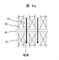
- FIGS. 6a and 6b show magnetic flux paths in a double-sided linear induction motor.
- the wedge-shaped member closing the slot opening is a non-magnetic wedge 51 made of a non-magnetic material.
- the wedge-shaped member is the magnetic wedge 31 in the present embodiment.
- the magnetic flux is applied to one of the two teeth 12 facing each other across the gap, the secondary conductor belt 41 in the gap, and the two opposite faces 12 across the gap. It flows along a path passing through the other of the two teeth 12. Since there is no magnetic flux path through the non-magnetic wedge 51, the magnetic flux concentrates on the aforementioned path. For this reason, slot ripple of magnetic flux occurs, and the efficiency of the linear induction motor decreases.
- the wedge-shaped member is the magnetic wedge 31
- a part of the magnetic flux is added to one of the two teeth 12 opposed to each other with a gap in addition to the same path as in FIG.
- the gap length can be reduced to compensate for a decrease in efficiency due to the reduction in width without increasing loss.
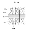
- FIGS. 7a and 7b show the paths of magnetic flux when (pole pitch / gap length) is reduced.
- the wedge-shaped member closing the slot opening is a non-magnetic wedge 51 made of a non-magnetic material.
- the wedge-shaped member is the magnetic wedge 31 in the present embodiment.
- the pole pitch (“ ⁇ ” in FIG. 4) relates to the number of magnetic poles, and thus to the speed of the moving magnetic field. That is, the pole pitch is a parameter related to the speed performance of the linear induction motor. Since the pole pitch relates to the configuration of the three-phase winding applied to the primary core, it also affects the slot width and the width of the teeth of the primary core. For example, in one configuration of the three-phase winding in the primary core having a predetermined length, the interval between two adjacent teeth 12 becomes narrow. The magnetic resistance between the teeth 12 sandwiching the wedge-shaped member is reduced.
- the gap length (“G t ” in FIG. 5) is related to the magnetic resistance between the two teeth 12 facing each other with the gap therebetween. Therefore, (pole pitch / gap length) corresponds to the ratio of the magnetoresistance between adjacent teeth and the magnetoresistance between opposing teeth.
- the wedge-shaped member is the magnetic wedge 31
- the degree of reduction in the magnetic resistance between adjacent teeth is smaller than the degree of reduction in the magnetic resistance between opposing teeth.
- FIG. 7B a path of the magnetic flux via the magnetic wedge 31 is generated between adjacent teeth. Since the magnetic flux flowing through this path does not pass through the secondary conductor belt 41, it does not contribute to the thrust of the linear induction motor. Therefore, when such an amount of magnetic flux increases, the improvement of the efficiency of the linear induction motor is limited even if the magnetic wedge is provided.
- the magnetic wedge is provided on the primary core of the two-sided linear induction motor
- FIG. 8 shows a magnetic flux path in a single-sided linear induction motor.
- the wedge-shaped member is a non-magnetic wedge 51.
- the magnetic wedge is effective in the double-sided linear induction motor as in the present embodiment.
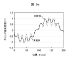
- FIG. 9A shows a magnetic flux distribution (solid line in the figure) in an example to which the magnetic wedge according to the present embodiment is applied.
- the vertical axis represents the gap magnetic flux density in the gap between the pair of primary cores, and the horizontal axis represents the position along the longitudinal direction of the linear induction motor.
- a broken line shows a magnetic flux distribution when the magnetic wedge in the example is replaced with a non-magnetic wedge.
- the use of a magnetic wedge reduces the spatial variation of the magnetic flux density, that is, the slot ripple of the magnetic flux.
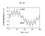
- FIG. 9B shows the distribution of the induced current flowing through the secondary conductor belt (solid line in the figure) in one example to which the magnetic wedge is applied in the present embodiment.
- the vertical axis represents the secondary conductor current density
- the horizontal axis represents the position along the longitudinal direction of the linear induction motor.
- a broken line shows a current distribution when the magnetic wedge in the example is replaced with a non-magnetic wedge.
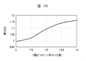
- FIG. 10 shows the relationship between the ratio between the thrust when the magnetic wedge is applied and the thrust when the magnetic wedge is not applied and (pole pitch / gap length).
- the vertical axis represents the thrust ratio
- the horizontal axis represents (pole pitch / gap length).
- the thrust ratio is (thrust when the magnetic wedge is applied / thrust when the magnetic wedge is not applied).
- the case where the magnetic wedge is not applied may be the case where the non-magnetic wedge is used or the case where the wedge-shaped member is not used, that is, the case where the slot opening is opened without being closed.
- FIG. 11 shows the relationship between the ratio of the thrust when the magnetic wedge is applied and the thrust when the magnetic wedge is not applied, and (slot width / slot pitch).
- the slot width and slot pitch are respectively w s and ⁇ s shown in FIG. 11, the vertical axis represents the thrust ratio as in FIG. 10, and the horizontal axis represents (slot width / slot pitch).
- slot width / slot pitch can be one index indicating the design balance between the size of the primary core (the length dimension in the present embodiment) and the thrust.
- (slot width / slot pitch) is preferably 0.5, but can be appropriately set in the range shown in the figure according to the desired size and thrust of the primary core.
- the thrust ratio changes depending on (slot width / slot pitch). In the range (slot width / slot pitch) shown in the figure, the thrust ratio is larger than 1, and the efficiency can be surely improved.
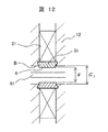
- FIGS. 12 to 17 show modified examples of the magnetic wedge.
- Each drawing is a partial sectional view of the linear induction motor.
- the configuration of the linear induction motor other than the magnetic wedge is the same as in the above-described embodiment (FIG. 3).
- the magnetic wedge 31 has a portion projecting from the primary core into the gap between the pair of primary cores. That is, as shown in FIGS. 12 to 14, the distance g between the distal end faces A of the magnetic wedges 31 exposed in the gap is the distance between the opposed teeth 12, that is, the distance between the end faces B of the teeth 12 exposed in the gap, that is, the gap. less than the length G t (g ⁇ G t) .
- the exposed surface of the magnetic wedge 31 shown in FIG. 12 facing the gap is in the width direction of the slot, that is, in the entire width direction of the magnetic wedge 31 in the longitudinal direction of the primary core (hereinafter, simply referred to as “width direction”).
- the teeth 12 protrude into the gap from a plane including the exposed surface. That is, since the entire exposed surface of the magnetic wedge 31 is the distal end surface, the entire exposed surface of the magnetic wedge 31, a relationship of the aforementioned g ⁇ G t.
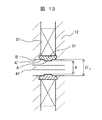
- the exposed surface of the magnetic wedge 31 shown in FIG. 13 toward the gap only the exposed surface A at the center of the center in the width direction of the magnetic wedge 31 and the left and right sides of the center protrudes into the gap. . That is, since the exposed surface of the central portion is the distal end surface A, the exposed surface of the center in the width direction of the magnetic wedge 31, a relationship of the aforementioned g ⁇ G t. Incidentally, the exposed surface A 'the distance between the right and left side portions in the width direction of the magnetic wedge 31 is equal to the gap length G t.
- g ⁇ g ' ⁇ so that the G t, g' may be set.
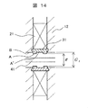
- the exposed surface of the magnetic wedge 31 shown in FIG. 14 facing the gap is such that only the exposed surfaces A on the left and right sides of the central portion in the width direction of the magnetic wedge 31 and the left and right sides of the central portion project into the gap. I do. That is, since the exposed surface of the left and right sides is the distal end surface A, the exposed surface of the right and left side portions in the width direction of the magnetic wedge 31, a relationship of the aforementioned g ⁇ G t. Incidentally, the exposed surface A 'the distance between the center in the width direction of the magnetic wedge 31 is equal to the gap length G t.
- g ⁇ g ' ⁇ so that the G t, g' may be set.
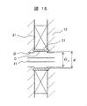
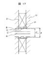
- FIGS. 15 to 17 at least a part of the surface of the magnetic wedge 31 exposed toward the gap is located in the slot. That is, as shown in FIGS. 15-17, the distance g between the surface C located in the slot, the distance between the end surfaces B of the teeth 12 exposed in the gap, i.e. greater than the gap length G t (g> G t ).
- the exposed surface facing the gap of the magnetic wedge 31 shown in FIG. 15 is located in the slot over the entire width of the magnetic wedge 31. That is, the above-described relationship of g> Gt holds for the entire exposed surface of the magnetic wedge 31.
- the exposed surface facing the gap of the magnetic wedge 31 shown in FIG. 16 has only the central exposed surface C of the central portion in the width direction of the magnetic wedge 31 and the right and left sides of the central portion located in the slot. . That is, for the exposed surface of the center in the width direction of the magnetic wedge 31, a relationship of the aforementioned g> G t. Incidentally, the exposed surface C 'the distance between the right and left side portions in the width direction of the magnetic wedge 31 is equal to the gap length G t.
- a g ' G t.
- the present invention is not limited to this, 'so that the> G t, g'g> g may be set.
- the exposed surface facing the gap of the magnetic wedge 31 shown in FIG. 17 is such that only the exposed surfaces A on the left and right sides of the central portion in the width direction of the magnetic wedge 31 and the left and right sides of the central portion are located in the slot. I do. That is, for the exposed surface of the right and left side portions in the width direction of the magnetic wedge 31, a relationship of the aforementioned g> G t. Incidentally, the exposed surface C 'the distance between the center in the width direction of the magnetic wedge 31 is equal to the gap length G t.
- a g ' G t.
- the present invention is not limited to this, 'so that the> G t, g'g> g may be set.
- the magnetic wedges of the modified examples of FIGS. 12 to 17 can also spread the magnetic flux from the teeth 12 to the adjacent slots in the lateral direction, similarly to the above-described embodiment. Therefore, the slot ripple of the magnetic flux is reduced, and the efficiency of the linear induction motor is improved.
- the magnetic flux can be surely spread laterally from the teeth 12 to the adjacent slots. Further, according to the magnetic wedges of the modified examples shown in FIGS. 15 to 17, the gap length Gt can be easily set without considering the structure of the magnetic wedges.
- the magnetic wedges of the present embodiment and FIGS. 12 to 17 can be appropriately selected and used.
- the present invention is not limited to the modified examples of FIGS. 12 to 17, but may be modified such that a part of the surface of the magnetic wedge 31 exposed toward the gap projects into the gap and another part is located in the slot. It is possible.
- the slot ripple of the magnetic flux in the gap between the pair of primary cores of the two-sided linear induction motor is reduced, and the harmonic current generated in the secondary conductor belt is reduced. Can be reduced.
- the efficiency of the double-sided linear induction motor can be improved.
- the width of the double-sided linear induction motor can be reduced without lowering the efficiency.
- an elevator driven by a double-sided linear induction motor can be space-saving and highly efficient.
- the present invention is not limited to the embodiments described above, but includes various modifications.
- the above-described embodiments have been described in detail for easy understanding of the present invention, and are not necessarily limited to those having all of the described configurations. Further, for a part of the configuration of each embodiment, it is possible to add, delete, or replace another configuration.
- the configuration of the elevator is not limited to the configuration of FIG. 1, and a configuration in which the car and the counterweight are suspended in a sling manner by the rope and the secondary conductor belt may be used.
- a simple guide means may be provided outside the pair of primary cores, adjacent to the longitudinal ends of the primary core.
- a part of the tooth may be extended in the slot width direction to cover the opening of the slot.
- the slot it is preferable that the slot be a so-called semi-closed type.
- the protrusion of the magnetic wedge 31 shown in FIGS. 12 to 14 into the gap may be replaced with a non-magnetic material to serve as a guide means for stabilizing the position of the secondary conductor belt in the gap.
- SYMBOLS 1 Linear induction motor, 11 ... Primary side core, 12 ... Teeth, 13 ... Slot, 21, 22, 23 ... Coil, 31 ... Magnetic wedge, 41 ... Secondary conductor belt, 51 ... Non-magnetic wedge, 52 ... Magnetic body Plate, 101a, 101b: Upper pulley, 102a, 102b: Lower pulley, 103a, 103b: Wire rope, 104a, 104b: Car, 105a, 105b: Connection, 201: Inverter, 202: Control device, 203: Rotary encoder , 204 ... current sensor
Abstract
小型化しながらも効率を向上できるリニア誘導モータ並びにそれを用いるエレベーターを開示する。リニア誘導モータは、一対の一次側コア(11)と、一対の一次側コア(11)の間の間隙の内を通るベルト状の二次導体(41)と、を備えるものであって、一次側コア(11)は、複数のティース部(12)と、複数のティース部(12)に隣接し、巻線(21)が設けられる複数のスロット(13)と、を備え、スロット(13)の開口部は、磁性体(31)によって覆われている。
Description
本発明は、リニア誘導モータ並びにそれを用いるエレベーターに関する。
リニア誘導モータによって駆動される従来のエレベーターとして、特許文献1に記載のエレベーター装置が知られている。このエレベーター装置においては、二次導体である平板状のロープが両側式のリニア誘導モータによって駆動される。これにより、ロープによって吊られる乗りかごおよびカウンタウェートが、昇降路内を上下方向に移動する。
上記従来のエレベーターにおいては、ロープに沿う狭い空間にリニア誘導モータを設置するため、リニア誘導モータに対して狭幅化などの小型化が要求される。しかし、リニア誘導モータを小型化すると、効率が低下する。そこで、ギャップ長を低減して効率の低下を抑えようとすると、磁束のスロットリプルにより発生する二次電流の高調波により損失が増加するため、効率の向上が制限される。
そこで、本発明は、小型化しながらも効率を向上できるリニア誘導モータ並びにそれを用いるエレベーターを提供する。
上記課題を解決するために、本発明によるリニア誘導モータは、一対の一次側コアと、一対の一次側コアの間の間隙の内を通るベルト状の二次導体と、を備えるものであって、一次側コアは、複数のティース部と、複数のティース部に隣接し、巻線が設けられる複数のスロットと、を備え、スロットの開口部は、磁性体によって覆われている。
また、上記課題を解決するために、本発明によるエレベーターは、リニア誘導モータによって乗りかごが昇降駆動されるものであって、リニア誘導モータは、上記本発明によるリニア誘導モータであり、乗りかごは、二次導体によって昇降路内において吊られる。
本発明によれば、リニア誘導モータおよびそれを用いるエレベーターの効率が向上する。
上記した以外の課題、構成および効果は、以下の実施形態の説明により明らかにされる。
以下、本発明の実施形態について、図面を用いながら説明する。なお、各図において、参照番号が同一のものは同一の構成要件あるいは類似の機能を備えた構成要件を示している。
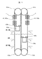
図1は、本発明の一実施形態であるエレベーターの概略構成図である。
本実施形態では、一つの昇降路内において、二台の乗りかご(104a,104b)が、最上階と最下階の間を、互いに上下反対方向へ移動する。
図1に示すように、上部プーリ101aおよび下部プーリ102aに、無端状のワイヤロープ103aおよびベルト状の二次導体ベルト(以下、「二次導体ベルト41」と記す)が巻き掛けられる。なお、図1では、ワイヤロープ103aおよび二次導体ベルト41が重ねて描かれている(ワイヤロープ103bおよび二次導体ベルト41についても同様)。また、上部プーリ101bおよび下部プーリ102bに、無端状のワイヤロープ103bおよび二次導体ベルト41が巻き掛けられる。なお、ワイヤロープ103a,103bおよび二次導体ベルト41は樹脂で被覆されていてもよい。
上部プーリ101aおよび下部プーリ102aに巻き掛けられるワイヤロープ103aおよび二次導体ベルト41の一部と、この一部と同方向に駆動される、上部プーリ101bおよび下部プーリ102bに巻き掛けられるワイヤロープ103bおよび二次導体ベルト41の一部とが、それぞれ、乗りかご104aに設けられる一対の連結部105aの一方および他方に取り付けられる。また、上部プーリ101aおよび下部プーリ102aに巻き掛けられるワイヤロープ103aおよび二次導体41の他の一部と、この他の一部と同方向に駆動される、上部プーリ101bおよび下部プーリ102bに巻き掛けられるワイヤロープ103bおよび二次導体ベルト41の他の一部とが、それぞれ、乗りかご104bに設けられる一対の連結部105bの一方および他方に取り付けられる。これにより、乗りかご104a,104bは、図示されない昇降路内において二次導体ベルト41およびワイヤロープ103a,103bによって吊られる。また、二次導体ベルト41およびワイヤロープ103a,103bが駆動されると、乗りかご(104a,104b)が、一つの昇降路内において、互いに上下反対方向へ移動する。
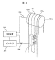
図2は、図1のエレベーターにおける上部プーリの付近の構成を示す。なお、図1における上部プーリ101a,101bの内、上部プーリ101aのみを示す。なお、上部プーリ101bの付近の構成は、本図2に示す上部プーリ101aの付近の構成と同様である。
図2に示すように、上部プーリ101aには、複数(図2では2本)のワイヤロープ103aが巻き掛けられるとともに、2本のワイヤロープ103aの間に二次導体ベルト41が巻き掛けられる。ワイヤロープ103aは、鋼線からなる公知のエレベーター用ロープである。二次導体ベルト41は、平板状かつベルト状の非磁性導体から構成される。
本実施形態におけるリニア誘導モータ1は、両側式であり、三相巻線が施される一対の一次側コアを備える。一対の一次側コアは、所定の間隙を介して対向し、一次側コアの長手方向が、二次導体ベルト41が上下に伸びる方向に沿うように、昇降路内に固定的に取り付けられる。二次導体ベルト41は、一対の一次側コアの長手方向における上下端部間における、これら一次側コア間の間隙を通る。なお、本実施形態において、リニア誘導モータ1の一次側コアは、最上階(図1)よりも上方において乗りかごが到達しない空間に取り付けられる。
リニア誘導モータ1の三相巻線には、インバータ201によって、可変周波数および可変電圧の三相交流電力が供給される。これにより、二次導体ベルト41が駆動されて、乗りかごが駆動される。また、制御装置202は、上部プーリ101aに回転可能に接続され上部プーリ101aの回転を検出するロータリエンコーダの信号と、インバータ201から三相巻線への出力電流を検出する電流センサの信号とに基づいて、インバータ201を制御する。これにより、乗りかごの速度が制御される。
後述するように、本実施形態におけるリニア誘導モータ1によれば、一次側コアの長手方向に直角な幅寸法を狭くすることができる。このため、図2に示すように、昇降路内でかつ2本のワイヤロープ103a間という狭隘な空間に、リニア誘導モータ1を設置することができる。
図3は、本発明の一実施形態であるリニア誘導モータの構成を示す断面図である。なお、本図は、図1および図2に示されるエレベーターが備えるリニア誘導モータ1の長手方向(図3中のx方向)に沿った断面を示す。
図3に示すように、リニア誘導モータ1は、所定の間隙を介して対向する一対の一次側コア11と、これら一次側コア間の間隙内に位置する二次導体ベルト41を備える。すなわち、本実施形態は、いわゆる両側式のリニア誘導モータである。両側式のリニア誘導モータは、二次導体に作用するが推力には寄与しない垂直力を低減できるので、図1のエレベーターのように直線状に伸びる二次導体を駆動する場合には好適である。
一次側コア11は、複数のティース12を備え、図3に示すように櫛歯状の長手方向断面を有する。一対の一次側コア11は、二次導体ベルト41の直線状部分を対称軸として、二次導体ベルト41の両側に線対称に配置される。従って、一方の一次側コア11における各ティース12の先端部の露出端面と、他方の一次側コア11における各ティース12の先端部の露出端面とが、互いにオーバーラップするように、対向する。
一次側コア11には、三相巻線が施される。三相巻線は、一次側コア11の両端部付近に巻かれるコイル22,23、一次側コア11の中央部を含む主要部(二次導体ベルト41に推力を与える部分)に巻かれるコイル21から構成される。コイル21,22,23を構成する導線は、隣り合う2個のティース12間の空間すなわちスロット13内を通るとともに、一次側コア11の幅方向(図中のy方向)外側を通る。コイル21,22,23すなわち三相巻線における一次側コア11の幅方向外側に位置する部分は、図示されないコイルエンドを構成する。
隣り合う二個のティース12間には、スロット13の二次導体ベルト41側の開口部を覆う磁性体である磁性楔31が設けられる。本実施形態では、スロット13の開口部が、磁性楔31によって閉塞され、いわば全閉状態にある。これにより、コイル21,22,23がスロット13内に固定されるとともに、後述するように、磁束のスロットリプルを抑制してリニア誘導モータ1の効率を向上することができる。
一次側コア11は磁性体から構成される。好ましくは、一次側コア11は、平面形状が図3に示すような櫛歯形状である電磁鋼板の積層体によって構成される。これにより、鉄損(渦電流損)を低減できる。
本実施形態では、1スロット内において、コイル22,23の巻数をコイル21の巻数よりも少なくしている(図3では、コイル21の巻数の1/2)。これにより、いわゆる端効果、すなわち一次側コア11の両端部における磁束分布の急激な変化に伴う推力の低下が抑制される。
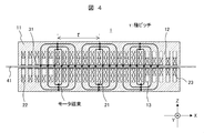
図4は、図3のリニア誘導モータにおける、主たる磁束の流れを示す。なお、図4は、三相巻線に三相交流が流れる場合の、ある一時点における磁束の流れを示す
本実施形態では、図4に示すように、一対の一次側コア11間の間隙に、磁極数3個で極ピッチがτの磁界が発生する。モータ磁束は、各一次側コア11のティース12と一次側コア11間の間隙と二次導体ベルト41を通って、各磁極の周りを循環するように流れる。これらの磁極は、三相交流電流の周波数および磁極数に応じた速さで、一次側コア11の長手方向(図4中のx方向)に沿って移動する。これにより、二次導体ベルト41に誘導電流が流れ、この誘導電流と、二次導体ベルト41を通る磁束とによって、二次導体ベルト41に推力が発生する。
本実施形態では、図4に示すように、一対の一次側コア11間の間隙に、磁極数3個で極ピッチがτの磁界が発生する。モータ磁束は、各一次側コア11のティース12と一次側コア11間の間隙と二次導体ベルト41を通って、各磁極の周りを循環するように流れる。これらの磁極は、三相交流電流の周波数および磁極数に応じた速さで、一次側コア11の長手方向(図4中のx方向)に沿って移動する。これにより、二次導体ベルト41に誘導電流が流れ、この誘導電流と、二次導体ベルト41を通る磁束とによって、二次導体ベルト41に推力が発生する。
なお、磁極数および極ピッチは、リニア誘導モータの構成や所望の特性に応じて、三相巻線の構成によって適宜設定できる。
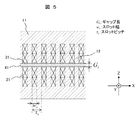
図5は、図3のリニア誘導モータの部分断面図である。
図5に示すように、一次側コア11においては、一次側コア11の長手方向に沿った所定のスロット幅wsのスロット(コイル21が格納される空間)が、所定のスロットピッチτsで複数配置される。ここで、スロットピッチτsは、隣り合う2個のスロットの間隔であり、本実施形態では、ティース12の一次側コア11の長手方向に沿った幅を一定にしているので、スロット幅wsとティースの幅との和となる。また、二次導体ベルト41は、一対の一次側コア11間における所定のギャップ長Gtの間隙を通る。ここで、ギャップ長Gtは、対向するティース12間、すなわち間隙において露出するティース12の端面間の距離である。
磁性楔31は、楔状の磁性体であり、スロットの開口部に嵌めこまれ、スロットの開口を塞ぐ。本実施形態では、一対の一次側コア11間の間隙において露出する磁性楔31の端面は、間隙において露出するティース12の端面と、実質同一の平面内に位置する。すなわち、一対の一次側コア11の対向面は、凹凸が殆どなく、実質平坦面である。従って、本実施形態では、対向する磁性楔31間、すなわち間隙において露出する磁性楔31の端面間の距離は、実質、ギャップ長Gtに等しい。なお、本実施形態では、磁性楔31の端面間の距離が、スロット幅の方向における磁性楔31の略全領域においてギャップ長Gtに等しいので、磁性楔31の構成が、ギャップ長Gtの設定にほとんど影響しない。
磁性楔31を構成する磁性体の比透磁率は、一次側コア11を構成する磁性体(例えば、珪素鋼板などの電磁鋼板)の比透磁率よりも小さくすることが好ましく、例えば1~2桁の値(μs(比透磁率):1<μs<100)とする。これにより、磁束のスロットリプルを確実に抑制できる。なお、磁性楔31を構成する磁性体として、例えば、鉄粉のような強磁性体の粉末とガラス樹脂のような樹脂との混合体や、強磁性体と非磁性体の混合体が適用できる。これにより、磁性楔の比透磁率を適宜調整することができる。
なお、本発明者の検討によれば、磁性楔31による磁束のスロットリプルの抑制効果は、後述するように、図4に示す極ピッチτ、図5に示すギャップ長Gtおよびスロット幅ws並びにスロットピッチτsによって変化する。
以下、磁性楔の作用効果に関する本発明者の検討結果について、図6a~11を用いて説明する。
図6aおよび図6bは、両側式リニア誘導モータにおける磁束経路を示す。図6aにおいては、スロット開口を塞ぐ楔状部材が、非磁性体からなる非磁性楔51である。また、図6bにおいては、楔状部材が、本実施形態における磁性楔31である。
図6aに示すように、楔状部材が非磁性楔51である場合、磁束は、間隙を挟んで対向する2つのティース12の一方、間隙中の二次導体ベルト41、間隙を挟んで対向する2つのティース12の他方を通る経路で流れる。非磁性楔51を通る磁束経路は生じないので、磁束は、前述の経路に集中する。このため、磁束のスロットリプルが発生して、リニア誘導モータの効率が低下する。
これに対し、図6bに示すように、楔状部材が磁性楔31である場合、磁束の一部は、図6aと同様の経路に加えて、間隙を挟んで対向する2つのティース12の一方、この一方のティースに隣接する磁性楔31、間隙中の二次導体ベルト41、間隙を挟んで対向する2つのティース12の他方に隣接する磁性楔31、この他方のティース12を通る経路で流れる。このため、間隙中の磁束が、対向する2つのティース12間における集中が緩和され、ティース12から隣接するスロットに向って横方向に広がる。このため、磁束のスロットリプルが低減され、リニア誘導モータの効率が向上する。また、リニア誘導モータを幅狭化する場合、ギャップ長を短くして、損失を増大することなく幅狭化による効率の低下を補償することができる。
図7aおよび図7bは、(極ピッチ/ギャップ長)を小さくした場合における磁束の経路を示す。図7aにおいては、スロット開口を塞ぐ楔状部材が、非磁性体からなる非磁性楔51である。また、図7bにおいては、楔状部材が、本実施形態における磁性楔31である。
ここで、極ピッチ(図4の「τ」)は、磁極数に関わり、従って移動磁界の速度に関わる。すなわち、極ピッチはリニア誘導モータの速度性能に関わるパラメータである。極ピッチは、一次側コアに施される三相巻線の構成に関わるので、一次側コアのスロット幅やティースの幅にも関わる。例えば、所定の長さの一次側コアにおける三相巻線の一構成では、隣り合う二つのティース12の間隔が狭くなる。楔状部材を挟んだティース12間の磁気抵抗は低減する。また、ギャップ長(図5の「Gt」)は、間隙を挟んで対向する二つのティース12間の磁気抵抗に関係する。従って、(極ピッチ/ギャップ長)は、隣り合うティース間の磁気抵抗と対向するティース間の磁気抵抗の比に対応する。
図7aに示すように、楔状部材が非磁性楔51である場合、(極ピッチ/ギャップ長)を低減しても、磁束は、図6aと同様に、間隙を挟んで対向する2つのティース12の一方、間隙中の二次導体ベルト41、間隙を挟んで対向する2つのティース12の他方を通る経路に集中して流れる。
これに対し、楔状部材が磁性楔31である場合、(極ピッチ/ギャップ長)を低減すると、隣り合うティース間の磁気抵抗の低減の度合いが対向するティース間の磁気抵抗の低減の度合いよりも大きくなるので、図7bに示すように、隣り合うティース間に磁性楔31を経由する磁束の経路が生じる。この経路を流れる磁束は、二次導体ベルト41を通らないので、リニア誘導モータの推力に寄与しない。従って、このような磁束量が増えると、磁性楔を設けても、リニア誘導モータの効率向上が制限される。
このように、本発明者の検討によれば、両側式のリニア誘導モータの一次側コアに磁性楔を設ける本実施形態では、磁性楔を設けて確実にリニア誘導モータの効率を向上するには、一次側コアの構成について考慮を要する。
図8は、片側式のリニア誘導モータにおける磁束経路を示す。なお、楔状部材は非磁性楔51である。
図8に示すように、二次導体ベルト41に磁性体板52が裏打ちされているため、磁束は、ティース12と二次導体ベルト41の間隙において、ティース12から隣接するスロットに向って横方向に広がる。従って、片側式のリニア誘導モータでは、磁束のスロットリプルは生じ難い。また、図中の非磁性楔51を磁性楔に替えた場合、前述の図7bのように、磁性楔を介して隣り合うティース12間に推力に寄与しない磁束が流れてしまう。
このように、本発明者の検討によれば、磁性楔は、本実施形態のような両側式のリニア誘導モータにおいて有効である。
図9aは、本実施形態における磁性楔を適用する一実施例における磁束分布(図中の実線)を示す。縦軸は、一対の一次側コア間の間隙におけるギャップ磁束密度を表し、横軸は、リニア誘導モータの長手方向に沿った位置を表す。なお、比較例として、実施例における磁性楔を非磁性楔に替えた場合の磁束分布を破線で示す。
図9aに示すように、磁性楔を用いると、磁束密度の空間的変動、すなわち磁束のスロットリプルが低減される。
図9bは、本実施形態における磁性楔を適用する一実施例における二次導体ベルトに流れる誘導電流の分布(図中の実線)を示す。縦軸は、二次導体電流密度を表し、横軸は、リニア誘導モータの長手方向に沿った位置を表す。なお、比較例として、実施例における磁性楔を非磁性楔に替えた場合の電流分布を破線で示す。
図9bに示すように、磁性楔を用いると、図9aに示す磁束のスロットリプルの低減に応じて、二次導体ベルトに流れる誘導電流の空間高調波が低減する。これにより、二次導体ベルトに発生する損失が低減される。
図10は、磁性楔を適用した場合の推力と磁性楔を適用しない場合の推力の比と、(極ピッチ/ギャップ長)との関係を示す。縦軸は、推力比を表し、横軸は、(極ピッチ/ギャップ長)を表す。ここで、推力比は、(磁性楔を適用した場合の推力/磁性楔を適用しない場合の推力)である。なお、磁性楔を適用しない場合とは、非磁性楔を用いる場合のほか、楔状部材を用いない場合、すなわちスロット開口部が塞がれずに開放されている場合でも良い。
上述のように(図7a)、磁性楔を設けて確実にリニア誘導モータの効率を向上するには、一次側コアの構成について考慮を要する。一次側コアの構成を表す一つのパラメータである(極ピッチ/ギャップ長)については、図10に示すように、(極ピッチ/ギャップ長)によっては、磁性楔を設けても推力が低下してしまう場合があり得る。本実施形態では、図10においては、(極ピッチ/ギャップ長)が6よりも小さくなると、推力比が1よりも小さくなる。従って、(極ピッチ/ギャップ長)は6よりも大きくすることにより、確実に効率を向上することができる。なお、本発明者の検討によれば、より実効的に効率を向上するためには、(極ピッチ/ギャップ長)を10よりも大きくすることが好ましい。
図11は、磁性楔を適用した場合の推力と磁性楔を適用しない場合の推力の比と、(スロット幅/スロットピッチ)との関係を示す。スロット幅およびスロットピッチは、それぞれ、図5に示すwsおよびτsである。図11において、縦軸は、図10と同様に推力比を表し、横軸は、(スロット幅/スロットピッチ)を表す。
本発明者の検討によれば、(スロット幅/スロットピッチ)は、一次側コアのサイズ(本実施形態では長さ寸法)と推力の設計的バランスを表す一つの指標となり得る。本発明者の検討によれば、(スロット幅/スロットピッチ)としては0.5が好ましいが、所望の一次側コアのサイズおよび推力に応じて、図示の範囲において適宜設定できる。
図11に示すように、推力比は(スロット幅/スロットピッチ)によって変化する。図示す範囲の(スロット幅/スロットピッチ)では、推力比は1よりも大きく、確実に効率を向上できる。
図12~17は、磁性楔の変形例を示す。各図は、リニア誘導モータの部分断面図である。なお、各図において、磁性楔以外のリニア誘導モータの構成は、上述の実施形態(図3)と同様である。
図12~14において、磁性楔31は、一次側コアから、一対の一次側コア間の間隙内へ突出する部分を有する。すなわち、図12~14に示すように、間隙に露出する磁性楔31の先端面A間の距離gは、対向するティース12間、すなわち間隙において露出するティース12の端面B間の距離、すなわちギャップ長Gtよりも小さい(g<Gt)。
図12に示す磁性楔31の、間隙に向かう露出面は、スロット幅の方向、すなわち一次側コアの長手方向における磁性楔31の幅方向(以下、単に「幅方向」と記す)の全体において、ティース12の露出面を含む平面から間隙内へ突出する。すなわち、磁性楔31の露出面全体が先端面であるため、磁性楔31の露出面全体について、上述のg<Gtの関係がある。
図13に示す磁性楔31の、間隙に向かう露出面は、磁性楔31の幅方向における中央部と、中央部の左右両側部との内、中央部の露出面Aのみが間隙内へ突出する。すなわち、中央部の露出面が先端面Aであるため、磁性楔31の幅方向の中央部の露出面については、上述のg<Gtの関係がある。なお、磁性楔31の幅方向の左右両側部の露出面A’間の距離は、ギャップ長Gtに等しい。
磁性楔31の幅方向の左右両側部の露出面A’間の距離をg’とすれば、図13の変形例では、g’=Gtである。これに限らず、g<g’<Gtとなるように、g’を設定しても良い。
図14に示す磁性楔31の、間隙に向かう露出面は、磁性楔31の幅方向における中央部と、中央部の左右両側部との内、左右両側部の露出面Aのみが間隙内へ突出する。すなわち、左右両側の露出面が先端面Aであるため、磁性楔31の幅方向の左右両側部の露出面については、上述のg<Gtの関係がある。なお、磁性楔31の幅方向の中央部の露出面A’間の距離は、ギャップ長Gtに等しい。
磁性楔31の幅方向の中央部の露出面A’間の距離をg’とすれば、図14の変形例では、g’=Gtである。これに限らず、g<g’<Gtとなるように、g’を設定しても良い。
図15~17において、磁性楔31は、間隙に向って露出する磁性楔31の表面のすくなとも一部がスロット内に位置する。すなわち、図15~17に示すように、スロット内に位置する表面C間の距離gは、間隙において露出するティース12の端面B間の距離、すなわちギャップ長Gtよりも大きい(g>Gt)。
図15に示す磁性楔31の間隙に向かう露出面は、磁性楔31の幅方向の全体において、スロット内に位置する。すなわち、磁性楔31の露出面全体について、上述のg>Gtの関係がある。
図16に示す磁性楔31の間隙内に向かう露出面は、磁性楔31の幅方向における中央部と、中央部の左右両側部との内、中央部の露出面Cのみがスロット内に位置する。すなわち、磁性楔31の幅方向の中央部の露出面については、上述のg>Gtの関係がある。なお、磁性楔31の幅方向の左右両側部の露出面C’間の距離は、ギャップ長Gtに等しい。
磁性楔31の幅方向の左右両側部の露出面C’間の距離をg’とすれば、図16の変形例では、g’=Gtである。これに限らず、g>g’>Gtとなるように、g’を設定しても良い。
図17に示す磁性楔31の間隙内に向かう露出面は、磁性楔31の幅方向における中央部と、中央部の左右両側部との内、左右両側部の露出面Aのみがスロット内に位置する。すなわち、磁性楔31の幅方向の左右両側部の露出面については、上述のg>Gtの関係がある。なお、磁性楔31の幅方向の中央部の露出面C’間の距離は、ギャップ長Gtに等しい。
磁性楔31の幅方向の中央部の露出面C’間の距離をg’とすれば、図17の変形例では、g’=Gtである。これに限らず、g>g’>Gtとなるように、g’を設定しても良い。
図12~17の変形例の磁性楔によっても、上述の実施形態と同様に、磁束をティース12から隣接するスロットに向って横方向に広げることができる。このため、磁束のスロットリプルが低減され、リニア誘導モータの効率が向上する。
さらに、図12~14の変形例の磁性楔によれば、磁束をティース12から隣接するスロットに向って横方向に確実に広げることができる。また、図15~17の変形例の磁性楔によれば、磁性楔の構造を考慮せずに、ギャップ長Gtを容易に設定することができる。
一次側コアや二次導体ベルトの構成、所望のリニア誘導モータの性能に応じて磁束分布を調整するために、本実施形態および図12~17の磁性楔を適宜選択して用いることができる。
なお、図12~17の変形例に限らず、間隙に向って露出する磁性楔31の表面の一部が間隙内に突出するとともに、他の一部がスロット内に位置するような変形例も可能である。
上述のように、本実施形態並びにその変形例によれば、両側式のリニア誘導モータの一対の一次側コアの間隙における磁束のスロットリプルが低減され、二次導体ベルトに発生する高調波電流を低減できる。これにより、両側式のリニア誘導モータの効率を向上することができる。また、本実施形態並びにその変形例によれば、効率を低下することなく、両側式のリニア誘導モータを幅狭化にすることができる。また、両側式のリニア誘導モータによって駆動されるエレベーターを省スペース化および高効率化することができる。
なお、本発明は前述した実施例に限定されるものではなく、様々な変形例が含まれる。例えば、前述した実施例は本発明を分かりやすく説明するために詳細に説明したものであり、必ずしも説明した全ての構成を備えるものに限定されるものではない。また、各実施例の構成の一部について、他の構成の追加・削除・置き換えをすることが可能である。
例えば、エレベーターの構成は、図1の構成に限らず、乗りかごとつり合いおもりがロープおよび二次導体ベルトによってつるべ式に吊られる構成でもよい。
また、一対の一次側コアの外部において、一次側コアの長手方向の両端部に隣接して、二次導体ベルトを、一対の一次側コア間の間隙内へ案内するために、ガイドローラのような案内手段を設けてもよい。
また、磁性楔に替えて、ティースの一部をスロット幅方向へ延ばして、スロットの開口部を覆ってもよい。この場合、スロットをいわゆる半閉型にすることが好ましい。
また、図12~14に示す磁性楔31における間隙内への突出部を非磁性体に替えることにより、間隙内における二次導体ベルトの位置を安定化するための案内手段としてもよい。
1…リニア誘導モータ、11…一次側コア、12…ティース、13…スロット、21,22,23…コイル、31…磁性楔、41…二次導体ベルト、51…非磁性楔、52…磁性体板、101a,101b…上部プーリ、102a,102b…下部プーリ、103a,103b…ワイヤロープ、104a,104b…乗りかご、105a,105b…連結部、201…インバータ、202…制御装置、203…ロータリエンコーダ、204…電流センサ
Claims (13)
- 一対の一次側コアと、
前記一対の一次側コアの間の間隙の内を通るベルト状の二次導体と、
を備えるリニア誘導モータにおいて、
前記一次側コアは、
複数のティース部と、
前記複数のティース部に隣接し、巻線が設けられる複数のスロットと、
を備え、
前記スロットの開口部は、磁性体によって覆われていることを特徴とするリニア誘導モータ。 - 請求項1に記載のリニア誘導モータにおいて、
(極ピッチ/ギャップ長)が6より大であることを特徴とするリニア誘導モータ。 - 請求項1に記載のリニア誘導モータにおいて、
(極ピッチ/ギャップ長)が10より大であることを特徴とするリニア誘導モータ。 - 請求項1に記載のリニア誘導モータにおいて、
(スロット幅/スロットピッチ)が0.5であることを特徴とするリニア誘導モータ。 - 請求項2乃至4のいずれか一項に記載のリニア誘導モータにおいて、
推力が、前記磁性体を非磁性体に替えた場合に比べて、大きくなることを特徴とするリニア誘導モータ。 - 請求項1に記載のリニア誘導モータにおいて、
前記スロットの前記開口部を覆う前記磁性体の透磁率は、前記一次側コアを構成する磁性体の透磁率よりも小さいことを特徴とするリニア誘導モータ。 - 請求項6に記載のリニア誘導モータにおいて、
前記スロットの前記開口部を覆う前記磁性体の比透磁率μsは、1<μs<100であることを特徴とするリニア誘導モータ。 - 請求項7に記載のリニア誘導モータにおいて、
前記一次側コアを構成する前記磁性体が電磁鋼板の積層体であることを特徴とするリニア誘導モータ。 - 請求項1に記載のリニア誘導モータにおいて、
前記一次側コアにおける前記スロットの前記開口部を覆う前記磁性体の前記間隙に向かう露出面の間の距離がギャップ長に等しいことを特徴とするリニア誘導モータ。 - 請求項1に記載のリニア誘導モータにおいて、
前記一次側コアにおける前記前記スロットの前記開口部を覆う前記磁性体の前記間隙に向かう露出面の一部の間の距離がギャップ長よりも小さいことを特徴とするリニア誘導モータ。 - 請求項1に記載のリニア誘導モータにおいて、
前記一次側コアにおける前記前記スロットの前記開口部を覆う前記磁性体の前記間隙に向かう露出面の一部の間の距離がギャップ長よりも大きいことを特徴とするリニア誘導モータ。 - 請求項1に記載のリニア誘導モータにおいて、
前記前記スロットの前記開口部を覆う前記磁性体が磁性楔であることを特徴とするリニア誘導モータ。 - リニア誘導モータによって乗りかごが昇降駆動されるエレベーターにおいて、
前記リニア誘導モータは、
一対の一次側コアと、
前記一対の一次側コアの間の間隙の内を通るベルト状の二次導体と、
を備え、
前記一次側コアは、
複数のティース部と、
前記複数のティース部に隣接し、巻線が設けられる複数のスロットと、
を備え、
前記スロットの開口部は、磁性体によって覆われ、
前記乗りかごは、前記二次導体によって昇降路内において吊られることを特徴とするエレベーター。
Priority Applications (1)
| Application Number | Priority Date | Filing Date | Title |
|---|---|---|---|
| PCT/JP2018/025190 WO2020008521A1 (ja) | 2018-07-03 | 2018-07-03 | リニア誘導モータ並びにエレベーター |
Applications Claiming Priority (1)
| Application Number | Priority Date | Filing Date | Title |
|---|---|---|---|
| PCT/JP2018/025190 WO2020008521A1 (ja) | 2018-07-03 | 2018-07-03 | リニア誘導モータ並びにエレベーター |
Publications (1)
| Publication Number | Publication Date |
|---|---|
| WO2020008521A1 true WO2020008521A1 (ja) | 2020-01-09 |
Family
ID=69060464
Family Applications (1)
| Application Number | Title | Priority Date | Filing Date |
|---|---|---|---|
| PCT/JP2018/025190 WO2020008521A1 (ja) | 2018-07-03 | 2018-07-03 | リニア誘導モータ並びにエレベーター |
Country Status (1)
| Country | Link |
|---|---|
| WO (1) | WO2020008521A1 (ja) |
Cited By (1)
| Publication number | Priority date | Publication date | Assignee | Title |
|---|---|---|---|---|
| WO2023209727A1 (en) * | 2022-04-27 | 2023-11-02 | INDIAN INSTITUTE OF TECHNOLOGY MADRAS (IIT Madras) | "linear induction motor with reduced end-effects" |
Citations (5)
| Publication number | Priority date | Publication date | Assignee | Title |
|---|---|---|---|---|
| JPS58105755U (ja) * | 1982-01-13 | 1983-07-19 | 三菱電機株式会社 | 磁性楔 |
| JPS6277030A (ja) * | 1985-09-27 | 1987-04-09 | Hitachi Ltd | 回転電機の磁性楔 |
| JP2001095225A (ja) * | 1999-09-20 | 2001-04-06 | Yaskawa Electric Corp | リニアモータ |
| JP2005503095A (ja) * | 2001-04-09 | 2005-01-27 | ビーイーアイ・テクノロジーズ・インク | 鉄心複合アーマチャ組立を有するリニア・ブラシレス・dcモータ |
| JP2005239418A (ja) * | 2004-03-01 | 2005-09-08 | Hitachi Ltd | エレベーター装置 |
-
2018
- 2018-07-03 WO PCT/JP2018/025190 patent/WO2020008521A1/ja active Application Filing
Patent Citations (5)
| Publication number | Priority date | Publication date | Assignee | Title |
|---|---|---|---|---|
| JPS58105755U (ja) * | 1982-01-13 | 1983-07-19 | 三菱電機株式会社 | 磁性楔 |
| JPS6277030A (ja) * | 1985-09-27 | 1987-04-09 | Hitachi Ltd | 回転電機の磁性楔 |
| JP2001095225A (ja) * | 1999-09-20 | 2001-04-06 | Yaskawa Electric Corp | リニアモータ |
| JP2005503095A (ja) * | 2001-04-09 | 2005-01-27 | ビーイーアイ・テクノロジーズ・インク | 鉄心複合アーマチャ組立を有するリニア・ブラシレス・dcモータ |
| JP2005239418A (ja) * | 2004-03-01 | 2005-09-08 | Hitachi Ltd | エレベーター装置 |
Cited By (1)
| Publication number | Priority date | Publication date | Assignee | Title |
|---|---|---|---|---|
| WO2023209727A1 (en) * | 2022-04-27 | 2023-11-02 | INDIAN INSTITUTE OF TECHNOLOGY MADRAS (IIT Madras) | "linear induction motor with reduced end-effects" |
Similar Documents
| Publication | Publication Date | Title |
|---|---|---|
| KR950001902B1 (ko) | 리니어모터(linear motor) 엘리베이터 | |
| JPH0439285A (ja) | リニアモータエレベーター | |
| KR102650094B1 (ko) | 스위치형 플럭스 선형 모터를 가진 도어 오퍼레이터 | |
| WO2020008521A1 (ja) | リニア誘導モータ並びにエレベーター | |
| JPH05186165A (ja) | リニアモータ駆動方式エレベータ装置 | |
| JPH05252724A (ja) | エレベータ用リニアモータ | |
| US20110175497A1 (en) | Motor and electronic apparatus using the same | |
| JP4993713B2 (ja) | エレベータの乗籠への給電装置 | |
| JP5089113B2 (ja) | エレベータのかごへの非接触給電装置 | |
| US5174416A (en) | Linear induction motor for elevator | |
| EP0599331B1 (en) | Elevator driven by linear motor | |
| JP2583697B2 (ja) | リニアモータエレベーター | |
| JP5932486B2 (ja) | エレベーター装置 | |
| JPH1198725A (ja) | モータおよびエレベータ | |
| JP2500546B2 (ja) | エレベ―タ装置 | |
| JP4176289B2 (ja) | エレベータ装置 | |
| US789765A (en) | Rope-drive for elevators. | |
| KR0137949Y1 (ko) | 선형 구동 방식 엘리베이터장치 | |
| KR940011705B1 (ko) | 엘리베이터용 리니어유도전동기 | |
| JP2019187164A (ja) | 回転電機、および、エレベーター巻上げシステム | |
| JP4419684B2 (ja) | エレベーター装置 | |
| JPH0439286A (ja) | リニアモータエレベータ | |
| CN109153528B (zh) | 非接触供电装置及使用它的电梯 | |
| JPH09331667A (ja) | リニア誘導モータ | |
| JPH0585683A (ja) | エレベータ用リニアモータ |
Legal Events
| Date | Code | Title | Description |
|---|---|---|---|
| 121 | Ep: the epo has been informed by wipo that ep was designated in this application |
Ref document number: 18925167 Country of ref document: EP Kind code of ref document: A1 |
|
| NENP | Non-entry into the national phase |
Ref country code: DE |
|
| 122 | Ep: pct application non-entry in european phase |
Ref document number: 18925167 Country of ref document: EP Kind code of ref document: A1 |
|
| NENP | Non-entry into the national phase |
Ref country code: JP |