WO2020004204A1 - ロボット、及び制御方法 - Google Patents
ロボット、及び制御方法 Download PDFInfo
- Publication number
- WO2020004204A1 WO2020004204A1 PCT/JP2019/024385 JP2019024385W WO2020004204A1 WO 2020004204 A1 WO2020004204 A1 WO 2020004204A1 JP 2019024385 W JP2019024385 W JP 2019024385W WO 2020004204 A1 WO2020004204 A1 WO 2020004204A1
- Authority
- WO
- WIPO (PCT)
- Prior art keywords
- support
- target
- support target
- robot
- unit
- Prior art date
Links
Images


Classifications
-
- B—PERFORMING OPERATIONS; TRANSPORTING
- B60—VEHICLES IN GENERAL
- B60P—VEHICLES ADAPTED FOR LOAD TRANSPORTATION OR TO TRANSPORT, TO CARRY, OR TO COMPRISE SPECIAL LOADS OR OBJECTS
- B60P1/00—Vehicles predominantly for transporting loads and modified to facilitate loading, consolidating the load, or unloading
- B60P1/02—Vehicles predominantly for transporting loads and modified to facilitate loading, consolidating the load, or unloading with parallel up-and-down movement of load supporting or containing element
- B60P1/025—Vehicles predominantly for transporting loads and modified to facilitate loading, consolidating the load, or unloading with parallel up-and-down movement of load supporting or containing element with a loading platform inside the wheels of a same axle and being lowerable below the axle
-
- B—PERFORMING OPERATIONS; TRANSPORTING
- B25—HAND TOOLS; PORTABLE POWER-DRIVEN TOOLS; MANIPULATORS
- B25J—MANIPULATORS; CHAMBERS PROVIDED WITH MANIPULATION DEVICES
- B25J19/00—Accessories fitted to manipulators, e.g. for monitoring, for viewing; Safety devices combined with or specially adapted for use in connection with manipulators
- B25J19/02—Sensing devices
- B25J19/021—Optical sensing devices
- B25J19/023—Optical sensing devices including video camera means
-
- B—PERFORMING OPERATIONS; TRANSPORTING
- B62—LAND VEHICLES FOR TRAVELLING OTHERWISE THAN ON RAILS
- B62D—MOTOR VEHICLES; TRAILERS
- B62D57/00—Vehicles characterised by having other propulsion or other ground- engaging means than wheels or endless track, alone or in addition to wheels or endless track
- B62D57/02—Vehicles characterised by having other propulsion or other ground- engaging means than wheels or endless track, alone or in addition to wheels or endless track with ground-engaging propulsion means, e.g. walking members
- B62D57/032—Vehicles characterised by having other propulsion or other ground- engaging means than wheels or endless track, alone or in addition to wheels or endless track with ground-engaging propulsion means, e.g. walking members with alternately or sequentially lifted supporting base and legs; with alternately or sequentially lifted feet or skid
Definitions
- the present disclosure relates to a robot and a control method.
- a general luggage transport robot transports luggage by performing a series of operations such as loading luggage on a luggage carrier, moving the luggage to a destination, and unloading luggage from the luggage luggage.
- Loading and unloading of luggage is performed by an arm of the luggage transport robot, an arm device installed outside, or the like.
- the movement to the transport destination is performed by a movement mechanism such as a leg.
- the mechanism of a general luggage transport robot is divided according to the operation. Therefore, in order for the load carrying robot to perform the above-described operation, a space for operating the arm device when loading / unloading the load and a space for moving the load when carrying the load are required.
- the luggage transport robot cannot secure a sufficient working space, it is difficult to transport luggage by the luggage transport robot. Therefore, it is desirable that the luggage transport robot be able to work in a smaller work space by having a simpler configuration and a smaller luggage transport robot.
- Patent Literature 1 discloses a legged mobile robot that performs loading and unloading of goods to and from a trunk by using legs, and moving to a destination by using the legs. ing.
- the legged mobile robot has a simpler configuration than a general luggage transport robot because its legs also serve as an arm mechanism and a moving mechanism.
- the legs of the legged mobile robot are provided outside the legged mobile robot.
- the operation for loading and unloading luggage is similar to the operation of a general luggage transport robot. Therefore, reduction of the space required by the legged mobile robot for work is not expected much.
- the present disclosure proposes a new and improved robot and a control method capable of reducing the size of a luggage transport robot and the work space.
- a main body that has a hollow portion that is a hollow space penetrating in a vertical direction, lifts and supports a support object inserted into the hollow portion with the vertical movement, and a leg portion And a movable part for moving the main body part at least in the vertical direction by operating the robot.
- control target based on the support target information on the support target, to control at least the upward and downward operations of the control target having a hollow space that is a hollow space, and to be inserted into the hollow portion Controlling the support operation of the control target with respect to the support target, and a control method executed by a processor.
- a robot and a control method that can reduce the size of a luggage transport robot and the work space can be provided.
- the above effects are not necessarily limited, and any of the effects described in the present specification or other effects that can be grasped from the present specification, together with or instead of the above effects. May be played.
- FIG. 1 is a schematic diagram of an appearance when a robot according to an embodiment of the present disclosure is viewed from above. It is a schematic diagram of the appearance when the robot according to the embodiment is viewed from the right side. It is a figure showing the section which cut the main part concerning the embodiment in the long side direction. It is a figure showing the section which cut the main part concerning the embodiment in the short side direction. It is a figure which shows the example of insertion of the support object in the hollow part which concerns on the embodiment. It is a figure showing the example of the position of the center of gravity of the supported object concerning the embodiment. It is a figure which shows the example of support of the support object by the support part which concerns on the embodiment. It is a figure showing the example of external composition of the leg concerning the embodiment.
- FIG. 3 is a block diagram illustrating a functional configuration example of a main body unit according to the embodiment.
- FIG. 14 is a diagram illustrating an example of a posture control process of the robot according to the embodiment. It is a figure showing the flow of the support start operation of the robot concerning the embodiment. It is a flow chart which shows a flow of support start operation processing in a control part concerning the embodiment. It is a figure showing the flow of the support end operation of the robot concerning the embodiment. It is a flow chart which shows a flow of support end operation processing in a control part concerning the embodiment. It is a figure showing an example of a detection method of a support subject concerning the embodiment.
- FIG. 9 is a diagram illustrating an example of a posture control process using the distance measurement sensor according to the embodiment.
- FIG. 7 is a diagram illustrating an example of a posture control process using the laser light source according to the embodiment. It is a figure showing the example of amendment of the inclination of the supporting object by the projection concerning the embodiment. It is a figure which shows the example of correction
- FIG. 3 is a block diagram illustrating a hardware configuration example of the robot according to the embodiment.
- a general robot for carrying a load carries the load by performing a series of operations such as loading the load on a bed, moving to a destination, and unloading the load from the bed.
- Loading and unloading of luggage is performed by an arm of the luggage transport robot, an arm device installed outside, or the like.
- the movement to the transport destination is performed by a movement mechanism such as a leg.
- the mechanism of a general luggage transport robot is divided according to the operation. Therefore, in order for the load carrying robot to perform the above-described operation, a space for operating the arm device when loading / unloading the load and a space for moving the load when carrying the load are required.
- the luggage transport robot cannot secure a sufficient working space, it is difficult to transport luggage by the luggage transport robot. Therefore, it is desirable that the luggage transport robot be able to work in a smaller work space by having a simpler configuration and a smaller luggage transport robot.
- the robot according to the present embodiment includes a main body, a movable unit, and a plurality of legs.
- the main body has a hollow portion that is a hollow space that penetrates in a vertical direction.
- the movable unit operates each of the plurality of legs by driving itself. Since the main body is connected to each of the plurality of legs, each of the plurality of legs operates by driving the movable unit, and thus at least moves in the vertical direction.
- the main body unit can insert a support target (for example, luggage) into the hollow portion, and lift and support the inserted support target.
- the support target information may include, for example, information on the position of the support target, information on the posture of the support target, such as inclination, and the like.
- the movable part may be realized as a single movable part, or may be realized as a joint of a leg having a function as a movable part.
- the joint unit has a function as a movable unit.
- a dedicated container having a shape that can be supported by the main body 10 is used as a support target according to the present embodiment.
- the robot according to the present embodiment can load and unload luggage without using an arm device. Therefore, the robot can be downsized as much as the arm device is not provided.
- the robot according to the present embodiment can load and unload luggage only by vertical movement. Therefore, the work space can be reduced as compared with the case where the load is loaded and unloaded using the arm device.
- FIG. 1 is a schematic diagram of an appearance of a robot 1 according to an embodiment of the present disclosure when viewed from above.
- FIG. 2 is a schematic diagram of an appearance when the robot 1 according to the embodiment of the present disclosure is viewed from the right side.
- the robot 1 includes a main body 10 and four legs 20.
- the main body 10 has a hollow part 110 which is a hollow space penetrating in the vertical direction.
- the four legs 20 are a leg 20a, a leg 20b, a leg 20c, and a leg 20d, respectively. Further, each of the four legs 20 may be configured to be detachable from the main body 10.
- the types of the legs 20 of the four legs can be all the same. However, the present invention is not limited to such an example, and leg portions 20 having different types such as a shaft configuration may be used together. Further, the number of the legs 20 is not limited to four. For example, the number of the legs 20 may be two or six.
- the side where the legs 20c and 20d are located with respect to the cutting line II is the right side of the main body 10, and the side where the legs 20a and 20b are located is the left side of the main body 10. Further, in the robot 1, the side where the legs 20b and 20d are located with respect to the cutting line II-II is the front side of the main body 10, and the side where the legs 20a and 20c are located is the rear side of the main body 10.
- FIG. 3 is a diagram (a cross-sectional view taken along the line II shown in FIG. 1) illustrating a cross section of the main body 10 according to the embodiment of the present disclosure cut along the long side direction.
- FIG. 4 is a diagram illustrating a cross section of the main body 10 according to the embodiment of the present disclosure cut along a short side (a cross-sectional view taken along a cutting line II-II illustrated in FIG. 1).
- the main body 10 has a hollow part 110 and a support part 120.
- the main body 10 inserts the support target into the hollow part 110 and supports the support target with the support part 120. Specifically, the main body 10 inserts the support target into the hollow portion 110 by moving at least downward when positioned on the support target.
- the support part 120 supports the support target inserted into the hollow part 110 by the main body part 10.
- the main body 10 lifts and supports the support target by moving at least upward when the support unit 120 supports the support target.
- the hollow part 110 is a hollow space penetrating the main body part 10 in the vertical direction.
- the hollow portion 110 is a space penetrating the upper surface and the lower surface of the main body 10.
- the hollow portion 110 is a space penetrating between the opening 111 (first opening) on the upper surface of the main body 10 and the opening 112 (second opening) on the lower surface of the main body 10. It is.
- the shape of the hollow portion 110 is, for example, a wedge shape.
- the wedge shape is formed by, for example, different areas of the opening 111 and the area of the opening 112. Specifically, the wedge shape is formed by the area of the opening 111 being smaller than the area of the opening 112, and has a shape that becomes thinner from the opening 112 toward the opening 111. Since the shape of the hollow portion 110 is a wedge shape, the hollow portion front surface 113, the hollow portion rear surface 114, the hollow portion right side surface 115, and the hollow portion left side surface 116 (hereinafter collectively referred to as the main body inner surface) inside the main body portion 10. (Also referred to as).
- the inclination is also referred to as the inclination of the inner surface of the main body.
- the main body part 10 can smoothly insert the support target 30 into the hollow part 110 by utilizing the inclination of the hollow part 110.
- the shape of the hollow portion is not limited to the wedge shape, and may be any shape. However, the hollow portion is desirably a wedge shape for smooth insertion of the support target 30.
- FIG. 5 is a diagram illustrating an example of inserting the support target 30 into the hollow portion 110 according to the embodiment of the present disclosure.
- the diagram shown on the left side of FIG. 5 is a diagram showing the state of the support target 30 before insertion, and the diagram shown on the right side of FIG. 5 is a diagram showing the state of the support target 30 after insertion.
- 5 are views of the robot 1 as viewed from above, and the lower and right views of FIG. 5 are at the cross-sectional positions along the cutting line II shown in FIG.
- FIG. 3 is a diagram illustrating a state of a support target 30.
- the position and the orientation of the support target 30 are desirably the positions and the orientations in which the support target 30 fits into the opening 111 without contacting the inner surface of the main body when the main body 10 moves downward. This is because, when the support target 30 comes into contact with the inner surface of the main body, for example, the support target 30 may not be inserted to the opening 111 and the main body 10 may not be able to support the support target. In that case, the main body 10 needs to repeat the operation of inserting the support target 30 into the hollow portion 110, which is inefficient. Specifically, when the position and the orientation of the support target 30 are the positions and the orientations shown in the diagram on the left side of FIG.
- the example has been described in which the position and the direction of the support target 30 are the position and the direction in which the support target 30 contacts the inner surface of the main body.
- at least one of the position and the orientation of the support target 30 may be the position or the orientation at which the support target 30 contacts the inner surface of the main body.
- the main body unit 10 can stably support and transport the support target 30 by supporting the support target 30 near the center of gravity of the main body unit 10. Therefore, it is desirable that the hollow portion 110 is formed at a position where the main body 10 can support the support target 30 near the center of gravity of the main body 10.
- the robot 1 supports the support target 30 in the vicinity of the center of gravity of the main body 10, thereby reducing the bias of the joint torque, the bias of the left and right front and rear torques, and the like, and can improve the stability of the posture of the robot 1. .
- FIG. 6 is a diagram illustrating an example of the position of the center of gravity of the supported object 30 according to the embodiment of the present disclosure.
- 6 is a diagram of the robot 1 as viewed from above.
- 6 is a view of the robot 1 as viewed from the right side.
- the position of the center of gravity 32 of the support target 30 when the robot 1 supports the support target 30 is located within a predetermined range 13 from the position of the center of gravity 12 of the main body 10.
- the position of the center of gravity of the hollow portion 110 is also within the predetermined range 13 from the position of the center of gravity 12 of the main body 10.
- the hollow portion 110 may be formed so as to be located. In the example shown in FIG. 6, the hollow portion 110 is formed such that the position of the center of gravity (not shown) of the hollow portion 110 is the same as the position of the center of gravity 12 of the main body portion 10.
- the support section 120 has a function of supporting the support target 30.
- the support portion 120 is configured by, for example, a claw 122 and a shaft portion 124, and supports the support target 30 by engaging the claw 122 with the support target 30.
- the pawl 122 is connected to a movable shaft portion 124 and operates according to the operation of the shaft portion 124.
- the shape of the claw 122 is, for example, a rectangle.
- the shaft 124 is provided on the inner surface of the main body.
- the shaft portion 124 has, for example, an elastic body such as a spring, and operates using the elastic force of the spring to move the claw 122 and engage the claw 122 with the support target 30.
- the support unit 120 may fix and support the support target 30 by fixing the claw 122 by a latch mechanism.
- two support portions 120a and 120b are provided on the hollow portion front surface 113 and the hollow portion rear surface 114, respectively.
- the configuration, the number, and the installation position of the support portions 120 are not limited to the above examples.
- the support unit 120 may be configured to support the support target 30 by attracting the support target 30 by magnetic force or air pressure.
- FIG. 7 is a diagram illustrating an example of support of the support target 30 by the support unit 120 according to the embodiment of the present disclosure.
- the diagram shown on the left side of FIG. 7 is a diagram showing the state of the support unit 120 before support, and the diagram shown on the right side of FIG. 7 is a diagram showing the state of the support unit 120 after support.
- the support part 120 is engaged with the support target 30 by moving the main part 10 downward along with the downward movement, so that the claw 122 is engaged with the concave part of the support target 30.
- the main body 10 inserts the support target 30 into the hollow part 110 by moving downward.
- the claws 122 of the support 120 come into contact with the support target 30.
- the pawl 122 is pushed up by the support target 30.
- the claw 122 moves to the position of the concave portion 31 of the support target 30.
- the claw 122 moves to the position of the concave portion 31, it engages with the concave portion 31 as shown in the diagram on the right side of FIG. 7. Thereby, the support part 120 can support the support target 30.
- the support portion 120 may have various configurations as a configuration for releasing the engagement between the support portion 120 and the support target 30 when the support of the support target 30 ends.
- the support 120 may include an actuator.
- the support unit 120 may move the claw 122 by driving the actuator to release the engagement between the claw 122 and the concave portion 31.
- the support unit 120 may have a mechanism in which the engagement between the support unit 120 and the support target 30 is released as the main body unit 10 moves.
- FIG. 8 is a diagram illustrating an example of an external configuration of the leg portion 20 according to the embodiment of the present disclosure.
- FIG. 9 is a diagram schematically illustrating a shaft configuration when the leg 20 according to the embodiment of the present disclosure is viewed from above.
- the leg 20 may be configured as a link mechanism including a plurality of joints 200 (movable parts) and a plurality of links 204, for example.
- the leg portion 20 includes, as a plurality of joint portions 200, a hip joint Roll axis 200a rotating in the Roll axis direction, a hip joint Pitch axis 200b rotating in the Pitch axis direction, and a knee joint Pitch axis 200c rotating in the Pitch axis direction.
- Each of the joints 200 has an actuator inside, and when the actuator is driven, it rotates in each axial direction. As shown in FIG. 9, these joints 200 may be arranged so that the rotation axis of the hip joint Pitch axis 200b and the rotation axis of the knee joint Pitch axis 200c are coaxial.
- the leg portion 20 has a link 204a that connects the hip joint Roll axis 200a and the hip joint Pitch axis 200b. Further, the leg 20 may have a closed link mechanism 206 connected to the hip joint Pitch axis 200b and the knee joint Pitch axis 200c. Thus, the force output by the actuator that drives the hip joint Pitch axis 200b can be transmitted to the knee joint Pitch axis 200c.
- the leg 20 has a toe 202 (tip).
- the toe 202 is provided at the tip of a link 204b included in the closed link mechanism 206.
- the toe 202 is in contact with a moving road surface on which the robot 1 moves.
- the toe 202 is covered with an elastomer or the like so that appropriate friction occurs between the toe 202 and the moving road surface.
- wheels may be provided on the toe 202.
- each leg 20 may be provided with a sensor for detecting a contact state between the toe 202 and the moving road surface, a contact state between the toe 202 and an object such as the support target 30, and the like.
- the robot 1 is configured such that, for each leg 20, when viewed from a fixed position of the leg 20 with respect to the main body 10 (for example, the position of the hip joint Roll axis 200a).
- the position of the toe 202 of the leg 20 can be moved in three directions: vertical, horizontal, and height.
- the robot 1 (more specifically, the main body 10) can apply a force in any direction in the external world by changing the position and the posture of each leg 20.
- the main body 10 can change the moment of the force by each leg 20 according to the magnitude of the frictional force when each leg 20 contacts another object, for example.
- the toe trajectory of each leg 20 can be a three-dimensional free trajectory, the robot 1 can also climb over or avoid one or more obstacles.
- the leg portion 20 bends and stretches by the movement of the joint portion 200, and moves the main body 10 at least in the vertical direction with the bending and stretching motion.
- the robot 1 raises and lowers the support target 30 by causing the leg portion 20 to perform a bending and stretching motion while the support portion of the main body portion 10 supports the support target 30 and moving the main body portion 10 in the vertical direction. Or you can.
- the robot 1 can carry the support target 30 by moving the leg 20 while the support target 30 is lifted and supported.
- the configuration of the leg 20 is not limited to the configuration in which the main body 10 is moved in the vertical direction by the bending and stretching motion.
- the configuration of the legs 20 may be a configuration in which the main body 10 is moved in the vertical direction by a linear motion.
- the shaft configuration of the leg 20 according to the present embodiment is not limited to the above-described example.
- the number of axes of the leg 20 may be one or more arbitrary numbers (for example, one axis or ten axes).
- all serial links may be used, all parallel links may be used, or one or more serial links and one or more parallel links are mixed. It may be.
- the leg 20 may have one or more under-driven joints (that is, joints that are not driven by the actuator).
- the number of actuators included in the leg 20 (the number of actuators that can be controlled by the leg 20) is not particularly limited.
- FIG. 10 is a block diagram illustrating a functional configuration example of the main body unit 10 according to the embodiment of the present disclosure.
- the robot 1 includes a control unit 100, a communication unit 102, a sensor unit 104, and a storage unit 106.
- Control unit 100 The control unit 100 has a function of controlling the operation of the robot 1. Processing performed by the control unit 100 in controlling the operation of the robot 1 will be described in detail.
- the control unit 100 performs a detection process based on the acquired information. For example, the control unit 100 causes the communication unit 102 included in the main body unit 10 of the robot 1 to communicate with the communication unit of the support target 30 so as to acquire the support target information. Then, the control unit 100 detects the position of the support target 30 based on the support target information acquired by the communication unit 102. In addition, the control unit 100 causes the sensor unit 104 provided in the main body unit 10 of the robot 1 to sense the support target 30 so as to acquire the support target information. Then, the control unit 100 detects the position of the support target 30 based on the support target information acquired by the sensor unit 104.
- control unit 100 detects a destination to which the support target 30 is transported based on the support target information acquired by the communication unit 102 or the sensor unit 104.
- the control unit 100 detects the posture of the robot 1 based on the support target information acquired by the communication unit 102 or the sensor unit 104.
- the support target information acquired by the above communication is, for example, position information of the support target 30.
- the position information may be position information registered in advance in the storage device by providing a storage device or the like in the support target 30, or may be position information sequentially acquired by providing a GPS (Global Positioning System) in the support target 30. It may be.
- the information acquired by the above-described sensing is, for example, a distance from the robot 1 to the support target 30. The distance is detected by being sensed by a camera or a distance measuring device included in the sensor unit 104.
- the support target 30 may include a QR code (registered trademark).
- the control unit 100 may acquire the support target information by reading the QR code with the camera of the sensor unit 104.
- the control unit 100 performs a determination process based on the information detected in the detection process. For example, based on the position of the support target 30 detected in the detection processing, the control unit 100 determines the position of the support target 30 as the position where the robot 1 performs the upward and downward operations. In the following, the upward movement of the robot 1 is also referred to as a rising operation, and the downward movement of the robot 1 is also referred to as a crouching movement.
- the position of the support target 30 is a support start position at which the robot 1 starts supporting the support target 30. Further, the control unit 100 determines the destination as a position at which the robot 1 performs the upward and downward operations based on the destination detected in the detection processing. The destination is a support end position at which the robot 1 stops supporting the support target 30.
- the control unit 100 performs an operation control process of the robot 1.
- the control unit 100 performs, for example, a process of moving the robot 1. Specifically, the control unit 100 moves the robot 1 to the execution position determined in the determination processing.
- the control unit 100 performs a process of moving the robot 1 upward and downward at the execution position. Specifically, the control unit 100 causes the robot 1 to move downward when the robot 1 moves to the execution position. On the other hand, when the robot 1 starts or ends supporting the support target 30 at the execution position, the control unit 100 causes the robot 1 to move upward.
- the control unit 100 performs a process of controlling the support operation of the robot 1. For example, when the robot 1 performs a downward motion, the support unit 120 of the robot 1 starts or ends supporting the support target 30. Specifically, when the support unit 120 does not support the support target 30, the control unit 100 causes the robot 1 to perform an operation from above the support target 30 to below. The control unit 100 causes the support unit 120 to start supporting the support target 30 by engaging the support unit 120 with the concave portion of the support target as the robot 1 moves downward. In addition, when the support unit 120 supports the support target, the control unit 100 causes the robot 1 to perform an operation in a downward direction and ground the support target 30.
- control unit 100 terminates the support of the support target 30 by causing the support unit 120 to release the engagement with the concave portion of the support target 30.
- control unit 100 causes the support unit 120 to release the engagement with the concave portion of the support target 30 by operating the mechanism of the support unit 120 in accordance with the operation of the robot 1.
- control unit 100 may move the support unit 120 by driving an actuator included in the shaft unit 124 of the support unit 120, and cause the support unit 120 to release the engagement with the concave portion of the support target 30.
- the control unit 100 performs processing for controlling the posture of the robot 1. For example, the control unit 100 detects the positional relationship between the hollow part 110 and the support target 30 based on the support target information detected in the detection processing, and based on the positional relationship, the posture of the support target 30 and the robot 1 The difference from the posture is detected. Next, based on the detected difference, the control unit 100 corrects the posture of the robot 1 according to the posture of the support target 30 so that the robot 1 can easily insert the support target 30 into the hollow part 110. Then, the control unit 100 causes the robot 1 to move downward in the corrected posture.
- FIG. 11 is a diagram illustrating an example of a posture control process of the robot 1 according to the embodiment of the present disclosure.
- the diagram shown on the left side of FIG. 11 is a diagram showing the posture of the robot 1 before correction.
- the diagram shown on the right side of FIG. 11 is a diagram showing the posture of the robot 1 after the correction.
- the robot 1 detects the inclination of the support target 30 based on the support target information detected in the detection processing.
- the robot 1 tilts the robot 1 in accordance with the detected tilt so that the main body 10 of the robot 1 and the upper surface of the support target 30 are horizontal. 1 is corrected. Then, the robot 1 performs an operation in the downward direction with the corrected posture.
- the communication unit 102 has a function of performing communication with an external device. For example, the communication unit 102 transmits and receives information by communicating with a communication unit included in the support target 30. Specifically, the communication unit 102 receives the support target information via communication with the communication unit of the support target 30. Then, the communication unit 102 outputs the received support target information to the control unit 100.
- the sensor unit 104 has a function of acquiring support target information on the support target 30.
- the sensor unit 104 may include various sensors to acquire the support target information.
- the sensor unit 104 may include a camera, a thermo camera, a depth sensor, a microphone (hereinafter also referred to as a microphone), and an inertial sensor. Note that the sensor unit 104 may include one or a combination of these, or may include a plurality of devices of the same type.
- the camera is an imaging device that has a lens system, a driving system, and an imaging element, such as an RGB camera, and captures an image (still image or moving image).
- a thermo camera is an imaging device that captures a captured image including information indicating the temperature of an imaging target using infrared light or the like.
- the depth sensor is a device that acquires depth information such as an infrared distance measuring device, an ultrasonic distance measuring device, a LiDAR (Laser Imaging Detection and Ranging), or a stereo camera.
- the microphone is a device that collects surrounding sounds and outputs audio data converted into digital signals via an amplifier and an ADC (Analog Digital Converter).
- An inertial sensor is a device that detects acceleration and angular velocity.
- the camera, the thermo camera, and the depth sensor can be used to detect the distance between the robot 1 and the support target 30 and to detect the positional relationship between the robot 1 and the support target 30 based on the detected distance.
- the microphone can be used to detect sound waves output from the support object 30 and to detect the support object 30 based on the detected sound waves.
- the inertial sensor can be used for detecting the postures of the robot 1 and the support target 30.
- sensors can be installed in various ways. These sensors are installed in the main body 10 of the robot 1, for example. Specifically, these sensors may be installed on any of the upper surface, the lower surface, the side surfaces, and the inner surface of the main body 10. Further, these sensors may be installed on the leg 20. Specifically, these sensors may be installed on the joint 200 of the leg 20, the toe 202, the link 204, and the closed link mechanism 206.
- the storage unit 106 has a function of storing data obtained by the processing in the control unit 100.
- the storage unit 106 stores the support target information received by the communication unit 102.
- the storage unit 106 may store data detected by the sensor unit 104.
- the storage unit 106 may store control information of the robot 1 output by the control unit 100. Note that the information stored in the storage unit 106 is not limited to the above example.
- the storage unit 106 may store programs such as various applications, data, and the like.
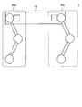
- FIG. 12 is a diagram illustrating a flow of the support start operation of the robot 1 according to the embodiment of the present disclosure.
- the robot 1 determines the support start position 41 of the support target 30 by detecting the support target 30 and starts moving to the support start position 41 (operation 1).
- the robot 1 moves to the support start position 41 (operation 2).
- the robot 1 starts crouching operation at the support start position 41 (operation 3).
- the robot 1 supports the support target 30 by the crouching operation (operation 4).
- the robot 1 starts a rising operation (operation 5).
- the robot 1 transports the support target 30 to the destination (operation 6).
- FIG. 13 is a flowchart illustrating the flow of the support start operation process in the control unit 100 according to the embodiment of the present disclosure.
- the control unit 100 detects the support target 30 based on the sensing data detected by the sensor unit 104 (step S1000).
- the control unit 100 determines the support start position 41 of the support target 30 based on the detection result of the support target 30 (step S1002).
- the control unit 100 moves the robot 1 to the support start position 41 by driving the leg 20 of the robot 1 (step S1004).
- the control unit 100 drives the leg 20 of the robot 1 at the support start position 41 to cause the robot 1 to perform a squatting operation and support the support target 30 (step S1006).
- control unit 100 After the support target 30 is supported, the control unit 100 causes the robot 1 to perform a rising operation by driving the leg unit 20 (step S1008). After the completion of the rising operation, the control unit 100 moves the robot 1 to the destination while supporting the support target 30 (step S1010).
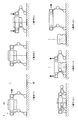
- FIG. 14 is a diagram illustrating a flow of the support end operation of the robot 1 according to the embodiment of the present disclosure.
- the robot 1 executes the operations shown in FIG. First, the robot 1 detects a destination to which the support target 30 is to be transported, thereby determining a support end position 42 at which the supported support target 30 is lowered to end support, and a support end position. The movement to 42 is started (operation 7). The robot 1 moves to the support end position 42 (operation 8). After moving to the support end position 42, the robot 1 starts crouching operation at the support end position 42 (operation 9).
- the robot 1 releases the support target 30 to terminate the support of the support target 30 (operation 10). After the support of the support target 30 is completed, the robot 1 starts a rising operation (operation 11). After standing up, the robot 1 starts moving to the position of the support target 30 to be transported next (operation 12).
- FIG. 15 is a flowchart illustrating the flow of the support end operation process in the control unit 100 according to the embodiment of the present disclosure.
- the control unit 100 detects a destination based on the sensing data detected by the sensor unit 104 (step S2000). Based on the result of the detection of the destination, the control unit 100 determines the support end position 42 of the support target 30 (Step S2002).
- the control unit 100 moves the robot 1 to the support end position 42 by driving the leg 20 of the robot 1 (step S2004).
- the control unit 100 causes the robot 1 to perform a crouching operation by driving the leg 20 of the robot 1 at the support end position 42 (step S2006).
- control unit 100 causes the robot 1 to stop supporting the support target 30 (step S2008). After the support mechanism finishes supporting the support target, the control unit 100 causes the robot 1 to perform a rising operation by driving the leg 20 of the robot 1 (step S2010). After the start-up operation is completed, the control unit 100 moves the robot 1 to the position of the support target 30 to be transported next (step S2012).
- Example An example according to the embodiment of the present disclosure will be described with reference to FIGS. 16 to 21.
- the examples described below may be applied to the embodiments of the present disclosure by themselves, or may be applied to the embodiments of the present disclosure in combination. Further, the example may be applied instead of the configuration described in the embodiment of the present disclosure, or may be additionally applied to the configuration described in the embodiment of the present disclosure.
- FIG. 16 is a diagram illustrating an example of a method for detecting the support target 30 according to the embodiment of the present disclosure.
- the robot 1 detects the support target 30 by acquiring information output by the support target 30, for example.
- the output device 33 included in the support target 30 outputs a sound wave 34 having a specific frequency known by the robot 1.
- the robot 1 includes a microphone 104a as the sensor unit 104, and acquires the sound wave 34 by the microphone 104a.
- the robot 1 detects the support target 30 based on the acquired sound waves 34. Then, the robot 1 detects a relative positional relationship between the robot 1 and the support target 30 based on the detected position of the support target 30.
- the position where the microphone 104a is installed is not limited, and is installed at an arbitrary position of the robot 1.
- the microphone 104a may be installed at a circular position on the upper surface of the main unit 10, as shown in FIG. 16, or may be set at a triangular position on the lower surface of the main unit 10.
- FIG. 17 is a diagram illustrating an example of a posture control process using communication according to the embodiment of the present disclosure.
- the robot 1 receives, for example, the support target information transmitted from the communication unit included in the support target 30 by the communication unit 102, and controls the posture of the robot 1 based on the received support target information.
- the robot 1 corrects the attitude of the robot 1 with respect to the Roll axis and the Pitch axis, for example.
- the support target 30 includes, for example, an acceleration sensor, and detects inclination information of the support target 30 with respect to the gravity 35 by the acceleration sensor. Then, the support target 30 transmits the support target information including the detected tilt information to the communication unit 102 of the robot 1 by wireless communication 36.
- FIG. 18 is a diagram illustrating an example of a posture control process using the distance measurement sensor according to the embodiment of the present disclosure.
- the robot 1 performs the posture control process based on the support target information acquired by the distance measurement sensor 104b.
- the robot 1 includes, for example, a distance measuring sensor 104 b at a circle position between a hollow front surface 113 and a hollow left side surface 116 on the inner surface of the main body.
- the robot 1 includes the distance measurement sensors 104b on at least two inner surfaces of the main body, thereby acquiring posture information of the support target 30 inserted into the hollow portion 110 on the two surfaces.
- the posture information includes, for example, an angle indicating the inclination of the support target 30.
- the robot 1 detects a relative distance and an angle between the hollow portion 110 and the support target 30 based on the acquired posture information of the support target 30. Then, the robot 1 corrects the posture of the robot 1 based on the detected relative distance and angle so that the support target 30 is inserted in conformity with the hollow portion 110. At this time, the robot 1 corrects the attitude of the robot 1 with respect to the Yaw axis, for example.
- the surface on which the distance measuring sensor 104b is installed on the inner surface of the main body is not particularly limited. Further, the position on the inner surface of the main body where the distance measuring sensor 104b is installed is not particularly limited. However, it is desirable that the distance measurement sensor 104b is not installed linearly on one of the inner surfaces of the main body. For example, as shown in FIG. 18, since the distance measuring sensor 104b is not installed on a straight line, the surface of the support target 30 is easily detected.
- FIG. 19 is a diagram illustrating an example of a posture control process using the laser light source according to the embodiment of the present disclosure.
- the robot 1 performs the posture control process based on the support target information acquired by the camera 104c and the laser light source 104d.
- the robot 1 has a camera 104c at a round position on the inner surface of the main body and a laser light source 104d at a triangular position.
- the robot 1 causes the laser light source 104d to output a linear laser beam 14 in a diagonal direction of the installation position, and causes the camera 104c to image the reflected light when the laser beam 14 is reflected by the support target 30.
- the robot 1 detects the relative position and orientation between the hollow part 110 and the support target 30 based on the image captured by the camera 104c. Then, the robot 1 corrects the posture of the robot 1 based on the detected relative position and posture so that the support target 30 is inserted in conformity with the hollow portion 110. At this time, the robot 1 corrects the attitude of the robot 1 with respect to the Yaw axis, for example.
- the surface on which the camera 104c and the laser light source 104d are installed on the inner surface of the main body is not particularly limited.
- positions on the inner surface of the main body where the camera 104c and the laser light source 104d are installed are not particularly limited.
- the laser light source 104d outputs the laser beam 14 so as not to be parallel to any side of any surface of the inner surface of the main body.
- the laser light source 104d may be provided for any side of each surface, such as the laser beam 14a applied to the front surface 113 of the hollow portion and the laser beam 14b applied to the left side surface 116 of the hollow portion shown in FIG. The laser beam 14 is output so as not to be parallel. Thereby, the surface of the support target 30 is easily detected.
- FIG. 20 is a diagram illustrating an example of correction of the inclination of the support target 30 by the protrusion 40 according to the embodiment of the present disclosure.
- the robot 1 pushes the support target 30 with the main body 10 as shown in the upper part of FIG.
- the robot 1 moves the support target 30 to a position where the tilt of the support target 30 stops as shown in the middle part of FIG.
- the robot 1 starts the support operation as shown in the lower part of FIG.
- FIG. 21 is a diagram illustrating an example of correction of the inclination of the support target 30 due to the depression according to the embodiment of the present disclosure.
- the robot 1 pushes the support target 30 with the main body 10 as shown in the upper part of FIG.
- the robot 1 moves the support target 30 to a position where the tilt of the support target 30 stops as shown in the middle part of FIG. 21.
- the robot 1 starts the support operation as shown in the lower part of FIG.
- the robot 1 determines whether or not the support target 30 is tilted, and then performs the operation of pushing the support target 30 with the main body unit 10 described above. For example, the robot 1 determines whether or not the support target 30 is tilted based on an image captured by a camera included in the sensor unit 104. Specifically, the robot 1 previously holds an image when the support target 30 is in a horizontal state in a storage unit or the like, and compares the image with an image captured by a camera, so that the support target 30 is tilted. Is determined. Further, the robot 1 may determine whether or not the support target 30 is tilted based on information sensed by an acceleration sensor included in the support target 30. Further, when determining that the support target 30 is inclined, the robot 1 may move the support target 30 by putting a bag or a net on the support target 30 and pulling the bag or the net.
- FIG. 22 is a diagram illustrating a modification according to the embodiment of the present disclosure.
- the robot 1 has the support portion 120
- the support target 30 has the concave portion 31, and the robot 1 supports the support target 30 by moving upward and downward.
- the robot 1 has the convex portion 126
- the support target 37 has the handle 38
- the robot 1 supports the support target 37 by operating in the up-down direction and the front-back direction.
- the main body 10 of the robot 1 has a convex portion 126.
- the support target 37 has a handle 38.
- the robot 1 executes the operations shown in FIG. First, the robot 1 moves to the position of the support target 37 (operation 13). Next, the robot 1 puts the handle 38a on the convex portion 126a by moving the main body 10 in combination with the vertical movement and the front-back movement (operation 14). Next, the robot 1 moves the protrusion 126b to the lower side of the handle 38b by moving the main body 10 in combination with the movement in the up-down direction and the movement in the front-rear direction (operation 15). Then, the robot 1 places the handle 38 on the projection 126b by moving the main body 10 upward (operation 16). The robot 1 can lift the support target 37 by further performing an upward operation in a state where the operation 16 is completed.
- FIG. 23 is a block diagram illustrating a hardware configuration example of the robot 900 according to the present embodiment.
- Information processing in the robot 900 according to the present embodiment is realized by cooperation between software and hardware described below.
- the robot 900 includes a CPU (Central Processing Unit) 901, a ROM (Read Only Memory) 903, and a RAM (Random Access Memory) 905.
- the robot 900 includes a host bus 907, a bridge 909, an external bus 911, an interface 913, an input device 915, a storage device 917, and a communication device 919.
- the hardware configuration shown here is an example, and some of the components may be omitted. Further, the hardware configuration may further include components other than the components shown here.
- the CPU 901 functions as, for example, an arithmetic processing device or a control device, and controls the entire operation of each component or a part thereof based on various programs recorded in the ROM 903, the RAM 905, or the storage device 917.
- the ROM 903 is a unit that stores programs read by the CPU 901, data used for calculations, and the like.
- the RAM 905 temporarily or permanently stores, for example, a program read by the CPU 901 and various parameters that appropriately change when the program is executed. These are mutually connected by a host bus 907 including a CPU bus and the like.
- the CPU 901, the ROM 903, and the RAM 905 can realize the function of the control unit 100 described with reference to FIG. 10, for example, in cooperation with software.
- the CPU 901, the ROM 903, and the RAM 905 are connected to each other via a host bus 907 capable of high-speed data transmission, for example.
- the host bus 907 is connected to, for example, an external bus 911 having a relatively low data transmission speed via a bridge 909.
- the external bus 911 is connected to various components via an interface 913.
- the input device 915 is realized by a device to which information is input by a user, such as a mouse, a keyboard, a touch panel, a button, a microphone, a switch, and a lever. Further, the input device 915 may be, for example, a remote control device using infrared rays or other radio waves, or may be an externally connected device such as a mobile phone or a PDA compatible with the operation of the robot 900. Further, the input device 915 may include, for example, an input control circuit that generates an input signal based on information input by a user using the above-described input unit and outputs the input signal to the CPU 901. By operating the input device 915, the user of the robot 900 can input various data to the robot 900 and instruct a processing operation.
- the input device 915 may be formed by a device that detects information about a user.
- the input device 915 includes various sensors such as an image sensor (for example, a camera), a depth sensor (for example, a stereo camera), an acceleration sensor, a gyro sensor, a geomagnetic sensor, an optical sensor, a sound sensor, a distance measuring sensor, and a force sensor. May be included.
- the input device 915 may acquire information on the state of the robot 900 itself, such as the posture and the moving speed of the robot 900, and information on the surrounding environment of the robot 900, such as brightness and noise around the robot 900.
- the input device 915 receives a GNSS signal from a GNSS (Global Navigation Satellite System) satellite (for example, a GPS signal from a GPS (Global Positioning System) satellite) and receives position information including the latitude, longitude, and altitude of the device.
- GNSS Global Navigation Satellite System
- a GNSS module for measuring may be included.
- the input device 915 may be a device that detects the position by Wi-Fi (registered trademark), transmission / reception with a mobile phone / PHS / smartphone, or the like, or short-range communication.
- the input device 915 can realize, for example, the function of the sensor unit 104 described with reference to FIG.
- the storage device 917 is a device for storing data formed as an example of a storage unit of the robot 900.
- the storage device 917 is realized by, for example, a magnetic storage device such as an HDD, a semiconductor storage device, an optical storage device, or a magneto-optical storage device.
- the storage device 917 may include a storage medium, a recording device that records data on the storage medium, a reading device that reads data from the storage medium, a deletion device that deletes data recorded on the storage medium, and the like.
- the storage device 917 stores programs executed by the CPU 901 and various data, various data acquired from the outside, and the like.
- the storage device 917 can realize, for example, the function of the storage unit 106 described with reference to FIG.
- the communication device 919 is, for example, a communication interface formed by a communication device or the like for connecting to the network 921.
- the communication device 919 is, for example, a communication card for a wired or wireless LAN (Local Area Network), LTE (Long Term Evolution), Bluetooth (registered trademark), or WUSB (Wireless USB).
- the communication device 919 may be a router for optical communication, a router for ADSL (Asymmetric Digital Subscriber Line), a modem for various kinds of communication, or the like.
- the communication device 919 can transmit and receive signals and the like to and from the Internet and other communication devices in accordance with a predetermined protocol such as TCP / IP.
- the network 921 is a wired or wireless transmission path for information transmitted from a device connected to the network 921.
- the network 921 may include a public line network such as the Internet, a telephone line network, and a satellite communication network, various LANs including Ethernet (registered trademark) (Local Area Network), a WAN (Wide Area Network), and the like.
- the network 921 may include a dedicated line network such as an IP-VPN (Internet ⁇ Protocol-Virtual ⁇ Private ⁇ Network).
- the robot 1 has the hollow portion 110 that is a hollow space penetrating in the vertical direction, and the support target inserted into the hollow portion 110 as the robot moves in the vertical direction.
- the main body 10 is provided for lifting and supporting the main body 30.
- the robot 1 includes a movable unit that moves the main unit 10 at least in the vertical direction by operating the leg unit 20.
- the robot 1 can load and unload and carry a load without providing an arm device outside the main body 10.
- a body portion having a hollow portion that is a hollow space penetrating in the up-down direction, and lifting and supporting a support target inserted into the hollow portion along with the up-down movement, A movable unit configured to move the main unit at least in the vertical direction by operating a leg unit.
- the robot according to (1) wherein the main body section moves the at least downward direction when the main body section is positioned above the support target, thereby inserting the support target into the hollow portion.
- the main body has a support for supporting the support target, The robot according to (1) or (2), wherein the support unit supports the support target when the support target is inserted into the hollow portion.
- the robot according to (3) wherein the support unit has a movable claw, and supports the support target by engaging the claw with the support target.
- the shape of the hollow portion is a wedge shape, The robot according to any one of (1) to (5), wherein the wedge shape is formed by different areas of the first opening and the second opening of the hollow portion. . (7) The robot according to any one of (1) to (6), wherein the position of the center of gravity of the hollow portion is a position within a predetermined range from the position of the center of gravity of the main body.
- the legs are composed of a plurality of links and a plurality of movable parts, and perform bending and stretching movements by operating the movable parts to move the main body at least in the vertical direction.
- the robot according to any one of the above.
- a control method executed by a processor including: (12) The processor according to (11), wherein, based on the support target information, the processor detects a position of the support target, and determines the detected position of the support target as an execution position of the operation in the upward direction and the downward direction. The control method described. (13) The control method according to (12), wherein the processor moves the control target to the execution position and causes the control target to execute the upward and downward operations.
- the processor detects a positional relationship between the hollow portion and the support target based on the support target information, and detects a difference between the attitude of the support target and the attitude of the control target based on the positional relationship, The control method according to any one of (11) to (13).
- Method (16) The processor according to any one of (11) to (15), wherein, when the control target performs the downward operation, the processor starts or ends the support of the support target by the support unit of the control target.
- the processor when the support unit does not support the support target, by causing the control target to perform an operation from the top of the support target to the downward direction, the support unit to support the support target.
- (19) The control method according to any one of (11) to (18), wherein the processor causes the sensor unit included in the control target to sense the support target to acquire the support target information.
- the processor causes the communication unit included in the control target to perform communication with the communication unit of the support target to acquire the support target information.
Abstract
上下方向に貫通する中空な空間である中空部(110)を有し、前記上下方向への移動に伴い前記中空部(110)に挿入される支持対象(30)を持ち上げて支持する本体部(10)と、脚部(20)を動作させることで前記本体部(10)を少なくとも前記上下方向に移動させる可動部(200)と、を備えるロボット(1)。
Description
本開示は、ロボット、及び制御方法に関する。
一般的な荷物運搬用ロボットは、荷物を荷台に積み、運搬先へ移動し、荷物を荷台から下ろすという一連の作業を行うことで荷物の運搬を行う。荷物の積み下ろしは、荷物運搬用ロボットが備えるアーム、または外部に設置されているアーム装置等により行われる。運搬先への移動は、脚部等の移動機構により行われる。このように、一般的な荷物運搬用ロボットは、作業に応じて機構が分けられている。そのため、当該荷物運搬用ロボットが上記の作業を行うためには、荷物の積み下ろし時にアーム装置を動作させるためのスペースと、荷物の運搬時に移動するためのスペースとが必要である。しかしながら、荷物運搬用ロボットが作業スペースを十分に確保できない場合、荷物運搬用ロボットによる荷物の運搬は困難となる。そのため、荷物運搬用ロボットは、よりシンプルな構成かつより小さい荷物運搬用ロボットであることにより、より小さな作業スペースで作業できることが望ましい。
例えば、下記特許文献1には、胴部への運搬物の積み込み、及び胴部からの運搬物の積み下ろしを脚部により行い、運搬先への移動も脚部により行う脚式移動ロボットが開示されている。当該脚式移動ロボットは、脚部がアーム機構と移動機構を兼ねているため、一般的な荷物運搬用ロボットと比較してよりシンプルな構成となっている。
しかしながら、上記の脚式移動ロボットの脚部は、脚式移動ロボットの外部に備えられている。また、荷物の積み下ろしを行う際の動作は、一般的な荷物運搬用ロボットと同様な動作である。そのため、脚式移動ロボットが作業に必要とするスペースの縮小化は、あまり期待されない。
そこで、本開示では、荷物運搬用ロボットの小型化及び作業スペースの縮小化が可能な、新規かつ改良されたロボット、及び制御方法を提案する。
本開示によれば、上下方向に貫通する中空な空間である中空部を有し、前記上下方向への移動に伴い前記中空部に挿入される支持対象を持ち上げて支持する本体部と、脚部を動作させることで前記本体部を少なくとも前記上下方向に移動させる可動部と、を備えるロボットが提供される。
また、本開示によれば、支持対象に関する支持対象情報に基づき、中空な空間である中空部を有する制御対象の少なくとも上方向及び下方向への動作を制御することと、前記中空部に挿入された前記支持対象に対する前記制御対象の支持動作を制御することと、を含むプロセッサにより実行される制御方法が提供される。
以上説明したように本開示によれば、荷物運搬用ロボットの小型化及び作業スペースの縮小化が可能なロボット、及び制御方法が提供される。なお、上記の効果は必ずしも限定的なものではなく、上記の効果とともに、または上記の効果に代えて、本明細書に示されたいずれかの効果、または本明細書から把握され得る他の効果が奏されてもよい。
以下に添付図面を参照しながら、本開示の好適な実施の形態について詳細に説明する。なお、本明細書及び図面において、実質的に同一の機能構成を有する構成要素については、同一の符号を付することにより重複説明を省略する。
なお、説明は以下の順序で行うものとする。
1.本開示の実施形態
1.1.概要
1.2.外部構成例
1.3.機能構成例
1.4.動作例
2.実施例
3.変形例
4.ハードウェア構成例
5.まとめ
1.本開示の実施形態
1.1.概要
1.2.外部構成例
1.3.機能構成例
1.4.動作例
2.実施例
3.変形例
4.ハードウェア構成例
5.まとめ
<<1.本開示の実施形態>>
<1.1.概要>
一般的な荷物運搬用ロボットは、荷物を荷台に積み、運搬先へ移動し、荷物を荷台から下ろすという一連の作業を行うことで荷物の運搬を行う。荷物の積み下ろしは、荷物運搬用ロボットが備えるアーム、または外部に設置されているアーム装置等により行われる。運搬先への移動は、脚部等の移動機構により行われる。このように、一般的な荷物運搬用ロボットは、作業に応じて機構が分けられている。そのため、当該荷物運搬用ロボットが上記の作業を行うためには、荷物の積み下ろし時にアーム装置を動作させるためのスペースと、荷物の運搬時に移動するためのスペースとが必要である。しかしながら、荷物運搬用ロボットが作業スペースを十分に確保できない場合、荷物運搬用ロボットによる荷物の運搬は困難となる。そのため、荷物運搬用ロボットは、よりシンプルな構成かつより小さい荷物運搬用ロボットであることにより、より小さな作業スペースで作業できることが望ましい。
上記の事情を一着眼点にし、本開示の実施形態に係るロボットが創作されるに至った。本実施形態に係るロボットは、本体部、可動部、及び複数の脚部を備える。本体部は、上下方向に貫通する中空な空間である中空部を有する。可動部は、自身が駆動することにより複数の脚部の各々を動作させる。本体部は、複数の脚部の各々と連結されているため、可動部の駆動により複数の脚部の各々が動作することに伴い、少なくとも上下方向に動作する。本体部は、上下方向に動作することにより、中空部に支持対象(例えば荷物)を挿入し、挿入された支持対象を持ち上げて支持することができる。なお、可動部の駆動に伴う本体部の上下方向への動作、及び支持対象に対する本体部の支持動作は、支持対象に関する支持対象情報に基づき制御される。支持対象情報は、例えば、支持対象の位置に関する情報、及び支持対象の傾き等の姿勢に関する情報等を含み得る。
また、可動部は、可動部単体として実現されてもよいし、脚部の関節部が可動部としての機能を有するものとして実現されてもよい。本実施形態では、関節部が可動部としての機能を有する例について説明する。また、本実施形態に係る支持対象は、本体部10が支持可能な形状である専用コンテナが用いられる。
これにより、本実施形態に係るロボットは、アーム装置を用いることなく荷物の積み下ろしを行うことができる。よって、アーム装置が設けられない分だけロボットを小型化することができる。また、本実施形態に係るロボットは、上下方向の動作のみで荷物の積み下ろしを行うことができる。よって、アーム装置を用いて荷物の積み下ろしを行う場合と比較して、作業スペースを縮小化することができる。以下、本実施形態の内容について順次詳細に説明する。
<1.2.外部構成例>
以下では、図1~図9を参照しながら、本開示の実施形態に係るロボット1の外部構成例について説明する。図1は、本開示の実施形態に係るロボット1を上から見た際の外観の概略図である。図2は、本開示の実施形態に係るロボット1を右側から見た際の外観の概略図である。図1、及び図2に示すように、ロボット1は、本体部10、及び4脚の脚部20を備える。本体部10は、上下方向に貫通する中空な空間である中空部110を有する。4脚の脚部20は、それぞれ脚部20a、脚部20b、脚部20c、及び脚部20dである。また、4脚の脚部20の各々は、本体部10に対して取り外し可能に構成され得る。
以下では、図1~図9を参照しながら、本開示の実施形態に係るロボット1の外部構成例について説明する。図1は、本開示の実施形態に係るロボット1を上から見た際の外観の概略図である。図2は、本開示の実施形態に係るロボット1を右側から見た際の外観の概略図である。図1、及び図2に示すように、ロボット1は、本体部10、及び4脚の脚部20を備える。本体部10は、上下方向に貫通する中空な空間である中空部110を有する。4脚の脚部20は、それぞれ脚部20a、脚部20b、脚部20c、及び脚部20dである。また、4脚の脚部20の各々は、本体部10に対して取り外し可能に構成され得る。
当該4脚の脚部20の種類は、全て同一であり得る。ただし、係る例に限定されず、例えば軸構成などの種類が互いに異なる脚部20が併用されてもよい。また、当該脚部20の数は、4脚に限定されない。例えば、脚部20の数は、2脚又は6脚等であってもよい。
なお、当該ロボット1において、切断線I-Iに対して脚部20c及び脚部20dがある側が本体部10の右側、脚部20a及び脚部20bがある側が本体部10の左側である。また、当該ロボット1において、切断線II-IIに対して脚部20b及び脚部20dがある側が本体部10の前側、脚部20a及び脚部20cがある側が本体部10の後側である。
(1)本体部10
以下では、図3及び図4を参照しながら、本体部10の詳細を説明する。図3は、本開示の実施形態に係る本体部10を長辺方向に切断した断面を示す図(図1に示す切断線I-Iにおける断面図)である。図4は、本開示の実施形態に係る本体部10を短辺方向に切断した断面を示す図(図1に示す切断線II-IIにおける断面図)である。
以下では、図3及び図4を参照しながら、本体部10の詳細を説明する。図3は、本開示の実施形態に係る本体部10を長辺方向に切断した断面を示す図(図1に示す切断線I-Iにおける断面図)である。図4は、本開示の実施形態に係る本体部10を短辺方向に切断した断面を示す図(図1に示す切断線II-IIにおける断面図)である。
図3、図4に示すように、本体部10は、中空部110、及び支持部120を有する。本体部10は、中空部110に支持対象を挿入し、支持部120で支持対象を支持する。具体的に、本体部10は、支持対象の上に位置する際に、少なくとも下方向へ移動することで、支持対象を中空部110へ挿入する。次いで、支持部120は、本体部10により中空部110に挿入された支持対象を支持する。そして、本体部10は、支持部120が支持対象を支持した際に、少なくとも上方向へ移動することで、支持対象を持ち上げて支持する。
(1-1)中空部110
中空部110は、本体部10を上下方向に貫通する中空な空間である。例えば、中空部110は、本体部10の上面と下面とを貫通する空間である。具体的に、中空部110は、本体部の10の上面の開口部111(第1の開口部)と本体部10の下面の開口部112(第2の開口部)との間を貫通する空間である。
中空部110は、本体部10を上下方向に貫通する中空な空間である。例えば、中空部110は、本体部10の上面と下面とを貫通する空間である。具体的に、中空部110は、本体部の10の上面の開口部111(第1の開口部)と本体部10の下面の開口部112(第2の開口部)との間を貫通する空間である。
(中空部110の形状)
中空部110の形状は、例えば、くさび形である。当該くさび形は、例えば、開口部111の面積と開口部112の面積とが異なることで形成される。具体的に、当該くさび形は、開口部111の面積が開口部112の面積より小さいことにより形成され、開口部112から開口部111に向けて細くなる形状となる。中空部110の形状がくさび形であることより、本体部10の内側の中空部前面113、中空部後面114、中空部右側面115、及び中空部左側面116(以下では、まとめて本体部内面とも称される)には傾斜が生じる。当該傾斜は、以下では、本体部内面の傾斜とも称される。本体部10は、中空部110へ支持対象30を挿入する際に、中空部110の傾斜を利用することで中空部110への支持対象30の挿入を円滑に行うことができる。なお、中空部の形状はくさび形に限定されず任意の形状であってもよいが、支持対象30の挿入の円滑化のためにくさび形であることが望ましい。
中空部110の形状は、例えば、くさび形である。当該くさび形は、例えば、開口部111の面積と開口部112の面積とが異なることで形成される。具体的に、当該くさび形は、開口部111の面積が開口部112の面積より小さいことにより形成され、開口部112から開口部111に向けて細くなる形状となる。中空部110の形状がくさび形であることより、本体部10の内側の中空部前面113、中空部後面114、中空部右側面115、及び中空部左側面116(以下では、まとめて本体部内面とも称される)には傾斜が生じる。当該傾斜は、以下では、本体部内面の傾斜とも称される。本体部10は、中空部110へ支持対象30を挿入する際に、中空部110の傾斜を利用することで中空部110への支持対象30の挿入を円滑に行うことができる。なお、中空部の形状はくさび形に限定されず任意の形状であってもよいが、支持対象30の挿入の円滑化のためにくさび形であることが望ましい。
中空部110への支持対象の円滑な挿入について、図5を参照しながら具体的に説明する。図5は、本開示の実施形態に係る中空部110への支持対象30の挿入例を示す図である。図5の左側に示す図は、挿入前の支持対象30の状態を示す図であり、図5の右側に示す図は、挿入後の支持対象30の状態を示す図である。また、図5の左側及び右側の上部の図は、ロボット1を上から見た図であり、図5の左側及び右側の下部の図は、図1に示す切断線I-Iの断面位置における支持対象30の状態を示す図である。
支持対象30の位置及び向きは、本体部10が下方向に移動した際に支持対象30が本体部内面と接触することなく開口部111に嵌まる位置及び向きであることが望ましい。なぜならば、支持対象30が本体部内面に接触した場合、例えば、支持対象30が開口部111まで挿入されず、本体部10が支持対象を支持できない可能性があるからである。その場合、本体部10は、中空部110へ支持対象30を挿入する動作をやり直す必要があり、これは非効率的である。具体的に、支持対象30の位置及び向きが図5の左側の図に示す位置及び向きである場合、本体部10が下方向に移動すると、支持対象30の上部の一部が中空部後面114に接触してしまう。しかしながら、支持対象30が本体部内面に接触した状態で、本体部10が下方向への移動を継続すると、支持対象30は、本体部内面の傾斜を押し当てられることで、本体部内面の傾斜に沿って移動又は回転する。そして、図5の右側の図に示すように、支持対象30の位置及び向きは、最終的に、支持対象30が開口部111に嵌まることができる位置及び向きとなる。
上述の例では、支持対象30の位置及び向きは、支持対象30が本体部内面と接触する位置及び向きである例について説明した。なお、支持対象30の位置又は向きの少なくともいずれか一方が、支持対象30が本体部内面に接触する位置又は向きであってもよい。
(中空部110の重心位置)
本体部10は、支持対象30を本体部10の重心の近傍で支持することで、支持対象30を安定して支持及び運搬することができる。そのため、中空部110は、本体部10が本体部10の重心の近傍で支持対象30を支持できる位置に形成されることが望ましい。ロボット1は、本体部10の重心の近傍で支持対象30を支持することで、関節トルクの偏り、左右前後のトルクの偏り等を減少し、ロボット1の姿勢の安定性を向上することができる。
本体部10は、支持対象30を本体部10の重心の近傍で支持することで、支持対象30を安定して支持及び運搬することができる。そのため、中空部110は、本体部10が本体部10の重心の近傍で支持対象30を支持できる位置に形成されることが望ましい。ロボット1は、本体部10の重心の近傍で支持対象30を支持することで、関節トルクの偏り、左右前後のトルクの偏り等を減少し、ロボット1の姿勢の安定性を向上することができる。
中空部の重心の位置について、図6を参照しながら具体的に説明する。図6は、本開示の実施形態に係る支持された支持対象30の重心の位置の例を示す図である。図6の上部に示す図は、ロボット1を上から見た図である。また、図6の下部に示す図は、ロボット1を右側から見た図である。
図6に示す例では、ロボット1が支持対象30を支持した際の支持対象30の重心32の位置は、本体部10の重心12の位置から所定の範囲13の内に位置している。このように、支持対象30の重心32の位置を所定の範囲13の内に位置させるためには、中空部110の重心の位置も本体部10の重心12の位置から所定の範囲13の内に位置するように、中空部110を形成するとよい。図6に示す例では、中空部110は、中空部110の重心(図示しない)の位置が本体部10の重心12と同一の位置となるように形成されている。
(1-2)支持部120
支持部120は、支持対象30を支持する機能を有する。支持部120は、例えば、爪122と軸部124で構成され、支持対象30に爪122を係合させることで支持対象30を支持する。爪122は、可動する軸部124と接続されており、当該軸部124の動作に伴い動作する。爪122の形状は、例えば、矩形である。軸部124は、本体部内面に設けられる。軸部124は、例えば、ばね等の弾性体を有し、当該ばねの弾性力を利用して動作することで爪122を動かし、爪122と支持対象30とを係合させる。爪122と支持対象30とが係合した際に、支持部120は、ラッチ機構により爪122を固定することで、支持対象30を固定して支持してもよい。本実施形態では、図3に示すように、2つの支持部120a及び支持部120bがそれぞれ中空部前面113及び中空部後面114に設けられる。なお、支持部120の構成、数、及び設置位置は上述の例に限定されない。例えば、支持部120は、磁力又は空気圧により支持対象30を吸着することで、支持対象30を支持する構成であってもよい。
支持部120は、支持対象30を支持する機能を有する。支持部120は、例えば、爪122と軸部124で構成され、支持対象30に爪122を係合させることで支持対象30を支持する。爪122は、可動する軸部124と接続されており、当該軸部124の動作に伴い動作する。爪122の形状は、例えば、矩形である。軸部124は、本体部内面に設けられる。軸部124は、例えば、ばね等の弾性体を有し、当該ばねの弾性力を利用して動作することで爪122を動かし、爪122と支持対象30とを係合させる。爪122と支持対象30とが係合した際に、支持部120は、ラッチ機構により爪122を固定することで、支持対象30を固定して支持してもよい。本実施形態では、図3に示すように、2つの支持部120a及び支持部120bがそれぞれ中空部前面113及び中空部後面114に設けられる。なお、支持部120の構成、数、及び設置位置は上述の例に限定されない。例えば、支持部120は、磁力又は空気圧により支持対象30を吸着することで、支持対象30を支持する構成であってもよい。
支持部120による支持対象30の支持について、図7を参照しながら具体的に説明する。図7は、本開示の実施形態に係る支持部120による支持対象30の支持例を示す図である。図7の左側に示す図は、支持前の支持部120の状態を示す図であり、図7の右側に示す図は、支持後の支持部120の状態を示す図である。
支持部120は、本体部10の下方向への移動に伴い下方向へ移動することで、爪122を支持対象30の凹部にかけることで、支持対象30と係合する。図7に示すように、本体部10は、下方向に移動することで中空部110へ支持対象30を挿入する。本体部10の下方向への移動に伴い、支持部120の爪122は、支持対象30と接触する。爪122が支持対象と接触して以降も本体部10が下方向への移動を継続すると、爪122は、支持対象30により押し上げられる。爪122が押し上げられた状態で本体部10がさらに下方向へ移動することで、爪122は、支持対象30の凹部31の位置まで移動する。爪122は、当該凹部31の位置まで移動すると、図7の右側の図に示すように凹部31と係合する。これにより、支持部120は、支持対象30を支持することができる。
支持部120は、支持対象30の支持の終了にあたり、支持部120と支持対象30との係合を解除する構成として、多様な構成を有し得る。例えば、支持部120は、アクチュエータを有してもよい。支持部120は、当該アクチュエータを駆動させることで爪122を動かし、爪122と凹部31との係合を解除してもよい。また、支持部120は、本体部10の移動に伴い支持部120と支持対象30との係合が解除される機構を有してもよい。
(2)脚部20
以下では、図8、図9を参照しながら、本開示の実施形態に係る脚部20の外部構成例について説明する。図8は、本開示の実施形態に係る脚部20の外部構成例を示す図である。図9は、本開示の実施形態に係る脚部20を上から見た際の軸構成の概略を示す図である。
以下では、図8、図9を参照しながら、本開示の実施形態に係る脚部20の外部構成例について説明する。図8は、本開示の実施形態に係る脚部20の外部構成例を示す図である。図9は、本開示の実施形態に係る脚部20を上から見た際の軸構成の概略を示す図である。
図8に示すように、脚部20は、例えば、複数の関節部200(可動部)と複数のリンク204とを含むリンク機構として構成され得る。脚部20は、複数の関節部200として、Roll軸方向に回転する股関節Roll軸200a、Pitch軸方向に回転する股関節Pitch軸200b、及びPitch軸方向に回転する膝関節Pitch軸200c関節部200を有する。関節部200の各々は、内部にアクチュエータを有しており、当該アクチュエータが駆動することで、各々の軸方向に回転する。図9に示すように、股関節Pitch軸200bの回転軸と、膝関節Pitch軸200cの回転軸とが同軸になるように、これらの関節部200は配置されてもよい。
また、脚部20は、股関節Roll軸200aと股関節Pitch軸200bとを連結するリンク204aを有する。また、脚部20は、股関節Pitch軸200bおよび膝関節Pitch軸200cに連結する閉リンク機構206を有してもよい。これにより、股関節Pitch軸200bを駆動するアクチュエータにより出力される力が膝関節Pitch軸200cへ伝達され得る。
また、脚部20は、足先202(先端部)を有する。足先202は、閉リンク機構206に含まれるリンク204bの先端に設けられる。足先202は、ロボット1が移動する移動路面と接触している。足先202は、足先202と移動路面との間に適度な摩擦が生じるように、エラストマー等でおおわれている。また、足先202には、車輪が設けられてもよい。これにより、ロボット1は、移動路面をより滑らかに、かつ高速に移動することができる。また、各脚部20には、足先202と移動路面との接触状態、足先202と支持対象30等の物体との接触状態等を検出するためのセンサが備えられてもよい。
脚部20が上述のように構成されることにより、ロボット1は、脚部20ごとに、本体部10に対する当該脚部20の固定位置(例えば、股関節Roll軸200aの位置など)から見たときの、当該脚部20の足先202の位置を、縦、横、および、高さの三方向へ移動させることができる。これにより、ロボット1(より詳細には本体部10)は、各脚部20の位置および姿勢を変化させることにより、外界の任意の方向に対して力を加えることができる。また、本体部10は、例えば各脚部20が他の物体と接触した際の摩擦力の大きさに応じて、各脚部20による力のモーメントを変化させることができる。さらに、各脚部20の足先軌道が3次元の自由軌道になり得るので、ロボット1は、一以上の障害物を乗り越えたり、回避することもできる。
また、脚部20は、関節部200が動作することで屈伸運動を行い、当該屈伸運動に伴い、本体部10を少なくとも上下方向へ移動させる。ロボット1は、本体部10の支持部が支持対象30を支持した状態で、脚部20に屈伸運動を行わせ、本体部10を上下方向に移動させることにより、支持対象30を持ち上げたり、降ろしたりすることができる。また、ロボット1は、支持対象30を持ち上げて支持した状態で、脚部20を動作させて移動することで、支持対象30を運搬することができる。
なお、脚部20の構成は、屈伸運動により本体部10を上下方向へ移動させる構成に限定されない。例えば、脚部20の構成は、直動運動により本体部10を上下方向へ移動させる構成であってもよい。
なお、本実施形態に係る脚部20の軸構成は、上述した例に限定されない。例えば、脚部20の軸の数は一以上の任意の数(例えば1軸や10軸など)であってもよい。また、脚部20に含まれるリンク機構としては、全てシリアルリンクが用いられてもよいし、全てパラレルリンクが用いられてもよいし、または、一以上のシリアルリンクおよび一以上のパラレルリンクが混在していてもよい。さらに、脚部20は、劣駆動関節(つまり、アクチュエータにより駆動されない関節)を一以上有してもよい。また、脚部20が有するアクチュエータの数(脚部20が制御可能なアクチュエータの数)に関しても特に限定されない。
<1.3.機能構成例>
以下では、図10及び図11を参照しながら、本開示の実施形態に係る本体部10の機能構成例について説明する。図10は、本開示の実施形態に係る本体部10の機能構成例を示すブロック図である。図10に示すように、本開示の実施形態に係るロボット1は、制御部100、通信部102、センサ部104、及び記憶部106を備える。
以下では、図10及び図11を参照しながら、本開示の実施形態に係る本体部10の機能構成例について説明する。図10は、本開示の実施形態に係る本体部10の機能構成例を示すブロック図である。図10に示すように、本開示の実施形態に係るロボット1は、制御部100、通信部102、センサ部104、及び記憶部106を備える。
(1)制御部100
制御部100は、ロボット1の動作を制御する機能を有する。ロボット1の動作を制御するにあたり、制御部100が実行する処理ついて詳細に説明する。
制御部100は、ロボット1の動作を制御する機能を有する。ロボット1の動作を制御するにあたり、制御部100が実行する処理ついて詳細に説明する。
(1-1)検出処理
制御部100は、取得した情報に基づく検出処理を行う。例えば、制御部100は、ロボット1の本体部10が備える通信部102に支持対象30の通信部と通信を行わせることで支持対象情報を取得させる。そして、制御部100は、通信部102が取得した支持対象情報に基づき、支持対象30の位置を検出する。また、制御部100は、ロボット1の本体部10が備えるセンサ部104に支持対象30をセンシングさせることで支持対象情報を取得させる。そして、制御部100は、センサ部104が取得した支持対象情報に基づき、支持対象30の位置を検出する。また、制御部100は、通信部102又はセンサ部104が取得した支持対象情報に基づき、支持対象30の運搬先である目的地を検出する。また、制御部100は、通信部102又はセンサ部104が取得した支持対象情報に基づき、ロボット1の姿勢を検出する。
制御部100は、取得した情報に基づく検出処理を行う。例えば、制御部100は、ロボット1の本体部10が備える通信部102に支持対象30の通信部と通信を行わせることで支持対象情報を取得させる。そして、制御部100は、通信部102が取得した支持対象情報に基づき、支持対象30の位置を検出する。また、制御部100は、ロボット1の本体部10が備えるセンサ部104に支持対象30をセンシングさせることで支持対象情報を取得させる。そして、制御部100は、センサ部104が取得した支持対象情報に基づき、支持対象30の位置を検出する。また、制御部100は、通信部102又はセンサ部104が取得した支持対象情報に基づき、支持対象30の運搬先である目的地を検出する。また、制御部100は、通信部102又はセンサ部104が取得した支持対象情報に基づき、ロボット1の姿勢を検出する。
上述の通信により取得される支持対象情報は、例えば、支持対象30の位置情報である。当該位置情報は、支持対象30に記憶装置等を備えることで当該記憶装置に予め登録された位置情報でもよいし、支持対象30にGPS(Grobal Positioning System)を備えることで逐次取得される位置情報であってもよい。また、上述のセンシングにより取得される情報は、例えばロボット1から支持対象30までの距離である。当該距離は、センサ部104が備えるカメラ、又は測距装置等によりセンシングされることで検出される。また、支持対象30は、QRコード(登録商標)を備えてもよい。制御部100は、センサ部104のカメラで当該QRコードを読み込むことにより、支持対象情報を取得してもよい。
(1-2)決定処理
制御部100は、検出処理にて検出された情報に基づく決定処理を行う。例えば、制御部100は、検出処理にて検出された支持対象30の位置に基づき、当該支持対象30の位置をロボット1による上方向及び下方向への動作の実行位置として決定する。なお、以下では、ロボット1による上方向への動作は立ち上がり動作、ロボット1による下方向への動作はしゃがみ込み動作とも称される。当該支持対象30の位置は、即ちロボット1が支持対象30の支持を開始する支持開始位置である。また、制御部100は、検出処理にて検出された目的地に基づき、当該目的地をロボット1による上方向及び下方向への動作の実行位置として決定する。当該目的地は、即ちロボット1が支持対象30の支持を終了する支持終了位置である。
制御部100は、検出処理にて検出された情報に基づく決定処理を行う。例えば、制御部100は、検出処理にて検出された支持対象30の位置に基づき、当該支持対象30の位置をロボット1による上方向及び下方向への動作の実行位置として決定する。なお、以下では、ロボット1による上方向への動作は立ち上がり動作、ロボット1による下方向への動作はしゃがみ込み動作とも称される。当該支持対象30の位置は、即ちロボット1が支持対象30の支持を開始する支持開始位置である。また、制御部100は、検出処理にて検出された目的地に基づき、当該目的地をロボット1による上方向及び下方向への動作の実行位置として決定する。当該目的地は、即ちロボット1が支持対象30の支持を終了する支持終了位置である。
(1-3)動作制御処理
制御部100は、ロボット1の動作制御処理を行う。制御部100は、例えば、ロボット1を移動させる処理を行う。具体的に、制御部100は、決定処理にて決定された実行位置へロボット1を移動させる。
制御部100は、ロボット1の動作制御処理を行う。制御部100は、例えば、ロボット1を移動させる処理を行う。具体的に、制御部100は、決定処理にて決定された実行位置へロボット1を移動させる。
また、制御部100は、実行位置にてロボット1を上方向及び下方向へ動作させる処理を行う。具体的に、制御部100は、ロボット1が実行位置に移動した際に、ロボット1を下方向へ動作させる。一方、制御部100は、ロボット1が実行位置にて支持対象30の支持を開始又は終了した際に、ロボット1を上方向へ動作させる。
また、制御部100は、ロボット1の支持動作を制御する処理を行う。例えば、ロボット1が下方向への動作を実行した際に、ロボット1が有する支持部120に支持対象30の支持を開始又は終了させる。具体的に、支持部120が支持対象30を支持していない場合、制御部100は、ロボット1に支持対象30の上から下方向への動作を実行させる。そして、制御部100は、ロボット1の下方向への移動させるに伴い、支持部120を支持対象の凹部に係合させることで、支持部120に支持対象30の支持を開始させる。また、支持部120が支持対象を支持している場合、制御部100は、ロボット1に下方向への動作を実行させ、支持対象30を接地させる。そして、制御部100は、支持部120に支持対象30の凹部との係合を解除させることで、支持対象30の支持を終了させる。この時、制御部100は、例えば、支持部120が有する機構をロボット1の動作に伴い動作させることで、支持部120に支持対象30の凹部との係合を解除させる。また、制御部100は、支持部120の軸部124が有するアクチュエータを駆動させることで支持部120を動かし、支持部120に支持対象30の凹部との係合を解除させてもよい。
また、制御部100は、ロボット1の姿勢を制御する処理を行う。例えば、制御部100は、検出処理にて検出された支持対象情報に基づき、中空部110と支持対象30との位置関係を検出し、当該位置関係に基づき、支持対象30の姿勢とロボット1の姿勢との差分を検出する。次いで、制御部100は、検出した差分に基づき、ロボット1が中空部110に支持対象30を挿入しやすい姿勢となるように、ロボット1の姿勢を支持対象30の姿勢に合わせて補正する。そして、制御部100は、補正後の姿勢の状態でロボット1を下方向へ動作させる。
制御部100によるロボット1の姿勢の補正例について、図11を参照しながら説明する。図11は、本開示の実施形態に係るロボット1の姿勢制御処理の例を示す図である。図11の左側に示す図は、補正前のロボット1の姿勢を示す図である。図11の右側に示す図は、補正後のロボット1の姿勢を示す図である。図11の左側の図が示すように、例えば、支持対象30が突起物40により地面に対して傾いているとする。この時、ロボット1は、検出処理にて検出された支持対象情報に基づき、支持対象30の傾きを検出する。図11の右側の図に示すように、ロボット1は、例えば、ロボット1の本体部10と支持対象30の上面とが水平となるように、検出した傾きに応じてロボット1を傾けることでロボット1の姿勢を補正する。そして、ロボット1は、補正後の姿勢のまま下方向への動作を行う。
(2)通信部102
通信部102は、外部装置との通信を行う機能を有する。例えば、通信部102は、支持対象30が備える通信部と通信を行うことで、情報の送受信を行う。具体的に、通信部102は、支持対象30の通信部との通信を介して、支持対象情報を受信する。そして、通信部102は、受信した支持対象情報を制御部100へ出力する。
通信部102は、外部装置との通信を行う機能を有する。例えば、通信部102は、支持対象30が備える通信部と通信を行うことで、情報の送受信を行う。具体的に、通信部102は、支持対象30の通信部との通信を介して、支持対象情報を受信する。そして、通信部102は、受信した支持対象情報を制御部100へ出力する。
(3)センサ部104
センサ部104は、支持対象30に関する支持対象情報を取得する機能を有する。センサ部104は、当該支持対象情報を取得するために、多様なセンサを含み得る。例えば、センサ部104は、カメラ、サーモカメラ、デプスセンサ、マイクロフォン(以下、マイクとも称する)、及び慣性センサを含み得る。なお、センサ部104は、これらのうち一つ又は複数を組み合わせ含んでも良いし、同一種類の装置を複数含んでも良い。
センサ部104は、支持対象30に関する支持対象情報を取得する機能を有する。センサ部104は、当該支持対象情報を取得するために、多様なセンサを含み得る。例えば、センサ部104は、カメラ、サーモカメラ、デプスセンサ、マイクロフォン(以下、マイクとも称する)、及び慣性センサを含み得る。なお、センサ部104は、これらのうち一つ又は複数を組み合わせ含んでも良いし、同一種類の装置を複数含んでも良い。
カメラは、RGBカメラ等の、レンズ系、駆動系、及び撮像素子を有し、画像(静止画像又は動画像)を撮像する撮像装置である。サーモカメラは、赤外線等により撮像対象の温度を示す情報を含む撮像画像を撮像する撮像装置である。デプスセンサは、赤外線測距装置、超音波測距装置、LiDAR(Laser Imaging Detection and Ranging)又はステレオカメラ等の深度情報を取得する装置である。マイクは、周囲の音を収音し、アンプおよびADC(Analog Digital Converter)を介してデジタル信号に変換した音声データを出力する装置である。慣性センサは、加速度及び角速度を検出する装置である。
カメラ、サーモカメラ、デプスセンサは、ロボット1と支持対象30との距離を検出し、検出した距離に基づくロボット1と支持対象30との位置関係の検出に用いられ得る。マイクは、支持対象30から出力される音波の検出し、検出した音波に基づく支持対象30の検出に用いられ得る。慣性センサは、ロボット1及び支持対象30の姿勢の検出に用いられ得る。
これらのセンサは、多様に設置され得る。これらのセンサは、例えば、ロボット1の本体部10に設置される。具体的に、これらのセンサは、本体部10の上面、下面、側面、及び本体部内面のいずれの面に設置されてもよい。また、これらのセンサは、脚部20に設置されてもよい。具体的に、これらのセンサは、脚部20の関節部200、足先202、リンク204、及び閉リンク機構206に設置されてもよい。
(4)記憶部106
記憶部106は、制御部100における処理にて取得されるデータを記憶する機能を有する。例えば、記憶部106は、通信部102が受信した支持対象情報を記憶する。また、記憶部106は、センサ部104が検出したデータを記憶してもよい。また、記憶部106は、制御部100が出力するロボット1の制御情報を記憶してもよい。なお、記憶部106が記憶する情報は、上述の例に限定されない。例えば、記憶部106は、各種アプリケーション等のプログラム、及びデータ等を記憶してもよい。
記憶部106は、制御部100における処理にて取得されるデータを記憶する機能を有する。例えば、記憶部106は、通信部102が受信した支持対象情報を記憶する。また、記憶部106は、センサ部104が検出したデータを記憶してもよい。また、記憶部106は、制御部100が出力するロボット1の制御情報を記憶してもよい。なお、記憶部106が記憶する情報は、上述の例に限定されない。例えば、記憶部106は、各種アプリケーション等のプログラム、及びデータ等を記憶してもよい。
<1.4.動作例>
以下では、図12~図15を参照しながら、本開示の実施形態に係るロボット1の動作の流れ及び制御部100の処理の流れについて説明する。
以下では、図12~図15を参照しながら、本開示の実施形態に係るロボット1の動作の流れ及び制御部100の処理の流れについて説明する。
(1)支持開始動作
まず、図12及び図13を参照しながら、ロボット1が支持対象の支持を開始して運搬する際の動作の流れについて説明する。
まず、図12及び図13を参照しながら、ロボット1が支持対象の支持を開始して運搬する際の動作の流れについて説明する。
(ロボット1の動作例)
図12は、本開示の実施形態に係るロボット1の支持開始動作の流れを示す図である。ロボット1は、支持対象30の支持を開始する際に、図12に示す動作を動作1~動作6の順に実行する。まず、ロボット1は、支持対象30を検出することで支持対象30の支持開始位置41を決定し、支持開始位置41への移動を開始する(動作1)。ロボット1は、支持開始位置41まで移動する(動作2)。支持開始位置41まで移動後、ロボット1は、支持開始位置41にてしゃがみ込み動作を開始する(動作3)。ロボット1は、しゃがみ込み動作により支持対象30を支持する(動作4)。支持対象30の支持後、ロボット1は、立ち上がり動作を開始する(動作5)。立ち上がり後、ロボット1は、支持対象30を目的地へ運搬する(動作6)。
図12は、本開示の実施形態に係るロボット1の支持開始動作の流れを示す図である。ロボット1は、支持対象30の支持を開始する際に、図12に示す動作を動作1~動作6の順に実行する。まず、ロボット1は、支持対象30を検出することで支持対象30の支持開始位置41を決定し、支持開始位置41への移動を開始する(動作1)。ロボット1は、支持開始位置41まで移動する(動作2)。支持開始位置41まで移動後、ロボット1は、支持開始位置41にてしゃがみ込み動作を開始する(動作3)。ロボット1は、しゃがみ込み動作により支持対象30を支持する(動作4)。支持対象30の支持後、ロボット1は、立ち上がり動作を開始する(動作5)。立ち上がり後、ロボット1は、支持対象30を目的地へ運搬する(動作6)。
(制御部100の処理例)
図13は、本開示の実施形態に係る制御部100における支持開始動作処理の流れを示すフローチャートである。図13に示すように、まず、制御部100は、センサ部104が検出したセンシングデータに基づき、支持対象30を検出する(ステップS1000)。支持対象30の検出結果に基づき、制御部100は、支持対象30の支持開始位置41を決定する(ステップS1002)。制御部100は、ロボット1の脚部20を駆動することでロボット1を支持開始位置41へ移動させる(ステップS1004)。制御部100は、支持開始位置41でロボット1の脚部20を駆動することでロボット1にしゃがみ込み動作を行わせ、支持対象30を支持させる(ステップS1006)。支持対象30の支持後、制御部100は、脚部20を駆動することでロボット1に立ち上がり動作を行わせる(ステップS1008)。立ち上がり動作完了後、制御部100は、支持対象30を支持させたまま、ロボット1を目的地へ移動させる(ステップS1010)。
図13は、本開示の実施形態に係る制御部100における支持開始動作処理の流れを示すフローチャートである。図13に示すように、まず、制御部100は、センサ部104が検出したセンシングデータに基づき、支持対象30を検出する(ステップS1000)。支持対象30の検出結果に基づき、制御部100は、支持対象30の支持開始位置41を決定する(ステップS1002)。制御部100は、ロボット1の脚部20を駆動することでロボット1を支持開始位置41へ移動させる(ステップS1004)。制御部100は、支持開始位置41でロボット1の脚部20を駆動することでロボット1にしゃがみ込み動作を行わせ、支持対象30を支持させる(ステップS1006)。支持対象30の支持後、制御部100は、脚部20を駆動することでロボット1に立ち上がり動作を行わせる(ステップS1008)。立ち上がり動作完了後、制御部100は、支持対象30を支持させたまま、ロボット1を目的地へ移動させる(ステップS1010)。
(2)支持終了動作
次いで、図14及び図15を参照しながら、ロボット1が支持対象の支持を終了して次の支持対象の位置へ移動する際の動作の流れについて説明する。
次いで、図14及び図15を参照しながら、ロボット1が支持対象の支持を終了して次の支持対象の位置へ移動する際の動作の流れについて説明する。
(ロボット1の動作例)
図14は、本開示の実施形態に係るロボット1の支持終了動作の流れを示す図である。ロボット1は、支持対象30の支持を終了する際に、図14に示す動作を動作7~動作12の順に実行する。まず、ロボット1は、支持対象30の運搬先となる目的地を検出することで、支持している支持対象30を下ろして支持を終了する位置である支持終了位置42を決定し、支持終了位置42への移動を開始する(動作7)。ロボット1は、支持終了位置42まで移動する(動作8)。支持終了位置42まで移動後、ロボット1は、支持終了位置42にてしゃがみ込み動作を開始する(動作9)。ロボット1は、しゃがみ込み動作の完了時、支持対象30を離すことで支持対象30の支持を終了する(動作10)。支持対象30の支持終了後、ロボット1は、立ち上がり動作を開始する(動作11)。立ち上がり後、ロボット1は、次に運搬する支持対象30の位置への移動を開始する(動作12)。
図14は、本開示の実施形態に係るロボット1の支持終了動作の流れを示す図である。ロボット1は、支持対象30の支持を終了する際に、図14に示す動作を動作7~動作12の順に実行する。まず、ロボット1は、支持対象30の運搬先となる目的地を検出することで、支持している支持対象30を下ろして支持を終了する位置である支持終了位置42を決定し、支持終了位置42への移動を開始する(動作7)。ロボット1は、支持終了位置42まで移動する(動作8)。支持終了位置42まで移動後、ロボット1は、支持終了位置42にてしゃがみ込み動作を開始する(動作9)。ロボット1は、しゃがみ込み動作の完了時、支持対象30を離すことで支持対象30の支持を終了する(動作10)。支持対象30の支持終了後、ロボット1は、立ち上がり動作を開始する(動作11)。立ち上がり後、ロボット1は、次に運搬する支持対象30の位置への移動を開始する(動作12)。
(制御部100の処理例)
図15は、本開示の実施形態に係る制御部100における支持終了動作処理の流れを示すフローチャートである。図15に示すように、まず、制御部100は、センサ部104が検出したセンシングデータに基づき、目的地を検出する(ステップS2000)。目的地の検出結果に基づき、制御部100は、支持対象30の支持終了位置42を決定する(ステップS2002)。制御部100は、ロボット1の脚部20を駆動することでロボット1を支持終了位置42へ移動させる(ステップS2004)。制御部100は、支持終了位置42でロボット1の脚部20を駆動することでロボット1にしゃがみ込み動作を行わせる(ステップS2006)。しゃがみ込み動作の完了時、制御部100は、ロボット1に支持対象30の支持を終了させる(ステップS2008)。支持機構が支持対象の支持を終了後、制御部100は、ロボット1の脚部20を駆動することでロボット1に立ち上がり動作を行わせる(ステップS2010)。立ち上がり動作完了後、制御部100は、次に運搬する支持対象30の位置へロボット1を移動させる(ステップS2012)。
図15は、本開示の実施形態に係る制御部100における支持終了動作処理の流れを示すフローチャートである。図15に示すように、まず、制御部100は、センサ部104が検出したセンシングデータに基づき、目的地を検出する(ステップS2000)。目的地の検出結果に基づき、制御部100は、支持対象30の支持終了位置42を決定する(ステップS2002)。制御部100は、ロボット1の脚部20を駆動することでロボット1を支持終了位置42へ移動させる(ステップS2004)。制御部100は、支持終了位置42でロボット1の脚部20を駆動することでロボット1にしゃがみ込み動作を行わせる(ステップS2006)。しゃがみ込み動作の完了時、制御部100は、ロボット1に支持対象30の支持を終了させる(ステップS2008)。支持機構が支持対象の支持を終了後、制御部100は、ロボット1の脚部20を駆動することでロボット1に立ち上がり動作を行わせる(ステップS2010)。立ち上がり動作完了後、制御部100は、次に運搬する支持対象30の位置へロボット1を移動させる(ステップS2012)。
<<2.実施例>>
以下では、図16~図21を参照しながら、本開示の実施形態に係る実施例を説明する。なお、以下に説明する実施例は、単独で本開示の実施形態に適用されてもよいし、組み合わせで本開示の実施形態に適用されてもよい。また、実施例は、本開示の実施形態で説明した構成に代えて適用されてもよいし、本開示の実施形態で説明した構成に対して追加的に適用されてもよい。
以下では、図16~図21を参照しながら、本開示の実施形態に係る実施例を説明する。なお、以下に説明する実施例は、単独で本開示の実施形態に適用されてもよいし、組み合わせで本開示の実施形態に適用されてもよい。また、実施例は、本開示の実施形態で説明した構成に代えて適用されてもよいし、本開示の実施形態で説明した構成に対して追加的に適用されてもよい。
(1)第1の実施例
以下では、図16を参照しながら、本開示の実施形態に係る第1の実施例について説明する。図16は、本開示の実施形態に係る支持対象30の検出方法の例を示す図である。第1の実施例では、ロボット1が支持対象30を検出する方法の具体例について説明する。ロボット1は、例えば、支持対象30が出力する情報を取得することにより、支持対象30を検出する。具体的に、図16に示すように、支持対象30が備える出力装置33は、ロボット1が既知とする特定周波数の音波34を出力する。ロボット1は、センサ部104としてマイク104aを備え、当該マイク104aにより音波34を取得する。そして、ロボット1は、取得した音波34に基づき支持対象30を検出する。そして、ロボット1は、検出した支持対象30の位置に基づき、ロボット1と支持対象30との相対的な位置関係を検出する。なお、マイク104aが設置される位置は限定されず、ロボット1の任意の位置に設置される。例えば、マイク104aは、図16に示すように、本体部10の上面の丸の位置に設置されてもよいし、本体部10の下面の三角形の位置に設定されてもよい。
以下では、図16を参照しながら、本開示の実施形態に係る第1の実施例について説明する。図16は、本開示の実施形態に係る支持対象30の検出方法の例を示す図である。第1の実施例では、ロボット1が支持対象30を検出する方法の具体例について説明する。ロボット1は、例えば、支持対象30が出力する情報を取得することにより、支持対象30を検出する。具体的に、図16に示すように、支持対象30が備える出力装置33は、ロボット1が既知とする特定周波数の音波34を出力する。ロボット1は、センサ部104としてマイク104aを備え、当該マイク104aにより音波34を取得する。そして、ロボット1は、取得した音波34に基づき支持対象30を検出する。そして、ロボット1は、検出した支持対象30の位置に基づき、ロボット1と支持対象30との相対的な位置関係を検出する。なお、マイク104aが設置される位置は限定されず、ロボット1の任意の位置に設置される。例えば、マイク104aは、図16に示すように、本体部10の上面の丸の位置に設置されてもよいし、本体部10の下面の三角形の位置に設定されてもよい。
(2)第2の実施例
以下では、図17を参照しながら、本開示の実施形態に係る第2の実施例について説明する。図17は、本開示の実施形態に係る通信を用いた姿勢制御処理の例を示す図である。第2の実施例では、ロボット1が通信により取得した支持対象情報に基づき、姿勢制御処理を行う方法の具体例について説明する。ロボット1は、例えば、支持対象30が備える通信部から送信される支持対象情報を通信部102で受信し、受信した支持対象情報に基づき、ロボット1の姿勢を制御する。この時、ロボット1は、例えば、ロボット1のRoll軸及びPitch軸に対する姿勢を補正する。支持対象30は、例えば、加速度センサを備えており、当該加速度センサにより支持対象30の重力35に対する傾き情報を検出する。そして、支持対象30は、検出した傾き情報を含む支持対象情報をロボット1の通信部102へ無線通信36により送信する。
以下では、図17を参照しながら、本開示の実施形態に係る第2の実施例について説明する。図17は、本開示の実施形態に係る通信を用いた姿勢制御処理の例を示す図である。第2の実施例では、ロボット1が通信により取得した支持対象情報に基づき、姿勢制御処理を行う方法の具体例について説明する。ロボット1は、例えば、支持対象30が備える通信部から送信される支持対象情報を通信部102で受信し、受信した支持対象情報に基づき、ロボット1の姿勢を制御する。この時、ロボット1は、例えば、ロボット1のRoll軸及びPitch軸に対する姿勢を補正する。支持対象30は、例えば、加速度センサを備えており、当該加速度センサにより支持対象30の重力35に対する傾き情報を検出する。そして、支持対象30は、検出した傾き情報を含む支持対象情報をロボット1の通信部102へ無線通信36により送信する。
(3)第3の実施例
以下では、図18及び図19を参照しながら、本開示の実施形態に係る第3の実施例について説明する。第3の実施例では、センサ部104が取得した情報に基づき、姿勢制御処理を行う方法の具体例について説明する。
以下では、図18及び図19を参照しながら、本開示の実施形態に係る第3の実施例について説明する。第3の実施例では、センサ部104が取得した情報に基づき、姿勢制御処理を行う方法の具体例について説明する。
図18は、本開示の実施形態に係る測距センサを用いた姿勢制御処理の例を示す図である。図18に示す例では、ロボット1が測距センサ104bにより取得した支持対象情報に基づき、姿勢制御処理を行う。図18に示すように、ロボット1は、例えば、本体部内面の中空部前面113と中空部左側面116の丸の位置に測距センサ104bを備えているとする。ロボット1は、本体部内面の少なくとも2面に測距センサ104bを備えることにより、中空部110に挿入された支持対象30の2面における姿勢情報を取得する。当該姿勢情報は、例えば、支持対象30の傾きを示す角度が含まれる。ロボット1は、取得した支持対象30の姿勢情報に基づき、中空部110と支持対象30との相対距離及び角度を検出する。そして、ロボット1は、検出した相対距離及び角度に基づき、支持対象30が中空部110に合致して挿入されるように、ロボット1の姿勢を補正する。この時、ロボット1は、例えば、ロボット1のYaw軸に対する姿勢を補正する。
なお、本体部内面において、測距センサ104bが設置される面は、特に限定されない。また、本体部内面において、測距センサ104bが設置される位置も特に限定されない。ただし、本体部内面の1つの面において、測距センサ104bが直線状に設置されないことが望ましい。例えば、図18に示すように、測距センサ104bが直線上に設置されないことで、支持対象30の面が検出されやすくなる。
図19は、本開示の実施形態に係るレーザ光源を用いた姿勢制御処理の例を示す図である。図19に示す例では、ロボット1がカメラ104c及びレーザ光源104dにより取得した支持対象情報に基づき、姿勢制御処理を行う。図19に示すように、ロボット1は、例えば、本体部内面の丸の位置にカメラ104cを、三角形の位置にレーザ光源104dを備えているとする。ロボット1は、レーザ光源104dにライン状のレーザ光線14を設置位置の対角方向へ出力させ、当該レーザ光線14が支持対象30により反射された際の反射光をカメラ104cに撮像させる。ロボット1は、カメラ104cが撮像した画像に基づき、中空部110と支持対象30との相対位置姿勢を検出する。そして、ロボット1は、検出した相対位置姿勢に基づき、支持対象30が中空部110に合致して挿入されるように、ロボット1の姿勢を補正する。この時、ロボット1は、例えば、ロボット1のYaw軸に対する姿勢を補正する。
なお、本体部内面において、カメラ104c及びレーザ光源104dが設置される面は、特に限定されない。また、本体部内面において、カメラ104c及びレーザ光源104dが設置される位置も特に限定されない。ただし、レーザ光源104dは、本体部内面の任意の面の任意の辺に対して平行にならないようにレーザ光線14を出力することが望ましい。例えば、レーザ光源104dは、図19に示す中空部前面113に照射されたレーザ光線14a、及び中空部左側面116に照射されたレーザ光線14bのように、各々の面の任意の辺に対して平行にならないようにレーザ光線14を出力する。これにより、支持対象30の面が検出されやすくなる。
(4)第4の実施例
以下では、図20及び図21を参照しながら、本開示の実施形態に係る第4の実施例について説明する。第4の実施例では、支持対象30が傾いている場合に、ロボット1が本体部10で支持対象30を押して移動することで支持対象30の姿勢を補正した上で、支持動作を行う例について説明する。
以下では、図20及び図21を参照しながら、本開示の実施形態に係る第4の実施例について説明する。第4の実施例では、支持対象30が傾いている場合に、ロボット1が本体部10で支持対象30を押して移動することで支持対象30の姿勢を補正した上で、支持動作を行う例について説明する。
支持対象30が傾く状況として、支持対象30の一部が何かしらの物体に乗り上げている状況が有り得る。図20は、本開示の実施形態に係る突起物40による支持対象30の傾きの補正の例を示す図である。図20に示すように、支持対象30の一部が突起物40に乗り上げていることで、支持対象30が傾いているとする。この時、ロボット1は、図20の上部の図に示すように、本体部10で支持対象30を押す。次いで、ロボット1は、図20の中部の図に示すように、支持対象30の傾きがなくなる位置まで支持対象30を移動する。そして、ロボット1は、図20の下部の図に示すように、支持動作を開始する。
また、支持対象30が傾く状況として、支持対象30がくぼみ等にはまっている状況が有り得る。図21は、本開示の実施形態に係るくぼみによる支持対象30の傾きの補正の例を示す図である。図21に示すように、支持対象30がくぼみにはまっていることで、支持対象30が傾いているとする。この時、ロボット1は、図21の上部の図に示すように、本体部10で支持対象30を押す。次いで、ロボット1は、図21の中部の図に示すように、支持対象30の傾きがなくなる位置まで支持対象30を移動する。そして、ロボット1は、図21の下部の図に示すように、支持動作を開始する。
なお、ロボット1は、支持対象30を検出した際に、当該支持対象30が傾いているか否かを判定した上で、上述した本体部10で支持対象30を押す動作を行う。例えば、ロボット1は、センサ部104が備えるカメラが撮像した画像に基づき、支持対象30が傾いているか否かを判定する。具体的に、ロボット1は、支持対象30が水平状態にある時の画像を予め記憶部等に保持しておき、当該画像とカメラが撮像した画像とを比較することで、支持対象30が傾いているか否かを判定する。また、ロボット1は、支持対象30が備える加速度センサがセンシングする情報に基づき、支持対象30が傾いているか否かを判定してもよい。また、ロボット1は、支持対象30が傾いていると判定した際に、袋又は網等を支持対象30にかぶせ、袋又は網等を引くことで支持対象30を移動させてもよい。
<<3.変形例>>
以下では、図22を参照しながら、本開示の実施形態に係る変形例を説明する。なお、以下に説明する変形例は、単独で本開示の実施形態に適用されてもよいし、組み合わせで本開示の実施形態に適用されてもよい。また、変形例は、本開示の実施形態で説明した構成に代えて適用されてもよいし、本開示の実施形態で説明した構成に対して追加的に適用されてもよい。
以下では、図22を参照しながら、本開示の実施形態に係る変形例を説明する。なお、以下に説明する変形例は、単独で本開示の実施形態に適用されてもよいし、組み合わせで本開示の実施形態に適用されてもよい。また、変形例は、本開示の実施形態で説明した構成に代えて適用されてもよいし、本開示の実施形態で説明した構成に対して追加的に適用されてもよい。
図22は、本開示の実施形態に係る変形例を示す図である。上述の実施形態では、ロボット1が支持部120を有し、支持対象30が凹部31を有し、ロボット1が上方向及び下方向へ動作することで支持対象30を支持する例について説明した。当該変形例では、ロボット1が凸部126を有し、支持対象37が取っ手38を有し、ロボット1が上下方向及び前後方向へ動作することで支持対象37を支持する例について説明する。
図22に示すように、例えば、ロボット1の本体部10は凸部126を有する。また、支持対象37は取っ手38を有する。ロボット1は、支持対象37の支持を開始する際に、図22に示す動作を動作13~動作16の順に実行する。まず、ロボット1は、支持対象37の位置まで移動する(動作13)。次いで、ロボット1は、本体部10を上下方向への移動及び前後方向への移動を組み合わせて移動させることで、取っ手38aを凸部126aにかける(動作14)。次いで、ロボット1は、本体部10を上下方向への移動及び前後方向への移動を組み合わせて移動させることで、凸部126bを取っ手38bの下側へ移動させる(動作15)。そして、ロボット1は、本体部10を上方向へ移動させることで、取っ手38を凸部126bにかける(動作16)。ロボット1は、動作16が完了した状態で、さらに上方向への動作を行うことで、支持対象37を持ち上げることができる。
<<4.ハードウェア構成例>>
以下では、図23を参照しながら、本開示の実施形態に係るロボット900のハードウェア構成例について説明する。図23は、本実施形態に係るロボット900のハードウェア構成例を示すブロック図である。本実施形態に係るロボット900における情報処理は、ソフトウェアと、以下に説明するハードウェアとの協働により実現される。
以下では、図23を参照しながら、本開示の実施形態に係るロボット900のハードウェア構成例について説明する。図23は、本実施形態に係るロボット900のハードウェア構成例を示すブロック図である。本実施形態に係るロボット900における情報処理は、ソフトウェアと、以下に説明するハードウェアとの協働により実現される。
図23に示すように、ロボット900は、CPU(Central Processing Unit)901、ROM(Read Only Memory)903、及びRAM(Random Access Memory)905を備える。また、ロボット900は、ホストバス907、ブリッジ909、外部バス911、インタフェース913、入力装置915、ストレージ装置917、及び通信装置919を備える。なお、ここで示すハードウェア構成は一例であり、構成要素の一部が省略されてもよい。また、ハードウェア構成は、ここで示される構成要素以外の構成要素をさらに含んでもよい。
(CPU901、ROM903、RAM905)
CPU901は、例えば、演算処理装置又は制御装置として機能し、ROM903、RAM905、又はストレージ装置917に記録された各種プログラムに基づいて各構成要素の動作全般又はその一部を制御する。ROM903は、CPU901に読み込まれるプログラムや演算に用いるデータ等を格納する手段である。RAM905には、例えば、CPU901に読み込まれるプログラムや、そのプログラムを実行する際に適宜変化する各種パラメータ等が一時的又は永続的に格納される。これらはCPUバスなどから構成されるホストバス907により相互に接続されている。CPU901、ROM903およびRAM905は、例えば、ソフトウェアとの協働により、図10を参照して説明した制御部100の機能を実現し得る。
CPU901は、例えば、演算処理装置又は制御装置として機能し、ROM903、RAM905、又はストレージ装置917に記録された各種プログラムに基づいて各構成要素の動作全般又はその一部を制御する。ROM903は、CPU901に読み込まれるプログラムや演算に用いるデータ等を格納する手段である。RAM905には、例えば、CPU901に読み込まれるプログラムや、そのプログラムを実行する際に適宜変化する各種パラメータ等が一時的又は永続的に格納される。これらはCPUバスなどから構成されるホストバス907により相互に接続されている。CPU901、ROM903およびRAM905は、例えば、ソフトウェアとの協働により、図10を参照して説明した制御部100の機能を実現し得る。
(ホストバス907、ブリッジ909、外部バス911、インタフェース913)
CPU901、ROM903、RAM905は、例えば、高速なデータ伝送が可能なホストバス907を介して相互に接続される。一方、ホストバス907は、例えば、ブリッジ909を介して比較的データ伝送速度が低速な外部バス911に接続される。また、外部バス911は、インタフェース913を介して種々の構成要素と接続される。
CPU901、ROM903、RAM905は、例えば、高速なデータ伝送が可能なホストバス907を介して相互に接続される。一方、ホストバス907は、例えば、ブリッジ909を介して比較的データ伝送速度が低速な外部バス911に接続される。また、外部バス911は、インタフェース913を介して種々の構成要素と接続される。
(入力装置915)
入力装置915は、例えば、マウス、キーボード、タッチパネル、ボタン、マイクロフォン、スイッチ及びレバー等、ユーザによって情報が入力される装置によって実現される。また、入力装置915は、例えば、赤外線やその他の電波を利用したリモートコントロール装置であってもよいし、ロボット900の操作に対応した携帯電話やPDA等の外部接続機器であってもよい。さらに、入力装置915は、例えば、上記の入力手段を用いてユーザにより入力された情報に基づいて入力信号を生成し、CPU901に出力する入力制御回路などを含んでいてもよい。ロボット900のユーザは、この入力装置915を操作することにより、ロボット900に対して各種のデータを入力したり処理動作を指示したりすることができる。
入力装置915は、例えば、マウス、キーボード、タッチパネル、ボタン、マイクロフォン、スイッチ及びレバー等、ユーザによって情報が入力される装置によって実現される。また、入力装置915は、例えば、赤外線やその他の電波を利用したリモートコントロール装置であってもよいし、ロボット900の操作に対応した携帯電話やPDA等の外部接続機器であってもよい。さらに、入力装置915は、例えば、上記の入力手段を用いてユーザにより入力された情報に基づいて入力信号を生成し、CPU901に出力する入力制御回路などを含んでいてもよい。ロボット900のユーザは、この入力装置915を操作することにより、ロボット900に対して各種のデータを入力したり処理動作を指示したりすることができる。
他にも、入力装置915は、ユーザに関する情報を検知する装置により形成され得る。例えば、入力装置915は、画像センサ(例えば、カメラ)、深度センサ(例えば、ステレオカメラ)、加速度センサ、ジャイロセンサ、地磁気センサ、光センサ、音センサ、測距センサ、力センサ等の各種のセンサを含み得る。また、入力装置915は、ロボット900の姿勢、移動速度等、ロボット900自身の状態に関する情報や、ロボット900の周辺の明るさや騒音等、ロボット900の周辺環境に関する情報を取得してもよい。また、入力装置915は、GNSS(Global Navigation Satellite System)衛星からのGNSS信号(例えば、GPS(Global Positioning System)衛星からのGPS信号)を受信して装置の緯度、経度及び高度を含む位置情報を測定するGNSSモジュールを含んでもよい。また、位置情報に関しては、入力装置915は、Wi-Fi(登録商標)、携帯電話・PHS・スマートフォン等との送受信、または近距離通信等により位置を検知するものであってもよい。入力装置915は、例えば、図10を参照して説明したセンサ部104の機能を実現し得る。
(ストレージ装置917)
ストレージ装置917は、ロボット900の記憶部の一例として形成されたデータ格納用の装置である。ストレージ装置917は、例えば、HDD等の磁気記憶部デバイス、半導体記憶デバイス、光記憶デバイス又は光磁気記憶デバイス等により実現される。ストレージ装置917は、記憶媒体、記憶媒体にデータを記録する記録装置、記憶媒体からデータを読み出す読出し装置および記憶媒体に記録されたデータを削除する削除装置などを含んでもよい。このストレージ装置917は、CPU901が実行するプログラムや各種データ及び外部から取得した各種のデータ等を格納する。ストレージ装置917は、例えば、図10を参照して説明した記憶部106の機能を実現し得る。
ストレージ装置917は、ロボット900の記憶部の一例として形成されたデータ格納用の装置である。ストレージ装置917は、例えば、HDD等の磁気記憶部デバイス、半導体記憶デバイス、光記憶デバイス又は光磁気記憶デバイス等により実現される。ストレージ装置917は、記憶媒体、記憶媒体にデータを記録する記録装置、記憶媒体からデータを読み出す読出し装置および記憶媒体に記録されたデータを削除する削除装置などを含んでもよい。このストレージ装置917は、CPU901が実行するプログラムや各種データ及び外部から取得した各種のデータ等を格納する。ストレージ装置917は、例えば、図10を参照して説明した記憶部106の機能を実現し得る。
(通信装置919)
通信装置919は、例えば、ネットワーク921に接続するための通信デバイス等で形成された通信インタフェースである。通信装置919は、例えば、有線若しくは無線LAN(Local Area Network)、LTE(Long Term Evolution)、Bluetooth(登録商標)又はWUSB(Wireless USB)用の通信カード等である。また、通信装置919は、光通信用のルータ、ADSL(Asymmetric Digital Subscriber Line)用のルータ又は各種通信用のモデム等であってもよい。この通信装置919は、例えば、インターネットや他の通信機器との間で、例えばTCP/IP等の所定のプロトコルに則して信号等を送受信することができる。
通信装置919は、例えば、ネットワーク921に接続するための通信デバイス等で形成された通信インタフェースである。通信装置919は、例えば、有線若しくは無線LAN(Local Area Network)、LTE(Long Term Evolution)、Bluetooth(登録商標)又はWUSB(Wireless USB)用の通信カード等である。また、通信装置919は、光通信用のルータ、ADSL(Asymmetric Digital Subscriber Line)用のルータ又は各種通信用のモデム等であってもよい。この通信装置919は、例えば、インターネットや他の通信機器との間で、例えばTCP/IP等の所定のプロトコルに則して信号等を送受信することができる。
なお、ネットワーク921は、ネットワーク921に接続されている装置から送信される情報の有線、または無線の伝送路である。例えば、ネットワーク921は、インターネット、電話回線網、衛星通信網などの公衆回線網や、Ethernet(登録商標)を含む各種のLAN(Local Area Network)、WAN(Wide Area Network)などを含んでもよい。また、ネットワーク921は、IP-VPN(Internet Protocol-Virtual Private Network)などの専用回線網を含んでもよい。
以上、図23を参照しながら、本実施形態に係るロボットのハードウェア構成例について説明した。上記の各構成要素は、汎用的な部材を用いて実現されていてもよいし、各構成要素の機能に特化したハードウェアにより実現されていてもよい。従って、本実施形態を実施する時々の技術レベルに応じて、適宜、利用するハードウェア構成を変更することが可能である。
<<5.まとめ>>
以上説明したように、本開示の実施形態に係るロボット1は、上下方向に貫通する中空な空間である中空部110を有し、上下方向への移動に伴い中空部110に挿入される支持対象30を持ち上げて支持する本体部10を備える。また、ロボット1は脚部20を動作させることで本体部10を少なくとも上下方向に移動させる可動部を備える。これにより、ロボット1は、本体部10の外部にアーム装置を設けることなく、荷物の積み下ろし及び運搬を行うことができる。
以上説明したように、本開示の実施形態に係るロボット1は、上下方向に貫通する中空な空間である中空部110を有し、上下方向への移動に伴い中空部110に挿入される支持対象30を持ち上げて支持する本体部10を備える。また、ロボット1は脚部20を動作させることで本体部10を少なくとも上下方向に移動させる可動部を備える。これにより、ロボット1は、本体部10の外部にアーム装置を設けることなく、荷物の積み下ろし及び運搬を行うことができる。
よって、荷物運搬用ロボットの小型化及び作業スペースの縮小化が可能な、新規かつ改良されたロボット、及び制御方法を提供することが可能である。
以上、添付図面を参照しながら本開示の好適な実施形態について詳細に説明したが、本開示の技術的範囲はかかる例に限定されない。本開示の技術分野における通常の知識を有する者であれば、請求の範囲に記載された技術的思想の範疇内において、各種の変更例または修正例に想到し得ることは明らかであり、これらについても、当然に本開示の技術的範囲に属するものと了解される。
また、本明細書においてフローチャートを用いて説明した処理は、必ずしも図示された順序で実行されなくてもよい。いくつかの処理ステップは、並列的に実行されてもよい。また、追加的な処理ステップが採用されてもよく、一部の処理ステップが省略されてもよい。
また、本明細書に記載された効果は、あくまで説明的または例示的なものであって限定的ではない。つまり、本開示に係る技術は、上記の効果とともに、または上記の効果に代えて、本明細書の記載から当業者には明らかな他の効果を奏しうる。
なお、以下のような構成も本開示の技術的範囲に属する。
(1)
上下方向に貫通する中空な空間である中空部を有し、前記上下方向への移動に伴い前記中空部に挿入される支持対象を持ち上げて支持する本体部と、
脚部を動作させることで前記本体部を少なくとも前記上下方向に移動させる可動部と、を備えるロボット。
(2)
前記本体部は、前記支持対象の上に位置する際に、少なくとも下方向へ移動することで、前記支持対象を前記中空部へ挿入する、前記(1)に記載のロボット。
(3)
前記本体部は、前記支持対象を支持する支持部を有し、
前記支持部は、前記中空部に前記支持対象が挿入された際に前記支持対象を支持する、前記(1)または(2)に記載のロボット。
(4)
前記支持部は、可動する爪を有し、前記支持対象に前記爪を係合させることで前記支持対象を支持する、前記(3)に記載のロボット。
(5)
前記本体部は、前記支持部が前記支持対象を支持した際に、少なくとも上方向へ移動することで、前記支持対象を持ち上げて支持する、前記(3)または(4)に記載のロボット。
(6)
前記中空部の形状は、くさび形であり、
前記くさび形は、前記中空部の第1の開口部の面積と第2の開口部の面積とが異なることで形成される、前記(1)~(5)のいずれか一項に記載のロボット。
(7)
前記中空部の重心の位置は、前記本体部の重心の位置から所定の範囲内の位置である、前記(1)~(6)のいずれか一項に記載のロボット。
(8)
前記脚部は、複数のリンク及び複数の可動部で構成され、前記可動部が動作することで屈伸運動を行い、前記本体部を少なくとも前記上下方向へ移動させる、前記(1)~(7)のいずれか一項に記載のロボット。
(9)
前記脚部は、前記脚部の先端部に車輪を有する、前記(8)に記載のロボット。
(10)
前記ロボットは、前記本体部が前記支持対象を持ち上げて支持した状態で前記脚部を動作させて移動することで、前記支持対象を運搬する、前記(1)~(9)のいずれか一項に記載のロボット。
(11)
支持対象に関する支持対象情報に基づき、中空な空間である中空部を有する制御対象の少なくとも上方向及び下方向への動作を制御することと、
前記中空部に挿入された前記支持対象に対する前記制御対象の支持動作を制御することと、
を含むプロセッサにより実行される制御方法。
(12)
前記プロセッサは、前記支持対象情報に基づき、前記支持対象の位置を検出し、検出した前記支持対象の位置を前記上方向及び前記下方向への動作の実行位置として決定する、前記(11)に記載の制御方法。
(13)
前記プロセッサは、前記実行位置へ前記制御対象を移動させ、前記制御対象に前記上方向及び前記下方向への動作を実行させる、前記(12)に記載の制御方法。
(14)
前記プロセッサは、前記支持対象情報に基づき、前記中空部と前記支持対象との位置関係を検出し、前記位置関係に基づき、前記支持対象の姿勢と前記制御対象の姿勢との差分を検出する、前記(11)~(13)のいずれか一項に記載の制御方法。
(15)
前記プロセッサは、前記差分に基づき、前記制御対象の姿勢を前記支持対象の姿勢に合わせて補正した上で、前記制御対象に前記下方向への動作を実行させる、前記(14)に記載の制御方法。
(16)
前記プロセッサは、前記制御対象が前記下方向への動作を実行した際に、前記制御対象が有する支持部に前記支持対象の支持を開始又は終了させる、前記(11)~(15)のいずれか一項に記載の制御方法。
(17)
前記プロセッサは、前記支持部が前記支持対象を支持していない場合、前記制御対象に前記支持対象の上から前記下方向への動作を実行させることで、前記支持部に前記支持対象の支持を開始させる、前記(16)に記載の制御方法。
(18)
前記プロセッサは、前記支持部が前記支持対象を支持している場合、前記制御対象に前記下方向への動作を実行させ、前記支持部に前記支持対象の支持を終了させる、前記(16)または(17)に記載の制御方法。
(19)
前記プロセッサは、前記制御対象が備えるセンサ部に前記支持対象をセンシングさせることで前記支持対象情報を取得させる、前記(11)~(18)のいずれか一項に記載の制御方法。
(20)
前記プロセッサは、前記制御対象が備える通信部に前記支持対象の通信部と通信を行わせることで前記支持対象情報を取得させる、前記(11)~(19)のいずれか一項に記載の制御方法。
1 ロボット
10 本体部
20 脚部
30 支持対象
100 制御部
102 通信部
104 センサ部
106 記憶部
110 中空部
120 支持部
200 関節部
10 本体部
20 脚部
30 支持対象
100 制御部
102 通信部
104 センサ部
106 記憶部
110 中空部
120 支持部
200 関節部
Claims (20)
- 上下方向に貫通する中空な空間である中空部を有し、前記上下方向への移動に伴い前記中空部に挿入される支持対象を持ち上げて支持する本体部と、
脚部を動作させることで前記本体部を少なくとも前記上下方向に移動させる可動部と、を備えるロボット。 - 前記本体部は、前記支持対象の上に位置する際に、少なくとも下方向へ移動することで、前記支持対象を前記中空部へ挿入する、請求項1に記載のロボット。
- 前記本体部は、前記支持対象を支持する支持部を有し、
前記支持部は、前記中空部に前記支持対象が挿入された際に前記支持対象を支持する、請求項1に記載のロボット。 - 前記支持部は、可動する爪を有し、前記支持対象に前記爪を係合させることで前記支持対象を支持する、請求項3に記載のロボット。
- 前記本体部は、前記支持部が前記支持対象を支持した際に、少なくとも上方向へ移動することで、前記支持対象を持ち上げて支持する、請求項3に記載のロボット。
- 前記中空部の形状は、くさび形であり、
前記くさび形は、前記中空部の第1の開口部の面積と第2の開口部の面積とが異なることで形成される、請求項1に記載のロボット。 - 前記中空部の重心の位置は、前記本体部の重心の位置から所定の範囲内の位置である、請求項1に記載のロボット。
- 前記脚部は、複数のリンク及び複数の可動部で構成され、前記可動部が動作することで屈伸運動を行い、前記本体部を少なくとも前記上下方向へ移動させる、請求項1に記載のロボット。
- 前記脚部は、前記脚部の先端部に車輪を有する、請求項8に記載のロボット。
- 前記ロボットは、前記本体部が前記支持対象を持ち上げて支持した状態で前記脚部を動作させて移動することで、前記支持対象を運搬する、請求項1に記載のロボット。
- 支持対象に関する支持対象情報に基づき、中空な空間である中空部を有する制御対象の少なくとも上方向及び下方向への動作を制御することと、
前記中空部に挿入された前記支持対象に対する前記制御対象の支持動作を制御することと、
を含むプロセッサにより実行される制御方法。 - 前記プロセッサは、前記支持対象情報に基づき、前記支持対象の位置を検出し、検出した前記支持対象の位置を前記上方向及び前記下方向への動作の実行位置として決定する、請求項11に記載の制御方法。
- 前記プロセッサは、前記実行位置へ前記制御対象を移動させ、前記制御対象に前記上方向及び前記下方向への動作を実行させる、請求項12に記載の制御方法。
- 前記プロセッサは、前記支持対象情報に基づき、前記中空部と前記支持対象との位置関係を検出し、前記位置関係に基づき、前記支持対象の姿勢と前記制御対象の姿勢との差分を検出する、請求項11に記載の制御方法。
- 前記プロセッサは、前記差分に基づき、前記制御対象の姿勢を前記支持対象の姿勢に合わせて補正した上で、前記制御対象に前記下方向への動作を実行させる、請求項14に記載の制御方法。
- 前記プロセッサは、前記制御対象が前記下方向への動作を実行した際に、前記制御対象が有する支持部に前記支持対象の支持を開始又は終了させる、請求項11に記載の制御方法。
- 前記プロセッサは、前記支持部が前記支持対象を支持していない場合、前記制御対象に前記支持対象の上から前記下方向への動作を実行させることで、前記支持部に前記支持対象の支持を開始させる、請求項16に記載の制御方法。
- 前記プロセッサは、前記支持部が前記支持対象を支持している場合、前記制御対象に前記下方向への動作を実行させ、前記支持部に前記支持対象の支持を終了させる、請求項16に記載の制御方法。
- 前記プロセッサは、前記制御対象が備えるセンサ部に前記支持対象をセンシングさせることで前記支持対象情報を取得させる、請求項11に記載の制御方法。
- 前記プロセッサは、前記制御対象が備える通信部に前記支持対象の通信部と通信を行わせることで前記支持対象情報を取得させる、請求項11に記載の制御方法。
Priority Applications (3)
| Application Number | Priority Date | Filing Date | Title |
|---|---|---|---|
| US17/253,879 US20210245647A1 (en) | 2018-06-26 | 2019-06-19 | Robot and control method |
| JP2020527449A JP7279717B2 (ja) | 2018-06-26 | 2019-06-19 | ロボット、及び制御方法 |
| CN201980041417.3A CN112334282A (zh) | 2018-06-26 | 2019-06-19 | 机器人和控制方法 |
Applications Claiming Priority (2)
| Application Number | Priority Date | Filing Date | Title |
|---|---|---|---|
| JP2018-121050 | 2018-06-26 | ||
| JP2018121050 | 2018-06-26 |
Publications (1)
| Publication Number | Publication Date |
|---|---|
| WO2020004204A1 true WO2020004204A1 (ja) | 2020-01-02 |
Family
ID=68985085
Family Applications (1)
| Application Number | Title | Priority Date | Filing Date |
|---|---|---|---|
| PCT/JP2019/024385 WO2020004204A1 (ja) | 2018-06-26 | 2019-06-19 | ロボット、及び制御方法 |
Country Status (4)
| Country | Link |
|---|---|
| US (1) | US20210245647A1 (ja) |
| JP (1) | JP7279717B2 (ja) |
| CN (1) | CN112334282A (ja) |
| WO (1) | WO2020004204A1 (ja) |
Cited By (2)
| Publication number | Priority date | Publication date | Assignee | Title |
|---|---|---|---|---|
| US10190199B2 (en) | 2006-12-01 | 2019-01-29 | Ormco Corporation | Method of alloying reactive components |
| WO2021079578A1 (ja) * | 2019-10-25 | 2021-04-29 | ソニー株式会社 | ロボット装置 |
Citations (7)
| Publication number | Priority date | Publication date | Assignee | Title |
|---|---|---|---|---|
| JPS56106941U (ja) * | 1980-01-18 | 1981-08-20 | ||
| JPH0633689U (ja) * | 1992-10-14 | 1994-05-06 | 鐘紡株式会社 | エアチューブチャック |
| JPH06226661A (ja) * | 1993-02-09 | 1994-08-16 | Toshiba Corp | ロボットモジュールおよびロボット |
| JP2005245637A (ja) * | 2004-03-02 | 2005-09-15 | Sanyo Electric Co Ltd | 歩行補助装置 |
| JP2016020103A (ja) * | 2014-07-11 | 2016-02-04 | 株式会社東芝 | 運搬装置 |
| JP2016074060A (ja) * | 2014-10-07 | 2016-05-12 | 株式会社東芝 | 遠隔作業自動機及びその作業方法 |
| JP2017109294A (ja) * | 2015-12-18 | 2017-06-22 | 清水建設株式会社 | 建設作業用ロボット |
Family Cites Families (4)
| Publication number | Priority date | Publication date | Assignee | Title |
|---|---|---|---|---|
| JP3553184B2 (ja) * | 1995-03-23 | 2004-08-11 | 本田技研工業株式会社 | 表面処理機構を備えた吸着式壁面歩行装置 |
| US6019565A (en) * | 1996-11-12 | 2000-02-01 | Gesuale; Thomas | Container lifting and transport apparatus |
| JP6437927B2 (ja) * | 2013-03-04 | 2018-12-12 | プレジデント アンド フェローズ オブ ハーバード カレッジ | ハード部品を有するソフトロボットの磁気アセンブリ |
| CN106904226B (zh) * | 2017-03-10 | 2022-12-23 | 杭州宇树科技有限公司 | 一种电驱动四足机器人的腿部动力系统结构 |
-
2019
- 2019-06-19 JP JP2020527449A patent/JP7279717B2/ja active Active
- 2019-06-19 US US17/253,879 patent/US20210245647A1/en not_active Abandoned
- 2019-06-19 CN CN201980041417.3A patent/CN112334282A/zh not_active Withdrawn
- 2019-06-19 WO PCT/JP2019/024385 patent/WO2020004204A1/ja active Application Filing
Patent Citations (7)
| Publication number | Priority date | Publication date | Assignee | Title |
|---|---|---|---|---|
| JPS56106941U (ja) * | 1980-01-18 | 1981-08-20 | ||
| JPH0633689U (ja) * | 1992-10-14 | 1994-05-06 | 鐘紡株式会社 | エアチューブチャック |
| JPH06226661A (ja) * | 1993-02-09 | 1994-08-16 | Toshiba Corp | ロボットモジュールおよびロボット |
| JP2005245637A (ja) * | 2004-03-02 | 2005-09-15 | Sanyo Electric Co Ltd | 歩行補助装置 |
| JP2016020103A (ja) * | 2014-07-11 | 2016-02-04 | 株式会社東芝 | 運搬装置 |
| JP2016074060A (ja) * | 2014-10-07 | 2016-05-12 | 株式会社東芝 | 遠隔作業自動機及びその作業方法 |
| JP2017109294A (ja) * | 2015-12-18 | 2017-06-22 | 清水建設株式会社 | 建設作業用ロボット |
Cited By (2)
| Publication number | Priority date | Publication date | Assignee | Title |
|---|---|---|---|---|
| US10190199B2 (en) | 2006-12-01 | 2019-01-29 | Ormco Corporation | Method of alloying reactive components |
| WO2021079578A1 (ja) * | 2019-10-25 | 2021-04-29 | ソニー株式会社 | ロボット装置 |
Also Published As
| Publication number | Publication date |
|---|---|
| JPWO2020004204A1 (ja) | 2021-07-08 |
| US20210245647A1 (en) | 2021-08-12 |
| CN112334282A (zh) | 2021-02-05 |
| JP7279717B2 (ja) | 2023-05-23 |
Similar Documents
| Publication | Publication Date | Title |
|---|---|---|
| JP6904992B2 (ja) | 自然なピッチとロール | |
| US9513714B2 (en) | Methods and apparatuses for gesture-based user input detection in a mobile device | |
| WO2020004204A1 (ja) | ロボット、及び制御方法 | |
| KR100776849B1 (ko) | 레그식 로봇의 제어 장치 | |
| ES2541303T3 (es) | Sistema de medición multidimensional | |
| US20170192517A1 (en) | Modular sensing device for controlling a self-propelled device | |
| JP6724349B2 (ja) | 自律移動装置、自律移動方法及びプログラム | |
| JP6607162B2 (ja) | ロボット、状態判定システム、状態判定方法及びプログラム | |
| US9662791B1 (en) | Systems and methods for robotic self-right | |
| JP6950638B2 (ja) | マニピュレータ制御装置、マニピュレータ制御方法、及びマニピュレータ制御プログラム | |
| US20200033860A1 (en) | Systems and Methods for Ground Plane Estimation | |
| KR100843802B1 (ko) | 각식 이동 로봇의 제어장치 | |
| JP2018185767A (ja) | 環境整備ロボットおよびその制御プログラム | |
| WO2021070439A1 (ja) | ロボット装置及びその制御方法 | |
| Buschmann et al. | Grid-based navigation for autonomous, mobile robots | |
| Gupta et al. | A carrying task for nonprehensile mobile manipulators | |
| WO2021010068A1 (ja) | 移動体制御装置および移動体制御方法 | |
| JP7484915B2 (ja) | 移動体制御装置および移動体制御方法 | |
| JP2004222732A (ja) | 移動農機の傾斜検出装置 | |
| CN111665827A (zh) | 一种信息处理方法、控制设备和被控设备 | |
| KR20050002302A (ko) | 이족보행로봇의 실시간 자세제어 장치 및 방법 | |
| Samal et al. | WIRELESS GUIDED MOVEMENT OF ROBOT USING MOBILE PHONE | |
| JP2016063259A (ja) | 落下防止装置および携帯型電子機器 |
Legal Events
| Date | Code | Title | Description |
|---|---|---|---|
| 121 | Ep: the epo has been informed by wipo that ep was designated in this application |
Ref document number: 19827357 Country of ref document: EP Kind code of ref document: A1 |
|
| WWE | Wipo information: entry into national phase |
Ref document number: 2020527449 Country of ref document: JP |
|
| NENP | Non-entry into the national phase |
Ref country code: DE |
|
| 122 | Ep: pct application non-entry in european phase |
Ref document number: 19827357 Country of ref document: EP Kind code of ref document: A1 |