WO2020003861A1 - 交換レンズ - Google Patents
交換レンズ Download PDFInfo
- Publication number
- WO2020003861A1 WO2020003861A1 PCT/JP2019/021100 JP2019021100W WO2020003861A1 WO 2020003861 A1 WO2020003861 A1 WO 2020003861A1 JP 2019021100 W JP2019021100 W JP 2019021100W WO 2020003861 A1 WO2020003861 A1 WO 2020003861A1
- Authority
- WO
- WIPO (PCT)
- Prior art keywords
- exterior body
- lens group
- lens
- main body
- interchangeable lens
- Prior art date
- Legal status (The legal status is an assumption and is not a legal conclusion. Google has not performed a legal analysis and makes no representation as to the accuracy of the status listed.)
- Ceased
Links
Images








Classifications
-
- G—PHYSICS
- G02—OPTICS
- G02B—OPTICAL ELEMENTS, SYSTEMS OR APPARATUS
- G02B7/00—Mountings, adjusting means, or light-tight connections, for optical elements
- G02B7/02—Mountings, adjusting means, or light-tight connections, for optical elements for lenses
-
- G—PHYSICS
- G03—PHOTOGRAPHY; CINEMATOGRAPHY; ANALOGOUS TECHNIQUES USING WAVES OTHER THAN OPTICAL WAVES; ELECTROGRAPHY; HOLOGRAPHY
- G03B—APPARATUS OR ARRANGEMENTS FOR TAKING PHOTOGRAPHS OR FOR PROJECTING OR VIEWING THEM; APPARATUS OR ARRANGEMENTS EMPLOYING ANALOGOUS TECHNIQUES USING WAVES OTHER THAN OPTICAL WAVES; ACCESSORIES THEREFOR
- G03B17/00—Details of cameras or camera bodies; Accessories therefor
- G03B17/02—Bodies
- G03B17/12—Bodies with means for supporting objectives, supplementary lenses, filters, masks, or turrets
- G03B17/14—Bodies with means for supporting objectives, supplementary lenses, filters, masks, or turrets interchangeably
Definitions
- the present invention relates to an interchangeable lens, and more particularly to an interchangeable interchangeable lens.
- the interchangeable lens is connected to the body via a mount.
- the mount of the interchangeable lens is usually made of a separate component from the lens barrel, and is attached to the lens barrel using screws.
- the conventional interchangeable lens has a structure in which the mount is fastened together with the exterior body of the interchangeable lens and attached to the lens barrel (for example, see Patent Document 1). Therefore, when the interchangeable lens is disassembled for maintenance or the like, the structure has always been such that the mount is also removed.
- the mount when the mount is removed, it is necessary to newly adjust the position and mount the mount when assembling again, which has a disadvantage that it takes time and effort to assemble.
- the detachment of the mount may cause the lens to fall down, and the optical performance may be reduced.
- the present invention has been made in view of such circumstances, and has as its object to provide an interchangeable lens that can be easily disassembled and assembled.
- a lens barrel main body to which an optical system is mounted a mount member mounted to a rear end of the lens barrel main body, and a plurality of operation rings mounted on the lens barrel main body to cover an outer circumference of the lens barrel main body.
- An exterior body which is detachable from the lens barrel body with the mount member attached by sliding along the direction of the optical axis, and fixing the exterior body to the lens barrel body. And a first fastening member.
- the exterior body by sliding the exterior body along the direction of the optical axis, the exterior body can be removed from the lens barrel main body while the mount member is attached to the lens barrel main body. Thereby, the lens barrel main body can be taken out with the mount member attached.
- optical adjustment or the like can be performed on the lens barrel main body with the mount member attached. Further, when disassembling and assembling again, there is no need to adjust the position of the mount member and the like, so that the assembling can be easily performed. In addition, it is possible to prevent the lens from falling down when attaching or detaching the exterior body.
- a plurality of operation rings are provided on the exterior body in advance, and are detached together with the exterior body. Thereby, a plurality of operation rings can be collectively attached and detached, and the workability of disassembly and assembly can be improved.
- the outer periphery of the mount member is fitted to the inner periphery of the rear end of the exterior body. Therefore, airtightness between the exterior body and the mount member can be ensured, and dust and the like can be prevented from entering the inside from the gap.
- the adjusting mechanism for adjusting the optical system is provided in the lens barrel main body.
- the adjustment mechanism is exposed to the outside by removing the exterior body. Therefore, when adjusting the optical system using this adjustment mechanism, it is necessary to remove the exterior body.
- the optical system can be adjusted with the mount member attached. As a result, it is possible to perform the reassembly work while maintaining the good optical performance after the adjustment.
- the exterior body is configured to be separable into a first exterior body on the front side and a second exterior body on the rear side along the direction of the optical axis, and a plurality of operation rings are provided on an outer peripheral portion of the first exterior body.
- the interchangeable lens according to any one of the above (1) to (3).
- the exterior body is configured to be separable into the front first exterior body and the rear second exterior body along the direction of the optical axis.
- the plurality of operation rings are all provided on the outer peripheral portion of the first exterior body. Thereby, the plurality of operation rings can be collectively attached and detached by attaching and detaching the first exterior body.
- the connecting portion between the first exterior body and the second exterior body has a bayonet structure. That is, the first exterior body and the second exterior body are connected in a bayonet structure. Thereby, when assembling the exterior body to the lens barrel main body, the second exterior body can be temporarily fixed to the first exterior body, and the workability of assembly can be improved.
- the mounting portion of the operation ring disposed at the rear end has a bayonet structure. That is, the operation ring disposed at the rear end is attached to the first exterior body in a bayonet structure. Thereby, when assembling the exterior body, the operation ring disposed at the rear end can be temporarily fixed to the first exterior body, and the workability of assembly can be improved.
- the biasing member is provided for biasing the rearmost operation ring in the direction of the optical axis.
- the temporary fixing can be made more secure by the bayonet structure.
- the urging member forms a click mechanism of the operation ring disposed at the rear end.
- the biasing force can be generated by diverting the existing configuration.
- the first fastening member is housed in the concave portion (first concave portion) and is covered and covered by the decorative member (first decorative member). Thereby, careless decomposition can be prevented. On the other hand, the appearance can be improved.
- the ventilation portion is provided in the concave portion (first concave portion) in which the first fastening member is accommodated. That is, the concave portion (first concave portion) is also used as the ventilation portion. Thereby, the first fastening member can be covered and concealed using the existing configuration.
- a second fastening member for fixing the exterior body to the lens barrel main body, a second recess provided on the outer peripheral surface of the exterior body and accommodating the second fastening member, and a second closing the opening of the second recess.
- a second fastening member is provided in addition to the first fastening member.
- the second fastening member is housed in the concave portion (second concave portion) like the first fastening member, and is covered and covered by the decorative member (second decorative member).
- the appearance can be improved.
- the first fastening member and the second fastening member fix the exterior body to the lens barrel main body at a position symmetrical with respect to the optical axis.
- the exterior body can be stably fixed to the lens barrel main body.
- a second makeup member is attached to the exterior body so as to be openable and closable, and a lock mechanism for locking the second makeup member while covering the second recess, and a lock for unlocking the second makeup member by the lock mechanism.
- the second decorative member is attached to the exterior body so as to be openable and closable.
- a lock mechanism that locks the second decorative member while covering the second concave portion and a lock release mechanism that releases the lock of the second decorative member by the lock mechanism are provided.
- the second decorative member can be used repeatedly. In addition, loss can be prevented.
- the unlocking operation member for performing the unlocking operation by the unlocking mechanism is provided in the first recess. This can prevent the second decorative member from being easily opened and closed.
- an interchangeable lens that can be easily disassembled and assembled can be provided.
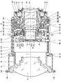
- FIG. 2 is a side sectional view showing a schematic configuration inside the interchangeable lens shown in FIG. 1.
- Side sectional view showing the configuration of the exterior body The figure which shows the attachment structure of an aperture ring and a rear cover Front view of base plate 11-11 sectional view of FIG.
- Block diagram showing the electrical configuration of the interchangeable lens Exploded view of interchangeable lens Sectional drawing which shows the 1st modification of the fixing structure of an exterior body. 15-15 sectional view of FIG.
- Sectional drawing which shows the 2nd modification of the fixing structure of an exterior body. 16-17 sectional view of FIG. Side view showing the external configuration of the interchangeable lens Sectional drawing which shows the 3rd modification of the fixing structure of an exterior body.
- the figure which shows the schematic structure of an opening / closing mechanism Side sectional view showing an example of an exterior body provided with two operation rings.
- FIG. 1 is a side view showing the external configuration of the interchangeable lens.
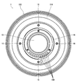
- FIG. 2 is a rear view of the interchangeable lens shown in FIG.
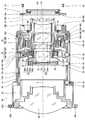
- FIG. 3 is a side sectional view showing a schematic configuration inside the interchangeable lens shown in FIG.
- the interchangeable lens 1 according to the present embodiment is a so-called zoom lens, and the focal length changes continuously by rotating the zoom ring 2 provided on the outer peripheral portion. Further, the interchangeable lens 1 of the present embodiment has a manual focus function, and the focus can be manually adjusted by rotating a focus ring 3 provided on an outer peripheral portion thereof. Further, the interchangeable lens 1 of the present embodiment has a function of setting an aperture value (F value), and the aperture value (F value) is manually set by rotating an aperture ring 4 provided on an outer peripheral portion thereof. Can be set.
- the zoom ring 2, the focus ring 3, and the aperture ring 4 are examples of a plurality of operation rings.
- the interchangeable lens 1 is mainly composed of a lens barrel main body 10 to which the lens is assembled, and an exterior body 100 that covers the outer circumference of the lens barrel main body 10.
- FIG. 4 is a side sectional view showing a schematic configuration of the lens barrel main body.
- the lens barrel main body 10 has a fixed barrel 12 and a cam barrel 14.
- the cam cylinder 14 is fitted to the inner peripheral part of the fixed cylinder 12 and holds the inner peripheral part of the fixed cylinder 12 so as to be rotatable in the circumferential direction.
- the fixed cylinder 12 has a mount 16 at the rear end (the end on the image surface side).
- the mount 16 is an example of a mount member, and is configured by a so-called bayonet mount.
- the mount 16 is attached to the rear end of the fixed cylinder 12 by a plurality of mounting screws 18.
- FIG. 5 is a diagram showing a mounting structure of the mount.
- the fixed cylinder 12 has mount fixing screw holes 12D at a plurality of positions on the end face at the rear end.
- the mount fixing screw holes 12D are arranged at regular intervals in the circumferential direction.
- the mount 16 has mount fixing holes 16C at a plurality of locations on the flange portion 16A.
- the mount fixing holes 16C are arranged at the same interval as the mount fixing screw holes 12D.
- the mount 16 is integrally attached to the rear end of the fixed cylinder 12 by passing the mount fixing screw 18 through the mount fixing hole 16C and screwing it into the mount fixing screw hole 12D.
- the fixed cylinder 12 is configured such that the rear end portion has the smallest outer diameter.
- the outer diameter of the mount 16 is equal to or less than the outer diameter of the rear end of the fixed cylinder 12. More specifically, the outer diameter of the flange portion 16A having the largest outer diameter is set to be equal to or less than the outer diameter of the rear end portion of the fixed cylinder 12. In the present embodiment, the outer diameter of the flange portion 16A is the same as the outer diameter of the rear end of the fixed cylinder 12.
- a plurality of lenses are arranged inside the fixed barrel 12. Specifically, a first lens group G1, a second lens group G2, a third lens group G3, a fourth lens group G4, and a fifth lens group G5 are arranged in order from the object side along the optical axis Z. .
- Each lens group includes at least one lens.
- ⁇ ⁇ Aperture St is arranged inside fixed cylinder 12.
- the stop St is disposed between the first lens group G1 and the second lens group G2.
- FIG. 6 is a diagram showing a moving state of each lens group when a zoom operation is performed.
- (A) shows the lens arrangement at the wide-angle end
- a (B) shows the lens arrangement at the telephoto end.
- the first lens group G1 to the fourth lens group G4 are lens groups that move with respect to the image plane Sim by a zoom operation.
- the fifth lens group G5 is a lens group fixed to the image plane Sim by a zoom operation.
- the first lens group G1 moves along a movement path AL1 by a zoom operation
- the second lens group G2 moves along a movement path AL2 by a zoom operation.
- the third lens group G3 moves along the movement path AL3 by the zoom operation
- the fourth lens group G4 moves along the movement path AL4 by the zoom operation.
- the stop St moves integrally with the second lens group G2.
- the third lens group G3 includes a front group G3a of the third lens group and a rear group G3b of the third lens group.
- the front group G3a of the third lens group is a lens group for correcting field curvature.
- the front group G3a of the third lens group is a lens group that can move independently of the other lens groups. When correcting the field curvature, the front group G3a of the third lens group is moved along the optical axis Z.
- the fourth lens group G4 is a lens group for focusing.
- the fourth lens group G4 is a lens group that can move independently of the other lens groups. When adjusting the focus, the fourth lens group G4 is moved along the optical axis Z.
- the first lens group holding frame 20 is provided with three first lens group driving cam pins 32 on the outer peripheral portion thereof.
- the three first lens group driving cam pins 32 are arranged at equal intervals in the circumferential direction.
- Each of the first lens group driving cam pins 32 is fitted into the first lens group driving cam groove 14A provided in the cam barrel 14 and the first lens group driving straight groove provided in the fixed barrel 12, respectively.
- the first lens group G1 is held in the fixed barrel 12.
- the cam barrel 14 is rotated, the first lens group G1 moves within the fixed barrel 12 along the optical axis Z.
- the second lens group G ⁇ b> 2 is held in the second lens group holding frame 22 and arranged in the fixed cylinder 12.
- the second lens group holding frame 22 is provided with three second lens group driving cam pins 34 on the outer peripheral portion thereof.
- the three second lens group driving cam pins 34 are arranged at equal intervals in the circumferential direction.
- the second lens group driving cam pins 34 are fitted in the second lens group driving cam grooves 14B provided in the cam barrel 14 and the second lens group driving straight grooves provided in the fixed barrel 12, respectively.
- the second lens group driving straight groove and the first lens group G1 driving straight groove are represented by the same groove.
- the second lens group G2 is held in the fixed barrel 12.
- the cam barrel 14 is rotated, the second lens group G2 moves along the optical axis Z in the fixed barrel 12.
- an aperture unit 30 constituting the aperture St is assembled to the second lens group holding frame 22.
- the stop St is disposed in the fixed barrel 12 and moves together with the second lens group G2.
- the third lens group G ⁇ b> 3 is held in the third lens group holding frame 24 and arranged in the fixed cylinder 12.
- the third lens group holding frame 24 includes a third lens group base holding frame 24A, a third lens group rear group holding frame 24B held on the inner periphery of the third lens group base holding frame 24A, and a third lens. And the third lens group front group holding frame 24C held on the inner periphery of the rear group holding frame 24B.
- the third lens group rear group holding frame 24B is movably held on the inner peripheral portion of the third lens group base holding frame 24A in a direction orthogonal to the optical axis Z.
- the third lens group front group holding frame 24C is held movably along the optical axis Z on the inner peripheral portion of the third lens group rear group holding frame 24B.
- the third lens group front group G3a is held by the third lens group front group holding frame 24C.
- the third lens group rear group G3b is held by the third lens group rear group holding frame 24B.
- FIG. 7 is a sectional view taken along the line 7-7 in FIG.
- the third lens group base holding frame 24A is provided with three third lens group driving cam pins 36 on its outer peripheral portion.
- the three third lens group driving cam pins 36 are arranged at equal intervals in the circumferential direction.
- the third lens group driving cam pins 36 are fitted into the third lens group driving cam grooves 14C provided in the cam barrel 14 and the third lens group driving straight grooves 12C provided in the fixed barrel 12, respectively. .
- the third lens group rear group holding frame 24B is provided with three holding pins 40 on the outer peripheral portion.
- the three holding pins 40 are arranged at equal intervals in the circumferential direction.
- Each holding pin 40 is fitted into a pin hole 42 provided in the third lens group base holding frame 24A.
- the pin hole 42 is formed by a long hole extending along the circumferential direction.
- the third lens group rear group holding frame 24B is movably held on the inner peripheral portion of the third lens group base holding frame 24A in a direction orthogonal to the optical axis Z.
- the third lens group rear group holding frame 24B is provided with two optical axis adjustment pins 44X and 44Y on the outer peripheral portion thereof.
- the two optical axis adjustment pins 44X and 44Y are arranged at 90 ° intervals in the circumferential direction.
- Each of the optical axis adjustment pins 44X and 44Y is slidably held in the radial direction with respect to the third lens group rear group holding frame 24B.
- Each of the optical axis adjustment pins 44X and 44Y is provided with a flange portion 44Xa and 44Ya at the tip.
- the optical axis adjustment pins 44X and 44Y are provided with screw portions 44Xb and 44Yb which can be rotated by a tool such as a Phillips screwdriver at the top.
- the screw portions 44Xb and 44Yb are screwed into screw holes 46X and 46Y provided in the third lens group base holding frame 24A, respectively.
- the third lens group rear group holding frame 24B is pushed and pulled with respect to the third lens group base holding frame 24A in a plane perpendicular to the optical axis Z. And its position is adjusted.
- the fixed barrel 12 and the cam barrel 14 are provided with through holes 12X, 12Y, 14X, 14Y corresponding to the positions of the optical axis adjusting pins 44X, 44Y, respectively. Thereby, each optical axis adjustment pin 44X, 44Y can be accessed via the through holes 12X, 12Y, 14X, 14Y.
- the through holes 12X, 12Y, 14X, and 14Y are covered with the exterior body 100 by attaching the exterior body 100 to the lens barrel main body 10. Therefore, the optical axis adjustment mechanism is first exposed when the exterior body 100 is removed from the lens barrel main body 10, and the adjustment can be performed.
- the holding mechanism between the third lens group base holding frame 24A and the third lens group rear group holding frame 24B is an example of an optical system adjusting mechanism.
- a main shaft 48 and a sub shaft 50 are provided on the inner peripheral portion of the third lens group rear group holding frame 24B.
- the main shaft 48 and the sub shaft 50 are arranged at positions facing each other across the optical axis Z (arranged at intervals of 180 ° in the circumferential direction), and are arranged along the optical axis Z, respectively.
- the third lens group front group holding frame 24C is slidably held by the main shaft 48 and the sub shaft 50 provided on the third lens group rear group holding frame 24B via the main guide portion 52 and the sub guide portion 54. .
- the third lens group front group holding frame 24C is movably held along the optical axis Z on the inner peripheral portion of the third lens group rear group holding frame 24B.
- the third lens group front group holding frame 24C is driven by the first motor 56 to move along the optical axis Z along the inner periphery of the third lens group rear group holding frame 24B.
- the first motor 56 is constituted by a moving magnet type voice coil motor.
- the plurality of magnets 56A and the plurality of inner yokes 56B of the voice coil motor constituting the first motor 56 are provided in the third lens group front group holding frame 24C.
- the third lens group rear group holding frame 24B is provided with a coil 56C of a voice coil motor constituting the first motor 56 and a plurality of outer yokes 56D.
- the third lens group G3 is held in the fixed barrel 12.
- the third lens group G3 moves along the optical axis Z in the fixed barrel 12 (the third lens group front group G3a and the third lens group rear group G3b are integrally formed). And moves within the fixed cylinder 12 along the optical axis Z.)
- the third lens group front group G3a moves alone along the optical axis Z (the third lens group front group G3a moves independently along the optical axis Z). .).
- the field curvature is corrected.
- the third lens group G3 moves in a plane perpendicular to the optical axis Z (the third lens group front group G3a and the third lens group rear group G3b They move together in a plane orthogonal to the optical axis Z.)
- the fourth lens group G4 is held in the fourth lens group holding frame 26 and arranged in the fixed cylinder 12.
- the fourth lens group holding frame 26 includes a fourth lens group base holding frame 26A, and a fourth lens group movable holding frame 26B held on the inner periphery of the fourth lens group base holding frame 26A.
- the fourth lens group movable holding frame 26B is movably held along the optical axis Z on the inner peripheral portion of the fourth lens group base holding frame 26A.
- the fourth lens group G4 is held on the inner periphery of the fourth lens group movable holding frame 26B.
- the fourth lens group base holding frame 26A is provided with three fourth lens group driving cam pins 38 on the outer peripheral portion thereof.
- the three fourth lens group driving cam pins 38 are arranged at equal intervals in the circumferential direction.
- the fourth lens group driving cam pins 38 are fitted into the fourth lens group driving cam grooves 14D provided in the cam barrel 14 and the fourth lens group driving straight grooves provided in the fixed barrel 12, respectively.
- the fourth lens group driving straight groove and the first lens group G1 driving straight groove are represented by the same groove.
- the fourth lens group base holding frame 26A is provided with a main shaft and a sub shaft (not shown) on its inner peripheral portion.
- the main axis and the sub axis are arranged along the optical axis Z.
- the fourth lens group movable holding frame 26B is slidably held on a main shaft and a sub shaft provided on the fourth lens group base holding frame 26A via a main guide portion and a sub guide portion (not shown).
- the fourth lens group movable holding frame 26B is movably held along the optical axis Z on the inner peripheral portion of the fourth lens group base holding frame 26A.
- the fourth lens group movable holding frame 26B is driven by the second motor 58 as a focus motor, and moves along the optical axis Z along the inner periphery of the fourth lens group base holding frame 26A.
- the second motor 58 is constituted by a moving coil type voice coil motor.
- the fourth lens group movable holding frame 26B is provided with a plurality of coils 58A of a voice coil motor constituting the second motor 58.
- the fourth lens group base holding frame 26A is provided with a plurality of magnets 58B, a plurality of inner yokes 58C, and a plurality of outer yokes 58D constituting the second motor 58.
- the fourth lens group G4 is held in the fixed barrel 12.
- the fourth lens group G4 moves along the optical axis Z in the fixed barrel 12.
- the fourth lens group G4 moves independently along the optical axis Z.
- the focus adjustment is performed by independently moving the fourth lens group G4.
- the fifth lens group G5 is held in the fifth lens group holding frame 28 and arranged in the fixed barrel 12.
- the fifth lens group holding frame 28 is attached to the fixed barrel 12 by a plurality of fifth lens group fixing screws 60.
- the lens barrel main body 10 is configured as described above.
- the first lens group G1, the second lens group G2, the third lens group G3, and the fourth lens group G4 move along the optical axis Z. Thereby, zooming is performed.
- the front group G3a of the third lens group moves independently along the optical axis Z.
- the interchangeable lens 1 corrects the curvature of field by independently moving the front group G3a of the third lens group.
- the fourth lens group G4 moves independently along the optical axis Z.
- the focus of the interchangeable lens 1 is adjusted by independently moving the fourth lens group G4.
- the third lens group G3 moves in a plane orthogonal to the optical axis by rotating the optical axis adjusting pins 44X and 44Y. Thereby, the adjustment of the optical axis Z is performed.
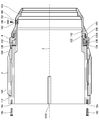
- FIG. 8 is a side sectional view showing the configuration of the exterior body.
- the exterior body 100 includes a cylindrical exterior body main body 110, and a focus ring 3, a zoom ring 2, and an aperture ring 4 attached to the outer periphery of the exterior body main body 110.
- the exterior body 110 is configured to be separable into a front exterior base 112 and a rear cover 114 on the rear side.
- the exterior body base 112 is an example of a first exterior body
- the rear cover 114 is an example of a second exterior body.
- the focus ring 3, the zoom ring 2, and the aperture ring 4 are provided on an outer peripheral portion of the exterior base 112.
- the exterior body base 112 includes a first exterior body base 112A and a second exterior body base 112B. Both the first exterior base 112A and the second exterior base 112B have a cylindrical shape, and are integrated by joining the front end of the second exterior base 112B to the rear end of the first exterior base 112A. Thus, the exterior body base 112 is configured.
- the focus ring 3 and the spacer 116 are fitted around the outer periphery of the first exterior body base 112A.
- the zoom ring 2 is fitted on the front side of the outer peripheral portion of the second exterior body base 112B, and the aperture ring 4 is fitted on the rear side.
- the first exterior base 112A and the second exterior body are inserted.
- the focus ring 3 and the zoom ring 2 are assembled to the exterior body base 112.
- the focus ring 3 and the zoom ring 2 assembled to the exterior body base 112 are rotatably supported in a state in which movement in the optical axis direction is restricted.
- the mounting portion of the aperture ring 4 has a bayonet structure.
- the aperture ring 4 is an operation ring arranged at the rear end, and is attached to the second exterior body base 112B by a bayonet structure.
- FIG. 9 is a diagram showing a mounting structure of the aperture ring and the rear cover.
- the outer peripheral surface of the second exterior body base 112B is provided with an aperture ring holding groove 120 constituting a bayonet structure.
- the inner peripheral portion of the aperture ring 4 is provided with an aperture ring holding claw 122 constituting a bayonet structure.
- the aperture ring holding groove 120 is composed of a vertical groove 120A extending along the optical axis direction and a horizontal groove 120B extending along the circumferential direction.
- the vertical groove 120A is connected to the horizontal groove 120B at the front end, and the rear end is opened at the rear end surface of the second exterior base 112B.
- the opening is configured as an inlet 120C of the aperture ring holding groove 120.
- the lateral groove 120B has a length corresponding to the range of the rotation operation of the aperture ring 4.
- the drawing ring holding claw 122 is provided as a rectangular projection protruding from the inner peripheral portion of the drawing ring 4.
- the lateral width (width in the circumferential direction) of the aperture ring holding claw 122 has a length corresponding to the width (width in the circumferential direction) of the vertical groove 120A, and the vertical width (width in the optical axis direction) of the aperture ring holding claw 122.
- the height of the drawing ring holding claw 122 has the same length as the depth of the drawing ring holding groove 120.
- the aperture ring 4 When the aperture ring 4 is mounted on the second exterior body base 112B, first, the position of the aperture ring holding claw 122 is adjusted to the position of the entrance portion 120C of the aperture ring holding groove 120, and the aperture ring holding claw 122 is inserted into the vertical groove 120A. Fit. Thereafter, the aperture ring 4 is slid forward along the optical axis, and when the front end of the aperture ring 4 contacts the second exterior body base 112B, the aperture ring 4 is rotated in the circumferential direction. Thus, the aperture ring holding claw 122 enters the lateral groove 120B. When the aperture ring holding claw 122 enters the lateral groove 120B, the movement of the aperture ring 4 in the optical axis direction is restricted, and the aperture ring 4 is held on the outer peripheral portion of the second exterior body base 112B.
- the aperture ring 4 is provided with a click mechanism, and is urged in the optical axis direction by using the urging force of a spring constituting the click mechanism.
- the aperture ring holding claw 122 is pressed against the inner wall surface of the lateral groove 120B, and the aperture ring 4 is stably held against the second exterior base 112B. Will be held.
- the click mechanism includes a ring-shaped base plate 130 provided on the second exterior body base 112B, a ring-shaped rotary wheel 132 provided on the aperture ring 4, a click ball 134 provided on the rotary wheel 132, and a click ball 134. And a ball urging spring 136 for urging the ball.
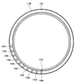
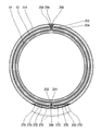
- FIG. 10 is a front view of the base plate.
- the base plate 130 is fixedly attached to the second exterior body base 112B.
- the base plate 130 has a plurality of recesses 130A on its end surface.
- Each of the recesses 130A has a hemispherical shape into which the click ball 134 can be fitted, and is arranged at regular intervals in the circumferential direction.
- the rotating wheel 132 is fixedly attached to the inner peripheral portion of the aperture ring 4. Therefore, when the aperture ring 4 is attached to the second exterior body base 112B, the aperture ring 4 rotates together with the aperture ring 4.
- the rotating wheel 132 is provided with a recess 132A in which a click ball 134 and a ball urging spring 136 are accommodated.
- the recess 132A is formed by a hole extending along the optical axis direction.
- the click ball 134 and the ball urging spring 136 are housed in the recess 132A and provided so as to be able to protrude and retract from the opening of the recess 132A.
- the click ball 134 is pressed against the end face of the base plate 130 by the urging force of the ball urging spring 136. Is done.
- the click ball 134 fits into the concave portion 130A provided in the base plate 130 at a predetermined position.
- the aperture ring 4 is held at a fixed position.
- the aperture ring 4 is mounted on the second exterior body base 112B, the aperture ring 4 is moved by the urging force of the ball urging spring 136 to cause the second exterior body base 112B. Is stably held.
- the ball urging spring 136 is an example of an urging member.
- the rear cover 114 has a shape whose diameter gradually decreases toward the rear end.
- the rear end of the rear cover 114 has an inner diameter corresponding to the outer diameter of the rear end of the lens barrel body 10.
- the flange 16 ⁇ / b> A of the mount 16 fits on the inner peripheral portion of the rear end of the rear cover 114.
- the connecting portion between the rear cover 114 and the second exterior base 112B has a bayonet structure.
- the rear cover 114 is attached to the second exterior base 112B by a bayonet structure.
- a rear cover holding groove 140 forming a bayonet structure is provided on the outer peripheral surface of the second exterior body base 112B.
- a rear cover holding claw 142 constituting a bayonet structure is provided on the inner peripheral portion of the rear cover 114.
- the rear cover holding groove 140 is composed of a vertical groove 120A extending along the optical axis direction and a horizontal groove 140B extending along the circumferential direction.
- the vertical groove 120 ⁇ / b> A is shared with the vertical groove of the bayonet structure in the aperture ring 4.
- the rear cover holding claws 142 are provided as rectangular projections protruding from the inner peripheral portion of the rear cover 114.
- the lateral width (width in the circumferential direction) of the rear cover holding claw 142 has a length corresponding to the width (width in the circumferential direction) of the vertical groove 120A
- the vertical width (width in the optical axis direction) of the rear cover holding claw 142 is It has a length corresponding to the width (width in the optical axis direction) of the lateral groove 140B.
- the height of the rear cover holding claw 142 has the same length as the depth of the aperture ring holding groove 120.
- the rear cover holding claw 142 When attaching the rear cover 114 to the second exterior body base 112B, first, the position of the rear cover holding claw 142 is aligned with the position of the entrance 120C of the rear cover holding groove 140, and the rear cover holding claw 142 is fitted into the vertical groove 120A. Thereafter, the rear cover 114 is slid forward along the optical axis, and when the front end of the rear cover 114 contacts the second exterior base 112B, the rear cover 114 is rotated in the circumferential direction. As a result, the rear cover holding claws 142 enter the lateral grooves 140B. When the rear cover holding claw 142 enters the lateral groove 140B, the movement of the rear cover 114 in the optical axis direction is restricted, and the rear cover 114 is held on the outer peripheral portion of the second exterior base 112B.
- the exterior body 100 is mounted on the lens barrel main body 10 after assembling the focus ring 3, the zoom ring 2, and the aperture ring 4 with the exterior body body 110 and integrating them.
- the mounting of the exterior body 100 is performed by sliding the exterior body 100 along the optical axis from the rear side of the lens barrel main body 10.
- the flange 16A of the mount 16 has the same outer diameter as the outer diameter of the rear end of the outer housing 100, the outer housing 100 can be detached while being attached to the lens barrel main body 10.
- the lens barrel main body 10 has a flange portion 12 ⁇ / b> A at a distal end (an end on the object side) of the fixed barrel 12.
- the exterior body 100 is positioned in the optical axis direction by the tip of the exterior body base 112 abutting on the flange portion 12A.
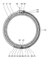
- FIG. 11 is a sectional view taken along line 11-11 of FIG.
- the lens barrel main body 10 has a plurality of positioning recesses 12 ⁇ / b> B on the outer periphery of the fixed barrel 12.
- Each positioning recess 12B is formed by a groove having an arcuate cross section extending along the optical axis Z, and is arranged at regular intervals in the circumferential direction.
- the exterior body 100 has a plurality of positioning projections 112C on the inner periphery of the exterior body base 112 (the inner periphery of the first exterior body base 112A).
- Each positioning projection 112C is formed of a streaky projection extending along the optical axis.
- Each positioning projection 112C has a cross-sectional shape corresponding to the positioning recess 12B, and is arranged at the same interval as the positioning recess 12B.
- the positioning convex portion 112C is fitted into the positioning concave portion 12B and then mounted. Thereby, the exterior body 100 is positioned in the circumferential direction.
- the exterior body 100 attached to the lens barrel main body 10 is fixed to the exterior body main body 110 using the exterior body base fixing screw 150 and the rear cover fixing screw 152.
- the exterior body 100 has exterior body base fixing screw holes 154 along the optical axis Z at a plurality of positions on the distal end surface of the exterior base 112 (the distal end surface of the first exterior base 112A).
- the outer body base fixing screw holes 154 are provided at regular intervals in the circumferential direction (see FIG. 11).
- the lens barrel main body 10 has exterior body fixing holes 156 at a plurality of locations of the flange portion 12A provided at the distal end of the fixing cylinder 12.
- the outer body fixing holes 156 are arranged at the same intervals as the outer body base fixing screw holes 154.
- the exterior body 100 is fixed to the lens barrel main body 10 by passing the exterior body base fixing screw 150 through the exterior body fixing hole 156 and screwing it into the exterior body base fixing screw hole 154. More specifically, exterior body base 112 constituting exterior body 100 is fixed to fixed barrel 12 of lens barrel main body 10.
- the rear cover 114 has a recess 160 on its outer peripheral surface.
- the concave portion 160 is an example of a first concave portion and a second concave portion, and a rear cover fixing hole 162 is provided on a bottom surface thereof.
- the rear cover fixing hole 162 is formed by a through hole, and is provided orthogonal to the optical axis Z.
- the lens barrel main body 10 has a rear cover fixing screw hole 164 on the outer peripheral portion of the fixing cylinder 12.
- the rear cover fixing screw hole 164 is provided orthogonal to the optical axis Z.
- the rear cover fixing hole 162 and the rear cover fixing screw hole 164 are arranged coaxially when the exterior body 100 is positioned and mounted on the lens barrel main body 10.
- the exterior body 100 is fixed to the fixing cylinder 12 by passing the rear cover fixing screw 152 through the rear cover fixing hole 162 and screwing it into the rear cover fixing screw hole 164.
- the rear cover fixing screw 152 to which the rear cover 114 is fixed is housed in the recess 160.
- the rear cover fixing screw 152 is an example of a first fastening member and a second fastening member.
- the decorative plate 166 is formed of a plate piece that can be fitted into the opening of the recess 160.
- the decorative plate 166 is attached to the rear cover 114 with an adhesive.
- the decorative board 166 is an example of a first decorative member and a second decorative member.
- the decorative plate 166 is used, for example, as a nameplate.
- connecting members 170 are attached to a plurality of positions of the zoom ring 2, and the zoom ring 2 and the cam barrel 14 are connected by the connecting members 170.
- the zoom ring 2 is composed of a zoom ring main body 2A and a cylindrical zoom ring cover 2B mounted on the outer periphery of the zoom ring main body 2A.
- the zoom ring main body 2A has a cylindrical shape, and has a cover mounting groove 2a for mounting the zoom ring cover 2B on an outer peripheral portion thereof.
- the cover mounting groove 2a is provided with a plurality of connecting member mounting portions 172.
- Each connecting member mounting portion 172 is formed of a concave portion, and is arranged at regular intervals in the circumferential direction.
- the zoom ring cover 2B has a cylindrical shape and is made of an elastic material such as rubber.
- the zoom ring cover 2B is mounted on the zoom ring main body 2A by being fitted into the cover mounting groove 2a.
- the connecting member 170 is formed of a plate-like piece bent in an L-shape, and has a mounting portion 170A for mounting to the zoom ring main body 2A and a connecting portion 170B for connecting to the cam barrel 14.
- the connecting member 170 is attached to the zoom ring main body 2A by fixing the mounting portion 170A to the zoom ring main body 2A with the connecting member fixing screw 174.
- the connecting member 170B of the connecting member 170 attached to the zoom ring main body 2A is disposed orthogonal to the optical axis Z.
- the fixed barrel 12 is provided with a slit 176 for passing the connecting portion 170B of the connecting member 170 attached to the zoom ring 2.
- the slit 176 has a length corresponding to the movable range of the zoom ring 2, and is arranged along the circumferential direction.
- the cam cylinder 14 is provided with a fitting portion 178 into which the tip of the connecting portion 170B fits.
- the connecting member 170 attached to the zoom ring main body 2A has a front end portion of the connecting portion 170B fitted into the fitting portion 178. Thereby, the connecting member 170 is connected to the cam cylinder 14.
- the zoom ring 2 and the cam barrel 14 are connected.
- the zoom ring cover 2B is attached to the zoom ring main body 2A after attaching the connecting member 170 to the zoom ring main body 2A.
- the connecting member 170 is covered and hidden by the zoom ring cover 2B.
- FIG. 12 is a block diagram illustrating an electrical configuration of the interchangeable lens.
- the interchangeable lens 1 includes a third lens group front group drive section 210 that drives the third lens group front group G3a, a third lens group front group position detection section 212 that detects the position of the third lens group front group G3a, and a fourth The fourth lens group driving unit 214 for driving the lens group G4, the fourth lens group position detecting unit 216 for detecting the position of the fourth lens group G4, the diaphragm driving unit 218 for driving the diaphragm St, and the temperature in the interchangeable lens 1
- a temperature control unit 220 for detecting a focus operation, a focus operation detection unit 222 for detecting a focus operation, a zoom setting detection unit 224 for detecting a zoom operation, an aperture setting detection unit 226 for detecting an aperture operation, and overall control of the entire operation of the interchangeable lens 1.
- a lens control unit 228 that performs the operation.
- the third lens group front group drive section 210 includes the first motor 56 and its drive circuit.
- the third lens group front group drive section 210 drives the first motor 56 in response to a command from the lens control section 228 to move the third lens group front group G3a along the optical axis Z.
- the third lens group front group position detection unit 212 includes a position detection sensor (not shown).
- the position detection sensor is configured by a magnetic sensor such as a Hall element or a magneto-resistive element (Magneto-Resistive-Sensor).
- the third lens group front group position detection unit 212 detects the position of the third lens group front group G3a with a position detection sensor, and outputs the detection result to the lens control unit 228.
- the position of the third lens group front group G3a is a position with respect to the third lens group rear group G3b, and is a position in the third lens group rear group holding frame 24B.
- the fourth lens group driving unit 214 includes the second motor 58 and a driving circuit thereof.
- the fourth lens group drive unit 214 drives the second motor 58 in response to a command from the lens control unit 228 to move the fourth lens group G4 along the optical axis Z.
- the fourth lens group position detecting section 216 includes a position detecting sensor (not shown).
- the position detection sensor is composed of, for example, a magnetic sensor such as a Hall element or a magnetoresistive element.
- the fourth lens group position detector 216 detects the position of the fourth lens group G4 with a position sensor, and outputs the detection result to the lens controller 228.
- the position of the fourth lens group G4 is a position in the fourth lens group holding frame 26.
- the aperture drive unit 218 includes an aperture motor and a drive circuit therefor.
- An aperture motor (not shown) is provided in the aperture unit 30.
- the aperture driving unit 218 drives an aperture motor in response to a command from the lens control unit 228 to open and close the aperture St.
- the temperature detection unit 220 includes a temperature sensor (not shown).
- the temperature sensor is provided in the aperture unit 30, for example.
- Temperature detecting section 220 detects the temperature in interchangeable lens 1 with a temperature sensor, and outputs the detection result to lens control section 228.
- the focus operation detection unit 222 detects the amount of rotation operation of the focus ring 3 and outputs the detection result to the lens control unit 228.
- the lens control unit 228 detects a focus operation amount based on an output from the focus operation detection unit 222.
- the zoom setting detection unit 224 detects the setting position of the zoom ring 2 and outputs the detection result to the lens control unit 228.
- the lens control unit 228 detects a zoom set value (focal length) based on the output from the zoom setting detection unit 224.
- the aperture setting detector 226 detects the set position of the aperture ring 4 and outputs the detection result to the lens controller 228.
- the lens control unit 228 detects a set value of the aperture (aperture value) based on an output from the aperture setting detection unit 226.
- the lens control unit 228 controls the operation of each unit based on the operation of the focus ring 3, the zoom ring 2, and the aperture ring 4. Specifically, when the manual focus is set, the fourth lens group drive unit 214 is driven based on the rotation amount of the focus ring 3 to move the fourth lens group G4. Further, based on the setting of the zoom ring 2, the third lens group front group driving section 210 and the fourth lens group driving section 214 are driven to move the third lens group front group G3a and the fourth lens group G4 to predetermined positions. Let it. Further, based on the setting of the aperture ring 4, the aperture driving unit 218 is driven to set the aperture St to a predetermined aperture (aperture value).
- the lens control unit 228 controls the operation of each unit according to a command from the camera on which the interchangeable lens 1 is mounted.
- the fourth lens group driving unit 214 is driven based on autofocus information from the camera to move the fourth lens group G4 to a predetermined position.
- the aperture driving unit 218 is driven based on the aperture setting information from the camera, and the aperture St is set to a predetermined opening amount.
- the lens control unit 228 communicates with the camera control unit 230 of the camera, and receives a drive command for each unit from the camera control unit 230.
- the camera control unit 230 transmits zoom setting information, aperture setting information, focus position information, and the like. Communication between the lens control unit 228 and the camera control unit 230 is performed via a terminal 16 ⁇ / b> B provided on the mount 16.
- the lens control section 228 drives the third lens group front group drive section 210 based on the temperature detected by the temperature detection section 220 to move the third lens group front group G3a to a predetermined position.
- the lens control unit 228 is configured by, for example, a computer having a CPU (Central Processing Unit), a ROM (Read Only Memory), and a RAM (Random Access Memory), and by executing a predetermined program. And implement various control functions.
- a computer having a CPU (Central Processing Unit), a ROM (Read Only Memory), and a RAM (Random Access Memory), and by executing a predetermined program. And implement various control functions.
- a CPU Central Processing Unit
- ROM Read Only Memory
- RAM Random Access Memory
- FIG. 13 is an exploded view of the interchangeable lens.
- the assembly of the interchangeable lens 1 is performed in the following procedure.
- a lens or the like is attached to the lens barrel main body 10.
- the mount 16 is attached to the lens barrel main body 10 on which the lens and the like are assembled.
- the mount 16 is attached to the fixed cylinder 12 using mount fixing screws 18.
- the optical axis Z is adjusted. That is, since the adjustment mechanism of the optical axis Z is exposed by removing the exterior body 100, the optical axis Z is adjusted before the exterior body 100 is attached.
- the adjustment of the optical axis Z is performed by setting the lens barrel main body 10 on a predetermined inspection device. That is, the inspection is performed by inspecting the state of the optical axis Z by the inspection device and adjusting the position of the third lens group G3 based on the inspection result.
- the position of the third lens group G3 is adjusted by the optical axis adjustment pins 44X and 44Y. That is, the rotation is performed by rotating the optical axis adjustment pins 44X and 44Y using a tool.
- the adjustment of the optical axis Z is performed with the mount 16 attached.
- the exterior body 100 is mounted on the lens barrel main body 10.
- the exterior body 100 has the focus ring 3, the zoom ring 2, and the aperture ring 4 assembled to the exterior body 110 in advance.
- the zoom ring 2 is assembled with the zoom ring cover 2B removed.
- the outer body 100 is mounted from the rear end side of the lens barrel main body 10. That is, the lens barrel body 10 is mounted by sliding along the optical axis Z from the rear end side. At this time, the positioning is performed so that the positioning protrusion 112C is fitted into the positioning recess 12B. Thereby, the exterior body 100 is positioned and attached to the lens barrel main body 10.
- the entire outer periphery of the lens barrel main body 10 is covered with the exterior body 100.
- the flange portion 16B of the mount 16 is fitted to the inner peripheral portion of the rear end of the exterior body 100 (the inner peripheral portion of the rear end of the rear cover 114).
- the exterior body main body 110 is fixed to the lens barrel main body 10 using the exterior body base fixing screw 150 and the rear cover fixing screw 152.
- the exterior body base fixing screw 150 is passed through the exterior body fixing hole 156 and screwed into the exterior body base fixing screw hole 154 to fix the exterior body base 112 to the fixing cylinder 12.
- the rear cover fixing screw 152 is passed through the rear cover fixing hole 162 and screwed into the rear cover fixing screw hole 164 to fix the rear cover 114 to the fixing cylinder 12.
- the exterior body 100 is fixed to the lens barrel main body 10.
- the rear cover 114 temporarily fixed by the bayonet structure is fixed inseparably.
- the aperture ring 4 temporarily fixed by the bayonet structure is also attached inseparably.
- the rear cover fixing screw 152 to which the exterior body 100 is fixed is housed in the recess 160.
- a decorative plate 166 is attached to the concave portion 160 to cover the opening.
- the rear cover fixing screw 152 is covered and covered by the decorative plate 166.
- the decorative plate 166 is attached to the recess 160 with an adhesive.
- the connecting member 170 is attached to the zoom ring main body 2A, and the zoom ring main body 2A and the cam barrel 14 are connected. As a result, the cam barrel 14 rotates in conjunction with the zoom ring 2.
- the interchangeable lens 1 is assembled through the above series of steps.
- the optical axis can be adjusted while the mount 16 is mounted, and even after the optical axis is adjusted, the exterior body 100 can be mounted with the mount 16 mounted.
- the exterior body 100 can be easily assembled because only an integral body is attached to the lens barrel main body 10.
- assembling of the exterior body 100 can be performed in a step different from that of assembling the lens barrel main body 10, so that the entire assembling work can be made more efficient.
- the procedure is reverse to that of the assembly. That is, first, the zoom ring cover 2B is removed, and the connecting member 170 is removed. Thereby, the connection between the zoom ring main body 2A and the cam barrel 14 is released.
- the decorative plate 166 is removed, and the screw 152 for fixing the rear cover is removed.
- the fixing screws 150 for fixing the exterior body base are removed. Thereby, the connection between the lens barrel main body 10 and the exterior body 100 is released. In this state, the exterior body 100 is slid rearward (on the mount 16 side) along the optical axis Z. Thereby, the exterior body 100 is removed.
- the exterior body 100 can be detached while the mount 16 is attached to the lens barrel main body 10.
- optical adjustment or the like can be performed with the mount 16 attached.
- FIG. 14 is a cross-sectional view illustrating a first modification of the fixing structure of the exterior body.
- FIG. 15 is a sectional view taken along line 15-15 of FIG.
- the rear cover 114 is fixed at two places. For this reason, the rear cover 114 of the present example is provided with a first fixing portion and a second fixing portion.
- the rear cover 114 has a first recess 240 on the outer peripheral surface.
- a first rear cover fixing hole 242 is provided on the bottom surface of the first recess 240.
- the first rear cover fixing hole 242 is formed as a through hole, and is provided orthogonal to the optical axis Z.
- the lens barrel main body 10 has a first rear cover fixing screw hole 244 on the outer peripheral portion of the fixing cylinder 12.
- the first rear cover fixing screw hole 244 is provided orthogonal to the optical axis Z.
- the first rear cover fixing hole 242 and the first rear cover fixing screw hole 244 are arranged coaxially when the exterior body 100 is positioned and mounted on the lens barrel main body 10.
- the rear cover 114 is fixed to the fixed cylinder 12 by passing the first rear cover fixing screw 246 through the first rear cover fixing hole 242 and screwing it into the first rear cover fixing screw hole 244.
- the first rear cover fixing screw 246 to which the rear cover 114 is fixed is housed in the first recess 240.
- the first rear cover fixing screw 246 is an example of a first fastening member.
- the decorative plate 248 is formed of a plate piece that can be fitted into the opening of the first recess 240.
- the first decorative plate 248 is attached to the rear cover 114 with an adhesive.
- the first decorative plate 248 is an example of a first decorative member.
- the rear cover 114 has a second recess 250 on the outer peripheral surface thereof.
- the second fixing part is provided at a position rotated by 180 ° in the circumferential direction from the first fixing part. Therefore, the first fixing portion and the second fixing portion are arranged at positions facing each other with the optical axis Z interposed therebetween.
- a second rear cover fixing hole 252 is provided on the bottom surface of the second recess 250.
- the second rear cover fixing hole 252 is formed by a through hole, and is provided orthogonal to the optical axis Z.
- the lens barrel main body 10 has a second rear cover fixing screw hole 254 on the outer peripheral portion of the fixing cylinder 12.
- the second rear cover fixing screw hole 254 is provided orthogonal to the optical axis Z.
- the second rear cover fixing hole 252 and the second rear cover fixing screw hole 254 are arranged coaxially when the exterior body 100 is positioned and mounted on the lens barrel main body 10.
- the rear cover 114 is fixed to the fixed cylinder 12 by passing the second rear cover fixing screw 256 through the second rear cover fixing hole 252 and screwing it into the second rear cover fixing screw hole 254.
- the second rear cover fixing screw 256 to which the rear cover 114 is fixed is housed in the second recess 250.
- the second rear cover fixing screw 256 is an example of a second fastening member.
- the decorative plate 258 is configured by a plate piece that can be fitted into the opening of the second recess 250.
- the second decorative plate 258 is attached to the rear cover 114 with an adhesive.
- the second decorative plate 258 is an example of a second decorative member.
- the interchangeable lens 1 of this example since the rear cover 114 is fixed at two places, the exterior body 100 can be more firmly fixed. Further, since the two fixing portions are arranged at symmetrical positions with respect to the optical axis Z, the fixing portions can be stably fixed.
- FIG. 16 is a cross-sectional view illustrating a second modification of the fixing structure of the exterior body.
- FIG. 17 is a sectional view taken along line 17-17 of FIG.
- FIG. 18 is a side view showing the external configuration of the interchangeable lens.
- the interchangeable lens of this example also fixes the rear cover 114 at two places.
- the rear cover 114 has a duct portion, and the duct portion has the first fixing portion. Since the configuration of the second fixing portion is the same as that of the first modification, the configuration of the first fixing portion will be described here.
- the duct portion is provided on the rear cover 114, and the first fixing portion is provided on the duct portion.
- the duct section provides a function of supplying and exhausting air in the interchangeable lens. By supplying and exhausting the air in the interchangeable lens with this duct portion, it is possible to reduce the resistance when the lens is moved by a zoom operation or the like.
- the rear cover 114 has a duct recess 260 on the outer peripheral surface thereof.
- the duct recess 260 is an example of a first recess.
- the concave portion 260 for the duct is provided with a first rear cover fixing hole 242 at the center of the bottom surface.
- the first rear cover fixing hole 242 is formed as a through hole, and is provided orthogonal to the optical axis Z.
- the lens barrel main body 10 has a first rear cover fixing screw hole 244 on the outer peripheral portion of the fixing cylinder 12.
- the first rear cover fixing screw hole 244 is provided orthogonal to the optical axis Z.
- the first rear cover fixing hole 242 and the first rear cover fixing screw hole 244 are arranged coaxially when the exterior body 100 is positioned and mounted on the lens barrel main body 10.
- the rear cover 114 is fixed to the fixed cylinder 12 by passing the first rear cover fixing screw 246 through the first rear cover fixing hole 242 and screwing it into the first rear cover fixing screw hole 244.
- the first rear cover fixing screw 246 to which the rear cover 114 is fixed is housed in the duct recess 260.
- the first rear cover fixing screw 246 is an example of a first fastening member.
- a pair of ventilation holes 270 are provided on the bottom surface of the concave portion 260 for the duct with the first rear cover fixing hole 242 interposed therebetween.
- the ventilation port 270 is formed by a through hole, and is provided with a filter 272.
- the vent 270 is an example of a vent. The air inside the interchangeable lens is supplied and exhausted through the vent 270.
- a duct cover 274 is attached to the duct recess 260.
- the duct cover 274 is an example of a first decorative member.
- the duct cover 274 is detachably attached to the rear cover 114 by a duct cover fixing screw 276.
- the duct cover 274 attached to the duct recess 260 closes the opening of the duct recess 260 in a permeable state. Thereby, ventilation of the ventilation port 270 is ensured.
- the first rear cover fixing screw 246 and the ventilation hole 270 to which the rear cover 114 is fixed are covered and hidden by the duct cover 274 when the duct cover 274 is attached to the rear cover 114.
- the provision of the duct portion can reduce the resistance when the lens is moved. Further, the configuration can be simplified by also using the duct portion and the fixing portion of the rear cover 114.
- FIG. 19 is a cross-sectional view illustrating a third modification of the fixing structure of the exterior body.
- the second decorative plate 258 is integrally provided on the rear cover 114 so as to be openable and closable. Further, a mechanism for opening and closing the second decorative plate 258 is provided. Hereinafter, the opening and closing mechanism of the second decorative plate 258 will be described.
- FIG. 20 is a diagram showing a schematic configuration of the opening / closing mechanism.
- the second decorative plate 258 has a shaft portion 258A, and the shaft portion 258A is rotatably supported by the rear cover 114.
- the second decorative plate 258 opens and closes the opening of the second recess 250 by swinging about the shaft 258A as a fulcrum.
- a lock claw 258B is provided on the back surface of the second decorative plate 258 (the surface located on the inner diameter side when the second decorative plate 258 is closed).
- a lock pin 280 is provided in the second recess 250.
- the lock pin 280 is provided to be able to protrude and retract from a pin hole 282 provided on the inner wall surface of the second recess 250.
- a pin urging spring 284 is built in the pin hole 282.
- the pin urging spring 284 urges the lock pin 280 in a protruding direction.
- a lock release wire 286 is connected to the lock pin 280.
- the lock release wire 286 is arranged along a wire passage 288 provided in the rear cover 114.
- the wire passage 288 is configured as a passage connecting the duct concave portion 260 and the second concave portion 250, and is arranged along the circumferential direction of the rear cover 114.
- the other end of the lock release wire 286 is connected to a lock release knob 290 provided in the recess 260 for the duct.
- the lock release knob 290 is an example of a lock release operation member.
- the lock release knob 290 has a ring shape, is arranged coaxially with the first rear cover fixing hole 242, and is rotatably held in the duct concave portion 260.
- the lock release knob 290 has a minus-shaped groove 290A at the top, and is configured to be rotatable with a tool such as a minus driver using the groove 290A.
- the lock release knob 290 and the lock release wire 286 are examples of a lock release mechanism that releases the lock of the second decorative plate 258.
- removal of the exterior body 100 is performed in the following procedure.
- the second decorative plate 258 is integrally provided on the rear cover 114 so as to be openable and closable. Accordingly, it is not necessary to replace the second decorative plate 258 every time the disassembly is performed, so that economical operation is possible. In addition, loss can be prevented. Further, since a member (an unlocking knob 290) for unlocking the second decorative plate 258 is provided in the concave portion 260 for the duct, it is possible to prevent the second decorative plate 258 from being opened carelessly.
- the second decorative plate 258 is configured to be locked by the lock mechanism, but the second decorative plate 258 may be configured to be fixed by screws or the like.
- the second decorative plate 258 may be configured to be urged in an opening direction by an urging means such as a spring and to be automatically opened when the lock is released.
- FIG. 21 is a side sectional view showing an example of an exterior body provided with two operation rings.
- This figure shows an example of the exterior of the single focus lens.
- the exterior body 110 is provided with the focus ring 3 and the aperture ring 4.
- the exterior body base 112 constituting the exterior body main body 110 can be constituted by one part.
- the combination of the operation rings provided on the exterior body 100 is appropriately set according to the functions provided on the interchangeable lens 1.
- a single focus lens is provided with a focus ring and an aperture ring.
- the zoom lens may include only a zoom ring and a focus ring.
- the aperture is set on the camera side.
- the zoom lens may include only a zoom ring and an aperture ring.
- only the auto focus is set.
- the zoom lens may include only a focus ring and an aperture ring. In this case, the movement of the lens by zoom is performed by a motor, and the zoom operation is performed by the camera.
- the mount is configured by a bayonet mount, but the type of mount is not limited to this.
- a mount suitable for the optical device to be mounted is adopted.
- a screw type mount, a spigot type mount, or the like can be adopted.
- the present invention when the present invention is applied to an interchangeable lens of an interchangeable lens camera, the type of camera is not particularly limited. In addition to so-called still cameras such as digital cameras and silver halide cameras, the present invention can be similarly applied to interchangeable lenses used for video cameras, television cameras, cine cameras and the like.
Landscapes
- Physics & Mathematics (AREA)
- General Physics & Mathematics (AREA)
- Optics & Photonics (AREA)
- Structure And Mechanism Of Cameras (AREA)
- Lens Barrels (AREA)
- Cameras Adapted For Combination With Other Photographic Or Optical Apparatuses (AREA)
Abstract
分解及び組み立てが容易な交換レンズを提供する。交換レンズ(1)は、光学系が取り付けられた鏡胴本体(10)と、鏡胴本体(10)の後端部に取り付けられるマウント(16)と、鏡胴本体(10)に装着されて鏡胴本体(10)の外周を覆う外装体(100)と、外装体(100)の外周部に備えられる複数の操作リング(2、3、4)と、を備える。外装体(100)は、ねじ(150、152)で鏡胴本体(10)に固定される。外装体(100)を取り外す場合は、ねじ(150、152)を外し、外装体(100)を光軸に沿って後方にスライドさせる。これにより、マウント(16)を鏡胴本体(10)に取り付けたまま、外装体(100)を取り外すことができる。
Description
本発明は、交換レンズに係り、特に分解可能な交換レンズに関する。
レンズ交換式の光学機器において、交換レンズはマウントを介してボディーに接続される。交換レンズのマウントは、通常、鏡胴とは別部品で構成され、ねじを利用して、鏡胴に取り付けられる。
従来の交換レンズは、マウントが、交換レンズの外装体と共締めされて、鏡胴に取り付けられる構造とされていた(たとえば、特許文献1等参照)。したがって、メンテナンス等で交換レンズを分解する場合は、必ずマウントも取り外される構造とされていた。
しかしながら、マウントが取り外されると、再度組み立てる際に、新たに位置調整を行ってマウントを取り付ける必要があり、組み立てに手間がかかるという欠点があった。また、マウントの脱着によって、レンズの倒れ等が生じ、光学性能が低下するおそれもあった。
本発明は、このような事情に鑑みてなされたもので、分解及び組み立てが容易な交換レンズを提供することを目的とする。
上記課題を解決するための手段は、次のとおりである。
(1)光学系が取り付けられた鏡胴本体と、鏡胴本体の後端部に取り付けられるマウント部材と、鏡胴本体に装着されて鏡胴本体の外周を覆う、外周部に複数の操作リングを備える外装体であって、光軸の方向に沿ってスライドさせることにより、マウント部材が取り付けられた状態の鏡胴本体に対して脱着が可能な外装体と、外装体を鏡胴本体に固定する第1締結部材と、を備えた交換レンズ。
本態様によれば、外装体を光軸の方向に沿ってスライドさせることにより、マウント部材を鏡胴本体に取り付けたまま、外装体を鏡胴本体から取り外すことができる。これにより、マウント部材を取り付けたまま、鏡胴本体を取り出すことができる。また、マウント部材を取り付けたまま、鏡胴本体に対して、光学調整等を行うことができる。更に、分解して再度組み立てる場合も、マウント部材の位置調整等の必要がないので、容易に組み立てることができる。また、外装体の脱着に際して、レンズの倒れ等が生じるのも防止できる。
また、本態様によれば、あらかじめ複数の操作リングが外装体に備えられており、外装体と共に脱着される。これにより、複数の操作リングをまとめて脱着でき、分解及び組み立ての作業性を向上できる。
(2)外装体が鏡胴本体に装着されると、外装体の後端部の内周部にマウント部材の外周部が嵌合する、上記(1)の交換レンズ。
本態様によれば、外装体が鏡胴本体に装着されると、外装体の後端部の内周部にマウント部材の外周部が嵌合する。これにより、外装体とマウント部材との間の気密性を確保でき、隙間から内部に塵埃等が進入するのを防止できる。
(3)鏡胴本体は、光学系を調整する調整機構を有し、調整機構は、外装体を外すことにより露出する、上記(1)又は(2)の交換レンズ。
本態様によれば、光学系を調整する調整機構が鏡胴本体に備えられる。調整機構は、外装体を外すことにより外部に露出する。したがって、この調整機構を用いて光学系を調整する場合は、外装体を取り外す必要がある。しかし、本態様の交換レンズは、鏡胴本体にマウント部材を取り付けたまま外装体を取り外すことができるので、マウント部材を取り付けたまま光学系を調整できる。これにより、調整後の良好な光学性能を維持したまま再組み立ての作業を行うことができる。
(4)外装体は、光軸の方向に沿って前側の第1外装体と後側の第2外装体とに分離可能に構成され、第1外装体の外周部に複数の操作リングが備えられる、上記(1)から(3)のいずれか一の交換レンズ。
本態様によれば、外装体が、光軸の方向に沿って前側の第1外装体と後側の第2外装体とに分離可能に構成される。複数の操作リングは、すべて第1外装体の外周部に備えられる。これにより、第1外装体の脱着によって、複数の操作リングをまとめて脱着できる。
(5)第1外装体と第2外装体との接続部がバヨネット構造を有する、上記(4)の交換レンズ。
本態様によれば、第1外装体と第2外装体との接続部がバヨネット構造を有する。すなわち、第1外装体と第2外装体とがバヨネット構造にて接続される。これにより、外装体を鏡胴本体に組み付ける際に、第2外装体を第1外装体に仮止めでき、組み立ての作業性を向上できる。
(6)最後尾に配置される操作リングの装着部がバヨネット構造を有する、上記(4)又は(5)の交換レンズ。
本態様によれば、最後尾に配置される操作リングの装着部がバヨネット構造を有する。すなわち、最後尾に配置される操作リングが、第1外装体にバヨネット構造で取り付けられる。これにより、外装体を組み立てる際に、最後尾に配置される操作リングを第1外装体に仮止めでき、組み立ての作業性を向上できる。
(7)最後尾に配置される操作リングを光軸の方向に沿って付勢する付勢部材を更に備える、上記(6)の交換レンズ。
本態様によれば、最後尾に配置される操作リングを光軸の方向に沿って付勢する付勢部材が備えられる。これにより、バヨネット構造により仮止めをより確実なものにすることができる。
(8)付勢部材が、最後尾に配置される操作リングのクリック機構を構成する、上記(7)の交換レンズ。
本態様によれば、付勢部材が、最後尾に配置される操作リングのクリック機構を構成する。これにより、既存の構成を流用して、付勢力を発生させることができる。
(9)外装体の外周面上に備えられ、第1締結部材が収容される第1凹部と、第1凹部の開口部を閉じる第1化粧部材と、を更に備えた上記(1)から(8)のいずれか一の交換レンズ。
本態様によれば、第1締結部材が凹部(第1凹部)に収容され、化粧部材(第1化粧部材)で覆い隠される。これにより、不用意に分解されるのを防止できる。その一方で外観上の美観も向上できる。
(10)外装体は、第1凹部内に通気部を有し、第1化粧部材が第1凹部の開口部を通気可能に閉じる、上記(9)の交換レンズ。
本態様によれば、第1締結部材が収容される凹部(第1凹部)に通気部が備えられる。すなわち、凹部(第1凹部)が、通気部と兼用される。これにより、既存の構成を流用して、第1締結部材を覆い隠すことができる。
(11)外装体を鏡胴本体に固定する第2締結部材と、外装体の外周面上に備えられ、第2締結部材が収容される第2凹部と、第2凹部の開口部を閉じる第2化粧部材と、を更に備えた上記(9)又は(10)の交換レンズ。
本態様によれば、外装体を鏡胴本体に固定する部材として、第1締結部材に加えて第2締結部材が備えられる。これにより、外装体の固定をより確実にできる。また、第2締結部材は、第1締結部材と同様に凹部(第2凹部)に収容され、化粧部材(第2化粧部材)で覆い隠される。これにより、不用意に分解されるのを防止できる。その一方で外観上の美観も向上できる。
(12)第1締結部材及び第2締結部材が、光軸に対して対称な位置で外装体を鏡胴本体に固定する、上記(11)の交換レンズ。
本態様によれば、第1締結部材及び第2締結部材が、光軸に対して対称な位置で外装体を鏡胴本体に固定する。これにより、外装体を鏡胴本体に対して、安定して固定できる。
(13)第2化粧部材が、外装体に開閉可能に取り付けられ、第2凹部を覆った状態で第2化粧部材をロックするロック機構と、ロック機構による第2化粧部材のロックを解除するロック解除機構と、を更に備えた上記(11)又は(12)の交換レンズ。
本態様によれば、第2化粧部材が、外装体に開閉可能に取り付けられる。加えて、第2凹部を覆った状態で第2化粧部材をロックするロック機構と、ロック機構による第2化粧部材のロックを解除するロック解除機構と、が備えられる。これにより、第2化粧部材の繰り返しの利用が可能になる。また、紛失も防止できる。
(14)ロック解除機構によるロック解除の操作を行うロック解除操作部材が、第1凹部内に備えられる、上記(13)の交換レンズ。
本態様によれば、ロック解除機構によるロック解除の操作を行うロック解除操作部材が、第1凹部内に備えられる。これにより、第2化粧部材が容易に開閉されるのを防止できる。
本発明によれば、分解及び組み立てが容易な交換レンズを提供できる。
以下、添付図面に従って本発明を実施するための好ましい形態について詳説する。
[交換レンズの構成]
ここでは、本発明をレンズ交換式カメラの交換レンズに適用した場合を例に説明する。
ここでは、本発明をレンズ交換式カメラの交換レンズに適用した場合を例に説明する。
図1は、交換レンズの外観構成を示す側面図である。図2は、図1に示した交換レンズの背面図である。図3は、図1に示した交換レンズの内部の概略構成を示す側面断面図である。
本実施の形態の交換レンズ1は、いわゆるズームレンズであり、その外周部に備えられたズームリング2を回転操作することにより、焦点距離が連続的に変化する。また、本実施の形態の交換レンズ1は、マニュアルフォーカスの機能を有し、その外周部に備えられたフォーカスリング3を回転操作することにより、マニュアルで焦点調節が可能とされている。更に、本実施の形態の交換レンズ1は、絞り値(F値)の設定機能を有し、その外周部に備えられた絞りリング4を回転操作することにより、マニュアルで絞り値(F値)の設定が可能とされている。ズームリング2、フォーカスリング3及び絞りリング4は、複数の操作リングの一例である。
交換レンズ1は、主として、レンズが組み付けられた鏡胴本体10と、鏡胴本体10の外周を覆う外装体100と、で構成される。
《鏡胴本体》
図4は、鏡胴本体の概略構成を示す側面断面図である。
図4は、鏡胴本体の概略構成を示す側面断面図である。
同図に示すように、鏡胴本体10は、固定筒12及びカム筒14を有する。カム筒14は、固定筒12の内周部に嵌合されて、固定筒12の内周部を周方向に回転自在に保持される。
固定筒12は、その後端部(像面側の端部)にマウント16を有する。マウント16は、マウント部材の一例であり、いわゆるバヨネットマウントで構成される。マウント16は、複数のマウント固定用ねじ18によって、固定筒12の後端部に取り付けられる。
図5は、マウントの取り付け構造を示す図である。
固定筒12は、その後端部の端面の複数箇所にマウント固定用ねじ穴12Dを有する。各マウント固定用ねじ穴12Dは、周方向に一定の間隔で配置される。
マウント16は、そのフランジ部16Aの複数箇所にマウント固定用穴16Cを有する。マウント固定用穴16Cは、マウント固定用ねじ穴12Dと同じ間隔で配置される。
マウント16は、マウント固定用ねじ18をマウント固定用穴16Cに通して、マウント固定用ねじ穴12Dに螺合させることにより、固定筒12の後端部に一体的に取り付けられる。
図4に示すように、固定筒12は、後端部が最も外径の小さな部位として構成される。マウント16は、その外径が、固定筒12の後端部の外径以下とされる。より具体的には、最も外径の大きなフランジ部16Aの外径が、固定筒12の後端部の外径以下とされる。本実施の形態では、フランジ部16Aの外径が、固定筒12の後端部の外径と同じ外径で構成されている。
〈レンズ構成〉
固定筒12の内部には、複数のレンズが配置される。具体的には、光軸Zに沿って、物体側から順に、第1レンズ群G1、第2レンズ群G2、第3レンズ群G3、第4レンズ群G4及び第5レンズ群G5が配置される。各レンズ群は、少なくとも1枚のレンズで構成される。
固定筒12の内部には、複数のレンズが配置される。具体的には、光軸Zに沿って、物体側から順に、第1レンズ群G1、第2レンズ群G2、第3レンズ群G3、第4レンズ群G4及び第5レンズ群G5が配置される。各レンズ群は、少なくとも1枚のレンズで構成される。
また、固定筒12の内部には、絞りStが配置される。絞りStは、第1レンズ群G1と第2レンズ群G2との間に配置される。
図6は、ズーム操作した場合の各レンズ群の移動状態を示す図である。同図において、(A)は、広角端でのレンズ配置を示しており、A(B)は、望遠端でのレンズ配置を示している。
同図に示すように、第1レンズ群G1から第4レンズ群G4は、ズーム操作により、像面Simに対して移動するレンズ群である。第5レンズ群G5は、ズーム操作により、像面Simに対して固定のレンズ群である。第1レンズ群G1は、ズーム操作により移動軌跡AL1に沿って移動し、第2レンズ群G2は、ズーム操作により移動軌跡AL2に沿って移動する。また、第3レンズ群G3は、ズーム操作により移動軌跡AL3に沿って移動し、第4レンズ群G4は、ズーム操作により移動軌跡AL4に沿って移動する。絞りStは、第2レンズ群G2と一体的に移動する。
図6に示すように、第3レンズ群G3は、第3レンズ群前群G3a及び第3レンズ群後群G3bで構成される。第3レンズ群前群G3aは、像面湾曲補正用のレンズ群である。第3レンズ群前群G3aは、他のレンズ群とは独立して移動可能なレンズ群である。像面湾曲を補正する場合は、この第3レンズ群前群G3aを光軸Zに沿って移動させる。
また、第4レンズ群G4は、焦点調節用のレンズ群である。第4レンズ群G4は、他のレンズ群とは独立して移動可能なレンズ群である。焦点調節する場合は、この第4レンズ群G4を光軸Zに沿って移動させる。
〈各レンズ群の保持構造〉
〔第1レンズ群〕
図4に示すように、第1レンズ群G1は、第1レンズ群保持枠20に保持されて、固定筒12内に配置される。
〔第1レンズ群〕
図4に示すように、第1レンズ群G1は、第1レンズ群保持枠20に保持されて、固定筒12内に配置される。
第1レンズ群保持枠20には、その外周部に3本の第1レンズ群駆動用カムピン32が備えられる。3本の第1レンズ群駆動用カムピン32は、周方向に等間隔に配置される。各第1レンズ群駆動用カムピン32は、それぞれカム筒14に備えられた第1レンズ群駆動用カム溝14A及び固定筒12に備えられた第1レンズ群駆動用直進溝に嵌合される。
以上の構成により、固定筒12内に第1レンズ群G1が保持される。また、カム筒14を回転させると、第1レンズ群G1が、固定筒12内を光軸Zに沿って移動する。
〔第2レンズ群〕
図4に示すように、第2レンズ群G2は、第2レンズ群保持枠22に保持されて、固定筒12内に配置される。
図4に示すように、第2レンズ群G2は、第2レンズ群保持枠22に保持されて、固定筒12内に配置される。
第2レンズ群保持枠22には、その外周部に3本の第2レンズ群駆動用カムピン34が備えられる。3本の第2レンズ群駆動用カムピン34は、周方向に等間隔に配置される。各第2レンズ群駆動用カムピン34は、それぞれカム筒14に備えられた第2レンズ群駆動用カム溝14B及び固定筒12に備えられた第2レンズ群駆動用直進溝に嵌合される。なお、図4においては、便宜上、第2レンズ群駆動用直進溝及び第1レンズ群G1駆動用直進溝を同じ溝で表わしている。
以上の構成により、固定筒12内に第2レンズ群G2が保持される。また、カム筒14を回転させると、第2レンズ群G2が、固定筒12内を光軸Zに沿って移動する。
なお、図4に示すように、第2レンズ群保持枠22には、絞りStを構成する絞りユニット30が組み付けられる。これにより、絞りStが、固定筒12内に配置され、かつ、第2レンズ群G2と共に移動する。
〔第3レンズ群〕
図4に示すように、第3レンズ群G3は、第3レンズ群保持枠24に保持されて、固定筒12内に配置される。
図4に示すように、第3レンズ群G3は、第3レンズ群保持枠24に保持されて、固定筒12内に配置される。
第3レンズ群保持枠24は、第3レンズ群ベース保持枠24Aと、その第3レンズ群ベース保持枠24Aの内周部に保持された第3レンズ群後群保持枠24Bと、第3レンズ群後群保持枠24Bの内周部に保持された第3レンズ群前群保持枠24Cと、で構成される。第3レンズ群後群保持枠24Bは、第3レンズ群ベース保持枠24Aの内周部を光軸Zと直交する方向に移動可能に保持される。第3レンズ群前群保持枠24Cは、第3レンズ群後群保持枠24Bの内周部を光軸Zに沿って移動可能に保持される。第3レンズ群前群G3aは、第3レンズ群前群保持枠24Cに保持される。第3レンズ群後群G3bは、第3レンズ群後群保持枠24Bに保持される。
図7は、図4の7-7断面図である。
図7に示すように、第3レンズ群ベース保持枠24Aには、その外周部に3本の第3レンズ群駆動用カムピン36が備えられる。3本の第3レンズ群駆動用カムピン36は、周方向に等間隔に配置される。各第3レンズ群駆動用カムピン36は、それぞれカム筒14に備えられた第3レンズ群駆動用カム溝14C及び固定筒12に備えられた第3レンズ群駆動用直進溝12Cに嵌合される。
第3レンズ群後群保持枠24Bには、その外周部に3本の保持ピン40が備えられる。3本の保持ピン40は、周方向に等間隔に配置される。各保持ピン40は、それぞれ第3レンズ群ベース保持枠24Aに備えられたピン穴42に嵌合される。ピン穴42は、周方向に沿って延びる長穴で構成される。これにより、第3レンズ群後群保持枠24Bが、第3レンズ群ベース保持枠24Aの内周部を光軸Zと直交する方向に移動可能に保持される。
更に、第3レンズ群後群保持枠24Bには、その外周部に2本の光軸調整ピン44X、44Yが備えられる。2本の光軸調整ピン44X、44Yは、周方向に90°の間隔で配置される。各光軸調整ピン44X、44Yは、第3レンズ群後群保持枠24Bに対して径方向にスライド自在に保持される。また、各光軸調整ピン44X、44Yには、先端にフランジ部44Xa、44Yaが備えられる。更に、各光軸調整ピン44X、44Yには、頂部にプラスドライバー等の工具で回転可能なねじ部44Xb、44Ybが備えられる。各ねじ部44Xb、44Ybは、それぞれ第3レンズ群ベース保持枠24Aに備えられたねじ穴46X、46Yに螺合される。これにより、各光軸調整ピン44X、44Yを回転させると、第3レンズ群後群保持枠24Bが、第3レンズ群ベース保持枠24Aに対して、光軸Zと直交する面内で押し引きされ、その位置が調整される。固定筒12及びカム筒14には、それぞれ光軸調整ピン44X、44Yの配置位置に対応して、貫通穴12X、12Y、14X、14Yが備えられる。これにより、貫通穴12X、12Y、14X、14Yを介して、各光軸調整ピン44X、44Yにアクセスできる。なお、この貫通穴12X、12Y、14X、14Yは、鏡胴本体10に外装体100を装着することにより、外装体100で覆われる。したがって、光軸の調整機構は、鏡胴本体10から外装体100を外すことで初めて露出し、その調整が可能となる。第3レンズ群ベース保持枠24Aと第3レンズ群後群保持枠24Bとの間の保持機構は、光学系の調整機構の一例である。
第3レンズ群後群保持枠24Bの内周部には、主軸48及び副軸50が備えられる。主軸48及び副軸50は、光軸Zを挟んで互いに対向する位置に配置(周方向に180°の間隔で配置)され、かつ、それぞれ光軸Zに沿って配置される。
第3レンズ群前群保持枠24Cは、主ガイド部52及び副ガイド部54を介して、第3レンズ群後群保持枠24Bに備えられた主軸48及び副軸50にスライド自在に保持される。これにより、第3レンズ群前群保持枠24Cが、第3レンズ群後群保持枠24Bの内周部を光軸Zに沿って移動自在に保持される。
第3レンズ群前群保持枠24Cは、第1モータ56に駆動されて、第3レンズ群後群保持枠24Bの内周部を光軸Zに沿って移動する。第1モータ56は、ムービングマグネット型のボイスコイルモータで構成される。第3レンズ群前群保持枠24Cには、この第1モータ56を構成するボイスコイルモータの複数のマグネット56A及び複数のインナーヨーク56Bが備えられる。また、第3レンズ群後群保持枠24Bには、第1モータ56を構成するボイスコイルモータのコイル56C及び複数のアウターヨーク56Dが備えられる。
以上の構成により、固定筒12内に第3レンズ群G3が保持される。また、カム筒14を回転させると、第3レンズ群G3が、固定筒12内を光軸Zに沿って移動する(第3レンズ群前群G3a及び第3レンズ群後群G3bが、一体となって固定筒12内を光軸Zに沿って移動する。)。更に、第1モータ56を駆動すると、第3レンズ群前群G3aが、単独で光軸Zに沿って移動する(第3レンズ群前群G3aが、独立して光軸Zに沿って移動する。)。第3レンズ群前群G3aを独立して移動させることにより、像面湾曲の補正が行われる。
また、光軸調整ピン44X、44Yを回転させると、第3レンズ群G3が、光軸Zと直交する面内で移動する(第3レンズ群前群G3a及び第3レンズ群後群G3bが、一体となって光軸Zと直交する面内を移動する。)。
〔第4レンズ群〕
図4に示すように、第4レンズ群G4は、第4レンズ群保持枠26に保持されて、固定筒12内に配置される。第4レンズ群保持枠26は、第4レンズ群ベース保持枠26Aと、その第4レンズ群ベース保持枠26Aの内周部に保持された第4レンズ群可動保持枠26Bと、で構成される。第4レンズ群可動保持枠26Bは、第4レンズ群ベース保持枠26Aの内周部を光軸Zに沿って移動自在に保持される。第4レンズ群G4は、第4レンズ群可動保持枠26Bの内周部に保持される。
図4に示すように、第4レンズ群G4は、第4レンズ群保持枠26に保持されて、固定筒12内に配置される。第4レンズ群保持枠26は、第4レンズ群ベース保持枠26Aと、その第4レンズ群ベース保持枠26Aの内周部に保持された第4レンズ群可動保持枠26Bと、で構成される。第4レンズ群可動保持枠26Bは、第4レンズ群ベース保持枠26Aの内周部を光軸Zに沿って移動自在に保持される。第4レンズ群G4は、第4レンズ群可動保持枠26Bの内周部に保持される。
第4レンズ群ベース保持枠26Aには、その外周部に3本の第4レンズ群駆動用カムピン38が備えられる。3本の第4レンズ群駆動用カムピン38は、周方向に等間隔に配置される。各第4レンズ群駆動用カムピン38は、それぞれカム筒14に備えられた第4レンズ群駆動用カム溝14D及び固定筒12に備えられた第4レンズ群駆動用直進溝に嵌合される。なお、図4においては、便宜上、第4レンズ群駆動用直進溝及び第1レンズ群G1駆動用直進溝を同じ溝で表わしている。
また、第4レンズ群ベース保持枠26Aには、その内周部に図示しない主軸及び副軸が備えられる。主軸及び副軸は、光軸Zに沿って配置される。
第4レンズ群可動保持枠26Bは、図示しない主ガイド部及び副ガイド部を介して、第4レンズ群ベース保持枠26Aに備えられた主軸及び副軸にスライド自在に保持される。これにより、第4レンズ群可動保持枠26Bが、第4レンズ群ベース保持枠26Aの内周部を光軸Zに沿って移動自在に保持される。
第4レンズ群可動保持枠26Bは、フォーカスモータである第2モータ58に駆動されて、第4レンズ群ベース保持枠26Aの内周部を光軸Zに沿って移動する。第2モータ58は、ムービングコイル型のボイスコイルモータで構成される。第4レンズ群可動保持枠26Bには、この第2モータ58を構成するボイスコイルモータの複数のコイル58Aが備えられる。また、第4レンズ群ベース保持枠26Aには、第2モータ58を構成する複数のマグネット58B、複数のインナーヨーク58C及び複数のアウターヨーク58Dが備えられる。
以上の構成により、固定筒12内に第4レンズ群G4が保持される。また、カム筒14を回転させると、第4レンズ群G4が、固定筒12内を光軸Zに沿って移動する。更に、第2モータ58を駆動すると、第4レンズ群G4が独立して光軸Zに沿って移動する。第4レンズ群G4を独立して移動させることにより、焦点調節が行われる。
〔第5レンズ群〕
図4に示すように、第5レンズ群G5は、第5レンズ群保持枠28に保持されて、固定筒12内に配置される。第5レンズ群保持枠28は、複数の第5レンズ群固定用ねじ60によって、固定筒12に取り付けられる。
図4に示すように、第5レンズ群G5は、第5レンズ群保持枠28に保持されて、固定筒12内に配置される。第5レンズ群保持枠28は、複数の第5レンズ群固定用ねじ60によって、固定筒12に取り付けられる。
〈各レンズ群の動作〉
鏡胴本体10は、以上のように構成される。
鏡胴本体10は、以上のように構成される。
鏡胴本体10は、カム筒14を回転させると、第1レンズ群G1、第2レンズ群G2、第3レンズ群G3及び第4レンズ群G4が、光軸Zに沿って移動する。これにより、ズームが行われる。
また、鏡胴本体10は、第1モータ56を駆動することにより、第3レンズ群前群G3aが、光軸Zに沿って独立して移動する。交換レンズ1は、この第3レンズ群前群G3aを独立して移動させることにより、像面湾曲の補正が行われる。
更に、第2モータ58を駆動することにより、第4レンズ群G4が、光軸Zに沿って独立して移動する。交換レンズ1は、この第4レンズ群G4を独立して移動させることにより、焦点の調節が行われる。
また、鏡胴本体10は、光軸調整ピン44X、44Yを回転させることにより、第3レンズ群G3が光軸と直交する面内で移動する。これにより、光軸Zの調整が行われる。
《外装体》
図8は、外装体の構成を示す側面断面図である。
図8は、外装体の構成を示す側面断面図である。
同図に示すように、外装体100は、円筒状の外装体本体110と、その外装体本体110の外周部に組み付けられるフォーカスリング3、ズームリング2及び絞りリング4と、で構成される。
外装体本体110は、前側の外装体ベース112と、後側のリアカバー114とに分離可能に構成される。外装体ベース112は第1外装体の一例であり、リアカバー114は第2外装体の一例である。フォーカスリング3、ズームリング2及び絞りリング4は、外装体ベース112の外周部に備えられる。
〈外装体ベース〉
外装体ベース112は、第1外装体ベース112A及び第2外装体ベース112Bで構成される。第1外装体ベース112A及び第2外装体ベース112Bは、共に円筒形状を有し、第1外装体ベース112Aの後端部に第2外装体ベース112Bの先端部を接合することにより一体化されて、外装体ベース112を構成する。
外装体ベース112は、第1外装体ベース112A及び第2外装体ベース112Bで構成される。第1外装体ベース112A及び第2外装体ベース112Bは、共に円筒形状を有し、第1外装体ベース112Aの後端部に第2外装体ベース112Bの先端部を接合することにより一体化されて、外装体ベース112を構成する。
第1外装体ベース112Aの外周部には、フォーカスリング3及びスペーサ116が嵌められる。また、第2外装体ベース112Bの外周部には、前側にズームリング2が嵌められ、後側に絞りリング4が嵌められる。第1外装体ベース112Aの外周部にフォーカスリング3及びスペーサ116を嵌め、かつ、第2外装体ベース112Bの外周部にズームリング2を嵌めた後、第1外装体ベース112A及び第2外装体ベース112Bを接合することにより、フォーカスリング3及びズームリング2が、外装体ベース112に組み付けられる。外装体ベース112に組み付けられたフォーカスリング3及びズームリング2は、それぞれ光軸方向の移動が規制された状態で回転自在に支持される。
絞りリング4の装着部は、バヨネット構造を有する。絞りリング4は、最後尾に配置される操作リングであり、バヨネット構造によって第2外装体ベース112Bに取り付けられる。
図9は、絞りリング及びリアカバーの取り付け構造を示す図である。
同図に示すように、第2外装体ベース112Bの外周面には、バヨネット構造を構成する絞りリング保持溝120が備えられる。一方、絞りリング4の内周部には、バヨネット構造を構成する絞りリング保持爪122が備えられる。
絞りリング保持溝120は、光軸方向に沿って延びる縦溝120Aと、周方向に沿って延びる横溝120Bと、で構成される。縦溝120Aは、先端部で横溝120Bと繋がり、後端部は第2外装体ベース112Bの後端面に開口する。開口部は、絞りリング保持溝120の入口部120Cとして構成される。横溝120Bは、絞りリング4の回転操作の範囲に対応した長さで構成される。
絞りリング保持爪122は、矩形状の突起として、絞りリング4の内周部から突出して設けられる。絞りリング保持爪122の横幅(周方向の幅)は、縦溝120Aの幅(周方向の幅)に対応した長さを有し、絞りリング保持爪122の縦幅(光軸方向の幅)は、横溝120Bの幅(光軸方向の幅)に対応した長さを有する。また、絞りリング保持爪122の高さは、絞りリング保持溝120の深さを同じ長さを有する。
絞りリング4を第2外装体ベース112Bに装着する場合は、まず、絞りリング保持爪122の位置を絞りリング保持溝120の入口部120Cの位置に合わせ、縦溝120Aに絞りリング保持爪122を嵌合させる。その後、絞りリング4を光軸に沿って前方にスライドさせ、絞りリング4の前端が第2外装体ベース112Bに当接したところで、絞りリング4を周方向に回転させる。これにより、絞りリング保持爪122が横溝120Bに入り込む。絞りリング保持爪122が横溝120Bに入り込むことにより、絞りリング4の光軸方向の移動が規制され、絞りリング4が第2外装体ベース112Bの外周部に保持される。
なお、絞りリング4には、クリック機構が備えられ、このクリック機構を構成するバネの付勢力を利用して、光軸方向に付勢される。これにより、絞りリング4を第2外装体ベース112Bに装着した際、絞りリング保持爪122が横溝120Bの内壁面に押圧当接され、絞りリング4が第2外装体ベース112Bに対して、安定して保持される。
クリック機構は、第2外装体ベース112Bに備えられるリング状のベースプレート130と、絞りリング4に備えられるリング状の回転ホイール132と、回転ホイール132に備えられるクリック用ボール134と、クリック用ボール134を付勢するボール付勢バネ136と、で構成される。
図10は、ベースプレートの正面図である。
ベースプレート130は、第2外装体ベース112Bに固定して取り付けられる。ベースプレート130は、その端面に複数の凹部130Aを有する。各凹部130Aは、クリック用ボール134が嵌合可能な半球形状を有し、周方向に一定の間隔で配置される。
回転ホイール132は、絞りリング4の内周部に固定して取り付けられる。したがって、絞りリング4が第2外装体ベース112Bに取り付けられると、絞りリング4と共に回転する。
回転ホイール132には、図8及び図9に示すように、クリック用ボール134及びボール付勢バネ136が収容される凹部132Aが備えられる。凹部132Aは、光軸方向に沿って延びる穴で構成される。クリック用ボール134及びボール付勢バネ136は、この凹部132Aに収容されて、凹部132Aの開口部から出没自在に設けられる。
以上のように構成されるクリック機構は、絞りリング4が、第2外装体ベース112Bに取り付けられると、クリック用ボール134が、ボール付勢バネ136の付勢力でベースプレート130の端面に押圧当接される。絞りリング4を回転させると、所定位置でクリック用ボール134がベースプレート130に備えられた凹部130Aに嵌合する。これにより、絞りリング4が一定位置に保持される。
また、上記のように、このクリック機構を有することにより、絞りリング4を第2外装体ベース112Bに装着した際、ボール付勢バネ136の付勢力によって、絞りリング4が第2外装体ベース112Bに対して、安定して保持される。ボール付勢バネ136は、付勢部材の一例である。
〈リアカバー〉
リアカバー114は、後端部に向かって径が段階的に縮小する形状を有する。リアカバー114の後端部は、鏡胴本体10の後端部の外径に対応した内径を有する。図4に示すように、リアカバー114が、鏡胴本体10に装着されると、リアカバー114の後端部の内周部にマウント16のフランジ部16Aが嵌合する。
リアカバー114は、後端部に向かって径が段階的に縮小する形状を有する。リアカバー114の後端部は、鏡胴本体10の後端部の外径に対応した内径を有する。図4に示すように、リアカバー114が、鏡胴本体10に装着されると、リアカバー114の後端部の内周部にマウント16のフランジ部16Aが嵌合する。
リアカバー114と第2外装体ベース112Bとの接続部は、バヨネット構造を有する。リアカバー114は、バヨネット構造によって、第2外装体ベース112Bに取り付けられる。
図9に示すように、第2外装体ベース112Bの外周面には、バヨネット構造を構成するリアカバー保持溝140が備えられる。一方、リアカバー114の内周部には、バヨネット構造を構成するリアカバー保持爪142が備えられる。
リアカバー保持溝140は、光軸方向に沿って延びる縦溝120Aと、周方向に沿って延びる横溝140Bと、で構成される。縦溝120Aは、絞りリング4におけるバヨネット構造の縦溝と共用される。
リアカバー保持爪142は、矩形状の突起として、リアカバー114の内周部から突出して設けられる。リアカバー保持爪142の横幅(周方向の幅)は、縦溝120Aの幅(周方向の幅)に対応した長さを有し、リアカバー保持爪142の縦幅(光軸方向の幅)は、横溝140Bの幅(光軸方向の幅)に対応した長さを有する。また、リアカバー保持爪142の高さは、絞りリング保持溝120の深さを同じ長さを有する。
リアカバー114を第2外装体ベース112Bに取り付ける場合は、まず、リアカバー保持爪142の位置をリアカバー保持溝140の入口部120Cの位置に合わせ、縦溝120Aにリアカバー保持爪142を嵌合させる。その後、リアカバー114を光軸に沿って前方にスライドさせ、リアカバー114の前端が第2外装体ベース112Bに当接したところで、リアカバー114を周方向に回転させる。これにより、リアカバー保持爪142が横溝140Bに入り込む。リアカバー保持爪142が横溝140Bに入り込むことにより、リアカバー114の光軸方向の移動が規制され、リアカバー114が第2外装体ベース112Bの外周部に保持される。
《外装体の取り付け構造》
外装体100は、外装体本体110にフォーカスリング3、ズームリング2及び絞りリング4を組み付けて一体化させた後、鏡胴本体10に装着する。外装体100の装着は、外装体100を鏡胴本体10の後側から光軸に沿ってスライドさせることにより行われる。
外装体100は、外装体本体110にフォーカスリング3、ズームリング2及び絞りリング4を組み付けて一体化させた後、鏡胴本体10に装着する。外装体100の装着は、外装体100を鏡胴本体10の後側から光軸に沿ってスライドさせることにより行われる。
なお、マウント16は、そのフランジ部16Aが外装体100の後端部の外径と同じ外径を有することから、鏡胴本体10に取り付けたまま外装体100を脱着できる。
〈外装体の位置決めの構造〉
図3に示すように、鏡胴本体10は、その固定筒12の先端部(物体側の端部)にフランジ部12Aを有する。外装体100は、その外装体ベース112の先端部が、フランジ部12Aに当接することにより、光軸方向の位置決めが行われる。
図3に示すように、鏡胴本体10は、その固定筒12の先端部(物体側の端部)にフランジ部12Aを有する。外装体100は、その外装体ベース112の先端部が、フランジ部12Aに当接することにより、光軸方向の位置決めが行われる。
図11は、図3の11-11断面図である。
同図に示すように、鏡胴本体10は、その固定筒12の外周部に複数の位置決め用凹部12Bを有する。各位置決め用凹部12Bは、光軸Zに沿って延びる断面円弧状の溝で構成され、周方向に一定の間隔で配置される。
一方、外装体100は、その外装体ベース112の内周部(第1外装体ベース112Aの内周部)に複数の位置決め用凸部112Cを有する。各位置決め用凸部112Cは、光軸に沿って延びる筋状の凸部で構成される。また、各位置決め用凸部112Cは、位置決め用凹部12Bに対応した断面形状を有し、位置決め用凹部12Bと同じ間隔で配置される。
外装体100を鏡胴本体10に装着する際は、位置決め用凹部12Bに位置決め用凸部112Cを嵌合させて装着する。これにより、外装体100が周方向に位置決めされる。
〈外装体の固定構造〉
鏡胴本体10に装着された外装体100は、外装体ベース固定用ねじ150及びリアカバー固定用ねじ152を用いて、外装体本体110に固定される。
鏡胴本体10に装着された外装体100は、外装体ベース固定用ねじ150及びリアカバー固定用ねじ152を用いて、外装体本体110に固定される。
〔先端側の固定〕
図3に示すように、外装体100は、その外装体ベース112の先端面(第1外装体ベース112Aの先端面)の複数箇所に光軸Zに沿って外装体ベース固定用ねじ穴154を有する。各外装体ベース固定用ねじ穴154は、周方向に一定の間隔で備えられる(図11参照)。
図3に示すように、外装体100は、その外装体ベース112の先端面(第1外装体ベース112Aの先端面)の複数箇所に光軸Zに沿って外装体ベース固定用ねじ穴154を有する。各外装体ベース固定用ねじ穴154は、周方向に一定の間隔で備えられる(図11参照)。
一方、鏡胴本体10は、その固定筒12の先端部に備えられたフランジ部12Aの複数箇所に外装体固定用穴156を有する。各外装体固定用穴156は、外装体ベース固定用ねじ穴154と同じ間隔で配置される。
外装体100は、外装体固定用穴156に外装体ベース固定用ねじ150を通し、外装体ベース固定用ねじ穴154に螺合させることにより、その先端部が鏡胴本体10に固定される。より具体的には、外装体100を構成する外装体ベース112が鏡胴本体10の固定筒12に固定される。
〔後端側の固定〕
図3に示すように、リアカバー114は、その外周面上に凹部160を有する。凹部160は、第1凹部及び第2凹部の一例であり、その底面には、リアカバー固定用穴162が備えられる。リアカバー固定用穴162は、貫通穴で構成され、光軸Zと直交して設けられる。
図3に示すように、リアカバー114は、その外周面上に凹部160を有する。凹部160は、第1凹部及び第2凹部の一例であり、その底面には、リアカバー固定用穴162が備えられる。リアカバー固定用穴162は、貫通穴で構成され、光軸Zと直交して設けられる。
一方、鏡胴本体10には、その固定筒12の外周部にリアカバー固定用ねじ穴164を有する。リアカバー固定用ねじ穴164は、光軸Zと直交して設けられる。
リアカバー固定用穴162及びリアカバー固定用ねじ穴164は、外装体100を鏡胴本体10に位置決めして装着すると、同軸上に配置される。
外装体100は、リアカバー固定用穴162にリアカバー固定用ねじ152を通し、リアカバー固定用ねじ穴164に螺合させることにより、そのリアカバー114の部分が固定筒12に固定される。リアカバー114を固定したリアカバー固定用ねじ152は、凹部160に収容される。リアカバー固定用ねじ152は、第1締結部材及び第2締結部材の一例である。
凹部160は、リアカバー固定用ねじ152でリアカバー114を固定した後、その開口部が化粧板166で閉じられる。化粧板166は、凹部160の開口部に嵌合可能な板片で構成される。化粧板166は、接着剤により、リアカバー114に取り付けられる。化粧板166は、第1化粧部材及び第2化粧部材の一例である。化粧板166は、たとえば、銘板等として利用される。
〈ズームリングとカム筒との連結構造〉
鏡胴本体10に取り付けられた外装体100は、ズームリング2の複数箇所に連結部材170が取り付けられ、その連結部材170によって、ズームリング2とカム筒14とが連結される。
鏡胴本体10に取り付けられた外装体100は、ズームリング2の複数箇所に連結部材170が取り付けられ、その連結部材170によって、ズームリング2とカム筒14とが連結される。
図3に示すように、ズームリング2は、ズームリング本体2Aと、そのズームリング本体2Aの外周部に装着される筒状のズームリングカバー2Bと、で構成される。
ズームリング本体2Aは、円筒形状を有し、その外周部にズームリングカバー2Bを装着するためのカバー装着溝2aを有する。カバー装着溝2aには、複数の連結部材取付部172が備えられる。各連結部材取付部172は、凹部で構成され、周方向に一定の間隔で配置される。
ズームリングカバー2Bは、円筒形状を有し、ゴム等の弾性体で構成される。ズームリングカバー2Bは、カバー装着溝2aに嵌めることにより、ズームリング本体2Aに装着される。
連結部材170は、L字状に屈曲した板状片で構成され、ズームリング本体2Aに取り付けるための取付部170Aと、カム筒14に連結するための連結部170Bと、を有する。連結部材170は、取付部170Aを連結部材固定用ねじ174でズームリング本体2Aに固定することにより、ズームリング本体2Aに取り付けられる。ズームリング本体2Aに取り付けられた連結部材170は、その連結部170Bが、光軸Zと直交して配置される。
固定筒12には、ズームリング2に取り付けられた連結部材170の連結部170Bを通すためのスリット176が備えられる。スリット176は、ズームリング2の可動範囲に対応する長さを有し、周方向に沿って配置される。
カム筒14には、連結部170Bの先端部が嵌合する嵌合部178が備えられる。ズームリング本体2Aに取り付けられた連結部材170は、その連結部170Bの先端部が嵌合部178に嵌合する。これにより、連結部材170がカム筒14と連結される。また、これにより、ズームリング2とカム筒14とが連結される。
ズームリングカバー2Bは、ズームリング本体2Aに連結部材170を取り付けた後、ズームリング本体2Aに装着される。ズームリングカバー2Bをズームリング本体2Aに装着することにより、連結部材170がズームリングカバー2Bによって覆い隠される。
[交換レンズの電気的構成]
図12は、交換レンズの電気的構成を示すブロック図である。
図12は、交換レンズの電気的構成を示すブロック図である。
交換レンズ1は、第3レンズ群前群G3aを駆動する第3レンズ群前群駆動部210、第3レンズ群前群G3aの位置を検出する第3レンズ群前群位置検出部212、第4レンズ群G4を駆動する第4レンズ群駆動部214、第4レンズ群G4の位置を検出する第4レンズ群位置検出部216、絞りStを駆動する絞り駆動部218、交換レンズ1内の温度を検出する温度検出部220、フォーカス操作を検出するフォーカス操作検出部222、ズーム操作を検出するズーム設定検出部224、絞り操作を検出する絞り設定検出部226及び交換レンズ1の全体の動作を統括制御するレンズ制御部228を備える。
第3レンズ群前群駆動部210は、第1モータ56、及び、その駆動回路を備える。第3レンズ群前群駆動部210は、レンズ制御部228からの指令に応じて、第1モータ56を駆動し、第3レンズ群前群G3aを光軸Zに沿って移動させる。
第3レンズ群前群位置検出部212は、位置検出センサ(不図示)を備える。位置検出センサは、たとえば、ホール素子、磁気抵抗効果素子(Magneto Resistive Sensor)等の磁気センサで構成される。第3レンズ群前群位置検出部212は、第3レンズ群前群G3aの位置を位置検出センサで検出し、その検出結果をレンズ制御部228に出力する。第3レンズ群前群G3aの位置は、第3レンズ群後群G3bに対する位置であり、第3レンズ群後群保持枠24B内での位置である。
第4レンズ群駆動部214は、第2モータ58、及び、その駆動回路を備える。第4レンズ群駆動部214は、レンズ制御部228からの指令に応じて、第2モータ58を駆動し、第4レンズ群G4を光軸Zに沿って移動させる。
第4レンズ群位置検出部216は、位置検出センサ(不図示)を備える。位置検出センサは、たとえば、ホール素子、磁気抵抗効果素子等の磁気センサで構成される。第4レンズ群位置検出部216は、第4レンズ群G4の位置を位置センサで検出し、その検出結果をレンズ制御部228に出力する。第4レンズ群G4の位置は、第4レンズ群保持枠26内での位置である。
絞り駆動部218は、絞りモータ、及び、その駆動回路を備える。絞りモータ(不図示)は、絞りユニット30に備えられる。絞り駆動部218は、レンズ制御部228からの指令に応じて、絞りモータを駆動し、絞りStを開閉させる。
温度検出部220は、温度センサ(不図示)を備える。温度センサは、たとえば、絞りユニット30に備えられる。温度検出部220は、温度センサで交換レンズ1内の温度を検出し、その検出結果をレンズ制御部228に出力する。
フォーカス操作検出部222は、フォーカスリング3の回転操作量を検出し、その検出結果をレンズ制御部228に出力する。レンズ制御部228は、フォーカス操作検出部222からの出力に基づいて、フォーカスの操作量を検出する。
ズーム設定検出部224は、ズームリング2の設定位置を検出し、その検出結果をレンズ制御部228に出力する。レンズ制御部228は、ズーム設定検出部224からの出力に基づいて、ズームの設定値(焦点距離)を検出する。
絞り設定検出部226は、絞りリング4の設定位置を検出し、その検出結果をレンズ制御部228に出力する。レンズ制御部228は、絞り設定検出部226からの出力に基づいて、絞りの設定値(絞り値)を検出する。
レンズ制御部228は、フォーカスリング3、ズームリング2及び絞りリング4の操作に基づいて、各部の動作を制御する。具体的には、マニュアルフォーカスに設定された場合に、フォーカスリング3の回転操作量に基づいて、第4レンズ群駆動部214を駆動し、第4レンズ群G4を移動させる。また、ズームリング2の設定に基づいて、第3レンズ群前群駆動部210及び第4レンズ群駆動部214を駆動し、第3レンズ群前群G3a及び第4レンズ群G4を所定位置に移動させる。更に、絞りリング4の設定に基づいて、絞り駆動部218を駆動し、絞りStを所定の開口量(絞り値)に設定する。
また、レンズ制御部228は、交換レンズ1が装着されたカメラからの指令に応じて、各部の動作を制御する。たとえば、カメラからのオートフォーカスの情報に基づいて、第4レンズ群駆動部214を駆動し、第4レンズ群G4を所定位置に移動させる。また、カメラからの絞りの設定情報に基づいて、絞り駆動部218を駆動し、絞りStを所定の開口量に設定する。
レンズ制御部228は、カメラのカメラ制御部230と通信し、カメラ制御部230から各部の駆動指令を受信する。また、ズームの設定情報、絞りの設定情報、フォーカスの位置情報等をカメラ制御部230に送信する。レンズ制御部228とカメラ制御部230との間の通信は、マウント16に備えられた端子16Bを介して行われる。
また、レンズ制御部228は、温度検出部220で検出される温度に基づいて、第3レンズ群前群駆動部210を駆動し、第3レンズ群前群G3aを所定位置に移動させる。
レンズ制御部228は、たとえば、CPU(CPU:Central Processing Unit)、ROM(ROM:Read Only Memory)、RAM(RAM:Random Access Memory)を備えたコンピュータで構成され、所定のプログラムを実行することにより、各種の制御機能等を実現する。
[交換レンズの組み立て]
図13は、交換レンズの分解図である。
図13は、交換レンズの分解図である。
交換レンズ1の組み立ては、次の手順で行われる。
まず、鏡胴本体10にレンズ等を組み付ける。次に、レンズ等が組み付けられた鏡胴本体10にマウント16を取り付ける。マウント16は、マウント固定用ねじ18を用いて、固定筒12に取り付けられる。
次に、光軸Zの調整を行う。すなわち、光軸Zの調整機構は、外装体100を取り外すことにより露出するので、外装体100を取り付ける前に光軸Zの調整を行う。
光軸Zの調整は、鏡胴本体10を所定の検査装置にセットして行われる。すなわち、検査装置で光軸Zの状態を検査し、その検査結果に基づいて、第3レンズ群G3の位置を調整することにより行われる。第3レンズ群G3の位置の調整は、光軸調整ピン44X、44Yで行われる。すなわち、工具を用いて光軸調整ピン44X、44Yを回転させることにより行われる。光軸Zの調整は、マウント16を取り付けた状態で行われる。
次に、鏡胴本体10に外装体100を装着する。外装体100は、あらかじめ外装体本体110にフォーカスリング3、ズームリング2及び絞りリング4を組み付けておく。なお、ズームリング2については、ズームリングカバー2Bを外した状態で組み付けておく。
外装体100は、鏡胴本体10の後端側から装着する。すなわち、鏡胴本体10の後端側から光軸Zに沿ってスライドさせて装着する。この際、位置決め用凹部12Bに位置決め用凸部112Cが嵌合するように、位置を合わせて装着する。これにより、外装体100が鏡胴本体10に対して位置決めされて装着される。
外装体100が装着されることにより、鏡胴本体10は、その外周部の全体が外装体100に覆われる。特に、後端部については、外装体100が装着されることにより、外装体100の後端部の内周部分(リアカバー114の後端部の内周部分)にマウント16のフランジ部16Bが嵌合する。これにより、鏡胴本体10と外装体100との間の気密性が確保される。
外装体100を鏡胴本体10に装着した後、外装体ベース固定用ねじ150及びリアカバー固定用ねじ152を用いて、外装体本体110を鏡胴本体10に固定する。
まず、外装体ベース固定用ねじ150を外装体固定用穴156に通し、外装体ベース固定用ねじ穴154に螺合させて、外装体ベース112を固定筒12に固定する。次に、リアカバー固定用ねじ152をリアカバー固定用穴162に通し、リアカバー固定用ねじ穴164に螺合させて、リアカバー114を固定筒12に固定する。これにより、外装体100が、鏡胴本体10に固定される。また、これにより、バヨネット構造で仮止めされていたリアカバー114が分離不能に固定される。更に、バヨネット構造で仮止めされていた絞りリング4も分離不能に装着される。
外装体100を固定したリアカバー固定用ねじ152は、凹部160内に収容される。リアカバー固定用ねじ152でリアカバー114を固定した後、凹部160に化粧板166を取り付け、開口部を遮蔽する。これにより、リアカバー固定用ねじ152が、化粧板166によって覆い隠される。化粧板166は、接着剤により、凹部160に取り付けられる。
次に、ズームリング本体2Aに連結部材170を取り付け、ズームリング本体2Aとカム筒14とを連結する。これにより、ズームリング2に連動して、カム筒14が回転する。
連結部材170をズームリング本体2Aに取り付けた後、ズームリング本体2Aにズームリングカバー2Bをを取り付ける。ズームリングカバー2Bを取り付けることにより、連結部材170が、ズームリングカバー2Bによって覆い隠される。
以上の一連の工程で交換レンズ1が組み立てられる。交換レンズ1は、マウント16を取り付けたまま光軸を調整でき、光軸の調整後も、マウント16を取り付けた状態で外装体100を装着できる。これにより、マウント16の脱着に伴う光学性能の低下を防止できる。また、外装体100については、一体物を鏡胴本体10に取り付けるだけなので、簡単に組み立てることができる。また、外装体100の組み立てについては、鏡胴本体10の組み立てとは別工程で実施できるので、全体の組み立て作業を効率化できる。
交換レンズ1を分解する場合は、組み立てと逆の手順で行われる。すなわち、まず、ズームリングカバー2Bを外し、連結部材170を外す。これにより、ズームリング本体2Aとカム筒14との連結が解除される。
次に、化粧板166を外し、リアカバー固定用ねじ152を外す。また、外装体ベース固定用ねじ150を外す。これにより、鏡胴本体10と外装体100との連結が解除される。この状態で外装体100を光軸Zに沿って後方(マウント16側)にスライドさせる。これにより、外装体100が取り外される。
このように、本実施の形態の交換レンズ1によれば、マウント16を鏡胴本体10に取り付けたまま、外装体100を脱着できる。これにより、マウント16を取り付けたまま、光学調整等を行うことができる。また、分解して再度組み立てる場合も、マウント16の位置調整等の必要がないので、容易に組み立てることができる。
[変形例]
《外装体の固定構造の変形例》
〈第1変形例〉
図14は、外装体の固定構造の第1変形例を示す断面図である。また、図15は、図14の15-15断面図である。
《外装体の固定構造の変形例》
〈第1変形例〉
図14は、外装体の固定構造の第1変形例を示す断面図である。また、図15は、図14の15-15断面図である。
本例の交換レンズは、リアカバー114を2箇所で固定する。このため、本例のリアカバー114には、第1固定部及び第2固定部が備えられる。
〔第1固定部〕
図14及び図15に示すように、リアカバー114は、その外周面上に第1凹部240を有する。第1凹部240の底面には、第1のリアカバー固定用穴242が備えられる。第1のリアカバー固定用穴242は、貫通穴で構成され、光軸Zと直交して設けられる。
図14及び図15に示すように、リアカバー114は、その外周面上に第1凹部240を有する。第1凹部240の底面には、第1のリアカバー固定用穴242が備えられる。第1のリアカバー固定用穴242は、貫通穴で構成され、光軸Zと直交して設けられる。
一方、鏡胴本体10は、その固定筒12の外周部に第1のリアカバー固定用ねじ穴244を有する。第1のリアカバー固定用ねじ穴244は、光軸Zと直交して設けられる。
第1のリアカバー固定用穴242及び第1のリアカバー固定用ねじ穴244は、外装体100を鏡胴本体10に位置決めして装着すると、同軸上に配置される。
リアカバー114は、第1のリアカバー固定用穴242に第1のリアカバー固定用ねじ246を通し、第1のリアカバー固定用ねじ穴244に螺合させることにより、固定筒12に固定される。リアカバー114を固定した第1のリアカバー固定用ねじ246は、第1凹部240に収容される。第1のリアカバー固定用ねじ246は、第1締結部材の一例である。
第1凹部240は、第1のリアカバー固定用ねじ246でリアカバー114を固定した後、その開口部が第1化粧板248で閉じられる。化粧板248は、第1凹部240の開口部に嵌合可能な板片で構成される。第1化粧板248は、接着剤により、リアカバー114に取り付けられる。第1化粧板248は、第1化粧部材の一例である。
〔第2固定部〕
図14及び図15に示すように、リアカバー114は、その外周面上に第2凹部250を有する。第2固定部は、第1固定部から周方向180°回転した位置に備えられる。したがって、第1固定部及び第2固定部は、光軸Zを挟んで対向する位置に配置される。
図14及び図15に示すように、リアカバー114は、その外周面上に第2凹部250を有する。第2固定部は、第1固定部から周方向180°回転した位置に備えられる。したがって、第1固定部及び第2固定部は、光軸Zを挟んで対向する位置に配置される。
第2凹部250の底面には、第2のリアカバー固定用穴252が備えられる。第2のリアカバー固定用穴252は、貫通穴で構成され、光軸Zと直交して設けられる。
一方、鏡胴本体10は、その固定筒12の外周部に第2のリアカバー固定用ねじ穴254を有する。第2のリアカバー固定用ねじ穴254は、光軸Zと直交して設けられる。
第2のリアカバー固定用穴252及び第2のリアカバー固定用ねじ穴254は、外装体100を鏡胴本体10に位置決めして装着すると、同軸上に配置される。
リアカバー114は、第2のリアカバー固定用穴252に第2のリアカバー固定用ねじ256を通し、第2のリアカバー固定用ねじ穴254に螺合させることにより、固定筒12に固定される。リアカバー114を固定した第2のリアカバー固定用ねじ256は、第2凹部250に収容される。第2のリアカバー固定用ねじ256は、第2締結部材の一例である。
第2凹部250は、第2のリアカバー固定用ねじ256でリアカバー114を固定した後、その開口部が第2化粧板258で閉じられる。化粧板258は、第2凹部250の開口部に嵌合可能な板片で構成される。第2化粧板258は、接着剤により、リアカバー114に取り付けられる。第2化粧板258は、第2化粧部材の一例である。
本例の交換レンズ1によれば、リアカバー114が2箇所で固定されるので、より外装体100をより強固に固定できる。また、2つの固定部が、光軸Zを挟んで対称位置に配置されるので、安定して固定できる。
〈第2変形例〉
図16は、外装体の固定構造の第2変形例を示す断面図である。また、図17は、図16の17-17断面図である。また、図18は、交換レンズの外観構成を示す側面図である。
図16は、外装体の固定構造の第2変形例を示す断面図である。また、図17は、図16の17-17断面図である。また、図18は、交換レンズの外観構成を示す側面図である。
上記第1変形例と同様に、本例の交換レンズもリアカバー114を2箇所で固定する。一方、本例の交換レンズは、リアカバー114にダクト部が備えられ、そのダクト部に第1固定部が備えられる。なお、第2固定部の構成は、上記第1変形例と同じなので、ここでは、第1固定部の構成について説明する。
〔第1固定部〕
上記のように、本例の交換レンズは、リアカバー114にダクト部が備えられ、そのダクト部に第1固定部が備えられる。ダクト部は、交換レンズ内の空気を給排気する機能を提供する。このダクト部で交換レンズ内の空気を給排気することにより、ズーム操作等によってレンズを移動させる際の抵抗を軽減させることができる。
上記のように、本例の交換レンズは、リアカバー114にダクト部が備えられ、そのダクト部に第1固定部が備えられる。ダクト部は、交換レンズ内の空気を給排気する機能を提供する。このダクト部で交換レンズ内の空気を給排気することにより、ズーム操作等によってレンズを移動させる際の抵抗を軽減させることができる。
図16、図17及び図18に示すように、リアカバー114は、その外周面上にダクト用凹部260を有する。ダクト用凹部260は、第1凹部の一例である。ダクト用凹部260には、そ底面の中央に第1のリアカバー固定用穴242が備えられる。第1のリアカバー固定用穴242は、貫通穴で構成され、光軸Zと直交して設けられる。
一方、鏡胴本体10は、その固定筒12の外周部に第1のリアカバー固定用ねじ穴244を有する。第1のリアカバー固定用ねじ穴244は、光軸Zと直交して設けられる。
第1のリアカバー固定用穴242及び第1のリアカバー固定用ねじ穴244は、外装体100を鏡胴本体10に位置決めして装着すると、同軸上に配置される。
リアカバー114は、第1のリアカバー固定用穴242に第1のリアカバー固定用ねじ246を通し、第1のリアカバー固定用ねじ穴244に螺合させることにより、固定筒12に固定される。リアカバー114を固定した第1のリアカバー固定用ねじ246は、ダクト用凹部260に収容される。第1のリアカバー固定用ねじ246は、第1締結部材の一例である。
また、図17及び図18に示すように、ダクト用凹部260の底面には、第1のリアカバー固定用穴242を挟んで一対の通気口270が備えられる。通気口270は、貫通穴で構成され、フィルタ272が備えられる。通気口270は、通気部の一例である。交換レンズは、この通気口270を介して内部の空気が給排気される。
ダクト用凹部260には、ダクトカバー274が取り付けられる。ダクトカバー274は、第1化粧部材の一例である。ダクトカバー274は、ダクトカバー固定用ねじ276によって、リアカバー114に着脱可能に取り付けられる。ダクト用凹部260に取り付けられたダクトカバー274は、ダクト用凹部260の開口部を通気可能な状態で閉じる。これにより、通気口270の通気が確保される。
リアカバー114を固定した第1のリアカバー固定用ねじ246及び通気口270は、リアカバー114にダクトカバー274が取り付けられることにより、ダクトカバー274によって覆い隠される。
本例の交換レンズ1によれば、ダクト部を備えることにより、レンズを移動させる際の抵抗を軽減できる。また、ダクト部とリアカバー114の固定部とを兼用することにより、構成を簡素化できる。
〈第3変形例〉
図19は、外装体の固定構造の第3変形例を示す断面図である。
図19は、外装体の固定構造の第3変形例を示す断面図である。
同図に示すように、本例の交換レンズは、第2化粧板258が、開閉可能な状態でリアカバー114に一体的に備えられる。また、その第2化粧板258を開閉する機構が備えられる。以下、この第2化粧板258の開閉機構について説明する。
図20は、開閉機構の概略構成を示す図である。
図20に示すように、第2化粧板258は、軸部258Aを有し、その軸部258Aが、リアカバー114に回転自在に支持される。第2化粧板258は、軸部258Aを支点に揺動することで、第2凹部250の開口部を開閉する。
第2化粧板258の裏面(第2化粧板258を閉じた際に内径側に位置する面)には、ロック爪258Bが備えられる。一方、第2凹部250内には、ロックピン280が備えられる。ロックピン280は、第2凹部250の内壁面に備えられたピン穴282から出没自在に設けられる。ピン穴282には、ピン付勢バネ284が内蔵される。ピン付勢バネ284は、ロックピン280を突出する方向に付勢する。第2化粧板258が閉じられると、ロック爪258Bがロックピン280に係合し、第2化粧板258がロックされる。ロック爪258B、ロックピン280及びピン付勢バネ284は、第2化粧板258をロックするロック機構の一例である。
ロックピン280には、ロック解除ワイヤー286の一端が接続される。ロック解除ワイヤー286は、リアカバー114に備えられたワイヤー通路288に沿って配置される。ワイヤー通路288は、ダクト用凹部260と第2凹部250とを繋ぐ通路として構成され、リアカバー114の周方向に沿って配置される。
ロック解除ワイヤー286の他端は、ダクト用凹部260に備えられたロック解除ツマミ290に接続される。ロック解除ツマミ290は、ロック解除操作部材の一例である。ロック解除ツマミ290は、リング形状を有し、第1のリアカバー固定用穴242と同軸上に配置されて、ダクト用凹部260内に回転自在に保持される。また、ロック解除ツマミ290は、頂部にマイナス形状の溝290Aを有し、その溝290Aを利用して、マイナスドライバ等の工具で回転可能に構成される。
ロック解除ツマミ290と回転させると、ロック解除ワイヤー286を介してロックピン280が引かれ、ロックピン280とロック爪258Bとの係合が解除される。これにより、第2化粧板258のロックが解除される。ロック解除ツマミ290及びロック解除ワイヤー286は、第2化粧板258のロックを解除するロック解除機構の一例である。
本例の交換レンズにおいて、外装体100の取り外しは、次の手順で行われる。
まず、ズームリングカバー2Bを外し、連結部材170を外す。これにより、ズームリング本体2Aとカム筒14との連結が解除される。次に、ダクトカバー274を取り外し、第1のリアカバー固定用ねじ246を外す。次に、ダクト用凹部260に備えられたロック解除ツマミ290を回し、第2化粧板258のロックを解除する。次に、第2化粧板258を開き、第2のリアカバー固定用ねじ256を外す。これにより、鏡胴本体10と外装体100との連結が解除される。この状態で外装体100を光軸Zに沿って後方にスライドさせる。これにより、外装体100が取り外される。
このように、本例の交換レンズによれば、第2化粧板258が、開閉可能な状態でリアカバー114に一体的に備えられる。これにより、分解のたびに第2化粧板258を交換する必要がなくなり、経済的な運用が可能になる。また、紛失等も防止できる。また、第2化粧板258のロック解除の操作を行う部材(ロック解除ツマミ290)が、ダクト用凹部260に備えられるため、不用意に第2化粧板258が開かれるのを防止できる。
なお、本例では、第2化粧板258をロック機構でロックする構成としているが、第2化粧板258については、ねじ等で固定する構成としてもよい。
また、第2化粧板258については、バネ等の付勢手段によって開く方向に付勢し、ロックを解除すると、自動的に開くように構成してもよい。
《外装体の変形例》
上記実施の形態では、外装体100に3つの操作リング(フォーカスリング3、ズームリング2及び絞りリング4)を備える場合を例に説明したが、少なくとも2つの操作リングが備えられていればよい。
上記実施の形態では、外装体100に3つの操作リング(フォーカスリング3、ズームリング2及び絞りリング4)を備える場合を例に説明したが、少なくとも2つの操作リングが備えられていればよい。
図21は、操作リングを2つ備えた外装体の一例を示す側面断面図である。
同図は、単焦点レンズの外装体の一例を示している。この場合、外装体本体110にフォーカスリング3及び絞りリング4が備えられる。
また、同図に示すように、外装体本体110を構成する外装体ベース112は、1つのパーツで構成することもできる。
また、外装体100に備えられる操作リングの組み合わせは、交換レンズ1に備えられる機能に応じて適宜設定される。たとえば、上記のように、単焦点レンズの場合は、フォーカスリング及び絞りリングが備えられる。また、ズームレンズについては、ズームリング及びフォーカスリングのみを備えてもよい。この場合、絞りの設定はカメラ側で行う構成とされる。また、ズームレンズについては、ズームリング及び絞りリングのみを備えてもよい。この場合、オートフォーカスのみの設定とされる。更に、ズームレンズについては、フォーカスリング及び絞りリングのみを備えてもよい。この場合、ズームによるレンズの移動はモータで行われ、ズーム操作はカメラ側で行う構成とされる。
《マウントの変形例》
上記実施の形態では、マウントをバヨネットマウントで構成しているが、マウントの種類は、これに限定されるものではない。装着する光学機器に応じたマウントが採用される。たとえば、ねじ込み式マウント、スピゴット式マウントなどを採用することができる。
上記実施の形態では、マウントをバヨネットマウントで構成しているが、マウントの種類は、これに限定されるものではない。装着する光学機器に応じたマウントが採用される。たとえば、ねじ込み式マウント、スピゴット式マウントなどを採用することができる。
《交換レンズが装着される光学機器》
上記実施の形態では、カメラに装着される交換レンズに本発明を適用した場合を例に説明したが、本発明の適用は、これに限定されるものではない。顕微鏡等の光学機器に装着される交換レンズにも適用できる。
上記実施の形態では、カメラに装着される交換レンズに本発明を適用した場合を例に説明したが、本発明の適用は、これに限定されるものではない。顕微鏡等の光学機器に装着される交換レンズにも適用できる。
また、レンズ交換式カメラの交換レンズに適用する場合において、カメラの種類は特に限定されるものではない。いわゆる、デジタルカメラ、銀塩カメラなどのスチルカメラの他、ビデオカメラ、テレビカメラ、シネカメラ等に使用される交換レンズにも同様に適用できる。
1 交換レンズ
2 ズームリング
2A ズームリング本体
2B ズームリングカバー
2a カバー装着溝
3 フォーカスリング
4 絞りリング
10 鏡胴本体
12 固定筒
12A 固定筒のフランジ部
12B 位置決め用凹部
12C 第3レンズ群駆動用直進溝
12D マウント固定用ねじ穴
12X 貫通穴
12Y 貫通穴
14 カム筒
14A 第1レンズ群駆動用カム溝
14B 第2レンズ群駆動用カム溝
14C 第3レンズ群駆動用カム溝
14D 第4レンズ群駆動用カム溝
14X 貫通穴
14Y 貫通穴
16 マウント
16A マウントのフランジ部
16B 端子
16C マウント固定用穴
18 マウント固定用ねじ
20 第1レンズ群保持枠
22 第2レンズ群保持枠
24 第3レンズ群保持枠
24A 第3レンズ群ベース保持枠
24B 第3レンズ群後群保持枠
24C 第3レンズ群前群保持枠
26 第4レンズ群保持枠
26A 第4レンズ群ベース保持枠
26B 第4レンズ群可動保持枠
28 第5レンズ群保持枠
30 絞りユニット
32 第1レンズ群駆動用カムピン
34 第2レンズ群駆動用カムピン
36 第3レンズ群駆動用カムピン
38 第4レンズ群駆動用カムピン
40 保持ピン
42 ピン穴
44X 光軸調整ピン
44Xa 光軸調整ピンのフランジ部
44Xb 光軸調整ピンのねじ部
44Y 光軸調整ピン
44Ya 光軸調整ピンのフランジ部
44Yb 光軸調整ピンのねじ部
46X ねじ穴
46Y ねじ穴
48 主軸
50 副軸
52 主ガイド部
54 副ガイド部
56 第1モータ
56A 第1モータのマグネット
56B 第1モータのインナーヨーク
56C 第1モータのコイル
56D 第1モータのアウターヨーク
58 第2モータ
58A 第2モータのコイル
58B 第2モータのマグネット
58C 第2モータのインナーヨーク
58D 第2モータのアウターヨーク
60 第5レンズ群固定用ねじ
100 外装体
110 外装体本体
112 外装体ベース
112A 第1外装体ベース
112B 第2外装体ベース
112C 位置決め用凸部
114 リアカバー
116 スペーサ
120 絞りリング保持溝
120A 縦溝
120B 横溝
120C 入口部
122 絞りリング保持爪
130 ベースプレート
130A 凹部
132 回転ホイール
132A 凹部
134 クリック用ボール
136 ボール付勢バネ
140 リアカバー保持溝
140B 横溝
142 リアカバー保持爪
150 外装体ベース固定用ねじ
152 リアカバー固定用ねじ
154 外装体ベース固定用ねじ穴
156 外装体固定用穴
160 凹部
162 リアカバー固定用穴
164 リアカバー固定用ねじ穴
166 化粧板
170 連結部材
170A 連結部材の取付部
170B 連結部材の連結部
172 連結部材取付部
174 連結部材固定用ねじ
176 スリット
178 嵌合部
210 第3レンズ群前群駆動部
212 第3レンズ群前群位置検出部
214 第4レンズ群駆動部
216 第4レンズ群位置検出部
218 絞り駆動部
220 温度検出部
222 フォーカス操作検出部
224 ズーム設定検出部
226 絞り設定検出部
228 レンズ制御部
230 カメラ制御部
240 第1凹部
242 第1のリアカバー固定用穴
244 第1のリアカバー固定用ねじ穴
246 第1のリアカバー固定用ねじ
248 第1化粧板
250 第2凹部
252 第2のリアカバー固定用穴
254 第2のリアカバー固定用ねじ穴
256 第2のリアカバー固定用ねじ
258 第2化粧板
258A 軸部
258B ロック爪
260 ダクト用凹部
270 通気口
272 フィルタ
274 ダクトカバー
276 ダクトカバー固定用ねじ
280 ロックピン
282 ピン穴
284 ピン付勢バネ
286 ロック解除ワイヤー
288 ワイヤー通路
290 ロック解除ツマミ
290A 溝
AL1 ズームによる第1レンズ群の移動軌跡
AL2 ズームによる第2レンズ群の移動軌跡
AL3 ズームによる第3レンズ群の移動軌跡
AL4 ズームによる第4レンズ群の移動軌跡
G1 第1レンズ群
G2 第2レンズ群
G3 第3レンズ群
G3a 第3レンズ群前群
G3b 第3レンズ群後群
G4 第4レンズ群
G5 第5レンズ群
Sim 像面
St 絞り
Z 光軸
2 ズームリング
2A ズームリング本体
2B ズームリングカバー
2a カバー装着溝
3 フォーカスリング
4 絞りリング
10 鏡胴本体
12 固定筒
12A 固定筒のフランジ部
12B 位置決め用凹部
12C 第3レンズ群駆動用直進溝
12D マウント固定用ねじ穴
12X 貫通穴
12Y 貫通穴
14 カム筒
14A 第1レンズ群駆動用カム溝
14B 第2レンズ群駆動用カム溝
14C 第3レンズ群駆動用カム溝
14D 第4レンズ群駆動用カム溝
14X 貫通穴
14Y 貫通穴
16 マウント
16A マウントのフランジ部
16B 端子
16C マウント固定用穴
18 マウント固定用ねじ
20 第1レンズ群保持枠
22 第2レンズ群保持枠
24 第3レンズ群保持枠
24A 第3レンズ群ベース保持枠
24B 第3レンズ群後群保持枠
24C 第3レンズ群前群保持枠
26 第4レンズ群保持枠
26A 第4レンズ群ベース保持枠
26B 第4レンズ群可動保持枠
28 第5レンズ群保持枠
30 絞りユニット
32 第1レンズ群駆動用カムピン
34 第2レンズ群駆動用カムピン
36 第3レンズ群駆動用カムピン
38 第4レンズ群駆動用カムピン
40 保持ピン
42 ピン穴
44X 光軸調整ピン
44Xa 光軸調整ピンのフランジ部
44Xb 光軸調整ピンのねじ部
44Y 光軸調整ピン
44Ya 光軸調整ピンのフランジ部
44Yb 光軸調整ピンのねじ部
46X ねじ穴
46Y ねじ穴
48 主軸
50 副軸
52 主ガイド部
54 副ガイド部
56 第1モータ
56A 第1モータのマグネット
56B 第1モータのインナーヨーク
56C 第1モータのコイル
56D 第1モータのアウターヨーク
58 第2モータ
58A 第2モータのコイル
58B 第2モータのマグネット
58C 第2モータのインナーヨーク
58D 第2モータのアウターヨーク
60 第5レンズ群固定用ねじ
100 外装体
110 外装体本体
112 外装体ベース
112A 第1外装体ベース
112B 第2外装体ベース
112C 位置決め用凸部
114 リアカバー
116 スペーサ
120 絞りリング保持溝
120A 縦溝
120B 横溝
120C 入口部
122 絞りリング保持爪
130 ベースプレート
130A 凹部
132 回転ホイール
132A 凹部
134 クリック用ボール
136 ボール付勢バネ
140 リアカバー保持溝
140B 横溝
142 リアカバー保持爪
150 外装体ベース固定用ねじ
152 リアカバー固定用ねじ
154 外装体ベース固定用ねじ穴
156 外装体固定用穴
160 凹部
162 リアカバー固定用穴
164 リアカバー固定用ねじ穴
166 化粧板
170 連結部材
170A 連結部材の取付部
170B 連結部材の連結部
172 連結部材取付部
174 連結部材固定用ねじ
176 スリット
178 嵌合部
210 第3レンズ群前群駆動部
212 第3レンズ群前群位置検出部
214 第4レンズ群駆動部
216 第4レンズ群位置検出部
218 絞り駆動部
220 温度検出部
222 フォーカス操作検出部
224 ズーム設定検出部
226 絞り設定検出部
228 レンズ制御部
230 カメラ制御部
240 第1凹部
242 第1のリアカバー固定用穴
244 第1のリアカバー固定用ねじ穴
246 第1のリアカバー固定用ねじ
248 第1化粧板
250 第2凹部
252 第2のリアカバー固定用穴
254 第2のリアカバー固定用ねじ穴
256 第2のリアカバー固定用ねじ
258 第2化粧板
258A 軸部
258B ロック爪
260 ダクト用凹部
270 通気口
272 フィルタ
274 ダクトカバー
276 ダクトカバー固定用ねじ
280 ロックピン
282 ピン穴
284 ピン付勢バネ
286 ロック解除ワイヤー
288 ワイヤー通路
290 ロック解除ツマミ
290A 溝
AL1 ズームによる第1レンズ群の移動軌跡
AL2 ズームによる第2レンズ群の移動軌跡
AL3 ズームによる第3レンズ群の移動軌跡
AL4 ズームによる第4レンズ群の移動軌跡
G1 第1レンズ群
G2 第2レンズ群
G3 第3レンズ群
G3a 第3レンズ群前群
G3b 第3レンズ群後群
G4 第4レンズ群
G5 第5レンズ群
Sim 像面
St 絞り
Z 光軸
Claims (14)
- 光学系が取り付けられた鏡胴本体と、
前記鏡胴本体の後端部に取り付けられるマウント部材と、
前記鏡胴本体に装着されて前記鏡胴本体の外周を覆う、外周部に複数の操作リングを備える外装体であって、光軸の方向に沿ってスライドさせることにより、前記マウント部材が取り付けられた状態の前記鏡胴本体に対して脱着が可能な外装体と、
前記外装体を前記鏡胴本体に固定する第1締結部材と、
を備えた交換レンズ。 - 前記外装体が前記鏡胴本体に装着されると、前記外装体の後端部の内周部に前記マウント部材の外周部が嵌合する、
請求項1に記載の交換レンズ。 - 前記鏡胴本体は、前記光学系を調整する調整機構を有し、
前記調整機構は、前記外装体を外すことにより露出する、
請求項1又は2に記載の交換レンズ。 - 前記外装体は、前記光軸の方向に沿って前側の第1外装体と後側の第2外装体とに分離可能に構成され、前記第1外装体の外周部に複数の前記操作リングが備えられる、
請求項1から3のいずれか1項に記載の交換レンズ。 - 前記第1外装体と前記第2外装体との接続部がバヨネット構造を有する、
請求項4に記載の交換レンズ。 - 最後尾に配置される前記操作リングの装着部がバヨネット構造を有する、
請求項4又は5に記載の交換レンズ。 - 最後尾に配置される前記操作リングを前記光軸の方向に沿って付勢する付勢部材を更に備える、
請求項6に記載の交換レンズ。 - 前記付勢部材が、最後尾に配置される前記操作リングのクリック機構を構成する、
請求項7に記載の交換レンズ。 - 前記外装体の外周面上に備えられ、前記第1締結部材が収容される第1凹部と、
前記第1凹部の開口部を閉じる第1化粧部材と、
を更に備えた請求項1から8のいずれか1項に記載の交換レンズ。 - 前記外装体は、前記第1凹部内に通気部を有し、前記第1化粧部材が前記第1凹部の開口部を通気可能に閉じる、
請求項9に記載の交換レンズ。 - 前記外装体を前記鏡胴本体に固定する第2締結部材と、
前記外装体の外周面上に備えられ、前記第2締結部材が収容される第2凹部と、
前記第2凹部の開口部を閉じる第2化粧部材と、
を更に備えた請求項9又は10に記載の交換レンズ。 - 前記第1締結部材及び前記第2締結部材が、前記光軸に対して対称な位置で前記外装体を前記鏡胴本体に固定する、
請求項11に記載の交換レンズ。 - 前記第2化粧部材が、前記外装体に開閉可能に取り付けられ、
前記第2凹部を覆った状態で前記第2化粧部材をロックするロック機構と、
前記ロック機構による前記第2化粧部材のロックを解除するロック解除機構と、
を更に備えた請求項11又は12に記載の交換レンズ。 - 前記ロック解除機構によるロック解除の操作を行うロック解除操作部材が、前記第1凹部内に備えられる、
請求項13に記載の交換レンズ。
Priority Applications (1)
| Application Number | Priority Date | Filing Date | Title |
|---|---|---|---|
| JP2020527302A JP6840902B2 (ja) | 2018-06-25 | 2019-05-28 | 交換レンズ |
Applications Claiming Priority (2)
| Application Number | Priority Date | Filing Date | Title |
|---|---|---|---|
| JP2018119886 | 2018-06-25 | ||
| JP2018-119886 | 2018-06-25 |
Publications (1)
| Publication Number | Publication Date |
|---|---|
| WO2020003861A1 true WO2020003861A1 (ja) | 2020-01-02 |
Family
ID=68985622
Family Applications (1)
| Application Number | Title | Priority Date | Filing Date |
|---|---|---|---|
| PCT/JP2019/021100 Ceased WO2020003861A1 (ja) | 2018-06-25 | 2019-05-28 | 交換レンズ |
Country Status (2)
| Country | Link |
|---|---|
| JP (1) | JP6840902B2 (ja) |
| WO (1) | WO2020003861A1 (ja) |
Cited By (1)
| Publication number | Priority date | Publication date | Assignee | Title |
|---|---|---|---|---|
| US11493832B2 (en) * | 2018-08-07 | 2022-11-08 | Canon Kabushiki Kaisha | Lens apparatus and imaging apparatus having the same |
Citations (2)
| Publication number | Priority date | Publication date | Assignee | Title |
|---|---|---|---|---|
| JP2013254074A (ja) * | 2012-06-06 | 2013-12-19 | Olympus Imaging Corp | レンズ鏡筒 |
| JP2016109960A (ja) * | 2014-12-09 | 2016-06-20 | キヤノン株式会社 | レンズ鏡筒およびこれを備えた光学機器 |
-
2019
- 2019-05-28 WO PCT/JP2019/021100 patent/WO2020003861A1/ja not_active Ceased
- 2019-05-28 JP JP2020527302A patent/JP6840902B2/ja active Active
Patent Citations (2)
| Publication number | Priority date | Publication date | Assignee | Title |
|---|---|---|---|---|
| JP2013254074A (ja) * | 2012-06-06 | 2013-12-19 | Olympus Imaging Corp | レンズ鏡筒 |
| JP2016109960A (ja) * | 2014-12-09 | 2016-06-20 | キヤノン株式会社 | レンズ鏡筒およびこれを備えた光学機器 |
Cited By (2)
| Publication number | Priority date | Publication date | Assignee | Title |
|---|---|---|---|---|
| US11493832B2 (en) * | 2018-08-07 | 2022-11-08 | Canon Kabushiki Kaisha | Lens apparatus and imaging apparatus having the same |
| US11822214B2 (en) | 2018-08-07 | 2023-11-21 | Canon Kabushiki Kaisha | Lens apparatus and imaging apparatus having the same |
Also Published As
| Publication number | Publication date |
|---|---|
| JPWO2020003861A1 (ja) | 2021-02-25 |
| JP6840902B2 (ja) | 2021-03-10 |
Similar Documents
| Publication | Publication Date | Title |
|---|---|---|
| US9170395B2 (en) | Lens apparatus, optical apparatus and camera | |
| US7747152B2 (en) | Lens barrel and digital camera | |
| US8248722B2 (en) | Lens barrel and imaging apparatus | |
| WO2013027308A1 (ja) | レンズ鏡筒 | |
| CN110095850A (zh) | 镜筒和光学设备 | |
| US12276859B2 (en) | Lens barrel and imaging device | |
| US9798158B2 (en) | Optical apparatus capable of retracting optical element from optical path | |
| WO2019123965A1 (ja) | レンズ鏡筒 | |
| JP2008261929A (ja) | レンズ鏡筒 | |
| US7936524B2 (en) | Lens barrel | |
| JP6840902B2 (ja) | 交換レンズ | |
| JP6381224B2 (ja) | レンズ装置および光学機器 | |
| JP2006235583A (ja) | レンズユニットおよび撮像ユニット | |
| JP4697587B2 (ja) | レンズ鏡胴 | |
| JPH0894905A (ja) | レンズ鏡筒 | |
| CN102540392B (zh) | 镜头筒及光学设备 | |
| JP2008065179A (ja) | フレキシブル基板の固定構造 | |
| JP2017151234A (ja) | 光学機器 | |
| JP7115627B2 (ja) | 絞り機構及び光学機器 | |
| JP5401853B2 (ja) | レンズ鏡筒及び光学機器 | |
| JP2001305408A (ja) | レンズ調芯機構 | |
| JPH0895143A (ja) | レンズ鏡筒 | |
| JP6742895B2 (ja) | レンズ鏡筒および光学機器 | |
| JP7282209B2 (ja) | 鏡筒、鏡筒の光学調整方法及びレンズ装置 | |
| JP4660141B2 (ja) | ズームレンズ鏡筒 |
Legal Events
| Date | Code | Title | Description |
|---|---|---|---|
| 121 | Ep: the epo has been informed by wipo that ep was designated in this application |
Ref document number: 19826057 Country of ref document: EP Kind code of ref document: A1 |
|
| ENP | Entry into the national phase |
Ref document number: 2020527302 Country of ref document: JP Kind code of ref document: A |
|
| NENP | Non-entry into the national phase |
Ref country code: DE |
|
| 122 | Ep: pct application non-entry in european phase |
Ref document number: 19826057 Country of ref document: EP Kind code of ref document: A1 |