WO2019235488A1 - カップホルダ - Google Patents
カップホルダ Download PDFInfo
- Publication number
- WO2019235488A1 WO2019235488A1 PCT/JP2019/022216 JP2019022216W WO2019235488A1 WO 2019235488 A1 WO2019235488 A1 WO 2019235488A1 JP 2019022216 W JP2019022216 W JP 2019022216W WO 2019235488 A1 WO2019235488 A1 WO 2019235488A1
- Authority
- WO
- WIPO (PCT)
- Prior art keywords
- container
- insertion hole
- facing
- facing portion
- cup holder
- Prior art date
- Legal status (The legal status is an assumption and is not a legal conclusion. Google has not performed a legal analysis and makes no representation as to the accuracy of the status listed.)
- Ceased
Links
Images



Classifications
-
- B—PERFORMING OPERATIONS; TRANSPORTING
- B60—VEHICLES IN GENERAL
- B60N—SEATS SPECIALLY ADAPTED FOR VEHICLES; VEHICLE PASSENGER ACCOMMODATION NOT OTHERWISE PROVIDED FOR
- B60N3/00—Arrangements or adaptations of other passenger fittings, not otherwise provided for
- B60N3/10—Arrangements or adaptations of other passenger fittings, not otherwise provided for of receptacles for food or beverages, e.g. refrigerated
Definitions
- the present disclosure relates to a vehicle cup holder.
- Patent Document 1 describes a cup holder equipped on a vehicle such as an automobile.
- the tray of the cup holder is pulled out from the storage case to the vehicle interior side, and the cup is inserted into the container insertion hole formed in the tray.
- the tip of the holding member made of a rubber plate protrudes into the container insertion hole, and the holding member is elastically deformed to press the side surface of the cup.
- Patent Document 1 shows a state in which the holding member is fixed to the tray by overlapping from below.
- the effect of suppressing container vibration in the cup holder decreases as the position for restricting lateral movement of the side surface of the container decreases. That is, the vibration suppression effect of the container decreases as the side support position with respect to the container is lower.
- the height of the side support position on one side is different from the height of the side support position on the other side, that is, the side support positions on both sides are high. If offset in the vertical direction, the vibration suppressing effect of the container is reduced.
- An object of the present disclosure is to provide a cup holder that is excellent in the vibration suppressing effect of the container.
- a first aspect of the present disclosure is a cup holder that is supported from below by a container placement portion in a state where a container is inserted through the container insertion hole by inserting the container into the container insertion hole of the holder body from above. And a first opposing part located on one side of the container insertion hole, a second opposing part located on the other side of the container insertion hole, a first contact part, and a second contact part.
- the first facing portion and the second facing portion are provided in the holder body and face each other with the container insertion hole interposed therebetween.
- the first abutting portion integrally includes a base end portion that is fixed to the first facing portion so as to overlap from above and a distal end portion that projects into the container insertion hole.
- the first facing portion has a plate shape that is difficult to bend and deform, and the distal end portion of the first contact portion is a flat plate shape that is thinner than the first facing portion and is easily deformed and deformed.
- the second contact portion is fixed to the second facing portion and has a planar shape that stands at least below the container insertion hole. In the container placement state where the container is inserted through the container insertion hole and supported by the container placement portion, the tip of the first abutting portion bends downward and comes into contact with the side surface of the container, and the container is inserted into the container insertion hole. Press to the other side.
- the side surface (circumferential surface) of the container in the container-mounted state includes the tip end portion of the first abutting portion that is bent and deformed downward, and the second abutting portion that is erected (planar or curved). Are sandwiched from the one side and the other side (the first opposed portion side and the second opposed portion side) of the container insertion hole.
- the first facing portion is plate-shaped that is difficult to bend and deform, and the base end portion of the first abutting portion is fixed to the first facing portion so as to overlap from above, and the distal end portion of the first abutting portion is the first end portion.
- the proximal end portion when the distal end portion is bent and deformed downward Is surely prevented by the first facing portion. For this reason, the downward displacement of the tip portion can be kept small, and the decrease in the lateral support position with respect to the container can be suppressed.
- the second abutting portion has a planar shape standing at least below the container insertion hole, the second abutting portion is at the same height as or close to the tip of the first abutting portion. Abut (surface contact). That is, the side support positions on the one side and the other side of the container insertion hole can be set to substantially the same height. Therefore, the vibration of the container placed state can be sufficiently suppressed.
- planar second contact portion that stands up below the container insertion hole may be provided not on the entire circumference of the container insertion hole but on a part (the other side of the container insertion hole), the holder The enlargement of the main body can be suppressed.
- the second aspect of the present disclosure is the cup holder according to the first aspect, wherein the second contact portion is an outer surface of an elastic member fixed to the second facing portion.
- the third aspect of the present disclosure is the cup holder according to the first or second aspect, and includes a third facing portion and a third contact portion.
- the third facing portion is disposed on the one side of the container insertion hole, is supported by the holder main body so as to be movable from the initial position to the retracted position below, and is biased to the initial position, and protrudes into the container insertion hole at the initial position.
- the third contact portion is fixedly provided on the third facing portion so as to be movable together with the third facing portion, and faces the second facing portion at least at an initial position.
- the third facing part and the third contact part are pushed by the container and moved from the initial position to the retracted position, allowing the container to be lowered to the container placement state. .
- the third opposed portion and the third contact portion are inserted into the container insertion hole while being maintained at the initial positions.
- the second container is allowed to descend to the second container placement state supported by the placement unit.
- the third abutting portion is an urging member that abuts against the side surface of the second container placed in the second container and urges the second container toward the other side of the container insertion hole.
- the third facing portion and the third contact portion are pressed by the container and moved from the initial position to the retracted position, and the container is placed.
- the container is allowed to descend to the state, and the side surface of the container in the container placement state is the same as in the first aspect, and the tip end portion of the first abutting portion that is bent and deformed downward, and the surface-shaped second that stands up.
- the container is sandwiched from one side and the other side by the contact portion.
- the container insertion is performed while the third facing portion and the third contact portion are maintained at the initial positions.
- the second container is allowed to descend to the second container placement state inserted through the hole and supported by the container placement section. Since the third contact portion is a biasing member that contacts the side surface of the second container placed in the second container and biases the second container toward the second contact portion, the second container The side surface of the placed second container is sandwiched between the one side and the other side of the container insertion hole by the third contact part and the upright planar second contact part.
- the container having the different outer diameter and the second container can be selectively supported by the cup holder.
- the side surface of the second container placed in the second container is urged toward the second contact part by the third contact part, and stands up with the third contact part. Since it is sandwiched from the one side and the other side of the container insertion hole by the planar second contact portion, the vibration of the second container can be reliably suppressed.
- the fourth aspect of the present disclosure is the cup holder according to the first to third aspects, in which the second elastic member is fixed to the upper surface of the container mounting portion.
- the vibration of the container can be reliably suppressed.
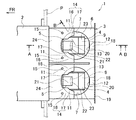
- FIG. 1 is a plan view of a cup holder according to an embodiment of the present disclosure as viewed from above.
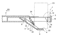
- FIG. 2 is a side cross-sectional view showing a state in which the cup holder is stored.
- FIG. 3 is a cross-sectional view taken along the line AA of FIG. 1 showing the state of the tray and flap when holding a large-diameter container.
- 4 is a cross-sectional view taken along the line BB of FIG. 1 showing a state in which a large-diameter container is held.
- FIG. 5 is a cross-sectional view taken along the line AA in FIG. 1 showing the state of the tray and flap when holding a small-diameter container.
- the storage direction of the holder main body will be described as the front, the pull-out direction as the rear, and the left and right in the state facing the front as the left and right directions, and the arrow FR in each figure indicates the front.
- the cup holder of this embodiment is arrange
- the cup holder 1 is configured to be compatible with two types of beverage containers C1 and C2 (see FIGS. 3 and 5) having different outer diameters, and is disposed and used in a vehicle interior.
- the large-diameter container (container) C1 is, for example, a thick can
- the small-diameter container (second container) C2 is, for example, a thin can.
- the cup holder 1 is schematically composed of a case 2, a holder body 3, left and right trays 4, and left and right flaps 5, which are formed of a hard resin material.
- the case 2 of the present embodiment is incorporated in the front inside of the instrument panel P of the vehicle and fixed to the instrument panel P, and the holder body 3 has a front storage position (see FIG. 2) and a rear use position (see FIG. 1 and FIG. 3) are supported by the case 2 so as to be slidable in the front-rear direction.
- the holder main body 3 in the storage position When holding the containers C1 and C2 using the cup holder 1, the holder main body 3 in the storage position is pulled out from the case 2 in the use state, and when stored after use, the holder main body 3 in the use position is pushed forward. In the storage state.
- the case 2 may be incorporated and fixed to other than the instrument panel P (for example, various consoles or seats provided in the passenger compartment).
- the holder body 3 has a flat upper tray portion 6 that is exposed to the outside of the case 2 and is held substantially horizontal in use.
- Two circular container insertion holes 7 that are slightly larger than the large-diameter container C1 are formed side by side in the upper tray portion 6, and the left and right trays 4 and the left and right flaps 5 are inserted into the left and right containers. Corresponding to the holes 7, they are attached to the holder body 3.
- the size and shape of the left and right container insertion holes 7 may be different, and one or three or more container insertion holes 7 may be formed.
- the upper tray portion 6 has two first opposing portions 11 and one second opposing portion 12 with respect to the left and right container insertion holes 7 (four first opposing portions 11 and two in total on the left and right sides).
- the first facing portion 11 and the second facing portion 12 constitute the peripheral edge of the container insertion hole 7.
- the 1st opposing part 11 is located in the right and left of the front side (one side) of the container penetration hole 7, and the 2nd opposing part 12 is located in the approximate center of the rear side (other side) of the container penetration hole 7,
- the facing portion 11 and the second facing portion 12 face each other with the container insertion hole 7 interposed therebetween.
- the peripheral part of the container insertion hole 7 including the 1st opposing part 11 is plate shape which is hard to bend and deform.
- the front end portion of the tray 4 is supported by the holder body 3 so as to be rotatable about the rotation shaft 8.
- the rotating shaft 8 extends to the left and right in front of the container insertion hole 7 and below the upper tray portion 6.
- a flat container mounting portion 9 is integrally formed at the rear end portion of the tray 4. The tilting range of the tray 4 around the rotation shaft 8 is set such that the container mounting portion 9 is in the storage position where the container mounting portion 9 is close to the container insertion hole 7 (see FIG. 2) and the unfolding position in which the container mounting portion 9 is lowered from the storage position ( 3 and FIG. 5).
- the upper surface of the container mounting portion 9 at the unfolded position is substantially horizontal below the container insertion hole 7 and supports the bottom surfaces of the containers C1 and C2 through which the container insertion hole 7 is inserted from below.
- Movement of the holder body 3 to the storage position is made possible by setting the tray 4 to the storage position.
- An urging member such as a leaf spring or a coil spring that urges the tray 4 to the storage position may be interposed between the holder body 3 and the tray 4.
- the front end portion of the flap 5 is supported by the holder body 3 so as to be rotatable about the rotation shaft 10, and the rotation shaft 10 extends to the left and right in front of the container insertion hole 7 and below the upper tray portion 6.
- the flap 5 can be tilted around the rotation shaft 10 from an initial position (see FIGS. 2 and 5) that is substantially the same height and substantially horizontal as the container insertion hole 7 to a lower retreat position (see FIG. 3).
- the upward tilt of the flap 5 is restricted by the initial position.
- the flap 5 is constantly biased to the initial position by a biasing member (not shown) such as a leaf spring or a coil spring interposed between the holder body 3 and the flap 5.
- the flap 5 is disposed substantially at the center of the front side of the container insertion hole 7 (between the two first opposing portions 11), and is integrated with a flat plate-like third opposing portion 13 that projects into the container insertion hole 7 at the initial position.
- the rear end surface of the third facing portion 13 is a curved surface that is recessed in an arc shape.
- the protrusion amount of the flap 5 (third facing portion 13) is set in accordance with the outer diameter of the small-diameter container C2.
- a resin flat plate 24 having a desired hardness is overlaid over a wide range and fixed by fastening with screws 15 and an adhesive.
- the flexible plate 24 has left and right first abutting portions 14, and the first abutting portion 14 includes a base end portion 16 fixed to the first facing portion 11 so as to overlap from above, and a base end portion 16. It has integrally the front-end
- the front end portion 17 is a flat plate shape that is thinner than the first opposing portion 11 of the upper tray portion 6 and easily deforms, and the end edge of the front end portion 17 is curved so as to be recessed in an arc shape.
- the number of the 1st contact parts 14 provided with respect to one container penetration hole 7 may be one, and may be three or more.
- one flexible plate (for example, left and right flexible plates with respect to the left and right first contact portions 14) may be provided for one first contact portion 14.
- a block-like pad (elastic member) 18 made of elastic resin is disposed and fixed below the second facing portion 12.
- the upper surface of the pad 18 is bonded to the lower surface of the upper tray portion 6, and in this state, the rear surface of the pad 18 approaches or contacts the front surface of the front plate portion 19 of the holder body 3.
- the front surface of the pad 18 is fixedly provided on the second facing portion 12 and constitutes a planar (planar or curved) second abutting portion 20 that stands up below the container insertion hole 7.
- a felt (biasing member) 21 made of a nonwoven fabric and having a desired elasticity is fixed to the third facing portion 13 of the flap 5 by adhesion or the like.
- a portion of the felt 21 that covers the rear end surface of the third facing portion 13 constitutes a third contact portion 22 that faces the second facing portion 12 at the initial position.
- a thick plate-like cushion (second elastic member) 23 made of elastic resin is fixed to the upper surface of the container mounting portion 9 of the tray 4 by adhesion or the like.
- the flap 5 (the third facing portion 13 and the third contact portion 22) is pushed by the container C1 and moved from the initial position to the retracted position, and the container The container C1 is allowed to descend to the placement state (see FIG. 3).
- the distal end portions 17 of the left and right first contact portions 14 of the flexible plate 24 bend downward and come into contact with the side surface of the container C1.
- C1 is pushed backward (see FIG. 4).
- the flap 5 (the third facing portion 13 and the third contact portion 22) is maintained at the initial position, and the second container placement state is reached. Allow the container C2 to descend (see FIG. 5). In the second container placement state in which the container C2 is supported by the container placement unit 9, the third contact portion 22 contacts the side surface of the container C2 and urges the container C2 rearward.
- the side surface (circumferential surface) of the large-diameter container C1 in the container placement state stands up with the distal end portion 17 of the flexible plate 24 (first contact portion 14) that is bent and deformed downward. It is sandwiched by the planar second contact portion 20 from the front and rear of the container insertion hole 7 (on the first facing portion 11 side and the second facing portion 12 side).
- the first facing portion 11 has a plate shape that is difficult to bend and deform, and the base end portion 16 of the first contact portion 14 is fixed to the first facing portion 11 so as to overlap from above, and the distal end of the first contact portion 14 is fixed.
- the portion 17 is a thin flat plate shape that is easier to bend and deform than the first facing portion 11 and extends integrally from the base end portion 16, the base end portion 16 of the base end portion 16 is bent and deformed downward. Lowering is reliably prevented by the first facing portion 11. For this reason, the downward displacement of the front-end
- the second contact portion 20 has a planar shape standing below the container insertion hole 7, the second contact portion 20 has the same height as or close to the tip portion 17 of the first contact portion 14. Comes into contact (surface contact) with the side surface of the container C1. That is, the side support positions on the front side and the rear side of the container insertion hole 7 can be set to substantially the same height. Therefore, the vibration of the container C1 in the container placement state can be sufficiently suppressed.
- the side surface of the large-diameter container C1 in the container placement state is sandwiched from three directions by the first contact portions 14 on the front left and right sides and the second contact portion 20 at the rear center, it is compared with the case of sandwiching from two directions. Thus, the holding state of the container C1 is stabilized.
- the pad 18 (second contact portion 20) is provided not in the entire circumference of the container insertion hole 7 but in a part (the rear side of the container insertion hole 7), the rear end portion (container of the tray 4 in the storage position) The mounting portion 9) and the pad 18 are unlikely to interfere with each other. Therefore, there is no need to greatly separate the container mounting portion 9 at the storage position downward from the container insertion hole 7 in order to avoid interference with the pad 18, which contributes to a compact storage state.
- the side surface of the small-diameter container C2 in the second container placement state is urged toward the second contact portion 20 by the third contact portion 22 and rises from the third contact portion 22. Since it is pinched
- the vibration suppressing effect of the containers C1 and C2 is improved.
- cup holder of the present disclosure can be applied to various vehicles.
- cup holder 2 case 3: holder body 4: tray 5: flap 6: upper tray part 7: container insertion hole 8, 10: rotating shaft 9: container mounting part 11: first opposing part 12: second opposing Part 13: Third facing part 14: First contact part 15: Screw 16: Base end part 17 of the first contact part 17: Tip part 18 of the first contact part 18: Pad (elastic member) 19: Front plate portion 20 of holder body: Second contact portion 21: Felt (urging member) 22: 3rd contact part 23: Cushion (2nd elastic member) 24: Flexible plate C1: Large diameter container (container) C2: Small diameter container (second container) P: Instrument panel
Landscapes
- Engineering & Computer Science (AREA)
- Physics & Mathematics (AREA)
- Thermal Sciences (AREA)
- Transportation (AREA)
- Mechanical Engineering (AREA)
- Passenger Equipment (AREA)
Abstract
容器挿通孔を挟んで対峙する第1対向部及び第2対向部がホルダ本体に設けられ、第1当接部の基端部が第1対向部に上方から重なって固定され、第1当接部の先端部が容器挿通孔へ突出し、第2対向部には容器挿通孔の下方で起立する面状の第2当接部が固定的に設けられる。第1対向部は、撓み変形し難い板状であり、第1当接部の先端部は、第1対向部よりも薄く撓み変形し易い平板状である。容器が容器挿通孔を挿通して容器載置部に支持された容器載置状態で、第1当接部の先端部は、下方へ撓んで容器の側面に当接し、容器を第2当接部側へ押圧する。
Description
本開示は、車両のカップホルダに関する。
特許文献1には、自動車等の車両に装備されるカップホルダが記載されている。このカップホルダにおいては、カップホルダを使用する場合に、カップホルダのトレイを格納ケースから車室内側へ引き出し、トレイに穿設された容器挿入孔内にカップを挿入する。容器挿入孔内には、ゴム板からなる保持部材の先端部が突出し、保持部材が弾性変形してカップの側面を押圧する。これにより、支持バーによって底部が支持されたカップの側面が保持部材の先端部に押圧され、容器挿入孔内でのカップのがたつきが抑制される。また、特許文献1には、トレイに保持部材が下方から重なって固定された状態が図示されている。
カップホルダ内での容器の振動の抑制効果は、容器の側面の横移動を規制する位置が低いほど低下する。つまり、容器の振動抑制効果は、容器に対する側方支持位置が低いほど低下する。また、容器の側面を横方向両側から挟んで保持する場合、一側の側方支持位置の高さと他側の側方支持位置の高さとが相違する、つまり、両側の側方支持位置が高さ方向にオフセットしていると、容器の振動抑制効果が低下する。
特許文献1のカップホルダでは、容器挿入孔が設けられたトレイ(ホルダ本体)にゴム板からなる保持部材が重なって固定されているため、保持部材の先端部が下方へ大きく変位し、容器に対する側方支持位置が低くなるとともに、両側の側方支持位置が高さ方向にオフセットしている。このため、容器の振動を十分に抑制できない可能性がある。
本開示の目的は、容器の振動抑制効果に優れたカップホルダを提供することである。
本開示の第1の態様は、ホルダ本体の容器挿通孔に容器を上方から挿入することにより、容器が容器挿通孔を挿通した状態で容器載置部によって下方から支持されるカップホルダであって、容器挿通孔の一側に位置する第1対向部と、容器挿通孔の他側に位置する第2対向部と、第1当接部と、第2当接部とを備える。第1対向部及び第2対向部は、ホルダ本体に設けられ、容器挿通孔を挟んで対峙する。
第1当接部は、第1対向部に上方から重なって固定される基端部と、容器挿通孔へ突出する先端部とを一体的に有する。第1対向部は、撓み変形し難い板状であり、第1当接部の先端部は、第1対向部よりも薄く撓み変形し易い平板状である。第2当接部は、第2対向部に固定的に設けられ、少なくとも容器挿通孔の下方で起立する面状である。容器が容器挿通孔を挿通して容器載置部に支持された容器載置状態で、第1当接部の先端部は、下方へ撓んで容器の側面に当接し、容器を容器挿通孔の前記他側へ押圧する。
上記構成では、容器載置状態の容器の側面(周面)は、下方に撓み変形した第1当接部の先端部と、起立する面状(平面状又は曲面状)の第2当接部とによって、容器挿通孔の前記一側及び前記他側(第1対向部側及び第2対向部側)から挟まれる。第1対向部は、撓み変形し難い板状であり、第1当接部の基端部は、第1対向部に上方から重なって固定され、第1当接部の先端部は、第1対向部よりも撓み変形し易い平板状(例えば第1対向部よりも薄い板状)であって基端部から一体的に延びているので、先端部が下方へ撓み変形する際の基端部の下降が第1対向部によって確実に防止される。このため、先端部の下方への変位を小さく抑えることができ、容器に対する側方支持位置の低下を抑制することができる。また、第2当接部を、少なくとも容器挿通孔の下方で起立する面状としたので、第1当接部の先端部と同じ高さ又は近い高さで第2当接部が容器の側面に当接(面接触)する。すなわち、容器挿通孔の前記一側及び前記他側の側方支持位置を略同じ高さとすることができる。従って、容器載置状態の容器の振動を十分に抑制することができる。
また、容器挿通孔の下方で起立する面状の第2当接部を、容器挿通孔の全周域ではなく一部(容器挿通孔の前記他側)に対して設ければよいので、ホルダ本体の大型化を抑制することができる。
本開示の第2の態様は、第1の態様のカップホルダであって、第2当接部は、第2対向部に対して固定された弾性部材の外面である。
上記構成では、容器の側面(周面)が第1対向部側及び第2対向部側の双方から弾性支持されるので、容器の振動抑制効果が向上する。
本開示の第3の態様は、第1又は第2の態様のカップホルダであって、第3対向部と、第3当接部とを備える。第3対向部は、容器挿通孔の前記一側に配置され、初期位置から下方の退避位置へ移動可能にホルダ本体に支持されて初期位置に付勢され、初期位置で容器挿通孔に突出する。第3当接部は、第3対向部とともに移動可能に第3対向部に固定的に設けられ、少なくとも初期位置で第2対向部と対向する。
容器を容器挿通孔に上方から挿入した場合、第3対向部及び第3当接部は、容器に押下され初期位置から退避位置へ移動して、容器載置状態への容器の降下を許容する。
容器よりも小径な第2の容器を容器挿通孔に上方から挿入した場合、第3対向部及び第3当接部は、初期位置に維持された状態で、容器挿通孔を挿通して容器載置部に支持される第2容器載置状態への第2の容器の降下を許容する。第3当接部は、第2容器載置状態の第2の容器の側面に当接し、第2の容器を容器挿通孔の前記他側へ付勢する付勢部材である。
上記構成では、容器(例えば太缶)を容器挿通孔に上方から挿入した場合、第3対向部及び第3当接部は、容器に押下され初期位置から退避位置へ移動して、容器載置状態への容器の降下を許容し、容器載置状態の容器の側面は、第1の態様と同様に、下方に撓み変形した第1当接部の先端部と、起立する面状の第2当接部とによって、容器挿通孔の一側及び他側から挟まれる。
また、容器よりも小径な第2の容器(例えば細缶)を容器挿通孔に上方から挿入した場合、第3対向部及び第3当接部は、初期位置に維持された状態で、容器挿通孔を挿通して容器載置部に支持される第2容器載置状態への第2の容器の降下を許容する。第3当接部は、第2容器載置状態の第2の容器の側面に当接し、第2の容器を第2当接部に向けて付勢する付勢部材であるので、第2容器載置状態の第2の容器の側面は、第3当接部と起立する面状の第2当接部とによって、容器挿通孔の前記一側及び前記他側から挟まれる。
従って、外径の相違する容器と第2の容器とをカップホルダによって選択的に支持することができる。また、第2の容器の場合、第2容器載置状態の第2の容器の側面は、第3当接部によって第2当接部に向けて付勢され、第3当接部と起立する面状の第2当接部とによって、容器挿通孔の前記一側及び前記他側から挟まれるので、第2の容器の振動を確実に抑制することができる。
本開示の第4の態様は、第1~第3の態様のカップホルダであって、容器載置部の上面に第2の弾性部材が固定されている。
上記構成では、容器載置状態の容器又は第2容器載置状態の第2の容器が下方から弾性支持されるので、容器又は第2の容器の振動抑制効果が向上する。
本開示のカップホルダによれば、容器の振動を確実に抑制することができる。
以下、本開示の一実施形態について図面を参照して詳細に説明する。なお、以下の説明において、ホルダ本体の格納方向を前方、引出方向を後方、前方を向いた状態での左右を左右方向として説明し、各図の矢印FRは前方を示す。なお、本実施形態のカップホルダは、格納方向が車両前方と略一致するように配置される。
本実施形態に係るカップホルダ1は、外径の異なる2種類の飲料容器C1,C2(図3及び図5参照)に対応可能に構成され、車両の室内に配置されて使用される。大径の容器(容器)C1は例えば太缶であり、小径の容器(第2の容器)C2は例えば細缶である。
図1~図3に示すように、カップホルダ1は、ケース2と、ホルダ本体3と、左右のトレイ4と、左右のフラップ5とから概略構成され、これらは硬質樹脂材によって形成されている。本実施形態のケース2は、車両のインストルメントパネルPの前方内部に組み込まれてインストルメントパネルPに固定され、ホルダ本体3は、前方の収納位置(図2参照)と後方の使用位置(図1及び図3参照)との間を前後方向にスライド移動自在にケース2に支持される。カップホルダ1を使用して容器C1,C2を保持する場合、収納位置のホルダ本体3をケース2から後方に引出して使用状態とし、使用後に収納する場合、使用位置のホルダ本体3を前方に押込んで収納状態とする。なお、ケース2、ホルダ本体3、トレイ4及びフラップ5を、樹脂以外の材料によって形成してもよい。また、ケース2をインストルメントパネルP以外(例えば、車室内に設けられる各種のコンソールや座席側等)に組み込んで固定してもよい。
ホルダ本体3は、使用状態でケース2外へ露出して略水平に保持される平板状の上トレイ部6を有する。上トレイ部6には、大径の容器C1よりも僅かに大きい円形状の2つの容器挿通孔7が左右に並んで形成され、左右のトレイ4と左右のフラップ5とは、左右の容器挿通孔7にそれぞれ対応してホルダ本体3に取付けられている。なお、左右の容器挿通孔7の大きさや形状を異ならせてもよく、1つ又は3つ以上の容器挿通孔7を形成してもよい。
上トレイ部6は、左右の容器挿通孔7に対してそれぞれ2箇所の第1対向部11と1箇所の第2対向部12と(左右合わせて4箇所の第1対向部11と2箇所の第2対向部12と)を有し、第1対向部11及び第2対向部12は、それぞれ容器挿通孔7の周縁部を構成する。第1対向部11は、容器挿通孔7の前側(一側)の左右に位置し、第2対向部12は、容器挿通孔7の後側(他側)の略中央に位置し、第1対向部11と第2対向部12とは、容器挿通孔7を挟んで対峙する。また、第1対向部11を含む容器挿通孔7の周縁部は、撓み変形し難い板状である。
トレイ4の前端部は、回転軸8を中心として回転可能にホルダ本体3に支持される。回転軸8は、容器挿通孔7の前方であって上トレイ部6の下方で左右に延び、トレイ4の後端部には、平板状の容器載置部9が一体形成されている。回転軸8を中心としたトレイ4の傾動範囲は、容器載置部9が容器挿通孔7に近接する格納位置(図2参照)と、容器載置部9が格納位置から下降した展開位置(図3及び図5参照)との間に規制される。展開位置の容器載置部9の上面は、容器挿通孔7の下方で略水平となり、容器挿通孔7を挿通する容器C1,C2の底面を下方から支持する。ホルダ本体3の収納位置への移動(使用状態から収納状態への移行)は、トレイ4を格納位置とすることによって可能となり、ホルダ本体3を収納位置から使用位置へ移動すると、トレイ4は、自重によって展開位置へ下降する。なお、トレイ4を格納位置へ付勢する板バネやコイルバネ等の付勢部材をホルダ本体3とトレイ4との間に介在させてもよい。
フラップ5の前端部は、回転軸10を中心として回転可能にホルダ本体3に支持され、回転軸10は、容器挿通孔7の前方であって上トレイ部6の下方で左右に延びる。フラップ5は、容器挿通孔7と略同高さで略水平となる初期位置(図2及び図5参照)から下方の退避位置(図3参照)へ回転軸10を中心として傾動可能であり、フラップ5の上方への傾動は、初期位置までに規制されている。フラップ5は、ホルダ本体3とフラップ5との間に介在する板バネやコイルバネ等の付勢部材(図示省略)によって、初期位置へ常時付勢されている。
フラップ5は、容器挿通孔7の前側の略中央(2箇所の第1対向部11の間)に配置され、初期位置で容器挿通孔7に突出する平板状の第3対向部13を一体的に有する。第3対向部13の後端面は、円弧状に凹む湾曲面である。フラップ5(第3対向部13)の突出量は、小径の容器C2の外径に合わせて設定される。
上トレイ部6の上面の前側領域には、所望の硬さを有する樹脂製平板状の可撓板24が広範囲に亘って上方から重ねられ、ビス15による締結及び接着剤によって固定されている。可撓板24は、左右の第1当接部14を有し、第1当接部14は、第1対向部11に上方から重なって固定される基端部16と、基端部16から延びて容器挿通孔7へ突出する先端部17とを一体的に有する。先端部17は、上トレイ部6の第1対向部11よりも薄く撓み変形し易い平板状であり、先端部17の端縁は、円弧状に凹むように湾曲している。なお、1つの容器挿通孔7に対して設ける第1当接部14の数は、1つであってもよく、3つ以上であってもよい。また、1つの第1当接部14に対して1枚の可撓板(例えば、左右の第1当接部14に対して左右の可撓板)を設けてもよい。
第2対向部12の下方には、弾性樹脂製のブロック状のパッド(弾性部材)18が配置され固定されている。パッド18の上面は上トレイ部6の下面に接着され、係る状態でパッド18の後面はホルダ本体3の前板部19の前面に近接又は接触する。パッド18の前面は、第2対向部12に固定的に設けられ、容器挿通孔7の下方で起立する面状(平面状又は曲面状)の第2当接部20を構成する。
フラップ5の第3対向部13には、不織布からなり所望の弾力を有するフェルト(付勢部材)21が接着等によって固定されている。フェルト21のうち第3対向部13の後端面を覆う部分は、初期位置で第2対向部12と対向する第3当接部22を構成する。また、トレイ4の容器載置部9の上面には、弾性樹脂製の厚板状のクッション(第2の弾性部材)23が接着等によって固定されている。
大径の容器C1を容器挿通孔7に上方から挿入すると、フラップ5(第3対向部13及び第3当接部22)は、容器C1に押下され初期位置から退避位置へ移動して、容器載置状態への容器C1の降下を許容する(図3参照)。容器C1が容器載置部9に支持された容器載置状態では、可撓板24の左右の第1当接部14の先端部17は、下方へ撓んで容器C1の側面に当接し、容器C1を後方へ押圧する(図4参照)。
小径の容器C2を容器挿通孔7に上方から挿入すると、フラップ5(第3対向部13及び第3当接部22)は、初期位置に維持された状態で、第2容器載置状態への容器C2の降下を許容する(図5参照)。容器C2が容器載置部9に支持された第2容器載置状態では、第3当接部22は、容器C2の側面に当接し、容器C2を後方へ付勢する。
本実施形態によれば、容器載置状態の大径の容器C1の側面(周面)は、下方に撓み変形した可撓板24(第1当接部14)の先端部17と、起立する面状の第2当接部20とによって、容器挿通孔7の前後(第1対向部11側及び第2対向部12側)から挟まれる。第1対向部11は、撓み変形し難い板状であり、第1当接部14の基端部16は、第1対向部11に上方から重なって固定され、第1当接部14の先端部17は、第1対向部11よりも撓み変形し易い薄い平板状であって基端部16から一体的に延びているので、先端部17が下方へ撓み変形する際の基端部16の下降が第1対向部11によって確実に防止される。このため、先端部17の下方への変位を小さく抑えることができ、容器C1に対する側方支持位置の低下を抑制することができる。また、第2当接部20を、容器挿通孔7の下方で起立する面状としたので、第1当接部14の先端部17と同じ高さ又は近い高さで第2当接部20が容器C1の側面に当接(面接触)する。すなわち、容器挿通孔7の前側及び後側の側方支持位置を略同じ高さとすることができる。従って、容器載置状態の容器C1の振動を十分に抑制することができる。
容器載置状態の大径の容器C1の側面は、前側左右の第1当接部14と、後側中央の第2当接部20とによって3方向から挟むので、2方向から挟む場合に比べて容器C1の保持状態が安定する。
パッド18(第2当接部20)を、容器挿通孔7の全周域ではなく一部(容器挿通孔7の後側)に設けているので、格納位置のトレイ4の後端部(容器載置部9)とパッド18とが干渉し難い。従って、パッド18との干渉を避けるために格納位置の容器載置部9を容器挿通孔7から下方に大きく離間させる必要性がなく、格納状態のコンパクト化に寄与する。
第2容器載置状態の小径の容器C2の側面は、第3当接部22によって第2当接部20に向けて付勢され、第3当接部22と起立する面状の第2当接部20とによって、容器挿通孔7の前後から挟まれるので、容器C2の振動を確実に抑制することができる。
さらに、容器載置状態の容器C1又は第2容器載置状態の容器C2がクッション23によって下方から弾性支持されるので、容器C1,C2の振動抑制効果が向上する。
以上、本開示について、上記実施形態に基づいて説明を行ったが、本発明は上記実施形態の内容に限定されるものではなく、当然に本開示を逸脱しない範囲で適宜変更が可能である。すなわち、この実施形態に基づいて当業者等によりなされる他の実施形態、実施例および運用技術等は全て本発明の範疇に含まれることは勿論である。
例えば、上記実施形態では収納タイプのカップホルダについて説明したが、非収納タイプのカップホルダであってもよい。
本出願は、2018年6月7日付で出願された日本国特許出願(特願2018-109360)に基づくものであり、その内容はここに参照として取り込まれる。
本開示のカップホルダは、様々な車両に適用可能である。
1:カップホルダ
2:ケース
3:ホルダ本体
4:トレイ
5:フラップ
6:上トレイ部
7:容器挿通孔
8,10:回転軸
9:容器載置部
11:第1対向部
12:第2対向部
13:第3対向部
14:第1当接部
15:ビス
16:第1当接部の基端部
17:第1当接部の先端部
18:パッド(弾性部材)
19:ホルダ本体の前板部
20:第2当接部
21:フェルト(付勢部材)
22:第3当接部
23:クッション(第2の弾性部材)
24:可撓板
C1:大径の容器(容器)
C2:小径の容器(第2の容器)
P:インストルメントパネル
2:ケース
3:ホルダ本体
4:トレイ
5:フラップ
6:上トレイ部
7:容器挿通孔
8,10:回転軸
9:容器載置部
11:第1対向部
12:第2対向部
13:第3対向部
14:第1当接部
15:ビス
16:第1当接部の基端部
17:第1当接部の先端部
18:パッド(弾性部材)
19:ホルダ本体の前板部
20:第2当接部
21:フェルト(付勢部材)
22:第3当接部
23:クッション(第2の弾性部材)
24:可撓板
C1:大径の容器(容器)
C2:小径の容器(第2の容器)
P:インストルメントパネル
Claims (4)
- ホルダ本体の容器挿通孔に容器を上方から挿入することにより、前記容器が前記容器挿通孔を挿通した状態で容器載置部によって下方から支持されるカップホルダであって、
前記ホルダ本体に設けられ前記容器挿通孔を挟んで対峙する、前記容器挿通孔の一側に位置する第1対向部及び前記容器挿通孔の他側に位置する第2対向部と、
前記第1対向部に上方から重なって固定される基端部と、前記容器挿通孔へ突出する先端部とを一体的に有する第1当接部と、
前記第2対向部に固定的に設けられ、少なくとも前記容器挿通孔の下方で起立する面状の第2当接部と、を備え、
前記第1対向部は、撓み変形し難い板状であり、
前記第1当接部の前記先端部は、前記第1対向部よりも薄く撓み変形し易い平板状であり、
前記容器が前記容器挿通孔を挿通して前記容器載置部に支持された容器載置状態で、前記第1当接部の前記先端部は、下方へ撓んで前記容器の側面に当接し、前記容器を前記容器挿通孔の前記他側へ押圧する
ことを特徴とするカップホルダ。 - 請求項1に記載のカップホルダであって、
前記第2当接部は、前記第2対向部に対して固定された弾性部材の外面である
ことを特徴とするカップホルダ。 - 請求項1又は請求項2に記載のカップホルダであって、
前記容器挿通孔の前記一側に配置され、初期位置から下方の退避位置へ移動可能に前記ホルダ本体に支持されて前記初期位置に付勢され、前記初期位置で前記容器挿通孔に突出する第3対向部と、
前記第3対向部とともに移動可能に前記第3対向部に固定的に設けられ、少なくとも前記初期位置で前記第2対向部と対向する第3当接部と、を備え、
前記容器を前記容器挿通孔に上方から挿入した場合、前記第3対向部及び前記第3当接部は、前記容器に押下され前記初期位置から前記退避位置へ移動して、前記容器載置状態への前記容器の降下を許容し、
前記容器よりも小径な第2の容器を前記容器挿通孔に上方から挿入した場合、前記第3対向部及び前記第3当接部は、前記初期位置に維持された状態で、前記容器挿通孔を挿通して前記容器載置部に支持される第2容器載置状態への前記第2の容器の降下を許容し、
前記第3当接部は、前記第2容器載置状態の前記第2の容器の側面に当接し、前記第2の容器を前記容器挿通孔の前記他側へ付勢する付勢部材である
ことを特徴とするカップホルダ。 - 請求項1~請求項3の何れか1項に記載のカップホルダであって、
前記容器載置部の上面に第2の弾性部材が固定されている
ことを特徴とするカップホルダ。
Priority Applications (1)
| Application Number | Priority Date | Filing Date | Title |
|---|---|---|---|
| CN201980038541.4A CN112262060A (zh) | 2018-06-07 | 2019-06-04 | 杯架 |
Applications Claiming Priority (2)
| Application Number | Priority Date | Filing Date | Title |
|---|---|---|---|
| JP2018-109360 | 2018-06-07 | ||
| JP2018109360A JP2019209900A (ja) | 2018-06-07 | 2018-06-07 | カップホルダ |
Publications (1)
| Publication Number | Publication Date |
|---|---|
| WO2019235488A1 true WO2019235488A1 (ja) | 2019-12-12 |
Family
ID=68770877
Family Applications (1)
| Application Number | Title | Priority Date | Filing Date |
|---|---|---|---|
| PCT/JP2019/022216 Ceased WO2019235488A1 (ja) | 2018-06-07 | 2019-06-04 | カップホルダ |
Country Status (3)
| Country | Link |
|---|---|
| JP (1) | JP2019209900A (ja) |
| CN (1) | CN112262060A (ja) |
| WO (1) | WO2019235488A1 (ja) |
Citations (7)
| Publication number | Priority date | Publication date | Assignee | Title |
|---|---|---|---|---|
| JPH0540030U (ja) * | 1991-11-06 | 1993-05-28 | 豊田合成株式会社 | 車輌用冷温装置 |
| JPH0665085U (ja) * | 1993-02-24 | 1994-09-13 | 加藤発条株式会社 | カップホルダー |
| JPH0737787U (ja) * | 1993-12-24 | 1995-07-11 | 日野自動車工業株式会社 | 車両の容器ホルダ |
| JPH0911790A (ja) * | 1995-06-30 | 1997-01-14 | Isuzu Motors Ltd | 車両用カップスタンド |
| JPH0958323A (ja) * | 1995-08-28 | 1997-03-04 | Kojima Press Co Ltd | カップホルダ装置 |
| JPH09169235A (ja) * | 1996-12-24 | 1997-06-30 | Nifco Inc | 車両用カップホルダー |
| JPH10324188A (ja) * | 1997-05-26 | 1998-12-08 | Hino Motors Ltd | 容器ホルダ |
Family Cites Families (6)
| Publication number | Priority date | Publication date | Assignee | Title |
|---|---|---|---|---|
| JPH08295169A (ja) * | 1995-04-27 | 1996-11-12 | Toyoda Gosei Co Ltd | カップホルダ及びその製造方法 |
| JP4878666B2 (ja) * | 1999-10-21 | 2012-02-15 | 株式会社ニフコ | カップホルダー |
| JP4807911B2 (ja) * | 2001-09-06 | 2011-11-02 | 株式会社ニフコ | カップホルダ |
| JP4029336B2 (ja) * | 2003-01-20 | 2008-01-09 | 豊田合成株式会社 | 収納式カップホルダ |
| JP5013166B2 (ja) * | 2006-09-05 | 2012-08-29 | 豊田合成株式会社 | 容器ホルダ装置 |
| JP2009143507A (ja) * | 2007-12-18 | 2009-07-02 | Nissan Motor Co Ltd | 車両用収納装置 |
-
2018
- 2018-06-07 JP JP2018109360A patent/JP2019209900A/ja active Pending
-
2019
- 2019-06-04 WO PCT/JP2019/022216 patent/WO2019235488A1/ja not_active Ceased
- 2019-06-04 CN CN201980038541.4A patent/CN112262060A/zh active Pending
Patent Citations (7)
| Publication number | Priority date | Publication date | Assignee | Title |
|---|---|---|---|---|
| JPH0540030U (ja) * | 1991-11-06 | 1993-05-28 | 豊田合成株式会社 | 車輌用冷温装置 |
| JPH0665085U (ja) * | 1993-02-24 | 1994-09-13 | 加藤発条株式会社 | カップホルダー |
| JPH0737787U (ja) * | 1993-12-24 | 1995-07-11 | 日野自動車工業株式会社 | 車両の容器ホルダ |
| JPH0911790A (ja) * | 1995-06-30 | 1997-01-14 | Isuzu Motors Ltd | 車両用カップスタンド |
| JPH0958323A (ja) * | 1995-08-28 | 1997-03-04 | Kojima Press Co Ltd | カップホルダ装置 |
| JPH09169235A (ja) * | 1996-12-24 | 1997-06-30 | Nifco Inc | 車両用カップホルダー |
| JPH10324188A (ja) * | 1997-05-26 | 1998-12-08 | Hino Motors Ltd | 容器ホルダ |
Also Published As
| Publication number | Publication date |
|---|---|
| JP2019209900A (ja) | 2019-12-12 |
| CN112262060A (zh) | 2021-01-22 |
Similar Documents
| Publication | Publication Date | Title |
|---|---|---|
| US8360380B2 (en) | Cup holder with flexible protruding portion | |
| JP5661696B2 (ja) | 乗り物用シート装置 | |
| CN108025680B (zh) | 车辆内部部件 | |
| JP2010516540A (ja) | テーブル形成部材を有する折り重ね式背部を備える自動車の座席、及びそのような座席を有する自動車 | |
| JP2014034245A5 (ja) | ||
| US20050104422A1 (en) | Structure for securing cup support element in automotive seat | |
| US7568749B2 (en) | Retractable cup holder assembly | |
| WO2014024584A1 (ja) | 乗り物用シート装置 | |
| JP5535781B2 (ja) | カップホルダ | |
| JP2019209900A (ja) | カップホルダ | |
| JP2014053189A (ja) | スイッチ装置 | |
| KR101447930B1 (ko) | 자동차용 포착암 절곡형 컵홀더 | |
| CN107968011A (zh) | 输入装置 | |
| JP5533379B2 (ja) | 車両用アクセサリ取付具 | |
| US20110095060A1 (en) | Device for laterally positioning an object in a container | |
| WO2023038021A1 (ja) | 車両のカップホルダ構造 | |
| JP2013095244A (ja) | 回動体装置及び収納装置 | |
| US10195974B2 (en) | Detent for vehicle armrest | |
| US12370958B2 (en) | Device storage holder for vehicle | |
| JP6873172B2 (ja) | 飲料容器保持装置 | |
| US20240326700A1 (en) | Storage device for securely storing objects in a motor vehicle | |
| JP2026084437A (ja) | 収納装置 | |
| JP5806655B2 (ja) | 車両用携帯端末保持装置 | |
| JP2018165121A (ja) | 着座センサ | |
| JP4961173B2 (ja) | 格納式カップホルダー |
Legal Events
| Date | Code | Title | Description |
|---|---|---|---|
| 121 | Ep: the epo has been informed by wipo that ep was designated in this application |
Ref document number: 19815362 Country of ref document: EP Kind code of ref document: A1 |
|
| NENP | Non-entry into the national phase |
Ref country code: DE |
|
| 122 | Ep: pct application non-entry in european phase |
Ref document number: 19815362 Country of ref document: EP Kind code of ref document: A1 |